EP3410173B1 - Optisches verstärkermodul mit kurzer reichweite, verstärkungsverfahren und verstärkungssystem - Google Patents
Optisches verstärkermodul mit kurzer reichweite, verstärkungsverfahren und verstärkungssystem Download PDFInfo
- Publication number
- EP3410173B1 EP3410173B1 EP16887070.7A EP16887070A EP3410173B1 EP 3410173 B1 EP3410173 B1 EP 3410173B1 EP 16887070 A EP16887070 A EP 16887070A EP 3410173 B1 EP3410173 B1 EP 3410173B1
- Authority
- EP
- European Patent Office
- Prior art keywords
- optical
- polarization direction
- phase delay
- plate
- imaging lens
- Prior art date
- Legal status (The legal status is an assumption and is not a legal conclusion. Google has not performed a legal analysis and makes no representation as to the accuracy of the status listed.)
- Active
Links
Images


Classifications
-
- G—PHYSICS
- G02—OPTICS
- G02B—OPTICAL ELEMENTS, SYSTEMS OR APPARATUS
- G02B27/00—Optical systems or apparatus not provided for by any of the groups G02B1/00 - G02B26/00, G02B30/00
- G02B27/01—Head-up displays
- G02B27/0101—Head-up displays characterised by optical features
-
- G—PHYSICS
- G02—OPTICS
- G02B—OPTICAL ELEMENTS, SYSTEMS OR APPARATUS
- G02B27/00—Optical systems or apparatus not provided for by any of the groups G02B1/00 - G02B26/00, G02B30/00
- G02B27/01—Head-up displays
- G02B27/017—Head mounted
- G02B27/0172—Head mounted characterised by optical features
-
- G—PHYSICS
- G02—OPTICS
- G02B—OPTICAL ELEMENTS, SYSTEMS OR APPARATUS
- G02B17/00—Systems with reflecting surfaces, with or without refracting elements
- G02B17/08—Catadioptric systems
- G02B17/0856—Catadioptric systems comprising a refractive element with a reflective surface, the reflection taking place inside the element, e.g. Mangin mirrors
- G02B17/086—Catadioptric systems comprising a refractive element with a reflective surface, the reflection taking place inside the element, e.g. Mangin mirrors wherein the system is made of a single block of optical material, e.g. solid catadioptric systems
-
- G—PHYSICS
- G02—OPTICS
- G02B—OPTICAL ELEMENTS, SYSTEMS OR APPARATUS
- G02B27/00—Optical systems or apparatus not provided for by any of the groups G02B1/00 - G02B26/00, G02B30/00
- G02B27/0025—Optical systems or apparatus not provided for by any of the groups G02B1/00 - G02B26/00, G02B30/00 for optical correction, e.g. distorsion, aberration
-
- G—PHYSICS
- G02—OPTICS
- G02B—OPTICAL ELEMENTS, SYSTEMS OR APPARATUS
- G02B27/00—Optical systems or apparatus not provided for by any of the groups G02B1/00 - G02B26/00, G02B30/00
- G02B27/28—Optical systems or apparatus not provided for by any of the groups G02B1/00 - G02B26/00, G02B30/00 for polarising
-
- G—PHYSICS
- G02—OPTICS
- G02B—OPTICAL ELEMENTS, SYSTEMS OR APPARATUS
- G02B27/00—Optical systems or apparatus not provided for by any of the groups G02B1/00 - G02B26/00, G02B30/00
- G02B27/28—Optical systems or apparatus not provided for by any of the groups G02B1/00 - G02B26/00, G02B30/00 for polarising
- G02B27/286—Optical systems or apparatus not provided for by any of the groups G02B1/00 - G02B26/00, G02B30/00 for polarising for controlling or changing the state of polarisation, e.g. transforming one polarisation state into another
-
- G—PHYSICS
- G02—OPTICS
- G02B—OPTICAL ELEMENTS, SYSTEMS OR APPARATUS
- G02B5/00—Optical elements other than lenses
- G02B5/003—Light absorbing elements
-
- G—PHYSICS
- G02—OPTICS
- G02B—OPTICAL ELEMENTS, SYSTEMS OR APPARATUS
- G02B5/00—Optical elements other than lenses
- G02B5/30—Polarising elements
-
- G—PHYSICS
- G02—OPTICS
- G02B—OPTICAL ELEMENTS, SYSTEMS OR APPARATUS
- G02B5/00—Optical elements other than lenses
- G02B5/30—Polarising elements
- G02B5/3025—Polarisers, i.e. arrangements capable of producing a definite output polarisation state from an unpolarised input state
-
- G—PHYSICS
- G02—OPTICS
- G02B—OPTICAL ELEMENTS, SYSTEMS OR APPARATUS
- G02B27/00—Optical systems or apparatus not provided for by any of the groups G02B1/00 - G02B26/00, G02B30/00
- G02B27/01—Head-up displays
- G02B27/0101—Head-up displays characterised by optical features
- G02B2027/013—Head-up displays characterised by optical features comprising a combiner of particular shape, e.g. curvature
-
- G—PHYSICS
- G02—OPTICS
- G02B—OPTICAL ELEMENTS, SYSTEMS OR APPARATUS
- G02B5/00—Optical elements other than lenses
- G02B5/30—Polarising elements
- G02B5/3083—Birefringent or phase retarding elements
Definitions
- the present invention relates to optical apparatuses, and in particular, to a short-distance optical amplification module, an amplification method and an amplification system.
- the module in order to meet the imaging quality requirement of the optical amplification module, the module generally includes a plurality of optical devices. Because each optical device requires a certain mounting space, the optical amplification module consisted of the plurality of optical devices often has a large size and a large volume, which in particular cannot meet the display requirements on small space and high amplification of an intelligent virtual reality (VR) wearable device.
- VR virtual reality
- US 20020159150 A1 discloses a collimating optical device utilizes a reflective beam splitter in the form of a linear polarizing beam splitter to achieve a wide field of view.
- One form of the wide-angle collimating optical device includes, in order from an image source, a first absorptive linear polarizer; a first quarter-wave plate; an optical doublet including a plano-concave singlet, a plano-convex singlet whose convex surface has the same curvature as the curvature of the concave surface, and a first reflective beam splitter joining the concave surface of the plano-concave singlet to the convex surface of the plano-convex singlet; a second quarter-wave plate; and a second reflective beam splitter.
- One of the reflective beam splitters is a linear polarizing beam splitter, most preferably a wire grid polarizer.
- US 2012/0147465 A1 discloses a collimating image-forming apparatus comprising a first linear polarizer is disclosed.
- a first quarter wave plate is disposed adjacent the first polarizer and has its fast and slow axes at substantially 45° to the plane of polarization of the first polarizer.
- the apparatus further comprises a beam-splitting curved mirror having a convex surface adjacent the first polarizer and facing towards the first quarter-wave plate, a second quarter-wave plate adjacent the concave side of the curved mirror, the second quarter wave plate having its having its fast and slow axes oriented with respect to the corresponding axes of the first quarter-wave plate at angles substantially equal to a first integral multiple of 90°, and a reflective-transmissive polarizing member adjacent the second quarter-wave plate.
- a second linear polarizer is adjacent the reflective-transmissive polarizing member, the second linear polarize: having its plane of polarization oriented with respect to the plane of polarization of the first linear polarizer at an angle substantially equal to a second integral multiple of 90°, both of the multiples being even or both being odd.
- EP 1 024 388 A2 discloses a compact, lightweight, multi-wavelength display system which can be used as a collimating eyepiece is provided.
- the system utilizes a polarization selective optical element, or PS element, that reflects one linear polarization state while transmitting radiation of the orthogonal linear polarization state.
- the PS element is used in combination with a quarter wave plate and an optical element, the optical element including a partially reflective surface.
- the optical element may either be a single element or an optical doublet. In the latter configuration, the partially reflective surface is at the interface between the two singlets that comprise the doublet.
- the system also includes an image source that either alone, or in combination with other optical elements, produces circularly polarized light of the desired rotary sense.
- Embodiments of the present invention provide a short-distance optical amplification module and an amplification method as set forth in the main claim 1 and 6, thereby solving the problem of large structural size of the existing optical amplification module.
- an optical image can be amplified on the imaging lens after being reflected by the reflective type polarizing plate on the transmission path.
- the optical image can meet the requirement of optical magnification, but also the second phase delay plate and the reflective type polarizing plate can be arranged to adhere to each other, thereby further reducing the size and volume of an optical module.
- the second phase delay plate and the imaging lens are arranged to adhere to each other.
- the distance between the second phase delay plate and the reflective polarizing plate can be reduced without affecting the optical path, and the size and volume of the short-distance optical amplification module can be further reduced.
- one side of the imaging lens is the second optical surface, so that the second optical surface can be adhered to the second phase delay plate, and the second phase delay plate is in turn adhered to the reflective polarizing plate, thus the size and volume of the short-distance optical amplification module can be further reduced.
- one side of the imaging lens is arranged as the second optical surface, so that the degree of chromatic dispersion of a polarized light when the imaging lens is the first optical surface is diminished, thereby improving the definition of the optical image. In comparison with the first optical surface, the mirror finishing process and process difficulty of the second optical surface will be lower, and the manufacturing cost will be small.
- an absorptive type polarizing plate is further added on the outer side of the reflective polarizing plate.
- the absorptive type polarizing plate can absorb the light from the outside and prevent a reflection image of the outside from being seen, thereby preventing the ambient light from interfering the optical image.
- the absorptive type polarizing plate, the reflection polarizing plate and the second phase delay plate are arranged to adhere to each other, and the optical display screen and the first phase delay plate are arranged to adhere to each other, thus the volume and size of the optical amplification module may be further reduced, and assembly may be simplified.
- an optical image is transmissively amplified via the imaging lens and then reflected on the reflective type polarizing plate.
- the reflected optical image passes through the imaging lens again, it is amplified on the first optical surface for the second time, and the polarization direction is converted from an elliptical or circular polarization direction into a non-second linear polarization direction.
- the polarization direction is converted from an elliptical or circular polarization direction into a non-second linear polarization direction.
- the reflective type polarizing plate By twice reflection of the optical image in the optical amplification module, not only the visual angle can be enlarged, but also the size and volume of the optical amplification module can be reduced.
- the short-distance optical amplification module is a multilayer optical structure consisted of a first phase delay layer, an imaging lens layer, a second phase delay layer and a reflective type polarization layer.
- the size and volume of the optical amplification module are greatly reduced without affecting the optical imaging quality, the weight is reduced, and the comfortableness of wearing VR glasses employing the optical amplification component is improved.
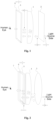
- a short-distance optical amplification module includes a first phase delay plate 2, an imaging lens 4, a second phase delay plate 5 and a reflective type polarizing plate 6 that are successively arranged, wherein, the first phase delay plate 2 is arranged in a transmission path of an optical image having a first linear polarization direction and is configured for converting the polarization direction of the optical image from the first linear polarization direction to an elliptical or circular polarization direction.
- the optical image refers to the light or polarized light emitted from the light source side.
- the imaging lens 2 is arranged in a transmission path of an optical image having an elliptical or circular polarization direction.
- the imaging lens 2 has a first optical surface adjacent to the first phase delay plate and a second optical surface opposite to the first optical surface, the first optical surface being a transflective optical surface, and the imaging lens is configured for amplifying an optical image passing through the first optical surface, said amplification is referred to as first-time amplification.
- the first optical surface is a curved surface
- the second optical surface is a flat surface
- the center of curvature of the first optical surface and the second optical surface are located on the same side of the first optical surface.
- the second phase delay plate 5 is arranged on one side of the second optical surface of the imaging lens 4 and is configured for converting the polarization direction of the optical image from the elliptical or circular polarization direction to a second linear polarization direction. Moreover, the second linear polarization direction is orthogonal to the first linear polarization direction.
- the reflective type polarizing plate 6 is adhered to the second phase delay plate 5, and the reflective type polarizing plate 6 has a transmission direction consistent with the first linear polarization direction.
- the optical image successively passes through the first phase delay plate 2, the imaging lens 4, the second phase delay plate 5 and the reflective type polarizing plate 6.
- the reflective type polarizing plate 6 is further configured for reflecting an optical image having a second linear polarization direction that is transmitted from the second phase delay plate 5, and the imaging lens 4 is configured for amplifying the optical image reflected by the reflective type polarizing plate 6, wherein said amplification is referred to as second-time amplification.
- the second phase delay plate 5 is further configured for converting the polarization direction of the second-time amplified optical image into a non-second linear polarization direction, thereby passing an optical image having the non-second linear polarization direction through the reflective type polarizing plate 6.
- non-second linear polarization direction is preferably the first linear polarization direction.
- the first phase delay plate 2, the second phase delay plate 5 and reflective polarizing plate 6 in this example all belong to the prior art. Each time an optical image passes through a phase delay plate, a certain degree of phase delay can be added.
- a reflective polarizing plate can transmit a linearly-polarized light with a polarization direction consistent with the transmission direction thereof, but totally reflect a linearly-polarized light with a polarization direction orthogonal to the transmission direction thereof, and partially transmit a circularly-polarized light or an elliptically-polarized light with a certain phase delay.
- the side adjacent to the first phase delay plate 2 is the first optical surface
- the side adjacent to the second phase delay plate 5 is the second optical surface
- the first optical surface is a transflective optical surface, by which a certain ratio of light may be reflected, and the remaining ratio of light may be transmitted.
- the polarization direction of the optical image is changed to a phase-delayed elliptical polarization direction or circular polarization direction.
- the first phase delay plate 2 is a 1/4 wave plate
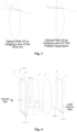
- the polarization direction of the optical image transmitted will be changed to a circular polarization direction after passing through the first phase delay plate 2, and then it will be transmitted when passing through the first optical surface of the imaging lens, so that the optical mage will be transmissively amplified.
- This amplification is a small amplification.
- the polarization direction of the optical image transmitted will be converted from the elliptical or circular polarization direction to a second linear polarization direction (in this example, vertical to the paper direction) after passing through the second phase delay plate 5.
- the second linear polarization direction is orthogonal to the first linear polarization direction.
- the direction of a polarized light rotated by the first phase delay plate 2 is consistent with that rotated by the second phase delay plate 5 (that is, the first phase delay plate 2 and the second phase delay plate 5 are both left-handed or right-handed phase delay plates).
- the optical image having a second linear polarization direction After reaching the reflective type polarizing plate 6, the optical image having a second linear polarization direction will be totally reflected. After the reflected optical image passes through the second phase delay plate 5 again, the polarization direction will be converted from the first linear polarization direction to an elliptical or circular polarization direction. Especially, when the second phase delay plate 5 is a 1/4 wave plate, after passing through the second phase delay plate 5, the polarization direction of the reflected optical image will be changed to a circular polarization direction.
- Light will be reflected and amplified with a certain ratio of energy when the optical image again passes through the first optical surface of the imaging lens 4 and is reflected, and this amplification is a large amplification.
- the optical image largely amplified passes through the second phase delay plate 5 again, and the polarization direction thereof is changed to a non-second linear polarization direction (preferably, the first linear polarization direction).
- the first phase delay plate 2 is a 1/4 wave plate, the polarization direction of the optical image is changed to the first linear polarization direction after passing through the first phase delay plate 2 again.
- the reflective type polarizing plate 6 has a transmission direction consistent with the first linear polarization direction, the optical image having a first linear polarization direction will enter the sight of a viewer via the reflective polarizing plate 6, so that large amplification of light may be realized in a short distance (less than 5cm).
- an optical image can be amplified on the imaging lens after being reflected by the reflective type polarizing plate on the transmission path.
- the optical image can meet the requirement of optical magnification, but also the second phase delay plate and the reflective type polarizing plate can be arranged to adhere to each other, thereby further reducing the size and volume of an optical module.
- the non-second linear polarization direction is the first linear polarization direction, so that the polarization direction of the optical image is changed to the first linear polarization direction again after passing through the second phase delay plate so as to guarantee that the optical image is totally reflected when reaching the reflective type polarizing plate for the first time. That is, at this moment, the polarization direction of the optical image is changed to a second linear polarization direction that is orthogonal to the first linear polarization direction, and the optical path difference of the optical image after passing through the first phase delay plate 2 and the second phase delay plate 4 is 1 2 , 1 1 2 , 2 1 2 ⁇ ⁇ n 1 2 , wherein n is an integer.
- the second phase delay plate 5 and the reflective polarizing plate 6 can be arranged to adhere to each other, thus the transmission path of the polarized light in the second phase delay plate 5 and the reflective polarizing plate 6 can be reduced.
- the distance between the second phase delay plate and the reflective polarizing plate can be reduced without affecting the optical path, and hence the size and volume of the short-distance optical amplification module can be further reduced.
- the second phase delay plate is adhered to the second optical surface of the imaging lens.
- the side of the imaging lens 4 (transflective curved lens 4) that is adjacent to the second phase delay plate 5 is provided as the second optical surface, and the flat surface can be adhered to the second phase delay plate 5.
- the mirror surface of the imaging lens 4 is a circular arc camber.
- the side of the imaging lens 4 adjacent to the second phase delay plate 5 is provided as a flat surface.
- the second phase delay plate 5 and the imaging lens 4 are adhered to each other, the distance between the two optical components is further shortened, and the size of the optical amplification module is reduced.
- the two sides of the imaging lens 4 are both curved surfaces, a too large curved surface will cause chromatic dispersion to the light, and hence the visual imaging effect will be affected; or, if the curvature of the curved surface is small, the optical path will be reduced, and the amplification effect will be affected.
- the degree of chromatic dispersion on the curved surface can be reduced, or the problem of small amplification on the optical path caused by a small curvature may be alleviated, thus the refraction or reflection of light in the optical module can be made more stable, and the imaging effect of the optical path will not be affected.
- one side of the transflective curved lens according to this example is a flat surface, and in comparison with the existing imaging lens of which the two sides are both curved surfaces, the manufacture difficulty of a flat surface is lower than that of a curved surface, and correspondingly, the manufacturing cost is also reduced, and hence the production efficiency can be improved.
- the short-distance optical amplification module further includes an absorptive type polarizing plate 7, wherein, the absorptive type polarizing plate 7 is arranged on one side of the reflective polarizing plate 6 that faces away from the imaging lens 4. Additionally, the absorptive type polarizing plate 7 may be adhered to the reflective polarizing plate 6, and the transmission direction of the absorptive type polarizing plate 7 is consistent with (parallel to) that of the absorptive type polarizing plate 7.
- an absorptive type polarizing plate may be added on the outer side of the reflective polarizing plate, and the transmission direction of the absorptive type polarizing plate is arranged parallel to that of the reflection polarizing plate. That is, a polarized light emitted from the reflection polarizing plate may directly pass through the absorptive type polarizing plate. The ambient light is absorbed by the absorptive type polarizing plate. Therefore, a reflection image of the outside may be prevented from being seen, and the interference to display by the outside light is prevented. Additionally, by adhering the reflection polarizing plate and the second phase delay plate to each other, light loss may be lowered, the volume and size may be further reduced, and assembly may be simplified.
- the short-distance optical amplification module further includes an optical display screen 1.
- the optical display screen 1 is arranged on one side of the first phase delay plate 2 that faces away from the transflective curved lens 4 and is configured for generating an optical image having a first linear polarization direction. Moreover, the optical display screen is adhered to the first phase delay plate 2.
- the short-distance optical amplification module in this example which does not fall under the scope of the claims, because the optical display screen 1 is adhered to the first phase delay plate 2 and the second phase delay plate 5 is adhered to the reflective polarizing plate 6, two sets of distances are reduced respectively.
- the size of the optical module can be greatly reduced.
- the short-distance optical amplification module is applied to VR glasses, the size and thickness of the VR glasses can be reduced, and the volume can be decreased, thus it may approach the size of ordinary glasses, and the comfortableness of a user wearing the VR glasses may be improved.
- the first optical surface of the above imaging lens 4 is a transflective optical surface, that is, a 50% transmissive and 50% reflective optical surface.
- the optical display screen 1 may be a minitype high-resolution display screen. In the case that a minitype high-resolution display screen is selected, a display effect of large visual field and high resolution may be realized with a small volume.
- the second phase delay plate 5, the reflective polarizing plate 6 and the absorptive type polarizing plate are arranged to adhere to each other successively, and the optical display screen 1 and the first phase delay plate 2 are also arranged to adhere to each other.
- the size and volume of a short-distance optical amplification module after adherence may be greatly reduced.
- the absorptive type polarizing plate added can absorb the light from the outside and prevent a reflection image of the outside from being seen, thereby preventing the interference of the ambient light on the display.
- an optical device 3 that will not affect the phase delay of the light may be added as required between any adjacent two of the optical display screen 1, the first phase delay plate 2, the imaging lens 4, the second phase delay plate 5 and the reflective polarizing plate 6.
- an optical module 3 for correcting hue change may be added between the first phase delay plate 2 and the imaging lens 4 to strengthen the utility of the short-distance optical amplification module.
- the optical display screen 1, the first phase delay plate 2, the imaging lens 4, the second phase delay plate 5, the reflective polarizing plate 6 and the absorptive type polarizing plate 7 are arranged coaxially.
- the axial side of the short-distance optical amplification module may be wrapped with a light-absorbing material, which can absorb the light that is not finally transmitted through the reflective polarizing plate and enters the human eyes and can prevent such light from affecting the final display result.
- this embodiment differs in that: in this embodiment, the direction of a polarized light rotated by the first phase delay plate 2 is opposite to that rotated by the second phase delay plate 5; that is, if the first phase delay plate 2 has a left-handed rotation direction, the second phase delay plate 5 will have a right-handed rotation direction; or, if the first phase delay plate 2 has a right-handed rotation direction, the second phase delay plate 5 will have a left-handed rotation direction.
- the reflective type polarizing plate 5 has a transmission direction orthogonal to the first linear polarization direction; the second phase delay plate 2 is arranged on one side of the second optical surface of the imaging lens 4 and configured for converting the polarization direction of the optical image from the elliptical or circular polarization direction to the first linear polarization direction.
- the optical image successively passes through the first phase delay plate 2, the imaging lens 4, the second phase delay plate 5 and the reflective type polarizing plate 6.
- the reflective type polarizing plate 6 is further configured for reflecting the optical image having a first linear polarization direction that is transmitted from the second phase delay plate 5, and the imaging lens 4 is configured for amplifying the optical image reflected by the reflective type polarizing plate 6, said amplification is referred to as second-time amplification.
- the second phase delay plate 5 is further configured for converting the polarization direction of the second-time amplified optical image into a non-first linear polarization direction, thereby passing the optical image having the non-first linear polarization direction through the reflective type polarizing plate 6.
- the non-first linear polarization direction is preferably a direction orthogonal to the first linear polarization direction.
- the disclosure further provides a short-distance optical amplification method , which does not fall under the scope of the claims, and the method includes the following steps
- Step S110 an optical image having a first linear polarization direction is output along a transmission path, the polarization direction of the optical image is converted from the first linear polarization direction to an elliptical or circular polarization direction, and the optical image is transmissively amplified via an imaging lens.
- Step S120 the polarization direction of the optical image is converted from the elliptical or circular polarization direction to a second linear polarization direction, the second linear polarization direction being orthogonal to the first linear polarization direction.
- Step S130 the optical image having the second linear polarization direction is reflected by a reflective type polarizing plate, and the polarization direction of the optical image is converted from the second linear polarization direction to an elliptical or circular polarization direction, wherein, the reflective type polarizing plate has a transmission direction consistent with the first linear polarization direction.
- Step S140 the reflected optical image having an elliptical or circular polarization direction is reflectively amplified via the imaging lens, the polarization direction of the amplified optical image is converted from the elliptical or circular polarization direction to a non-second linear polarization direction, and the optical image having the non-second linear polarization direction is passed through the reflective type polarizing plate.
- an optical image is transmissively amplified via the imaging lens and then reflected on the reflective type polarizing plate.
- the reflected optical image passes through the imaging lens again, it is amplified on the first optical surface for the second time, and the polarization direction is converted from an elliptical or circular polarization direction into a non-second linear polarization direction, and finally, it enters the human eyes via the reflective type polarizing plate.
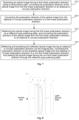
- the invention further provides a short-distance optical amplification method, and the method includes the following steps.
- Step S210 an optical image having a first linear polarization direction is output along a transmission path, the polarization direction of the optical image is converted from the first linear polarization direction to an elliptical or circular polarization direction, and the optical image is transmissively amplified via an imaging lens.
- Step S220 the polarization direction of the optical image is converted from the elliptical or circular polarization direction to a first linear polarization direction.
- Step S230 the optical image having the first linear polarization direction is reflected via a reflective type polarizing plate, and the polarization direction of the optical image is converted from the first linear polarization direction to an elliptical or circular polarization direction, wherein, the reflective type polarizing plate has a transmission direction orthogonal to the first linear polarization direction.
- Step S240 the reflected optical image having an elliptical or circular polarization direction is reflectively amplified via the imaging lens, the polarization direction of the amplified optical image is converted from the elliptical or circular polarization direction to a non-first linear polarization direction, and the optical image having the non-first linear polarization direction is passed through the reflective type polarizing plate.
- the invention further provides a short-distance optical amplification system.
- the system includes an optical display screen 1 configured for generating an optical image having a first linear polarization direction, and a short-distance optical amplification module 10, wherein, the short-distance optical amplification module 10 includes: a first phase delay layer 2, an imaging lens layer 4, a second phase delay layer 5 and a reflective type polarization layer 6, wherein:
- the first phase delay layer 2 is arranged in a transmission path of an optical image having a first linear polarization direction and is configured for converting the polarization direction of the optical image from the first linear polarization direction to an elliptical or circular polarization direction;
- the imaging lens layer 4 is arranged in a transmission path of an optical image having an elliptical or circular polarization direction and has a first optical surface adjacent to the first phase delay plate 2 and a second optical surface opposite to the first optical surface, the first optical surface being a transflective optical surface, and the imaging lens 4 is configured for amplifying an optical image passing through the first optical surface;
- the second phase delay layer 5 is arranged on one side of the second optical surface of the imaging lens 4 and is configured for converting the polarization direction of the optical image from the elliptical or circular polarization direction to a second linear polarization direction, wherein the second linear polarization direction is orthogonal to the first linear polarization direction;
- the reflective type polarization layer 6 is adhered to the second phase delay layer 5, and the reflective type polarization layer 6 has a transmission direction consistent with the first linear polarization direction.
- the optical display screen 1 is arranged on one side of the first phase delay layer 2 that is adjacent to the short-distance optical amplification module 10.
- the optical image successively passes through the first phase delay layer, the imaging lens layer, the second phase delay layer and the reflective type polarization layer.
- the reflective type polarization layer is configured for reflecting an optical image having a second linear polarization direction that is transmitted from the second phase delay layer.
- the imaging lens layer is configured for reflecting and again amplifying the optical image reflected by the reflective type polarization layer.
- the second phase delay layer is further configured for converting the polarization direction of the amplified optical image into a non-second linear polarization direction, thereby passing an optical image having the non-second linear polarization direction through the reflective type polarizing plate.
- the structural positions and functions of the first phase delay layer, the imaging lens layer, the second phase delay layer and the reflective type polarization layer in the short-distance optical amplification system according to this embodiment are respectively the same as the structural positions and functions of the first phase delay layer, the imaging lens layer, the second phase delay layer and the reflective type polarization layer in the above embodiment, and the transmission process of the optical image in the short-distance optical amplification module 10 is also the same as that in the above short-distance optical amplification module.
- the short-distance optical amplification module is a multilayer optical structure consisted of a first phase delay layer, an imaging lens layer, a second phase delay layer and a reflective type polarization layer, and the size and volume of the optical amplification module are greatly reduced without affecting the optical imaging quality, the weight is reduced, and the comfortableness of wearing VR glasses employing the optical amplification component is improved.
- the short-distance optical amplification module 10 in the optical amplification system further includes an absorptive type polarization layer 7, wherein, the absorptive type polarization layer 7 is arranged on one side that is adjacent to the reflective polarization layer 6 and faces away from the second phase delay layer 5, and the absorptive type polarization layer can absorb the light from the outside and prevent a reflection image of the outside from being seen, thereby preventing the interference of the ambient light on the display.
- the system further includes an optical device 3 that will not affect the phase delay, wherein, the optical device 3 is arranged between any two of the optical display screen, the first phase delay layer, the imaging lens layer, the second phase delay layer and the reflective polarization layer.
- the optical device 3 that will not affect the phase delay is arranged between the first phase delay layer 2 and the optical display screen 1 and is integrated with the short-distance optical amplification module 10.
- the optical device includes a near-sighted lens, a far-sighted lens or , in an example, which does not fall under the scope of the claims, an astigmatic lens thereby improving the applicability of the short-distance optical amplification module.
- the two sides of the optical display screen 1 are both flat surfaces.
- the first phase delay plate 2 is adhered to the optical display screen 1.
- the first phase delay plate and the second phase delay plate are both 1/4 wave plates.
Landscapes
- Physics & Mathematics (AREA)
- General Physics & Mathematics (AREA)
- Optics & Photonics (AREA)
- Polarising Elements (AREA)
- Projection Apparatus (AREA)
- Lenses (AREA)
Claims (6)
- Optisches Kurzstreckenverstärkungssystem, umfassend: einen optischen Anzeigebildschirm (1), eine erste Phasenverzögerungsplatte (2), eine konvexe Abbildungslinse (4), eine zweite Phasenverzögerungsplatte (5) und eine Polarisationsplatte (6) vom Reflexionstyp, die nacheinander eingerichtet sind, wobei:die erste Phasenverzögerungsplatte (2) in einem Übertragungsweg eines optischen Bilds mit einer ersten linearen Polarisationsrichtung eingerichtet ist und zum Umwandeln der Polarisationsrichtung des optischen Bilds von der ersten linearen Polarisationsrichtung in eine elliptische oder zirkulare Polarisationsrichtung konfiguriert ist;die konvexe Abbildungslinse (4) in einem Übertragungsweg eines optischen Bilds mit einer elliptischen oder zirkularen Polarisationsrichtung eingerichtet ist und die konvexe Abbildungslinse (4) eine erste optische Fläche und eine zweite optische Fläche, die entgegengesetzt zu der ersten optischen Fläche ist, aufweist, wobei die erste optische Fläche eine transflektive optische Fläche ist, wobei die erste optische Fläche eine gekrümmte Fläche ist, die zweite optische Fläche eine flache Fläche ist und die Mitte der Krümmung der ersten optischen Fläche und die zweite optische Fläche auf derselben Seite der ersten optischen Fläche angeordnet sind, und die konvexe Abbildungslinse (4) zum übertragenden Verstärken eines optischen Bilds, das durch die erste optische Fläche hindurchtritt, zum ersten Mal konfiguriert ist;die zweite Phasenverzögerungsplatte (5) auf einer Seite der zweiten optischen Fläche der konvexen Abbildungslinse eingerichtet ist und zum Umwandeln der Polarisationsrichtung des optischen Bilds von der elliptischen oder zirkularen Polarisationsrichtung in die erste lineare Polarisationsrichtung konfiguriert ist;die Polarisationsplatte (6) vom Reflexionstyp an der zweiten Phasenverzögerungsplatte angehaftet ist und die Polarisationsplatte (6) vom Reflexionstyp eine Übertragungsrichtung aufweist, die orthogonal zu der ersten linearen Polarisationsrichtung ist;wobei die Richtung eines polarisierten Lichts, das von der ersten Phasenverzögerungsplatte (2) gedreht wird, entgegengesetzt zu dem ist, das von der zweiten Phasenverzögerungsplatte (5) gedreht wird;wobei das optische Bild nacheinander durch die erste Phasenverzögerungsplatte (2), die konvexe Abbildungslinse (4), die zweite Phasenverzögerungsplatte (5) hindurchtritt, um die Polarisationsplatte (6) vom Reflexionstyp zu erreichen, wobei ein optisches Bild mit einer ersten linearen Polarisationsrichtung, das von der zweiten Phasenverzögerungsplatte (5) übertragen wird, von der Polarisationsplatte vom Reflexionstyp reflektiert wird, durch die zweite Phasenverzögerungsplatte hindurchtritt, um die erste optische Fläche der konvexen Abbildungslinse (4) zu erreichen, wobei die erste optische Fläche der konvexen Abbildungslinse (4) das optische Bild, das von der Polarisationsplatte (6) vom Reflexionstyp reflektiert wird, zum zweiten Mal reflektierend verstärkt, wobei das so reflektierte Bild nacheinander durch die konvexe Abbildungslinse (4), die zweite Phasenverzögerungsplatte (5) hindurchtritt, um die Polarisationsplatte (6) vom Reflexionstyp zu erreichen, und die zweite Phasenverzögerungsplatte (5) weiterhin die Polarisationsrichtung des optischen Bilds, das zum zweiten Mal reflektierend verstärkt wurde, in eine nicht-erste lineare Polarisationsrichtung umwandelt, wodurch das optische Bild mit der nicht-ersten linearen Polarisationsrichtung durch die Polarisationsplatte (6) vom Reflexionstyp hindurchtritt,wobei die zweite reflektierende Verstärkung größer als die erste übertragende Verstärkung ist, dadurch gekennzeichnet, dass:die erste optische Fläche angrenzend zu der ersten Phasenverzögerungsplatte ist;wobei das optische Kurzstreckenverstärkungssystem weiterhin eine optische Vorrichtung umfasst, die eine Phasenverzögerung nicht beeinflussen wird, eingerichtet zwischen beliebigen zwei von dem optischen Anzeigebildschirm, der ersten Phasenverzögerungsplatte (2), der konvexen Abbildungslinse (4), der zweiten Phasenverzögerungsplatte (5) und der Polarisationsplatte (6) vom Reflexionstyp, wobei die optische Vorrichtung eine Kurzsichtlinse oder eine Weitsichtlinse umfasst.
- System nach Anspruch 1, wobei die nicht-erste lineare Polarisationsrichtung orthogonal zu der ersten linearen Polarisationsrichtung ist.
- System nach Anspruch 1, wobei die zweite Phasenverzögerungsplatte (5) an der zweiten optischen Fläche der konvexen Abbildungslinse (4) angehaftet ist.
- System nach Anspruch 2, weiterhin umfassend: eine Polarisationsplatte (7) vom Absorptionstyp;
wobei die Polarisationsplatte vom Absorptionstyp an einer Seite der Polarisationsplatte (6) vom Reflexionstyp angehaftet ist, die von der konvexen Abbildungslinse (4) weg weist, und die Polarisationsplatte (7) vom Absorptionstyp eine Übertragungsrichtung aufweist, die mit der Polarisationsplatte (6) vom Reflexionstyp übereinstimmt. - System nach einem der Ansprüche 1 bis 4, wobei der optische Anzeigebildschirm (1) zum Erzeugen eines optischen Bilds mit der ersten linearen Polarisationsrichtung konfiguriert ist und an der ersten Phasenverzögerungsplatte (2) angehaftet ist.
- Optisches Kurzstreckenverstärkungsverfahren, umfassend die Schritte:Ausgeben (S210) eines optischen Bilds mit einer ersten linearen Polarisationsrichtung durch einen optischen Anzeigebildschirm (1) entlang einem Übertragungsweg, Umwandeln der Polarisationsrichtung des optischen Bilds von der ersten linearen Polarisationsrichtung in eine elliptische oder zirkulare Polarisationsrichtung mittels einer ersten Phasenverzögerungsplatte und Übertragen und übertragendes Verstärken des optischen Bilds zum ersten Mal mittels einer konvexen Abbildungslinse (4), wobei die konvexe Abbildungslinse (4) eine erste optische Fläche und eine zweite optische Fläche, die entgegengesetzt zu der ersten optischen Fläche ist, aufweist, wobei die erste optische Fläche eine transflektive optische Fläche ist, wobei die erste optische Fläche eine gekrümmte Fläche ist, die zweite optische Fläche eine flache Fläche ist und die Mitte der Krümmung der ersten optischen Fläche und die zweite optische Fläche auf derselben Seite der ersten optischen Fläche angeordnet sind;Umwandeln (S220) der Polarisationsrichtung des optischen Bilds von der elliptischen oder zirkularen Polarisationsrichtung in eine erste lineare Polarisationsrichtung mittels einer zweiten Phasenverzögerungsplatte (5), wobei die Richtung eines polarisierten Lichts, das von der ersten Phasenverzögerungsplatte (2) gedreht wird, entgegengesetzt zu dem ist, das von der zweiten Phasenverzögerungsplatte (5) gedreht wird, wobei die zweite Phasenverzögerungsplatte auf der Seite der zweiten optischen Fläche der konvexen Abbildungslinse eingerichtet ist;Reflektieren (S230) des optischen Bilds mit der ersten linearen Polarisationsrichtung mittels einer Polarisationsplatte (6) vom Reflexionstyp, die eine Übertragungsrichtung aufweist, die orthogonal zu der ersten linearen Polarisationsrichtung ist, wobei das so reflektierte optische Bild durch die zweite Phasenverzögerungsplatte hindurchtritt, um die erste optische Fläche der konvexen Abbildungslinse zu erreichen, wobei die zweite Phasenverzögerungsplatte die Polarisationsrichtung des optischen Bilds von der ersten linearen Polarisationsrichtung in eine elliptische oder zirkulare Polarisationsrichtung umwandelt; undreflektierendes Verstärken (S240) des reflektierten optischen Bilds mit einer elliptischen oder zirkularen Polarisationsrichtung zum zweiten Mal mittels der ersten optischen Fläche der konvexen Abbildungslinse (4), wobei das so reflektierte Bild nacheinander durch die konvexe Abbildungslinse, die zweite Phasenverzögerungsplatte hindurchtritt, um die Polarisationsplatte vom Reflexionstyp zu erreichen;Umwandeln der Polarisationsrichtung des zum zweiten Mal reflektierend verstärkten optischen Bilds von der elliptischen oder zirkularen Polarisationsrichtung in eine nicht-erste lineare Polarisationsrichtung mittels der zweiten Phasenverzögerungsplatte und Hindurchführen des optischen Bilds mit der nicht-ersten linearen Polarisationsrichtung durch die Polarisationsplatte (6) vom Reflexionstyp,wobei die zweite reflektierende Verstärkung größer als die erste übertragende Verstärkung ist, dadurch gekennzeichnet, dass:die erste optische Fläche angrenzend zu der ersten Phasenverzögerungsplatte ist;wobei eine optische Vorrichtung, die eine Phasenverzögerung nicht beeinflussen wird, weiterhin in dem Übertragungsweg vorgesehen ist, wobei die optische Vorrichtung zwischen beliebigen zwei von dem optischen Anzeigebildschirm, der ersten Phasenverzögerungsplatte (2), der konvexen Abbildungslinse (4), der zweiten Phasenverzögerungsplatte (5) und der Polarisationsplatte (6) vom Reflexionstyp eingerichtet ist und eine Kurzsichtlinse oder eine Weitsichtlinse umfasst.
Applications Claiming Priority (1)
| Application Number | Priority Date | Filing Date | Title |
|---|---|---|---|
| PCT/CN2016/072528 WO2017128183A1 (zh) | 2016-01-28 | 2016-01-28 | 短距离光学放大模组、放大方法及放大系统 |
Publications (3)
| Publication Number | Publication Date |
|---|---|
| EP3410173A1 EP3410173A1 (de) | 2018-12-05 |
| EP3410173A4 EP3410173A4 (de) | 2019-09-18 |
| EP3410173B1 true EP3410173B1 (de) | 2024-11-06 |
Family
ID=59396894
Family Applications (1)
| Application Number | Title | Priority Date | Filing Date |
|---|---|---|---|
| EP16887070.7A Active EP3410173B1 (de) | 2016-01-28 | 2016-01-28 | Optisches verstärkermodul mit kurzer reichweite, verstärkungsverfahren und verstärkungssystem |
Country Status (8)
| Country | Link |
|---|---|
| US (1) | US20190033599A1 (de) |
| EP (1) | EP3410173B1 (de) |
| JP (1) | JP6686178B2 (de) |
| KR (1) | KR102162985B1 (de) |
| ES (1) | ES3005757T3 (de) |
| FI (1) | FI3410173T3 (de) |
| PT (1) | PT3410173T (de) |
| WO (1) | WO2017128183A1 (de) |
Families Citing this family (31)
| Publication number | Priority date | Publication date | Assignee | Title |
|---|---|---|---|---|
| WO2018039273A1 (en) | 2016-08-22 | 2018-03-01 | Magic Leap, Inc. | Dithering methods and apparatus for wearable display device |
| JP7173768B2 (ja) * | 2018-07-04 | 2022-11-16 | キヤノン株式会社 | 電子ビューファインダおよび撮像装置 |
| CN111694157B (zh) * | 2018-08-31 | 2025-07-04 | 华为技术有限公司 | 一种光学成像系统 |
| CN113267890B (zh) * | 2020-02-14 | 2024-10-01 | 东莞双营光电科技有限公司 | 短距离光学系统 |
| CN212111989U (zh) * | 2020-05-27 | 2020-12-08 | 歌尔光学科技有限公司 | 光学系统及虚拟现实设备 |
| CN114967135B (zh) * | 2021-02-25 | 2025-05-13 | 东莞双营光电科技有限公司 | 超短距目镜系统 |
| CN115220224B (zh) * | 2021-04-19 | 2025-05-06 | 东莞双营光电科技有限公司 | 微型化头戴显示器的光学系统 |
| CN114236828B (zh) * | 2021-11-30 | 2023-03-14 | 歌尔光学科技有限公司 | 一种光学系统以及头戴显示设备 |
| JP2023134316A (ja) * | 2022-03-14 | 2023-09-27 | 日東電工株式会社 | レンズ部、積層体、表示体、表示体の製造方法および表示方法 |
| JP7516455B2 (ja) * | 2022-05-10 | 2024-07-16 | 日東電工株式会社 | レンズ部、積層体、表示体、表示体の製造方法および表示方法 |
| JP2023134317A (ja) * | 2022-03-14 | 2023-09-27 | 日東電工株式会社 | 表示システム、表示方法、表示体および表示体の製造方法 |
| WO2023176365A1 (ja) * | 2022-03-14 | 2023-09-21 | 日東電工株式会社 | レンズ部、積層体、表示体、表示体の製造方法および表示方法 |
| US20250208419A1 (en) * | 2022-03-14 | 2025-06-26 | Nitto Denko Corporation | Lens part, laminate, display body, and manufacturing method and display method for display body |
| KR20240156380A (ko) * | 2022-03-14 | 2024-10-29 | 닛토덴코 가부시키가이샤 | 렌즈부, 적층체, 표시체, 표시체의 제조 방법 및 표시 방법 |
| JP7516457B2 (ja) * | 2022-05-10 | 2024-07-16 | 日東電工株式会社 | レンズ部、積層体、表示体、表示体の製造方法および表示方法 |
| US20250199279A1 (en) * | 2022-03-14 | 2025-06-19 | Nitto Denko Corporation | Lens unit, laminate, display body, display body manufacturing method, and display method |
| KR20240153346A (ko) * | 2022-03-14 | 2024-10-22 | 닛토덴코 가부시키가이샤 | 표시 시스템, 표시 방법, 표시체 및 표시체의 제조 방법 |
| JP2023166851A (ja) * | 2022-05-10 | 2023-11-22 | 日東電工株式会社 | レンズ部、積層体、表示体、表示体の製造方法および表示方法 |
| JP2023166853A (ja) * | 2022-05-10 | 2023-11-22 | 日東電工株式会社 | レンズ部、積層体、表示体、表示体の製造方法および表示方法 |
| KR20240155215A (ko) * | 2022-03-14 | 2024-10-28 | 닛토덴코 가부시키가이샤 | 표시 방법 |
| WO2023176363A1 (ja) * | 2022-03-14 | 2023-09-21 | 日東電工株式会社 | 表示システム、表示方法、表示体および表示体の製造方法 |
| JP2023166852A (ja) * | 2022-05-10 | 2023-11-22 | 日東電工株式会社 | レンズ部、積層体、表示体、表示体の製造方法および表示方法 |
| KR20240155253A (ko) * | 2022-03-14 | 2024-10-28 | 닛토덴코 가부시키가이샤 | 렌즈부, 적층체, 표시체, 표시체의 제조 방법 및 표시 방법 |
| WO2023176357A1 (ja) * | 2022-03-14 | 2023-09-21 | 日東電工株式会社 | レンズ部、積層体、表示体、表示体の製造方法および表示方法 |
| JP7516458B2 (ja) * | 2022-05-10 | 2024-07-16 | 日東電工株式会社 | レンズ部、積層体、表示体、表示体の製造方法および表示方法 |
| WO2023176366A1 (ja) * | 2022-03-14 | 2023-09-21 | 日東電工株式会社 | レンズ部、積層体、表示体、表示体の製造方法および表示方法 |
| JP7516456B2 (ja) * | 2022-05-10 | 2024-07-16 | 日東電工株式会社 | 表示方法 |
| KR20240156375A (ko) * | 2022-03-14 | 2024-10-29 | 닛토덴코 가부시키가이샤 | 표시 시스템, 표시 방법, 표시체 및 표시체의 제조 방법 |
| CN117008238A (zh) * | 2022-04-28 | 2023-11-07 | 北京字跳网络技术有限公司 | 光学偏振器件及其制造方法、近眼显示设备 |
| CN115407508B (zh) * | 2022-07-26 | 2025-08-19 | 歌尔光学科技有限公司 | 光学模组以及头戴显示设备 |
| CN118112794A (zh) * | 2022-11-30 | 2024-05-31 | 北京字跳网络技术有限公司 | 光学结构以及显示装置 |
Citations (3)
| Publication number | Priority date | Publication date | Assignee | Title |
|---|---|---|---|---|
| US5966242A (en) * | 1996-04-24 | 1999-10-12 | Sharp Kabushiki Kaisha | Optical device and HMD using said optical device |
| EP1096293A2 (de) * | 1999-10-26 | 2001-05-02 | Agilent Technologies Inc | Gefaltetes optisches System für eine kopfmontierte Anzeigevorrichtung |
| US20150219893A1 (en) * | 2013-02-07 | 2015-08-06 | Liqxtal Technology Inc. | Optical system and its display system |
Family Cites Families (12)
| Publication number | Priority date | Publication date | Assignee | Title |
|---|---|---|---|---|
| JP3295583B2 (ja) * | 1994-12-19 | 2002-06-24 | シャープ株式会社 | 光学装置および該光学装置を用いた頭部搭載型ディスプレイ |
| US5715023A (en) * | 1996-04-30 | 1998-02-03 | Kaiser Electro-Optics, Inc. | Plane parallel optical collimating device employing a cholesteric liquid crystal |
| US6075651A (en) * | 1999-01-28 | 2000-06-13 | Kaiser Electro-Optics, Inc. | Compact collimating apparatus |
| JP2000249984A (ja) * | 1999-02-26 | 2000-09-14 | Minolta Co Ltd | 反射透過偏光子を用いた光学系 |
| CN1316063A (zh) * | 1999-07-02 | 2001-10-03 | 皇家菲利浦电子有限公司 | 头戴型显示器 |
| US6563638B2 (en) * | 2001-04-26 | 2003-05-13 | Raytheon Company | Wide-angle collimating optical device |
| US6853491B1 (en) * | 2003-11-26 | 2005-02-08 | Frank Ruhle | Collimating optical member for real world simulation |
| KR20120126561A (ko) * | 2011-05-12 | 2012-11-21 | 엘지디스플레이 주식회사 | 영상 표시장치 |
| CN204855955U (zh) * | 2015-07-13 | 2015-12-09 | 深圳多新哆技术有限责任公司 | 短距离光学放大模组及使用其的近眼显示光学模组 |
| CN105093555B (zh) * | 2015-07-13 | 2018-08-14 | 深圳多新哆技术有限责任公司 | 短距离光学放大模组及使用其的近眼显示光学模组 |
| CN205539752U (zh) * | 2016-01-28 | 2016-08-31 | 深圳多哚新技术有限责任公司 | 短距离光学放大模组及其组件 |
| CN105629472A (zh) * | 2016-01-28 | 2016-06-01 | 深圳多哚新技术有限责任公司 | 短距离光学放大模组、放大方法及放大系统 |
-
2016
- 2016-01-28 JP JP2018558458A patent/JP6686178B2/ja active Active
- 2016-01-28 FI FIEP16887070.7T patent/FI3410173T3/fi active
- 2016-01-28 US US16/073,306 patent/US20190033599A1/en not_active Abandoned
- 2016-01-28 PT PT168870707T patent/PT3410173T/pt unknown
- 2016-01-28 EP EP16887070.7A patent/EP3410173B1/de active Active
- 2016-01-28 WO PCT/CN2016/072528 patent/WO2017128183A1/zh not_active Ceased
- 2016-01-28 KR KR1020187024656A patent/KR102162985B1/ko active Active
- 2016-01-28 ES ES16887070T patent/ES3005757T3/es active Active
Patent Citations (3)
| Publication number | Priority date | Publication date | Assignee | Title |
|---|---|---|---|---|
| US5966242A (en) * | 1996-04-24 | 1999-10-12 | Sharp Kabushiki Kaisha | Optical device and HMD using said optical device |
| EP1096293A2 (de) * | 1999-10-26 | 2001-05-02 | Agilent Technologies Inc | Gefaltetes optisches System für eine kopfmontierte Anzeigevorrichtung |
| US20150219893A1 (en) * | 2013-02-07 | 2015-08-06 | Liqxtal Technology Inc. | Optical system and its display system |
Non-Patent Citations (1)
| Title |
|---|
| ANONYMOUS: "Aspheric lens - Wikipedia", 23 November 2015 (2015-11-23), XP093162728, Retrieved from the Internet <URL:https://en.wikipedia.org/w/index.php?title=Aspheric_lens&oldid=691931549> * |
Also Published As
| Publication number | Publication date |
|---|---|
| EP3410173A1 (de) | 2018-12-05 |
| US20190033599A1 (en) | 2019-01-31 |
| KR102162985B1 (ko) | 2020-10-08 |
| PT3410173T (pt) | 2025-01-27 |
| JP2019505854A (ja) | 2019-02-28 |
| JP6686178B2 (ja) | 2020-04-22 |
| ES3005757T3 (en) | 2025-03-17 |
| EP3410173A4 (de) | 2019-09-18 |
| KR20180105698A (ko) | 2018-09-28 |
| WO2017128183A1 (zh) | 2017-08-03 |
| FI3410173T3 (fi) | 2025-01-16 |
Similar Documents
| Publication | Publication Date | Title |
|---|---|---|
| EP3410173B1 (de) | Optisches verstärkermodul mit kurzer reichweite, verstärkungsverfahren und verstärkungssystem | |
| JP5973098B1 (ja) | ニア・アイ・ディスプレイ用光学モジュール | |
| US6075651A (en) | Compact collimating apparatus | |
| CN111694157B (zh) | 一种光学成像系统 | |
| US6271969B1 (en) | Folded optical system having improved image isolation | |
| CN105572894B (zh) | 一种短距离光学放大模组、放大方法及放大系统 | |
| US11604349B2 (en) | Short-distance optical amplification module, amplification method and amplification system | |
| CN205539752U (zh) | 短距离光学放大模组及其组件 | |
| WO2005054906B1 (en) | Improved collimating optical member for real world simulation | |
| CN204855955U (zh) | 短距离光学放大模组及使用其的近眼显示光学模组 | |
| CN105629472A (zh) | 短距离光学放大模组、放大方法及放大系统 | |
| WO2007139900A2 (en) | Wide field of view, compact collimating apparatus | |
| CN205539751U (zh) | 一种短距离光学放大模组及其组件 | |
| CN114942489A (zh) | 一种光学模组以及头戴显示设备 | |
| CN210776039U (zh) | 微型化短距离光学系统 | |
| CN111474715A (zh) | 光学系统及增强现实设备 | |
| CN108594441A (zh) | 一种光学系统 | |
| CN110646942A (zh) | 一种超薄光学放大模组及其应用 | |
| US20230176381A1 (en) | Augmented reality display system and ar goggle | |
| CN117647895A (zh) | 光学模组以及近眼显示装置 | |
| CN216248599U (zh) | 增强现实显示系统及ar眼镜 | |
| CN117031747A (zh) | 光学模组以及头戴显示设备 | |
| CN112505920A (zh) | 微型化短距离光学系统 | |
| CN215116991U (zh) | 一种增强现实显示系统及增强现实显示设备 | |
| WO2019119258A1 (zh) | 光学系统及近眼显示装置 |
Legal Events
| Date | Code | Title | Description |
|---|---|---|---|
| STAA | Information on the status of an ep patent application or granted ep patent |
Free format text: STATUS: THE INTERNATIONAL PUBLICATION HAS BEEN MADE |
|
| PUAI | Public reference made under article 153(3) epc to a published international application that has entered the european phase |
Free format text: ORIGINAL CODE: 0009012 |
|
| STAA | Information on the status of an ep patent application or granted ep patent |
Free format text: STATUS: REQUEST FOR EXAMINATION WAS MADE |
|
| 17P | Request for examination filed |
Effective date: 20180731 |
|
| AK | Designated contracting states |
Kind code of ref document: A1 Designated state(s): AL AT BE BG CH CY CZ DE DK EE ES FI FR GB GR HR HU IE IS IT LI LT LU LV MC MK MT NL NO PL PT RO RS SE SI SK SM TR |
|
| AX | Request for extension of the european patent |
Extension state: BA ME |
|
| RIN1 | Information on inventor provided before grant (corrected) |
Inventor name: TANG, WEIPING Inventor name: LI, GANG |
|
| DAV | Request for validation of the european patent (deleted) | ||
| DAX | Request for extension of the european patent (deleted) | ||
| A4 | Supplementary search report drawn up and despatched |
Effective date: 20190816 |
|
| RIC1 | Information provided on ipc code assigned before grant |
Ipc: G02B 27/28 20060101ALI20190809BHEP Ipc: G02B 27/01 20060101AFI20190809BHEP Ipc: G02B 5/30 20060101ALI20190809BHEP Ipc: G02B 5/00 20060101ALI20190809BHEP Ipc: G02B 27/00 20060101ALI20190809BHEP |
|
| STAA | Information on the status of an ep patent application or granted ep patent |
Free format text: STATUS: EXAMINATION IS IN PROGRESS |
|
| 17Q | First examination report despatched |
Effective date: 20200807 |
|
| GRAP | Despatch of communication of intention to grant a patent |
Free format text: ORIGINAL CODE: EPIDOSNIGR1 |
|
| STAA | Information on the status of an ep patent application or granted ep patent |
Free format text: STATUS: GRANT OF PATENT IS INTENDED |
|
| RIC1 | Information provided on ipc code assigned before grant |
Ipc: G02B 17/08 20060101ALI20240521BHEP Ipc: G02B 27/00 20060101ALI20240521BHEP Ipc: G02B 27/28 20060101ALI20240521BHEP Ipc: G02B 5/30 20060101ALI20240521BHEP Ipc: G02B 5/00 20060101ALI20240521BHEP Ipc: G02B 27/01 20060101AFI20240521BHEP |
|
| INTG | Intention to grant announced |
Effective date: 20240605 |
|
| GRAS | Grant fee paid |
Free format text: ORIGINAL CODE: EPIDOSNIGR3 |
|
| GRAA | (expected) grant |
Free format text: ORIGINAL CODE: 0009210 |
|
| STAA | Information on the status of an ep patent application or granted ep patent |
Free format text: STATUS: THE PATENT HAS BEEN GRANTED |
|
| P01 | Opt-out of the competence of the unified patent court (upc) registered |
Free format text: CASE NUMBER: APP_51836/2024 Effective date: 20240916 |
|
| AK | Designated contracting states |
Kind code of ref document: B1 Designated state(s): AL AT BE BG CH CY CZ DE DK EE ES FI FR GB GR HR HU IE IS IT LI LT LU LV MC MK MT NL NO PL PT RO RS SE SI SK SM TR |
|
| REG | Reference to a national code |
Ref country code: GB Ref legal event code: FG4D |
|
| REG | Reference to a national code |
Ref country code: CH Ref legal event code: EP |
|
| REG | Reference to a national code |
Ref country code: DE Ref legal event code: R096 Ref document number: 602016090170 Country of ref document: DE |
|
| REG | Reference to a national code |
Ref country code: IE Ref legal event code: FG4D |
|
| REG | Reference to a national code |
Ref country code: FI Ref legal event code: FGE |
|
| REG | Reference to a national code |
Ref country code: PT Ref legal event code: SC4A Ref document number: 3410173 Country of ref document: PT Date of ref document: 20250127 Kind code of ref document: T Free format text: AVAILABILITY OF NATIONAL TRANSLATION Effective date: 20250122 |
|
| REG | Reference to a national code |
Ref country code: SE Ref legal event code: TRGR |
|
| REG | Reference to a national code |
Ref country code: NL Ref legal event code: FP |
|
| REG | Reference to a national code |
Ref country code: LT Ref legal event code: MG9D |
|
| REG | Reference to a national code |
Ref country code: ES Ref legal event code: FG2A Ref document number: 3005757 Country of ref document: ES Kind code of ref document: T3 Effective date: 20250317 |
|
| PG25 | Lapsed in a contracting state [announced via postgrant information from national office to epo] |
Ref country code: IS Free format text: LAPSE BECAUSE OF FAILURE TO SUBMIT A TRANSLATION OF THE DESCRIPTION OR TO PAY THE FEE WITHIN THE PRESCRIBED TIME-LIMIT Effective date: 20250306 Ref country code: HR Free format text: LAPSE BECAUSE OF FAILURE TO SUBMIT A TRANSLATION OF THE DESCRIPTION OR TO PAY THE FEE WITHIN THE PRESCRIBED TIME-LIMIT Effective date: 20241106 |
|
| REG | Reference to a national code |
Ref country code: AT Ref legal event code: MK05 Ref document number: 1739993 Country of ref document: AT Kind code of ref document: T Effective date: 20241106 |
|
| PG25 | Lapsed in a contracting state [announced via postgrant information from national office to epo] |
Ref country code: BG Free format text: LAPSE BECAUSE OF FAILURE TO SUBMIT A TRANSLATION OF THE DESCRIPTION OR TO PAY THE FEE WITHIN THE PRESCRIBED TIME-LIMIT Effective date: 20241106 |
|
| PG25 | Lapsed in a contracting state [announced via postgrant information from national office to epo] |
Ref country code: NO Free format text: LAPSE BECAUSE OF FAILURE TO SUBMIT A TRANSLATION OF THE DESCRIPTION OR TO PAY THE FEE WITHIN THE PRESCRIBED TIME-LIMIT Effective date: 20250206 |
|
| PG25 | Lapsed in a contracting state [announced via postgrant information from national office to epo] |
Ref country code: AT Free format text: LAPSE BECAUSE OF FAILURE TO SUBMIT A TRANSLATION OF THE DESCRIPTION OR TO PAY THE FEE WITHIN THE PRESCRIBED TIME-LIMIT Effective date: 20241106 Ref country code: LV Free format text: LAPSE BECAUSE OF FAILURE TO SUBMIT A TRANSLATION OF THE DESCRIPTION OR TO PAY THE FEE WITHIN THE PRESCRIBED TIME-LIMIT Effective date: 20241106 Ref country code: GR Free format text: LAPSE BECAUSE OF FAILURE TO SUBMIT A TRANSLATION OF THE DESCRIPTION OR TO PAY THE FEE WITHIN THE PRESCRIBED TIME-LIMIT Effective date: 20250207 |
|
| PG25 | Lapsed in a contracting state [announced via postgrant information from national office to epo] |
Ref country code: PL Free format text: LAPSE BECAUSE OF FAILURE TO SUBMIT A TRANSLATION OF THE DESCRIPTION OR TO PAY THE FEE WITHIN THE PRESCRIBED TIME-LIMIT Effective date: 20241106 |
|
| PG25 | Lapsed in a contracting state [announced via postgrant information from national office to epo] |
Ref country code: RS Free format text: LAPSE BECAUSE OF FAILURE TO SUBMIT A TRANSLATION OF THE DESCRIPTION OR TO PAY THE FEE WITHIN THE PRESCRIBED TIME-LIMIT Effective date: 20250206 |
|
| PG25 | Lapsed in a contracting state [announced via postgrant information from national office to epo] |
Ref country code: SM Free format text: LAPSE BECAUSE OF FAILURE TO SUBMIT A TRANSLATION OF THE DESCRIPTION OR TO PAY THE FEE WITHIN THE PRESCRIBED TIME-LIMIT Effective date: 20241106 |
|
| PG25 | Lapsed in a contracting state [announced via postgrant information from national office to epo] |
Ref country code: DK Free format text: LAPSE BECAUSE OF FAILURE TO SUBMIT A TRANSLATION OF THE DESCRIPTION OR TO PAY THE FEE WITHIN THE PRESCRIBED TIME-LIMIT Effective date: 20241106 |
|
| PG25 | Lapsed in a contracting state [announced via postgrant information from national office to epo] |
Ref country code: EE Free format text: LAPSE BECAUSE OF FAILURE TO SUBMIT A TRANSLATION OF THE DESCRIPTION OR TO PAY THE FEE WITHIN THE PRESCRIBED TIME-LIMIT Effective date: 20241106 |
|
| PG25 | Lapsed in a contracting state [announced via postgrant information from national office to epo] |
Ref country code: RO Free format text: LAPSE BECAUSE OF FAILURE TO SUBMIT A TRANSLATION OF THE DESCRIPTION OR TO PAY THE FEE WITHIN THE PRESCRIBED TIME-LIMIT Effective date: 20241106 |
|
| PG25 | Lapsed in a contracting state [announced via postgrant information from national office to epo] |
Ref country code: SK Free format text: LAPSE BECAUSE OF FAILURE TO SUBMIT A TRANSLATION OF THE DESCRIPTION OR TO PAY THE FEE WITHIN THE PRESCRIBED TIME-LIMIT Effective date: 20241106 |
|
| PG25 | Lapsed in a contracting state [announced via postgrant information from national office to epo] |
Ref country code: CZ Free format text: LAPSE BECAUSE OF FAILURE TO SUBMIT A TRANSLATION OF THE DESCRIPTION OR TO PAY THE FEE WITHIN THE PRESCRIBED TIME-LIMIT Effective date: 20241106 |
|
| REG | Reference to a national code |
Ref country code: DE Ref legal event code: R097 Ref document number: 602016090170 Country of ref document: DE |
|
| PLBE | No opposition filed within time limit |
Free format text: ORIGINAL CODE: 0009261 |
|
| STAA | Information on the status of an ep patent application or granted ep patent |
Free format text: STATUS: NO OPPOSITION FILED WITHIN TIME LIMIT |
|
| PG25 | Lapsed in a contracting state [announced via postgrant information from national office to epo] |
Ref country code: MC Free format text: LAPSE BECAUSE OF FAILURE TO SUBMIT A TRANSLATION OF THE DESCRIPTION OR TO PAY THE FEE WITHIN THE PRESCRIBED TIME-LIMIT Effective date: 20241106 Ref country code: LU Free format text: LAPSE BECAUSE OF NON-PAYMENT OF DUE FEES Effective date: 20250128 |
|
| 26N | No opposition filed |
Effective date: 20250807 |
|
| REG | Reference to a national code |
Ref country code: CH Ref legal event code: U11 Free format text: ST27 STATUS EVENT CODE: U-0-0-U10-U11 (AS PROVIDED BY THE NATIONAL OFFICE) Effective date: 20260201 |
|
| PGFP | Annual fee paid to national office [announced via postgrant information from national office to epo] |
Ref country code: NL Payment date: 20260121 Year of fee payment: 11 |
|
| PGFP | Annual fee paid to national office [announced via postgrant information from national office to epo] |
Ref country code: SE Payment date: 20260121 Year of fee payment: 11 |
|
| PGFP | Annual fee paid to national office [announced via postgrant information from national office to epo] |
Ref country code: GB Payment date: 20260123 Year of fee payment: 11 |
|
| PGFP | Annual fee paid to national office [announced via postgrant information from national office to epo] |
Ref country code: ES Payment date: 20260227 Year of fee payment: 11 |
|
| PGFP | Annual fee paid to national office [announced via postgrant information from national office to epo] |
Ref country code: DE Payment date: 20260121 Year of fee payment: 11 Ref country code: IE Payment date: 20260122 Year of fee payment: 11 |
|
| PGFP | Annual fee paid to national office [announced via postgrant information from national office to epo] |
Ref country code: FI Payment date: 20260129 Year of fee payment: 11 Ref country code: IT Payment date: 20260126 Year of fee payment: 11 Ref country code: BE Payment date: 20260121 Year of fee payment: 11 |
|
| PGFP | Annual fee paid to national office [announced via postgrant information from national office to epo] |
Ref country code: FR Payment date: 20260123 Year of fee payment: 11 |
|
| PGFP | Annual fee paid to national office [announced via postgrant information from national office to epo] |
Ref country code: CH Payment date: 20260201 Year of fee payment: 11 Ref country code: PT Payment date: 20260115 Year of fee payment: 11 |