EP3409592A1 - Shock-absorbing structure, pan-tilt assembly using same, and unmanned aerial vehicle - Google Patents
Shock-absorbing structure, pan-tilt assembly using same, and unmanned aerial vehicle Download PDFInfo
- Publication number
- EP3409592A1 EP3409592A1 EP16886948.5A EP16886948A EP3409592A1 EP 3409592 A1 EP3409592 A1 EP 3409592A1 EP 16886948 A EP16886948 A EP 16886948A EP 3409592 A1 EP3409592 A1 EP 3409592A1
- Authority
- EP
- European Patent Office
- Prior art keywords
- shock
- pan
- tilt
- absorbing
- hole
- Prior art date
- Legal status (The legal status is an assumption and is not a legal conclusion. Google has not performed a legal analysis and makes no representation as to the accuracy of the status listed.)
- Granted
Links
Images




Classifications
-
- F—MECHANICAL ENGINEERING; LIGHTING; HEATING; WEAPONS; BLASTING
- F16—ENGINEERING ELEMENTS AND UNITS; GENERAL MEASURES FOR PRODUCING AND MAINTAINING EFFECTIVE FUNCTIONING OF MACHINES OR INSTALLATIONS; THERMAL INSULATION IN GENERAL
- F16F—SPRINGS; SHOCK-ABSORBERS; MEANS FOR DAMPING VIBRATION
- F16F15/00—Suppression of vibrations in systems; Means or arrangements for avoiding or reducing out-of-balance forces, e.g. due to motion
- F16F15/02—Suppression of vibrations of non-rotating, e.g. reciprocating systems; Suppression of vibrations of rotating systems by use of members not moving with the rotating systems
- F16F15/04—Suppression of vibrations of non-rotating, e.g. reciprocating systems; Suppression of vibrations of rotating systems by use of members not moving with the rotating systems using elastic means
-
- B—PERFORMING OPERATIONS; TRANSPORTING
- B64—AIRCRAFT; AVIATION; COSMONAUTICS
- B64U—UNMANNED AERIAL VEHICLES [UAV]; EQUIPMENT THEREFOR
- B64U20/00—Constructional aspects of UAVs
- B64U20/80—Arrangement of on-board electronics, e.g. avionics systems or wiring
- B64U20/87—Mounting of imaging devices, e.g. mounting of gimbals
-
- F—MECHANICAL ENGINEERING; LIGHTING; HEATING; WEAPONS; BLASTING
- F16—ENGINEERING ELEMENTS AND UNITS; GENERAL MEASURES FOR PRODUCING AND MAINTAINING EFFECTIVE FUNCTIONING OF MACHINES OR INSTALLATIONS; THERMAL INSULATION IN GENERAL
- F16F—SPRINGS; SHOCK-ABSORBERS; MEANS FOR DAMPING VIBRATION
- F16F15/00—Suppression of vibrations in systems; Means or arrangements for avoiding or reducing out-of-balance forces, e.g. due to motion
- F16F15/02—Suppression of vibrations of non-rotating, e.g. reciprocating systems; Suppression of vibrations of rotating systems by use of members not moving with the rotating systems
-
- G—PHYSICS
- G03—PHOTOGRAPHY; CINEMATOGRAPHY; ANALOGOUS TECHNIQUES USING WAVES OTHER THAN OPTICAL WAVES; ELECTROGRAPHY; HOLOGRAPHY
- G03B—APPARATUS OR ARRANGEMENTS FOR TAKING PHOTOGRAPHS OR FOR PROJECTING OR VIEWING THEM; APPARATUS OR ARRANGEMENTS EMPLOYING ANALOGOUS TECHNIQUES USING WAVES OTHER THAN OPTICAL WAVES; ACCESSORIES THEREFOR
- G03B15/00—Special procedures for taking photographs; Apparatus therefor
- G03B15/006—Apparatus mounted on flying objects
-
- G—PHYSICS
- G03—PHOTOGRAPHY; CINEMATOGRAPHY; ANALOGOUS TECHNIQUES USING WAVES OTHER THAN OPTICAL WAVES; ELECTROGRAPHY; HOLOGRAPHY
- G03B—APPARATUS OR ARRANGEMENTS FOR TAKING PHOTOGRAPHS OR FOR PROJECTING OR VIEWING THEM; APPARATUS OR ARRANGEMENTS EMPLOYING ANALOGOUS TECHNIQUES USING WAVES OTHER THAN OPTICAL WAVES; ACCESSORIES THEREFOR
- G03B17/00—Details of cameras or camera bodies; Accessories therefor
- G03B17/56—Accessories
- G03B17/561—Support related camera accessories
-
- H—ELECTRICITY
- H04—ELECTRIC COMMUNICATION TECHNIQUE
- H04N—PICTORIAL COMMUNICATION, e.g. TELEVISION
- H04N23/00—Cameras or camera modules comprising electronic image sensors; Control thereof
- H04N23/50—Constructional details
- H04N23/51—Housings
-
- B—PERFORMING OPERATIONS; TRANSPORTING
- B64—AIRCRAFT; AVIATION; COSMONAUTICS
- B64U—UNMANNED AERIAL VEHICLES [UAV]; EQUIPMENT THEREFOR
- B64U10/00—Type of UAV
- B64U10/10—Rotorcrafts
- B64U10/13—Flying platforms
-
- B—PERFORMING OPERATIONS; TRANSPORTING
- B64—AIRCRAFT; AVIATION; COSMONAUTICS
- B64U—UNMANNED AERIAL VEHICLES [UAV]; EQUIPMENT THEREFOR
- B64U2101/00—UAVs specially adapted for particular uses or applications
- B64U2101/30—UAVs specially adapted for particular uses or applications for imaging, photography or videography
-
- F—MECHANICAL ENGINEERING; LIGHTING; HEATING; WEAPONS; BLASTING
- F16—ENGINEERING ELEMENTS AND UNITS; GENERAL MEASURES FOR PRODUCING AND MAINTAINING EFFECTIVE FUNCTIONING OF MACHINES OR INSTALLATIONS; THERMAL INSULATION IN GENERAL
- F16F—SPRINGS; SHOCK-ABSORBERS; MEANS FOR DAMPING VIBRATION
- F16F15/00—Suppression of vibrations in systems; Means or arrangements for avoiding or reducing out-of-balance forces, e.g. due to motion
- F16F15/02—Suppression of vibrations of non-rotating, e.g. reciprocating systems; Suppression of vibrations of rotating systems by use of members not moving with the rotating systems
- F16F15/04—Suppression of vibrations of non-rotating, e.g. reciprocating systems; Suppression of vibrations of rotating systems by use of members not moving with the rotating systems using elastic means
- F16F15/08—Suppression of vibrations of non-rotating, e.g. reciprocating systems; Suppression of vibrations of rotating systems by use of members not moving with the rotating systems using elastic means with rubber springs ; with springs made of rubber and metal
Definitions
- the present disclosure generally relates to a shock-absorbing structure and, more particularly, to a pan-tilt shock-absorbing structure, and a pan-tilt and unmanned vehicle using the same.
- a shock-absorbing assembly of the pan-tilt carried by an aircraft is generally arranged outside a housing of the aircraft and is connected to a shock-absorbing ball under the aircraft via a connecting wire.
- the design manner separates the pan-tilt from the aircraft, causing the pan-tilt and the aircraft to be not integrated while occupying a relatively large space.
- pan-tilt shock-absorbing structure and a pan-tilt assembly and an unmanned vehicle using the pan-tilt shock-absorbing structure, which can make the pan-tilt to be set within a body of the unmanned vehicle, such that the overall design of the unmanned vehicle can be harmonized as well as more integrated.
- a pan-tilt shock-absorbing structure is configured to connect a body to a pan-tilt load.
- the pan-tilt shock-absorbing structure includes a shock-absorbing ball and a positioning structure fixedly connecting the shock-absorbing ball to the body.
- the pan-tilt shock-absorbing structure is provided within the body.
- a pan-tilt shock-absorbing structure is configured to connect a body to a load of the pan-tilt.
- the pan-tilt shock-absorbing structure includes a shock-absorbing ball and a positioning structure fixedly connecting the shock-absorbing ball to the body, characterized in that, the pan-tilt shock-absorbing structure is provided within the body.
- the positioning structure includes a moving member and a fixing member.
- the fixing member is fixedly connected to an end of the shock-absorbing ball and the body, and the moving member is fixedly connected to another end of the shock-absorbing ball and the pan-tilt load.
- a first through hole is provided at the shock-absorbing ball and a center of the first through hole coincides with a center of the shock-absorbing ball.
- a line connecting the center of the first through hole and a center of the pan-tilt shock-absorbing structure is perpendicular to a centerline of an opening direction of the first through hole.
- a second through hole is provided at the shock-absorbing ball, a center of the second through hole coincides with the center of the shock-absorbing ball, and an opening direction of the second through hole is perpendicular to the opening direction of the first through hole.
- the number of the shock-absorbing ball is multiple and the multiple shock-absorbing balls are symmetrically distributed with respect to a center point of the pan-tilt shock-absorbing structure.
- the number of the shock-absorbing ball is multiple and the multiple shock-absorbing balls are evenly distributed on a circle centered on the center point of the pan-tilt shock-absorbing structure.
- the second through hole is provided at the shock-absorbing ball, the center of the second through hole coincides with the center of the shock-absorbing ball, and the opening direction of the second through hole is perpendicular to the opening direction of the first through hole.
- the number of the shock-absorbing ball is multiple and the multiple shock-absorbing balls are symmetrically distributed with respect to the center point of the pan-tilt shock-absorbing structure.
- the moving member includes a connecting plate and two first connecting arms extending from two opposite sides of the connecting plate.
- the connecting plate is fixedly connected to the load of the pan-tilt.
- Each first connecting arm includes two distal portions, and each distal portion is connected to the shock-absorbing ball.
- first neck portion and a second neck portion are provided at the two distal portions, respectively.
- Each shock-absorbing ball is provided with a first elastic sleeve, and the first elastic sleeve is sleeved on the first neck portion or the second neck portion, respectively.
- the two first connecting arms are approximately parallel to the connecting plate.
- the connecting plate is fixedly connected to the pan-tilt load via a connecting structure.
- a fixing hole is arranged at the connecting plate
- a locking hole is arranged at the connecting structure
- the connecting plate is locked to the connecting structure by a locking device passing through the fixing hole and the locking hole.
- the moving member is one-piece molded.
- the fixing member includes a positioning portion, two connecting portions extending from two opposite sides of the positioning portion, two second connecting arms, and a limiting portion, wherein the positioning portion is fixedly connected to the body, each second connecting arm extends from an end of the corresponding connecting portion that is distal from the positioning portion, each second connecting arm includes a distal end, each distal end is connected to a shock-absorbing ball, and the limiting portion is fixedly connected to the positioning portion and is approximately parallel to the positioning portion.
- each second connecting arm is greater than a distance between inner sides of the two first connecting arms and is less than a distance between outer sides of the two first connecting arms.
- each shock-absorbing ball is provided with a second elastic sleeve, and the second elastic sleeve is sleeved on the third neck portion.
- the fixing member is one-piece molded.
- the second connecting arm is approximately parallel to the positioning portion.
- a vertical distance between the limiting portion and the second connecting arm is greater than a diameter of the shock-absorbing ball.
- a positioning hole is provided at the positioning portion and a fixing device passes through the positioning hole to lock the positioning portion to an inner bottom wall of the body.
- the fixing member includes a positioning portion, two second connecting arms extending from two opposite sides of the positioning portion, a connecting portion, and a limiting portion extending from an end of the connecting portion distal from the positioning portion, wherein the positioning portion is fixedly connected to the body, each second connecting arm includes an distal end, and the distal end is connected to the shock-absorbing ball.
- each second connecting arm is greater than a distance between inner sides of the two first connecting arms and is less than a distance between outer sides of the two first connecting arms.
- the connecting portion has a C-shape-like structure.
- a width of the connecting portion in a direction perpendicular to an extending direction of the connecting portion is smaller than the positioning portion.
- a length of the positioning portion in the direction perpendicular to the extending direction of the connecting portion is smaller than a width of the connecting portion in the extending direction of the connecting portion.
- the limiting portion is approximately parallel to the second connecting arm.
- the vertical distance between the limiting portion and the second connecting arm is greater than a diameter of the shock-absorbing ball.
- each shock-absorbing ball is provided with a second elastic sleeve, and the second elastic sleeve is sleeved on the third neck portion.
- the fixing member is one-piece molded.
- a distance between the two distal portions of the first connecting arm gradually increases from the connecting plate in a direction away from the connecting plate.
- a pan-tilt assembly includes the pan-tilt shock-absorbing structure described above.
- An unmanned vehicle includes a body and a pan-tilt shock-absorbing structure arranged within the body.
- the pan-tilt shock-absorbing structure is the pan-tilt shock-absorbing structure described above.
- Unmanned vehicle 1000 Body 1 Assembly hole 10 Pan-tilt assembly 2, 3 Shock-absorbing structure 20, 30 Connecting structure 21, 31 Locking hole 210, 310 Pan-tilt 22, 32 Load 23, 33 Positioning structure 201, 301 Moving member 200, 300 Connecting plate 2000, 3000 Fixing hole 2001, 3001 Locking device 2002, 3002 First connecting arm 2004, 3004 First distal portion 2005, 3005 First neck portion 20050, 30050 Second distal portion 2006, 3006 Second neck portion 20060, 30060 Shock-absorbing ball 202, 302 Ball portion 2020, 3020 First through hole 2021, 3021 Second through hole 2023, 3023 First fixing portion 2022, 3022 Second fixing portion 2024, 3024 Fixing member 204, 304 Positioning portion 2040, 3040 Positioning hole 2041, 3041 Fixing device 2042, 3042 Connecting portion 2043, 3043 Second connecting arm 2044, 3044 Distal end 20440, 30440 Third neck portion 20442, 30442 Limiting portion 2046, 3046
- first component when a first component is referred to as "fixed to" a second component, it is intended that the first component may be directly attached to the second component or may be indirectly attached to the second component via another component.
- first component When a first component is referred to as “connecting” to a second component, it is intended that the first component may be directly connected to the second component or may be indirectly connected to the second component via a third component between them.
- the terms "perpendicular,” “horizontal,” “left,” “right,” and similar expressions used herein are merely intended for description.
- an embodiment of the present disclosure provides an unmanned vehicle 1000.
- the unmanned vehicle 1000 can be an unmanned aerial vehicle (UAV), for example, a rotary-wing UAV, a fixed-wing UAV, or a UAV having both fixed-wing and rotary-wing.
- UAV unmanned aerial vehicle
- the rotary-wing can be a single-rotor, dual-rotor, tri-rotor, quad-rotor, hexa-rotor, octa-rotor, or the like.
- the unmanned vehicle can be an unmanned vehicle in the water (e.g., a driverless boat or an unmanned submarine), an unmanned vehicle on the ground (e.g., a driverless car), an unmanned vehicle in air (e.g., the UAV), or the like.
- the unmanned vehicle 1000 is the rotary-wing unmanned aerial vehicle (UAV).
- the unmanned vehicle 1000 includes a body 1 and a pan-tilt assembly 2 mounted on the body 1.
- the pan-tilt assembly 2 includes a shock-absorbing structure 20, a connecting structure 21, a pan-tilt 22, and a load 23.
- the shock-absorbing structure 20 is arranged within the body 1.
- the connecting structure 21 connects the shock-absorbing structure 20 and the pan-tilt 22.
- the pan-tilt 22 carries the load 23 thereon.
- the pan-tilt 22 can be a single-axis pan-tilt, a dual-axis pan-tilt, or a triple-axis pan-tilt.
- the connecting structure 21, the pan-tilt 22, and the load 23 are arranged outside the body 1.
- the load 23 can be any sensing apparatus or photographing apparatus that is suitable for being mounted on the pan-tilt.
- the load 23 is a photographing apparatus, such as a camera.
- a center point of the shock-absorbing structure 20 of the pan-tilt coincides with a center point of the pan-tilt assembly 2.
- the shock-absorbing structure 20 includes a plurality of shock-absorbing balls 202 and a positioning structure 201 fixedly connecting the plurality of shock-absorbing balls 202 to the body 1.
- the positioning structure 201 includes a moving member 200 and two fixing members 204 for fixing the pan-tilt assembly 2 within the body 1.
- the two fixing members 204 are fixedly arranged within the body 1.
- the shock-absorbing balls 202 connects to the moving member 200 and the fixing member 204.
- the moving member 200 is fixedly connected to the connecting structure 21, and the moving member 200 can move relative to the fixing member 204 to drive the pan-tilt 22 and the load 23 together to move relative to the body 1.
- the moving member 200 includes a connecting plate 2000 and two first connecting arms 2004 respectively arranged at opposite sides of the connecting plate 2000. Each first connecting arm 2004 is connected to the connecting plate 2000 through an extending portion 2003.
- the two first connecting arms 2004, the two extending portions 2003, and the connecting plate 2000 can be one-piece molded. It can be appreciated that components of the moving member 200 can be, not one-piece molded, but fixed together using various fixing methods known by those skilled in the art, such as screwing, snap-fastening, or the like.
- a plurality of fixing holes 2001 are arranged at the connecting plate 2000, and a plurality of corresponding locking holes 210 are arranged at the connecting structure 21.
- the locking device 2002 passes through the plurality of fixing holes 2001 and the corresponding locking holes 210, such that the connecting plate 2000 can be fixedly connected to the connecting structure 21.
- a fixing manner of the connecting plate 2000 and the connecting structure 21 is not limited to the fixing manner in the present embodiment, and can be, e.g., a snap fit, an interference fit, or the like, as long as the connecting plate 2000 can be fixedly connected to the connecting structure 21 and cannot move relative to the connecting structure 21.
- Each first connecting arm 2004 is respectively formed by extending from an end of the extending portion 2003 distal from the connecting plate 2000 in a direction away from the connecting plate 2000. Two ends of each first connecting arm 2004 are respectively connected to the shock-absorbing ball 202. Each first connecting arm 2004 is approximately parallel to the connecting plate 2000. The two ends of each first connecting arm 2004 include a first distal portion 2005 and a second distal portion 2006, respectively. Each first distal portion 2005 or second distal portion 2006 is connected to a shock-absorbing ball 202. Each first connecting arm 2004 includes a first neck portion 20050 formed near the first distal portion 2005.
- Each first neck portion 20050 includes two notches formed correspondingly at two sides of the first distal portion 2005. That is, a size of the first neck portion 20050 in a direction perpendicular to the first neck portion 20050 is smaller than a size of the first distal portion 2005.
- Each first connecting arm 2004 includes a second neck portion 20060 formed near the second distal portion 2006.
- Each second neck portion 20060 includes two notches formed correspondingly at two sides of the second distal portion 2006. That is, a size of the second neck portion 20060 in a direction perpendicular to the second neck portion 20060 is smaller than a size of the second distal portion 2006.
- Each fixing member 204 includes a positioning portion 2040, two connecting portions 2043, two second connecting arms 2044, and a limiting portion 2046.
- the positioning portion 2040 is configured to fixedly connect to an inside of the body 1, such that the fixing member 204 can be fixedly arranged at an inner bottom wall of the body 1.
- the connecting portion 2043 is configured to connect the positioning portion 2040 to the second connecting arm 2044.
- the components of the fixing member 204 such as the positioning portion 2040, the two connecting portions 2043, the two second connecting arms 2044, and the limiting portion 2046, can be one-piece molded. It can be appreciated that the components of the fixing device can also be separately arranged and fixed together by various fixing methods know by those skilled in the art, such as screwing, snap-fastening, or the like.
- the positioning portion 2040 is provided with a plurality of positioning holes 2041.
- a plurality of fixing devices 2042 pass through the plurality of positioning holes 2041 to lock on the inner bottom wall of the body 1. It can be understood that, in some embodiments, the positioning portion 2040 can also be fixedly connected to the inner bottom wall of the body by other manners, such as a snap fit, an interference fit, or the like, as long as the positioning portion 2040 can be fixedly connected to the inner bottom wall of the body and cannot move relative to the inner bottom wall of the body.
- Each connecting portion 2043 is formed by extending from an end of the positioning portion 2040 toward a direction away from the positioning portion 2040.
- Each second connecting arm 2044 is formed by extending from an end of the corresponding connecting portion 2043 distal from the positioning portion 2040 in a direction away from the positioning portion 2040 and approximately parallel to the positioning portion 2040.
- Each second connecting arm 2044 includes a distal end 20440 for connecting to a shock-absorbing ball 202.
- the second connecting arm 2044 includes a third neck portion 20442 formed near the distal end 20440.
- Each third neck portion 20442 includes two notches formed correspondingly at two sides of the second connecting arm 2044.
- a size of the third neck portion 20442 in a direction perpendicular to the third neck portion 20442 is smaller than a size of the distal end 20440.
- the limiting portion 2046 is formed by extending from a side of the positioning portion 2040 where the connecting portion 2043 is not arranged, and the limiting portion 2046 is approximately parallel to the positioning portion 2040 and slightly higher than the positioning portion 2040.
- a vertical height difference between the limiting portion 2046 and the second connecting arm 2044 is greater than a diameter of the shock-absorbing ball 202, such that the moving member 200 can move up and down in a space defined by the limiting portion 2046 and the positioning portion 2040.
- the shock-absorbing ball 202 includes a ball portion 2020, a first fixing portion 2022, and a second fixing portion 2024.
- the ball portion 2020 is provided with a first through hole 2021 and a second through hole 2023.
- An opening direction of the first through hole 2021 is approximately perpendicular to an opening direction of the second through hole 2023, and a center point of the first through hole 2021 and a center point of the second through hole 2023 coincide with the center point of the shock-absorbing ball 202. Opening a plurality of through holes in the ball portion 2020 can achieve a better shock absorbing effect.
- the ball portion 2020 is made of an elastic material.
- the first fixing portion 2022 is configured to connect to the first distal portion 2005 or the second distal portion 2006 of the first connecting arm 2004 of the moving member 200.
- the second fixing portion 2024 is configured to connect to the fixing member 204.
- the first fixing portion 2022 is a sleeve made of an elastic material and can be sleeved on the first distal portion 2005 or the second distal portion 2006 to fixedly connect the shock-absorbing ball 202 to the moving member 200.
- the second fixing portion 2024 is similar to the first fixing portion 2022 and is also a sleeve made of an elastic material and can be sleeved on the distal end 20440 to fixedly connect the shock-absorbing ball 202 to the fixing member 204.
- the sleeve direction of the first fixing portion 2022 is approximately perpendicular to the sleeve direction of the second fixing portion 2024.
- the sleeve direction of the first fixing portion 2022 and the sleeve direction of the second fixing portion 2024 is not limited to be perpendicular to each other, and may be, for example, parallel to each other or in another positional relationship.
- the sleeve directions need to be set in accordance with the extending directions of the first distal portion 2005, the second distal portion 2006, and the distal end 20440. It should be appreciated that the first fixing portion 2022 and the second fixing portion 2024 are provided in the sleeve shape for illustration and ease of installation.
- the elastic material is intended for further absorbing the shock.
- the first fixing portion 2022 and the second fixing portion 2024 can be made of another material and have another structure, as long as the shock-absorbing ball 202 can be fixedly connected to the moving member 200 and the fixing member 204.
- the shock-absorbing ball 202 can be fixedly connected to the moving member 200 and the fixing member 204 by a snap fit or the like.
- the first fixing portion 2022 and the second fixing portion 2024 of the shock-absorbing ball 202 are respectively sleeved on the first neck portion 20050 and the second neck portion 20060 of the first connecting arm 2004 of the moving member 200 and the third neck portion 20442 of the second connecting arm 2044 of the fixing member 204, such that the shock-absorbing ball 202 can be fixedly connected between the moving member 200 and the fixing member 204.
- the fixing member 204 is fixedly connected to the inner bottom wall of the body 1 using the fixing device 2042.
- the connecting structure 21 is fixedly connected to the connecting plate 2000 through a mounting hole 10 provided at the body 1, such that the pan-tilt assembly 2 can be assembled on the body 1.
- the moving member 200 and the fixing member 204 are connected by the shock-absorbing ball 202. Since the shock-absorbing ball 202 is made of an elastic material, and the shock-absorbing ball 202 is provided with the first through hole 2021 and the second through hole 2023, such that the moving member 200 can move relative to the fixing member 204 and can return to an initial position under the elastic force of the shock-absorbing ball 202.
- a distance between the two limiting portions 2046 is greater than a distance between inner sides of the two first connecting arms 2004 (i.e., a side of the first connecting arm 2004 close to the connecting plate 2000) and is less than a distance between outer sides of the two first connecting arms 2004 (i.e., a side of the first connecting arm 2004 distal from the connecting plate 2000). Therefore, the two limiting portions 2046 of the fixing member 204 can limit a moving range of the moving member 200 in a direction perpendicular to the bottom wall of the body to prevent the moving range of the moving member 200 from being too large to affect other members assembled in the body, and to prevent a tension on the shock-absorbing ball 202 from being too large to damage the elasticity of the shock-absorbing ball 202.
- FIG. 7 a perspective view of a pan-tilt assembly 3 is provided according to another embodiment of the present disclosure.
- the pan-tilt assembly 3 includes a shock-absorbing structure 30, a connecting structure 31, a pan-tilt 32, and a load 33.
- the shock-absorbing structure 30 is arranged within the body 1.
- the connecting structure 31 connects the shock-absorbing structure 30 and the pan-tilt 32.
- the load 33 is provided at the pan-tilt 32.
- the pan-tilt 32 can be a single-axis pan-tilt, a dual-axis pan-tilt, or a triple-axis pan-tilt.
- the connecting structure 31, the pan-tilt 32, and the load 33 are arranged outside the body 1.
- the load 33 can be any sensing apparatus or photographing apparatus that is suitable for being mounted on the pan-tilt.
- the load 33 is a photographing apparatus, such as a camera.
- a center point of the shock-absorbing structure 20 of the pan-tilt coincides with a center point of the pan-tilt assembly 2.
- the shock-absorbing structure 30 includes a shock-absorbing ball 302 and a positioning structure 301 fixedly connecting the shock-absorbing ball 302 to the body 1.
- the positioning structure 301 includes a moving member 300 and a fixing member 304.
- the moving member 300 is fixedly connected to the connecting structure 31, and the moving member 300 can move relative to the fixing member 304 to drive the load 32 to move relative to the body 1.
- the moving member 300 is similar to the moving member 200 and includes a connecting plate 3000 and two first connecting arms 3004 respectively arranged at opposite sides of the connecting plate 3000.
- Each first connecting arm 3004 is connected to the connecting plate 3000 through an extending portion 3003.
- the two first connecting arms 3004 and the connecting plate 3000 can be one-piece molded.
- the first connecting arm 3004 is approximately parallel to the connecting plate 2000.
- Each first connecting arm 3004 includes a first distal portion 3005 and a second distal portion 3006, respectively.
- Each first distal portion 3005 or second distal portion 3006 is connected to a shock-absorbing ball 302. A distance between the first distal portion 3005 and the second distal portion 3006 of the first connecting arm 3004 gradually increases from the connecting plate 3000 in the direction away from the connecting plate 3000.
- the two first distal portions 3005 and the two second distal portions 3006 are symmetrically arranged with respect to a center of the moving member 300, such that the plurality of shock-absorbing balls connected to the two first distal portions 3005 and the two second distal portions 3006 can be symmetrically arranged with respect to a center of the pan-tilt assembly 3 to balance and mitigate the vibration of the body 1 caused by the motion of the pan-tilt 32 and the load 33.
- the two first distal portions 3005 and the two second distal portions 3006 can be evenly distributed on a circle centered on the center of the moving member 300, such that the plurality of shock-absorbing balls can be evenly distributed on a circle centered on the center of the pan-tilt assembly 3 to balance and mitigate the shock of the body 1 caused by the motion of the pan-tilt 32 and the load 33.
- the connecting plate 3000 is fixedly connected to the connecting structure 31.
- a plurality of fixing holes 3001 are arranged at the connecting plate 3000, and a plurality of corresponding locking holes 210 are arranged at the connecting structure 31.
- a plurality of locking devices 3002 pass through the plurality of fixing holes 3001 and the corresponding locking holes 310, such that the connecting plate 3000 can be fixedly connected to the connecting structure 31.
- a fixing manner of the connecting plate 3000 and the connecting structure 31 is not limited to the fixing manner in the present embodiment, and can be, e.g., a snap fit, an interference fit, or the like, as long as the connecting plate 3000 can be fixedly connected to the connecting structure 31 and cannot move relative to the connecting structure 31.
- Two extending portions 3003 are respectively formed by extending upward from two opposite sides of the connecting plate 3000.
- the first connecting arm 3004 is formed by extending from an end of the extending portion 3003 distal from the connecting plate 3000 in a direction away from the connecting plate 3000.
- the first connecting arm 3004 is approximately parallel to the connecting plate 3000.
- Each first connecting arm 3004 includes a first neck portion 30050 formed near the first distal portion 3005.
- the first neck portion 30050 includes two notches formed correspondingly at two sides of the first distal portion 3005. That is, a size of the first neck portion 30050 in a direction perpendicular to the first neck portion 30050 is smaller than a size of the first distal portion 3005.
- Each first connecting arm 3004 includes a second neck portion 30060 formed near the second distal portion 3006.
- the first neck portion 20050 includes two notches formed at two sides corresponding to the first distal portion 2005. That is, the second neck portion 30060 includes two notches formed at two sides corresponding to the second distal portion 3006. That is, a size of the second neck portion 30060 in a direction perpendicular to the second neck portion 30060 is smaller than a size of the second distal portion 3006.
- the fixing member 304 includes a positioning portion 3040, connecting portions 3043, two second connecting arms 3044, and a limiting portion 3046.
- the components of the fixing device 304 such as the positioning portion 3040, the two connecting portions 3043, the two second connecting arms 3044, and the limiting portion 3046, can be one-piece molded. It can be appreciated that the components of the fixing device can also be separately arranged and fixed together by various fixing methods known to those skilled in the art, such as screwing, snap-fastening, or the like.
- the positioning portion 3040 is configured to fixedly connect to an inside of the body 1, such that the fixing member 304 can be fixedly arranged at an inner bottom wall of the body 1.
- the positioning portion 3040 is provided with a plurality of positioning holes 3041.
- a plurality of fixing devices 3042 pass through the plurality of positioning holes 3041 to lock on the inner bottom wall of the body 1. It can be understood that, in some embodiments, the positioning portion 3040 can also be fixedly connected to the inner bottom wall of the body by another manner, such as a snap fit, an interference fit, or the like, as long as the positioning portion 3040 can be fixedly connected to the inner bottom wall of the body and cannot move relative to the inner bottom wall of the body.
- the connecting portion 3043 is formed by extending from an end of the positioning portion 3040 toward a direction away from the positioning portion 3040.
- the connecting portion 3043 has a C-shape-like structure for connecting the positioning portion 3040 and the limiting portion 3046.
- a width of the connecting portion 3043 in a radial direction of the positioning portion 3040 is smaller than a width of the positioning portion 3040, thereby facilitating the installation of the fixing devices 3042.
- Each second connecting arm 3044 is formed by extending from an end of the positioning portion 3040 distal from the positioning portion 3040 in a direction away from the positioning portion 2040 and approximately parallel to the positioning portion 3040.
- the second connecting arm 3044 is slightly lower than the positioning portion 3040.
- a distance between the two second connecting arms 3044 gradually increases from the positioning portion 3040 in the direction away from the positioning portion 3040.
- Each second connecting arm 3044 includes a distal end 30440 for connecting to a shock-absorbing ball 302.
- the second connecting arm 3044 includes a third neck portion 30442 formed near the distal end 30440.
- Each third neck portion 30442 includes two notches formed correspondingly at two sides of the distal end 30440. That is, a size of the third neck portion 30442 in a direction perpendicular to the third neck portion 30442 is smaller than a size of the distal end 30440.
- the limiting portion 3046 is formed by extending from a side of the connecting portion 3043 distal from the position portion 3040 in a direction parallel to the second connecting arm 3044.
- a length of the limiting portion 3046 in a radial direction is greater than a width of the connecting portion 3043 in the radial direction, and the length of the limiting portion 3046 in the radial direction is greater than a distance between the two first connecting arms 3004, such that a moving range of the moving member 200 in a direction perpendicular to the positioning portion 3040 can be limited.
- a vertical distance between the limiting portion 3046 and the second connecting arm 3044 is greater than a diameter of the shock-absorbing ball 302.
- the shock-absorbing ball 302 includes a ball portion 3020, a first fixing portion 3022, and a second fixing portion 3024.
- the ball portion 3020 is provided with a first through hole 3021. A center point of the first through hole 3021 coincides with the center point of the shock-absorbing ball 302.
- the ball portion 3020 is made of an elastic material.
- the first fixing portion 3022 is configured to connect to the first distal portion 3005 or the second distal portion 3006 of the first connecting arm 3004 of the moving member 300.
- the second fixing portion 3024 is configured to connect to the fixing member 304.
- the first fixing portion 3022 is a sleeve made of an elastic material and can be sleeved on the first neck portion 30050 or the second neck portion 30060 to fixedly connect the shock-absorbing ball 302 to the moving member 300.
- the second fixing portion 3024 is similar to the first fixing portion 3022 and is also a sleeve made of an elastic material and can be sleeved on the third neck portion 30442 to fixedly connect the shock-absorbing ball 202 to the fixing member 204.
- the sleeve direction of the first fixing portion 3022 is approximately perpendicular to the sleeve direction of the second fixing portion 3024.
- the sleeve direction of the first fixing portion 3022 and the sleeve direction of the second fixing portion 3024 is not limited to be perpendicular to each other, and may be, for example, parallel to each other or in another positional relationship.
- the sleeve directions need to be set in accordance with the extending direction of the first distal portion 3005, the second distal portion 3006, and the distal end 30440. It should be appreciated that the first fixing portion 3022 and the second fixing portion 3024 are provided in the sleeve shape for illustration and ease of installation.
- the elastic material is intended for further absorbing the shock.
- the first fixing portion 3022 and the second fixing portion 3024 can be made of another material and have another structure, as long as the shock-absorbing ball 302 can be fixedly connected to the moving member 300 and the fixing member 304.
- the shock-absorbing ball 302 can be fixedly connected to the moving member 300 and the fixing member 304 by a snap fit or the like.
- the first fixing portion 3022 and the second fixing portion 3024 of the shock-absorbing ball 302 are respectively sleeved on the first neck portion 30050 and the second neck portion 30060 of the first connecting arm 3004 of the moving member 300 and the third neck portion 30442 of the second connecting arm 3044 of the fixing member 304, such that the shock-absorbing ball 302 can be fixedly connected between the moving member 300 and the fixing member 304.
- the fixing member 304 is fixedly connected to the inner bottom wall of the body 1 using the fixing device 3042.
- the connecting structure 31 is fixedly connected to the connecting plate 3000 through a mounting hole 10 provided at the body 1, such that the pan-tilt 3 can be assembled on the body 1.
- the moving member 300 and the fixing member 304 are connected by the shock-absorbing ball 302. Since the shock-absorbing ball 302 is made of an elastic material, and the shock-absorbing ball 302 is provided with the first through hole 3021, the moving member 300 can move relative to the fixing member 304.
- a distance between the two limiting portions 3046 is greater than a distance between inner sides of the two first connecting arms 3004 (i.e., a side of the first connecting arm 2004 close to the connecting plate 2000) and is less than a distance between outer sides of the two first connecting arms 3004 (i.e., a side of the first connecting arm 2004 distal from the connecting plate 2000).
- the two limiting portions 3046 of the fixing member 304 can limit a moving range of the moving member 300 in a direction perpendicular to the bottom wall of the body to prevent the moving range of the moving member 300 from being too large to affect other members assembled in the body, and to prevent a tension on the shock-absorbing ball 302 from being too large to damage the elasticity of the shock-absorbing ball 202.
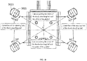
- FIG. 10 schematically shows the opening direction of the through hole of the ball portion 3020 of the shock-absorbing ball 302 of the pan-tilt 3 shown in FIG. 7 .
- the shock-absorbing balls 302 are evenly distributed on a circle centered on a center point O of the pan-tilt 3, such that the degree of shock absorbing of the pan-tilt 3 in all directions can be more even.
- the ball portion 3020 is provided with the first through hole 3021, a line connecting a center point O 1 of the first through hole and the center point O of the pan-tilt 3 is perpendicular to a centerline of the opening direction of the first through hole.
- the above-described arrangement of the position of the shock-absorbing balls and the opening direction of the through hole can obtain a better shock-absorbing effect.
- the opening direction of one of the two through holes can be set as the direction shown in FIG. 10
- the opening direction for another through hole for example, the second through hole 2023
- the plurality of shock-absorbing balls can be symmetrically arranged with respect to the center of the pan-tilt assembly 2 in the embodiments shown in FIGs. 2 to 6 , such that the shock-absorbing balls can balance and mitigate the vibration of body 1 caused by the motion of the pan-tilt 22 and the load 23.
- the plurality of shock-absorbing balls 202 can be evenly distributed on a circle centered on the center point of the pan-tilt assembly 2, such that the shock-absorbing balls can more evenly balance and mitigate the vibration of body 1 caused by the motion of the pan-tilt 22 and the load 23.
- the fixing member 204 in the embodiments shown in FIGs. 2 to 6 can be interchanged with the fixing member 304 in the embodiment shown in FIGs. 7 to 9 .
- the fixing members 204 and 304 can also have any other suitable structure as long as the shock-absorbing balls 202 and 302 can be fixed to the body 1, and the moving range of the moving member 200 can be limited in at least one direction.
- the limiting portions 2046 and 3046 and/or the connecting portions 2043 and 3043 can be fixed to the body 1 independently of the second connecting arms 2044 and 3044.
- the manner of connecting the first fixing portions 2022 and 3022 to the first connecting arms 2004 and 3004, and the manners of connecting the second fixing portions 2024 and 3024 to the second connecting arms 2044 and 3044 are not limited to the above embodiments, for example, elastic fixing members can be provided at the first connecting arms 2004 and 3004, the first fixing portions 2022 and 3022 can be elastic sheets or non-elastic sheets, and the first fixing portions 2022 and 3022 can be fixed to the first connecting arms 2004 and 3004 by connecting the elastic fixing members to the elastic sheets or the non-elastic sheets.
- engaging structures can be arranged at the first connecting arms 2004 and 3004 or the second connecting arms 2044 and 3044, and the first fixing portions 2022 and 3022 or the second fixing portions 2024 and 3024 can be engaged on the fixing members 204 and 304.
Landscapes
- Engineering & Computer Science (AREA)
- Aviation & Aerospace Engineering (AREA)
- Mechanical Engineering (AREA)
- Physics & Mathematics (AREA)
- General Engineering & Computer Science (AREA)
- Microelectronics & Electronic Packaging (AREA)
- Remote Sensing (AREA)
- General Physics & Mathematics (AREA)
- Acoustics & Sound (AREA)
- Signal Processing (AREA)
- Multimedia (AREA)
- Vibration Dampers (AREA)
- Accessories Of Cameras (AREA)
- Studio Devices (AREA)
- Vibration Prevention Devices (AREA)
Abstract
Description
- The present disclosure generally relates to a shock-absorbing structure and, more particularly, to a pan-tilt shock-absorbing structure, and a pan-tilt and unmanned vehicle using the same.
- In current designs of a pan-tilt, a shock-absorbing assembly of the pan-tilt carried by an aircraft is generally arranged outside a housing of the aircraft and is connected to a shock-absorbing ball under the aircraft via a connecting wire. The design manner separates the pan-tilt from the aircraft, causing the pan-tilt and the aircraft to be not integrated while occupying a relatively large space.
- Therefore, it is necessary to provide a pan-tilt shock-absorbing structure, and a pan-tilt assembly and an unmanned vehicle using the pan-tilt shock-absorbing structure, which can make the pan-tilt to be set within a body of the unmanned vehicle, such that the overall design of the unmanned vehicle can be harmonized as well as more integrated.
- A pan-tilt shock-absorbing structure is configured to connect a body to a pan-tilt load. The pan-tilt shock-absorbing structure includes a shock-absorbing ball and a positioning structure fixedly connecting the shock-absorbing ball to the body. The pan-tilt shock-absorbing structure is provided within the body. A pan-tilt shock-absorbing structure is configured to connect a body to a load of the pan-tilt. The pan-tilt shock-absorbing structure includes a shock-absorbing ball and a positioning structure fixedly connecting the shock-absorbing ball to the body, characterized in that, the pan-tilt shock-absorbing structure is provided within the body.
- Furthermore, the positioning structure includes a moving member and a fixing member. The fixing member is fixedly connected to an end of the shock-absorbing ball and the body, and the moving member is fixedly connected to another end of the shock-absorbing ball and the pan-tilt load.
- Furthermore, a first through hole is provided at the shock-absorbing ball and a center of the first through hole coincides with a center of the shock-absorbing ball.
- Furthermore, a line connecting the center of the first through hole and a center of the pan-tilt shock-absorbing structure is perpendicular to a centerline of an opening direction of the first through hole.
- Furthermore, a second through hole is provided at the shock-absorbing ball, a center of the second through hole coincides with the center of the shock-absorbing ball, and an opening direction of the second through hole is perpendicular to the opening direction of the first through hole.
- Furthermore, the number of the shock-absorbing ball is multiple and the multiple shock-absorbing balls are symmetrically distributed with respect to a center point of the pan-tilt shock-absorbing structure.
- Furthermore, the number of the shock-absorbing ball is multiple and the multiple shock-absorbing balls are evenly distributed on a circle centered on the center point of the pan-tilt shock-absorbing structure.
- Furthermore, the second through hole is provided at the shock-absorbing ball, the center of the second through hole coincides with the center of the shock-absorbing ball, and the opening direction of the second through hole is perpendicular to the opening direction of the first through hole.
- Furthermore, the number of the shock-absorbing ball is multiple and the multiple shock-absorbing balls are symmetrically distributed with respect to the center point of the pan-tilt shock-absorbing structure.
- Furthermore, the moving member includes a connecting plate and two first connecting arms extending from two opposite sides of the connecting plate. The connecting plate is fixedly connected to the load of the pan-tilt. Each first connecting arm includes two distal portions, and each distal portion is connected to the shock-absorbing ball.
- Furthermore, a first neck portion and a second neck portion are provided at the two distal portions, respectively. Each shock-absorbing ball is provided with a first elastic sleeve, and the first elastic sleeve is sleeved on the first neck portion or the second neck portion, respectively.
- Furthermore, the two first connecting arms are approximately parallel to the connecting plate.
- Furthermore, the connecting plate is fixedly connected to the pan-tilt load via a connecting structure.
- Furthermore, a fixing hole is arranged at the connecting plate, a locking hole is arranged at the connecting structure, and the connecting plate is locked to the connecting structure by a locking device passing through the fixing hole and the locking hole.
- Furthermore, the moving member is one-piece molded.
- Furthermore, the fixing member includes a positioning portion, two connecting portions extending from two opposite sides of the positioning portion, two second connecting arms, and a limiting portion, wherein the positioning portion is fixedly connected to the body, each second connecting arm extends from an end of the corresponding connecting portion that is distal from the positioning portion, each second connecting arm includes a distal end, each distal end is connected to a shock-absorbing ball, and the limiting portion is fixedly connected to the positioning portion and is approximately parallel to the positioning portion.
- Furthermore, a length of each second connecting arm is greater than a distance between inner sides of the two first connecting arms and is less than a distance between outer sides of the two first connecting arms.
- Furthermore, a third neck portion is provided at the distal end, each shock-absorbing ball is provided with a second elastic sleeve, and the second elastic sleeve is sleeved on the third neck portion.
- Furthermore, the fixing member is one-piece molded.
- Furthermore, the second connecting arm is approximately parallel to the positioning portion.
- Furthermore, a vertical distance between the limiting portion and the second connecting arm is greater than a diameter of the shock-absorbing ball.
- Furthermore, a positioning hole is provided at the positioning portion and a fixing device passes through the positioning hole to lock the positioning portion to an inner bottom wall of the body.
- Furthermore, the fixing member includes a positioning portion, two second connecting arms extending from two opposite sides of the positioning portion, a connecting portion, and a limiting portion extending from an end of the connecting portion distal from the positioning portion, wherein the positioning portion is fixedly connected to the body, each second connecting arm includes an distal end, and the distal end is connected to the shock-absorbing ball.
- Furthermore, a length of each second connecting arm is greater than a distance between inner sides of the two first connecting arms and is less than a distance between outer sides of the two first connecting arms.
- Furthermore, the connecting portion has a C-shape-like structure.
- Furthermore, a width of the connecting portion in a direction perpendicular to an extending direction of the connecting portion is smaller than the positioning portion.
- Furthermore, a length of the positioning portion in the direction perpendicular to the extending direction of the connecting portion is smaller than a width of the connecting portion in the extending direction of the connecting portion.
- Furthermore, the limiting portion is approximately parallel to the second connecting arm.
- Furthermore, the vertical distance between the limiting portion and the second connecting arm is greater than a diameter of the shock-absorbing ball.
- Furthermore, a third neck portion is provided at the distal end, each shock-absorbing ball is provided with a second elastic sleeve, and the second elastic sleeve is sleeved on the third neck portion.
- Furthermore, the fixing member is one-piece molded.
- Furthermore, a distance between the two distal portions of the first connecting arm gradually increases from the connecting plate in a direction away from the connecting plate.
- A pan-tilt assembly includes the pan-tilt shock-absorbing structure described above.
- An unmanned vehicle includes a body and a pan-tilt shock-absorbing structure arranged within the body. The pan-tilt shock-absorbing structure is the pan-tilt shock-absorbing structure described above.
-
-
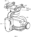
FIG. 1 is a perspective view of an unmanned vehicle according to an embodiment of the disclosure. -
FIG. 2 is a perspective view of a pan-tilt according to an embodiment of the disclosure. -
FIG. 3 is an exploded view of a pan-tilt according to an embodiment of the disclosure. -
FIG. 4 schematically shows assembling the pan-tilt inFIG. 3 to a body of an unmanned vehicle according an embodiment of the disclosure. -
FIG. 5 schematically shows the pan-tilt inFIG. 3 assembled to the body of the unmanned vehicle. -
FIG. 6 is a view ofFIG. 5 from another angle. -
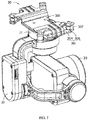
FIG. 7 is a perspective view of a pan-tilt according to another embodiment of the disclosure. -
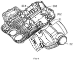
FIG. 8 is an exploded view of the pan-tilt inFIG. 7 . -
FIG. 9 schematically shows the pan-tilt inFIG. 7 assembled to a body of an unmanned vehicle. -
FIG. 10 schematically shows an opening direction of a through hole of a shock-absorbing ball of the pan-tilt inFIG. 7 . -
Unmanned vehicle 1000 Body 1 Assembly hole 10 Pan-tilt assembly 2, 3 Shock-absorbing structure 20, 30 Connecting structure 21, 31 Locking hole 210, 310 Pan-tilt 22, 32 Load 23, 33 Positioning structure 201, 301 Moving member 200, 300 Connecting plate 2000, 3000 Fixing hole 2001, 3001 Locking device 2002, 3002 First connecting arm 2004, 3004 First distal portion 2005, 3005 First neck portion 20050, 30050 Second distal portion 2006, 3006 Second neck portion 20060, 30060 Shock-absorbing ball 202, 302 Ball portion 2020, 3020 First through hole 2021, 3021 Second through hole 2023, 3023 First fixing portion 2022, 3022 Second fixing portion 2024, 3024 Fixing member 204, 304 Positioning portion 2040, 3040 Positioning hole 2041, 3041 Fixing device 2042, 3042 Connecting portion 2043, 3043 Second connecting arm 2044, 3044 Distal end 20440, 30440 Third neck portion 20442, 30442 Limiting portion 2046, 3046 - The disclosure will be further illustrated by the following embodiments with reference to the above drawings.
- Technical schemes of the disclosed embodiments will be clearly and completely described below with reference to the drawings. It will be appreciated that the described embodiments are some rather than all of the embodiments of the present disclosure. Other embodiments conceived by those having ordinary skills in the art on the basis of the disclosed embodiments without inventive efforts should fall within the scope of the present disclosure.
- As used herein, when a first component is referred to as "fixed to" a second component, it is intended that the first component may be directly attached to the second component or may be indirectly attached to the second component via another component. When a first component is referred to as "connecting" to a second component, it is intended that the first component may be directly connected to the second component or may be indirectly connected to the second component via a third component between them. The terms "perpendicular," "horizontal," "left," "right," and similar expressions used herein are merely intended for description.
- Unless otherwise defined, all the technical and scientific terms used herein have the same or similar meanings as generally understood by one of ordinary skill in the art. As described herein, the terms used in the specification of the present disclosure are intended to describe exemplary embodiments, instead of limiting the present disclosure. The term "and/or" used herein includes any suitable combination of one or more related items listed.
- As shown in
FIG. 1 , an embodiment of the present disclosure provides anunmanned vehicle 1000. Theunmanned vehicle 1000 can be an unmanned aerial vehicle (UAV), for example, a rotary-wing UAV, a fixed-wing UAV, or a UAV having both fixed-wing and rotary-wing. The rotary-wing can be a single-rotor, dual-rotor, tri-rotor, quad-rotor, hexa-rotor, octa-rotor, or the like. It can be understood that, in some embodiments, the unmanned vehicle can be an unmanned vehicle in the water (e.g., a driverless boat or an unmanned submarine), an unmanned vehicle on the ground (e.g., a driverless car), an unmanned vehicle in air (e.g., the UAV), or the like. In the present embodiment, theunmanned vehicle 1000 is the rotary-wing unmanned aerial vehicle (UAV). Theunmanned vehicle 1000 includes a body 1 and apan-tilt assembly 2 mounted on the body 1. - As shown in
FIG. 2 , thepan-tilt assembly 2 includes a shock-absorbingstructure 20, a connectingstructure 21, a pan-tilt 22, and aload 23. The shock-absorbingstructure 20 is arranged within the body 1. The connectingstructure 21 connects the shock-absorbingstructure 20 and the pan-tilt 22. The pan-tilt 22 carries theload 23 thereon. The pan-tilt 22 can be a single-axis pan-tilt, a dual-axis pan-tilt, or a triple-axis pan-tilt. The connectingstructure 21, the pan-tilt 22, and theload 23 are arranged outside the body 1. Theload 23 can be any sensing apparatus or photographing apparatus that is suitable for being mounted on the pan-tilt. In the present embodiment, theload 23 is a photographing apparatus, such as a camera. In the present embodiment, a center point of the shock-absorbingstructure 20 of the pan-tilt coincides with a center point of thepan-tilt assembly 2. - Referring also to
FIG. 3 , the shock-absorbingstructure 20 includes a plurality of shock-absorbingballs 202 and apositioning structure 201 fixedly connecting the plurality of shock-absorbingballs 202 to the body 1. Thepositioning structure 201 includes a movingmember 200 and two fixingmembers 204 for fixing thepan-tilt assembly 2 within the body 1. The two fixingmembers 204 are fixedly arranged within the body 1. The shock-absorbingballs 202 connects to the movingmember 200 and the fixingmember 204. The movingmember 200 is fixedly connected to the connectingstructure 21, and the movingmember 200 can move relative to the fixingmember 204 to drive the pan-tilt 22 and theload 23 together to move relative to the body 1. - The moving
member 200 includes a connectingplate 2000 and two first connectingarms 2004 respectively arranged at opposite sides of the connectingplate 2000. Each first connectingarm 2004 is connected to the connectingplate 2000 through an extendingportion 2003. The two first connectingarms 2004, the two extendingportions 2003, and the connectingplate 2000 can be one-piece molded. It can be appreciated that components of the movingmember 200 can be, not one-piece molded, but fixed together using various fixing methods known by those skilled in the art, such as screwing, snap-fastening, or the like. In the present embodiment, a plurality of fixingholes 2001 are arranged at the connectingplate 2000, and a plurality of corresponding lockingholes 210 are arranged at the connectingstructure 21. Thelocking device 2002 passes through the plurality of fixingholes 2001 and the corresponding locking holes 210, such that the connectingplate 2000 can be fixedly connected to the connectingstructure 21. It can be understood that, in some other embodiments, a fixing manner of the connectingplate 2000 and the connectingstructure 21 is not limited to the fixing manner in the present embodiment, and can be, e.g., a snap fit, an interference fit, or the like, as long as the connectingplate 2000 can be fixedly connected to the connectingstructure 21 and cannot move relative to the connectingstructure 21. - Two extending
portions 2003 are respectively formed by extending upward from two opposite sides of the connectingplate 2000. Each first connectingarm 2004 is respectively formed by extending from an end of the extendingportion 2003 distal from the connectingplate 2000 in a direction away from the connectingplate 2000. Two ends of each first connectingarm 2004 are respectively connected to the shock-absorbingball 202. Each first connectingarm 2004 is approximately parallel to the connectingplate 2000. The two ends of each first connectingarm 2004 include a firstdistal portion 2005 and a seconddistal portion 2006, respectively. Each firstdistal portion 2005 or seconddistal portion 2006 is connected to a shock-absorbingball 202. Each first connectingarm 2004 includes afirst neck portion 20050 formed near the firstdistal portion 2005. Eachfirst neck portion 20050 includes two notches formed correspondingly at two sides of the firstdistal portion 2005. That is, a size of thefirst neck portion 20050 in a direction perpendicular to thefirst neck portion 20050 is smaller than a size of the firstdistal portion 2005. Each first connectingarm 2004 includes asecond neck portion 20060 formed near the seconddistal portion 2006. Eachsecond neck portion 20060 includes two notches formed correspondingly at two sides of the seconddistal portion 2006. That is, a size of thesecond neck portion 20060 in a direction perpendicular to thesecond neck portion 20060 is smaller than a size of the seconddistal portion 2006. - Each fixing
member 204 includes apositioning portion 2040, two connectingportions 2043, two second connectingarms 2044, and a limitingportion 2046. Thepositioning portion 2040 is configured to fixedly connect to an inside of the body 1, such that the fixingmember 204 can be fixedly arranged at an inner bottom wall of the body 1. The connectingportion 2043 is configured to connect thepositioning portion 2040 to the second connectingarm 2044. The components of the fixingmember 204, such as thepositioning portion 2040, the two connectingportions 2043, the two second connectingarms 2044, and the limitingportion 2046, can be one-piece molded. It can be appreciated that the components of the fixing device can also be separately arranged and fixed together by various fixing methods know by those skilled in the art, such as screwing, snap-fastening, or the like. - The
positioning portion 2040 is provided with a plurality of positioning holes 2041. A plurality of fixingdevices 2042 pass through the plurality ofpositioning holes 2041 to lock on the inner bottom wall of the body 1. It can be understood that, in some embodiments, thepositioning portion 2040 can also be fixedly connected to the inner bottom wall of the body by other manners, such as a snap fit, an interference fit, or the like, as long as thepositioning portion 2040 can be fixedly connected to the inner bottom wall of the body and cannot move relative to the inner bottom wall of the body. - Each connecting
portion 2043 is formed by extending from an end of thepositioning portion 2040 toward a direction away from thepositioning portion 2040. Each second connectingarm 2044 is formed by extending from an end of the corresponding connectingportion 2043 distal from thepositioning portion 2040 in a direction away from thepositioning portion 2040 and approximately parallel to thepositioning portion 2040. Each second connectingarm 2044 includes adistal end 20440 for connecting to a shock-absorbingball 202. The second connectingarm 2044 includes athird neck portion 20442 formed near thedistal end 20440. Eachthird neck portion 20442 includes two notches formed correspondingly at two sides of the second connectingarm 2044. That is, a size of thethird neck portion 20442 in a direction perpendicular to thethird neck portion 20442 is smaller than a size of thedistal end 20440. The limitingportion 2046 is formed by extending from a side of thepositioning portion 2040 where the connectingportion 2043 is not arranged, and the limitingportion 2046 is approximately parallel to thepositioning portion 2040 and slightly higher than thepositioning portion 2040. A vertical height difference between the limitingportion 2046 and the second connectingarm 2044 is greater than a diameter of the shock-absorbingball 202, such that the movingmember 200 can move up and down in a space defined by the limitingportion 2046 and thepositioning portion 2040. - The shock-absorbing
ball 202 includes aball portion 2020, afirst fixing portion 2022, and asecond fixing portion 2024. Theball portion 2020 is provided with a first throughhole 2021 and a second throughhole 2023. An opening direction of the first throughhole 2021 is approximately perpendicular to an opening direction of the second throughhole 2023, and a center point of the first throughhole 2021 and a center point of the second throughhole 2023 coincide with the center point of the shock-absorbingball 202. Opening a plurality of through holes in theball portion 2020 can achieve a better shock absorbing effect. Theball portion 2020 is made of an elastic material. Thefirst fixing portion 2022 is configured to connect to the firstdistal portion 2005 or the seconddistal portion 2006 of the first connectingarm 2004 of the movingmember 200. Thesecond fixing portion 2024 is configured to connect to the fixingmember 204. Thefirst fixing portion 2022 is a sleeve made of an elastic material and can be sleeved on the firstdistal portion 2005 or the seconddistal portion 2006 to fixedly connect the shock-absorbingball 202 to the movingmember 200. Thesecond fixing portion 2024 is similar to thefirst fixing portion 2022 and is also a sleeve made of an elastic material and can be sleeved on thedistal end 20440 to fixedly connect the shock-absorbingball 202 to the fixingmember 204. The sleeve direction of thefirst fixing portion 2022 is approximately perpendicular to the sleeve direction of thesecond fixing portion 2024. In some other embodiments, the sleeve direction of thefirst fixing portion 2022 and the sleeve direction of thesecond fixing portion 2024 is not limited to be perpendicular to each other, and may be, for example, parallel to each other or in another positional relationship. The sleeve directions need to be set in accordance with the extending directions of the firstdistal portion 2005, the seconddistal portion 2006, and thedistal end 20440. It should be appreciated that thefirst fixing portion 2022 and thesecond fixing portion 2024 are provided in the sleeve shape for illustration and ease of installation. The elastic material is intended for further absorbing the shock. In some other embodiments, thefirst fixing portion 2022 and thesecond fixing portion 2024 can be made of another material and have another structure, as long as the shock-absorbingball 202 can be fixedly connected to the movingmember 200 and the fixingmember 204. For example, the shock-absorbingball 202 can be fixedly connected to the movingmember 200 and the fixingmember 204 by a snap fit or the like. - Referring also to
FIG. 4 , when thepan-tilt assembly 2 is being assembled to the body 1 of theunmanned vehicle 1000, thefirst fixing portion 2022 and thesecond fixing portion 2024 of the shock-absorbingball 202 are respectively sleeved on thefirst neck portion 20050 and thesecond neck portion 20060 of the first connectingarm 2004 of the movingmember 200 and thethird neck portion 20442 of the second connectingarm 2044 of the fixingmember 204, such that the shock-absorbingball 202 can be fixedly connected between the movingmember 200 and the fixingmember 204. The fixingmember 204 is fixedly connected to the inner bottom wall of the body 1 using thefixing device 2042. The connectingstructure 21 is fixedly connected to the connectingplate 2000 through a mountinghole 10 provided at the body 1, such that thepan-tilt assembly 2 can be assembled on the body 1. - After the assembly is completed, as shown in
FIGs. 5 and6 , the movingmember 200 and the fixingmember 204 are connected by the shock-absorbingball 202. Since the shock-absorbingball 202 is made of an elastic material, and the shock-absorbingball 202 is provided with the first throughhole 2021 and the second throughhole 2023, such that the movingmember 200 can move relative to the fixingmember 204 and can return to an initial position under the elastic force of the shock-absorbingball 202. A distance between the two limitingportions 2046 is greater than a distance between inner sides of the two first connecting arms 2004 (i.e., a side of the first connectingarm 2004 close to the connecting plate 2000) and is less than a distance between outer sides of the two first connecting arms 2004 (i.e., a side of the first connectingarm 2004 distal from the connecting plate 2000). Therefore, the two limitingportions 2046 of the fixingmember 204 can limit a moving range of the movingmember 200 in a direction perpendicular to the bottom wall of the body to prevent the moving range of the movingmember 200 from being too large to affect other members assembled in the body, and to prevent a tension on the shock-absorbingball 202 from being too large to damage the elasticity of the shock-absorbingball 202. During the movement of theunmanned vehicle 1000, if the pan-tilt 22 and theload 23 thereon move relative to the body 1, a vibration generated by the movement is transmitted to the fixingmember 204 and the body 1 connected to the fixingmember 204 via the shock-absorbingball 202. Due to the shock absorbing effect of the shock-absorbingball 202, the influence of the vibration on the body 1 can be greatly reduced. - As shown in
FIG. 7 , a perspective view of a pan-tilt assembly 3 is provided according to another embodiment of the present disclosure. The pan-tilt assembly 3 includes a shock-absorbingstructure 30, a connectingstructure 31, a pan-tilt 32, and aload 33. The shock-absorbingstructure 30 is arranged within the body 1. The connectingstructure 31 connects the shock-absorbingstructure 30 and the pan-tilt 32. Theload 33 is provided at the pan-tilt 32. The pan-tilt 32 can be a single-axis pan-tilt, a dual-axis pan-tilt, or a triple-axis pan-tilt. The connectingstructure 31, the pan-tilt 32, and theload 33 are arranged outside the body 1. Theload 33 can be any sensing apparatus or photographing apparatus that is suitable for being mounted on the pan-tilt. In the present embodiment, theload 33 is a photographing apparatus, such as a camera. In the present embodiment, a center point of the shock-absorbingstructure 20 of the pan-tilt coincides with a center point of thepan-tilt assembly 2. - Referring also to
FIG. 8 , the shock-absorbingstructure 30 includes a shock-absorbingball 302 and a positioning structure 301 fixedly connecting the shock-absorbingball 302 to the body 1. The positioning structure 301 includes a movingmember 300 and a fixingmember 304. The movingmember 300 is fixedly connected to the connectingstructure 31, and the movingmember 300 can move relative to the fixingmember 304 to drive theload 32 to move relative to the body 1. - The moving
member 300 is similar to the movingmember 200 and includes a connectingplate 3000 and two first connectingarms 3004 respectively arranged at opposite sides of the connectingplate 3000. Each first connectingarm 3004 is connected to the connectingplate 3000 through an extendingportion 3003. The two first connectingarms 3004 and the connectingplate 3000 can be one-piece molded. The first connectingarm 3004 is approximately parallel to the connectingplate 2000. Each first connectingarm 3004 includes a firstdistal portion 3005 and a seconddistal portion 3006, respectively. Each firstdistal portion 3005 or seconddistal portion 3006 is connected to a shock-absorbingball 302. A distance between the firstdistal portion 3005 and the seconddistal portion 3006 of the first connectingarm 3004 gradually increases from the connectingplate 3000 in the direction away from the connectingplate 3000. In the present embodiment, the two firstdistal portions 3005 and the two seconddistal portions 3006 are symmetrically arranged with respect to a center of the movingmember 300, such that the plurality of shock-absorbing balls connected to the two firstdistal portions 3005 and the two seconddistal portions 3006 can be symmetrically arranged with respect to a center of the pan-tilt assembly 3 to balance and mitigate the vibration of the body 1 caused by the motion of the pan-tilt 32 and theload 33. Further, in some embodiments, the two firstdistal portions 3005 and the two seconddistal portions 3006 can be evenly distributed on a circle centered on the center of the movingmember 300, such that the plurality of shock-absorbing balls can be evenly distributed on a circle centered on the center of the pan-tilt assembly 3 to balance and mitigate the shock of the body 1 caused by the motion of the pan-tilt 32 and theload 33. - The connecting
plate 3000 is fixedly connected to the connectingstructure 31. In the present embodiment, a plurality of fixingholes 3001 are arranged at the connectingplate 3000, and a plurality of corresponding lockingholes 210 are arranged at the connectingstructure 31. A plurality of lockingdevices 3002 pass through the plurality of fixingholes 3001 and the corresponding locking holes 310, such that the connectingplate 3000 can be fixedly connected to the connectingstructure 31. It can be understood that, in some other embodiments, a fixing manner of the connectingplate 3000 and the connectingstructure 31 is not limited to the fixing manner in the present embodiment, and can be, e.g., a snap fit, an interference fit, or the like, as long as the connectingplate 3000 can be fixedly connected to the connectingstructure 31 and cannot move relative to the connectingstructure 31. - Two extending
portions 3003 are respectively formed by extending upward from two opposite sides of the connectingplate 3000. The first connectingarm 3004 is formed by extending from an end of the extendingportion 3003 distal from the connectingplate 3000 in a direction away from the connectingplate 3000. The first connectingarm 3004 is approximately parallel to the connectingplate 3000. Each first connectingarm 3004 includes a first neck portion 30050 formed near the firstdistal portion 3005. The first neck portion 30050 includes two notches formed correspondingly at two sides of the firstdistal portion 3005. That is, a size of the first neck portion 30050 in a direction perpendicular to the first neck portion 30050 is smaller than a size of the firstdistal portion 3005. Each first connectingarm 3004 includes asecond neck portion 30060 formed near the seconddistal portion 3006. Thefirst neck portion 20050 includes two notches formed at two sides corresponding to the firstdistal portion 2005. That is, thesecond neck portion 30060 includes two notches formed at two sides corresponding to the seconddistal portion 3006. That is, a size of thesecond neck portion 30060 in a direction perpendicular to thesecond neck portion 30060 is smaller than a size of the seconddistal portion 3006. - The fixing
member 304 includes apositioning portion 3040, connectingportions 3043, two second connectingarms 3044, and a limitingportion 3046. The components of the fixingdevice 304, such as thepositioning portion 3040, the two connectingportions 3043, the two second connectingarms 3044, and the limitingportion 3046, can be one-piece molded. It can be appreciated that the components of the fixing device can also be separately arranged and fixed together by various fixing methods known to those skilled in the art, such as screwing, snap-fastening, or the like. - The
positioning portion 3040 is configured to fixedly connect to an inside of the body 1, such that the fixingmember 304 can be fixedly arranged at an inner bottom wall of the body 1. Thepositioning portion 3040 is provided with a plurality of positioning holes 3041. A plurality of fixingdevices 3042 pass through the plurality ofpositioning holes 3041 to lock on the inner bottom wall of the body 1. It can be understood that, in some embodiments, thepositioning portion 3040 can also be fixedly connected to the inner bottom wall of the body by another manner, such as a snap fit, an interference fit, or the like, as long as thepositioning portion 3040 can be fixedly connected to the inner bottom wall of the body and cannot move relative to the inner bottom wall of the body. - The connecting
portion 3043 is formed by extending from an end of thepositioning portion 3040 toward a direction away from thepositioning portion 3040. The connectingportion 3043 has a C-shape-like structure for connecting thepositioning portion 3040 and the limitingportion 3046. A width of the connectingportion 3043 in a radial direction of thepositioning portion 3040 is smaller than a width of thepositioning portion 3040, thereby facilitating the installation of thefixing devices 3042. - Each second connecting
arm 3044 is formed by extending from an end of thepositioning portion 3040 distal from thepositioning portion 3040 in a direction away from thepositioning portion 2040 and approximately parallel to thepositioning portion 3040. The second connectingarm 3044 is slightly lower than thepositioning portion 3040. Corresponding to the firstdistal portion 3005 and the seconddistal portion 3006 of the first connectingarm 3004, a distance between the two second connectingarms 3044 gradually increases from thepositioning portion 3040 in the direction away from thepositioning portion 3040. Each second connectingarm 3044 includes adistal end 30440 for connecting to a shock-absorbingball 302. The second connectingarm 3044 includes athird neck portion 30442 formed near thedistal end 30440. Eachthird neck portion 30442 includes two notches formed correspondingly at two sides of thedistal end 30440. That is, a size of thethird neck portion 30442 in a direction perpendicular to thethird neck portion 30442 is smaller than a size of thedistal end 30440. - The limiting
portion 3046 is formed by extending from a side of the connectingportion 3043 distal from theposition portion 3040 in a direction parallel to the second connectingarm 3044. A length of the limitingportion 3046 in a radial direction is greater than a width of the connectingportion 3043 in the radial direction, and the length of the limitingportion 3046 in the radial direction is greater than a distance between the two first connectingarms 3004, such that a moving range of the movingmember 200 in a direction perpendicular to thepositioning portion 3040 can be limited. A vertical distance between the limitingportion 3046 and the second connectingarm 3044 is greater than a diameter of the shock-absorbingball 302. - The shock-absorbing
ball 302 includes aball portion 3020, afirst fixing portion 3022, and asecond fixing portion 3024. Theball portion 3020 is provided with a first throughhole 3021. A center point of the first throughhole 3021 coincides with the center point of the shock-absorbingball 302. Theball portion 3020 is made of an elastic material. Thefirst fixing portion 3022 is configured to connect to the firstdistal portion 3005 or the seconddistal portion 3006 of the first connectingarm 3004 of the movingmember 300. Thesecond fixing portion 3024 is configured to connect to the fixingmember 304. Thefirst fixing portion 3022 is a sleeve made of an elastic material and can be sleeved on the first neck portion 30050 or thesecond neck portion 30060 to fixedly connect the shock-absorbingball 302 to the movingmember 300. Thesecond fixing portion 3024 is similar to thefirst fixing portion 3022 and is also a sleeve made of an elastic material and can be sleeved on thethird neck portion 30442 to fixedly connect the shock-absorbingball 202 to the fixingmember 204. The sleeve direction of thefirst fixing portion 3022 is approximately perpendicular to the sleeve direction of thesecond fixing portion 3024. In some other embodiments, the sleeve direction of thefirst fixing portion 3022 and the sleeve direction of thesecond fixing portion 3024 is not limited to be perpendicular to each other, and may be, for example, parallel to each other or in another positional relationship. The sleeve directions need to be set in accordance with the extending direction of the firstdistal portion 3005, the seconddistal portion 3006, and thedistal end 30440. It should be appreciated that thefirst fixing portion 3022 and thesecond fixing portion 3024 are provided in the sleeve shape for illustration and ease of installation. The elastic material is intended for further absorbing the shock. In some other embodiments, thefirst fixing portion 3022 and thesecond fixing portion 3024 can be made of another material and have another structure, as long as the shock-absorbingball 302 can be fixedly connected to the movingmember 300 and the fixingmember 304. For example, the shock-absorbingball 302 can be fixedly connected to the movingmember 300 and the fixingmember 304 by a snap fit or the like. - Referring also to
FIG. 8 , when the pan-tilt 3 is being assembled to the body 1 of theunmanned vehicle 1000, thefirst fixing portion 3022 and thesecond fixing portion 3024 of the shock-absorbingball 302 are respectively sleeved on the first neck portion 30050 and thesecond neck portion 30060 of the first connectingarm 3004 of the movingmember 300 and thethird neck portion 30442 of the second connectingarm 3044 of the fixingmember 304, such that the shock-absorbingball 302 can be fixedly connected between the movingmember 300 and the fixingmember 304. The fixingmember 304 is fixedly connected to the inner bottom wall of the body 1 using thefixing device 3042. The connectingstructure 31 is fixedly connected to the connectingplate 3000 through a mountinghole 10 provided at the body 1, such that the pan-tilt 3 can be assembled on the body 1. - After the assembly is completed, as shown in
FIG. 9 , the movingmember 300 and the fixingmember 304 are connected by the shock-absorbingball 302. Since the shock-absorbingball 302 is made of an elastic material, and the shock-absorbingball 302 is provided with the first throughhole 3021, the movingmember 300 can move relative to the fixingmember 304. A distance between the two limitingportions 3046 is greater than a distance between inner sides of the two first connecting arms 3004 (i.e., a side of the first connectingarm 2004 close to the connecting plate 2000) and is less than a distance between outer sides of the two first connecting arms 3004 (i.e., a side of the first connectingarm 2004 distal from the connecting plate 2000). Therefore, the two limitingportions 3046 of the fixingmember 304 can limit a moving range of the movingmember 300 in a direction perpendicular to the bottom wall of the body to prevent the moving range of the movingmember 300 from being too large to affect other members assembled in the body, and to prevent a tension on the shock-absorbingball 302 from being too large to damage the elasticity of the shock-absorbingball 202. -
FIG. 10 schematically shows the opening direction of the through hole of theball portion 3020 of the shock-absorbingball 302 of the pan-tilt 3 shown inFIG. 7 . The shock-absorbingballs 302 are evenly distributed on a circle centered on a center point O of the pan-tilt 3, such that the degree of shock absorbing of the pan-tilt 3 in all directions can be more even. In order to achieve a better shock-absorbing effect, theball portion 3020 is provided with the first throughhole 3021, a line connecting a center point O1 of the first through hole and the center point O of the pan-tilt 3 is perpendicular to a centerline of the opening direction of the first through hole. The above-described arrangement of the position of the shock-absorbing balls and the opening direction of the through hole can obtain a better shock-absorbing effect. - It can be understood that when two through holes are provided in embodiments shown in
FIGs. 2 to 6 , the opening direction of one of the two through holes, for example, the first throughhole 2021, can be set as the direction shown inFIG. 10 , and the opening direction for another through hole, for example, the second throughhole 2023, can be set to be perpendicular to the opening direction of the first throughhole 2021, such that a better shock-absorbing effect of the shock-absorbingball 202 can be achieved. - It can be understood that the plurality of shock-absorbing balls can be symmetrically arranged with respect to the center of the
pan-tilt assembly 2 in the embodiments shown inFIGs. 2 to 6 , such that the shock-absorbing balls can balance and mitigate the vibration of body 1 caused by the motion of the pan-tilt 22 and theload 23. In some embodiments, the plurality of shock-absorbingballs 202 can be evenly distributed on a circle centered on the center point of thepan-tilt assembly 2, such that the shock-absorbing balls can more evenly balance and mitigate the vibration of body 1 caused by the motion of the pan-tilt 22 and theload 23. - It can be understood that the fixing
member 204 in the embodiments shown inFIGs. 2 to 6 can be interchanged with the fixingmember 304 in the embodiment shown inFIGs. 7 to 9 . In some other embodiments, the fixingmembers balls member 200 can be limited in at least one direction. It can be appreciated that the limitingportions portions arms - It can be understood that the manner of connecting the
first fixing portions arms second fixing portions arms arms first fixing portions first fixing portions arms arms arms first fixing portions second fixing portions members - Various changes and modifications can be made by those skilled in the art on the basis of the technique concept of the present disclosure, which should fall within the scope of the present disclosure.
Claims (96)
- A pan-tilt shock-absorbing structure, configured to connect a body to a pan-tilt load, the pan-tilt shock-absorbing structure including a shock-absorbing ball and a positioning structure fixedly connecting the shock-absorbing ball to the body, characterized in that, the pan-tilt shock-absorbing structure is provided within the body.
- The pan-tilt shock-absorbing structure according to claim 1, characterized in that the positioning structure includes a moving member and a fixing member, the fixing member is fixedly connected to an end of the shock-absorbing ball and the body, and the moving member is fixedly connected to another end of the shock-absorbing ball and the pan-tilt load.
- The pan-tilt shock-absorbing structure according to claim 2, characterized in that a first through hole is provided at the shock-absorbing ball and a center of the first through hole coincides with a center of the shock-absorbing ball.
- The pan-tilt shock-absorbing structure according to claim 3, characterized in that, a line connecting the center of the first through hole and a center of the pan-tilt shock-absorbing structure is perpendicular to a centerline of an opening direction of the first through hole.
- The pan-tilt shock-absorbing structure according to claim 4, characterized in that, a second through hole is provided at the shock-absorbing ball, a center of the second through hole coincides with the center of the shock-absorbing ball, and an opening direction of the second through hole is perpendicular to the opening direction of the first through hole.
- The pan-tilt shock-absorbing structure according to claim 3, characterized in that, the number of the shock-absorbing ball is multiple and the multiple shock-absorbing balls are symmetrically distributed with respect to a center point of the pan-tilt shock-absorbing structure.
- The pan-tilt shock-absorbing structure according to claim 3, characterized in that, the number of the shock-absorbing ball is multiple and the multiple shock-absorbing balls are evenly distributed on a circle centered on the center point of the pan-tilt shock-absorbing structure.
- The pan-tilt shock-absorbing structure according to claim 3, characterized in that, a second through hole is provided at the shock-absorbing ball, a center of the second through hole coincides with the center of the shock-absorbing ball, and an opening direction of the second through hole is perpendicular to the opening direction of the first through hole.
- The pan-tilt shock-absorbing structure according to claim 8, characterized in that, the number of the shock-absorbing ball is multiple and the multiple shock-absorbing balls are symmetrically distributed with respect to a center point of the pan-tilt shock-absorbing structure.
- The pan-tilt shock-absorbing structure according to any one of claims 2 to 9, characterized in that, the moving member includes a connecting plate and two first connecting arms extending from two opposite sides of the connecting plate, the connecting plate is fixedly connected to the load of the pan-tilt, each first connecting arm includes two distal portions, and each distal portion is connected to the shock-absorbing ball.
- The pan-tilt shock-absorbing structure according to claim 10, characterized in that, a first neck portion and a second neck portion are provided at the two distal portions, respectively, each shock-absorbing ball is provided with a first elastic sleeve, and the first elastic sleeve is sleeved on the first neck portion or the second neck portion, respectively.
- The pan-tilt shock-absorbing structure according to claim 11, characterized in that, the two first connecting arms are approximately parallel to the connecting plate.
- The pan-tilt shock-absorbing structure according to claim 10, characterized in that, the connecting plate is fixedly connected to the pan-tilt load via a connecting structure.
- The pan-tilt shock-absorbing structure according to claim 13, characterized in that, a fixing hole is arranged at the connecting plate, a locking hole is arranged at the connecting structure, and the connecting plate is locked to the connecting structure by a locking device passing through the fixing hole and the locking hole.
- The pan-tilt shock-absorbing structure according to claim 10, characterized in that, the moving member is one-piece molded.
- The pan-tilt shock-absorbing structure according to claim 10, characterized in that, the fixing member includes a positioning portion, two connecting portions extending from two opposite sides of the positioning portion, two second connecting arms, and a limiting portion, wherein the positioning portion is fixedly connected to the body, each second connecting arm extends from an end of the corresponding connecting portion that is distal from the positioning portion, each second connecting arm includes a distal end, each distal end is connected to a shock-absorbing ball, and the limiting portion is fixedly connected to the positioning portion and is approximately parallel to the positioning portion.
- The pan-tilt shock-absorbing structure according to claim 16, characterized in that, a length of each second connecting arm is greater than a distance between inner sides of the two first connecting arms and is less than a distance between outer sides of the two first connecting arms.
- The pan-tilt shock-absorbing structure according to claim 16, characterized in that, a third neck portion is provided at the distal end, each shock-absorbing ball is provided with a second elastic sleeve, and the second elastic sleeve is sleeved on the third neck portion.
- The pan-tilt shock-absorbing structure according to claim 16, characterized in that, the fixing member is one-piece molded.
- The pan-tilt shock-absorbing structure according to claim 16, characterized in that, the second connecting arm is approximately parallel to the positioning portion.
- The pan-tilt shock-absorbing structure according to claim 16, characterized in that, a vertical distance between the limiting portion and the second connecting arm is greater than a diameter of the shock-absorbing ball.
- The pan-tilt shock-absorbing structure according to claim 16, characterized in that, a positioning hole is provided at the positioning portion and a fixing device passes through the positioning hole to lock the positioning portion to an inner bottom wall of the body.
- The pan-tilt shock-absorbing structure according to claim 10, characterized in that, the fixing member includes a positioning portion, two second connecting arms extending from two opposite sides of the positioning portion, a connecting portion, and a limiting portion extending from an end of the connecting portion distal from the positioning portion, wherein the positioning portion is fixedly connected to the body, each second connecting arm includes an distal end, and the distal end is connected to the shock-absorbing ball.
- The pan-tilt shock-absorbing structure according to claim 23, characterized in that, a length of each second connecting arm is greater than a distance between inner sides of the two first connecting arms and is less than a distance between outer sides of the two first connecting arms.
- The pan-tilt shock-absorbing structure according to claim 23, characterized in that, the connecting portion has a C-shape-like structure.
- The pan-tilt shock-absorbing structure according to claim 25, characterized in that, a width of the connecting portion in a direction perpendicular to an extending direction of the connecting portion is smaller than the positioning portion.
- The pan-tilt shock-absorbing structure according to claim 26, characterized in that, a length of the positioning portion in the direction perpendicular to the extending direction of the connecting portion is smaller than a width of the connecting portion in the extending direction of the connecting portion.
- The pan-tilt shock-absorbing structure according to claim 23, characterized in that, the limiting portion is approximately parallel to the second connecting arm.
- The pan-tilt shock-absorbing structure according to claim 23, characterized in that, a vertical distance between the limiting portion and the second connecting arm is greater than a diameter of the shock-absorbing ball.
- The pan-tilt shock-absorbing structure according to claim 23, characterized in that, a third neck portion is provided at the distal end, each shock-absorbing ball is provided with a second elastic sleeve, and the second elastic sleeve is sleeved on the third neck portion.
- The pan-tilt shock-absorbing structure according to claim 23, characterized in that, the fixing member is one-piece molded.
- The pan-tilt shock-absorbing structure according to claim 10, characterized in that, a distance between the two distal portions of the first connecting arm gradually increases from the connecting plate in a direction away from the connecting plate.
- A pan-tilt assembly for an unmanned vehicle, the unmanned vehicle including a body, characterized in that, the pan-tilt assembly includes a shock-absorbing structure, a connecting structure, and a load, the shock-absorbing structure is arranged within the body, the load is fixedly connected to the shock-absorbing structure via the connecting structure, and the connecting structure and the load are arranged outside the body.
- The pan-tilt assembly according to claim 33, characterized in that, the pan-tilt shock-absorbing structure includes a shock-absorbing ball and a positioning structure fixedly connecting the shock-absorbing ball to the body, the positioning structure includes a moving member and a fixing member, the fixing member is fixedly connected to an end of shock-absorbing ball and the body, and the moving member is fixedly connected to another end of shock-absorbing ball and the load of the pan-tilt.
- The pan-tilt assembly according to claim 34, characterized in that, a first through hole is provided at the shock-absorbing ball and a center of the first through hole coincides with a center of the shock-absorbing ball.
- The pan-tilt assembly according to claim 35, characterized in that, a line connecting the center of the first through hole and a center of the pan-tilt shock-absorbing structure is perpendicular to a centerline of an opening direction of the first through hole.
- The pan-tilt assembly according to claim 36, characterized in that, a second through hole is provided at the shock-absorbing ball, a center of the second through hole coincides with the center of the shock-absorbing ball, and an opening direction of the second through hole is perpendicular to the opening direction of the first through hole.
- The pan-tilt assembly according to claim 35, characterized in that the number of the shock-absorbing ball is multiple and the multiple shock-absorbing balls are symmetrically distributed with respect to a center point of the pan-tilt shock-absorbing structure.
- The pan-tilt assembly according to claim 35, characterized in that, the number of the shock-absorbing ball is multiple and the multiple shock-absorbing balls are evenly distributed on a circle centered on the center point of the pan-tilt shock-absorbing structure.
- The pan-tilt assembly according to claim 35, characterized in that a second through hole is provided at the shock-absorbing ball, a center of the second through hole coincides with the center of the shock-absorbing ball, and an opening direction of the second through hole is perpendicular to the opening direction of the first through hole.
- The pan-tilt assembly according to claim 40, characterized in that, the number of the shock-absorbing ball is multiple and the multiple shock-absorbing balls are symmetrically distributed with respect to a center point of the pan-tilt shock-absorbing structure.
- The pan-tilt assembly according to any one of claims 34 to 41, characterized in that, the moving member includes a connecting plate and two first connecting arms extending from two opposite sides of the connecting plate, the connecting plate is fixedly connected to the load of the pan-tilt, each first connecting arm includes two distal portions, and each distal portion is connected to a shock-absorbing ball.
- The pan-tilt assembly according to claim 42, characterized in that, a first neck portion and a second neck portion are provided at the two distal portions, respectively, each shock-absorbing ball is provided with a first elastic sleeve, and the first elastic sleeve is sleeved on the first neck portion or the second neck portion, respectively.
- The pan-tilt assembly according to claim 42, characterized in that, the two first connecting arms are approximately parallel to the connecting plate.
- The pan-tilt assembly according to claim 42, characterized in that, the connecting plate is fixedly connected to the load of the pan-tilt via a connecting structure.
- The pan-tilt assembly according to claim 45, characterized in that, a fixing hole is arranged at the connecting plate, a locking hole is arranged at the connecting structure, and the connecting plate is locked to the connecting structure by a locking device passing through the fixing hole and the locking hole.
- The pan-tilt assembly according to claim 42, characterized in that, the moving member is one-piece molded.
- The pan-tilt assembly according to claim 42, characterized in that, the fixing member includes a positioning portion, two connecting portions extending from two opposite sides of the positioning portion, two second connecting arms, and a limiting portion, wherein the positioning portion is fixedly connected to the body, each second connecting arm extends from an end the corresponding connecting portion distal from the positioning portion, each second connecting arm includes an distal end, each distal end is connected to the shock-absorbing ball, and the limiting portion is fixedly connected to the positioning portion and is approximately parallel to the positioning portion.
- The pan-tilt assembly according to claim 48, characterized in that, a length of each second connecting arm is greater than a distance between inner sides of the two first connecting arms and is less than a distance between outer sides of the two first connecting arms.
- The pan-tilt assembly according to claim 48, characterized in that, a third neck portion is provided at the distal end, each shock-absorbing ball is provided with a second elastic sleeve, and the second elastic sleeve is sleeved on the third neck portion.
- The pan-tilt assembly according to claim 48, characterized in that, the fixing member is one-piece molded.
- The pan-tilt assembly according to claim 48, characterized in that, the second connecting arm is approximately parallel to the positioning portion.
- The pan-tilt assembly according to claim 48, characterized in that, a vertical distance between the limiting portion and the second connecting arm is greater than a diameter of the shock-absorbing ball.
- The pan-tilt assembly according to claim 48, characterized in that, a positioning hole is provided at the positioning portion and a fixing device passes through the positioning hole to lock the positioning portion to an inner bottom wall of the body.
- The pan-tilt assembly according to claim 48, characterized in that, the fixing member includes a positioning portion, two second connecting arms extending from two opposite sides of the positioning portion, a connecting portion, and a limiting portion extending from an end of the connecting portion distal from the positioning portion, wherein the positioning portion is fixedly connected to the body, each second connecting arm includes an distal end, and the distal end is connected to the shock-absorbing ball.
- The pan-tilt assembly according to claim 55, characterized in that, a length of each second connecting arm is greater than a distance between inner sides of the two first connecting arms and is less than a distance between outer sides of the two first connecting arms.
- The pan-tilt assembly according to claim 55, characterized in that, the connecting portion has a C-shape-like structure.
- The pan-tilt assembly according to claim 57, characterized in that, a width of the connecting portion in a direction perpendicular to an extending direction of the connecting portion is smaller than the positioning portion.
- The pan-tilt assembly according to claim 58, characterized in that, a length of the positioning portion in the direction perpendicular to the extending direction of the connecting portion is smaller than a width of the connecting portion in the extending direction of the connecting portion.
- The pan-tilt assembly according to claim 55, characterized in that, the limiting portion is approximately parallel to the second connecting arm.
- The pan-tilt assembly according to claim 55, characterized in that, a vertical distance between the limiting portion and the second connecting arm is greater than a diameter of the shock-absorbing ball.
- The pan-tilt assembly according to claim 55, characterized in that, a third neck portion is provided at the distal end, each shock-absorbing ball is provided with a second elastic sleeve, and the second elastic sleeve is sleeved on the third neck portion.
- The pan-tilt assembly according to claim 55, characterized in that, the fixing member is one-piece molded.
- The pan-tilt assembly according to claim 42, characterized in that, a distance between the two distal portions of the first connecting arm gradually increases from the connecting plate in a direction away from the connecting plate.
- An unmanned vehicle including a body and a pan-tilt assembly arranged at the body, characterized in that, the pan-tilt assembly includes a shock-absorbing structure, a connecting structure, and a load, the shock-absorbing structure is arranged within the body, the load is fixedly connected to the shock-absorbing structure via the connecting structure, and the connecting structure and the load are arranged outside the body.
- The unmanned vehicle according to claim 65, characterized in that, the pan-tilt shock-absorbing structure includes a shock-absorbing ball and a positioning structure fixedly connecting the shock-absorbing ball to the body, the positioning structure includes a moving member and a fixing member, the fixing member is fixedly connected to an end of shock-absorbing ball and the Body, and the moving member is fixedly connected to another end of shock-absorbing ball and the load of the pan-tilt.
- The unmanned vehicle according to claim 66, characterized in that, a first through hole is provided at the shock-absorbing ball and a center of the first through hole coincides with a center of the shock-absorbing ball.
- The unmanned vehicle according to claim 67, characterized in that, a line connecting the center of the first through hole and a center of the pan-tilt shock-absorbing structure is perpendicular to a centerline of an opening direction of the first through hole.
- The unmanned vehicle according to claim 68, characterized in that, a second through hole is provided at the shock-absorbing ball, a center of the second through hole coincides with the center of the shock-absorbing ball, and an opening direction of the second through hole is perpendicular to the opening direction of the first through hole.
- The unmanned vehicle according to claim 67, characterized in that, the number of the shock-absorbing ball is multiple and the multiple shock-absorbing balls are symmetrically distributed with respect to a center point of the pan-tilt shock-absorbing structure.
- The unmanned vehicle according to claim 67, characterized in that, the number of the shock-absorbing ball is multiple and the multiple shock-absorbing balls are evenly distributed on a circle centered on the center point of the pan-tilt shock-absorbing structure.
- The unmanned vehicle according to claim 67, characterized in that, a second through hole is provided at the shock-absorbing ball, a center of the second through hole coincides with the center of the shock-absorbing ball, and an opening direction of the second through hole is perpendicular to the opening direction of the first through hole.
- The unmanned vehicle according to claim 72, characterized in that, the number of the shock-absorbing ball is multiple and the multiple shock-absorbing ball s are symmetrically distributed with respect to a center point of the gimbal shock-absorbing structure.
- The unmanned vehicle according to any one of claims 66 to 73, characterized in that, the moving member includes a connecting plate and two first connecting arms extending from two opposite sides of the connecting plate, the connecting plate is fixedly connected to the load of the pan-tilt, each first connecting arm includes two distal portions, and each distal portion is connected to the shock-absorbing ball.
- The unmanned vehicle according to claim 74, characterized in that, a first neck portion and a second neck portion are provided at the two distal portions, respectively, each shock-absorbing ball is provided with a first elastic sleeve, and the first elastic sleeve is sleeved on the first neck portion or the second neck portion, respectively.
- The unmanned vehicle according to claim 74, characterized in that, the two first connecting arms are approximately parallel to the connecting plate.
- The unmanned aerial vehicle according to claim 74, characterized in that, the connecting plate is fixedly connected to the load of the pan-tilt via a connecting structure.
- The unmanned vehicle according to claim 77, characterized in that, a fixing hole is arranged at the connecting plate, a locking hole is arranged at the connecting structure, and the connecting plate is locked to the connecting structure by a locking device passing through the fixing hole and the locking hole.
- The unmanned vehicle according to claim 74, characterized in that, the moving member is one-piece molded.
- The unmanned vehicle according to claim 74, characterized in that, the fixing member includes a positioning portion, two connecting portions extending from two opposite sides of the positioning portion, two second connecting arms, and a limiting portion, wherein the positioning portion is fixedly connected to the body, each second connecting arm extends from an end the corresponding connecting portion distal from the positioning portion, each second connecting arm includes an distal end, each distal end is connected to the shock-absorbing ball, and the limiting portion is fixedly connected to the positioning portion and is approximately parallel to the positioning portion.
- The unmanned vehicle according to claim 80, characterized in that, a length of each second connecting arm is greater than a distance between inner sides of the two first connecting arms and is less than a distance between outer sides of the two first connecting arms.
- The unmanned vehicle according to claim 80, characterized in that, a third neck portion is provided at the distal end, each shock-absorbing ball is provided with a second elastic sleeve, and the second elastic sleeve is sleeved on the third neck portion.
- The unmanned vehicle according to claim 80, characterized in that, the fixing member is one-piece molded.
- The unmanned vehicleaccording to claim 80, characterized in that, the second connecting arm is approximately parallel to the positioning portion.
- The unmanned vehicle according to claim 80, characterized in that, a vertical distance between the limiting portion and the second connecting arm is greater than a diameter of the shock-absorbing ball.
- The unmanned vehicle according to claim 80, characterized in that, a positioning hole is provided at the positioning portion and a fixing device passes through the positioning hole to lock the positioning portion to an inner bottom wall of the body.
- The unmanned vehicle according to claim 74, characterized in that, the fixing member includes a positioning portion, two second connecting arms extending from two opposite sides of the positioning portion, a connecting portion, and a limiting portion extending from an end of the connecting portion distal from the positioning portion, wherein the positioning portion is fixedly connected to the body, each second connecting arm includes an distal end, and the distal end is connected to the shock-absorbing ball.
- The unmanned vehicle according to claim 87, characterized in that, a length of each second connecting arm is greater than a distance between inner sides of the two first connecting arms and is less than a distance between outer sides of the two first connecting arms.
- The unmanned vehicle according to claim 87, characterized in that, the connecting portion has a C-shape-like structure.
- The unmanned vehicle according to claim 89, characterized in that, a width of the connecting portion in a direction perpendicular to an extending direction of the connecting portion is smaller than the positioning portion.
- The unmanned vehicle according to claim 90, characterized in that, a length of the positioning portion in the direction perpendicular to the extending direction of the connecting portion is smaller than a width of the connecting portion in the extending direction of the connecting portion.
- The unmanned vehicle according to claim 87, characterized in that, the limiting portion is approximately parallel to the second connecting arm.
- The unmanned vehicle according to claim 87, characterized in that, a vertical distance between the limiting portion and the second connecting arm is greater than a diameter of the shock-absorbing ball.
- The unmanned vehicle according to claim 87, characterized in that, a third neck portion is provided at the distal end, each shock-absorbing ball is provided with a second elastic sleeve, and the second elastic sleeve is sleeved on the third neck portion.
- The unmanned vehicle according to claim 87, characterized in that, the fixing member is one-piece molded.
- The unmanned vehicle according to claim 74, characterized in that, a distance between the two distal portions of the first connecting arm gradually increases from the connecting plate in a direction away from the connecting plate.
Applications Claiming Priority (1)
| Application Number | Priority Date | Filing Date | Title |
|---|---|---|---|
| PCT/CN2016/072228 WO2017128061A1 (en) | 2016-01-26 | 2016-01-26 | Shock-absorbing structure, pan-tilt assembly using same, and unmanned aerial vehicle |
Publications (3)
| Publication Number | Publication Date |
|---|---|
| EP3409592A1 true EP3409592A1 (en) | 2018-12-05 |
| EP3409592A4 EP3409592A4 (en) | 2019-01-09 |
| EP3409592B1 EP3409592B1 (en) | 2021-06-16 |
Family
ID=59397004
Family Applications (1)
| Application Number | Title | Priority Date | Filing Date |
|---|---|---|---|
| EP16886948.5A Active EP3409592B1 (en) | 2016-01-26 | 2016-01-26 | Shock-absorbing structure, pan-tilt assembly using same, and unmanned aerial vehicle |
Country Status (5)
| Country | Link |
|---|---|
| US (2) | US10919646B2 (en) |
| EP (1) | EP3409592B1 (en) |
| JP (1) | JP6715333B2 (en) |
| CN (2) | CN107249982B (en) |
| WO (1) | WO2017128061A1 (en) |
Families Citing this family (12)
| Publication number | Priority date | Publication date | Assignee | Title |
|---|---|---|---|---|
| EP3409592B1 (en) * | 2016-01-26 | 2021-06-16 | SZ DJI Technology Co., Ltd. | Shock-absorbing structure, pan-tilt assembly using same, and unmanned aerial vehicle |
| WO2018072072A1 (en) * | 2016-10-18 | 2018-04-26 | 深圳市大疆灵眸科技有限公司 | Connection mechanism and unmanned aerial vehicle having same |
| CN107310740B (en) * | 2017-06-08 | 2021-04-27 | 深圳市哈博森科技有限公司 | Cloud platform camera and unmanned aerial vehicle |
| JP6946604B2 (en) * | 2017-08-31 | 2021-10-06 | エスゼット ディージェイアイ オスモ テクノロジー カンパニー リミテッドSZ DJI Osmo Technology Co., Ltd. | A pan head and an unmanned aerial vehicle with the pan head |
| WO2019134170A1 (en) * | 2018-01-08 | 2019-07-11 | 深圳市道通智能航空技术有限公司 | Pan-tilt, photography assembly, unmanned aerial vehicle, damping member, and mounting seat |
| CN108100283A (en) * | 2018-02-05 | 2018-06-01 | 叶哲企 | A kind of aerial device of multi-functional unmanned plane |
| CN109455303A (en) * | 2018-12-24 | 2019-03-12 | 西安达纳森物联科技有限公司 | A kind of unmanned plane oil electric mixed dynamic system damping device |
| CN110329525B (en) * | 2019-06-28 | 2025-02-14 | 深圳市道通智能航空技术股份有限公司 | Unmanned aerial vehicle and assembly method thereof |
| CN111503440B (en) * | 2020-03-17 | 2021-07-09 | 熊新明 | A forest fire monitoring and inspection system |
| WO2021217462A1 (en) * | 2020-04-28 | 2021-11-04 | 深圳市大疆创新科技有限公司 | Gimbal assembly, mobile platform, shock absorption layout method and device, and storage medium |
| CN113844664B (en) * | 2021-09-17 | 2024-06-14 | 贵州电网有限责任公司 | Vibration isolation device for GaN three-light pod |
| KR102902606B1 (en) * | 2023-06-15 | 2025-12-18 | (주)니어스랩 | Mission equipment mounting device to improve control performance |
Family Cites Families (33)
| Publication number | Priority date | Publication date | Assignee | Title |
|---|---|---|---|---|
| JPS5892457U (en) * | 1981-12-16 | 1983-06-22 | いすゞ自動車株式会社 | Vibration-proof support structure for intake duct |
| US5184521A (en) * | 1991-11-18 | 1993-02-09 | Nelson Tyler | Gyroscopically stabilized apparatus |
| JP2009248853A (en) * | 2008-04-09 | 2009-10-29 | Tanaka Consultant:Kk | Vibration control suspension device for helicopter |
| GB2483881B (en) * | 2010-09-22 | 2017-04-26 | Irps Thomas | A dual-function landing gear and rotor protector for a UAV |
| US8844896B2 (en) * | 2011-06-07 | 2014-09-30 | Flir Systems, Inc. | Gimbal system with linear mount |
| US8908090B2 (en) * | 2013-03-15 | 2014-12-09 | Freefly Systems, Inc. | Method for enabling manual adjustment of a pointing direction of an actively stabilized camera |
| CN103754377A (en) * | 2014-01-10 | 2014-04-30 | 江苏艾锐泰克无人飞行器科技有限公司 | Aerial photography holder |
| CN103818544B (en) * | 2014-01-24 | 2016-05-18 | 深圳一电航空技术有限公司 | Unmanned plane, unmanned aerial vehicle body and manufacture method thereof |
| WO2015149263A1 (en) * | 2014-03-31 | 2015-10-08 | 深圳市大疆创新科技有限公司 | Damping device and aircraft using damping device |
| FR3020282B1 (en) * | 2014-04-24 | 2016-05-13 | Parrot | UNIVERSAL MOUNTING PLATE FOR ROTARY SAIL DRONE |
| US9983461B2 (en) * | 2014-05-09 | 2018-05-29 | Sz Dji Osmo Technology Co., Ltd. | Gimbal locking device and gimbal assembly using same |
| CN204279973U (en) * | 2014-11-07 | 2015-04-22 | 深圳一电科技有限公司 | The Cloud Terrace and there is its Unmanned Aircraft Systems (UAS) |
| CN204387182U (en) * | 2014-12-04 | 2015-06-10 | 深圳市大疆创新科技有限公司 | Damping device and shock-absorbing ball thereof, adopt the UAV of this damping device |
| CN204452948U (en) * | 2014-12-15 | 2015-07-08 | 昆山优力电能运动科技有限公司 | The Cloud Terrace |
| CN204452950U (en) * | 2015-01-22 | 2015-07-08 | 广州快飞计算机科技有限公司 | Convertible The Cloud Terrace accommodation device |
| CN204477173U (en) * | 2015-02-13 | 2015-07-15 | 徐鹏 | A kind of damping device for holder for aerial photographing |
| CN204527661U (en) * | 2015-03-11 | 2015-08-05 | 湖北大秀天域科技发展有限公司 | Double end photoelectric nacelle |
| CN204674844U (en) * | 2015-05-15 | 2015-09-30 | 深圳市大疆创新科技有限公司 | Vibration damper plate and there is the unmanned vehicle of this vibration damper plate |
| CN204776052U (en) * | 2015-06-26 | 2015-11-18 | 哈瓦国际航空技术(深圳)有限公司 | Damping structure of cloud platform |
| CN204956943U (en) * | 2015-07-13 | 2016-01-13 | 深圳一电科技有限公司 | Unmanned vehicles's shock -absorbing structure and unmanned vehicles |
| CN204879319U (en) * | 2015-08-03 | 2015-12-16 | 武汉智能鸟无人机有限公司 | Triple axle cloud platform |
| CN204937522U (en) * | 2015-08-04 | 2016-01-06 | 致导科技(北京)有限公司 | A kind of unmanned plane The Cloud Terrace and unmanned plane |
| CN105173100B (en) * | 2015-08-04 | 2018-01-30 | 致导科技(北京)有限公司 | A kind of unmanned machine head and unmanned plane |
| CN205366095U (en) * | 2016-01-26 | 2016-07-06 | 深圳市道通智能航空技术有限公司 | Cloud platform and unmanned aerial vehicle |
| EP3409592B1 (en) * | 2016-01-26 | 2021-06-16 | SZ DJI Technology Co., Ltd. | Shock-absorbing structure, pan-tilt assembly using same, and unmanned aerial vehicle |
| CN114435611B (en) * | 2016-01-26 | 2024-11-05 | 深圳市大疆创新科技有限公司 | Stabilization platform |
| CN107922056B (en) * | 2016-02-26 | 2021-03-23 | 深圳市大疆灵眸科技有限公司 | Method and system for stabilizing loads |
| WO2017206073A1 (en) * | 2016-05-31 | 2017-12-07 | Sz Dji Osmo Technology Co., Ltd. | Method and system for adaptive gimbal |
| US20180004064A1 (en) * | 2016-07-01 | 2018-01-04 | Yehong Production | Stabilizer for camera shooting |
| CN205872502U (en) * | 2016-07-29 | 2017-01-11 | 深圳市大疆创新科技有限公司 | Shock -absorbing structure and use this shock -absorbing structure's ptz assembly , unmanned aerial vehicle |
| CN114476105B (en) * | 2016-08-06 | 2025-01-03 | 深圳市大疆创新科技有限公司 | Automatic landing surface terrain assessment and related systems and methods |
| CN206409570U (en) * | 2016-12-19 | 2017-08-15 | 昊翔电能运动科技(昆山)有限公司 | Shock absorber and aircraft |
| CN107310740B (en) * | 2017-06-08 | 2021-04-27 | 深圳市哈博森科技有限公司 | Cloud platform camera and unmanned aerial vehicle |
-
2016
- 2016-01-26 EP EP16886948.5A patent/EP3409592B1/en active Active
- 2016-01-26 CN CN201680007024.7A patent/CN107249982B/en not_active Expired - Fee Related
- 2016-01-26 WO PCT/CN2016/072228 patent/WO2017128061A1/en not_active Ceased
- 2016-01-26 JP JP2018538568A patent/JP6715333B2/en not_active Expired - Fee Related
- 2016-01-26 CN CN201910608905.XA patent/CN110282144B/en not_active Expired - Fee Related
-
2018
- 2018-07-23 US US16/042,540 patent/US10919646B2/en active Active
-
2021
- 2021-02-09 US US17/171,890 patent/US11999505B2/en active Active
Also Published As
| Publication number | Publication date |
|---|---|
| CN110282144A (en) | 2019-09-27 |
| JP6715333B2 (en) | 2020-07-01 |
| US20180346147A1 (en) | 2018-12-06 |
| US20210316880A1 (en) | 2021-10-14 |
| EP3409592B1 (en) | 2021-06-16 |
| WO2017128061A1 (en) | 2017-08-03 |
| CN110282144B (en) | 2021-01-08 |
| CN107249982A (en) | 2017-10-13 |
| JP2019510997A (en) | 2019-04-18 |
| US10919646B2 (en) | 2021-02-16 |
| US11999505B2 (en) | 2024-06-04 |
| EP3409592A4 (en) | 2019-01-09 |
| CN107249982B (en) | 2019-08-02 |
Similar Documents
| Publication | Publication Date | Title |
|---|---|---|
| US11999505B2 (en) | Unmanned vehicle | |
| US10969664B2 (en) | Damping structure, gimbal assembly, and unmanned aerial vehicle | |
| US11286057B2 (en) | Gimbal, imaging device, and unmanned aerial vehicle | |
| CN205639421U (en) | Shock -absorbing structure and use this shock -absorbing structure's ptz assembly , unmanned aerial vehicle | |
| US9988145B2 (en) | Supporting assembly and unmanned aerial vehicle using the same | |
| US20180346148A1 (en) | Gimbal and unmanned aerial vehicle | |
| US10194061B2 (en) | Pan-tilt-zoom camera and unmanned aerial vehicle | |
| CN204674844U (en) | Vibration damper plate and there is the unmanned vehicle of this vibration damper plate | |
| CN105980250B (en) | Landing gear and unmanned aerial vehicle using the landing gear | |
| JP7269375B2 (en) | Automatic operation control device and unmanned operation device equipped with it | |
| WO2019041263A1 (en) | Gimbal and unmanned aerial vehicle provided with gimbal | |
| CN217301410U (en) | A damper and unmanned transport ware for unmanned transport ware | |
| US20190061937A1 (en) | Coupling device for coupling modules with each other, aircraft comprising the coupling device, method for the coupling and decoupling of modules | |
| JP2019143700A (en) | Vibration isolator and optical product | |
| CN110896631A (en) | Cloud platform shock-absorbing structure, cloud platform system and unmanned vehicles | |
| KR101776949B1 (en) | Wing coupling device of drones | |
| CN104943855B (en) | A kind of unmanned plane undercarriage and the unmanned plane with it | |
| US20190375518A1 (en) | Antivibration device and unmanned aircraft | |
| CN205872501U (en) | Adopt torsion bar spring absorbing cloud platform suspension | |
| CN207791187U (en) | A kind of unmanned plane and its holder damping, head assembly | |
| WO2019113775A1 (en) | Unmanned aerial vehicle and pan-tilt shock-absorbing mechanism and pan-tilt assembly therefor | |
| KR20250017522A (en) | Disturbance reducing assembly for dron | |
| KR101776951B1 (en) | Machine coupling device of drones | |
| KR20220056400A (en) | Vertical gimbal for adjusting its lenth and drone with it |
Legal Events
| Date | Code | Title | Description |
|---|---|---|---|
| STAA | Information on the status of an ep patent application or granted ep patent |
Free format text: STATUS: THE INTERNATIONAL PUBLICATION HAS BEEN MADE |
|
| PUAI | Public reference made under article 153(3) epc to a published international application that has entered the european phase |
Free format text: ORIGINAL CODE: 0009012 |
|
| STAA | Information on the status of an ep patent application or granted ep patent |
Free format text: STATUS: REQUEST FOR EXAMINATION WAS MADE |
|
| 17P | Request for examination filed |
Effective date: 20180810 |
|
| AK | Designated contracting states |
Kind code of ref document: A1 Designated state(s): AL AT BE BG CH CY CZ DE DK EE ES FI FR GB GR HR HU IE IS IT LI LT LU LV MC MK MT NL NO PL PT RO RS SE SI SK SM TR |
|
| AX | Request for extension of the european patent |
Extension state: BA ME |
|
| A4 | Supplementary search report drawn up and despatched |
Effective date: 20181207 |
|
| RIC1 | Information provided on ipc code assigned before grant |
Ipc: B64C 39/02 20060101ALI20181203BHEP Ipc: B64D 47/08 20060101AFI20181203BHEP |
|
| DAV | Request for validation of the european patent (deleted) | ||
| DAX | Request for extension of the european patent (deleted) | ||
| STAA | Information on the status of an ep patent application or granted ep patent |
Free format text: STATUS: EXAMINATION IS IN PROGRESS |
|
| 17Q | First examination report despatched |
Effective date: 20191105 |
|
| RIC1 | Information provided on ipc code assigned before grant |
Ipc: B64C 39/02 20060101ALI20200604BHEP Ipc: F16F 15/08 20060101ALN20200604BHEP Ipc: B64D 47/08 20060101AFI20200604BHEP |
|
| GRAP | Despatch of communication of intention to grant a patent |
Free format text: ORIGINAL CODE: EPIDOSNIGR1 |
|
| STAA | Information on the status of an ep patent application or granted ep patent |
Free format text: STATUS: GRANT OF PATENT IS INTENDED |
|
| RIC1 | Information provided on ipc code assigned before grant |
Ipc: B64C 39/02 20060101ALI20210111BHEP Ipc: B64D 47/08 20060101AFI20210111BHEP Ipc: F16F 15/08 20060101ALN20210111BHEP |
|
| RIC1 | Information provided on ipc code assigned before grant |
Ipc: B64D 47/08 20060101AFI20210119BHEP Ipc: F16F 15/08 20060101ALN20210119BHEP Ipc: B64C 39/02 20060101ALI20210119BHEP |
|
| INTG | Intention to grant announced |
Effective date: 20210201 |
|
| GRAS | Grant fee paid |
Free format text: ORIGINAL CODE: EPIDOSNIGR3 |
|
| GRAA | (expected) grant |
Free format text: ORIGINAL CODE: 0009210 |
|
| STAA | Information on the status of an ep patent application or granted ep patent |
Free format text: STATUS: THE PATENT HAS BEEN GRANTED |
|
| AK | Designated contracting states |
Kind code of ref document: B1 Designated state(s): AL AT BE BG CH CY CZ DE DK EE ES FI FR GB GR HR HU IE IS IT LI LT LU LV MC MK MT NL NO PL PT RO RS SE SI SK SM TR |
|
| REG | Reference to a national code |
Ref country code: GB Ref legal event code: FG4D |
|
| REG | Reference to a national code |
Ref country code: CH Ref legal event code: EP |
|
| REG | Reference to a national code |
Ref country code: DE Ref legal event code: R096 Ref document number: 602016059523 Country of ref document: DE |
|
| REG | Reference to a national code |
Ref country code: AT Ref legal event code: REF Ref document number: 1402150 Country of ref document: AT Kind code of ref document: T Effective date: 20210715 |
|
| REG | Reference to a national code |
Ref country code: IE Ref legal event code: FG4D |
|
| REG | Reference to a national code |
Ref country code: LT Ref legal event code: MG9D |
|
| PG25 | Lapsed in a contracting state [announced via postgrant information from national office to epo] |
Ref country code: HR Free format text: LAPSE BECAUSE OF FAILURE TO SUBMIT A TRANSLATION OF THE DESCRIPTION OR TO PAY THE FEE WITHIN THE PRESCRIBED TIME-LIMIT Effective date: 20210616 Ref country code: BG Free format text: LAPSE BECAUSE OF FAILURE TO SUBMIT A TRANSLATION OF THE DESCRIPTION OR TO PAY THE FEE WITHIN THE PRESCRIBED TIME-LIMIT Effective date: 20210916 Ref country code: LT Free format text: LAPSE BECAUSE OF FAILURE TO SUBMIT A TRANSLATION OF THE DESCRIPTION OR TO PAY THE FEE WITHIN THE PRESCRIBED TIME-LIMIT Effective date: 20210616 Ref country code: FI Free format text: LAPSE BECAUSE OF FAILURE TO SUBMIT A TRANSLATION OF THE DESCRIPTION OR TO PAY THE FEE WITHIN THE PRESCRIBED TIME-LIMIT Effective date: 20210616 |
|
| REG | Reference to a national code |
Ref country code: AT Ref legal event code: MK05 Ref document number: 1402150 Country of ref document: AT Kind code of ref document: T Effective date: 20210616 |
|
| REG | Reference to a national code |
Ref country code: NL Ref legal event code: MP Effective date: 20210616 |
|
| PG25 | Lapsed in a contracting state [announced via postgrant information from national office to epo] |
Ref country code: SE Free format text: LAPSE BECAUSE OF FAILURE TO SUBMIT A TRANSLATION OF THE DESCRIPTION OR TO PAY THE FEE WITHIN THE PRESCRIBED TIME-LIMIT Effective date: 20210616 Ref country code: RS Free format text: LAPSE BECAUSE OF FAILURE TO SUBMIT A TRANSLATION OF THE DESCRIPTION OR TO PAY THE FEE WITHIN THE PRESCRIBED TIME-LIMIT Effective date: 20210616 Ref country code: NO Free format text: LAPSE BECAUSE OF FAILURE TO SUBMIT A TRANSLATION OF THE DESCRIPTION OR TO PAY THE FEE WITHIN THE PRESCRIBED TIME-LIMIT Effective date: 20210916 Ref country code: LV Free format text: LAPSE BECAUSE OF FAILURE TO SUBMIT A TRANSLATION OF THE DESCRIPTION OR TO PAY THE FEE WITHIN THE PRESCRIBED TIME-LIMIT Effective date: 20210616 Ref country code: GR Free format text: LAPSE BECAUSE OF FAILURE TO SUBMIT A TRANSLATION OF THE DESCRIPTION OR TO PAY THE FEE WITHIN THE PRESCRIBED TIME-LIMIT Effective date: 20210917 |
|
| PG25 | Lapsed in a contracting state [announced via postgrant information from national office to epo] |
Ref country code: SM Free format text: LAPSE BECAUSE OF FAILURE TO SUBMIT A TRANSLATION OF THE DESCRIPTION OR TO PAY THE FEE WITHIN THE PRESCRIBED TIME-LIMIT Effective date: 20210616 Ref country code: SK Free format text: LAPSE BECAUSE OF FAILURE TO SUBMIT A TRANSLATION OF THE DESCRIPTION OR TO PAY THE FEE WITHIN THE PRESCRIBED TIME-LIMIT Effective date: 20210616 Ref country code: AT Free format text: LAPSE BECAUSE OF FAILURE TO SUBMIT A TRANSLATION OF THE DESCRIPTION OR TO PAY THE FEE WITHIN THE PRESCRIBED TIME-LIMIT Effective date: 20210616 Ref country code: EE Free format text: LAPSE BECAUSE OF FAILURE TO SUBMIT A TRANSLATION OF THE DESCRIPTION OR TO PAY THE FEE WITHIN THE PRESCRIBED TIME-LIMIT Effective date: 20210616 Ref country code: CZ Free format text: LAPSE BECAUSE OF FAILURE TO SUBMIT A TRANSLATION OF THE DESCRIPTION OR TO PAY THE FEE WITHIN THE PRESCRIBED TIME-LIMIT Effective date: 20210616 Ref country code: RO Free format text: LAPSE BECAUSE OF FAILURE TO SUBMIT A TRANSLATION OF THE DESCRIPTION OR TO PAY THE FEE WITHIN THE PRESCRIBED TIME-LIMIT Effective date: 20210616 Ref country code: NL Free format text: LAPSE BECAUSE OF FAILURE TO SUBMIT A TRANSLATION OF THE DESCRIPTION OR TO PAY THE FEE WITHIN THE PRESCRIBED TIME-LIMIT Effective date: 20210616 Ref country code: PT Free format text: LAPSE BECAUSE OF FAILURE TO SUBMIT A TRANSLATION OF THE DESCRIPTION OR TO PAY THE FEE WITHIN THE PRESCRIBED TIME-LIMIT Effective date: 20211018 Ref country code: ES Free format text: LAPSE BECAUSE OF FAILURE TO SUBMIT A TRANSLATION OF THE DESCRIPTION OR TO PAY THE FEE WITHIN THE PRESCRIBED TIME-LIMIT Effective date: 20210616 |
|
| PG25 | Lapsed in a contracting state [announced via postgrant information from national office to epo] |
Ref country code: PL Free format text: LAPSE BECAUSE OF FAILURE TO SUBMIT A TRANSLATION OF THE DESCRIPTION OR TO PAY THE FEE WITHIN THE PRESCRIBED TIME-LIMIT Effective date: 20210616 |
|
| REG | Reference to a national code |
Ref country code: DE Ref legal event code: R097 Ref document number: 602016059523 Country of ref document: DE |
|
| PLBE | No opposition filed within time limit |
Free format text: ORIGINAL CODE: 0009261 |
|
| STAA | Information on the status of an ep patent application or granted ep patent |
Free format text: STATUS: NO OPPOSITION FILED WITHIN TIME LIMIT |
|
| PG25 | Lapsed in a contracting state [announced via postgrant information from national office to epo] |
Ref country code: DK Free format text: LAPSE BECAUSE OF FAILURE TO SUBMIT A TRANSLATION OF THE DESCRIPTION OR TO PAY THE FEE WITHIN THE PRESCRIBED TIME-LIMIT Effective date: 20210616 |
|
| PGFP | Annual fee paid to national office [announced via postgrant information from national office to epo] |
Ref country code: GB Payment date: 20220119 Year of fee payment: 7 Ref country code: DE Payment date: 20220119 Year of fee payment: 7 |
|
| 26N | No opposition filed |
Effective date: 20220317 |
|
| PG25 | Lapsed in a contracting state [announced via postgrant information from national office to epo] |
Ref country code: AL Free format text: LAPSE BECAUSE OF FAILURE TO SUBMIT A TRANSLATION OF THE DESCRIPTION OR TO PAY THE FEE WITHIN THE PRESCRIBED TIME-LIMIT Effective date: 20210616 |
|
| PGFP | Annual fee paid to national office [announced via postgrant information from national office to epo] |
Ref country code: FR Payment date: 20220119 Year of fee payment: 7 |
|
| PG25 | Lapsed in a contracting state [announced via postgrant information from national office to epo] |
Ref country code: IT Free format text: LAPSE BECAUSE OF FAILURE TO SUBMIT A TRANSLATION OF THE DESCRIPTION OR TO PAY THE FEE WITHIN THE PRESCRIBED TIME-LIMIT Effective date: 20210616 |
|
| PG25 | Lapsed in a contracting state [announced via postgrant information from national office to epo] |
Ref country code: MC Free format text: LAPSE BECAUSE OF FAILURE TO SUBMIT A TRANSLATION OF THE DESCRIPTION OR TO PAY THE FEE WITHIN THE PRESCRIBED TIME-LIMIT Effective date: 20210616 |
|
| REG | Reference to a national code |
Ref country code: CH Ref legal event code: PL |
|
| REG | Reference to a national code |
Ref country code: BE Ref legal event code: MM Effective date: 20220131 |
|
| PG25 | Lapsed in a contracting state [announced via postgrant information from national office to epo] |
Ref country code: LU Free format text: LAPSE BECAUSE OF NON-PAYMENT OF DUE FEES Effective date: 20220126 |
|
| PG25 | Lapsed in a contracting state [announced via postgrant information from national office to epo] |
Ref country code: BE Free format text: LAPSE BECAUSE OF NON-PAYMENT OF DUE FEES Effective date: 20220131 |
|
| PG25 | Lapsed in a contracting state [announced via postgrant information from national office to epo] |
Ref country code: LI Free format text: LAPSE BECAUSE OF NON-PAYMENT OF DUE FEES Effective date: 20220131 Ref country code: CH Free format text: LAPSE BECAUSE OF NON-PAYMENT OF DUE FEES Effective date: 20220131 |
|
| PG25 | Lapsed in a contracting state [announced via postgrant information from national office to epo] |
Ref country code: IE Free format text: LAPSE BECAUSE OF NON-PAYMENT OF DUE FEES Effective date: 20220126 |
|
| P01 | Opt-out of the competence of the unified patent court (upc) registered |
Effective date: 20230523 |
|
| REG | Reference to a national code |
Ref country code: DE Ref legal event code: R119 Ref document number: 602016059523 Country of ref document: DE |
|
| GBPC | Gb: european patent ceased through non-payment of renewal fee |
Effective date: 20230126 |
|
| PG25 | Lapsed in a contracting state [announced via postgrant information from national office to epo] |
Ref country code: GB Free format text: LAPSE BECAUSE OF NON-PAYMENT OF DUE FEES Effective date: 20230126 Ref country code: DE Free format text: LAPSE BECAUSE OF NON-PAYMENT OF DUE FEES Effective date: 20230801 |
|
| PG25 | Lapsed in a contracting state [announced via postgrant information from national office to epo] |
Ref country code: FR Free format text: LAPSE BECAUSE OF NON-PAYMENT OF DUE FEES Effective date: 20230131 |
|
| PG25 | Lapsed in a contracting state [announced via postgrant information from national office to epo] |
Ref country code: HU Free format text: LAPSE BECAUSE OF FAILURE TO SUBMIT A TRANSLATION OF THE DESCRIPTION OR TO PAY THE FEE WITHIN THE PRESCRIBED TIME-LIMIT; INVALID AB INITIO Effective date: 20160126 |
|
| PG25 | Lapsed in a contracting state [announced via postgrant information from national office to epo] |
Ref country code: MK Free format text: LAPSE BECAUSE OF FAILURE TO SUBMIT A TRANSLATION OF THE DESCRIPTION OR TO PAY THE FEE WITHIN THE PRESCRIBED TIME-LIMIT Effective date: 20210616 Ref country code: CY Free format text: LAPSE BECAUSE OF FAILURE TO SUBMIT A TRANSLATION OF THE DESCRIPTION OR TO PAY THE FEE WITHIN THE PRESCRIBED TIME-LIMIT Effective date: 20210616 |
|
| PG25 | Lapsed in a contracting state [announced via postgrant information from national office to epo] |
Ref country code: TR Free format text: LAPSE BECAUSE OF FAILURE TO SUBMIT A TRANSLATION OF THE DESCRIPTION OR TO PAY THE FEE WITHIN THE PRESCRIBED TIME-LIMIT Effective date: 20210616 |
|
| PG25 | Lapsed in a contracting state [announced via postgrant information from national office to epo] |
Ref country code: MT Free format text: LAPSE BECAUSE OF FAILURE TO SUBMIT A TRANSLATION OF THE DESCRIPTION OR TO PAY THE FEE WITHIN THE PRESCRIBED TIME-LIMIT Effective date: 20210616 |