EP3409542A1 - Technique permettant de limiter les dommages lors des collisions asymétriques - Google Patents
Technique permettant de limiter les dommages lors des collisions asymétriques Download PDFInfo
- Publication number
- EP3409542A1 EP3409542A1 EP18172520.1A EP18172520A EP3409542A1 EP 3409542 A1 EP3409542 A1 EP 3409542A1 EP 18172520 A EP18172520 A EP 18172520A EP 3409542 A1 EP3409542 A1 EP 3409542A1
- Authority
- EP
- European Patent Office
- Prior art keywords
- impact
- road user
- motor vehicle
- section
- time
- Prior art date
- Legal status (The legal status is an assumption and is not a legal conclusion. Google has not performed a legal analysis and makes no representation as to the accuracy of the status listed.)
- Granted
Links
Images


Classifications
-
- B—PERFORMING OPERATIONS; TRANSPORTING
- B60—VEHICLES IN GENERAL
- B60R—VEHICLES, VEHICLE FITTINGS, OR VEHICLE PARTS, NOT OTHERWISE PROVIDED FOR
- B60R21/00—Arrangements or fittings on vehicles for protecting or preventing injuries to occupants or pedestrians in case of accidents or other traffic risks
- B60R21/34—Protecting non-occupants of a vehicle, e.g. pedestrians
- B60R21/36—Protecting non-occupants of a vehicle, e.g. pedestrians using airbags
Definitions
- the present invention relates to a technique for reducing injury in the collision of unequal road users.
- an apparatus and an arrangement for reducing the injury of a road user when colliding with a motor vehicle are provided.
- an effective area of the adhesive covering may be reduced by fragments of the outer skin or an adhesive strength of the adhesive layer may be reduced by aging over the service life of a motor vehicle. Also, a reliable adhesive bond by the Carry on further clothing pieces are prevented. And even if the pedestrian with the upper body adheres to the front area, for example, his legs can get under the vehicle. Furthermore, the skin can break in many undesirable cases, for example by hail, whereby moisture penetrates between the outer skin and the adhesive coating and a complex repair of the vehicle coatings is necessary.
- a further or alternative task is to prevent the rebound or the passing of a weaker accident opponent.
- a device for reducing the injury of a road user when colliding with a motor vehicle comprises at least one sensor or sensor interface for sensor data for detecting a road user in the travel path of the motor vehicle.
- the device further comprises a driver interface for filling an airbag arrangement in the front region of the motor vehicle.
- the airbag arrangement comprises at least one impact section, which is designed to transmit forces in the direction of travel to the road user, and at least one retaining section, which is designed to transmit forces counter to the direction of travel to the road user.
- the apparatus further comprises a controller coupled to the driver interface configured to fill the at least one impact section at a first time in response to the detection of the road user and to fill the at least one retention section at a later second time.
- embodiments of the device can reduce the lethality of the road user in a front-end collision of the motor vehicle.
- the road user may be a weaker than the motor vehicle accident opponent.
- the road user may differ from the motor vehicle by a much smaller mass and / or size, in particular height.
- the chassis and / or a center of gravity of the motor vehicle may be located higher above the road than a center of gravity of the road user.
- the asymmetry between road users and motor vehicle may be particularly pronounced if the motor vehicle is a commercial vehicle, for example because the chassis of the commercial vehicle is much higher above the road than that of a passenger car.
- Exemplary embodiments of the device can prevent the road user from being thrown to the ground and / or from getting under the motor vehicle by the road user being kept away from the roadway by the restraining section.
- the road user can be carried along the front of the vehicle until the motor vehicle comes to a standstill.
- a thrown back or rollover of the road user can be prevented.
- the temporally and / or functionally graded control of the sections of the airbag arrangement can also be referred to as a multi-stage airbag system. Due to the actuation of the restraining section at the second time subsequent to an actuation of the impact section at the first time, the device may be referred to as an active restraint device.
- the impact section may be configured to distribute an impulse change of the road user by the motor vehicle over an impact surface and impact time.
- the restraining section may be designed to close around the road user, for example, to prevent a repelling, throwing away or rollover of the road user.
- the detection of the road user in the travel path of the motor vehicle may include a determination of the road user and / or the determination of an accident situation.
- the direction of travel may refer to the longitudinal direction of the motor vehicle forward, so be a set in the reference system of the motor vehicle direction. Alternative or supplementary the direction of travel may depend on a current driving speed and / or a steering angle of the motor vehicle.
- the airbag assembly may be collapsed prior to filling.
- the impact portion may be collapsed before or until the first time.
- the retention section may be collapsed before or until the second time.
- filling of the impact section may begin at the first time.
- a filling of the retaining portion may begin at the second time.
- the filling of a section may include pressurization by means of propellant gas and / or propagation of the propellant gas within the initially collapsed section.
- the control of the airbag arrangement over several times can be realized by a multi-stage activation of the airbag arrangement.
- the first time may be before a collision between road users and motor vehicle.
- the second time may be determined by an interaction of the road user and the filled impact section.
- a pressure sensor in or on the filled impact section can detect an impact of the road user on the filled impact section.
- Each section of the airbag assembly may be embodied as a shell which, in the filled state of the respective section, determines a spatial shape of the respective section.
- the portions of the airbag assembly may be interconnected at junctions.
- the shape of the individual sections and the connection points in the filled state can determine a spatial arrangement of the sections relative to the motor vehicle.
- the spatial arrangement can determine the position and orientation of the respective section.
- the joints may be configured to transmit torques between the sections.
- the junctions may include connection surfaces or multiple connection points.
- the impact portion may also be referred to as an impact airbag.
- the retaining portion may also be referred to as a catching airbag.
- the road user may have passed a position of the restraining section (for example with respect to the motor vehicle) that is predetermined by the later filled state, contrary to the direction of travel.
- the driver interface may include a driver circuit and / or a signal line for controlling a driver circuit.
- the term "driver interface” can be several Interfaces (eg, contacts, lines, electrical and / or mechanical connections) comprise, for example, for several airbag sections and / or different functions (filling and / or venting). These multiple interfaces can be arranged side by side or spatially separated.
- the propellant gas can be delivered by at least one gas generator.
- the propellant gas can be generated locally by a chemical reaction and / or emitted from a pressure accumulator (for example as cold gas, in particular nitrogen).
- a pressure accumulator for example as cold gas, in particular nitrogen.
- At least one or each of the gas generators may comprise a pyrotechnic gas generator or a cold gas generator.
- the cold gas generator may comprise a solenoid valve via which the pressure accumulator is brought into fluid communication with the respective section.
- the airbag arrangement can form a space for receiving the road user after the second time between the at least one impact section and the at least one retaining section.
- the road user can be taken for a time after a first impact at the front of the vehicle (for example, to a stop of the motor vehicle) in the space.
- a first impact at the front of the vehicle for example, to a stop of the motor vehicle
- the gap can also be called a survival space.
- the inclusion in the space can protect against rolling over especially in motor vehicles that can not push away the road users because of their chassis height or ground clearance in front of him and / or motor vehicles, due to their mass (for example, even with the driver's reaction or a braking intervention of an emergency brake assistant) can not come to a stop in front of the road user.
- Commercial vehicles may include in particular commercial vehicles.
- the at least one retaining portion may limit the gap in the direction of travel.
- the at least one retaining portion may be arranged in the filled state at a location spaced from the motor vehicle in the direction of travel.
- the at least one impact section can limit the gap to the motor vehicle.
- the retaining section may be connected to the impact section at locations of the impact section facing away from the motor vehicle.
- Each retaining section may each be at an end remote from the motor vehicle of the at least one impact section be connected to the at least one impact section.
- the at least one retaining section can be connected in the front region of the motor vehicle via sections extending in the direction of travel in the filled state.
- the device may be designed to keep the at least one impact section and / or the at least one retaining section filled until the motor vehicle is at a standstill.
- the impact portion and / or the retaining portion may be fluid-tight.
- a gas generator can maintain a pressure in the impact section and / or retention section, for example by the gas generator continuously delivering propellant gas (for example the cold gas) to a standstill.
- the controller may be configured to empty the impact section and / or the retaining section during or after the motor vehicle is at a standstill. For this purpose, a vent opening can be opened at the corresponding section.
- the sheath of one or each portion of the air bag assembly may be plastic.
- the sheath may comprise a plastically deformable net or tissue.
- the plasticity allows the shell to absorb energy from the impact of the road user.
- the shell of the respective section can be plastically shaped under the pressure of the propellant gas, and then maintain the shape without pressurization.
- At least one gas generator may be arranged in each case for filling the corresponding section.
- Each inflator may be operably connected to the controller via the driver interface.
- the inflator may be disposed within the respective section or in fluid communication with the respective section via one or more manifold tubes.
- the impact portion may be in fluid communication with a first gas generator for dispensing propellant gas.
- the retention portion may be in fluid communication with a second gas generator for dispensing propellant gas.
- the first inflator and the second inflator may be in signal communication with the controller via the driver interface for filling the respective section.
- the time delay between the first time and the second time may be determined by separate signals (for example, for the impact portion and the retention portion, respectively) of the controller.
- At least one of the retention portions may be in fluid communication with at least one of the impact portions.
- the gas generator may be in fluid communication with the impact portion and the impact portion with the retention portion.
- the propellant may fill the impact section at the first time. At the second time, the propellant may fill the retention section via the fluid connection.
- the time delay between the first time and the second time may be determined by a volume of the propellant gas discharged into the at least one impact section and / or a throttle effect of the fluid connection between the impact section and the retaining section.
- a first volume sized to fill the at least one impact section may be dispensed.
- a second volume sized to fill the at least one retention section may be dispensed.
- the impact portion may be in fluid communication with a multi-stage gas generator for dispensing the propellant gas.
- a first stage of the inflator may deliver the first volume.
- a second stage of the inflator may deliver the second volume.
- the retaining section can be without its own gas generator.
- the retaining portion may be folded in the impact portion (for example, after the first time and / or before the second time). Alternatively or additionally, the retaining portion (for example, after the first time and / or before the second time) may rest in an inverted manner on an inner surface of the impact portion. At the second time, the retaining portion can be unfolded and filled out of the impact portion by inversion.
- the filled airbag assembly may include at least one side portion that defines the gap transverse to the direction of travel.
- the side portion may be a portion of the impact portion and / or the retention portion.
- the side section can be designed to transmit lateral forces (in particular cornering forces) to the road user.
- the road user can be guided in the space between the impact section and the retaining section through the side portion or held in the space, for example, a hit of the road user on the road, on a curb, an oncoming lane or a Leitblanke to prevent.
- Alternatively or optionally controlled can be performed in the gap in the direction of travel, for example, to allow a kinematic or ballistic escape from the front of the motor vehicle in a collision with lateral movement of the road users.
- the airbag assembly may each have a side portion on both sides.
- the side portion may laterally project beyond a width of the motor vehicle (for example, the width of the front portion).
- the filled airbag assembly may include at least one bottom portion that closes the gap to the roadway and / or spatially separates from a chassis portion of the motor vehicle, wherein the chassis portion may include the landing gear, (front) wheels, and / or an underbody of the motor vehicle.
- the bottom portion may be a portion of the impact portion and / or the retention portion.
- the bottom portion may be realized by an asymmetrical shape of the impact portion in the filled state.
- the bottom portion may be realized by forming a catch nose at the lower end of the impact portion.
- the bottom portion may extend across the width of the motor vehicle (eg, the width of the front portion).
- the bottom section can be designed and / or can be arranged in the filled state of the impact section to lift the accident opponent away from the ground and / or to secure the vehicle underground.
- At a side facing away from the gap side of the bottom portion may have a sliding surface.
- the sliding surface can be realized by reinforcing the shell.
- the sliding surface can be designed to slide over the road to standstill of the motor vehicle.
- the bottom portion and / or at least one of the side portions may each be in fluid communication with the impact portion and / or the retaining portion.
- the bottom section and / or the at least one lateral guide section can each be without its own gas generator.
- the filled airbag assembly may be further configured to transmit forces in the vertical direction.
- the impact portion and / or the retaining portion, in particular the bottom portion, may further be configured to transmit forces in the vertical direction.
- the forces in the vertical direction may include a weight force (or a component of the weight force) of the road user.
- the bottom portion may be stiffened to transmit a torque corresponding to the vertical forces (for example, bending moment) to an attachment point of the airbag assembly in the front region of the motor vehicle.
- the sliding surface can transmit the vertical forces to the roadway.
- the impact portion and / or the retaining portion may be arranged in the folded state behind a front bumper of the motor vehicle.
- the impact portion and / or the retaining portion may be connected to the front apron or to the body of the motor vehicle.
- the filling of the impact portion may further lower the front apron and / or move in the direction of travel.
- the controller can be designed to detect a cabin-free road user on the basis of the sensor data (for example, by analyzing a camera image), for example in contrast to a motorist.
- the detected road user can be a lighter and / or smaller road user compared to the motor vehicle.
- the collision between the road user and the motor vehicle may be asymmetrical, for example in terms of mass, speed and / or size.
- the controller may be configured to classify the road user in terms of size, mass and / or means of transport based on the sensor data.
- the controller may be configured to fill the airbag assembly at the respective times if the road user on the basis of the sensor data corresponds to a predetermined class, for example if the road user is recognized as an individual, as a road user outside or without a vehicle cabin, as a pedestrian , a wheelchair user and / or a user of an individual means of transport, or if no wheeled means of transport can be assigned to the road user.
- the Control be designed to detect as the road user a motorcyclist, a motorcyclist, a cyclist, a pedelec driver, a skateboard driver, a scooter rider, a "Hoverboard” driver and / or a "Segway” driver.
- the at least one sensor may comprise an optical camera (for example a stereo camera) and / or at least one radar sensor.
- the at least one sensor and / or the controller may comprise a neural network which is trained to recognize the road user on the basis of the sensor data.
- the sensor data may further comprise a radio signal from the road user.
- the radio signal may indicate an identifier and / or a classification of the road user.
- the controller may also be designed to (for example based on the sensor data) to predict a trajectory of the road user and / or a trajectory of the motor vehicle.
- the controller may be further configured to determine the first time and / or the second time based on an approach or an intersection of the predicted trajectories.
- the target variable of a calculation of the first time and / or the second time may be a minimum acceleration profile of the road user. Parameters of the calculation given by the sensor data may be the speeds of the road user and the speeds of the motor vehicle.
- a fill rate i.e., a fill rate
- a fill amount, and / or a fill duration for the respective portion may be result of the calculation.
- the controller may have completely filled the impact portion before the impact time and may reduce the amount of charge at the time of impact so as to absorb the impact with a gentler acceleration by moving the impact portion.
- the controller may further be configured to evaluate or determine an avoidability (for example, an evasive maneuver) or an inevitability of the collision between the road user and the motor vehicle on the basis of the sensor data.
- the evaluation or determination may be calculated on the basis of the predicted trajectories, a braking capacity of the motor vehicle, a steering capacity of the motor vehicle and / or a mass of the motor vehicle.
- the controller may be further configured to include the at least one impact portion and the at least one retention portion to fill, if (for example only if) an inevitability of the collision is detected.
- the controller may be configured to fill the crash section and the restraining section from collision with the road user if the controller determines, based on the sensor data, that the road user is greater than the gap.
- the second time may coincide with the first time.
- the entire airbag assembly (including the restraining portion) may be used to reduce the impact of a motorcycle or small car.
- the controller may be further configured to perform a driving engagement to reduce the collision.
- the driving engagement may include an emergency braking, a one-sided braking intervention and / or a steering movement.
- the controller may be configured to generate or effect a radio signal (for example a mobile radio signal) for an emergency call.
- the impact section and / or the retaining section may comprise a plurality of partial areas, which are accommodated in spatially separated areas of the front area of the motor vehicle before the respective time.
- the retaining portion may include a left portion and a right portion. At the second time, the left portion and the right portion may extend from opposite side portions and come into abutment.
- the commercial vehicle may be, for example, a tractor or a truck for freight transport, a bus for passenger transport or a special vehicle (for example, for use at an airfield or a construction site).
- an airbag assembly is provided.
- the airbag arrangement is arranged or can be arranged in the front region of a motor vehicle.
- the airbag arrangement comprises at least one impact section, which is designed to transmit forces in the direction of travel to a road user.
- the airbag arrangement further comprises at least one retaining portion, which is adapted to transmit forces against the direction of travel to the road user.
- the airbag arrangement further comprises a device according to the aforementioned aspect and / or a driver interface, which is in signal exchange with the device or can be brought.
- FIG. 1 shows a schematic block diagram of an embodiment of an apparatus 100 for reducing the injury of a road user in a collision with a motor vehicle.
- the device 100 includes one or more sensors 102 and / or a sensor interface 104 for sensor data for detecting the road user in the travel path of the motor vehicle. Via a driver interface 108, the device 100 can fill an airbag arrangement 106 in the front region of the motor vehicle.
- the airbag arrangement 106 comprises at least one impact section, which is designed to transmit forces in the direction of travel to the road user, and at least one retaining section, which is designed to transmit forces counter to the direction of travel to the road user.
- the apparatus 100 further includes a controller 110 coupled to the driver interface 108 and configured to fill the at least one impact portion at a first time in response to the detection of the road user and to fill the at least one retention portion at a later second time.
- FIG. 2 2 schematically shows a plan view of a first embodiment of the airbag arrangement 106.
- the airbag arrangement 106 comprises the impact section 112 arranged on the vehicle side and the retaining section 114 spaced away from the impact section 112 in the direction of travel 118. At least in the filled state of the retaining section 114, between the impact section 112 and Retaining portion 114 formed a gap 116 for receiving the road user.
- FIG. 2 schematically illustrated first embodiment, two separate gas generators 109 for the impact portion 112 and the retaining portion 114 are provided.
- the gas generators 109 are each connected to the driver interface 108 and / or the controller 110.
- the controller 110 actuates the respective gas generator at the first time or at the later second time.
- the impact portion 112 (as in FIG. 2 shown schematically) and / or the retaining portion 114 a side portion and / or a bottom portion.
- the side section may be designed to transmit cornering forces of the road user accommodated in the intermediate space 116.
- the bottom section can be the intermediate space 116 down limit.
- the bottom portion may separate the gap 116 from the roadway and / or chassis of the motor vehicle.
- the side portion and / or the bottom portion may be part of the impact portion 112 and / or retention portion 114, for example by having the respective portions in fluid communication or the respective sheaths continuous.
- FIG. 3 schematically shows a plan view of a second embodiment of the airbag assembly 106.
- impact section 112 includes at least one inflator connected to driver interface 108 and / or controller 110.
- the retention portion 114 is in fluid communication with the impact portion 112 at least when filled.
- the time separation between the first time to fill the impact portion 112 and the later second time to fill the retention portion 114 can be effected by directing the inflator to the impact portion 112 is in fluid communication and is in fluid communication with the retention portion 114 only indirectly via the impact portion 112.
- the inflator By delivering a volume of gas corresponding to the impact portion 112, the inflator first inflates the impingement portion 112. Only after the impingement portion 112 has reached its volume defined by the shell of the impingement portion 112 does propellant gas flow from the inflator via fluid communication flow into the retention section 114.
- the controller 110 activates the gas generator at the first time, which continuously emits propellant gas beyond the second time until the retention portion 114 is completely filled.
- the controller 110 actuates a first stage of the inflator at the first time filling the volume of the impingement portion 112 and a second stage of the inflator at the second time delivering the propellant gas volume for the retention portion 114.
- the retaining portion 114 may, as in the FIG. 3 according to the second embodiment, are in fluid communication with the impact portion 112 via the side portion. Alternatively or additionally, the retention portion 114 may be in fluid communication with the impact portion 112 via the bottom portion.
- the fluid communication between the impingement portions 112 and the retention portion 114 according to the second embodiment may, in any implementation and embodiment, taper the flow area (such as shown schematically in FIG FIG. 3 shown) and / or have a predetermined breaking point at the fluid connection. As a result, it can be achieved that the impact section 112 is initially completely filled before the retention section 114 is filled at the second time (for example, when breaking the predetermined breaking point).
- FIGS. 2 and 3 described execution schemes are applicable to each embodiment.
- individual features can be implemented to the fluid connections and / or gas generators 109, or also features of the spatial arrangement of the airbag sections.
- FIGS. 2 or 3 shown airbag assembly 106 to a plane which is parallel to the direction of travel 118 (for example, the vehicle center), mirror-symmetrically supplemented or mirror-symmetrical continued.
- the controller 110 may be configured to operate the airbag assembly 106 as a multi-stage airbag system.
- the impact portion 112 may also be referred to as an impact airbag and the retention portion 114 as a capture airbag.
- the impact section 112. Due to the time-delayed filling of the restraining section 114, the road user is arrested, for example, enclosed in the intermediate space 116 by the sections 112 and 114. As a result, the road user can be protected from being thrown back, being thrown sideways or getting under the vehicle.
- the road user is temporarily trapped in the intermediate space 116, which is also referred to as a survival space, until the movement of the motor vehicle and thus the dangerous situation has ended.
- the triggering of the airbag arrangement 106 is regulated depending on the state of movement of the motor vehicle and the road user, for example by the controller 110.
- the controller 110 predicts a trajectory of the motor vehicle.
- the prediction of the trajectory of the motor vehicle can be based on the driving speed (for example, detected by speed sensors on the wheels of the motor vehicle), a steering angle of the motor vehicle and / or a deceleration of the motor vehicle by braking intervention based.
- the controller 110 can initiate and / or take into account measures for collision avoidance (for example, based on the steering angle and the deceleration) during the precalculation.
- measures include, for example, the function of an emergency brake assistant, which may be referred to by the terms "Advanced Emergency Braking Systems” (AEBS) or "Autonomous Emergency Braking” (AEB).
- AEBS Advanced Emergency Braking Systems
- AEB Automatic Emergency Braking
- the controller 110 further calculates a trajectory of the road user based on the sensor data.
- the at least one sensor 102 may comprise existing sensors of the emergency brake assist, which are based, for example, on radar or lidar (abbreviation for "light detection and ranging").
- the at least one sensor 102 may include a stereo camera on the vehicle front.
- a collision time can be calculated in advance.
- the collision time may be determined from an intersection of the predicted trajectories by the controller 110.
- the first time may be a predetermined time difference before the pre-calculated collision time. The time difference may account for triggering of the inflator and complete inflation of the impact section 112.
- the second time is a fixed delay period after the first time.
- the delay period may depend on a subsidence of the road user, determined experimentally or by model calculations, at a predetermined speed range.
- the controller 110 calculates the subsidence (for example, sinking depth and / or sinking duration) of the road user into the impact section 112, eg. B. due to a relative speed between road users and motor vehicle and / or the two pre-calculated trajectories.
- the second time for filling the restraining section 114 is determined so that the restraining section 114 is completely filled when the road user has sunk into the impact section 112 at maximum.
- the controller adjusts a degree of filling of the impact section to the mass and / or relative speed of the road user.
- a third (with the second combinable) variant determines a contact pressure of the road user on the impact portion 112, the second time.
- the airbag arrangement may comprise a one-piece or multi-part embodiment of the impact section 112 and / or the retaining section 114.
- a multi-part design depending on space situation on the front of the vehicle advantageous.
- the impact section can be designed in two parts and can be accommodated in the left or right edge region of the vehicle front.
- such a two-part design in the filled state cover the entire width of the motor vehicle. This is particularly advantageous for vehicles with a large gauge and commercial vehicles.
- the airbag assembly 106 may be centrally located at the front of the motor vehicle, such as a small car or a motorcycle.
- the side portion of the airbag assembly 106 is adapted to protect also obliquely arriving road users.
- the controller 110 actuates the impact section 112 including the side section to prevent a road user or traffic participant (eg, the roadway of the motor vehicle) crossing the side of the vehicle from ever entering the front of the motor vehicle.
- a road user or traffic participant eg, the roadway of the motor vehicle
- the airbag assembly 106 in particular the impact portion 112 may have an asymmetrical shape with respect to the horizontal.
- the bottom portion may be formed as a catch nose at the lower end of the impact portion 112 (preferably over the entire width of the motor vehicle).
- the catch nose can be designed to lift the road user off the ground and / or to ensure a spatial separation between the gap 116 and the vehicle ground.
- the air bag assembly 106 may be triggered by the controller 110 with a time delay.
- the controller 110 determines the first time and / or the second time, so that the acceleration course (for example predicted on the basis of the pre-calculated trajectories and the interaction with the airbag arrangement 106) acting on the road user is minimized according to a model calculation.
- the triggering of the impact portion 112 at the first time may mitigate the impact consequences and accommodate the road user in the gap 116.
- the triggering of the restraining section 114 at the second time may securely hold the road user in the gap 116, for example, to prevent slinging back.
- the control of the deployment of the air bag assembly 106 (eg, in terms of fill level, fill rate, first time and / or second time) by the controller 110 will depend on the vehicle speed, the position of the vehicle relative to the vehicle, and the movement the road user precomputed relative to the motor vehicle.
- the at least one sensor 102 or its sensor interface 104 serves as input sensor for the sensor data.
- the at least one sensor 102 preferably includes sensors that are already present due to a vehicle dynamics control or driver assistance system of the motor vehicle, for example, a camera and sensors for vehicle speed and steering angle.
- a target in controlling the deployment of the air bag assembly 106 may involve a secure grasp of the road user by the sections 112 and 114 and / or a minimization of the accelerator's accelerations.
- the at least one target size may be measured by sensors (eg, in impact section 112) or model-based calculated.
- the calculation may be carried out as a pre-calculation (for example for the control based on sensor data acquired before the collision) and / or as a real-time calculation (for example for the regulation during the first and / or second time).
- the controller 110 is further configured to maintain the filled state (at least of the retaining portion 114) of the airbag assembly 106 until the motor vehicle is at a standstill.
- the airbag arrangement 106 for example, in deviation from a conventional airbag arrangement for the interior of a motor vehicle
- an additional gas generator for example, a cold gas generator
- the airbag assembly 106 is fluid tightly closed at the first time and at the second time, respectively, and the controller 110 causes the opening of exhaust ports in the airbag assembly 106 when the motor vehicle is stopped via the interface 108.
- triggering an emergency brake assist and / or filling the air bag assembly 106 may be associated with an emergency call.
- the emergency call can be sent via a vehicle emergency call module (for example a mobile radio module) arranged in the motor vehicle.
- FIG. 4A shows a schematic side view of the motor vehicle 400 and the road user 1 at or immediately after the first time.
- the impact portion 112 in the front region of the motor vehicle 400 such as a passenger car, arranged.
- Impact portion 112 when inflated, covers a front skirt 404, including an optional grille, and optionally a front hood 408.
- Front hood 408 may be an engine hood in an automotive vehicle 400 or may cover a front luggage compartment in the case of an electrically powered automobile 400.
- the impact portion 112 further includes a bottom portion 120 at its lower end.
- the floor portion 120 separates the space in front of the impact portion 112 from a front floor 406 (eg, an underrun guard and the chassis of the motor vehicle 400).
- the bottom portion 120 includes a curved portion in the direction of travel of the impact portion 112.
- FIG. 4B shows the first embodiment of FIG. 4A at a later time between the first and the second time.
- the impact portion 112 of the airbag assembly 106 transmits to in FIG. 4B shown forces in the direction of travel of the motor vehicle 400 on the road user. 1
- FIG. 5A shows the first embodiment of the airbag assembly 106 at or immediately after the second time. While the road user 1 touches the impact portion 112, for example at a maximum penetration depth of the road user 1 into the impact portion 112, the controller 110 operates the retaining portion 114.
- the retaining portion 114 is disposed laterally on the impact portion 112 and unfolds in one the first phase in the direction of travel on the road user 1 over, and in a second phase from the side to the vehicle centerline in front of the road user 1.
- the road user 1 is trapped in a space between the retaining portion 114 and the impact portion 112.
- the inclusion may (for example, deviating from the schematic representation of the figures) include the head of the road user 1.
- a separate section for the head or a correspondingly high retention section 112 may be provided. For example, whiplash injuries can be prevented.
- FIG. 5B shows the airbag assembly 106 in the filled state after the second time. Both the impact portion 112 and the retaining portion 114 are kept in the filled state after the second time until the motor vehicle 400 stops.
- FIGS. 7A and 7B show in a schematic side view of a second embodiment of the airbag assembly 106 at the first and second time.
- FIGS. 7A and 7B show in a schematic side view of a second embodiment of the airbag assembly 106 at the first and second time.
- Features that are the same as those of the first embodiment are given the same reference numerals.
- Both the impact portion 112 and the retaining portion 114 are connected directly to the front portion 402 on the motor vehicle 400.
- the impact portion 112 is disposed in a folded state on the front apron 404, and the retaining portion 114 is disposed at a lower end of the front skirt 404 or on the front floor 406.
- the retaining portion 114 forms an in FIG. 7B schematically shown bottom portion 120 which extends in the direction of travel and closes a gap between the retaining portion 114 and the impact portion 112 to the road towards.
- the retaining portion 114 extends along the traveling direction as in FIG FIG. 7A shown schematically.
- the retaining portion 114 unfolds from the bottom portion 120 upwards, as shown schematically in FIG FIG. 7B shown.
- FIGS. 7A and 7B schematically shown retaining portion 114 for lateral guidance of the road user 1 to be supplemented by a side section.
- the side portion may, as in the first embodiment of FIGS. 5A and 5B shown schematically on the impact portion 112 to be laterally connected and extending from the impact portion 112 in the direction of travel forward.
- a side section may be arranged on the retaining section 114.
- Each of the sections may be in a collapsed state before the first and second times, respectively.
- the filling causes unfolding of the respective section.
- the shell of the respective Section folded according to a concertina.
- the respective section may be folded inwards so that parts of the inside of the cover touch each other.
- the latter folding arrangement may be advantageous for the filled state protruding portions, particularly the bottom portion 120, a side portion and / or the retention portion 114 for rapid deployment.
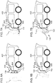
- FIGS. 8A to 8C schematically show a third embodiment of the airbag assembly 106. More specifically, show the Figures 8A, 8B and 8C a side view, a top view and a vehicle-center sectional view of the airbag assembly 106 for a commercial vehicle.
- EU Directive 2015/719 amending Directive 96/53 / EC which regulates the dimensions of commercial vehicles, provides for longer vehicle lengths in relation to certain structures on the outer skin of commercial vehicles. For example, it should be possible to exceed the previously valid vehicle lengths for aerodynamic improvements of the vehicles. This will also allow structures to reduce the severity of accidents, for example according to Reason (5) in Directive 2015/719.
- This integration of the airbag assembly 106 is not only possible in previous cabs. Also, with the changed cab geometries, further or simplified embodiments of the installation of the airbag arrangement 106 are possible.
- the impact section 112 is in the filled state parallel to the front region 402, preferably over the entire width of the motor vehicle 400. On the sides, the impact section 112 extends as side sections beyond the width of the motor vehicle and is curved forward in the direction of travel. The clearance 116 formed by the concave impact portion 112 is closed in the traveling direction after the second timing by the retaining portion 114.
- the impact portion 112 of the bottom portion 120 protrudes in the direction of travel.
- the space 116 is surrounded by the impact portion 112 on four sides, which impart special dimensional stability to the impact portion 112.
- the third exemplary embodiment of the airbag arrangement 106 is described for a commercial vehicle, such an airbag arrangement 106 can be used with any motor vehicle 400, in particular with (at least substantially) vertical front area 402.
- each embodiment of the airbag assembly 106 may also be disposed on one side of the motor vehicle 400.
- the controller 110 may be configured with respect to the laterally disposed airbag assembly 106 for detecting a transient road user.
- a road user 1 of the cross traffic for example, a pedestrian entering the roadway
- the airbag arrangement 106 can be arranged laterally in front of the wheel arches and / or in front of an accessible free space between the wheel axles.
- the airbag arrangement 106 in particular its impact section 112 and / or retaining section 114, can be designed in one piece or in several parts.
- a one-piece design can allow a continuous protection area for the road user 1.
- the multi-part design can be used depending on the width of the motor vehicle.
- the multi-part design can improve the dimensional stability of the filled airbag assembly by partitions or a reduced distance between the partitions.
- the multi-part design can comprise a plurality of gas generators (for example at least one gas generator per partial area), for a particularly short duration of deployment of the section.
- Fig. 9 shows (but is not limited to) a one-piece embodiment of both the impact portion 112 and the retention portion 114 in the third embodiment.
- the retention portion 114 may deploy from the second point in time from the leading edge of the bottom portion 120.
- Fig. 10 shows (but not limited to) a two-part embodiment of both the impact portion 112 and the retaining portion 114 in the third embodiment.
- Each portion of the retaining portion 114 is connected to the respective side portions at the impact portion 112 over the entire height of the retaining portion 114.
- the retaining portion 114 is connected at each height to the respective side portion at at least two locations.
- the retaining portion 114 is given a stiff transverse orientation from the side portions to the vehicle centerline. Further, the retaining portion 114, even without mechanical connection to the bottom portion 120, forces transmitted against the direction of travel to the road user 1.
- each section each comprise a gas generator which is in signal communication with the device 100 via the driver interface 108.
- the retention portion 114 (and optionally one or each portion of the retention portion 114) is in fluid communication with the impact portion 112 via a plurality of ports.
- passage openings distributed over the entire height of the retention section 114 allow propellant gas to flow from the impact section 112 into the retention section 114 at the second time.
- FIG. 10 schematically shows such a flow through curved arrows.
- passage openings are arranged between the bottom section 120 and the retaining section 114 over the entire width of the retaining section 114, which allow propellant gas to flow from the impact section 112 into the retaining section 114.
- FIG. 9 schematically shows such a flow through curved arrows.
Landscapes
- Engineering & Computer Science (AREA)
- Mechanical Engineering (AREA)
- Traffic Control Systems (AREA)
- Air Bags (AREA)
Applications Claiming Priority (1)
| Application Number | Priority Date | Filing Date | Title |
|---|---|---|---|
| DE102017112276.1A DE102017112276A1 (de) | 2017-06-02 | 2017-06-02 | Technik zur Verletzungsminderung bei asymmetrischen Kollisionen |
Publications (2)
| Publication Number | Publication Date |
|---|---|
| EP3409542A1 true EP3409542A1 (fr) | 2018-12-05 |
| EP3409542B1 EP3409542B1 (fr) | 2020-02-05 |
Family
ID=62200261
Family Applications (1)
| Application Number | Title | Priority Date | Filing Date |
|---|---|---|---|
| EP18172520.1A Active EP3409542B1 (fr) | 2017-06-02 | 2018-05-16 | Technique permettant de limiter les dommages lors des collisions asymétriques |
Country Status (2)
| Country | Link |
|---|---|
| EP (1) | EP3409542B1 (fr) |
| DE (1) | DE102017112276A1 (fr) |
Cited By (7)
| Publication number | Priority date | Publication date | Assignee | Title |
|---|---|---|---|---|
| CN109591755A (zh) * | 2019-01-14 | 2019-04-09 | 长沙理工大学 | 一种高速轿车保护人地碰撞损伤的方法 |
| CN110371113A (zh) * | 2019-07-28 | 2019-10-25 | 南京视莱尔汽车电子有限公司 | 一种自动驾驶汽车测距反馈装置 |
| CN111907463A (zh) * | 2020-07-10 | 2020-11-10 | 张存劳 | 一种全过程行人安全气囊系统 |
| WO2021204244A1 (fr) * | 2020-04-10 | 2021-10-14 | 采埃孚汽车科技(上海)有限公司 | Module de coussin de sécurité gonflable, système de sécurité, procédé d'amélioration de la compatibilité routière d'un véhicule, et support |
| WO2022148778A1 (fr) | 2021-01-08 | 2022-07-14 | Envirprod | Module de protection pour vehicule automobile destine a proteger un pieton lors d'un choc |
| FR3118740A1 (fr) | 2021-01-08 | 2022-07-15 | Envirprod | Module de protection pour vehicule automobile destine a proteger un pieton lors d’un choc |
| CN116848023A (zh) * | 2021-01-08 | 2023-10-03 | 英纬普罗德 | 用于在发生碰撞时保护行人的机动车辆保护模块 |
Families Citing this family (2)
| Publication number | Priority date | Publication date | Assignee | Title |
|---|---|---|---|---|
| JP6909440B2 (ja) * | 2017-09-19 | 2021-07-28 | いすゞ自動車株式会社 | 車両の歩行者保護装置 |
| DE102021207126A1 (de) * | 2021-07-07 | 2023-01-12 | Zf Friedrichshafen Ag | Verfahren zum Betreiben eines Sicherheitssystems eines Fahrzeugs, Computerprogrammprodukt, Vorrichtung und Steuergerät |
Citations (4)
| Publication number | Priority date | Publication date | Assignee | Title |
|---|---|---|---|---|
| DE10121630A1 (de) * | 2001-05-03 | 2002-11-07 | Rach Barbara | Sicherheitseinrichtung an einem Fahrzeug, insbesondere an einem Kraftfahrzeug, zum Schutz von Fußgängern oder dergleichen |
| DE10356572A1 (de) * | 2003-12-04 | 2005-06-30 | Rach, Barbara | Sicherheitseinrichtung an einem Fahrzeug, insbesondere an einem Kraftfahrzeug zum Schutz von Fußgängern |
| DE102004027171A1 (de) * | 2004-06-03 | 2005-12-22 | Daimlerchrysler Ag | Schutzeinrichtung an Kraftfahrzeugen |
| US9802568B1 (en) * | 2015-09-04 | 2017-10-31 | Waymo Llc | Interlocking vehicle airbags |
Family Cites Families (10)
| Publication number | Priority date | Publication date | Assignee | Title |
|---|---|---|---|---|
| JP3963055B2 (ja) * | 1999-01-29 | 2007-08-22 | 日産自動車株式会社 | 歩行者保護用エアバッグ装置 |
| DE19935342B4 (de) * | 1999-07-28 | 2014-09-04 | Volkswagen Ag | Fahrzeug mit einer Sicherheitseinrichtung an stoßgefährdenden Fahrzeugteilen der Außenhaut |
| DE10059202A1 (de) * | 2000-11-29 | 2002-07-11 | Rach Barbara | Sicherheitseinrichtung an einem Kraftfahrzeug zum Schutz von Fußgängern |
| DE10059203A1 (de) * | 2000-11-29 | 2002-07-11 | Rach Barbara | Sicherheitseinrichtung an einem Fahrzeug, insbesondere einem Kraftfahrzeug, zum Schutz von Fußgängern |
| DE10213178A1 (de) * | 2001-07-07 | 2003-02-13 | Rach Barbara | Sicherheitseinrichtung an einem Fahrzeug, insbesondere an einem Kraftfahrzeug, zum Schutz von Fußgängern, Radfahrer oder dergleichen |
| DE10233593A1 (de) * | 2002-07-19 | 2004-02-19 | Takata-Petri Ag | Vorrichtung zum Schutz einer sich im Außenbereich eines Kraftfahrzeugs befindlichen Person |
| DE10235414A1 (de) * | 2002-08-02 | 2004-02-12 | Robert Bosch Gmbh | Verfahren und Vorrichtung zur Ermittlung des Bevorstehens einer unausweichbaren Kollision |
| DE10239352A1 (de) * | 2002-08-28 | 2004-03-11 | Rach, Barbara | Sicherheitseinrichtung für ein Fahrzeug zum Schutz von Fußgängern oder dergleichen |
| JP3975866B2 (ja) | 2002-08-30 | 2007-09-12 | 豊田合成株式会社 | 歩行者保護用エアバッグ装置 |
| US9340178B1 (en) | 2013-12-04 | 2016-05-17 | Google Inc. | Adhesive vehicle front end for mitigation of secondary pedestrian impact |
-
2017
- 2017-06-02 DE DE102017112276.1A patent/DE102017112276A1/de not_active Withdrawn
-
2018
- 2018-05-16 EP EP18172520.1A patent/EP3409542B1/fr active Active
Patent Citations (4)
| Publication number | Priority date | Publication date | Assignee | Title |
|---|---|---|---|---|
| DE10121630A1 (de) * | 2001-05-03 | 2002-11-07 | Rach Barbara | Sicherheitseinrichtung an einem Fahrzeug, insbesondere an einem Kraftfahrzeug, zum Schutz von Fußgängern oder dergleichen |
| DE10356572A1 (de) * | 2003-12-04 | 2005-06-30 | Rach, Barbara | Sicherheitseinrichtung an einem Fahrzeug, insbesondere an einem Kraftfahrzeug zum Schutz von Fußgängern |
| DE102004027171A1 (de) * | 2004-06-03 | 2005-12-22 | Daimlerchrysler Ag | Schutzeinrichtung an Kraftfahrzeugen |
| US9802568B1 (en) * | 2015-09-04 | 2017-10-31 | Waymo Llc | Interlocking vehicle airbags |
Cited By (7)
| Publication number | Priority date | Publication date | Assignee | Title |
|---|---|---|---|---|
| CN109591755A (zh) * | 2019-01-14 | 2019-04-09 | 长沙理工大学 | 一种高速轿车保护人地碰撞损伤的方法 |
| CN110371113A (zh) * | 2019-07-28 | 2019-10-25 | 南京视莱尔汽车电子有限公司 | 一种自动驾驶汽车测距反馈装置 |
| WO2021204244A1 (fr) * | 2020-04-10 | 2021-10-14 | 采埃孚汽车科技(上海)有限公司 | Module de coussin de sécurité gonflable, système de sécurité, procédé d'amélioration de la compatibilité routière d'un véhicule, et support |
| CN111907463A (zh) * | 2020-07-10 | 2020-11-10 | 张存劳 | 一种全过程行人安全气囊系统 |
| WO2022148778A1 (fr) | 2021-01-08 | 2022-07-14 | Envirprod | Module de protection pour vehicule automobile destine a proteger un pieton lors d'un choc |
| FR3118740A1 (fr) | 2021-01-08 | 2022-07-15 | Envirprod | Module de protection pour vehicule automobile destine a proteger un pieton lors d’un choc |
| CN116848023A (zh) * | 2021-01-08 | 2023-10-03 | 英纬普罗德 | 用于在发生碰撞时保护行人的机动车辆保护模块 |
Also Published As
| Publication number | Publication date |
|---|---|
| EP3409542B1 (fr) | 2020-02-05 |
| DE102017112276A1 (de) | 2018-12-06 |
Similar Documents
| Publication | Publication Date | Title |
|---|---|---|
| EP3409542B1 (fr) | Technique permettant de limiter les dommages lors des collisions asymétriques | |
| EP3107766B1 (fr) | Système et methode de sécurité de véhicule | |
| EP1963149B1 (fr) | Dispositif de securite pour vehicules automobiles | |
| DE102004058176A1 (de) | Pre-Safe-Aktivierung eines Fahrzeugs | |
| WO2006045259A1 (fr) | Procede pour ameliorer la securite d'usagers de la route impliques dans un accident prevu par anticipation | |
| DE102011109697A1 (de) | Verfahren zum Betreiben eines Kraftfahrzeuges und Fahrerassistenzsystem zur Durchführung des Verfahrens | |
| DE102012005867B4 (de) | Verfahren zum präventiven Schutz von Insassen eines Fahrzeugs vor einer Kollision | |
| EP2724910B1 (fr) | Procédé et dispositif de réduction des conséquences médicales d'accidents pour des accidents inévitables provenant du trafic transversal | |
| DE102017201936A1 (de) | Verfahren zur Reduzierung eines Kollisionsschadens | |
| WO2006058718A1 (fr) | Procede pour systeme de protection a action preventive, dans une automobile equipee d'un systeme de detection de distance | |
| DE102011120500B4 (de) | Verfahren zum Betreiben eines Kraftfahrzeugs und Kraftfahrzeug | |
| EP2526000B1 (fr) | Procédé et dispositif permettant de réduire les conséquences d'un accident sur un occupant de véhicule | |
| DE102004018394B4 (de) | Insassenschutzsystem | |
| DE4114016A1 (de) | Sicherheitseinrichtung fuer ein kraftfahrzeug | |
| DE102007030995B4 (de) | Steuergerät zur Ansteuerung einer Aktuatorik für einen Personenschutz für ein Fahrzeug, Vorrichtung zum Personenschutz für ein Fahrzeug und Verfahren zur Ansteuerung einer Aktuatorik für einen Personenschutz für ein Fahrzeug | |
| EP3842293B1 (fr) | Dispositif de protection contre les chocs | |
| EP3431319B1 (fr) | Dispositif de réduction des suites d'une collision pour véhicules | |
| DE10224831B4 (de) | Kraftfahrzeug und Verfahren zur Reduzierung der Belastung von Insassen eines Kraftfahrzeugs bei einem Zusammenstoss mit einem Hindernis | |
| DE102016002458A1 (de) | Fahrzeugfront für einen Kraftwagen | |
| WO2005000635A1 (fr) | Systeme de deceleration de pre-impact destine a des objets en deplacement | |
| DE102017222389B4 (de) | Verfahren zum Betreiben eines Kraftfahrzeugs bei Erkennen eines unvermeidbaren Seitenaufpralls auf ein fahrzeugfremdes Objekt | |
| DE102017209061B4 (de) | Verfahren zum Reduzieren einer Auswirkung auf ein Kraftfahrzeug bei einem Unterfahren einer Barriere, Unterfahrschutzeinrichtung, und Kraftfahrzeug | |
| DE102022211682A1 (de) | Assistenzsystem für ein Fahrzeug sowie Verfahren zum Betrieb eines Assistenzsystems für ein Fahrzeug sowie Fahrzeug | |
| DE10026371A1 (de) | Verfahren und Vorrichtung zur Verzögerung eines Kraftfahrzeuges | |
| DE102018216379A1 (de) | Insassenschutzsystem für ein Fahrzeug mit einem Sicherheitsgurt sowie Verfahren zum Betrieb eines solchen Insassenschutzsystems |
Legal Events
| Date | Code | Title | Description |
|---|---|---|---|
| PUAI | Public reference made under article 153(3) epc to a published international application that has entered the european phase |
Free format text: ORIGINAL CODE: 0009012 |
|
| STAA | Information on the status of an ep patent application or granted ep patent |
Free format text: STATUS: THE APPLICATION HAS BEEN PUBLISHED |
|
| AK | Designated contracting states |
Kind code of ref document: A1 Designated state(s): AL AT BE BG CH CY CZ DE DK EE ES FI FR GB GR HR HU IE IS IT LI LT LU LV MC MK MT NL NO PL PT RO RS SE SI SK SM TR |
|
| AX | Request for extension of the european patent |
Extension state: BA ME |
|
| STAA | Information on the status of an ep patent application or granted ep patent |
Free format text: STATUS: REQUEST FOR EXAMINATION WAS MADE |
|
| 17P | Request for examination filed |
Effective date: 20190517 |
|
| RBV | Designated contracting states (corrected) |
Designated state(s): AL AT BE BG CH CY CZ DE DK EE ES FI FR GB GR HR HU IE IS IT LI LT LU LV MC MK MT NL NO PL PT RO RS SE SI SK SM TR |
|
| RAP1 | Party data changed (applicant data changed or rights of an application transferred) |
Owner name: MAN TRUCK & BUS SE |
|
| GRAP | Despatch of communication of intention to grant a patent |
Free format text: ORIGINAL CODE: EPIDOSNIGR1 |
|
| STAA | Information on the status of an ep patent application or granted ep patent |
Free format text: STATUS: GRANT OF PATENT IS INTENDED |
|
| INTG | Intention to grant announced |
Effective date: 20191018 |
|
| GRAS | Grant fee paid |
Free format text: ORIGINAL CODE: EPIDOSNIGR3 |
|
| GRAA | (expected) grant |
Free format text: ORIGINAL CODE: 0009210 |
|
| STAA | Information on the status of an ep patent application or granted ep patent |
Free format text: STATUS: THE PATENT HAS BEEN GRANTED |
|
| AK | Designated contracting states |
Kind code of ref document: B1 Designated state(s): AL AT BE BG CH CY CZ DE DK EE ES FI FR GB GR HR HU IE IS IT LI LT LU LV MC MK MT NL NO PL PT RO RS SE SI SK SM TR |
|
| REG | Reference to a national code |
Ref country code: GB Ref legal event code: FG4D Free format text: NOT ENGLISH |
|
| REG | Reference to a national code |
Ref country code: AT Ref legal event code: REF Ref document number: 1229681 Country of ref document: AT Kind code of ref document: T Effective date: 20200215 |
|
| REG | Reference to a national code |
Ref country code: DE Ref legal event code: R096 Ref document number: 502018000721 Country of ref document: DE |
|
| REG | Reference to a national code |
Ref country code: IE Ref legal event code: FG4D Free format text: LANGUAGE OF EP DOCUMENT: GERMAN |
|
| REG | Reference to a national code |
Ref country code: CH Ref legal event code: EP |
|
| REG | Reference to a national code |
Ref country code: NL Ref legal event code: FP |
|
| REG | Reference to a national code |
Ref country code: SE Ref legal event code: TRGR |
|
| PG25 | Lapsed in a contracting state [announced via postgrant information from national office to epo] |
Ref country code: RS Free format text: LAPSE BECAUSE OF FAILURE TO SUBMIT A TRANSLATION OF THE DESCRIPTION OR TO PAY THE FEE WITHIN THE PRESCRIBED TIME-LIMIT Effective date: 20200205 Ref country code: PT Free format text: LAPSE BECAUSE OF FAILURE TO SUBMIT A TRANSLATION OF THE DESCRIPTION OR TO PAY THE FEE WITHIN THE PRESCRIBED TIME-LIMIT Effective date: 20200628 Ref country code: NO Free format text: LAPSE BECAUSE OF FAILURE TO SUBMIT A TRANSLATION OF THE DESCRIPTION OR TO PAY THE FEE WITHIN THE PRESCRIBED TIME-LIMIT Effective date: 20200505 Ref country code: FI Free format text: LAPSE BECAUSE OF FAILURE TO SUBMIT A TRANSLATION OF THE DESCRIPTION OR TO PAY THE FEE WITHIN THE PRESCRIBED TIME-LIMIT Effective date: 20200205 |
|
| REG | Reference to a national code |
Ref country code: LT Ref legal event code: MG4D |
|
| PG25 | Lapsed in a contracting state [announced via postgrant information from national office to epo] |
Ref country code: BG Free format text: LAPSE BECAUSE OF FAILURE TO SUBMIT A TRANSLATION OF THE DESCRIPTION OR TO PAY THE FEE WITHIN THE PRESCRIBED TIME-LIMIT Effective date: 20200505 Ref country code: GR Free format text: LAPSE BECAUSE OF FAILURE TO SUBMIT A TRANSLATION OF THE DESCRIPTION OR TO PAY THE FEE WITHIN THE PRESCRIBED TIME-LIMIT Effective date: 20200506 Ref country code: HR Free format text: LAPSE BECAUSE OF FAILURE TO SUBMIT A TRANSLATION OF THE DESCRIPTION OR TO PAY THE FEE WITHIN THE PRESCRIBED TIME-LIMIT Effective date: 20200205 Ref country code: IS Free format text: LAPSE BECAUSE OF FAILURE TO SUBMIT A TRANSLATION OF THE DESCRIPTION OR TO PAY THE FEE WITHIN THE PRESCRIBED TIME-LIMIT Effective date: 20200605 Ref country code: LV Free format text: LAPSE BECAUSE OF FAILURE TO SUBMIT A TRANSLATION OF THE DESCRIPTION OR TO PAY THE FEE WITHIN THE PRESCRIBED TIME-LIMIT Effective date: 20200205 |
|
| PG25 | Lapsed in a contracting state [announced via postgrant information from national office to epo] |
Ref country code: SK Free format text: LAPSE BECAUSE OF FAILURE TO SUBMIT A TRANSLATION OF THE DESCRIPTION OR TO PAY THE FEE WITHIN THE PRESCRIBED TIME-LIMIT Effective date: 20200205 Ref country code: LT Free format text: LAPSE BECAUSE OF FAILURE TO SUBMIT A TRANSLATION OF THE DESCRIPTION OR TO PAY THE FEE WITHIN THE PRESCRIBED TIME-LIMIT Effective date: 20200205 Ref country code: RO Free format text: LAPSE BECAUSE OF FAILURE TO SUBMIT A TRANSLATION OF THE DESCRIPTION OR TO PAY THE FEE WITHIN THE PRESCRIBED TIME-LIMIT Effective date: 20200205 Ref country code: DK Free format text: LAPSE BECAUSE OF FAILURE TO SUBMIT A TRANSLATION OF THE DESCRIPTION OR TO PAY THE FEE WITHIN THE PRESCRIBED TIME-LIMIT Effective date: 20200205 Ref country code: CZ Free format text: LAPSE BECAUSE OF FAILURE TO SUBMIT A TRANSLATION OF THE DESCRIPTION OR TO PAY THE FEE WITHIN THE PRESCRIBED TIME-LIMIT Effective date: 20200205 Ref country code: EE Free format text: LAPSE BECAUSE OF FAILURE TO SUBMIT A TRANSLATION OF THE DESCRIPTION OR TO PAY THE FEE WITHIN THE PRESCRIBED TIME-LIMIT Effective date: 20200205 Ref country code: SM Free format text: LAPSE BECAUSE OF FAILURE TO SUBMIT A TRANSLATION OF THE DESCRIPTION OR TO PAY THE FEE WITHIN THE PRESCRIBED TIME-LIMIT Effective date: 20200205 Ref country code: ES Free format text: LAPSE BECAUSE OF FAILURE TO SUBMIT A TRANSLATION OF THE DESCRIPTION OR TO PAY THE FEE WITHIN THE PRESCRIBED TIME-LIMIT Effective date: 20200205 |
|
| REG | Reference to a national code |
Ref country code: DE Ref legal event code: R097 Ref document number: 502018000721 Country of ref document: DE |
|
| PLBE | No opposition filed within time limit |
Free format text: ORIGINAL CODE: 0009261 |
|
| STAA | Information on the status of an ep patent application or granted ep patent |
Free format text: STATUS: NO OPPOSITION FILED WITHIN TIME LIMIT |
|
| 26N | No opposition filed |
Effective date: 20201106 |
|
| PG25 | Lapsed in a contracting state [announced via postgrant information from national office to epo] |
Ref country code: MC Free format text: LAPSE BECAUSE OF FAILURE TO SUBMIT A TRANSLATION OF THE DESCRIPTION OR TO PAY THE FEE WITHIN THE PRESCRIBED TIME-LIMIT Effective date: 20200205 |
|
| PG25 | Lapsed in a contracting state [announced via postgrant information from national office to epo] |
Ref country code: SI Free format text: LAPSE BECAUSE OF FAILURE TO SUBMIT A TRANSLATION OF THE DESCRIPTION OR TO PAY THE FEE WITHIN THE PRESCRIBED TIME-LIMIT Effective date: 20200205 Ref country code: PL Free format text: LAPSE BECAUSE OF FAILURE TO SUBMIT A TRANSLATION OF THE DESCRIPTION OR TO PAY THE FEE WITHIN THE PRESCRIBED TIME-LIMIT Effective date: 20200205 |
|
| REG | Reference to a national code |
Ref country code: BE Ref legal event code: MM Effective date: 20200531 |
|
| PG25 | Lapsed in a contracting state [announced via postgrant information from national office to epo] |
Ref country code: LU Free format text: LAPSE BECAUSE OF NON-PAYMENT OF DUE FEES Effective date: 20200516 |
|
| PG25 | Lapsed in a contracting state [announced via postgrant information from national office to epo] |
Ref country code: IE Free format text: LAPSE BECAUSE OF NON-PAYMENT OF DUE FEES Effective date: 20200516 |
|
| PG25 | Lapsed in a contracting state [announced via postgrant information from national office to epo] |
Ref country code: BE Free format text: LAPSE BECAUSE OF NON-PAYMENT OF DUE FEES Effective date: 20200531 |
|
| REG | Reference to a national code |
Ref country code: CH Ref legal event code: PL |
|
| PG25 | Lapsed in a contracting state [announced via postgrant information from national office to epo] |
Ref country code: LI Free format text: LAPSE BECAUSE OF NON-PAYMENT OF DUE FEES Effective date: 20210531 Ref country code: CH Free format text: LAPSE BECAUSE OF NON-PAYMENT OF DUE FEES Effective date: 20210531 |
|
| PG25 | Lapsed in a contracting state [announced via postgrant information from national office to epo] |
Ref country code: TR Free format text: LAPSE BECAUSE OF FAILURE TO SUBMIT A TRANSLATION OF THE DESCRIPTION OR TO PAY THE FEE WITHIN THE PRESCRIBED TIME-LIMIT Effective date: 20200205 Ref country code: MT Free format text: LAPSE BECAUSE OF FAILURE TO SUBMIT A TRANSLATION OF THE DESCRIPTION OR TO PAY THE FEE WITHIN THE PRESCRIBED TIME-LIMIT Effective date: 20200205 Ref country code: CY Free format text: LAPSE BECAUSE OF FAILURE TO SUBMIT A TRANSLATION OF THE DESCRIPTION OR TO PAY THE FEE WITHIN THE PRESCRIBED TIME-LIMIT Effective date: 20200205 |
|
| PG25 | Lapsed in a contracting state [announced via postgrant information from national office to epo] |
Ref country code: MK Free format text: LAPSE BECAUSE OF FAILURE TO SUBMIT A TRANSLATION OF THE DESCRIPTION OR TO PAY THE FEE WITHIN THE PRESCRIBED TIME-LIMIT Effective date: 20200205 Ref country code: AL Free format text: LAPSE BECAUSE OF FAILURE TO SUBMIT A TRANSLATION OF THE DESCRIPTION OR TO PAY THE FEE WITHIN THE PRESCRIBED TIME-LIMIT Effective date: 20200205 |
|
| GBPC | Gb: european patent ceased through non-payment of renewal fee |
Effective date: 20220516 |
|
| PG25 | Lapsed in a contracting state [announced via postgrant information from national office to epo] |
Ref country code: GB Free format text: LAPSE BECAUSE OF NON-PAYMENT OF DUE FEES Effective date: 20220516 |
|
| PGFP | Annual fee paid to national office [announced via postgrant information from national office to epo] |
Ref country code: SE Payment date: 20230317 Year of fee payment: 6 |
|
| PGFP | Annual fee paid to national office [announced via postgrant information from national office to epo] |
Ref country code: NL Payment date: 20230525 Year of fee payment: 6 Ref country code: IT Payment date: 20230525 Year of fee payment: 6 Ref country code: FR Payment date: 20230523 Year of fee payment: 6 Ref country code: DE Payment date: 20230530 Year of fee payment: 6 |