EP3409526A1 - Display device of a driver assistance system for a motor vehicle - Google Patents
Display device of a driver assistance system for a motor vehicle Download PDFInfo
- Publication number
- EP3409526A1 EP3409526A1 EP18172220.8A EP18172220A EP3409526A1 EP 3409526 A1 EP3409526 A1 EP 3409526A1 EP 18172220 A EP18172220 A EP 18172220A EP 3409526 A1 EP3409526 A1 EP 3409526A1
- Authority
- EP
- European Patent Office
- Prior art keywords
- speed
- display
- bremsomat
- function
- scale
- Prior art date
- Legal status (The legal status is an assumption and is not a legal conclusion. Google has not performed a legal analysis and makes no representation as to the accuracy of the status listed.)
- Granted
Links
- 239000003550 marker Substances 0.000 claims description 7
- 230000008859 change Effects 0.000 claims description 6
- 230000004913 activation Effects 0.000 abstract description 2
- 230000006978 adaptation Effects 0.000 description 7
- 230000003044 adaptive effect Effects 0.000 description 4
- 230000008901 benefit Effects 0.000 description 4
- 230000001276 controlling effect Effects 0.000 description 4
- 239000000446 fuel Substances 0.000 description 3
- 230000000694 effects Effects 0.000 description 2
- 230000000007 visual effect Effects 0.000 description 2
- 238000004891 communication Methods 0.000 description 1
- 230000007423 decrease Effects 0.000 description 1
- 230000001419 dependent effect Effects 0.000 description 1
- 238000001514 detection method Methods 0.000 description 1
- 230000007613 environmental effect Effects 0.000 description 1
- 230000010354 integration Effects 0.000 description 1
- 238000000034 method Methods 0.000 description 1
- 238000012986 modification Methods 0.000 description 1
- 230000004048 modification Effects 0.000 description 1
- 230000001105 regulatory effect Effects 0.000 description 1
- 230000004044 response Effects 0.000 description 1
- 238000012876 topography Methods 0.000 description 1
Images

Classifications
-
- B—PERFORMING OPERATIONS; TRANSPORTING
- B60—VEHICLES IN GENERAL
- B60K—ARRANGEMENT OR MOUNTING OF PROPULSION UNITS OR OF TRANSMISSIONS IN VEHICLES; ARRANGEMENT OR MOUNTING OF PLURAL DIVERSE PRIME-MOVERS IN VEHICLES; AUXILIARY DRIVES FOR VEHICLES; INSTRUMENTATION OR DASHBOARDS FOR VEHICLES; ARRANGEMENTS IN CONNECTION WITH COOLING, AIR INTAKE, GAS EXHAUST OR FUEL SUPPLY OF PROPULSION UNITS IN VEHICLES
- B60K35/00—Arrangement of adaptations of instruments
-
- B60K35/213—
-
- B60K35/28—
-
- B60K35/60—
-
- B—PERFORMING OPERATIONS; TRANSPORTING
- B60—VEHICLES IN GENERAL
- B60K—ARRANGEMENT OR MOUNTING OF PROPULSION UNITS OR OF TRANSMISSIONS IN VEHICLES; ARRANGEMENT OR MOUNTING OF PLURAL DIVERSE PRIME-MOVERS IN VEHICLES; AUXILIARY DRIVES FOR VEHICLES; INSTRUMENTATION OR DASHBOARDS FOR VEHICLES; ARRANGEMENTS IN CONNECTION WITH COOLING, AIR INTAKE, GAS EXHAUST OR FUEL SUPPLY OF PROPULSION UNITS IN VEHICLES
- B60K31/00—Vehicle fittings, acting on a single sub-unit only, for automatically controlling vehicle speed, i.e. preventing speed from exceeding an arbitrarily established velocity or maintaining speed at a particular velocity, as selected by the vehicle operator
- B60K2031/0091—Speed limiters or speed cutters
-
- B—PERFORMING OPERATIONS; TRANSPORTING
- B60—VEHICLES IN GENERAL
- B60K—ARRANGEMENT OR MOUNTING OF PROPULSION UNITS OR OF TRANSMISSIONS IN VEHICLES; ARRANGEMENT OR MOUNTING OF PLURAL DIVERSE PRIME-MOVERS IN VEHICLES; AUXILIARY DRIVES FOR VEHICLES; INSTRUMENTATION OR DASHBOARDS FOR VEHICLES; ARRANGEMENTS IN CONNECTION WITH COOLING, AIR INTAKE, GAS EXHAUST OR FUEL SUPPLY OF PROPULSION UNITS IN VEHICLES
- B60K2310/00—Arrangements, adaptations or methods for cruise controls
- B60K2310/22—Displays for target speed
-
- B60K2360/167—
-
- B60K2360/698—
Definitions
- the invention relates to a display device of a driver assistance system of a motor vehicle, comprising a display surface and a control device coupled to the display surface for controlling a display on the display surface.
- the invention further relates to a motor vehicle, in particular a commercial vehicle, with such a display device.
- gauges are used to present the driver with current values concerning the vehicle or the environment. For example, the speed of the vehicle, the speed of the engine, the temperature of the engine or the tank level are displayed. The presentation is often done with so-called “instrument tubes”.
- instrument tubes In modern vehicles so-called “combination instruments” are used to represent the current vehicle or environmental values or images. They have a large screen on which images and virtual instruments can be displayed. In this case, display instruments are represented, for example, as virtual (digital) instrument tubes with a scale ring.
- Modern commercial vehicles in particular used in long-distance traffic, are equipped, for example, with a cruise control system which comprises two speed regulators operating independently of one another.
- a first controller also called cruise control, tempo pilot or cruise control
- cruise control regulates the speed of the vehicle to a first desired speed via the drive train, for example via the fuel supply in the engine.
- This first control function is also referred to as the Tempopilot function in this document.
- a second controller controls via a braking device of the vehicle, the vehicle speed so that a second target speed, which is above the above first target speed of the first controller is not exceeded.
- the brake speed controller preferably ensures that the second setpoint speed is maintained by means of a wear-free retarder brake (also referred to as a regulated retarder) and not by means of the normal service brake.
- This second control function is also referred to below as the Bremsomat function.
- the tempo pilot function thus adjusts the engine torque to maintain a predetermined desired speed of the driver.
- the Bremsomat function initiates a braking effect when driving downhill, where the vehicle accelerates due to its own weight. From the EP 1 288 056 B1 In particular, a method for controlling the vehicle speed in combination with such a Bremsomat- and / or cruise control function is disclosed, wherein the Bremsomat target speed and / or the desired cruise speed are dynamically changed depending on, for example, topography data. As a result, the fuel-saving effect of such cruise control can be further improved.
- a display device of a driver assistance system of a motor vehicle comprising a display surface and a control device coupled to the display surface for controlling a display on the display surface.
- the driver assistance system may be a cruise control system, which in particular comprises a Bremsomat function and a tempo pilot function.
- the control device is set up to display on the display surface a speed indicator (tachometer) for displaying an instantaneous speed of the motor vehicle.
- the control device is further configured, upon activation of a Bremsomat function, to display a Bremsomat speedometer for displaying a set desired speed of the Bremsomat function, the Bremsomat speedometer being integrated into the speedometer display.
- a particular advantage of this approach is that integration of the Bremsomat speedometer into the speedometer allows quick comparison by the driver from the set desired speed of the Bremsomat function with the actual vehicle speed. Thereby, the probability of a misinterpretation of the information can be reduced since the driver can understand the relationship of the various information to each other (eg target speed of the Bremsomat function in relation to the instantaneous speed) without room for interpretation.
- Another important advantage is that it can save display space because different displays are displayed in combination.
- the set target speed of the Bremsomat function is visualized directly on the tachometer or is displayed at the same point on the display area as the speed indicator, eg. B. directly adjacent, adjacent and / or with reference to a scale of the speedometer.
- a brake-commutator function is understood to mean a function which regulates the brake-commutator setpoint speed via a braking device of the vehicle.
- the Bremsomat function is also referred to as the brake speed control system of the motor vehicle.
- the Bremsomat speed indicator can be displayed along a scale of the speedometer, in particular comprises movable marking element.
- the Bremsomat speed indicator can also be formed only by such a marking element.
- the marking element may be a graphic symbol, e.g. B. include an arrow, a triangle, a pictogram or executed as such.
- the marking element is displayed on the scale of the speed display in such a way that the marking element marks a speed on the scale.
- the marker may be displayed at the location of the scale that corresponds to the desired speed of the Bremsomat function. This indicates the desired brake speed.
- the Bremsomat speed indicator may include an alphanumeric value, which is displayed along a scale of the speedometer, indicative of the altitude of the desired brake master speed set.
- the value may be displayed instead of or preferably in addition to the marking element, preferably adjacent to it. This variant requires more display space but further reduces the likelihood of misinterpreting the information because the driver directly presents the information as a value.
- the control device is formed, with activated Bremsomat function and activated tempo pilot function of the motor vehicle on a scale of the speed display, a first marking element that marks a set target speed of a tempo pilot function of the motor vehicle, and a second marking element, the Bremsomat target speed marked to display.
- the first and the second marking element can be visualized differently, eg. B. differ in their color, brightness, lettering, and / or symbol representation. The driver can thus quickly capture both set speeds and the instantaneous speed. A space-saving presentation is possible.
- control device is designed to activate or change the Bremsomat speed display during an adaptive braking operation in continuous braking mode, in particular on a downhill section.
- the Bremsomat target speed is set to the speed that is used when releasing the brake pedal.
- the Bremsomat function can be designed to detect when the service brake pedal is pressed in the downward gradient, the speed which is set when the pedal is released and thus set by the adaptation braking, and determined as a new or changed desired brake speed.
- the Bremsomat target speed is then determined by the retarder of the commercial vehicle, z. B. by metered use of retarder and engine brake, held in the fall.
- the marking element of the Bremsomat speed display which is displayed with the tempo pilot function activated, is visually distinguishable from the marking element of the Bremsomat speedometer, which is displayed when the tempo pilot function is deactivated and after an adaptation braking.
- the visual distinctiveness can be achieved by different color coding. This makes it clear which mode the display refers to.
- control device is further configured to visualize a change in the desired speed of the Bremsomat function caused by an adaptation braking by a corresponding movement of the marking element along the scale of the speed display.
- the driver is intuitively displayed the adaptation of the target speed of the Bremsomat function.
- different marking elements can be used to represent the Bremsomat target speed, which is determined by the matching braking and for displaying the Bremsomat target speed, which is displayed with simultaneously activated Tempopilot function.
- the driver can distinguish these different Bremsomat target speeds better, even if they are not displayed at the same time in the rule, as a fitting brake usually disables the tempo pilot function.
- the display surface of the display device may be a screen on which images and virtual instruments can be displayed.
- the display device can be designed as a combination instrument.
- the display area can also be used for this purpose be to represent an engine speed, the current engine speed is displayed using a scale.
- the controller may be configured to display an area above and below the set tempo pilot setpoint speed along a scale of the speedometer when the tempo pilot function is activated, exploiting a GPS-based tempo pilot function taking into account forward grade and altitude information of the route can be.
- Integrating this range of the GPS-based tempo pilot function above and below the set tempo pilot setpoint speed into the speed display together with the Bremsomat speedometer offers the advantage that another functionally related function or display is structurally set in the same context. Thus, on the one hand, a further space savings can be achieved. On the other hand, the probability of misinterpretation of this information can be reduced because the driver gets presented the information in the logically associated scale.
- an advantageous space-saving variant of this embodiment provides that the area above and below the set speed target speed is represented by a circular arc, in particular by a circular arc which is part of the circle described by the rotatable pointer of the speedometer.
- the range above and below the set tempo pilot setpoint speed can also be displayed in a different format, for example in a column format.
- the range above and below the set tempo pilot target speed may be marked by an upper limit speed above the tempo pilot set speed and a lower limit speed below the tempo pilot set speed.
- marking elements can be used, which visually, z. B. by the color, brightness, lettering, and / or symbol representation of the marking element of Bremsomat speed display are distinguishable.
- the Bremsomat speed display may represent a Bremsomat spread range indicative of possible adjustable values of the desired Bremsomat speed in response to the set tempo pilot setpoint speed.
- the desired speed of the Bremsomat function is usually a fixed value (also referred to as offset or spread) above the setpoint speed of the tempo pilot function when the tempo pilot function is activated. This ensures that the two control systems can work together and independently of each other and do not interfere with each other.
- the Bremsomat spread range indicates the adjustable range of the target speed of Bremsomat function in compliance with the spread / the offset.
- the control device can be designed to use a digital round instrument, also referred to as a virtual round instrument, for displaying the instantaneous speed.
- the digital round instrument has a curved speed scale, in particular a round field scale or semi-circular field scale, and a rotatable pointer whose position on the speed scale indicates the instantaneous speed of the motor vehicle.
- the controller may be configured to use another digital scale instrument to represent the instantaneous velocity, such as by displaying a long-field scale.
- the invention further relates to a motor vehicle, in particular utility vehicle, comprising a display device according to one of the preceding claims.
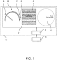
- FIG. 1 schematically shows a display device 1 according to an embodiment of the invention.
- the display device is designed as a combination instrument that has a display surface 2 as a screen.
- the display device 1 further comprises a control device 3 coupled to the display surface 2 for controlling a display of information on the display surface 2.
- the control device 3 is in communication with a driver assistance system, e.g. B. via a vehicle data bus.
- the driver assistance system includes a cruise control system with a Bremsomat function and a tempo pilot function.
- FIG. 1 merely shows, by way of example, a possible division of the advertising area 2, on which two virtual round instruments and between them in a middle central area, a further display area 5 is provided, for example by information of a navigation device or values of the vehicle operating parameters or the environment regarding can be displayed.
- One of the round instruments can be used, for example, to display a speedometer 10 in the form of a virtual tachometer or speedometer.
- the other round instrument can be used for example to form a virtual speed display 4 in the form of a virtual round instrument.
- the term round instrument should also include representations as a semi-circular instrument and generally displays with a curved scale.
- the control device 3 is designed to use a digital rotary instrument as the speed display 10 and to represent the instantaneous speed, comprising a curved speed scale 12 in the form of a half-round field scale and a rotatable pointer 13 whose position on the speed scale 12 indicates the instantaneous speed of the motor vehicle.
- the Bremsomat speed indicator is realized in the embodiment shown by a displayable on the scale 12 of the speedometer 10 marking element 8 or 9.
- the marker 8 or 9 is displayed, depending on whether a tempo pilot function is activated or a fitting braking has been carried out.
- the control device 3 is set up to display two marking elements 8, 11 on a scale of the speed display when the Bremsomat function is activated and at the same time the tempo pilot function of the motor vehicle is activated.
- the marking element 11 marks by its location on the scale 12, the set target speed of a tempo pilot function of the motor vehicle.
- the marking element 8 marks by its location on the scale 12 the set Bremsomat target speed, which is at least one offset value above the set target speed of a tempo pilot function.
- the two marking elements 8, 11 are shown visually differently. They differ, for example, in their color.
- the control device 3 is also designed to activate or change the Bremsomat speed indicator 9 during a matching braking during the continuous braking operation, in particular on a downward slope.
- To change the Bremsomat speed display 9 here means that a value of the setpoint speed of the Bremsomat function that has been changed by the adaptation braking is represented by corresponding adaptation of the position of the marking 9 on the scale 12.
- the adaptation braking can deactivate the tempo pilot function.
- the marker 11 can no longer be displayed when the marker 9 is shown and vice versa.
- an alternative possibility is that during an adaptive braking the tempo pilot function marker 11 is still displayed, but in a visually altered representation, for. B. in a different color.
- the second adjustment drag mark 9 may perform a visible movement along the scale of the speed indication to lower speed values until the changed value of the desired speed corresponding to the matching braking during the matching braking.
- the set before the matching braking target speed of the tempo pilot function can be achieved by pressing an appropriate operating element, eg. As a "Resume" button, reactivated or set.
- the marking element 9 can again perform a visible movement back along the scale of the speed indicator.
- the driver gets the visual indication that when the target speed of the tempo pilot function is reactivated, the setpoint speed of the tempo pilot function, which is still marked via the mark 11, is approached again.
- the marking elements 8 and 9 are in FIG. 2 each represented by an arrow symbol or a triangular shape. By different color coding of the marking elements 8 and 9 it is clarified which mode the display relates to. According to a further variant (not shown), the marking element 9, which displays the Bresomat speed indicator after a fitting braking, for example, also be represented by a pictogram, which schematically represents a commercial vehicle that drives on a similar route.
- the Bremsomat function stores the speed that is driven when releasing the brake pedal (matching braking). The stored value is maintained by metered use of retarder and engine brake in the fall.
- the position of the pointer 13 of the speedometer 10 in FIG. 2 shows a situation after a fitting braking, wherein the target speed thus set the Bremsomat function corresponds to the current speed and is indicated by the Bremsomat speed indicator in the form of the marker 9.
- the controller is configured to display a range 14b above and a range 14a below the set speed pilot setpoint speed when the tempo pilot function is activated along a scale 12 of the speedometer 10, based on a GPS based tempo pilot function taking into account forward grade and altitude information the route can be exploited.
- the regions 14a, 14b thus represent a range of the hysteresis above and below the desired speed 14 of the tempo pilot function 14, which can be exploited by a forward-looking, the preceding topographical route profile considering Tempopilot function.
- the region 14a, 14b is represented in the example shown by a circular arc 14a, 14b.
- the circular arc is part of the circle described by the rotatable pointer 13 of the speedometer 10.
- the area marks by endpoints an upper limit speed 16 above the speed setpoint speed and a lower limit speed 15 below the speed setpoint speed.
Abstract
Die Erfindung betrifft eine Anzeigevorrichtung eines Fahrerassistenzsystems eines Kraftfahrzeugs, umfassend eine Anzeigefläche und eine mit der Anzeigefläche gekoppelte Steuereinrichtung zum Steuern einer Anzeige auf der Anzeigefläche. Die Erfindung betrifft ferner ein Kraftfahrzeug, insbesondere ein Nutzfahrzeug, mit einer derartigen Anzeigevorrichtung. Die Anzeigevorrichtung umfasst ein Fahrerassistenzsystem des Kraftfahrzeugs, umfassend eine Anzeigefläche (2) und eine mit der Anzeigefläche gekoppelte Steuereinrichtung (3) zum Steuern einer Anzeige auf der Anzeigefläche (2). Die Steuereinrichtung (3) ist eingerichtet, auf der Anzeigefläche (2) eine Geschwindigkeitsanzeige (10) zur Darstellung einer Momentangeschwindigkeit des Kraftfahrzeugs anzuzeigen. Die Steuereinrichtung (3) ist ferner eingerichtet, bei Aktivierung einer Bremsomat-Funktion eine Bremsomat-Geschwindigkeitsanzeige (8; 9) zur Darstellung einer eingestellten Sollgeschwindigkeit der Bremsomat-Funktion anzuzeigen. Hierbei ist die die Bremsomat-Geschwindigkeitsanzeige in die Geschwindigkeitsanzeige integriert.

Description
Die Erfindung betrifft eine Anzeigevorrichtung eines Fahrerassistenzsystems eines Kraftfahrzeugs, umfassend eine Anzeigefläche und eine mit der Anzeigefläche gekoppelte Steuereinrichtung zum Steuern einer Anzeige auf der Anzeigefläche. Die Erfindung betrifft ferner ein Kraftfahrzeug, insbesondere ein Nutzfahrzeug, mit einer derartigen Anzeigevorrichtung.The invention relates to a display device of a driver assistance system of a motor vehicle, comprising a display surface and a control device coupled to the display surface for controlling a display on the display surface. The invention further relates to a motor vehicle, in particular a commercial vehicle, with such a display device.
In Fahrzeugen und insbesondere in Kraftfahrzeugen werden Anzeigeinstrumente benutzt, um dem Fahrer aktuelle Werte, das Fahrzeug oder die Umgebung betreffend, darzustellen. Beispielsweise werden so die Geschwindigkeit des Fahrzeugs, die Drehzahl des Motors, die Temperatur des Motors oder der Tankfüllstand dargestellt. Die Darstellung erfolgt häufig mit sogenannten "Instrumententuben". In modernen Fahrzeugen werden zur Darstellung der aktuellen Fahrzeug- bzw. Umgebungswerte oder -bilder sogenannte "Kombi-Instrumente" verwendet. Sie besitzen einen großen Bildschirm, auf dem Bilder und virtuelle Instrumente dargestellt werden können. Dabei werden Anzeigeinstrumente beispielsweise als virtuelle (digitale) Instrumententuben mit einem Skalenring dargestellt.In vehicles, and especially in motor vehicles, gauges are used to present the driver with current values concerning the vehicle or the environment. For example, the speed of the vehicle, the speed of the engine, the temperature of the engine or the tank level are displayed. The presentation is often done with so-called "instrument tubes". In modern vehicles so-called "combination instruments" are used to represent the current vehicle or environmental values or images. They have a large screen on which images and virtual instruments can be displayed. In this case, display instruments are represented, for example, as virtual (digital) instrument tubes with a scale ring.
Nutzfahrzeuge besitzen im Gegensatz zu herkömmlichen Fahrzeugen Assistenzsysteme für Spezialfunktionen, wie z. B. einen Retarder, eine Bremsomat-Funktion, oder eine Anpassbremsung (bergab).Commercial vehicles have in contrast to conventional vehicles assistance systems for special functions, such. As a retarder, a Bremsomat function, or a fitting braking (downhill).
Moderne, insbesondere im Fernverkehr eingesetzte Nutzfahrzeuge, sind beispielsweise mit einer Geschwindigkeitsregelanlage ausgestattet, die zwei unabhängig voneinander arbeitende Geschwindigkeitsregler umfasst. Ein erster Regler (auch Fahrgeschwindigkeitsregler, Tempopilot oder Tempomat® genannt) regelt über den Antriebsstrang, beispielsweise über die Kraftstoffzufuhr im Motor, die Geschwindigkeit des Fahrzeugs auf eine erste Sollgeschwindigkeit. Diese erste Regelfunktion wird in diesem Dokument auch als Tempopilot-Funktion bezeichnet.Modern commercial vehicles, in particular used in long-distance traffic, are equipped, for example, with a cruise control system which comprises two speed regulators operating independently of one another. A first controller (also called cruise control, tempo pilot or cruise control) regulates the speed of the vehicle to a first desired speed via the drive train, for example via the fuel supply in the engine. This first control function is also referred to as the Tempopilot function in this document.
Ein zweiter Regler (auch Bremsgeschwindigkeitsregler oder Bremsomat genannt) regelt über eine Bremseinrichtung des Fahrzeugs die Fahrzeuggeschwindigkeit so, dass eine zweite Sollgeschwindigkeit, die über der vorstehend genannten ersten Sollgeschwindigkeit des ersten Reglers liegt, nicht überschritten wird. Dadurch kann verhindert werden, dass Fahrzeuge, insbesondere schwere Nutzfahrzeuge, bei Fahrten auf Gefällestrecken auch ohne Kraftstoffzufuhr, d. h. im nicht befeuerten Betrieb, durch den Hangabtrieb zu weit über die Wunschgeschwindigkeit (erste Sollgeschwindigkeit) hinaus beschleunigen. Vorzugsweise stellt der Bremsgeschwindigkeitsregler das Einhalten der zweiten Sollgeschwindigkeit mittels einer verschleißfreien Dauerbremse (auch als geregelte Dauerbremse bezeichnet) sicher und nicht mittels der normalen Betriebsbremse. Diese zweite Regelfunktion wird nachfolgend auch als Bremsomat-Funktion bezeichnet.A second controller (also called brake speed controller or Bremsomat) controls via a braking device of the vehicle, the vehicle speed so that a second target speed, which is above the above first target speed of the first controller is not exceeded. This can prevent vehicles, especially heavy commercial vehicles, when traveling on downhill slopes without fuel supply, ie in non-fired operation, by the downgrade too far above the desired speed accelerate (first target speed) out. The brake speed controller preferably ensures that the second setpoint speed is maintained by means of a wear-free retarder brake (also referred to as a regulated retarder) and not by means of the normal service brake. This second control function is also referred to below as the Bremsomat function.
Die Tempopilot-Funktion passt somit das Motormoment an, um eine vorgegebene Wunschgeschwindigkeit des Fahrers einzuhalten. Die Bremsomat-Funktion leitet alternativ eine Bremswirkung bei Bergabfahrten ein, bei denen das Fahrzeug aufgrund seines eigenen Gewichts beschleunigt. Aus der
Aus der Praxis ist es bekannt, zur Anzeige von Informationen einer derartigen Bremsomat-Funktion in Kombi-Instrumenten mit Skalenringen die Fläche außerhalb der Skalenringe zu nutzen, beispielsweise die Fläche zwischen den Skalenringen von Tachometer und Drehzahlmesser. Nachteilig hieran ist, dass durch die wachsende Anzahl von Anzeigen und Meldungen die Anzeige in einem Kombiinstrument schnell unübersichtlich erscheint und der Fahrer zur Erfassung von inhaltlich verwandten Funktionen unterschiedliche Bereiche der Anzeigefläche erfassen muss.From practice it is known to use for displaying information of such Bremsomat function in combination instruments with scale rings the area outside the scale rings, for example, the area between the scale rings of speedometer and tachometer. The disadvantage of this is that due to the growing number of displays and messages, the display quickly appears confusing in an instrument cluster and the driver has to detect different areas of the display area in order to acquire functions related to content.
Es ist somit Aufgabe der Erfindung, eine verbesserte Anzeigevorrichtung eines Fahrerassistenzsystems eines Kraftfahrzeugs bereitzustellen, mit der Nachteile bekannter Anzeigenvorrichtungen vermieden werden können. Es ist insbesondere eine Aufgabe der Erfindung, eine Anzeigevorrichtung zur Darstellung von Informationen einer Bremsomat-Funktion des Kraftfahrzeugs bereitzustellen, mit der eine platzsparende Darstellungsform und eine schnelle Erfassung der Informationen durch den Nutzer ermöglicht wird.It is therefore an object of the invention to provide an improved display device of a driver assistance system of a motor vehicle, with the disadvantages of known display devices can be avoided. It is a particular object of the invention to provide a display device for displaying information of a Bremsomat function of the motor vehicle, with a space-saving display form and a quick detection of the information is made possible by the user.
Diese Aufgabe wird durch eine Anzeigevorrichtung mit den Merkmalen des unabhängigen Anspruchs gelöst. Vorteilhafte Ausführungsformen und Anwendungen der Erfindung sind Gegenstand der abhängigen Ansprüche und werden in der folgenden Beschreibung unter teilweiser Bezugnahme auf die Figuren näher erläutert.This object is achieved by a display device having the features of the independent claim. Advantageous embodiments and applications of the invention are the subject matter of the dependent claims and are explained in more detail in the following description with partial reference to the figures.
Gemäß allgemeinen Gesichtspunkten der Erfindung wird eine Anzeigevorrichtung eines Fahrerassistenzsystems eines Kraftfahrzeugs bereitgestellt, umfassend eine Anzeigefläche und eine mit der Anzeigefläche gekoppelte Steuereinrichtung zum Steuern einer Anzeige auf der Anzeigefläche. Das Fahrerassistenzsystem kann eine Geschwindigkeitsregelanlage sein, die insbesondere eine Bremsomat-Funktion und eine Tempopilot-Funktion umfasst.According to general aspects of the invention, a display device of a driver assistance system of a motor vehicle is provided, comprising a display surface and a control device coupled to the display surface for controlling a display on the display surface. The driver assistance system may be a cruise control system, which in particular comprises a Bremsomat function and a tempo pilot function.
Die Steuereinrichtung ist eingerichtet, auf der Anzeigefläche eine Geschwindigkeitsanzeige (Tachometer) zur Darstellung einer Momentangeschwindigkeit des Kraftfahrzeugs anzuzeigen. Die Steuereinrichtung ist ferner eingerichtet, bei Aktivierung einer Bremsomat-Funktion eine Bremsomat-Geschwindigkeitsanzeige zur Darstellung einer eingestellten Sollgeschwindigkeit der Bremsomat-Funktion anzuzeigen, wobei die Bremsomat-Geschwindigkeitsanzeige in die Geschwindigkeitsanzeige integriert ist.The control device is set up to display on the display surface a speed indicator (tachometer) for displaying an instantaneous speed of the motor vehicle. The control device is further configured, upon activation of a Bremsomat function, to display a Bremsomat speedometer for displaying a set desired speed of the Bremsomat function, the Bremsomat speedometer being integrated into the speedometer display.
Ein besonderer Vorzug dieses Ansatzes liegt darin, dass eine Integration der Bremsomat-Geschwindigkeitsanzeige in die Geschwindigkeitsanzeige einen schnellen Vergleich durch den Fahrer von der eingestellten Sollgeschwindigkeit der Bremsomat-Funktion mit der tatsächlichen Fahrgeschwindigkeit ermöglicht. Dadurch kann die Wahrscheinlichkeit einer Fehlinterpretation der Informationen verringert werden, da der Fahrer den Zusammenhang der verschiedenen Informationen zueinander (z. B. Sollgeschwindigkeit der Bremsomat-Funktion im Zusammenhang mit der Momentangeschwindigkeit) ohne Interpretationsspielraum nachvollziehen kann. Ein weiterer wichtiger Vorteil ist, dass dadurch Anzeigeplatz gespart werden kann, da verschiedene Anzeige in Kombination dargestellt werden.A particular advantage of this approach is that integration of the Bremsomat speedometer into the speedometer allows quick comparison by the driver from the set desired speed of the Bremsomat function with the actual vehicle speed. Thereby, the probability of a misinterpretation of the information can be reduced since the driver can understand the relationship of the various information to each other (eg target speed of the Bremsomat function in relation to the instantaneous speed) without room for interpretation. Another important advantage is that it can save display space because different displays are displayed in combination.
Unter einer Integration der Bremsomat-Geschwindigkeitsanzeige in die Geschwindigkeitsanzeige wird verstanden, dass die eingestellte Sollgeschwindigkeit der Bremsomat-Funktion direkt am Tachometer visualisiert wird bzw. an der gleichen Stelle der Anzeigefläche wie die Geschwindigkeitsanzeige angezeigt wird, z. B. unmittelbar an, benachbart und/oder unter Bezugnahme auf eine Skala der Geschwindigkeitsanzeige.By integrating the Bremsomat speed display into the speed display, it is understood that the set target speed of the Bremsomat function is visualized directly on the tachometer or is displayed at the same point on the display area as the speed indicator, eg. B. directly adjacent, adjacent and / or with reference to a scale of the speedometer.
Eingangs wurde bereits erwähnt, dass unter einer Bremsomat-Funktion eine Funktion verstanden wird, die über eine Bremseinrichtung des Fahrzeugs die Bremsomat-Sollgeschwindigkeit einregelt. Die Bremsomat-Funktion wird auch als Bremsgeschwindigkeitsregelungsystem des Kraftfahrzeugs bezeichnet.It has already been mentioned in the introduction that a brake-commutator function is understood to mean a function which regulates the brake-commutator setpoint speed via a braking device of the vehicle. The Bremsomat function is also referred to as the brake speed control system of the motor vehicle.
Eine bevorzugte Ausführungsform der Anzeigevorrichtung sieht vor, dass die Bremsomat-Geschwindigkeitsanzeige ein entlang einer Skala der Geschwindigkeitsanzeige anzeigbares, insbesondere bewegbares Markierungselement umfasst. Die Bremsomat-Geschwindigkeitsanzeige kann auch lediglich durch ein solches Markierungselement gebildet sein. Das Markierungselement kann ein grafisches Symbol, z. B. ein Pfeil, ein Dreieck, ein Piktogramm umfassen oder als solches ausgeführt sein. Das Markierungselement wird insbesondere derart an der Skala der Geschwindigkeitsanzeige angezeigt, dass das Markierungselement eine Geschwindigkeit auf der Skala markiert. Beispielsweise kann das Markierungselement an der Stelle der Skala angezeigt werden, die der Sollgeschwindigkeit der Bremsomat-Funktion entspricht. Dies zeigt die Bremsomat-Sollgeschwindigkeit an.A preferred embodiment of the display device provides that the Bremsomat speed indicator can be displayed along a scale of the speedometer, in particular comprises movable marking element. The Bremsomat speed indicator can also be formed only by such a marking element. The marking element may be a graphic symbol, e.g. B. include an arrow, a triangle, a pictogram or executed as such. In particular, the marking element is displayed on the scale of the speed display in such a way that the marking element marks a speed on the scale. For example, the marker may be displayed at the location of the scale that corresponds to the desired speed of the Bremsomat function. This indicates the desired brake speed.
Dies ermöglicht eine besonders platzsparende Anzeige der Bremsomat-Sollgeschwindigkeit, da die Skala zur Anzeige der Momentangeschwindigkeit ausgenutzt wird. Ferner sinkt die Wahrscheinlichkeit der Fehlinterpretation der Informationen, weil der Fahrer die Informationen in der logisch zugehörigen Skala präsentiert bekommt.This allows a particularly space-saving display of Bremsomat target speed, since the scale is used to display the instantaneous speed. Furthermore, the likelihood of misinterpreting the information decreases because the driver gets presented the information in the logically associated scale.
Ferner kann die Bremsomat-Geschwindigkeitsanzeige einen entlang einer Skala der Geschwindigkeitsanzeige anzeigbaren alphanumerischen Wert umfassen, der die Höhe der eingestellten Bremsomat-Sollgeschwindigkeit angibt. Der Wert kann anstelle oder vorzugsweise zusätzlich zu dem Markierungselement angezeigt werden, vorzugsweise benachbart zu diesem. Diese Variante erfordert mehr Anzeigeplatz, reduziert aber die Wahrscheinlichkeit der Fehlinterpretation der Informationen weiter, weil der Fahrer die Information direkt als Wert präsentiert bekommt.Further, the Bremsomat speed indicator may include an alphanumeric value, which is displayed along a scale of the speedometer, indicative of the altitude of the desired brake master speed set. The value may be displayed instead of or preferably in addition to the marking element, preferably adjacent to it. This variant requires more display space but further reduces the likelihood of misinterpreting the information because the driver directly presents the information as a value.
Gemäß einer weiteren Ausführungsform ist die Steuereinrichtung ausgebildet, bei aktivierter Bremsomat-Funktion und aktivierter Tempopilot-Funktion des Kraftfahrzeugs an einer Skala der Geschwindigkeitsanzeige ein erstes Markierungselement, das eine eingestellte Sollgeschwindigkeit einer Tempopilotfunktion des Kraftfahrzeugs markiert, und ein zweites Markierungselement, das die Bremsomat-Sollgeschwindigkeit markiert, anzuzeigen. Zur besseren Unterscheidbarkeit können das erste und das zweite Markierungselement visuell unterschiedlich dargestellt werden, z. B. sich in ihrer Farbgebung, Helligkeit, Beschriftung, und/oder Symbol-Darstellung unterscheiden. Der Fahrer kann somit schnell beide Sollgeschwindigkeiten sowie die Momentangeschwindigkeit erfassen. Eine platzsparende Darstellung wird ermöglicht.According to a further embodiment, the control device is formed, with activated Bremsomat function and activated tempo pilot function of the motor vehicle on a scale of the speed display, a first marking element that marks a set target speed of a tempo pilot function of the motor vehicle, and a second marking element, the Bremsomat target speed marked to display. For better distinctness, the first and the second marking element can be visualized differently, eg. B. differ in their color, brightness, lettering, and / or symbol representation. The driver can thus quickly capture both set speeds and the instantaneous speed. A space-saving presentation is possible.
Gemäß einer weiteren Ausführungsform ist die Steuereinrichtung ausgebildet, bei einer Anpassbremsung im Dauerbremsbetrieb, insbesondere auf einer Gefällestrecke, die Bremsomat-Geschwindigkeitsanzeige zu aktivieren oder zu ändern. Die Bremsomat-Sollgeschwindigkeit wird auf diejenige Geschwindigkeit festgelegt, die beim Loslassen des Bremspedals gefahren wird.According to a further embodiment, the control device is designed to activate or change the Bremsomat speed display during an adaptive braking operation in continuous braking mode, in particular on a downhill section. The Bremsomat target speed is set to the speed that is used when releasing the brake pedal.
Wie eingangs erwähnt, sind aus der Praxis Nutzfahrzeuge wohlbekannt, die eine Anpassbremsung ermöglichen. Hierbei kann die Bremsomat-Funktion ausgebildet sein, bei Betätigung des Betriebsbremspedals im Gefälle die Geschwindigkeit, die beim Loslassen des Pedals gefahren wird und damit durch die Anpassbremsung eingestellt wurde, zu erfassen und als neue oder geänderte Bremsomat-Sollgeschwindigkeit festzulegen. Die Bremsomat-Sollgeschwindigkeit wird dann durch die Dauerbremse des Nutzfahrzeugs, z. B. durch dosierten Einsatz von Retarder und Motorbremse, im Gefälle gehalten.As mentioned above, commercial vehicles are well-known from practice, which allow a fitting brake. In this case, the Bremsomat function can be designed to detect when the service brake pedal is pressed in the downward gradient, the speed which is set when the pedal is released and thus set by the adaptation braking, and determined as a new or changed desired brake speed. The Bremsomat target speed is then determined by the retarder of the commercial vehicle, z. B. by metered use of retarder and engine brake, held in the fall.
Es ist vorteilhaft, wenn das Markierungselement der Bremsomat-Geschwindigkeitsanzeige, das bei aktivierter Tempopilot-Funktion angezeigt wird, visuell unterscheidbar ist von dem Markierungselement der Bremsomat-Geschwindigkeitsanzeige, das bei deaktivierter Tempopilot-Funktion und nach einer Anpassbremsung angezeigt wird. Die visuelle Unterscheidbarkeit kann durch unterschiedliche Farbkodierung erreicht werden. Dadurch wird verdeutlicht, auf welchen Modus sich die Anzeige bezieht.It is advantageous if the marking element of the Bremsomat speed display, which is displayed with the tempo pilot function activated, is visually distinguishable from the marking element of the Bremsomat speedometer, which is displayed when the tempo pilot function is deactivated and after an adaptation braking. The visual distinctiveness can be achieved by different color coding. This makes it clear which mode the display refers to.
Gemäß einer vorteilhaften Variante dieser Ausführungsform ist die Steuereinrichtung ferner ausgebildet, eine durch eine Anpassbremsung verursachte Änderung der Sollgeschwindigkeit der Bremsomat-Funktion durch eine entsprechende Bewegung des Markierungselements entlang der Skala der Geschwindigkeitsanzeige zu visualisieren. Dadurch wird dem Fahrer intuitiv die Anpassung der Sollgeschwindigkeit der Bremsomat-Funktion angezeigt.According to an advantageous variant of this embodiment, the control device is further configured to visualize a change in the desired speed of the Bremsomat function caused by an adaptation braking by a corresponding movement of the marking element along the scale of the speed display. As a result, the driver is intuitively displayed the adaptation of the target speed of the Bremsomat function.
Gemäß einem weiteren Aspekt können zur Darstellung der Bremsomat-Sollgeschwindigkeit, die durch die Anpassbremsung festgelegt ist und zur Darstellung der Bremsomat-Sollgeschwindigeit, die bei gleichzeitig aktivierten Tempopilot-funktion angezeigt wird, unterschiedliche Markierungselemente verwendet werden. Auf diese Weise kann der Fahrer diese unterschiedlichen Bremsomat-Sollgeschwindigkeiten besser unterscheiden, auch wenn diese in der Regel nicht gleichzeitig angezeigt werden, da eine Anpassbremsung in der Regel die Tempopilot-Funktion deaktiviert.According to a further aspect, different marking elements can be used to represent the Bremsomat target speed, which is determined by the matching braking and for displaying the Bremsomat target speed, which is displayed with simultaneously activated Tempopilot function. In this way, the driver can distinguish these different Bremsomat target speeds better, even if they are not displayed at the same time in the rule, as a fitting brake usually disables the tempo pilot function.
Die Anzeigefläche der Anzeigevorrichtung kann ein Bildschirm bzw. ein Display sein, auf dem Bilder und virtuelle Instrumente dargestellt werden können. Die Anzeigevorrichtung kann als Kombi-Instrument ausgeführt sein. Die Anzeigefläche kann ferner dazu genutzt werden, eine Motordrehzahl darzustellen, wobei die aktuelle Motordrehzahl unter Verwendung einer Skala angezeigt wird.The display surface of the display device may be a screen on which images and virtual instruments can be displayed. The display device can be designed as a combination instrument. The display area can also be used for this purpose be to represent an engine speed, the current engine speed is displayed using a scale.
Gemäß einem weiteren Aspekt kann die Steuereinrichtung ausgebildet sein, bei aktivierter Tempopilot-Funktion entlang einer Skala der Geschwindigkeitsanzeige einen Bereich oberhalb und unterhalb der eingestellten Tempopilot-Sollgeschwindigkeit anzuzeigen, der von einer GPS-basierten Tempopilotfunktion unter Berücksichtigung von vorausliegenden Gefälle- und Höheinformationen der Fahrstrecke ausgenutzt werden kann.In another aspect, the controller may be configured to display an area above and below the set tempo pilot setpoint speed along a scale of the speedometer when the tempo pilot function is activated, exploiting a GPS-based tempo pilot function taking into account forward grade and altitude information of the route can be.
Derartige vorausschauende, das vorausliegende topographische Streckenprofil berücksichtigende Tempopilotfunktionen sind an sich aus dem Stand der Technik bekannt. Hierbei kann zur Kraftstoffeinsparung die Momentangeschwindigkeit vor einer Steigung in vorgegebenen Grenzen (vorbestimmter Bereich oberhalb der eingestellten Tempopilot-Sollgeschwindigkeit) über die eingestellte Tempopilot-Sollgeschwindigkeit hinaus erhöht werden und vor Gefällestrecken in vorgegebenen Grenzen (vorbestimmter Bereich unterhalb der eingestellten Tempopilot-Sollgeschwindigkeit) unter die eingestellte Tempopilot-Sollgeschwindigkeit verringert werden.Such predictive, the preceding topographical route profile considering tempo pilot functions are known per se from the prior art. In this case, to save fuel, the instantaneous speed before a slope within predetermined limits (predetermined range above the set speed target speed) above the set speed pilot setpoint speed out and before grading within predetermined limits (predetermined range below the set speed control target speed) below the set Speed setpoint speed to be reduced.
Die Integration dieses Bereichs der GPS-basierten Tempopilotfunktion oberhalb und unterhalb der eingestellten Tempopilot-Sollgeschwindigkeit in die Geschwindigkeitsanzeige zusammen mit der Bremsomat-Geschwindigkeitsanzeige bietet den Vorteil, dass eine weitere inhaltlich verwandte Funktion bzw. Anzeige gestalterisch in den gleichen Zusammenhang gesetzt wird. So kann einerseits eine weitere Platzeinsparung erzielt werden. Andererseits kann die Wahrscheinlichkeit der Fehlinterpretation dieser Informationen gesenkt werden, weil der Fahrer die Information in der logisch zugehörigen Skala präsentiert bekommt.Integrating this range of the GPS-based tempo pilot function above and below the set tempo pilot setpoint speed into the speed display together with the Bremsomat speedometer offers the advantage that another functionally related function or display is structurally set in the same context. Thus, on the one hand, a further space savings can be achieved. On the other hand, the probability of misinterpretation of this information can be reduced because the driver gets presented the information in the logically associated scale.
Eine vorteilhafte platzsparende Variante dieser Ausführungsform sieht vor, dass der Bereich oberhalb und unterhalb der eingestellten Tempopilot-Sollgeschwindigkeit durch einen Kreisbogen dargestellt ist, insbesondere durch einen Kreisbogen, der Teil des vom drehbaren Zeiger der Geschwindigkeitsanzeige beschriebenen Kreises ist. Der Bereich oberhalb und unterhalb der eingestellten Tempopilot-Sollgeschwindigkeit kann auch in einem anderen Format dargestellt sein, beispielsweise in einem Säulenformat. Ferner kann der Bereich oberhalb und unterhalb der eingestellten Tempopilot-Sollgeschwindigkeit durch eine oberhalb der Tempopilot-Sollgeschwindigkeit liegende obere Grenzgeschwindigkeit und eine unterhalb der Tempopilot-Sollgeschwindigkeit liegende untere Grenzgeschwindigkeit markiert sein. Hierfür können beispielsweise Markierungselemente verwendet werden, die visuell, z. B. durch die Farbgebung, Helligkeit, Beschriftung, und/oder Symbol-Darstellung von dem Markierungselement der Bremsomat-Geschwindigkeitsanzeige unterscheidbar sind.An advantageous space-saving variant of this embodiment provides that the area above and below the set speed target speed is represented by a circular arc, in particular by a circular arc which is part of the circle described by the rotatable pointer of the speedometer. The range above and below the set tempo pilot setpoint speed can also be displayed in a different format, for example in a column format. Further, the range above and below the set tempo pilot target speed may be marked by an upper limit speed above the tempo pilot set speed and a lower limit speed below the tempo pilot set speed. For this purpose, for example, marking elements can be used, which visually, z. B. by the color, brightness, lettering, and / or symbol representation of the marking element of Bremsomat speed display are distinguishable.
Gemäß einer weiteren Ausführungsform kann die Bremsomat-Geschwindigkeitsanzeige einen Bremsomat-Spreizbereich darstellen, der in Abhängigkeit von der eingestellten Tempopilot-Sollgeschwindigkeit mögliche einstellbare Werte der Bremsomat-Sollgeschwindigkeit angibt.According to another embodiment, the Bremsomat speed display may represent a Bremsomat spread range indicative of possible adjustable values of the desired Bremsomat speed in response to the set tempo pilot setpoint speed.
Die Sollgeschwindigkeit der Bremsomat-Funktion liegt in der Regel bei aktivierter Tempopilot-Funktion um einen festen Wert (auch als Offset oder Spreizung bezeichnet) über der Sollgeschwindigkeit der Tempopilot-Funktion. Dies stellt sicher, dass die beiden Regelsysteme zusammen und unabhängig voneinander arbeiten können und sich nicht gegenseitig störend beeinflussen. Der Bremsomat-Spreizbereich gibt den einstellbaren Bereich der Sollgeschwindigkeit der Bremsomat-Funktion unter Einhaltung der Spreizung /des Offsets an.The desired speed of the Bremsomat function is usually a fixed value (also referred to as offset or spread) above the setpoint speed of the tempo pilot function when the tempo pilot function is activated. This ensures that the two control systems can work together and independently of each other and do not interfere with each other. The Bremsomat spread range indicates the adjustable range of the target speed of Bremsomat function in compliance with the spread / the offset.
Die Steuereinrichtung kann ausgebildet sein, zur Darstellung der Momentangeschwindigkeit ein digitales Rundinstrument, auch als virtuelles Rundinstrument bezeichnet, zu verwenden. Das digitale Rundinstrument weist eine gekrümmte Drehzahlskala, insbesondere eine Rundfeldskala oder Halbrundfeldskala, und einen drehbaren Zeiger, dessen Position auf der Drehzahlskala die Momentangeschwindigkeit des Kraftfahrzeugs angibt, auf. Gemäß einem anderen Aspekt kann die Steuereinrichtung ausgebildet sein, zur Darstellung der Momentangeschwindigkeit ein anderes digitales Skaleninstrument zu verwenden, beispielsweise unter Darstellung einer Langfeldskala.The control device can be designed to use a digital round instrument, also referred to as a virtual round instrument, for displaying the instantaneous speed. The digital round instrument has a curved speed scale, in particular a round field scale or semi-circular field scale, and a rotatable pointer whose position on the speed scale indicates the instantaneous speed of the motor vehicle. In another aspect, the controller may be configured to use another digital scale instrument to represent the instantaneous velocity, such as by displaying a long-field scale.
Die Erfindung betrifft ferner ein Kraftfahrzeug, insbesondere Nutzfahrzeug, aufweisend eine Anzeigevorrichtung nach einem der vorhergehenden Ansprüche.The invention further relates to a motor vehicle, in particular utility vehicle, comprising a display device according to one of the preceding claims.
Die zuvor beschriebenen bevorzugten Ausführungsformen und Merkmale der Erfindung sind beliebig miteinander kombinierbar. Weitere Einzelheiten und Vorteile der Erfindung werden im Folgenden unter Bezug auf die beigefügten Zeichnungen beschrieben. Es zeigen:
Figur 1- eine Anzeigevorrichtung gemäß einer Ausführungsform der Erfindung; und
Figur 2- eine Geschwindigkeitsanzeige mit integrierter Bremsomat-Geschwindigkeitsanzeige gemäß einem Ausführungsbeispiel.
- FIG. 1
- a display device according to an embodiment of the invention; and
- FIG. 2
- a speedometer with integrated Bremsomat speedometer according to one embodiment.
Gleiche oder funktional äquivalente Elemente sind in allen Figuren mit denselben Bezugszeichen bezeichnet und sind zum Teil nicht gesondert beschrieben.Identical or functionally equivalent elements are denoted by the same reference numerals in all figures and are in part not described separately.
Die Darstellung auf der Anzeigefläche 2 kann über die Steuereinrichtung 3 gesteuert und je nach Fahrsituation und Betriebsmodus des Fahrzeugs angepasst werden.
In die Geschwindigkeitsanzeige 10 ist eine Bremsomat-Geschwindigkeitsanzeige integriert, was anhand von
Die Steuereinrichtung 3 ist ausgebildet, als Geschwindigkeitsanzeige 10 und zur Darstellung der Momentangeschwindigkeit ein digitales Rundinstrument zu verwenden, aufweisend eine gekrümmte Drehzahlskala 12 in Form einer Halbrundfeldskala und eines drehbaren Zeigers 13, dessen Position auf der Drehzahlskala 12 die Momentangeschwindigkeit des Kraftfahrzeugs angibt.The
Die Bremsomat-Geschwindigkeitsanzeige wird in dem gezeigten Ausführungsbeispiel durch ein an der Skala 12 der Geschwindigkeitsanzeige 10 anzeigbares Markierungselement 8 oder 9 realisiert. Es wird wahlweise das Markierungselement 8 oder 9 angezeigt, je nachdem ob eine Tempopilot-Funktion aktiviert ist oder eine Anpassbremsung durchgeführt wurde.The Bremsomat speed indicator is realized in the embodiment shown by a displayable on the
Lediglich zur Vereinfachung der Darstellung sind in
Die Steuereinrichtung 3 ist eingerichtet, bei aktivierter Bremsomat-Funktion und gleichzeitig aktivierter Tempopilot-Funktion des Kraftfahrzeugs an einer Skala der Geschwindigkeitsanzeige zwei Markierungselemente 8, 11 anzuzeigen.The
Das Markierungselement 11 markiert durch seine Stelle an der Skala 12 die eingestellte Sollgeschwindigkeit einer Tempopilotfunktion des Kraftfahrzeugs. Das Markierungselement 8 markiert durch seine Stelle an der Skala 12 die eingestellte Bremsomat-Sollgeschwindigkeit, die um mindestens einen Offset-Wert oberhalb der eingestellten Sollgeschwindigkeit einer Tempopilotfunktion liegt.The marking
Die beiden Markierungselemente 8, 11 sind hierbei visuell unterschiedlich dargestellt. Sie unterscheiden sich beispielsweise in ihrer Farbgebung.The two marking
Die Steuereinrichtung 3 ist ferner ausgebildet, bei einer Anpassbremsung im Dauerbremsbetrieb, insbesondere auf einer Gefällestrecke, die Bremsomat-Geschwindigkeitsanzeige 9 zu aktivieren oder zu ändern. Die Bremsomat-Geschwindigkeitsanzeige 9 zu ändern bedeutet hier, dass ein durch die Anpassbremsung geänderter Wert der Sollgeschwindigkeit der Bremsomat-Funktion durch entsprechende Anpassung der Position der Markierung 9 an der Skala 12 dargestellt wird.The
Hierbei kann die Anpassbremsung die Tempopilot-Funktion deaktivieren. Hierbei kann die Markierung 11 nicht mehr dargestellt werden, wenn die Markierung 9 dargestellt ist und umgekehrt.In this case, the adaptation braking can deactivate the tempo pilot function. In this case, the
Eine alternative Möglichkeit ist, dass bei einer Anpassbremsung die Tempopilot-Funktions-Markierung 11 weiterhin dargestellt wird, jedoch in einer visuell veränderten Darstellung, z. B. in einer veränderten Farbe. Lediglich beispielhaft kann eine Darstellung in grauer Farbe und/oder eine Darstellung mit reduzierter Helligkeit sein, während die Sollgeschwindigkeit der Tempopilot-Funktion infolge der Anpassbremsung nicht mehr aktiv ist. Die zweite Markierung 9 der Anpassbremsung kann während der Anpassbremsung eine sichtbare Bewegung entlang der Skala der Geschwindigkeitsanzeige zu Werten kleineren Geschwindigkeiten bis zum geänderten Wert der Sollgeschwindigkeit entsprechend der Anpassbremsung ausführen. Die vor der Anpassbremsung eingestellte Sollgeschwindigkeit der Tempopilot-Funktion kann durch Betätigung eines hierfür vorgesehenen Betätigungselements, z. B. einer "Resume"-Taste, wieder reaktiviert bzw. eingestellt werden. Gemäß einem weiteren Aspekt kann nach Wiedereinstellung der vor der Anpassbremsung eingestellten Sollgeschwindigkeit der Tempopilot-Funktion das Markierungselement 9 wieder eine sichtbare Bewegung zurück entlang der Skala der Geschwindigkeitsanzeige ausführen. Somit bekommt der Fahrer den visuellen Hinweis, dass bei Reaktivierung der Sollgeschwindigkeit der Tempopilot-Funktion wieder die noch über die Markierung 11 gekennzeichnete Sollgeschwindigkeit der Tempopilot-Funktion angefahren wird.An alternative possibility is that during an adaptive braking the tempo
Die Markierungselemente 8 und 9 sind in
Bei einer Anpassbremsung, z. B. durch Betätigung des Betriebsbremspedals im Gefälle, speichert die Bremsomat-Funktion die Geschwindigkeit, die beim Loslassen des Bremspedals gefahren wird (Anpassbremsung). Der gespeicherte Wert wird durch dosierten Einsatz von Retarder und Motorbremse im Gefälle gehalten. Die Stellung des Zeigers 13 der Geschwindigkeitsanzeige 10 in
Die Steuereinrichtung ist ausgebildet, bei aktivierter Tempopilot-Funktion entlang einer Skala 12 der Geschwindigkeitsanzeige 10 einen Bereich 14b oberhalb und einen Bereich 14a unterhalb der eingestellten Tempopilot-Sollgeschwindigkeit anzuzeigen, der von einer GPS-basierten Tempopilotfunktion unter Berücksichtigung von vorausliegenden Gefälle- und Höheinformationen der Fahrstrecke ausgenutzt werden kann. Die Bereiche 14a, 14b stellen somit einen Bereich der Hysterese oberhalb und unterhalb der Sollgeschwindigkeit 14 der Tempopilotfunktion 14 dar, der von einer vorausschauenden, das vorausliegende topographische Streckenprofil berücksichtigenden Tempopilot-Funktion ausgenutzt werden kann.The controller is configured to display a
Der Bereich 14a, 14b wird in dem gezeigten Beispiel durch einen Kreisbogen 14a, 14b dargestellt. Der Kreisbogen ist Teil des vom drehbaren Zeiger 13 der Geschwindigkeitsanzeige 10 beschriebenen Kreises. Der Bereich markiert durch Endpunkte zusätzlich eine oberhalb der Tempopilot-Sollgeschwindigkeit liegende obere Grenzgeschwindigkeit 16 und eine unterhalb der Tempopilot-Sollgeschwindigkeit liegende untere Grenzgeschwindigkeit 15.The
Obwohl die Erfindung unter Bezugnahme auf bestimmte Ausführungsbeispiele beschrieben worden ist, ist es für einen Fachmann ersichtlich, dass verschiedene Änderungen ausgeführt werden können und Äquivalente als Ersatz verwendet werden können, ohne den Bereich der Erfindung zu verlassen. Zusätzlich können viele Modifikationen ausgeführt werden, ohne den zugehörigen Bereich zu verlassen. Folglich soll die Erfindung nicht auf die offenbarten Ausführungsbeispiele begrenzt sein, sondern soll alle Ausführungsbeispiele umfassen, die in den Bereich der beigefügten Patentansprüche fallen. Insbesondere beansprucht die Erfindung auch Schutz für den Gegenstand und die Merkmale der Unteransprüche unabhängig von den in Bezug genommenen Ansprüchen.Although the invention has been described with reference to particular embodiments, it will be apparent to those skilled in the art that various changes may be made and equivalents may be substituted for without departing from the scope of the invention. In addition, many modifications can be made without leaving the associated area. Accordingly, the invention should not be limited to the disclosed embodiments, but should include all embodiments which fall within the scope of the appended claims. In particular, the invention also claims protection of the subject matter and the features of the subclaims independently of the claims referred to.
- 11
- Anzeigevorrichtungdisplay device
- 22
- Anzeigeflächedisplay area
- 33
- Steuereinrichtungcontrol device
- 44
- Rundinstrument zur DrehzahlanzeigeRound instrument for speed indication
- 55
- Zentraler AnzeigebereichCentral display area
- 66
- FahrerassistenzsystemDriver assistance system
- 8, 98, 9
- Markierung zur Bremsomat-GeschwindigkeitsanzeigeMarking for Bremsomat speed indicator
- 1010
- Geschwindigkeitsanzeigespeedometer
- 1111
- Markierungselement zur Anzeige der Sollgeschwindigkeit einer Tempopilot-FunktionMarking element for displaying the setpoint speed of a tempo pilot function
- 1212
- Skala der GeschwindigkeitsanzeigeScale of the speedometer
- 1313
- Zeigerpointer
- 14a, 14b14a, 14b
- BereichArea
- 1515
- Untere GrenzgeschwindigkeitLower limit speed
- 1616
- Obere GrenzgeschwindigkeitUpper limit speed
Claims (12)
Applications Claiming Priority (1)
| Application Number | Priority Date | Filing Date | Title |
|---|---|---|---|
| DE102017112064.5A DE102017112064A1 (en) | 2017-06-01 | 2017-06-01 | Display device of a driver assistance system of a motor vehicle |
Publications (2)
| Publication Number | Publication Date |
|---|---|
| EP3409526A1 true EP3409526A1 (en) | 2018-12-05 |
| EP3409526B1 EP3409526B1 (en) | 2020-09-02 |
Family
ID=62167166
Family Applications (1)
| Application Number | Title | Priority Date | Filing Date |
|---|---|---|---|
| EP18172220.8A Active EP3409526B1 (en) | 2017-06-01 | 2018-05-15 | Display device of a driver assistance system for a motor vehicle |
Country Status (2)
| Country | Link |
|---|---|
| EP (1) | EP3409526B1 (en) |
| DE (1) | DE102017112064A1 (en) |
Families Citing this family (1)
| Publication number | Priority date | Publication date | Assignee | Title |
|---|---|---|---|---|
| WO2024039588A1 (en) * | 2022-08-14 | 2024-02-22 | Apple Inc. | Cruise control user interfaces |
Citations (3)
| Publication number | Priority date | Publication date | Assignee | Title |
|---|---|---|---|---|
| DE29703902U1 (en) * | 1997-02-24 | 1997-06-05 | Tegethoff Marius | Analog speedometer with additional displays |
| DE102012008855A1 (en) * | 2012-04-28 | 2012-11-08 | Daimler Ag | Round-shaped speed indicating device for motor car, has index lines comprising lighting units, where line assigned with speed value corresponding to target speed set for driver assistance function is illuminated when function is activated |
| US9283844B2 (en) * | 2013-03-15 | 2016-03-15 | Jaguar Land Rover Limited | Vehicle speed control system and method |
Family Cites Families (3)
| Publication number | Priority date | Publication date | Assignee | Title |
|---|---|---|---|---|
| SE460781B (en) * | 1988-03-31 | 1989-11-20 | Saab Scania Ab | PROCEDURES AND ARRANGEMENTS FOR CONSTANT MAINTENANCE OF MOTOR VEHICLES DURING DOWN THE DOWN BACK |
| DE19755470A1 (en) * | 1997-02-24 | 1998-09-24 | Marius Dipl Ing Tegethoff | Display system for vehicles |
| DE10142274A1 (en) | 2001-08-29 | 2003-03-20 | Zahnradfabrik Friedrichshafen | Method for controlling and / or regulating the vehicle speed |
-
2017
- 2017-06-01 DE DE102017112064.5A patent/DE102017112064A1/en not_active Withdrawn
-
2018
- 2018-05-15 EP EP18172220.8A patent/EP3409526B1/en active Active
Patent Citations (3)
| Publication number | Priority date | Publication date | Assignee | Title |
|---|---|---|---|---|
| DE29703902U1 (en) * | 1997-02-24 | 1997-06-05 | Tegethoff Marius | Analog speedometer with additional displays |
| DE102012008855A1 (en) * | 2012-04-28 | 2012-11-08 | Daimler Ag | Round-shaped speed indicating device for motor car, has index lines comprising lighting units, where line assigned with speed value corresponding to target speed set for driver assistance function is illuminated when function is activated |
| US9283844B2 (en) * | 2013-03-15 | 2016-03-15 | Jaguar Land Rover Limited | Vehicle speed control system and method |
Also Published As
| Publication number | Publication date |
|---|---|
| DE102017112064A1 (en) | 2018-12-06 |
| EP3409526B1 (en) | 2020-09-02 |
Similar Documents
| Publication | Publication Date | Title |
|---|---|---|
| EP3744595B1 (en) | Method for a driver assistance system of a vehicle and driver assistance system of a vehicle | |
| EP2895822B1 (en) | Contact-analogue display, in particular of a lane change | |
| DE102011121763B4 (en) | Method for displaying distance information on a display device of a vehicle and display device | |
| DE102008061649A1 (en) | Driver assistance system and method for assisting a motor vehicle driver | |
| DE19940718C1 (en) | Perspective image display method for automobile information display device has size of image elements altered in dependence of vehicle travel parameters and/or parameters of detected object | |
| EP3052353A1 (en) | Method for a driver assistance system of a vehicle | |
| DE102008000606A1 (en) | Vehicle display system and procedures to control this | |
| WO2001015928A1 (en) | Method for displaying a perspective image and display device for at least one passenger of a motor vehicle | |
| DE102008040982A1 (en) | Driver information device for predictive warning of the driver of a vehicle at excessive speed | |
| DE19847611A1 (en) | Integrated display method for parameters of automatic headway control or speed control system in motor vehicle has speed of vehicle in front displayed if less than set speed, and displays dynamic blocks representing traffic lane | |
| DE102011112943A1 (en) | Method for providing driver assistance system with automatic longitudinal control in cockpit of vehicle, involves recording picture sequence at track section, reproducing sequence on display area, and overlaying graphic objects of sequence | |
| DE102007036417A1 (en) | Distance regulating system operating method for vehicle, involves activating event mode during target loss that occurs within event region, and determining event region for ahead-lying route region | |
| DE102011007329A1 (en) | Method for operating motor vehicle, involves representing visual evidence of window pane of motor vehicle in contact-analog manner in display unit, and controlling speed or distance to target vehicle traveling ahead in detection area | |
| DE102015214685B4 (en) | Method and system for representing driving modes of a vehicle | |
| EP3649434B1 (en) | Method and device for displaying lane information in a vehicle | |
| DE102018206423A1 (en) | Activation and deactivation of a driving function for automated driving with longitudinal and lateral guidance | |
| DE102011121398A1 (en) | Gear selection device for a motor vehicle | |
| WO2014029788A1 (en) | Method and device for signalling a driving instruction for a driver of a vehicle | |
| DE102006036241A1 (en) | Display system for assistance system of vehicle e.g. overland bus, has evaluation and control unit determining actual condition and deriving and displaying primary information from determined current actual condition | |
| DE102018004573A1 (en) | Method for informing a driver of a vehicle | |
| DE102015218324B4 (en) | Increasing pointer brightness to indicate a warning level | |
| EP3354509B1 (en) | Display device for representing the current revolutions per minute of a motor vehicle | |
| EP3409526B1 (en) | Display device of a driver assistance system for a motor vehicle | |
| DE112018002204T5 (en) | Information transmission method during automatic driving and device for displaying information information in the vehicle | |
| DE102011082609A1 (en) | Method for marking e.g. building for driver of vehicle e.g. passenger car, involves generating display signal for displaying mark in display mode as contact analog virtual representation related to position |
Legal Events
| Date | Code | Title | Description |
|---|---|---|---|
| PUAI | Public reference made under article 153(3) epc to a published international application that has entered the european phase |
Free format text: ORIGINAL CODE: 0009012 |
|
| STAA | Information on the status of an ep patent application or granted ep patent |
Free format text: STATUS: THE APPLICATION HAS BEEN PUBLISHED |
|
| AK | Designated contracting states |
Kind code of ref document: A1 Designated state(s): AL AT BE BG CH CY CZ DE DK EE ES FI FR GB GR HR HU IE IS IT LI LT LU LV MC MK MT NL NO PL PT RO RS SE SI SK SM TR |
|
| AX | Request for extension of the european patent |
Extension state: BA ME |
|
| STAA | Information on the status of an ep patent application or granted ep patent |
Free format text: STATUS: REQUEST FOR EXAMINATION WAS MADE |
|
| 17P | Request for examination filed |
Effective date: 20190604 |
|
| RBV | Designated contracting states (corrected) |
Designated state(s): AL AT BE BG CH CY CZ DE DK EE ES FI FR GB GR HR HU IE IS IT LI LT LU LV MC MK MT NL NO PL PT RO RS SE SI SK SM TR |
|
| RAP1 | Party data changed (applicant data changed or rights of an application transferred) |
Owner name: MAN TRUCK & BUS SE |
|
| GRAP | Despatch of communication of intention to grant a patent |
Free format text: ORIGINAL CODE: EPIDOSNIGR1 |
|
| STAA | Information on the status of an ep patent application or granted ep patent |
Free format text: STATUS: GRANT OF PATENT IS INTENDED |
|
| RIC1 | Information provided on ipc code assigned before grant |
Ipc: B60K 31/00 20060101ALI20200401BHEP Ipc: B60K 35/00 20060101AFI20200401BHEP Ipc: B60K 37/02 20060101ALI20200401BHEP |
|
| INTG | Intention to grant announced |
Effective date: 20200420 |
|
| GRAS | Grant fee paid |
Free format text: ORIGINAL CODE: EPIDOSNIGR3 |
|
| GRAA | (expected) grant |
Free format text: ORIGINAL CODE: 0009210 |
|
| STAA | Information on the status of an ep patent application or granted ep patent |
Free format text: STATUS: THE PATENT HAS BEEN GRANTED |
|
| AK | Designated contracting states |
Kind code of ref document: B1 Designated state(s): AL AT BE BG CH CY CZ DE DK EE ES FI FR GB GR HR HU IE IS IT LI LT LU LV MC MK MT NL NO PL PT RO RS SE SI SK SM TR |
|
| REG | Reference to a national code |
Ref country code: GB Ref legal event code: FG4D Free format text: NOT ENGLISH |
|
| REG | Reference to a national code |
Ref country code: AT Ref legal event code: REF Ref document number: 1308449 Country of ref document: AT Kind code of ref document: T Effective date: 20200915 Ref country code: CH Ref legal event code: EP |
|
| REG | Reference to a national code |
Ref country code: DE Ref legal event code: R096 Ref document number: 502018002314 Country of ref document: DE |
|
| REG | Reference to a national code |
Ref country code: IE Ref legal event code: FG4D Free format text: LANGUAGE OF EP DOCUMENT: GERMAN |
|
| REG | Reference to a national code |
Ref country code: SE Ref legal event code: TRGR |
|
| REG | Reference to a national code |
Ref country code: NL Ref legal event code: FP |
|
| REG | Reference to a national code |
Ref country code: LT Ref legal event code: MG4D |
|
| PG25 | Lapsed in a contracting state [announced via postgrant information from national office to epo] |
Ref country code: BG Free format text: LAPSE BECAUSE OF FAILURE TO SUBMIT A TRANSLATION OF THE DESCRIPTION OR TO PAY THE FEE WITHIN THE PRESCRIBED TIME-LIMIT Effective date: 20201202 Ref country code: GR Free format text: LAPSE BECAUSE OF FAILURE TO SUBMIT A TRANSLATION OF THE DESCRIPTION OR TO PAY THE FEE WITHIN THE PRESCRIBED TIME-LIMIT Effective date: 20201203 Ref country code: LT Free format text: LAPSE BECAUSE OF FAILURE TO SUBMIT A TRANSLATION OF THE DESCRIPTION OR TO PAY THE FEE WITHIN THE PRESCRIBED TIME-LIMIT Effective date: 20200902 Ref country code: HR Free format text: LAPSE BECAUSE OF FAILURE TO SUBMIT A TRANSLATION OF THE DESCRIPTION OR TO PAY THE FEE WITHIN THE PRESCRIBED TIME-LIMIT Effective date: 20200902 Ref country code: FI Free format text: LAPSE BECAUSE OF FAILURE TO SUBMIT A TRANSLATION OF THE DESCRIPTION OR TO PAY THE FEE WITHIN THE PRESCRIBED TIME-LIMIT Effective date: 20200902 Ref country code: NO Free format text: LAPSE BECAUSE OF FAILURE TO SUBMIT A TRANSLATION OF THE DESCRIPTION OR TO PAY THE FEE WITHIN THE PRESCRIBED TIME-LIMIT Effective date: 20201202 |
|
| PG25 | Lapsed in a contracting state [announced via postgrant information from national office to epo] |
Ref country code: RS Free format text: LAPSE BECAUSE OF FAILURE TO SUBMIT A TRANSLATION OF THE DESCRIPTION OR TO PAY THE FEE WITHIN THE PRESCRIBED TIME-LIMIT Effective date: 20200902 Ref country code: PL Free format text: LAPSE BECAUSE OF FAILURE TO SUBMIT A TRANSLATION OF THE DESCRIPTION OR TO PAY THE FEE WITHIN THE PRESCRIBED TIME-LIMIT Effective date: 20200902 Ref country code: LV Free format text: LAPSE BECAUSE OF FAILURE TO SUBMIT A TRANSLATION OF THE DESCRIPTION OR TO PAY THE FEE WITHIN THE PRESCRIBED TIME-LIMIT Effective date: 20200902 |
|
| PG25 | Lapsed in a contracting state [announced via postgrant information from national office to epo] |
Ref country code: SM Free format text: LAPSE BECAUSE OF FAILURE TO SUBMIT A TRANSLATION OF THE DESCRIPTION OR TO PAY THE FEE WITHIN THE PRESCRIBED TIME-LIMIT Effective date: 20200902 Ref country code: EE Free format text: LAPSE BECAUSE OF FAILURE TO SUBMIT A TRANSLATION OF THE DESCRIPTION OR TO PAY THE FEE WITHIN THE PRESCRIBED TIME-LIMIT Effective date: 20200902 Ref country code: RO Free format text: LAPSE BECAUSE OF FAILURE TO SUBMIT A TRANSLATION OF THE DESCRIPTION OR TO PAY THE FEE WITHIN THE PRESCRIBED TIME-LIMIT Effective date: 20200902 Ref country code: PT Free format text: LAPSE BECAUSE OF FAILURE TO SUBMIT A TRANSLATION OF THE DESCRIPTION OR TO PAY THE FEE WITHIN THE PRESCRIBED TIME-LIMIT Effective date: 20210104 Ref country code: CZ Free format text: LAPSE BECAUSE OF FAILURE TO SUBMIT A TRANSLATION OF THE DESCRIPTION OR TO PAY THE FEE WITHIN THE PRESCRIBED TIME-LIMIT Effective date: 20200902 |
|
| PG25 | Lapsed in a contracting state [announced via postgrant information from national office to epo] |
Ref country code: AL Free format text: LAPSE BECAUSE OF FAILURE TO SUBMIT A TRANSLATION OF THE DESCRIPTION OR TO PAY THE FEE WITHIN THE PRESCRIBED TIME-LIMIT Effective date: 20200902 Ref country code: ES Free format text: LAPSE BECAUSE OF FAILURE TO SUBMIT A TRANSLATION OF THE DESCRIPTION OR TO PAY THE FEE WITHIN THE PRESCRIBED TIME-LIMIT Effective date: 20200902 Ref country code: IS Free format text: LAPSE BECAUSE OF FAILURE TO SUBMIT A TRANSLATION OF THE DESCRIPTION OR TO PAY THE FEE WITHIN THE PRESCRIBED TIME-LIMIT Effective date: 20210102 |
|
| REG | Reference to a national code |
Ref country code: DE Ref legal event code: R097 Ref document number: 502018002314 Country of ref document: DE |
|
| PG25 | Lapsed in a contracting state [announced via postgrant information from national office to epo] |
Ref country code: SK Free format text: LAPSE BECAUSE OF FAILURE TO SUBMIT A TRANSLATION OF THE DESCRIPTION OR TO PAY THE FEE WITHIN THE PRESCRIBED TIME-LIMIT Effective date: 20200902 |
|
| PLBE | No opposition filed within time limit |
Free format text: ORIGINAL CODE: 0009261 |
|
| STAA | Information on the status of an ep patent application or granted ep patent |
Free format text: STATUS: NO OPPOSITION FILED WITHIN TIME LIMIT |
|
| 26N | No opposition filed |
Effective date: 20210603 |
|
| PG25 | Lapsed in a contracting state [announced via postgrant information from national office to epo] |
Ref country code: DK Free format text: LAPSE BECAUSE OF FAILURE TO SUBMIT A TRANSLATION OF THE DESCRIPTION OR TO PAY THE FEE WITHIN THE PRESCRIBED TIME-LIMIT Effective date: 20200902 Ref country code: SI Free format text: LAPSE BECAUSE OF FAILURE TO SUBMIT A TRANSLATION OF THE DESCRIPTION OR TO PAY THE FEE WITHIN THE PRESCRIBED TIME-LIMIT Effective date: 20200902 |
|
| REG | Reference to a national code |
Ref country code: CH Ref legal event code: PL |
|
| PG25 | Lapsed in a contracting state [announced via postgrant information from national office to epo] |
Ref country code: LI Free format text: LAPSE BECAUSE OF NON-PAYMENT OF DUE FEES Effective date: 20210531 Ref country code: LU Free format text: LAPSE BECAUSE OF NON-PAYMENT OF DUE FEES Effective date: 20210515 Ref country code: MC Free format text: LAPSE BECAUSE OF FAILURE TO SUBMIT A TRANSLATION OF THE DESCRIPTION OR TO PAY THE FEE WITHIN THE PRESCRIBED TIME-LIMIT Effective date: 20200902 Ref country code: CH Free format text: LAPSE BECAUSE OF NON-PAYMENT OF DUE FEES Effective date: 20210531 |
|
| REG | Reference to a national code |
Ref country code: BE Ref legal event code: MM Effective date: 20210531 |
|
| PG25 | Lapsed in a contracting state [announced via postgrant information from national office to epo] |
Ref country code: IE Free format text: LAPSE BECAUSE OF NON-PAYMENT OF DUE FEES Effective date: 20210515 |
|
| PG25 | Lapsed in a contracting state [announced via postgrant information from national office to epo] |
Ref country code: BE Free format text: LAPSE BECAUSE OF NON-PAYMENT OF DUE FEES Effective date: 20210531 |
|
| GBPC | Gb: european patent ceased through non-payment of renewal fee |
Effective date: 20220515 |
|
| PG25 | Lapsed in a contracting state [announced via postgrant information from national office to epo] |
Ref country code: GB Free format text: LAPSE BECAUSE OF NON-PAYMENT OF DUE FEES Effective date: 20220515 |
|
| PGFP | Annual fee paid to national office [announced via postgrant information from national office to epo] |
Ref country code: SE Payment date: 20230317 Year of fee payment: 6 |
|
| PG25 | Lapsed in a contracting state [announced via postgrant information from national office to epo] |
Ref country code: CY Free format text: LAPSE BECAUSE OF FAILURE TO SUBMIT A TRANSLATION OF THE DESCRIPTION OR TO PAY THE FEE WITHIN THE PRESCRIBED TIME-LIMIT Effective date: 20200902 |
|
| PG25 | Lapsed in a contracting state [announced via postgrant information from national office to epo] |
Ref country code: HU Free format text: LAPSE BECAUSE OF FAILURE TO SUBMIT A TRANSLATION OF THE DESCRIPTION OR TO PAY THE FEE WITHIN THE PRESCRIBED TIME-LIMIT; INVALID AB INITIO Effective date: 20180515 |
|
| PGFP | Annual fee paid to national office [announced via postgrant information from national office to epo] |
Ref country code: NL Payment date: 20230525 Year of fee payment: 6 Ref country code: IT Payment date: 20230525 Year of fee payment: 6 Ref country code: FR Payment date: 20230523 Year of fee payment: 6 Ref country code: DE Payment date: 20230530 Year of fee payment: 6 |
|
| PG25 | Lapsed in a contracting state [announced via postgrant information from national office to epo] |
Ref country code: MK Free format text: LAPSE BECAUSE OF FAILURE TO SUBMIT A TRANSLATION OF THE DESCRIPTION OR TO PAY THE FEE WITHIN THE PRESCRIBED TIME-LIMIT Effective date: 20200902 |