EP3409437A1 - Anlage zur kontinuierlichen behandlung eines strangprofils - Google Patents
Anlage zur kontinuierlichen behandlung eines strangprofils Download PDFInfo
- Publication number
- EP3409437A1 EP3409437A1 EP18174357.6A EP18174357A EP3409437A1 EP 3409437 A1 EP3409437 A1 EP 3409437A1 EP 18174357 A EP18174357 A EP 18174357A EP 3409437 A1 EP3409437 A1 EP 3409437A1
- Authority
- EP
- European Patent Office
- Prior art keywords
- gas
- treatment chamber
- lock
- chamber
- extruded profile
- Prior art date
- Legal status (The legal status is an assumption and is not a legal conclusion. Google has not performed a legal analysis and makes no representation as to the accuracy of the status listed.)
- Granted
Links
Images


Classifications
-
- B—PERFORMING OPERATIONS; TRANSPORTING
- B29—WORKING OF PLASTICS; WORKING OF SUBSTANCES IN A PLASTIC STATE IN GENERAL
- B29C—SHAPING OR JOINING OF PLASTICS; SHAPING OF MATERIAL IN A PLASTIC STATE, NOT OTHERWISE PROVIDED FOR; AFTER-TREATMENT OF THE SHAPED PRODUCTS, e.g. REPAIRING
- B29C37/00—Component parts, details, accessories or auxiliary operations, not covered by group B29C33/00 or B29C35/00
- B29C37/0089—Sealing devices placed between articles and treatment installations during moulding or shaping, e.g. sealing off the entrance or exit of ovens or irradiation rooms, connections between rooms at different pressures
-
- B—PERFORMING OPERATIONS; TRANSPORTING
- B29—WORKING OF PLASTICS; WORKING OF SUBSTANCES IN A PLASTIC STATE IN GENERAL
- B29C—SHAPING OR JOINING OF PLASTICS; SHAPING OF MATERIAL IN A PLASTIC STATE, NOT OTHERWISE PROVIDED FOR; AFTER-TREATMENT OF THE SHAPED PRODUCTS, e.g. REPAIRING
- B29C71/00—After-treatment of articles without altering their shape; Apparatus therefor
- B29C71/009—After-treatment of articles without altering their shape; Apparatus therefor using gases without chemical reaction
-
- C—CHEMISTRY; METALLURGY
- C08—ORGANIC MACROMOLECULAR COMPOUNDS; THEIR PREPARATION OR CHEMICAL WORKING-UP; COMPOSITIONS BASED THEREON
- C08J—WORKING-UP; GENERAL PROCESSES OF COMPOUNDING; AFTER-TREATMENT NOT COVERED BY SUBCLASSES C08B, C08C, C08F, C08G or C08H
- C08J7/00—Chemical treatment or coating of shaped articles made of macromolecular substances
- C08J7/12—Chemical modification
- C08J7/126—Halogenation
Definitions
- the invention relates to a system for continuous treatment of the surface of an extruded plastic profile in a gas flooding treatment chamber having an inlet for introducing the profiled strand into the treatment chamber and an outlet for discharging the treated extruded profile from the treatment chamber.
- Such a plant which is used for fluorination of plastic sheets, is in the EP 0214 635 A2 described.
- a fluorination With a fluorination, the surface molecules of a plastic substrate are activated, so that a coating of the substrate -. B. a paint - better adheres to its surface.
- a gas is introduced into the treatment chamber, which consists essentially of nitrogen with proportions of oxygen and an even smaller proportion of fluorine.
- fluorine is very reactive and very toxic, so that the system must be set up so that in their operation no or at best only traces of fluorine escape into the environment.
- This arrangement has the disadvantage that it can only be used for flat, web-shaped substrates. It exists but the need to seal the treatment chamber even with irregularly shaped profile strands.
- a similar plant for the treatment of irregularly shaped profile strands is known. Accordingly, there is in each case a siphon in the inlet and outlet of the treatment chamber, which is filled with a liquid which serves as a gas barrier.
- a trigger is provided in front of the input siphon and behind the output siphon, which is connected to an exhaust gas purification, so that fluorine, which passes through the siphons to the outside, sucked off and can be bound in the exhaust gas purification.
- a disadvantage of this arrangement is that the profile strand, so he can run through the siphons, must be bent several times.
- the liquid level in the siphons must be constantly checked, as if there were insufficient liquid levels in the siphons, fluorine would escape from the treatment chamber in an amount that can not be immediately drained through the outlets and into the environment.
- the invention is thus based on the problem of conducting an irregularly shaped profile strand as continuously as possible and kink-free through a treatment chamber flooded with a gas, thereby sealing the profile strand with simple means so that little or no gas can leave the treatment chamber.
- both the input and the output each consist of at least one interchangeable blade with an opening for the extruded profile, wherein the cross section of the opening corresponds to the cross section of the extruded profile congruent.
- a suitable cutting disc is used in each case, whose opening is filled as completely as possible from the cross section of the extruded profile to be treated.
- the invention therefore further provides that the input and / or the output each have two interchangeable cutting discs, which include between them a lock chamber of an entrance lock and an exit lock, which is connected to an absorber.
- the cutting discs are held by a bayonet catch in the recordings.
- the cutting disc and its central axis are rotated and then removed from the recording. Subsequently, a new cutting disc is inserted into the receptacle and fixed by an opposite rotation in it.
- the receptacles are formed in opposite ends of the lock.
- the locks are flanged to the treatment chamber. To replace the cutting discs these flanges are released, so that the locks can be removed. This allows access to the cutting discs located in the ends of the lock chamber.
- the locks thus constitute a kind of cascade.
- the major part of the fluorine is sucked off in the zone adjoining the treatment chamber, a small remainder of the fluorine which enters the zone further from the treatment chamber through the further separating disk sucked off via the further absorber.
- the further cutting disc between the two outer cutting discs can be achieved for replacement, it has a slightly smaller diameter than the outer cutting discs, so that they can be guided by the receptacles for the outer cutting discs in the lock chamber to a recording between the two zones ,
- the treatment chamber has a gas inlet in the vicinity of the outlet and a gas outlet in the vicinity of the inlet, so that the gas is flooded by the gas against the direction of movement of the profile strand.
- Fresh gas with a higher concentration of fluorine thus enters the exit end of the treatment chamber and is therefore able to further activate the partly already activated surface.
- a lower concentration of fluorine gas is sufficient, since the surface is not yet activated and thus readily permits activation even at a lower fluorine concentration.
- the circulation takes place with a circulating pump, which is arranged in a bypass channel between the gas inlet and the gas outlet.
- the lock chambers are removed from the treatment chamber to replace the cutting discs can.
- the treatment chamber is opened.
- a suction chamber is connected to the treatment chamber, which also has an absorber port in order to remove the fluorine from the extracted gas can.
- the length of the treatment chamber is determined by the required duration of the fluorine effect.
- the plant according to the Fig. 1 consists of several pipe sections, each of which assumes different functions.
- the middle tube forms the treatment chamber 1, which merges at its one end into an intermediate tube 2, to which a branch 3 to an absorber 4 is located.
- a tubular entrance lock 5 with a chamber close, inner separating disk 6, a chamber-distant, outer cutting disc 7 and an intermediate intermediate separating disc 8.
- two sluice zones 9 and 10 are formed, which are each connected via an outer terminal 11, 12 with an absorber.
- an optional extension tube 13 connects, which extends the treatment chamber and in turn followed by a tubular outlet lock 14.
- This lock 14 is equipped with a chamber-like inner separating disk 15, a chamber-distant, outer cutting disk 16 and an intermediate cutting disk 17, so that lock zones 18, 19 are formed which each have an absorber 4.
- the abovementioned absorbers can be a single absorber common to all absorber connections or else individual absorbers operating independently of one another.
- the aforementioned sections of the system ie the treatment chamber 1, the intermediate tube 2, the entrance lock 5, the extension tube 13 and the exit lock 14 each have flanges, with which they are connected to a continuous linear route, which can run through the profile strand kink-free and continuous ,
- the treatment chamber 1 itself has a gas inlet 25 at the outlet end and a gas outlet 26 at the inlet end, which are connected to one another via a bypass channel 27.
- a circulation pump 28 In this channel is a circulation pump 28, so that the gas entering the gas inlet is pumped in the opposite direction to the movement of the profiled strand to the gas outlet 26.
- a spectrometer 29 Located upstream to the circulation pump in the bypass channel 27, a spectrometer 29, by means of which the proportion of fluorine in the gas is determined.
- gas inlets 30, 31, via which gases can be admitted with the aid of controlled valves, so that the circulated gas has a proportion of 1% fluorine, the residual gas quantity being 80% nitrogen and 20% distributed on oxygen.
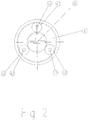
- the cutting discs 6, 7, 8; 15, 16 and 17 are made of Teflon and have a central opening 33 whose cross section corresponds to the cross section of the extruded profile to be treated. Depending on which type of extruded profile should therefore be treated in the treatment chamber, appropriate cutting discs are to be selected from a set of cutting discs.
- a T-shaped opening 33 is shown which is suitable for a T-shaped extruded profile.
- annular receptacles 34 which are connected with its outer edge gas-tight with the inner circumferential surface of the locks. The following is this in the Fig. 3 explained in more detail on the example of the near-cavity blade 6 in the entrance lock 5: Before the open center 35 of the annular receptacles 34, the cutting disc 6 is received gas-tight and fixed by means of a bayonet closure 36.
- the gas-tightness is achieved, in which the cutting disc 6 is applied against an elastically resilient sealing ring 37 of the receptacle 34.
- the elasticity of the sealing ring 37 ensures that a pressure on the closed Bayonet closure 36 is exercised so that it does not accidentally dissolves.
- Fig. 3 has to form the bayonet catch 36, the receptacle 34 in its side facing the cutting disk 6 at least three circumferential grooves 38, one of which is shown and which except for an input hole 39 of webs 40, which form a slot 41, are covered , so that undercuts are formed.
- the head 43 passes behind the webs 40 when the cutting disc 8 is rotated about its central axis.
- the mushrooms 42 which engage behind the webs 40 in the grooves 37, thus hold the cutting disk 8 gas-tight on the receptacle 34.
Landscapes
- Chemical & Material Sciences (AREA)
- Chemical Kinetics & Catalysis (AREA)
- Physics & Mathematics (AREA)
- Engineering & Computer Science (AREA)
- Plasma & Fusion (AREA)
- General Chemical & Material Sciences (AREA)
- Health & Medical Sciences (AREA)
- Medicinal Chemistry (AREA)
- Polymers & Plastics (AREA)
- Organic Chemistry (AREA)
- Treating Waste Gases (AREA)
- Processing And Handling Of Plastics And Other Materials For Molding In General (AREA)
Abstract
Description
- Die Erfindung bezieht sich auf eine Anlage zur kontinuierlichen Behandlung der Oberfläche eines aus einem Kunststoff bestehenden Strangprofils in einer mit einem Gas flutbaren Behandlungskammer, die einen Eingang zum Einführen des Profilstranges in die Behandlungskammer und einen Ausgang zum Ausführen des behandelten Strangprofils aus der Behandlungskammer aufweist.
- Eine derartige Anlage, die zur Fluorierung von Kunststoffbahnen genutzt wird, wird in der
EP 0214 635 A2 beschrieben. Mit einer Fluorierung werden die Oberflächenmoleküle eines Kunststoffsubstrats aktiviert, so dass eine Beschichtung des Substrats - z. B. ein Lack - besser auf seiner Oberfläche haftet. Zur Fluorierung wird in die Behandlungskammer ein Gas eingeleitet, das im Wesentlichen aus Stickstoff mit Anteilen von Sauerstoff und einem noch kleineren Anteil von Fluor besteht. Dabei besteht das generelle Problem, dass Fluor sehr reaktiv und sehr giftig ist, so dass die Anlage so eingerichtet sein muss, dass bei ihrem Betrieb möglichst kein oder allenfalls nur Spuren von Fluor in die Umgebung austritt. - Daher ist gemäß der
EP 0 214 635 A2 vorgesehen, dass sich vor und hinter der Behandlungskammer jeweils eine Schleuse befindet, die mit einem Inertgas geflutet wird. Außerdem sind im Eingang und Ausgang der Behandlungskammer jeweils zwei Walzen vorgesehen, die beidseitig dicht an der Bahn anliegen. - Diese Anordnung hat den Nachteil, dass sie nur für flache, bahnförmige Substrate eingesetzt werden kann. Es besteht aber die Notwendigkeit, die Behandlungskammer auch bei unregelmäßig geformten Profilsträngen abzudichten.
- Aus der
DE 10 2008 002 393 A1 ist eine ähnliche Anlage zur Behandlung von unregelmäßig geformten Profilsträngen bekannt. Demnach befindet sich im Ein- und Ausgang der Behandlungskammer jeweils ein Siphon, der mit einer Flüssigkeit gefüllt ist, die als Gasbarriere dient. Außerdem ist vor dem Eingangssiphon und hinter dem Ausgangssiphon jeweils ein Abzug vorgesehen, der mit einer Abgasreinigung verbunden ist, so dass Fluor, der durch die Siphons nach außen tritt, abgesaugt und in der Abgasreinigung gebunden werden kann. - Nachteilig bei dieser Anordnung ist es, dass der Profilstrang, damit er durch die Siphons laufen kann, mehrmals gebogen werden muss. Außerdem muss der Flüssigkeitsstand in den Siphons laufend überprüft werden, da bei einem nicht ausreichenden Flüssigkeitsstand in den Siphons Fluor in einer Menge aus der Behandlungskammer entweichen würde, die nicht sofort über die Auslässe abgezogen werden kann, und damit in die Umgebung gelangt.
- Die Erfindung beruht somit auf dem Problem, einen unregelmäßig geformten Profilstrang möglichst kontinuierlich und knickfrei durch eine mit einem Gas geflutete Behandlungskammer zu leiten, und dabei den Profilstrang mit einfachen Mitteln so zu dichten, dass kein oder nur wenig Gas die Behandlungskammer verlassen kann.
- Zur Lösung des Problems sieht die Erfindung vor, dass sowohl der Eingang als auch der Ausgang jeweils aus mindestens einer auswechselbaren Trennscheibe mit einer Öffnung für das Strangprofil besteht, wobei der Querschnitt der Öffnung dem Querschnitt des Strangprofils deckungsgleich entspricht.
- Deckungsgleich bedeutet in diesem Zusammenhang, dass die Querschnittsform der Öffnung und die des Strangprofils soweit übereinstimmen, dass der Rand der Trennscheibenöffnung möglichst nahe an den Umfang des Strangprofils heranreicht oder daran druckfrei anliegt, ohne dass zu hohe Reibungskräfte entstehen, die den Durchzug des Strangprofils durch die Anlage behindern würde.
- Mit einer solchen Anlage kann eine Vielzahl von unterschiedlichen Querschnitten behandelt werden. Dazu wird jeweils eine passende Trennscheibe eingesetzt, deren Öffnung möglichst vollständig von dem Querschnitt des zu behandelnden Strangprofils ausgefüllt wird.
- Trotz allem wird nicht zu vermeiden sein, dass durch den Spalt zwischen dem Strangprofil und dem Rand der Öffnung Fluor aus der Behandlungskammer austritt.
- Die Erfindung sieht daher weiterhin vor, dass der Eingang und/oder der Ausgang jeweils zwei auswechselbare Trennscheiben aufweist, die zwischen sich eine Schleusenkammer einer Eingangsschleuse und einer Ausgangsschleuse einschließen, die mit einem Absorber verbunden ist.
- Gas, was durch die innere Trennscheibe in die Schleusenkammer eintritt, wird durch die äußere Trennscheibe am weiteren Austritt in die Umgebung gehindert und zu einem Absorber abgesogen, der das Fluor bindet. Allenfalls minimalste Reste von Fluor können durch die jeweils äußeren Trennscheiben in die Umgebung austreten.
- Um die Trennscheiben auswechseln zu können, sind sie in Aufnahmen gasdicht aufgenommen, wobei die Aufnahmen selbst gasdicht in der Anlage angeordnet sind. Somit kann Gas allenfalls durch die Öffnungen in der Trennscheibe entweichen.
- Um ein Austauschen der Trennscheiben zu erleichtert, sind die Trennscheiben mittels eines Bajonettverschlusses in den Aufnahmen gehalten.
- Zur Lösung des Bajonettverschlusses werden die Trennscheibe und Ihre Mittelachse gedreht und dann der Aufnahme entnommen. Anschließend wird eine neue Trennscheibe in die Aufnahme eingesetzt und durch eine gegensinnige Drehung darin fixiert.
- Vorzugsweise sind die Aufnahmen in gegenüberliegenden Enden der Schleuse ausgebildet. Die Schleusen werden an die Behandlungskammer angeflanscht. Zum Auswechseln der Trennscheiben werden diese Flansche gelöst, so dass die Schleusen entnommen werden können. Dadurch ist ein Zugriff zu den Trennscheiben, die sich in den Enden der Schleusenkammer befinden, möglich.
- Um noch eine bessere Abdichtung der Behandlungskammer zu gewährleisten und einen noch größeren Anteil von Fluor aus dem aus der Behandlungskammer entwichenen Gas abzutrennen, ist vorgesehen, dass zumindest bei einer Schleuse zwischen den Trennscheiben an den Enden der Schleuse eine weitere Trennscheibe angeordnet ist, wodurch die Schleuse in zwei Zonen aufgeteilt ist, die jeweils einen Anschluss an einen Absorber haben.
- Die Schleusen stellen damit eine Art Kaskade dar. Der größte Teil des Fluors wird in der an die Behandlungskammer anschließende Zone abgesogen, ein kleiner Rest des Fluors, der durch die weitere Trennscheibe in die Zone, die weiter von der Behandlungskammer entfernt ist, eintritt, wird über den weiteren Absorber abgesogen.
- Damit die weitere Trennscheibe zwischen den beiden äußeren Trennscheiben für einen Austausch erreicht werden kann, hat sie einen etwas kleineren Durchmesser als die äußeren Trennscheiben, so dass sie durch die Aufnahmen für die äußeren Trennscheiben in die Schleusenkammer zu einer Aufnahme zwischen den beiden Zonen geführt werden kann.
- Um eine gleichmäßige Aktivierung des durch die Behandlungskammer fahrenden Profilstranges zu erreichen, ist vorgesehen, dass die Behandlungskammer einen Gaseinlass in Nähe des Ausganges und einen Gasauslass in der Nähe des Einganges aufweist, so dass die Behandlungskammer gegen die Bewegungsrichtung des Profilstranges vom Gas durchflutet wird.
- Frisches Gas mit einer höheren Konzentration an Fluor tritt somit am Ausgangsende der Behandlungskammer ein und ist daher in der Lage, die teilweise schon aktivierte Oberfläche weiter zu aktivieren. Am Eingang der Behandlungskammer reicht eine geringere Fluorgaskonzentration aus, da hier die Oberfläche noch nicht aktiviert ist und somit bereitwillig eine Aktivierung auch bei einer geringeren Fluorkonzentration zulässt.
- Die Umwälzung erfolgt mit einer Umwälzpumpe, die in einem Bypasskanal zwischen dem Gaseinlass und dem Gasauslass angeordnet ist.
- Im oder am Bypasskanal befindet sich auch ein Spektrometer, das laufend die Fluorgaskonzentration überwacht. Damit können dem Bypasskanal die Gase der Behandlungsatmosphäre, nämlich im Wesentlichen Stickstoff, Sauerstoff und Fluor, dosiert zugeleitet werden.
- Wie schon zuvor erwähnt, werden die Schleusenkammern von der Behandlungskammer entfernt, um die Trennscheiben auswechseln zu können. Dadurch wird die Behandlungskammer geöffnet. Um zuvor das Fluor aufweisende Gasgemisch daraus zu entfernen, ist an die Behandlungskammer eine Absaugkammer angeschlossen, die ebenfalls über einen Absorberanschluss verfügt, um das Fluor aus dem abgesaugten Gas entfernen zu können.
- Die Länge der Behandlungskammer, also der Abstand zwischen den Trennscheiben am Ein- und Ausgang, wird bestimmt von der benötigten Dauer der Fluoreinwirkung.
- Um bei einem großen Abstand den Trennscheiben am Ein- und Ausgang ein Durchhängen des Strangprofils in der Behandlungskammer zu vermeiden, können dort Laufstützen, z. B. in Form von Rollen, angeordnet werden.
- Im Folgenden soll anhand eines Ausführungsbeispiels die Erfindung näher erläutert werden. Dazu zeigt:
- Fig. 1
- einen Längsschnitt durch eine Anlage und
- Fig. 2
- eine Draufsicht auf eine Trennscheibe
- Fig. 3
- den Querschnitt einer Aufnahme mit einer Trennscheibe.
- Die Anlage gemäß der
Fig. 1 besteht aus mehreren Rohrabschnitten, die jeweils verschiedene Funktionen übernehmen. - Das mittlere Rohr bildet die Behandlungskammer 1, die an ihrem einen Ende in ein Zwischenrohr 2 übergeht, an dem sich ein Abzweig 3 zu einem Absorber 4 befindet. Davor liegt eine rohrförmige Eingangsschleuse 5 mit einer kammernahen, inneren Trennscheibe 6, einer kammerfernen, äußeren Trennscheibe 7 und einer dazwischenliegenden Zwischentrennscheibe 8. Auf diese Weise sind zwei Schleusenzonen 9 und 10 ausgebildet, die je über einen Außenanschluss 11, 12 mit einem Absorber verbunden sind.
- Auf der anderen Seite der Behandlungskammer, der Ausgangsseite, schließt sich ein optionales Verlängerungsrohr 13 an, das die Behandlungskammer verlängert und an das sich wiederum eine rohrförmige Ausgangsschleuse 14 anschließt. Diese Schleuse 14 ist mit einer kammernahen, inneren Trennscheibe 15, einer kammerfernen, äußeren Trennscheibe 16 und einer Zwischentrennscheibe 17 ausgestattet, so dass Schleusenzonen 18, 19 gebildet sind, die über je einen Absorber 4 verfügen. Bei den zuvor erwähnten Absorbern kann es sich um einen einzelnen, für alle Absorberanschlüsse gemeinsamen Absorber handeln oder aber auch um einzelne, unabhängig voneinander arbeitende Absorber.
- Die zuvor erwähnten Abschnitte der Anlage, also die Behandlungskammer 1, das Zwischenrohr 2, die Eingangsschleuse 5, das Verlängerungsrohr 13 und die Ausgangsschleuse 14 besitzen jeweils Flansche, mit denen sie zu einer durchgehenden linearen Strecke verbunden sind, die der Profilstrang knickfrei und kontinuierlich durchlaufen kann.
- Die Behandlungskammer 1 selbst verfügt über einen Gaseinlass 25 am Ausgangsende und einem Gasauslass 26 am Einlassende, die über einen Bypasskanal 27 miteinander verbunden sind. In diesem Kanal befindet sich eine Umwälzpumpe 28, so dass das am Gaseinlass eintretende Gas in Gegenrichtung zur Bewegung des Profilstranges zum Gasauslass 26 gepumpt wird. Stromaufwärts zur Umwälzpumpe befindet sich in dem Bypasskanal 27 ein Spektrometer 29, mit dessen Hilfe der Fluoranteil im Gas bestimmt wird.
- Vor und hinter dem Spektrometer 29 befinden sich Gaseinlässe 30, 31, über die mit Hilfe gesteuerter Ventile Gase eingelassen werden können, so dass das umgewälzte Gas einen Anteil von 1% Fluor hat, wobei die Restgasmenge sich zu 80% auf Stickstoff und zu 20% auf Sauerstoff verteilt.
- Die Trennscheiben 6, 7, 8; 15, 16 und 17 sind aus Teflon und besitzen eine zentrale Öffnung 33, deren Querschnitt dem Querschnitt des zu behandelnden Strangprofils entspricht. Je nachdem, welche Art von Strangprofil daher in der Behandlungskammer behandelt werden soll, sind entsprechende Trennscheiben aus einem Satz Trennscheiben auszuwählen.
- In der
Fig. 2 ist beispielhaft eine T-förmige Öffnung 33 dargestellt, die für ein T-förmiges Strangprofil geeignet ist. - In den Schleusenkammern der Eingangsschleuse 5 und der Ausgangsschleuse 14 befinden sich ringförmige Aufnahmen 34, die mit ihrem Außenrand gasdicht mit der inneren Mantelfläche der Schleusen verbunden sind. Im Folgenden wird dies in der
Fig. 3 am Beispiel der kammernahen Trennscheibe 6 in der Eingangsschleuse 5 näher erläutert:
Vor dem offenen Zentrum 35 der ringförmigen Aufnahmen 34 wird die Trennscheibe 6 gasdicht aufgenommen und mittels eines Bajonettverschlusses 36 fixiert. - Die Gasdichtigkeit wird erreicht, in dem die Trennscheibe 6 gegen einen elastisch nachgiebigen Dichtungsring 37 der Aufnahme 34 angelegt ist. Die Elastizität des Dichtungsringes 37 sorgt dafür, dass ein Druck auf den geschlossen Bajonettverschluss 36 ausgeübt wird, damit dieser sich nicht unbeabsichtigt löst.
- Wie der
Fig. 3 zu entnehmen ist, besitzt zur Ausbildung des Bajonettverschlusses 36 die Aufnahme 34 in ihrer der Trennscheibe 6 zugewandten Seite wenigstens drei umlaufende Nuten 38, von denen eine dargestellt ist und die bis auf ein Eingangsloch 39 von Stegen 40, die einen Schlitz 41 formen, abdeckt sind, so dass Hinterschnitte gebildet sind. In jedes Loch 39 taucht unter Zusammendrückung des Dichtungsringes 37 ein zugehöriger Pilz 42 an der Trennscheibe ein, dessen Kopf 43 hinter die Stege 40 gelangt, wenn die Trennscheibe 8 um ihre Mittelachse gedreht wird. Die Pilze 42, die die Stege 40 in den Nuten 37 hintergreifen, halten somit die Trennscheibe 8 gasdicht an der Aufnahme 34.Bezugszeichenliste 1 Behandlungskammer 26 Gasauslass 2 Zwischenrohr 27 Bypasskanal 3 Abzweig 28 Umwälzpumpe 4 Absorber 29 Spektrometer 5 Eingangsschleuse 30 Gaseinlass 6 kammernahe Trennscheibe 31 Gaseinlass 7 kammerferne Trennscheibe 32 8 Zwischentrennscheibe 33 Öffnung 9 Schleusenzone 34 ringförmige Aufnahmen 10 Schleusenzone 35 offenes Zentrum 11 Außenanschluss 36 Bajonettverschluss 12 Außenanschluss 37 Dichtungsring 13 Verlängerungsrohr 38 Nuten 14 Ausgangsschleuse 39 Eingangsloch 15 kammernahe Trennscheibe 40 Stege 16 kammerferne Trennscheibe 41 Schlitz 17 Zwischentrennscheibe 42 Pilz 18 Schleusenzone 43 Kopf 19 Schleusenzone 25 Gaseinlass
Claims (11)
- Anlage zur kontinuierlichen Behandlung der Oberfläche eines aus einem Kunststoff bestehenden Strangprofils in einer mit einem Gas flutbaren Behandlungskammer (1), die einen Eingang zum Einführen des Profilstranges in die Behandlungskammer (1) und einen Ausgang zum Ausführen des behandelten Strangprofils aus der Behandlungskammer (1) aufweist, dadurch gekennzeichnet, dass sowohl der Eingang als auch der Ausgang jeweils aus mindestens einer auswechselbaren Trennscheibe (6, 15) mit einer Öffnung (33) für das Strangprofil besteht, wobei der Querschnitt der Öffnung (33) dem Querschnitt des Strangprofils deckungsgleich entspricht.
- Anlage nach Anspruch 1, dadurch gekennzeichnet, dass der Eingang und/oder der Ausgang jeweils zwei auswechselbare Trennscheiben (6, 7; 15, 16) aufweist, die zwischen sich jeweils eine Schleusenkammer einer Eingangsschleuse (5) und einer Ausgangsschleuse (14) einschließen, die mit einem Absorber (4) verbunden ist.
- Anlage nach Anspruch 1 oder 2, dadurch gekennzeichnet, dass die Trennscheiben (6, 7; 15, 16) in Aufnahmen (34) gasdicht aufgenommen sind, wobei die Aufnahmen (34) gasdicht in der Anlage angeordnet sind.
- Anlage nach Anspruch 3, dadurch gekennzeichnet, dass die Trennscheiben (6, 7,15, 16) mittels eines Bajonettverschlusses (36) in den Aufnahmen (34) gehalten sind.
- Anlage nach Anspruch 3 oder 4, dadurch gekennzeichnet, dass die Aufnahmen (34) in gegenüberliegenden Enden der Schleusen (5, 14) ausgebildet sind.
- Anlage nach Anspruch 5, dadurch gekennzeichnet, dass zumindest eine der Schleusen (5, 14) eine weitere Trennscheibe (8, 17) aufweist, die zwischen den Trennscheiben (6, 7,15, 16) an den Enden der Schleuse (5, 14) angeordnet ist, wodurch die Schleuse in zwei Zonen (9, 10; 18, 19) aufgeteilt ist, die jeweils einen Anschluss an einen Absorber (4) haben.
- Anlage nach einem der vorhergehenden Ansprüche, dadurch gekennzeichnet, dass die Behandlungskammer (1) einen Gaseinlass (25) in der Nähe des Ausganges und einen Gasauslass (26) in der Nähe des Einganges aufweist, so dass die Behandlungskammer (1) gegen die Bewegungsrichtung des Profilstranges von dem Gas durchflutet wird.
- Anlage nach Anspruch 7, dadurch gekennzeichnet, dass eine Umwälzpumpe (28) in einem Bypasskanal (27) zwischen dem Gaseinlass (25) und dem Gasauslass (26) angeordnet ist.
- Anlage nach Anspruch 8, dadurch gekennzeichnet, dass im oder am Bypasskanal (27) ein Spektrometer (29) angeordnet ist.
- Anlage nach einem der vorhergehenden Ansprüche, dadurch gekennzeichnet, dass an die Behandlungskammer (1) eine Absaugkammer angeschlossen ist, die über einen Absorberanschluss verfügt.
- Anlage nach einem der vorhergehenden Ansprüche, dadurch gekennzeichnet, dass Laufstützen für den Profilstrang in der Behandlungskammer (1) angeordnet sind.
Applications Claiming Priority (1)
| Application Number | Priority Date | Filing Date | Title |
|---|---|---|---|
| DE102017112161.7A DE102017112161A1 (de) | 2017-06-01 | 2017-06-01 | Anlage zur kontinuierlichen Behandlung eines Strangprofils |
Publications (3)
| Publication Number | Publication Date |
|---|---|
| EP3409437A1 true EP3409437A1 (de) | 2018-12-05 |
| EP3409437C0 EP3409437C0 (de) | 2023-09-20 |
| EP3409437B1 EP3409437B1 (de) | 2023-09-20 |
Family
ID=62386143
Family Applications (1)
| Application Number | Title | Priority Date | Filing Date |
|---|---|---|---|
| EP18174357.6A Active EP3409437B1 (de) | 2017-06-01 | 2018-05-25 | Anlage zur kontinuierlichen behandlung eines strangprofils |
Country Status (2)
| Country | Link |
|---|---|
| EP (1) | EP3409437B1 (de) |
| DE (1) | DE102017112161A1 (de) |
Citations (4)
| Publication number | Priority date | Publication date | Assignee | Title |
|---|---|---|---|---|
| US3624806A (en) * | 1969-03-04 | 1971-11-30 | Hartmann As Brdr | Method of heat treating by convection objects, such as flat individual blanks, molded pulp articles or continuous webs or threads, for example for plastic fibers, and a kiln for use in the method |
| DE2838524A1 (de) * | 1978-09-04 | 1980-03-20 | Scholz Gmbh Co Kg Maschbau | Endabdichtung eines ein kabel aufnehmenden ringraumes |
| US4743419A (en) * | 1985-03-04 | 1988-05-10 | The Dow Chemical Company | On-line film fluorination method |
| DE4323790A1 (de) * | 1993-07-15 | 1995-01-19 | Ic Umwelt & Und Anlagentechnik | Verfahren und Vorrichtung zur kontinuierlichen Fluorierung von Kunststoffbahnen |
Family Cites Families (2)
| Publication number | Priority date | Publication date | Assignee | Title |
|---|---|---|---|---|
| DE3532086A1 (de) | 1985-09-09 | 1987-03-12 | Lohmann Gmbh & Co Kg | Verfahren zur oberflaechenbehandlung von flaechigem kunststoffmaterial |
| DE102008002393A1 (de) | 2008-06-12 | 2009-12-17 | Robert Bosch Gmbh | Vorrichtung zur Gasexposition |
-
2017
- 2017-06-01 DE DE102017112161.7A patent/DE102017112161A1/de active Pending
-
2018
- 2018-05-25 EP EP18174357.6A patent/EP3409437B1/de active Active
Patent Citations (4)
| Publication number | Priority date | Publication date | Assignee | Title |
|---|---|---|---|---|
| US3624806A (en) * | 1969-03-04 | 1971-11-30 | Hartmann As Brdr | Method of heat treating by convection objects, such as flat individual blanks, molded pulp articles or continuous webs or threads, for example for plastic fibers, and a kiln for use in the method |
| DE2838524A1 (de) * | 1978-09-04 | 1980-03-20 | Scholz Gmbh Co Kg Maschbau | Endabdichtung eines ein kabel aufnehmenden ringraumes |
| US4743419A (en) * | 1985-03-04 | 1988-05-10 | The Dow Chemical Company | On-line film fluorination method |
| DE4323790A1 (de) * | 1993-07-15 | 1995-01-19 | Ic Umwelt & Und Anlagentechnik | Verfahren und Vorrichtung zur kontinuierlichen Fluorierung von Kunststoffbahnen |
Also Published As
| Publication number | Publication date |
|---|---|
| DE102017112161A1 (de) | 2018-12-06 |
| EP3409437C0 (de) | 2023-09-20 |
| EP3409437B1 (de) | 2023-09-20 |
Similar Documents
| Publication | Publication Date | Title |
|---|---|---|
| DE4110127A1 (de) | Duesenbaugruppe zum verspruehen von fluessigkeiten | |
| EP0317706B1 (de) | Rauchgaskanal zur Behandlung eines Rauchgases | |
| DE102010024840A1 (de) | Trockner | |
| DE2013244B2 (de) | Luftzuführungseinrichtung zur Injektion von vorzugsweise kalter Ventilationsluft | |
| DE3402323A1 (de) | Verfahren zum herstellen eines wenigstens aus zwei scheiben bestehenden isolierglases | |
| DE102010014489B3 (de) | Transportgestell zum Fördern eines Gegenstandes durch eine Trocknungsanlage, Verfahren zum Trocknen einer Beschichtung auf einem Gegenstand und Verwendung eines Transportgestells hierzu | |
| DE102004001628A1 (de) | Vorrichtung zur Behandlung von Gegenständen mit mindestens einem temperierten, gerichteten Luftstrahl | |
| DE2723222C2 (de) | Vorrichtung zum Trocknen von Gegenständen | |
| DE1921016B1 (de) | Abdichtungseinrichtung an den Ein- und Austrittsstellen einer mit hoher Temperatur betriebenen Hochdruckkammer | |
| EP2063206B1 (de) | Vorrichtung zum Behandeln einer Substratbahn | |
| EP3409437B1 (de) | Anlage zur kontinuierlichen behandlung eines strangprofils | |
| EP3040149B1 (de) | Lötvorrichtung mit gasverteilung | |
| DE102007058159A1 (de) | Tülle zum Hindurchführen eines Kabels | |
| DE4235288A1 (de) | Schiebetürbeschlag | |
| DE10216220A1 (de) | Unterdruckventil | |
| DE3817972C2 (de) | ||
| DE2650485A1 (de) | Selbststeuernde ventilanordnung | |
| DE2236103C3 (de) | LuftauslaB für Lüftungsanlagen | |
| EP1090864B1 (de) | Behandlungsvorrichtung für Materialbahnen | |
| DE69105194T2 (de) | Abbeizvorrichtung mit Anwendung von korrodierender Flüssigkeit. | |
| EP2205347B1 (de) | Schleusenvorrichtung und verfahren zum öffnen der schleusenvorrichtung | |
| DE29620916U1 (de) | Rückschlagventil mit im wesentlichen rotationssymmetrischer Strömungsführung | |
| DE202023106517U1 (de) | Vorrichtung zur Reinigung eines Messerrings einer Messerringholzzerspanungsvorrichtung | |
| DE2120952A1 (de) | Kegelventil | |
| AT516949A4 (de) | Gleitelement zum verschiebbaren Lagern eines Vorhanges oder einer Plane |
Legal Events
| Date | Code | Title | Description |
|---|---|---|---|
| PUAI | Public reference made under article 153(3) epc to a published international application that has entered the european phase |
Free format text: ORIGINAL CODE: 0009012 |
|
| STAA | Information on the status of an ep patent application or granted ep patent |
Free format text: STATUS: THE APPLICATION HAS BEEN PUBLISHED |
|
| AK | Designated contracting states |
Kind code of ref document: A1 Designated state(s): AL AT BE BG CH CY CZ DE DK EE ES FI FR GB GR HR HU IE IS IT LI LT LU LV MC MK MT NL NO PL PT RO RS SE SI SK SM TR |
|
| AX | Request for extension of the european patent |
Extension state: BA ME |
|
| STAA | Information on the status of an ep patent application or granted ep patent |
Free format text: STATUS: REQUEST FOR EXAMINATION WAS MADE |
|
| 17P | Request for examination filed |
Effective date: 20190605 |
|
| RBV | Designated contracting states (corrected) |
Designated state(s): AL AT BE BG CH CY CZ DE DK EE ES FI FR GB GR HR HU IE IS IT LI LT LU LV MC MK MT NL NO PL PT RO RS SE SI SK SM TR |
|
| STAA | Information on the status of an ep patent application or granted ep patent |
Free format text: STATUS: EXAMINATION IS IN PROGRESS |
|
| 17Q | First examination report despatched |
Effective date: 20211001 |
|
| GRAP | Despatch of communication of intention to grant a patent |
Free format text: ORIGINAL CODE: EPIDOSNIGR1 |
|
| STAA | Information on the status of an ep patent application or granted ep patent |
Free format text: STATUS: GRANT OF PATENT IS INTENDED |
|
| INTG | Intention to grant announced |
Effective date: 20230417 |
|
| GRAS | Grant fee paid |
Free format text: ORIGINAL CODE: EPIDOSNIGR3 |
|
| GRAA | (expected) grant |
Free format text: ORIGINAL CODE: 0009210 |
|
| STAA | Information on the status of an ep patent application or granted ep patent |
Free format text: STATUS: THE PATENT HAS BEEN GRANTED |
|
| AK | Designated contracting states |
Kind code of ref document: B1 Designated state(s): AL AT BE BG CH CY CZ DE DK EE ES FI FR GB GR HR HU IE IS IT LI LT LU LV MC MK MT NL NO PL PT RO RS SE SI SK SM TR |
|
| REG | Reference to a national code |
Ref country code: GB Ref legal event code: FG4D Free format text: NOT ENGLISH |
|
| REG | Reference to a national code |
Ref country code: CH Ref legal event code: EP |
|
| REG | Reference to a national code |
Ref country code: DE Ref legal event code: R096 Ref document number: 502018013272 Country of ref document: DE |
|
| REG | Reference to a national code |
Ref country code: IE Ref legal event code: FG4D Free format text: LANGUAGE OF EP DOCUMENT: GERMAN |
|
| U01 | Request for unitary effect filed |
Effective date: 20231011 |
|
| U07 | Unitary effect registered |
Designated state(s): AT BE BG DE DK EE FI FR IT LT LU LV MT NL PT SE SI Effective date: 20231019 |
|
| PG25 | Lapsed in a contracting state [announced via postgrant information from national office to epo] |
Ref country code: GR Free format text: LAPSE BECAUSE OF FAILURE TO SUBMIT A TRANSLATION OF THE DESCRIPTION OR TO PAY THE FEE WITHIN THE PRESCRIBED TIME-LIMIT Effective date: 20231221 |
|
| PG25 | Lapsed in a contracting state [announced via postgrant information from national office to epo] |
Ref country code: RS Free format text: LAPSE BECAUSE OF FAILURE TO SUBMIT A TRANSLATION OF THE DESCRIPTION OR TO PAY THE FEE WITHIN THE PRESCRIBED TIME-LIMIT Effective date: 20230920 Ref country code: NO Free format text: LAPSE BECAUSE OF FAILURE TO SUBMIT A TRANSLATION OF THE DESCRIPTION OR TO PAY THE FEE WITHIN THE PRESCRIBED TIME-LIMIT Effective date: 20231220 Ref country code: HR Free format text: LAPSE BECAUSE OF FAILURE TO SUBMIT A TRANSLATION OF THE DESCRIPTION OR TO PAY THE FEE WITHIN THE PRESCRIBED TIME-LIMIT Effective date: 20230920 Ref country code: GR Free format text: LAPSE BECAUSE OF FAILURE TO SUBMIT A TRANSLATION OF THE DESCRIPTION OR TO PAY THE FEE WITHIN THE PRESCRIBED TIME-LIMIT Effective date: 20231221 |
|
| PG25 | Lapsed in a contracting state [announced via postgrant information from national office to epo] |
Ref country code: IS Free format text: LAPSE BECAUSE OF FAILURE TO SUBMIT A TRANSLATION OF THE DESCRIPTION OR TO PAY THE FEE WITHIN THE PRESCRIBED TIME-LIMIT Effective date: 20240120 |
|
| PG25 | Lapsed in a contracting state [announced via postgrant information from national office to epo] |
Ref country code: ES Free format text: LAPSE BECAUSE OF FAILURE TO SUBMIT A TRANSLATION OF THE DESCRIPTION OR TO PAY THE FEE WITHIN THE PRESCRIBED TIME-LIMIT Effective date: 20230920 |
|
| PG25 | Lapsed in a contracting state [announced via postgrant information from national office to epo] |
Ref country code: SM Free format text: LAPSE BECAUSE OF FAILURE TO SUBMIT A TRANSLATION OF THE DESCRIPTION OR TO PAY THE FEE WITHIN THE PRESCRIBED TIME-LIMIT Effective date: 20230920 Ref country code: RO Free format text: LAPSE BECAUSE OF FAILURE TO SUBMIT A TRANSLATION OF THE DESCRIPTION OR TO PAY THE FEE WITHIN THE PRESCRIBED TIME-LIMIT Effective date: 20230920 Ref country code: IS Free format text: LAPSE BECAUSE OF FAILURE TO SUBMIT A TRANSLATION OF THE DESCRIPTION OR TO PAY THE FEE WITHIN THE PRESCRIBED TIME-LIMIT Effective date: 20240120 Ref country code: ES Free format text: LAPSE BECAUSE OF FAILURE TO SUBMIT A TRANSLATION OF THE DESCRIPTION OR TO PAY THE FEE WITHIN THE PRESCRIBED TIME-LIMIT Effective date: 20230920 Ref country code: SK Free format text: LAPSE BECAUSE OF FAILURE TO SUBMIT A TRANSLATION OF THE DESCRIPTION OR TO PAY THE FEE WITHIN THE PRESCRIBED TIME-LIMIT Effective date: 20230920 |
|
| U20 | Renewal fee for the european patent with unitary effect paid |
Year of fee payment: 7 Effective date: 20240326 |
|
| PG25 | Lapsed in a contracting state [announced via postgrant information from national office to epo] |
Ref country code: PL Free format text: LAPSE BECAUSE OF FAILURE TO SUBMIT A TRANSLATION OF THE DESCRIPTION OR TO PAY THE FEE WITHIN THE PRESCRIBED TIME-LIMIT Effective date: 20230920 |
|
| REG | Reference to a national code |
Ref country code: DE Ref legal event code: R097 Ref document number: 502018013272 Country of ref document: DE |
|
| PGFP | Annual fee paid to national office [announced via postgrant information from national office to epo] |
Ref country code: CZ Payment date: 20240517 Year of fee payment: 7 |
|
| PLBE | No opposition filed within time limit |
Free format text: ORIGINAL CODE: 0009261 |
|
| STAA | Information on the status of an ep patent application or granted ep patent |
Free format text: STATUS: NO OPPOSITION FILED WITHIN TIME LIMIT |
|
| 26N | No opposition filed |
Effective date: 20240621 |
|
| REG | Reference to a national code |
Ref country code: CH Ref legal event code: PL |
|
| PG25 | Lapsed in a contracting state [announced via postgrant information from national office to epo] |
Ref country code: MC Free format text: LAPSE BECAUSE OF FAILURE TO SUBMIT A TRANSLATION OF THE DESCRIPTION OR TO PAY THE FEE WITHIN THE PRESCRIBED TIME-LIMIT Effective date: 20230920 |
|
| GBPC | Gb: european patent ceased through non-payment of renewal fee |
Effective date: 20240525 |
|
| PG25 | Lapsed in a contracting state [announced via postgrant information from national office to epo] |
Ref country code: MC Free format text: LAPSE BECAUSE OF FAILURE TO SUBMIT A TRANSLATION OF THE DESCRIPTION OR TO PAY THE FEE WITHIN THE PRESCRIBED TIME-LIMIT Effective date: 20230920 Ref country code: CH Free format text: LAPSE BECAUSE OF NON-PAYMENT OF DUE FEES Effective date: 20240531 |
|
| PG25 | Lapsed in a contracting state [announced via postgrant information from national office to epo] |
Ref country code: IE Free format text: LAPSE BECAUSE OF NON-PAYMENT OF DUE FEES Effective date: 20240525 |
|
| PG25 | Lapsed in a contracting state [announced via postgrant information from national office to epo] |
Ref country code: GB Free format text: LAPSE BECAUSE OF NON-PAYMENT OF DUE FEES Effective date: 20240525 |
|
| PG25 | Lapsed in a contracting state [announced via postgrant information from national office to epo] |
Ref country code: HU Free format text: LAPSE BECAUSE OF FAILURE TO SUBMIT A TRANSLATION OF THE DESCRIPTION OR TO PAY THE FEE WITHIN THE PRESCRIBED TIME-LIMIT; INVALID AB INITIO Effective date: 20180525 |
|
| PG25 | Lapsed in a contracting state [announced via postgrant information from national office to epo] |
Ref country code: CY Free format text: LAPSE BECAUSE OF FAILURE TO SUBMIT A TRANSLATION OF THE DESCRIPTION OR TO PAY THE FEE WITHIN THE PRESCRIBED TIME-LIMIT; INVALID AB INITIO Effective date: 20180525 |
|
| PG25 | Lapsed in a contracting state [announced via postgrant information from national office to epo] |
Ref country code: CZ Free format text: LAPSE BECAUSE OF NON-PAYMENT OF DUE FEES Effective date: 20250525 |
|
| U90 | Renewal fees not paid: noting of loss of rights |
Free format text: RENEWAL FEE NOT PAID FOR YEAR 08 Effective date: 20251219 |
|
| U93 | Unitary patent lapsed |
Free format text: RENEWAL FEE NOT PAID Effective date: 20250531 |
|
| PG25 | Lapsed in a contracting state [announced via postgrant information from national office to epo] |
Ref country code: TR Free format text: LAPSE BECAUSE OF FAILURE TO SUBMIT A TRANSLATION OF THE DESCRIPTION OR TO PAY THE FEE WITHIN THE PRESCRIBED TIME-LIMIT Effective date: 20230920 |