EP3408600B1 - Heat exchanger with tanks, tubes and retainer - Google Patents
Heat exchanger with tanks, tubes and retainer Download PDFInfo
- Publication number
- EP3408600B1 EP3408600B1 EP17744872.7A EP17744872A EP3408600B1 EP 3408600 B1 EP3408600 B1 EP 3408600B1 EP 17744872 A EP17744872 A EP 17744872A EP 3408600 B1 EP3408600 B1 EP 3408600B1
- Authority
- EP
- European Patent Office
- Prior art keywords
- tank
- aperture
- heat exchanger
- tube
- exchanger assembly
- Prior art date
- Legal status (The legal status is an assumption and is not a legal conclusion. Google has not performed a legal analysis and makes no representation as to the accuracy of the status listed.)
- Active
Links
- 229920001971 elastomer Polymers 0.000 claims 1
- 239000000806 elastomer Substances 0.000 claims 1
- 239000012530 fluid Substances 0.000 description 9
- 230000000712 assembly Effects 0.000 description 7
- 238000000429 assembly Methods 0.000 description 7
- 239000000463 material Substances 0.000 description 6
- 239000012809 cooling fluid Substances 0.000 description 3
- 238000005516 engineering process Methods 0.000 description 3
- 230000037431 insertion Effects 0.000 description 3
- 238000003780 insertion Methods 0.000 description 3
- 238000007789 sealing Methods 0.000 description 3
- 238000001816 cooling Methods 0.000 description 2
- -1 e.g. Substances 0.000 description 2
- 238000009434 installation Methods 0.000 description 2
- 238000004519 manufacturing process Methods 0.000 description 2
- 230000002093 peripheral effect Effects 0.000 description 2
- 239000004033 plastic Substances 0.000 description 2
- 238000006467 substitution reaction Methods 0.000 description 2
- OKTJSMMVPCPJKN-UHFFFAOYSA-N Carbon Chemical compound [C] OKTJSMMVPCPJKN-UHFFFAOYSA-N 0.000 description 1
- 239000004677 Nylon Substances 0.000 description 1
- 229910052782 aluminium Inorganic materials 0.000 description 1
- XAGFODPZIPBFFR-UHFFFAOYSA-N aluminium Chemical compound [Al] XAGFODPZIPBFFR-UHFFFAOYSA-N 0.000 description 1
- 230000002528 anti-freeze Effects 0.000 description 1
- 230000005540 biological transmission Effects 0.000 description 1
- 230000015556 catabolic process Effects 0.000 description 1
- 238000010276 construction Methods 0.000 description 1
- 239000002826 coolant Substances 0.000 description 1
- 238000006731 degradation reaction Methods 0.000 description 1
- 239000013536 elastomeric material Substances 0.000 description 1
- HQQADJVZYDDRJT-UHFFFAOYSA-N ethene;prop-1-ene Chemical group C=C.CC=C HQQADJVZYDDRJT-UHFFFAOYSA-N 0.000 description 1
- NBVXSUQYWXRMNV-UHFFFAOYSA-N fluoromethane Chemical compound FC NBVXSUQYWXRMNV-UHFFFAOYSA-N 0.000 description 1
- 239000007789 gas Substances 0.000 description 1
- 229910002804 graphite Inorganic materials 0.000 description 1
- 239000010439 graphite Substances 0.000 description 1
- 238000010438 heat treatment Methods 0.000 description 1
- 239000007788 liquid Substances 0.000 description 1
- 230000007774 longterm Effects 0.000 description 1
- 229910052751 metal Inorganic materials 0.000 description 1
- 239000002184 metal Substances 0.000 description 1
- 150000002825 nitriles Chemical class 0.000 description 1
- 229920001778 nylon Polymers 0.000 description 1
- 229920001296 polysiloxane Polymers 0.000 description 1
- XLYOFNOQVPJJNP-UHFFFAOYSA-N water Substances O XLYOFNOQVPJJNP-UHFFFAOYSA-N 0.000 description 1
Images


Classifications
-
- F—MECHANICAL ENGINEERING; LIGHTING; HEATING; WEAPONS; BLASTING
- F28—HEAT EXCHANGE IN GENERAL
- F28F—DETAILS OF HEAT-EXCHANGE AND HEAT-TRANSFER APPARATUS, OF GENERAL APPLICATION
- F28F9/00—Casings; Header boxes; Auxiliary supports for elements; Auxiliary members within casings
- F28F9/02—Header boxes; End plates
- F28F9/04—Arrangements for sealing elements into header boxes or end plates
- F28F9/06—Arrangements for sealing elements into header boxes or end plates by dismountable joints
-
- F—MECHANICAL ENGINEERING; LIGHTING; HEATING; WEAPONS; BLASTING
- F28—HEAT EXCHANGE IN GENERAL
- F28D—HEAT-EXCHANGE APPARATUS, NOT PROVIDED FOR IN ANOTHER SUBCLASS, IN WHICH THE HEAT-EXCHANGE MEDIA DO NOT COME INTO DIRECT CONTACT
- F28D1/00—Heat-exchange apparatus having stationary conduit assemblies for one heat-exchange medium only, the media being in contact with different sides of the conduit wall, in which the other heat-exchange medium is a large body of fluid, e.g. domestic or motor car radiators
- F28D1/02—Heat-exchange apparatus having stationary conduit assemblies for one heat-exchange medium only, the media being in contact with different sides of the conduit wall, in which the other heat-exchange medium is a large body of fluid, e.g. domestic or motor car radiators with heat-exchange conduits immersed in the body of fluid
- F28D1/04—Heat-exchange apparatus having stationary conduit assemblies for one heat-exchange medium only, the media being in contact with different sides of the conduit wall, in which the other heat-exchange medium is a large body of fluid, e.g. domestic or motor car radiators with heat-exchange conduits immersed in the body of fluid with tubular conduits
- F28D1/053—Heat-exchange apparatus having stationary conduit assemblies for one heat-exchange medium only, the media being in contact with different sides of the conduit wall, in which the other heat-exchange medium is a large body of fluid, e.g. domestic or motor car radiators with heat-exchange conduits immersed in the body of fluid with tubular conduits the conduits being straight
- F28D1/0535—Heat-exchange apparatus having stationary conduit assemblies for one heat-exchange medium only, the media being in contact with different sides of the conduit wall, in which the other heat-exchange medium is a large body of fluid, e.g. domestic or motor car radiators with heat-exchange conduits immersed in the body of fluid with tubular conduits the conduits being straight the conduits having a non-circular cross-section
- F28D1/05366—Assemblies of conduits connected to common headers, e.g. core type radiators
-
- F—MECHANICAL ENGINEERING; LIGHTING; HEATING; WEAPONS; BLASTING
- F28—HEAT EXCHANGE IN GENERAL
- F28D—HEAT-EXCHANGE APPARATUS, NOT PROVIDED FOR IN ANOTHER SUBCLASS, IN WHICH THE HEAT-EXCHANGE MEDIA DO NOT COME INTO DIRECT CONTACT
- F28D7/00—Heat-exchange apparatus having stationary tubular conduit assemblies for both heat-exchange media, the media being in contact with different sides of a conduit wall
- F28D7/0066—Multi-circuit heat-exchangers, e.g. integrating different heat exchange sections in the same unit or heat-exchangers for more than two fluids
-
- F—MECHANICAL ENGINEERING; LIGHTING; HEATING; WEAPONS; BLASTING
- F28—HEAT EXCHANGE IN GENERAL
- F28F—DETAILS OF HEAT-EXCHANGE AND HEAT-TRANSFER APPARATUS, OF GENERAL APPLICATION
- F28F9/00—Casings; Header boxes; Auxiliary supports for elements; Auxiliary members within casings
- F28F9/02—Header boxes; End plates
- F28F9/04—Arrangements for sealing elements into header boxes or end plates
-
- F—MECHANICAL ENGINEERING; LIGHTING; HEATING; WEAPONS; BLASTING
- F28—HEAT EXCHANGE IN GENERAL
- F28F—DETAILS OF HEAT-EXCHANGE AND HEAT-TRANSFER APPARATUS, OF GENERAL APPLICATION
- F28F2230/00—Sealing means
Definitions
- aspects of this invention relate generally to heat exchangers, and, in particular, to heat exchangers with tank and tube-and-fin assemblies, having improved tank construction and improved tube-to-tank sealing arrangements.
- Heat exchangers typically are formed of a plurality of tube-and-fin assemblies, which are mounted and interconnected to a pair of opposed tanks.
- a heating or cooling fluid e.g., oil, air, etc. flows from one tank into and through the tubes and then out through the second tank. Air is passed over the tubes and fins to add or remove heat from the fluid passing through the tubes.
- the heat exchanger must be able to withstand system operating pressures without leaking. Elastomeric seals, or seals of other materials, are sometimes used within the heat exchanger to provide suitable sealing between the tubes and the tanks.
- aspects of the present invention may be used to advantageously provide a heat exchanger having advantageous pressure capabilities and improved performance.
- a heat exchanger assembly in accordance with a first aspect, includes first and second tanks having tube side walls, reservoirs formed therein, and apertures extending through the tube side walls.
- a flow tube having a plurality of fins on an exterior surface thereof, a first end, and a second end, the first end being received in an aperture of the first tank.
- a first seal is positioned between the flow tube and the first aperture.
- a retainer is positioned between the flow tube and the first aperture and between the first seal and the fins on the tube.
- a mounting blocked is positioned between the first tank and the fins on the tube, and is secured to the first tank.
- a second seal is positioned between the flow tube and the second aperture.
- a heat exchanger assembly includes first and second tanks having tube side walls, reservoirs formed therein, and a plurality of apertures extending through the tube side walls.
- Each of a plurality of flow tubes has a plurality of fins on an exterior surface thereof, a first end, and a second end, the ends being received in a corresponding aperture of the first and second tanks.
- Each of a plurality of first seals is positioned between one of the flow tubes and an interior surface of a corresponding aperture in the first tank.
- Each of a plurality of retainers is positioned between one of the flow tubes and the interior surface of a corresponding aperture in the first tank and between the first seal and the fins on one of the flow tubes.
- Each of a plurality of mounting blocks is positioned between the first tank and the fins on the one of the flow tubes, and is secured to the first tank.
- Each of a plurality of second seals is positioned between one of the flow tubes and an interior surface of a corresponding aperture in the second tank.
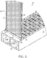
- FIG. 1 An embodiment of a heat exchanger 10 is shown in FIG. 1 , partially assembled and partially cut away, and is used to cool hot fluid, e.g., oil or air, generated in the use of industrial machinery, e.g., a hydraulic transmission, compressor, or turbocharger (not shown).
- hot fluid e.g., oil or air
- industrial machinery e.g., a hydraulic transmission, compressor, or turbocharger (not shown).
- heat exchanger 10 could be used in certain embodiments to heat a cool fluid.
- hot fluid would flow through the inside of heat exchanger 10, while a cooling fluid such as air or another suitable cooling fluid would contact the outside of heat exchanger 10 thereby cooling the hot fluid.
- the heat exchanger is not limited to use in cooling hot fluid in industrial machinery, and may easily be used with fluids or gases in other fields.
- embodiments of the present invention find application in heat exchangers such as radiators used to cool an engine where coolant, such as water or antifreeze, flows through flow tubes and fluid such as air or a suitable liquid can be used to flow around the exterior of flow tubes.
- coolant such as water or antifreeze
- fluid such as air or a suitable liquid can be used to flow around the exterior of flow tubes.
- the terms “upper” and “lower” and “top” and “bottom” are used herein to differentiate between the upper and lower ends of the heat exchanger and particular elements. It is to be appreciated that “upper” and “lower” and “top” and “bottom” are used only for ease of description and understanding and that they are not intended to limit the possible spatial orientations of the heat exchanger or its components during assembly or use.
- Heat exchanger 10 includes a first tank 12 having a first reservoir 14 formed therein.
- first tank 12 is a lower or bottom tank of heat exchanger 10.
- a second tank 16 having a second reservoir 18 formed therein is positioned opposite and spaced from first tank 12, and is referred to in the illustrated embodiment as an upper or top tank of heat exchanger 10.
- Each of a plurality of tube-and-fin assemblies 19 includes a flow tube 20, and a plurality of fin elements or fins 22 secured to an exterior surface of each flow tube 20.
- Flow tubes 20 extend between first tank 12 and second tank 16. Fins 22 may be welded or otherwise secured to the exterior of flow tubes 20. It is to be appreciated that heat exchanger 10 can have any desired number of tube-and-fin assemblies 19.
- a first or lower end 24 of each tube 20 is received in a first aperture 25 (seen in FIGS. 2 and 3 ) formed in first tank 12, as described in greater detail below.
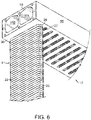
- a second or upper end 26 of each tube 20 is received in a second aperture 27 formed in second tank 16, as seen in FIG. 6 and described in greater detail below.
- First end 24 of tube 20 is secured within first tank 12 with a mounting block 28.
- Mounting block 28 is secured to first tank 12.
- mounting blocks 28 are secured to first tank 12 by way of fasteners, such as bolts 30 that are received in threaded recesses 32, seen in FIGS. 2 and 3 .
- fasteners such as bolts 30 that are received in threaded recesses 32, seen in FIGS. 2 and 3 .
- mounting block 28 can be secured to first tank 12 by other fasteners or any other fastening means.
- Other suitable fastening means will become readily apparent to those skilled in the art, given the benefit of this disclosure.
- Adjacent mounting blocks 28 are configured and mounted to first tank 12 such that they abut one another along sides thereof, which helps to keep them in position when they are subject to the large pressures often produced within such heat exchangers 10. Positioning mounting blocks 28 in abutting relationship provides a structural advantage for heat exchanger 10, since the mounting blocks include apertures extending therethrough, as described below, and providing multiple mounting blocks abutting one another provides strength to one another to help withstand the high operating pressures of the heat exchanger.
- tubes 20 is relatively short with respect to both the height of first and second tanks 12, 16, and the height of mounting block 28. It is to be appreciated that these proportions are not necessarily applicable for all applications, and that tubes 20 can have any desired length and, in fact, in many applications are significantly longer than the height of first and second tanks 12, 16 and the height of mounting block 28. Suitable lengths of tubes 20 will become readily apparent to those skilled in the art, given the benefit of this disclosure.
- first tank 12 includes a plurality of first apertures 25, each of which receives a corresponding first end 24 of a tube 20.
- tube 20 and first aperture 25, as well as second aperture 27 seen in FIG. 6 have a racetrack cross-sectional shape with a longitudinal axis L.
- tubes 20, first apertures 25, and second apertures 27, may have cross-sectional shapes other than the racetrack shaped tube shown in FIG. 2 . For example, they may have a circular or oval cross-section.
- Other suitable cross-sectional shapes for tubes 20, first apertures 25, and second apertures 27 will become readily apparent to those skilled in the art, given the benefit of this disclosure.
- first seal 34 is seated on first end 24 of tube 20.
- Tube 20 is then tilted along longitudinal axis L and first end 24 is inserted into first aperture 25 at this angle.
- the stepped opening of first aperture 25, described in greater detail below, allows for the angled insertion of tube 20 into first aperture 25.
- tube 20 is tilted at an angle ⁇ of between approximately 10° and approximately 15° with respect to the vertical.
- the term “approximately” is intended to mean “close to” or “about” a particular value, within the constraints of sensible, commercial engineering objectives; costs; manufacturing tolerances; and capabilities in the field of heat exchanger manufacture and use.
- Tube 20 is then tilted till it is oriented vertically as seen in FIG. 3 with first end 24 received in first aperture 25.
- first seal 34 is positioned above tube side 38 of first tank 12 and first aperture 25.
- first aperture 25 is beveled, or chamfered at an edge 36 thereof at tube side 38 of first tank 12, which allows for easier insertion of first end 24 of tube 20 into first aperture 25, as described in greater detail below.
- beveled edge 36 is beveled at an angle of approximately 45°.
- a first shoulder 40 extends inwardly from an interior surface of first aperture 25 at a position away from beveled edge 36 and closer to a tank side 42 of first tank 12. First shoulder 40 engages first seal 34 when first end 24 of tube 20 is inserted into first aperture 25, as described in greater detail below.
- second aperture 27 is also beveled, or chamfered at an edge 44 thereof at tube side 46 second tank 16, which allows for easier insertion of second end 26 of tube 20 into second aperture 27, as described in greater detail below.
- beveled edge 44 is beveled at an angle of approximately 45°.
- a channel, groove, or recess 48 is formed in the interior surface of second aperture 27 adjacent to beveled edge 44 and closer to a tank side 50 of second tank 16.
- a second seal 52 is seated in recess 48 and serves to provide a seal between second end 26 of tube 20 when tube 20 is inserted into second aperture 27.
- a second shoulder 54 extends inwardly from the interior surface of second aperture 27 at a position inwardly from recess 48 and closer to tank side 50 of second tank 16.
- second end 26 is then moved upwardly into second aperture 27 of second tank 16, as illustrated in FIG. 6 , until the uppermost fins 22 contact a tube side 36 of second tank 16.
- second seal 52 is positioned within recess 48 and compressed therein by tube 20.
- first end 24 of tube 20 is still seated within first aperture 25 of first tank 12.
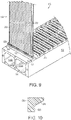
- retainer 56 is then positioned around first end 24 of tube 20 above first seal 34.
- retainer 56 has a racetrack shape like that of first seal 34, but is vertically split so that it can be expanded and slid onto the exterior of first end 24 of tube 20 above first seat 34. Retainer 56 can be seen fully seated around first end 24 of tube 20 in FIG. 9 .
- retainer 56 may have a shoulder 58 formed on a peripheral outer edge 60 of retainer 56.
- engagement surface 58 is formed as a shoulder that extends upwardly and outwardly at an angle from a central portion of peripheral outer edge 60. Shoulder 58 may engage with beveled edge 36 in first aperture 25 when first end 24 of tube 20 is inserted into first aperture 25. In certain embodiments, shoulder 58 extends at angle of approximately 45°. It is to be appreciated that in other embodiments retainer 56 has a rectangular cross-section.
- retainer 56 is formed of a plastic, such as a nylon plastic, for example. It is to be appreciated that retainer 56 could be formed of a metal, such as aluminum, for example. Other suitable materials for retainer 56 will become readily apparent to those skilled in the art, given the benefit of this disclosure.
- first end 24 is then pressed downwardly into first aperture 25.
- retainer 56 moves downwardly into first aperture 25, it pushes first seal 34 into first aperture 25 of first tank 12, as seen in FIGS. 11-12 .
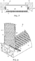
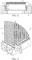
- a mounting block 62 is then slid into position adjacent tube 20 between the lower most fins 22 and first tank 12, as seen in FIG. 13 .
- a plurality of tubes 20 are shown with first ends 24 thereof inserted into corresponding first apertures 25 in first tank 12.
- the mounting block 62 seen here, which is being slid into position between adjacent tubes 20, is substantially T-shaped.
- the intersection between the arms 64 and the base 66 is curved so as to nest against the curved end of tube 20.
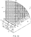
- Fig. 14 illustrates a plurality of T-shaped mounting blocks 62 in position, each seated between adjacent tubes 20.
- an endmost mounting block 62 which is positioned against an exterior surface of a single tube 20 is substantially L-shaped, with an intersection between a long arm 68 and a short arm 70 of the L-shape being curved so as to nest against the curved end of tube 20.
- the mounting blocks 62 are secured to first tank with bolts 30 that extend through apertures 72 formed in mounting blocks 62 and are threadingly received in recesses 32 in first tank 16, as seen in FIG. 1 .
- first seal 34 and second seal 52 are compressed a predetermined amount to provide a proper seal between the tube 20, first tank 12, and second tank 16.
- seals 34, 52 can have differing sizes and shapes.
- the seals could have a circular cross-section, such as those seals commonly known as "O-rings.”
- Other useful seals include those having a square or rectangular cross-section or a cross-section resembling that of an "X.”
- Other suitable seal shapes will become readily apparent to those skilled in the art, given the benefit of this disclosure, and the configuration of the elements within which the seal is seated.
- seals 34, 52 are fashioned from an elastomeric material.
- seals 34, 52 may be formed of fluorocarbon, silicone, nitrile, ethylene propylene, or fluorsilicone, for example.
- seals 34, 52 are formed of a material that is suitable for long term exposure to elevated temperatures, which may degrade elastomeric materials.
- a flexible graphite type material for example, may provide a long life span when exposed to elevated temperatures.
- Useful seals are capable of withstanding operating pressures and temperatures of a given heat exchanger, and are also resistant to degradation by fluids used in a given heat exchanger. The seals may be installed by hand or by suitable instrument so as to seat the seal into a given location.
- Other suitable materials used to form seals 34, 52 will become readily apparent to those skilled in the art, given the benefit of this disclosure.
Landscapes
- Engineering & Computer Science (AREA)
- Physics & Mathematics (AREA)
- Thermal Sciences (AREA)
- Mechanical Engineering (AREA)
- General Engineering & Computer Science (AREA)
- Heat-Exchange Devices With Radiators And Conduit Assemblies (AREA)
Applications Claiming Priority (2)
| Application Number | Priority Date | Filing Date | Title |
|---|---|---|---|
| US15/008,505 US10267576B2 (en) | 2016-01-28 | 2016-01-28 | Heat exchanger with tanks, tubes and retainer |
| PCT/US2017/015056 WO2017132328A1 (en) | 2016-01-28 | 2017-01-26 | Heat exchanger with tanks, tubes and retainer |
Publications (3)
| Publication Number | Publication Date |
|---|---|
| EP3408600A1 EP3408600A1 (en) | 2018-12-05 |
| EP3408600A4 EP3408600A4 (en) | 2019-07-24 |
| EP3408600B1 true EP3408600B1 (en) | 2022-06-08 |
Family
ID=59386513
Family Applications (1)
| Application Number | Title | Priority Date | Filing Date |
|---|---|---|---|
| EP17744872.7A Active EP3408600B1 (en) | 2016-01-28 | 2017-01-26 | Heat exchanger with tanks, tubes and retainer |
Country Status (11)
| Country | Link |
|---|---|
| US (2) | US10267576B2 (ja) |
| EP (1) | EP3408600B1 (ja) |
| JP (2) | JP6858194B2 (ja) |
| CN (1) | CN109312995B (ja) |
| AU (2) | AU2017212498B2 (ja) |
| BR (1) | BR112018015465B1 (ja) |
| CA (1) | CA3012677C (ja) |
| CL (1) | CL2018002022A1 (ja) |
| DK (1) | DK3408600T3 (ja) |
| MX (1) | MX2018009238A (ja) |
| WO (1) | WO2017132328A1 (ja) |
Families Citing this family (4)
| Publication number | Priority date | Publication date | Assignee | Title |
|---|---|---|---|---|
| CN109779733A (zh) * | 2017-11-14 | 2019-05-21 | 福特环球技术公司 | 具有经由可移动叶片的冷却剂路径的车辆散热器组件 |
| FR3077127B1 (fr) * | 2018-01-24 | 2020-05-22 | Valeo Systemes Thermiques | Echangeur thermique, notamment pour la regulation thermique de batteries |
| FR3107331B1 (fr) * | 2020-02-14 | 2022-02-18 | Tristone Flowtech Solutions Tfs | dispositif de circulation de fluide, son procédé de montage, ainsi qu’un ensemble comprenant un tel dispositif de circulation de fluide |
| EP3885689B1 (en) * | 2020-03-26 | 2023-10-25 | A. Raymond et Cie | Connector suitable to be connected to a multi port extruded tube |
Family Cites Families (48)
| Publication number | Priority date | Publication date | Assignee | Title |
|---|---|---|---|---|
| US1416337A (en) | 1920-11-01 | 1922-05-16 | Bernard P F Deane | Radiator for motor vehicles and the like |
| US1797524A (en) | 1925-10-29 | 1931-03-24 | C A Dunham Co | Radiator construction |
| US1886645A (en) | 1931-12-11 | 1932-11-08 | J H Mccormick & Co | Heating device |
| US2065515A (en) | 1934-12-19 | 1936-12-29 | American Radiator Co | Radiator |
| US2688986A (en) | 1950-09-02 | 1954-09-14 | Gen Motors Corp | Heat exchanger |
| US2677394A (en) | 1951-09-12 | 1954-05-04 | Young Radiator Co | Turbulence strip for heat exchanger tubes |
| US3391732A (en) | 1966-07-29 | 1968-07-09 | Mesabi Cores Inc | Radiator construction |
| US3527291A (en) | 1968-05-16 | 1970-09-08 | Aero Flow Dynamics Inc | Expansion accommodating means and method |
| FR2320520A1 (fr) | 1975-08-06 | 1977-03-04 | Ferodo Sa | Deflecteur pour tube d'echangeur de chaleur |
| US4236577A (en) | 1978-06-16 | 1980-12-02 | Mcquay-Perfex, Inc. | Separately removable tubes in heavy duty heat exchanger assemblies |
| US4344478A (en) | 1980-07-31 | 1982-08-17 | L & M Radiator, Inc. | Heat exchange apparatus |
| FR2492963B1 (fr) * | 1980-10-23 | 1986-01-31 | Chausson Usines Sa | Echangeur de chaleur a tubes et ailettes et a plaques collectrices assemblees mecaniquement |
| US4441547A (en) | 1981-01-05 | 1984-04-10 | Borg-Warner Corporation | Radiator mounting fittings |
| DE3311579C2 (de) | 1983-03-30 | 1985-10-03 | Süddeutsche Kühlerfabrik Julius Fr. Behr GmbH & Co. KG, 7000 Stuttgart | Wärmetauscher |
| JPS62213692A (ja) * | 1986-03-14 | 1987-09-19 | Matsushita Electric Works Ltd | 排熱ガスからの熱回収装置 |
| US4657069A (en) | 1986-03-31 | 1987-04-14 | Deere & Company | Heat exchange tube retainer |
| US4709689A (en) | 1986-12-02 | 1987-12-01 | Environmental Resources, Inc. | Solar heat exchange system |
| JPS63134285U (ja) * | 1987-02-23 | 1988-09-02 | ||
| US4727907A (en) | 1987-03-30 | 1988-03-01 | Dunham-Bush | Turbulator with integral flow deflector tabs |
| IT1231685B (it) | 1989-05-18 | 1991-12-19 | Giovanni Meirana | Attrezzatura per la saldatura di elementi di tubo in materiale plastico saldabili per fusione, procedimento di saldatura impiegante detta attrezzatura, raccordi di tubo impiegabili con detta attrezzatura e in detto procedimento e elementi di tubo cosi' ottenuti |
| US5062476A (en) * | 1991-02-28 | 1991-11-05 | General Motors Corporation | Heat exchanger with an extruded tank |
| JPH07151488A (ja) | 1993-11-29 | 1995-06-16 | Sanden Corp | 熱交換器及びその製造方法 |
| US5433268A (en) | 1993-12-03 | 1995-07-18 | L & M Radiator, Inc. | Radiator construction |
| JPH08327276A (ja) | 1995-05-30 | 1996-12-13 | Sanden Corp | 多管式熱交換器 |
| JP3627083B2 (ja) | 1996-10-15 | 2005-03-09 | 株式会社フジキン | 流体継手用リテーナ |
| US6161614A (en) | 1998-03-27 | 2000-12-19 | Karmazin Products Corporation | Aluminum header construction |
| US6964297B1 (en) | 1998-07-14 | 2005-11-15 | L & M Radiator, Inc. | Removable tube heat exchanger and header plate |
| JP2002174498A (ja) * | 2000-12-08 | 2002-06-21 | Mitsubishi Heavy Ind Ltd | 熱交換器 |
| AU2002358769A1 (en) | 2001-12-21 | 2003-07-09 | Behr Gmbh And Co. | Device for exchanging heat |
| KR100638490B1 (ko) | 2002-05-29 | 2006-10-25 | 한라공조주식회사 | 열교환기 |
| WO2004005827A1 (de) | 2002-07-05 | 2004-01-15 | Behr Gmbh & Co. Kg | Wärmeübertrager, insbesondere verdampfer für eine fahrzeugklimaanlage |
| CN1981176B (zh) | 2004-07-05 | 2010-06-16 | 昭和电工株式会社 | 换热器 |
| US20060022458A1 (en) * | 2004-07-27 | 2006-02-02 | Timothy Droste | Sealed fluid connector assembly |
| US8037929B2 (en) | 2004-12-16 | 2011-10-18 | Showa Denko K.K. | Evaporator |
| ATE498812T1 (de) | 2005-02-02 | 2011-03-15 | Carrier Corp | Wärmetauscher mit perforierter platte in endkammer |
| CA2652700C (en) * | 2006-05-19 | 2011-11-29 | Robert Janezich | Removable tube heat exchanger with retaining assembly |
| US7921905B2 (en) | 2006-06-29 | 2011-04-12 | Mahle International Gmbh | Plastic intercooler |
| US7810785B2 (en) | 2007-04-27 | 2010-10-12 | National Coupling Company, Inc. | Undersea hydraulic coupling with hydrostatic pressure energized metal seal |
| US20090095458A1 (en) | 2007-10-15 | 2009-04-16 | Halla Climate Control | Structure of header-tank for a heat exchanger |
| US20100147501A1 (en) | 2008-12-15 | 2010-06-17 | Delphi Technologies, Inc. | Curled manifold for evaporator |
| EP2567171A1 (en) * | 2010-05-06 | 2013-03-13 | HeatMatrix Group B.V. | Heat exchanger tube sheet, a heat exchanger and a method of manufacturing a heat exchanger tube sheet |
| WO2011151846A1 (en) * | 2010-05-31 | 2011-12-08 | Alberto Sacristani | Method for manufacturing a radiator element, radiator element and radiator |
| US9671181B2 (en) | 2011-09-30 | 2017-06-06 | L&M Radiator, Inc. | Heat exchanger with improved tank and tube construction |
| DE112014000778T5 (de) * | 2013-02-12 | 2015-10-22 | Dana Canada Corporation | Wärmetauscher mit selbstausrichtenden Anschlussstücken |
| JP6403040B2 (ja) | 2014-02-05 | 2018-10-10 | 川崎重工業株式会社 | 炭素繊維複合材製受熱タイルおよびその製造方法 |
| KR101478204B1 (ko) | 2014-03-20 | 2015-01-06 | 주식회사 세계종합태양에너지 | 태양열시스템을 이용한 유리온실 |
| EP2960609B1 (en) * | 2014-06-26 | 2022-10-05 | Valeo Autosystemy SP. Z.O.O. | Manifold, in particular for use in a cooler of a cooling system |
| CN204373487U (zh) * | 2014-12-16 | 2015-06-03 | 海德尔节能技术股份有限公司 | 一种换热器管板的管孔结构 |
-
2016
- 2016-01-28 US US15/008,505 patent/US10267576B2/en active Active
-
2017
- 2017-01-26 WO PCT/US2017/015056 patent/WO2017132328A1/en active Application Filing
- 2017-01-26 CN CN201780017525.8A patent/CN109312995B/zh active Active
- 2017-01-26 EP EP17744872.7A patent/EP3408600B1/en active Active
- 2017-01-26 MX MX2018009238A patent/MX2018009238A/es unknown
- 2017-01-26 BR BR112018015465-2A patent/BR112018015465B1/pt active IP Right Grant
- 2017-01-26 AU AU2017212498A patent/AU2017212498B2/en active Active
- 2017-01-26 JP JP2018539901A patent/JP6858194B2/ja active Active
- 2017-01-26 DK DK17744872.7T patent/DK3408600T3/da active
- 2017-01-26 CA CA3012677A patent/CA3012677C/en active Active
-
2018
- 2018-07-26 CL CL2018002022A patent/CL2018002022A1/es unknown
-
2019
- 2019-03-28 US US16/367,883 patent/US10731929B2/en active Active
-
2021
- 2021-03-19 JP JP2021046187A patent/JP7106703B2/ja active Active
-
2022
- 2022-08-31 AU AU2022224776A patent/AU2022224776A1/en active Pending
Also Published As
| Publication number | Publication date |
|---|---|
| EP3408600A1 (en) | 2018-12-05 |
| JP7106703B2 (ja) | 2022-07-26 |
| CN109312995B (zh) | 2020-12-15 |
| US10731929B2 (en) | 2020-08-04 |
| CN109312995A (zh) | 2019-02-05 |
| US20170219297A1 (en) | 2017-08-03 |
| AU2022224776A1 (en) | 2022-09-22 |
| JP2021099219A (ja) | 2021-07-01 |
| CA3012677C (en) | 2024-01-09 |
| CA3012677A1 (en) | 2017-08-03 |
| JP2019503467A (ja) | 2019-02-07 |
| DK3408600T3 (da) | 2022-07-04 |
| WO2017132328A1 (en) | 2017-08-03 |
| AU2017212498A1 (en) | 2018-08-16 |
| EP3408600A4 (en) | 2019-07-24 |
| JP6858194B2 (ja) | 2021-04-14 |
| BR112018015465B1 (pt) | 2022-04-26 |
| AU2017212498B2 (en) | 2022-06-02 |
| CL2018002022A1 (es) | 2018-10-26 |
| BR112018015465A2 (pt) | 2018-12-18 |
| US20190219343A1 (en) | 2019-07-18 |
| US10267576B2 (en) | 2019-04-23 |
| MX2018009238A (es) | 2019-02-07 |
Similar Documents
| Publication | Publication Date | Title |
|---|---|---|
| US10731929B2 (en) | Heat exchanger with tanks, tubes and retainer | |
| EP2019958B1 (en) | Tube heat exchanger with removable tubes and retaining assembly | |
| US9671181B2 (en) | Heat exchanger with improved tank and tube construction | |
| US10030918B2 (en) | Radiator tank fastening system | |
| JP5401476B2 (ja) | 複合材からなる熱交換器端部構造体 | |
| JP2020526731A (ja) | 熱交換器 | |
| US6964297B1 (en) | Removable tube heat exchanger and header plate | |
| US20200166280A1 (en) | Heat exchanger | |
| US10563558B2 (en) | Exhaust heat recovery unit | |
| US7992622B2 (en) | Oil cooler fitting assembly | |
| CN110770527B (zh) | 热传递装置 | |
| AU752128B2 (en) | Removable tube heat exchanger and header plate | |
| CN114341580A (zh) | 热交换器的箱结构 |
Legal Events
| Date | Code | Title | Description |
|---|---|---|---|
| STAA | Information on the status of an ep patent application or granted ep patent |
Free format text: STATUS: THE INTERNATIONAL PUBLICATION HAS BEEN MADE |
|
| PUAI | Public reference made under article 153(3) epc to a published international application that has entered the european phase |
Free format text: ORIGINAL CODE: 0009012 |
|
| STAA | Information on the status of an ep patent application or granted ep patent |
Free format text: STATUS: REQUEST FOR EXAMINATION WAS MADE |
|
| 17P | Request for examination filed |
Effective date: 20180820 |
|
| AK | Designated contracting states |
Kind code of ref document: A1 Designated state(s): AL AT BE BG CH CY CZ DE DK EE ES FI FR GB GR HR HU IE IS IT LI LT LU LV MC MK MT NL NO PL PT RO RS SE SI SK SM TR |
|
| AX | Request for extension of the european patent |
Extension state: BA ME |
|
| STAA | Information on the status of an ep patent application or granted ep patent |
Free format text: STATUS: REQUEST FOR EXAMINATION WAS MADE |
|
| DAV | Request for validation of the european patent (deleted) | ||
| DAX | Request for extension of the european patent (deleted) | ||
| A4 | Supplementary search report drawn up and despatched |
Effective date: 20190621 |
|
| RIC1 | Information provided on ipc code assigned before grant |
Ipc: F28F 9/04 20060101ALI20190614BHEP Ipc: F28D 1/053 20060101ALI20190614BHEP Ipc: F28F 9/06 20060101ALI20190614BHEP Ipc: F28F 3/10 20060101AFI20190614BHEP |
|
| GRAP | Despatch of communication of intention to grant a patent |
Free format text: ORIGINAL CODE: EPIDOSNIGR1 |
|
| STAA | Information on the status of an ep patent application or granted ep patent |
Free format text: STATUS: GRANT OF PATENT IS INTENDED |
|
| INTG | Intention to grant announced |
Effective date: 20220104 |
|
| GRAS | Grant fee paid |
Free format text: ORIGINAL CODE: EPIDOSNIGR3 |
|
| GRAA | (expected) grant |
Free format text: ORIGINAL CODE: 0009210 |
|
| STAA | Information on the status of an ep patent application or granted ep patent |
Free format text: STATUS: THE PATENT HAS BEEN GRANTED |
|
| AK | Designated contracting states |
Kind code of ref document: B1 Designated state(s): AL AT BE BG CH CY CZ DE DK EE ES FI FR GB GR HR HU IE IS IT LI LT LU LV MC MK MT NL NO PL PT RO RS SE SI SK SM TR |
|
| REG | Reference to a national code |
Ref country code: AT Ref legal event code: REF Ref document number: 1497208 Country of ref document: AT Kind code of ref document: T Effective date: 20220615 Ref country code: CH Ref legal event code: EP |
|
| REG | Reference to a national code |
Ref country code: DE Ref legal event code: R096 Ref document number: 602017058302 Country of ref document: DE |
|
| REG | Reference to a national code |
Ref country code: DK Ref legal event code: T3 Effective date: 20220629 |
|
| REG | Reference to a national code |
Ref country code: IE Ref legal event code: FG4D |
|
| REG | Reference to a national code |
Ref country code: SE Ref legal event code: TRGR |
|
| REG | Reference to a national code |
Ref country code: FI Ref legal event code: FGE |
|
| REG | Reference to a national code |
Ref country code: LT Ref legal event code: MG9D |
|
| REG | Reference to a national code |
Ref country code: NL Ref legal event code: MP Effective date: 20220608 |
|
| PG25 | Lapsed in a contracting state [announced via postgrant information from national office to epo] |
Ref country code: NO Free format text: LAPSE BECAUSE OF FAILURE TO SUBMIT A TRANSLATION OF THE DESCRIPTION OR TO PAY THE FEE WITHIN THE PRESCRIBED TIME-LIMIT Effective date: 20220908 Ref country code: LT Free format text: LAPSE BECAUSE OF FAILURE TO SUBMIT A TRANSLATION OF THE DESCRIPTION OR TO PAY THE FEE WITHIN THE PRESCRIBED TIME-LIMIT Effective date: 20220608 Ref country code: HR Free format text: LAPSE BECAUSE OF FAILURE TO SUBMIT A TRANSLATION OF THE DESCRIPTION OR TO PAY THE FEE WITHIN THE PRESCRIBED TIME-LIMIT Effective date: 20220608 Ref country code: GR Free format text: LAPSE BECAUSE OF FAILURE TO SUBMIT A TRANSLATION OF THE DESCRIPTION OR TO PAY THE FEE WITHIN THE PRESCRIBED TIME-LIMIT Effective date: 20220909 Ref country code: ES Free format text: LAPSE BECAUSE OF FAILURE TO SUBMIT A TRANSLATION OF THE DESCRIPTION OR TO PAY THE FEE WITHIN THE PRESCRIBED TIME-LIMIT Effective date: 20220608 Ref country code: BG Free format text: LAPSE BECAUSE OF FAILURE TO SUBMIT A TRANSLATION OF THE DESCRIPTION OR TO PAY THE FEE WITHIN THE PRESCRIBED TIME-LIMIT Effective date: 20220908 |
|
| REG | Reference to a national code |
Ref country code: AT Ref legal event code: MK05 Ref document number: 1497208 Country of ref document: AT Kind code of ref document: T Effective date: 20220608 |
|
| PG25 | Lapsed in a contracting state [announced via postgrant information from national office to epo] |
Ref country code: RS Free format text: LAPSE BECAUSE OF FAILURE TO SUBMIT A TRANSLATION OF THE DESCRIPTION OR TO PAY THE FEE WITHIN THE PRESCRIBED TIME-LIMIT Effective date: 20220608 Ref country code: LV Free format text: LAPSE BECAUSE OF FAILURE TO SUBMIT A TRANSLATION OF THE DESCRIPTION OR TO PAY THE FEE WITHIN THE PRESCRIBED TIME-LIMIT Effective date: 20220608 |
|
| PG25 | Lapsed in a contracting state [announced via postgrant information from national office to epo] |
Ref country code: NL Free format text: LAPSE BECAUSE OF FAILURE TO SUBMIT A TRANSLATION OF THE DESCRIPTION OR TO PAY THE FEE WITHIN THE PRESCRIBED TIME-LIMIT Effective date: 20220608 |
|
| PG25 | Lapsed in a contracting state [announced via postgrant information from national office to epo] |
Ref country code: SM Free format text: LAPSE BECAUSE OF FAILURE TO SUBMIT A TRANSLATION OF THE DESCRIPTION OR TO PAY THE FEE WITHIN THE PRESCRIBED TIME-LIMIT Effective date: 20220608 Ref country code: SK Free format text: LAPSE BECAUSE OF FAILURE TO SUBMIT A TRANSLATION OF THE DESCRIPTION OR TO PAY THE FEE WITHIN THE PRESCRIBED TIME-LIMIT Effective date: 20220608 Ref country code: RO Free format text: LAPSE BECAUSE OF FAILURE TO SUBMIT A TRANSLATION OF THE DESCRIPTION OR TO PAY THE FEE WITHIN THE PRESCRIBED TIME-LIMIT Effective date: 20220608 Ref country code: PT Free format text: LAPSE BECAUSE OF FAILURE TO SUBMIT A TRANSLATION OF THE DESCRIPTION OR TO PAY THE FEE WITHIN THE PRESCRIBED TIME-LIMIT Effective date: 20221010 Ref country code: EE Free format text: LAPSE BECAUSE OF FAILURE TO SUBMIT A TRANSLATION OF THE DESCRIPTION OR TO PAY THE FEE WITHIN THE PRESCRIBED TIME-LIMIT Effective date: 20220608 Ref country code: CZ Free format text: LAPSE BECAUSE OF FAILURE TO SUBMIT A TRANSLATION OF THE DESCRIPTION OR TO PAY THE FEE WITHIN THE PRESCRIBED TIME-LIMIT Effective date: 20220608 Ref country code: AT Free format text: LAPSE BECAUSE OF FAILURE TO SUBMIT A TRANSLATION OF THE DESCRIPTION OR TO PAY THE FEE WITHIN THE PRESCRIBED TIME-LIMIT Effective date: 20220608 |
|
| PG25 | Lapsed in a contracting state [announced via postgrant information from national office to epo] |
Ref country code: PL Free format text: LAPSE BECAUSE OF FAILURE TO SUBMIT A TRANSLATION OF THE DESCRIPTION OR TO PAY THE FEE WITHIN THE PRESCRIBED TIME-LIMIT Effective date: 20220608 Ref country code: IS Free format text: LAPSE BECAUSE OF FAILURE TO SUBMIT A TRANSLATION OF THE DESCRIPTION OR TO PAY THE FEE WITHIN THE PRESCRIBED TIME-LIMIT Effective date: 20221008 |
|
| REG | Reference to a national code |
Ref country code: DE Ref legal event code: R097 Ref document number: 602017058302 Country of ref document: DE |
|
| PG25 | Lapsed in a contracting state [announced via postgrant information from national office to epo] |
Ref country code: AL Free format text: LAPSE BECAUSE OF FAILURE TO SUBMIT A TRANSLATION OF THE DESCRIPTION OR TO PAY THE FEE WITHIN THE PRESCRIBED TIME-LIMIT Effective date: 20220608 |
|
| PLBE | No opposition filed within time limit |
Free format text: ORIGINAL CODE: 0009261 |
|
| STAA | Information on the status of an ep patent application or granted ep patent |
Free format text: STATUS: NO OPPOSITION FILED WITHIN TIME LIMIT |
|
| PGFP | Annual fee paid to national office [announced via postgrant information from national office to epo] |
Ref country code: DK Payment date: 20230127 Year of fee payment: 7 |
|
| 26N | No opposition filed |
Effective date: 20230310 |
|
| PG25 | Lapsed in a contracting state [announced via postgrant information from national office to epo] |
Ref country code: SI Free format text: LAPSE BECAUSE OF FAILURE TO SUBMIT A TRANSLATION OF THE DESCRIPTION OR TO PAY THE FEE WITHIN THE PRESCRIBED TIME-LIMIT Effective date: 20220608 |
|
| PGFP | Annual fee paid to national office [announced via postgrant information from national office to epo] |
Ref country code: SE Payment date: 20230127 Year of fee payment: 7 |
|
| P01 | Opt-out of the competence of the unified patent court (upc) registered |
Effective date: 20230526 |
|
| REG | Reference to a national code |
Ref country code: CH Ref legal event code: PL |
|
| PG25 | Lapsed in a contracting state [announced via postgrant information from national office to epo] |
Ref country code: LU Free format text: LAPSE BECAUSE OF NON-PAYMENT OF DUE FEES Effective date: 20230126 |
|
| REG | Reference to a national code |
Ref country code: BE Ref legal event code: MM Effective date: 20230131 |
|
| PG25 | Lapsed in a contracting state [announced via postgrant information from national office to epo] |
Ref country code: LI Free format text: LAPSE BECAUSE OF NON-PAYMENT OF DUE FEES Effective date: 20230131 Ref country code: CH Free format text: LAPSE BECAUSE OF NON-PAYMENT OF DUE FEES Effective date: 20230131 |
|
| PG25 | Lapsed in a contracting state [announced via postgrant information from national office to epo] |
Ref country code: FR Free format text: LAPSE BECAUSE OF NON-PAYMENT OF DUE FEES Effective date: 20230131 Ref country code: BE Free format text: LAPSE BECAUSE OF NON-PAYMENT OF DUE FEES Effective date: 20230131 |
|
| PG25 | Lapsed in a contracting state [announced via postgrant information from national office to epo] |
Ref country code: IT Free format text: LAPSE BECAUSE OF FAILURE TO SUBMIT A TRANSLATION OF THE DESCRIPTION OR TO PAY THE FEE WITHIN THE PRESCRIBED TIME-LIMIT Effective date: 20220608 Ref country code: IE Free format text: LAPSE BECAUSE OF NON-PAYMENT OF DUE FEES Effective date: 20230126 |
|
| PGFP | Annual fee paid to national office [announced via postgrant information from national office to epo] |
Ref country code: FI Payment date: 20240125 Year of fee payment: 8 Ref country code: DE Payment date: 20240129 Year of fee payment: 8 Ref country code: GB Payment date: 20240129 Year of fee payment: 8 |