EP3407444B1 - Mechanism for opening and closing the cover of a housing - Google Patents
Mechanism for opening and closing the cover of a housing Download PDFInfo
- Publication number
- EP3407444B1 EP3407444B1 EP17382295.8A EP17382295A EP3407444B1 EP 3407444 B1 EP3407444 B1 EP 3407444B1 EP 17382295 A EP17382295 A EP 17382295A EP 3407444 B1 EP3407444 B1 EP 3407444B1
- Authority
- EP
- European Patent Office
- Prior art keywords
- cover
- grooves
- groove
- guiding
- housing
- Prior art date
- Legal status (The legal status is an assumption and is not a legal conclusion. Google has not performed a legal analysis and makes no representation as to the accuracy of the status listed.)
- Active
Links
- 230000007246 mechanism Effects 0.000 title claims description 39
- 230000000712 assembly Effects 0.000 claims description 40
- 238000000429 assembly Methods 0.000 claims description 40
- 230000000087 stabilizing effect Effects 0.000 claims description 8
- 239000004033 plastic Substances 0.000 claims description 7
- 239000000463 material Substances 0.000 claims description 4
- 238000013016 damping Methods 0.000 description 4
- 230000002787 reinforcement Effects 0.000 description 4
- 230000000717 retained effect Effects 0.000 description 3
- 230000000903 blocking effect Effects 0.000 description 2
- 238000004140 cleaning Methods 0.000 description 2
- 239000011248 coating agent Substances 0.000 description 1
- 238000000576 coating method Methods 0.000 description 1
- 230000000295 complement effect Effects 0.000 description 1
- 238000009795 derivation Methods 0.000 description 1
- 239000006185 dispersion Substances 0.000 description 1
- 239000000428 dust Substances 0.000 description 1
- 238000000605 extraction Methods 0.000 description 1
- 239000003302 ferromagnetic material Substances 0.000 description 1
- 230000003116 impacting effect Effects 0.000 description 1
- 230000003993 interaction Effects 0.000 description 1
- 238000004519 manufacturing process Methods 0.000 description 1
Images


Classifications
-
- H—ELECTRICITY
- H02—GENERATION; CONVERSION OR DISTRIBUTION OF ELECTRIC POWER
- H02G—INSTALLATION OF ELECTRIC CABLES OR LINES, OR OF COMBINED OPTICAL AND ELECTRIC CABLES OR LINES
- H02G3/00—Installations of electric cables or lines or protective tubing therefor in or on buildings, equivalent structures or vehicles
- H02G3/02—Details
- H02G3/08—Distribution boxes; Connection or junction boxes
- H02G3/18—Distribution boxes; Connection or junction boxes providing line outlets
- H02G3/185—Floor outlets and access cups
-
- A—HUMAN NECESSITIES
- A47—FURNITURE; DOMESTIC ARTICLES OR APPLIANCES; COFFEE MILLS; SPICE MILLS; SUCTION CLEANERS IN GENERAL
- A47B—TABLES; DESKS; OFFICE FURNITURE; CABINETS; DRAWERS; GENERAL DETAILS OF FURNITURE
- A47B21/00—Tables or desks for office equipment, e.g. typewriters, keyboards
- A47B21/06—Tables or desks for office equipment, e.g. typewriters, keyboards characterised by means for holding, fastening or concealing cables
-
- E—FIXED CONSTRUCTIONS
- E05—LOCKS; KEYS; WINDOW OR DOOR FITTINGS; SAFES
- E05B—LOCKS; ACCESSORIES THEREFOR; HANDCUFFS
- E05B1/00—Knobs or handles for wings; Knobs, handles, or press buttons for locks or latches on wings
-
- H—ELECTRICITY
- H02—GENERATION; CONVERSION OR DISTRIBUTION OF ELECTRIC POWER
- H02G—INSTALLATION OF ELECTRIC CABLES OR LINES, OR OF COMBINED OPTICAL AND ELECTRIC CABLES OR LINES
- H02G3/00—Installations of electric cables or lines or protective tubing therefor in or on buildings, equivalent structures or vehicles
- H02G3/02—Details
- H02G3/08—Distribution boxes; Connection or junction boxes
- H02G3/18—Distribution boxes; Connection or junction boxes providing line outlets
-
- A—HUMAN NECESSITIES
- A47—FURNITURE; DOMESTIC ARTICLES OR APPLIANCES; COFFEE MILLS; SPICE MILLS; SUCTION CLEANERS IN GENERAL
- A47B—TABLES; DESKS; OFFICE FURNITURE; CABINETS; DRAWERS; GENERAL DETAILS OF FURNITURE
- A47B21/00—Tables or desks for office equipment, e.g. typewriters, keyboards
- A47B21/06—Tables or desks for office equipment, e.g. typewriters, keyboards characterised by means for holding, fastening or concealing cables
- A47B2021/066—Tables or desks for office equipment, e.g. typewriters, keyboards characterised by means for holding, fastening or concealing cables with power or communication connection interface
Definitions
- the present invention relates to a mechanism for opening and closing the cover of a housing specifically a connection housing embeddable in a table, wall, floor or similar, of the type where the cover is adapted to be lifted by two opposite sides to allow access to the inside by either one or the other side.
- the present invention seeks to provide a mechanism that is simple, which takes the minimum room of the housing, that allows a smooth operation and that is easy to manufacture.
- Known in the art are the mechanisms for opening and closing the cover of a connections housing, the housing being embeddable in a table and the cover being adapted to be lifted by two opposite sides to allow access to the connections by either one or the other side, the mechanism comprising the cover, two end bearing surfaces of two opposite ends being defined in the cover for leaning on two edges adjacent the housing.
- a mechanism disclosed therein is based either on two protrusions in each of the sides that lean on complementary grooves.
- the drawback of this solution is that it is not optimal for correctly guiding the cover when opening or closing it. It is easy that the cover is disassembled when opening or closing it.
- An objective of the present invention is to guarantee an efficient guiding of the cover, such that the user does not have to worry when opening it.
- ES 2 474 917 A1 Another mechanism disclosed in ES 2 474 917 A1 is based on pivoting arms, such that one end of the pivoting arm is fixed to the housing, while the other end bears a movable axis, thus allowing the cover to be opened from both sides.
- Other mechanisms are disclosed in DE 20 2016 003253 U1 and DE 101 51 449 A1 .
- One major aim of the present invention is providing a cover that is efficiently guided but that can also fully removed for accessing the housing, for example for cleaning it or change the connections.
- the present invention proposes a mechanism for opening and closing the cover of a housing, according to claim 1.
- the guiding assemblies can have more features, like the vertical grooves, the stabilizing means, while avoiding occupying room in the housing.
- the first and second grooves are extended at their lower end by a vertical groove which extends upwards and has its upper end opened such that the cover can be totally uncoupled from the guiding assemblies when the cover is moved upwards with a translation movement.
- This feature allows the cover to be lifted for entirely retiring it and comfortably accessing the inside of the housing for cleaning it, or arranging connections.
- the first and the second groove are closed in their upper end.
- the cover when operating the cover for opening it from a side, the cover will remain retained. If the cover has to be removed, then it has to be lifted parallel to the surface of the table, wall, floor or similar where the housing is embedded such that the protrusions will take the way of the vertical grooves instead of the arched ones, which are closed.
- the first groove is placed in the vicinity of the first axis and the second groove is placed in the vicinity of the second axis, the first groove being extended at his lower end by a vertical which extends upwards, the second groove being extended at his lower end by a vertical which extends upwards, the vertical grooves being distinct grooves.
- first groove and the second groove are joined in their lower ends, such that they are extended therefrom by a common vertical groove.
- the protrusions engaging the guiding grooves are far away the rotation axis, such that the protrusions can produce high moments with respect to the axis. Therefore, by arranging conveniently the forces between the protrusions and the grooves, it will be possible to smooth the movement of the cover.
- each assembly has two grooves centred in the first axis and two grooves centred in the second axis, two grooves extending through a common vertical groove, the other two grooves extending through distinct vertical grooves.
- the guiding is more effective, we can ensure that the cover is correctly retained by two sides and the central grooves can be used for providing a good damping of the cover's movement.
- At least one of the first protrusions comprises a wheel.
- each of the first protrusions of the guiding extensions comprises a wheel.
- the wheel has proved to be especially effective for damping the movement of the cover.
- the dampening can be controlled by selecting the material of the wheel, for example rubber, or by providing some viscosity in the axis of the wheel.
- the mechanism comprises an embeddable structure which defines the housing, the guiding assemblies being fixed to the embeddable structure, the embeddable structure being provided with the bearing surfaces.
- the mechanism comprises an embeddable structure which defines the housing, the guiding assemblies being part of the embeddable structure, forming at least part of two opposed minor walls of the housing.
- the mechanism can be fixed to a table, wall, floor or similar and in case the guiding assemblies need to be replaced, since they are the parts supporting more wear and higher efforts, they can be replaced without the need of replacing the whole structure.
- the embeddable structure comprises a frame.
- the frame provides an improved aesthetics to the mechanism.
- the frame is made in two separate parts, such that a discontinuous portion is defined, the opposite ends of the cover fitting in the discontinuous portion.
- the cover and the frame can be made flush, thereby improving the aesthetics.
- two accessing apertures are defined between the frame and the cover, such that cables can access the connections within the housing when the cover is in a lowest position.
- the mechanism can comprise further covers for these apertures, for examples spring biased, such that they ensure that the housing is closed when no cables goes through the apertures.
- these additional covers can have a brush, thereby allowing the cables to pass therethrough, but preventing at the same time the dust from entering the housing.
- the embeddable structure comprises plates adjacent the guiding assemblies for the attachment thereof, the plates comprising grooves adjacent to some of the grooves of the guiding assemblies.
- the grooves of the plates are wider than the grooves of the guiding assemblies.
- This feature allows protecting the guiding assemblies, which can be therefore made of plastic, because if the user pulls up the cover too strongly, therefore the protrusions, conveniently extended to reach the structure, will be retained by the structure therefore avoiding too much deformation of the guiding assemblies.
- the guiding assemblies are made of plastic material.
- the guiding extensions and the guiding assemblies comprise means for stabilizing the position of the cover in different positions.
- These means for stabilizing can be implemented with cavities along the groove in combination with a ball-spring set arranged in the protrusion. Another possibility is to provide a ferromagnetic material at the stabilized positions.
- the present invention relates to a mechanism M for opening and closing the cover 1 of a housing H.
- the housing will typically houses a data and/ or power sockets.
- the data power socket and the inner surface of the housing can be provided with mutually engaging features.
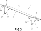
- the housing H is embeddable in a table, wall, floor or similar and the cover 1 is adapted to be lifted by two opposite sides 13, 14 to allow access to the connections by either one 13 or the other side 14, so that when one of the sides 13, 14 is lifted the other side 14, 13 remains fixed so that the cover pivots on one of a first E1 or a second E2 axes defined by the other side 14, 13 respectively, as shown in Figure 2 , 4 or 5 .
- the mechanism comprises the cover 1, where two end bearing surfaces S1, S2 of two opposite ends 11, 12 are defined for leaning on two edges B1, B2 adjacent the housing H, as shown for example in figure 8 .
- the edges B1 and B2 are placed in opposite locations with respect to the housing upper aperture and are adjacent the vertical minor walls of the housing H.
- the mechanism also comprises two guiding extensions P1, P2 extending from the cover 1 arranged adjacent the bearing surfaces S1, S2 and oriented towards the housing H.
- these guiding extensions are triangular.
- Two guiding assemblies G1, G2 are disposed on the housing surfaces adjacent to the edges B1, B2, so that the guiding assemblies G1, G2 face the guiding extension P1, P2, when the bearing surfaces S1, S2 of the cover leans on the two edges B1, B2.
- each guiding assembly G1, G2 comprises at least a first groove R1, R1' and a second groove R2, R2', both having a circular arc shape
- each guiding extension P1, P2 comprises at least a first protrusion W1, W2, U1, U2 that slides within the grooves R1, R1', R2, R2', wherein:
- the first R1, R1' and second R2, R2' grooves are extended at their lower end by a vertical groove R3, R3', R4, R4' which extends upwards and has its upper end opened such that the cover 1 can be totally uncoupled from the guiding assemblies G1, G2 when the cover 1 is moved upwards with a translation movement.
- the first R1, R1' and the second groove R2, R2' are closed in their upper end.
- the first groove R1' is placed in the vicinity of the first axis E1 and the second groove R2' is placed in the vicinity of the second axis E2, the first groove R1' being extended at his lower end by a vertical R3' which extends upwards, the second groove R2' being extended at his lower end by a vertical R4' which extends upwards, the vertical grooves being distinct grooves.
- the grooves have a short arched stroke, while the angle subtended defines the maximum opening angle of the cover 1.
- the part of the guiding extension P1, P2 which effectively guides, is close to the edges 13, 14, so the guiding extension P1, P2 comprises at the upper part on each opposite ends two protrusions U1, U2, that slide within the grooves R1, R1', R2, R2', whereas the central part of the guiding extension P1, P2, in this case the rounded triangle, comprises at its ends blocking means.
- first groove R1 and the second groove R2 are joined in their lower ends, such that they are extended therefrom by a common vertical groove R3, R4.
- This embodiment is advantageous in that the protrusions W1, W2 supported at the ends of the guiding extensions P1, P2 are far away from the cover rotation axis E1, E2 and therefore can exert a high moment with low forces. This is not the case for the embodiment shown in figure 8 , which in turn needs to be provided with the blocking means at the lowest end of the guiding extensions.
- each assembly has two grooves R1, R1' centred in the first axis E1 and two grooves R2, R2' centred in the second axis E2, two grooves R1, R2 extending through a common vertical groove R3, R4, the other two grooves R1', R2' extending through distinct vertical grooves R3', R4'.
- the guiding extension P1, P2 also comprises protrusions U1, U2 located at the upper part on each opposite end which are guided by the grooves R1', R2' which extends through distinct vertical grooves R3', R4', which preferably are in the vicinity of the rotation axis E1, E2 of the cover.
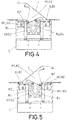
- the protrusions W1, W2 comprise each a wheel W, which is the arrangement shown in figures 3 to 7 .
- the damping force can be controlled by providing some energy dispersion means at the protrusion.
- the protrusion W1, W2 can be a simple pin or a ball-spring, which would provide some dampening thanks to the friction with the groove.
- this requires a high precision in the housing assembling, as the friction direction is the same as the direction of the gap between the guiding extensions P1, P2 and the guiding assemblies G1, G2.
- a wheel especially a plastic, elastic or rubber wheel allows for a smoother movement.
- the use of a wheel for dampening the closing of the cover 1 allows for changing the direction of the friction forces, from parallel to the gap longitude between the guiding extensions P1, P2 and the guiding assemblies G1, G2, to a perpendicular direction, which is executed between the longitudinal surface of the pin or a ball-spring or a coating of the same, and the wheel interior thickness surface and between the wheel external thickness surface and thickness surface of the grooves R1, R1', R2, R2' of the guiding assemblies G1, G2.
- This provides a greater degree of freedom in the assembling tolerances of the housing, as the contact surface providing friction is greater and the tolerance that need to be controlled is in the grooves R1, R1', R2, R2' wideness and its surface thickness.
- the protrusions U1, U2 located at the upper part on each opposite end of the guiding extension P1, P2 can be just a pin, a ball/ spring assembly, eventually in combination with a wheel, if additional dampening is considered necessary, achieving the advantages already mentioned in the previous paragraphs of changing the direction of the friction forces to allow a greater tolerance in the assembling of the housing.
- the guiding extension P1, P2 also comprises protrusions U1, U2 located at the upper part on each opposite end, which can be just a pin, a ball/ spring assembly, eventually in combination with a wheel, if additional dampening is considered necessary, achieving the advantages already mentioned in the previous paragraphs of changing the direction of the friction forces to allow a greater tolerance in the assembling of the housing.
- the housing H comprises an embeddable structure S which defines the housing H. Therefore, the guiding assemblies G1, G2 can be fixed to the embeddable structure S, the embeddable structure S being provided with the two edges of the housing B1, B2. Another possibility is that the guiding assemblies form an integral part of the embeddable structure S. In this case, as noted below, a reinforcement may be added to the upper edge of the grooves, for avoiding deformation or breaking of the guiding grooves when pulling the cover 1 too hard.
- the embeddable structure S also comprises a frame F preferably composed by two separate parts F1, F2, such that a discontinuous portion is defined, and the opposite ends 11, 12 of the cover 1 fitting in the discontinuous portion as shown in figure 1 . Then, two accessing apertures A1, A2 are defined between the frame F and the cover 1, such that cables can access the connections within the housing H when the cover 1 is in a lowest position.
- the frame is made of two frame parts F1, F2, that are flush with the upper cover surface in a closed condition. Therefore, the edges of the frame parts F1, F2 define, with respect to the two edges B1, B2 adjacent the housing (H) which are in a lower level, a step.
- the height of this step corresponds preferably to the thickness of the cover 1, and therefore the resulting upper surface comprising the cover and frame surface is flat.
- the steps defined between the levels between the frame F1, F2 surfaces and the two edges B1, B2 surface coincide with the first and second rotation axis E1, E2 of the cover, and help to stabilize the cover rotation.
- the embeddable structure S comprises plates H1, H2 adjacent the guiding assemblies G1, G2 for the attachment thereof, the plates H1, H2 comprising grooves H1R, H2R adjacent to some of the grooves R1, R1', R2, R2' of the guiding assemblies.
- the grooves of the plates H1, H2 are wider than the grooves R1, R1', R2, R2' of the guiding assemblies G1, G2.
- All the embodiments can comprise means for stabilizing the position of the cover 1 in some positions.
- such means are implemented by a cooperation between the guiding extensions P1, P2 and the guiding assemblies G1, G2.
- the means for stabilizing the position is a ball-spring which engages in cavities performed in the guiding assemblies G1, G2 surface or the plates of the embeddable structure.
- the stabilizing means are implemented by means of elastic tabs ET that cooperate with a protrusion at the end of the guiding extensions P1, P2 of the cover 1.
- the grooves R1, R1', R2, R2' of the guiding assemblies G1, G2 may comprise a plastic reinforcement not shown in the figures, which preferably will extend from the upper edge along the groove, and more preferably will extend from the upper curved edge where the arc groove R1, R1', R2, R2' extends into the straight groove R3, R3', R4, R4'. Otherwise said, if accidentally the cover 1 is pulled up too hard, the pins or guiding protrusions will abut on this reinforcements, thus ensuring the integrity of the guiding assemblies.
- the two grooves R1', R2' extending through distinct vertical grooves R3', R4' are wider than the diameter of the guiding protrusion, so a lack is provided between the guided protrusion and the groove that allows for an easier extraction of the cover and avoids tensions in the housing structure when opening the cover.
- These two grooves R1', R2' extending through distinct vertical grooves R3', R4' preferably comprises a plastic reinforcement extending from the upper curved edge where the arc groove R1', R2' extends into the straight groove R3', R4'.
- the guiding assemblies G1, G2 comprise a flexible appendage forming one of the walls of the straight grooves R3', R4'. Said appendage ends on its upper and free end on a bulged shape, as shown in figure 12 , so when the protrusion U1, U2, pass through the bulged end the appendage result displaced increasing the wide of the groove, therefore the unfitting of the cover is more difficult, avoiding to disassemble it accidentally and also providing a clip feeling to the user when the cover is disassembled and assembled in place.
- Another possibility, more robust, is to provide some cavities at the ends of the grooves, or at regular intervals, which cooperate with a ball biased with a spring towards the cavities.
- the inventive concept can be applied to other covers, not necessarily to covers for connections housing.
- it can be used for a housing embedded in a wall or for a closet. In these cases the cover would be contained in a vertical plane, like a door.
Landscapes
- Engineering & Computer Science (AREA)
- Architecture (AREA)
- Civil Engineering (AREA)
- Structural Engineering (AREA)
- Casings For Electric Apparatus (AREA)
- Closures For Containers (AREA)
- Legs For Furniture In General (AREA)
- Extensible Doors And Revolving Doors (AREA)
- Accommodation For Nursing Or Treatment Tables (AREA)
Priority Applications (5)
| Application Number | Priority Date | Filing Date | Title |
|---|---|---|---|
| ES17382295T ES2811316T3 (es) | 2017-05-23 | 2017-05-23 | Mecanismo para apertura y cierre de la tapa de una caja |
| EP17382295.8A EP3407444B1 (en) | 2017-05-23 | 2017-05-23 | Mechanism for opening and closing the cover of a housing |
| PL17382295T PL3407444T3 (pl) | 2017-05-23 | 2017-05-23 | Mechanizm otwierania i zamykania pokrywy obudowy |
| CN201810424852.1A CN108926117B (zh) | 2017-05-23 | 2018-05-07 | 用于打开和关闭壳体的盖子的机械装置 |
| RU2018118473A RU2759074C2 (ru) | 2017-05-23 | 2018-05-21 | Механизм открывания и закрывания крышки ниши |
Applications Claiming Priority (1)
| Application Number | Priority Date | Filing Date | Title |
|---|---|---|---|
| EP17382295.8A EP3407444B1 (en) | 2017-05-23 | 2017-05-23 | Mechanism for opening and closing the cover of a housing |
Publications (2)
| Publication Number | Publication Date |
|---|---|
| EP3407444A1 EP3407444A1 (en) | 2018-11-28 |
| EP3407444B1 true EP3407444B1 (en) | 2020-06-10 |
Family
ID=59091438
Family Applications (1)
| Application Number | Title | Priority Date | Filing Date |
|---|---|---|---|
| EP17382295.8A Active EP3407444B1 (en) | 2017-05-23 | 2017-05-23 | Mechanism for opening and closing the cover of a housing |
Country Status (5)
| Country | Link |
|---|---|
| EP (1) | EP3407444B1 (es) |
| CN (1) | CN108926117B (es) |
| ES (1) | ES2811316T3 (es) |
| PL (1) | PL3407444T3 (es) |
| RU (1) | RU2759074C2 (es) |
Families Citing this family (1)
| Publication number | Priority date | Publication date | Assignee | Title |
|---|---|---|---|---|
| EP4246745A1 (de) * | 2022-03-15 | 2023-09-20 | Tehalit GmbH | Leitungsauslass |
Family Cites Families (22)
| Publication number | Priority date | Publication date | Assignee | Title |
|---|---|---|---|---|
| US5575668A (en) * | 1995-10-06 | 1996-11-19 | Timmerman; Paul | Temporary power/data tap |
| CA2263062C (en) * | 1998-12-03 | 2006-04-11 | Gordon S. Almond | Flush mounted flip top telecommunication and electrical station for board room tables |
| DE10151449B4 (de) * | 2001-10-18 | 2007-09-13 | Aco Severin Ahlmann Gmbh & Co. Kg | Abdeckungsanordnung |
| US7578243B2 (en) * | 2005-04-07 | 2009-08-25 | Krueger International, Inc. | Laptop computer bin assembly for a worksurface |
| RU63126U1 (ru) * | 2006-12-19 | 2007-05-10 | Мария Владимировна Чеклецова | Люк для подвода кабелей |
| CN201073095Y (zh) * | 2007-07-20 | 2008-06-18 | 蔡杲 | 一种可用于隐藏引出线及放置小物品的通用盒 |
| JP5235377B2 (ja) * | 2007-10-12 | 2013-07-10 | 株式会社内田洋行 | 組み立てデスク、および組み立てデスクの集合体 |
| CN201340994Y (zh) * | 2008-12-12 | 2009-11-04 | 刘振福 | 一种压盖式线槽 |
| SE533693C2 (sv) * | 2009-04-20 | 2010-12-07 | Schneider Electric Ind Sas | Bordsbox infälld i bordskiva med anslutningar för el-, tele- och datauttag |
| CN201431127Y (zh) * | 2009-05-05 | 2010-03-31 | 东莞市冠辉五金有限公司 | 电线穿越装置 |
| CN201509844U (zh) * | 2009-09-15 | 2010-06-23 | 浙江大学 | 组合式多功能办公桌 |
| FR2968141B1 (fr) * | 2010-11-29 | 2012-12-28 | Legrand France | Appareillage electrique a support d'appareillage basculant |
| JP5673096B2 (ja) * | 2010-12-28 | 2015-02-18 | ソニー株式会社 | 機器開閉機構および情報機器 |
| CN202231382U (zh) * | 2011-09-23 | 2012-05-23 | 诺梵(上海)办公系统有限公司 | 办公桌用双翻线盒 |
| ES2427022B1 (es) * | 2012-04-25 | 2014-09-19 | Simón, S. A. | Soporte para dispositivos eléctricos |
| FR3000308B1 (fr) * | 2012-12-20 | 2015-01-09 | Legrand France | Module d'appareillage electrique amovible, boite electrique d'accueil d'un tel module d'appareillage et procede de remplacement d'un tel module d'appareillage |
| ES2474917B1 (es) | 2013-10-31 | 2015-04-13 | Simon, S.A.U. | Alojamiento para dispositivos eléctricos empotrable |
| CN104328966B (zh) * | 2013-11-29 | 2016-11-16 | 海尔集团公司 | 双向开门装置及具有该装置的冰箱 |
| CN104720303A (zh) * | 2013-12-19 | 2015-06-24 | 西安美育信息科技有限公司 | 一种带有分线槽的简洁易安装台式机电脑办公一体桌 |
| CN204015540U (zh) * | 2014-07-04 | 2014-12-17 | 广东优派家私集团有限公司 | 一种新型翻转线盒 |
| CN204179590U (zh) * | 2014-11-13 | 2015-02-25 | 震旦(中国)有限公司 | 带双面翻转盖板的走线盒以及具有该走线槽的桌子 |
| DE202016003253U1 (de) * | 2016-05-20 | 2016-07-13 | Sedus Stoll Aktiengesellschaft | Funktionsmöbel mit Medienklappenvorrichtung |
-
2017
- 2017-05-23 EP EP17382295.8A patent/EP3407444B1/en active Active
- 2017-05-23 PL PL17382295T patent/PL3407444T3/pl unknown
- 2017-05-23 ES ES17382295T patent/ES2811316T3/es active Active
-
2018
- 2018-05-07 CN CN201810424852.1A patent/CN108926117B/zh not_active Expired - Fee Related
- 2018-05-21 RU RU2018118473A patent/RU2759074C2/ru active
Non-Patent Citations (1)
| Title |
|---|
| None * |
Also Published As
| Publication number | Publication date |
|---|---|
| EP3407444A1 (en) | 2018-11-28 |
| PL3407444T3 (pl) | 2021-01-11 |
| RU2759074C2 (ru) | 2021-11-09 |
| RU2018118473A (ru) | 2019-11-22 |
| ES2811316T3 (es) | 2021-03-11 |
| RU2018118473A3 (es) | 2021-09-22 |
| CN108926117A (zh) | 2018-12-04 |
| CN108926117B (zh) | 2021-04-20 |
Similar Documents
| Publication | Publication Date | Title |
|---|---|---|
| EP2549042A1 (en) | Slide assist device | |
| JP4509182B2 (ja) | スライド型携帯電話用のスライダー組立体及びスライド型携帯電話 | |
| US9139043B1 (en) | Central-controlled double wheel structure | |
| JP5602838B2 (ja) | 自動閉鎖装置が設置された下部装着型スライド装置 | |
| EP3786400A1 (en) | Door closer and refrigerator comprising same | |
| EP3407444B1 (en) | Mechanism for opening and closing the cover of a housing | |
| KR101559676B1 (ko) | 댐퍼수납부가 확장된 슬라이더 완충장치 | |
| CN109477350A (zh) | 锁止装置 | |
| EP2336689A2 (en) | Door handle for a domestic refrigeration appliance | |
| KR20200048196A (ko) | 차량용 충전 포트 커버의 슬라이드 가이드 구조 | |
| KR20090053086A (ko) | 창호 설치형 환기장치 | |
| KR100904033B1 (ko) | 도어락 | |
| KR20110026835A (ko) | 로울러식 방충망의 잠금장치 및 이를 포함하는 로울러식 방충망 조립체 | |
| KR20210003403A (ko) | 안전문 | |
| EP2803787A2 (en) | Door closer arrangement | |
| KR102469188B1 (ko) | 안전경첩 | |
| EP4174421A1 (en) | Refrigerator door with replaceable door face | |
| CN210530569U (zh) | 一种阻尼器承载座及缓冲铰链 | |
| CN210342931U (zh) | 锁芯盖组件及智能门锁 | |
| KR200346618Y1 (ko) | 슬라이드 타입 휴대용 단말기 | |
| CN210530576U (zh) | 一种缓冲铰链 | |
| KR101929683B1 (ko) | 창호잠금장치용 키퍼 | |
| CN111719976A (zh) | 一种阻尼器承载座及缓冲铰链 | |
| KR200387217Y1 (ko) | 영구자석을 포함하는 슬라이딩 타입 휴대폰용 슬라이더조립체 및 그러한 슬라이더 조립체를 구비한 슬라이딩 타입휴대폰 | |
| CN219754301U (zh) | 一种智能锁 |
Legal Events
| Date | Code | Title | Description |
|---|---|---|---|
| PUAI | Public reference made under article 153(3) epc to a published international application that has entered the european phase |
Free format text: ORIGINAL CODE: 0009012 |
|
| STAA | Information on the status of an ep patent application or granted ep patent |
Free format text: STATUS: THE APPLICATION HAS BEEN PUBLISHED |
|
| AK | Designated contracting states |
Kind code of ref document: A1 Designated state(s): AL AT BE BG CH CY CZ DE DK EE ES FI FR GB GR HR HU IE IS IT LI LT LU LV MC MK MT NL NO PL PT RO RS SE SI SK SM TR |
|
| AX | Request for extension of the european patent |
Extension state: BA ME |
|
| STAA | Information on the status of an ep patent application or granted ep patent |
Free format text: STATUS: REQUEST FOR EXAMINATION WAS MADE |
|
| 17P | Request for examination filed |
Effective date: 20190211 |
|
| RAV | Requested validation state of the european patent: fee paid |
Extension state: MA Effective date: 20190211 |
|
| RBV | Designated contracting states (corrected) |
Designated state(s): AL AT BE BG CH CY CZ DE DK EE ES FI FR GB GR HR HU IE IS IT LI LT LU LV MC MK MT NL NO PL PT RO RS SE SI SK SM TR |
|
| GRAP | Despatch of communication of intention to grant a patent |
Free format text: ORIGINAL CODE: EPIDOSNIGR1 |
|
| STAA | Information on the status of an ep patent application or granted ep patent |
Free format text: STATUS: GRANT OF PATENT IS INTENDED |
|
| INTG | Intention to grant announced |
Effective date: 20190710 |
|
| GRAJ | Information related to disapproval of communication of intention to grant by the applicant or resumption of examination proceedings by the epo deleted |
Free format text: ORIGINAL CODE: EPIDOSDIGR1 |
|
| STAA | Information on the status of an ep patent application or granted ep patent |
Free format text: STATUS: REQUEST FOR EXAMINATION WAS MADE |
|
| GRAP | Despatch of communication of intention to grant a patent |
Free format text: ORIGINAL CODE: EPIDOSNIGR1 |
|
| STAA | Information on the status of an ep patent application or granted ep patent |
Free format text: STATUS: GRANT OF PATENT IS INTENDED |
|
| INTC | Intention to grant announced (deleted) | ||
| INTG | Intention to grant announced |
Effective date: 20191127 |
|
| GRAS | Grant fee paid |
Free format text: ORIGINAL CODE: EPIDOSNIGR3 |
|
| GRAJ | Information related to disapproval of communication of intention to grant by the applicant or resumption of examination proceedings by the epo deleted |
Free format text: ORIGINAL CODE: EPIDOSDIGR1 |
|
| GRAL | Information related to payment of fee for publishing/printing deleted |
Free format text: ORIGINAL CODE: EPIDOSDIGR3 |
|
| STAA | Information on the status of an ep patent application or granted ep patent |
Free format text: STATUS: REQUEST FOR EXAMINATION WAS MADE |
|
| GRAP | Despatch of communication of intention to grant a patent |
Free format text: ORIGINAL CODE: EPIDOSNIGR1 |
|
| STAA | Information on the status of an ep patent application or granted ep patent |
Free format text: STATUS: GRANT OF PATENT IS INTENDED |
|
| INTC | Intention to grant announced (deleted) | ||
| GRAS | Grant fee paid |
Free format text: ORIGINAL CODE: EPIDOSNIGR3 |
|
| GRAA | (expected) grant |
Free format text: ORIGINAL CODE: 0009210 |
|
| STAA | Information on the status of an ep patent application or granted ep patent |
Free format text: STATUS: THE PATENT HAS BEEN GRANTED |
|
| INTG | Intention to grant announced |
Effective date: 20200415 |
|
| AK | Designated contracting states |
Kind code of ref document: B1 Designated state(s): AL AT BE BG CH CY CZ DE DK EE ES FI FR GB GR HR HU IE IS IT LI LT LU LV MC MK MT NL NO PL PT RO RS SE SI SK SM TR |
|
| REG | Reference to a national code |
Ref country code: GB Ref legal event code: FG4D |
|
| REG | Reference to a national code |
Ref country code: CH Ref legal event code: EP Ref country code: AT Ref legal event code: REF Ref document number: 1279933 Country of ref document: AT Kind code of ref document: T Effective date: 20200615 |
|
| REG | Reference to a national code |
Ref country code: DE Ref legal event code: R096 Ref document number: 602017017949 Country of ref document: DE |
|
| REG | Reference to a national code |
Ref country code: IE Ref legal event code: FG4D |
|
| REG | Reference to a national code |
Ref country code: MA Ref legal event code: VAGR Ref document number: 44960 Country of ref document: MA Kind code of ref document: B1 |
|
| REG | Reference to a national code |
Ref country code: LT Ref legal event code: MG4D |
|
| PG25 | Lapsed in a contracting state [announced via postgrant information from national office to epo] |
Ref country code: SE Free format text: LAPSE BECAUSE OF FAILURE TO SUBMIT A TRANSLATION OF THE DESCRIPTION OR TO PAY THE FEE WITHIN THE PRESCRIBED TIME-LIMIT Effective date: 20200610 Ref country code: FI Free format text: LAPSE BECAUSE OF FAILURE TO SUBMIT A TRANSLATION OF THE DESCRIPTION OR TO PAY THE FEE WITHIN THE PRESCRIBED TIME-LIMIT Effective date: 20200610 Ref country code: LT Free format text: LAPSE BECAUSE OF FAILURE TO SUBMIT A TRANSLATION OF THE DESCRIPTION OR TO PAY THE FEE WITHIN THE PRESCRIBED TIME-LIMIT Effective date: 20200610 |
|
| REG | Reference to a national code |
Ref country code: NO Ref legal event code: T2 Effective date: 20200610 |
|
| REG | Reference to a national code |
Ref country code: NL Ref legal event code: MP Effective date: 20200610 |
|
| PG25 | Lapsed in a contracting state [announced via postgrant information from national office to epo] |
Ref country code: BG Free format text: LAPSE BECAUSE OF FAILURE TO SUBMIT A TRANSLATION OF THE DESCRIPTION OR TO PAY THE FEE WITHIN THE PRESCRIBED TIME-LIMIT Effective date: 20200910 Ref country code: LV Free format text: LAPSE BECAUSE OF FAILURE TO SUBMIT A TRANSLATION OF THE DESCRIPTION OR TO PAY THE FEE WITHIN THE PRESCRIBED TIME-LIMIT Effective date: 20200610 Ref country code: RS Free format text: LAPSE BECAUSE OF FAILURE TO SUBMIT A TRANSLATION OF THE DESCRIPTION OR TO PAY THE FEE WITHIN THE PRESCRIBED TIME-LIMIT Effective date: 20200610 Ref country code: HR Free format text: LAPSE BECAUSE OF FAILURE TO SUBMIT A TRANSLATION OF THE DESCRIPTION OR TO PAY THE FEE WITHIN THE PRESCRIBED TIME-LIMIT Effective date: 20200610 |
|
| REG | Reference to a national code |
Ref country code: AT Ref legal event code: MK05 Ref document number: 1279933 Country of ref document: AT Kind code of ref document: T Effective date: 20200610 |
|
| PG25 | Lapsed in a contracting state [announced via postgrant information from national office to epo] |
Ref country code: NL Free format text: LAPSE BECAUSE OF FAILURE TO SUBMIT A TRANSLATION OF THE DESCRIPTION OR TO PAY THE FEE WITHIN THE PRESCRIBED TIME-LIMIT Effective date: 20200610 Ref country code: AL Free format text: LAPSE BECAUSE OF FAILURE TO SUBMIT A TRANSLATION OF THE DESCRIPTION OR TO PAY THE FEE WITHIN THE PRESCRIBED TIME-LIMIT Effective date: 20200610 |
|
| PG25 | Lapsed in a contracting state [announced via postgrant information from national office to epo] |
Ref country code: EE Free format text: LAPSE BECAUSE OF FAILURE TO SUBMIT A TRANSLATION OF THE DESCRIPTION OR TO PAY THE FEE WITHIN THE PRESCRIBED TIME-LIMIT Effective date: 20200610 Ref country code: SM Free format text: LAPSE BECAUSE OF FAILURE TO SUBMIT A TRANSLATION OF THE DESCRIPTION OR TO PAY THE FEE WITHIN THE PRESCRIBED TIME-LIMIT Effective date: 20200610 Ref country code: AT Free format text: LAPSE BECAUSE OF FAILURE TO SUBMIT A TRANSLATION OF THE DESCRIPTION OR TO PAY THE FEE WITHIN THE PRESCRIBED TIME-LIMIT Effective date: 20200610 Ref country code: IT Free format text: LAPSE BECAUSE OF FAILURE TO SUBMIT A TRANSLATION OF THE DESCRIPTION OR TO PAY THE FEE WITHIN THE PRESCRIBED TIME-LIMIT Effective date: 20200610 Ref country code: PT Free format text: LAPSE BECAUSE OF FAILURE TO SUBMIT A TRANSLATION OF THE DESCRIPTION OR TO PAY THE FEE WITHIN THE PRESCRIBED TIME-LIMIT Effective date: 20201012 Ref country code: RO Free format text: LAPSE BECAUSE OF FAILURE TO SUBMIT A TRANSLATION OF THE DESCRIPTION OR TO PAY THE FEE WITHIN THE PRESCRIBED TIME-LIMIT Effective date: 20200610 Ref country code: CZ Free format text: LAPSE BECAUSE OF FAILURE TO SUBMIT A TRANSLATION OF THE DESCRIPTION OR TO PAY THE FEE WITHIN THE PRESCRIBED TIME-LIMIT Effective date: 20200610 |
|
| PG25 | Lapsed in a contracting state [announced via postgrant information from national office to epo] |
Ref country code: SK Free format text: LAPSE BECAUSE OF FAILURE TO SUBMIT A TRANSLATION OF THE DESCRIPTION OR TO PAY THE FEE WITHIN THE PRESCRIBED TIME-LIMIT Effective date: 20200610 Ref country code: IS Free format text: LAPSE BECAUSE OF FAILURE TO SUBMIT A TRANSLATION OF THE DESCRIPTION OR TO PAY THE FEE WITHIN THE PRESCRIBED TIME-LIMIT Effective date: 20201010 |
|
| REG | Reference to a national code |
Ref country code: ES Ref legal event code: FG2A Ref document number: 2811316 Country of ref document: ES Kind code of ref document: T3 Effective date: 20210311 Ref country code: DE Ref legal event code: R097 Ref document number: 602017017949 Country of ref document: DE |
|
| PLBE | No opposition filed within time limit |
Free format text: ORIGINAL CODE: 0009261 |
|
| STAA | Information on the status of an ep patent application or granted ep patent |
Free format text: STATUS: NO OPPOSITION FILED WITHIN TIME LIMIT |
|
| PG25 | Lapsed in a contracting state [announced via postgrant information from national office to epo] |
Ref country code: DK Free format text: LAPSE BECAUSE OF FAILURE TO SUBMIT A TRANSLATION OF THE DESCRIPTION OR TO PAY THE FEE WITHIN THE PRESCRIBED TIME-LIMIT Effective date: 20200610 |
|
| 26N | No opposition filed |
Effective date: 20210311 |
|
| PG25 | Lapsed in a contracting state [announced via postgrant information from national office to epo] |
Ref country code: SI Free format text: LAPSE BECAUSE OF FAILURE TO SUBMIT A TRANSLATION OF THE DESCRIPTION OR TO PAY THE FEE WITHIN THE PRESCRIBED TIME-LIMIT Effective date: 20200610 |
|
| REG | Reference to a national code |
Ref country code: CH Ref legal event code: PL |
|
| GBPC | Gb: european patent ceased through non-payment of renewal fee |
Effective date: 20210523 |
|
| PG25 | Lapsed in a contracting state [announced via postgrant information from national office to epo] |
Ref country code: CH Free format text: LAPSE BECAUSE OF NON-PAYMENT OF DUE FEES Effective date: 20210531 Ref country code: LU Free format text: LAPSE BECAUSE OF NON-PAYMENT OF DUE FEES Effective date: 20210523 Ref country code: MC Free format text: LAPSE BECAUSE OF FAILURE TO SUBMIT A TRANSLATION OF THE DESCRIPTION OR TO PAY THE FEE WITHIN THE PRESCRIBED TIME-LIMIT Effective date: 20200610 Ref country code: LI Free format text: LAPSE BECAUSE OF NON-PAYMENT OF DUE FEES Effective date: 20210531 |
|
| REG | Reference to a national code |
Ref country code: BE Ref legal event code: MM Effective date: 20210531 |
|
| PG25 | Lapsed in a contracting state [announced via postgrant information from national office to epo] |
Ref country code: IE Free format text: LAPSE BECAUSE OF NON-PAYMENT OF DUE FEES Effective date: 20210523 Ref country code: GB Free format text: LAPSE BECAUSE OF NON-PAYMENT OF DUE FEES Effective date: 20210523 |
|
| PG25 | Lapsed in a contracting state [announced via postgrant information from national office to epo] |
Ref country code: BE Free format text: LAPSE BECAUSE OF NON-PAYMENT OF DUE FEES Effective date: 20210531 |
|
| PGFP | Annual fee paid to national office [announced via postgrant information from national office to epo] |
Ref country code: NO Payment date: 20220531 Year of fee payment: 6 |
|
| PG25 | Lapsed in a contracting state [announced via postgrant information from national office to epo] |
Ref country code: CY Free format text: LAPSE BECAUSE OF FAILURE TO SUBMIT A TRANSLATION OF THE DESCRIPTION OR TO PAY THE FEE WITHIN THE PRESCRIBED TIME-LIMIT Effective date: 20200610 |
|
| PG25 | Lapsed in a contracting state [announced via postgrant information from national office to epo] |
Ref country code: HU Free format text: LAPSE BECAUSE OF FAILURE TO SUBMIT A TRANSLATION OF THE DESCRIPTION OR TO PAY THE FEE WITHIN THE PRESCRIBED TIME-LIMIT; INVALID AB INITIO Effective date: 20170523 Ref country code: GR Free format text: LAPSE BECAUSE OF FAILURE TO SUBMIT A TRANSLATION OF THE DESCRIPTION OR TO PAY THE FEE WITHIN THE PRESCRIBED TIME-LIMIT Effective date: 20200610 |
|
| REG | Reference to a national code |
Ref country code: NO Ref legal event code: MMEP |
|
| PG25 | Lapsed in a contracting state [announced via postgrant information from national office to epo] |
Ref country code: NO Free format text: LAPSE BECAUSE OF NON-PAYMENT OF DUE FEES Effective date: 20230531 |
|
| PG25 | Lapsed in a contracting state [announced via postgrant information from national office to epo] |
Ref country code: MK Free format text: LAPSE BECAUSE OF FAILURE TO SUBMIT A TRANSLATION OF THE DESCRIPTION OR TO PAY THE FEE WITHIN THE PRESCRIBED TIME-LIMIT Effective date: 20200610 |
|
| PG25 | Lapsed in a contracting state [announced via postgrant information from national office to epo] |
Ref country code: TR Free format text: LAPSE BECAUSE OF FAILURE TO SUBMIT A TRANSLATION OF THE DESCRIPTION OR TO PAY THE FEE WITHIN THE PRESCRIBED TIME-LIMIT Effective date: 20200610 |
|
| PGFP | Annual fee paid to national office [announced via postgrant information from national office to epo] |
Ref country code: DE Payment date: 20240530 Year of fee payment: 8 |
|
| PGFP | Annual fee paid to national office [announced via postgrant information from national office to epo] |
Ref country code: ES Payment date: 20240603 Year of fee payment: 8 |
|
| PGFP | Annual fee paid to national office [announced via postgrant information from national office to epo] |
Ref country code: FR Payment date: 20240408 Year of fee payment: 8 |
|
| PGFP | Annual fee paid to national office [announced via postgrant information from national office to epo] |
Ref country code: PL Payment date: 20240507 Year of fee payment: 8 |