EP3406977B1 - Raumluftreiniger - Google Patents
Raumluftreiniger Download PDFInfo
- Publication number
- EP3406977B1 EP3406977B1 EP17173019.5A EP17173019A EP3406977B1 EP 3406977 B1 EP3406977 B1 EP 3406977B1 EP 17173019 A EP17173019 A EP 17173019A EP 3406977 B1 EP3406977 B1 EP 3406977B1
- Authority
- EP
- European Patent Office
- Prior art keywords
- air
- housing
- room
- ozone generator
- designed
- Prior art date
- Legal status (The legal status is an assumption and is not a legal conclusion. Google has not performed a legal analysis and makes no representation as to the accuracy of the status listed.)
- Active
Links
Images
Classifications
-
- F—MECHANICAL ENGINEERING; LIGHTING; HEATING; WEAPONS; BLASTING
- F24—HEATING; RANGES; VENTILATING
- F24F—AIR-CONDITIONING; AIR-HUMIDIFICATION; VENTILATION; USE OF AIR CURRENTS FOR SCREENING
- F24F8/00—Treatment, e.g. purification, of air supplied to human living or working spaces otherwise than by heating, cooling, humidifying or drying
- F24F8/40—Treatment, e.g. purification, of air supplied to human living or working spaces otherwise than by heating, cooling, humidifying or drying by ozonisation
-
- F—MECHANICAL ENGINEERING; LIGHTING; HEATING; WEAPONS; BLASTING
- F24—HEATING; RANGES; VENTILATING
- F24F—AIR-CONDITIONING; AIR-HUMIDIFICATION; VENTILATION; USE OF AIR CURRENTS FOR SCREENING
- F24F8/00—Treatment, e.g. purification, of air supplied to human living or working spaces otherwise than by heating, cooling, humidifying or drying
- F24F8/10—Treatment, e.g. purification, of air supplied to human living or working spaces otherwise than by heating, cooling, humidifying or drying by separation, e.g. by filtering
- F24F8/192—Treatment, e.g. purification, of air supplied to human living or working spaces otherwise than by heating, cooling, humidifying or drying by separation, e.g. by filtering by electrical means, e.g. by applying electrostatic fields or high voltages
-
- Y—GENERAL TAGGING OF NEW TECHNOLOGICAL DEVELOPMENTS; GENERAL TAGGING OF CROSS-SECTIONAL TECHNOLOGIES SPANNING OVER SEVERAL SECTIONS OF THE IPC; TECHNICAL SUBJECTS COVERED BY FORMER USPC CROSS-REFERENCE ART COLLECTIONS [XRACs] AND DIGESTS
- Y02—TECHNOLOGIES OR APPLICATIONS FOR MITIGATION OR ADAPTATION AGAINST CLIMATE CHANGE
- Y02A—TECHNOLOGIES FOR ADAPTATION TO CLIMATE CHANGE
- Y02A50/00—TECHNOLOGIES FOR ADAPTATION TO CLIMATE CHANGE in human health protection, e.g. against extreme weather
- Y02A50/20—Air quality improvement or preservation, e.g. vehicle emission control or emission reduction by using catalytic converters
Definitions
- the present invention relates to a room air cleaner according to the preamble of patent claim 1.
- Room air cleaners are known from the prior art which have at least one ozone generator which is arranged in a housing with an air inlet and an air outlet opening.
- a fan is provided here, which is arranged at the air inlet opening and sucks air into the interior of the housing.
- the air passes the ozone generator, whereby the ozone combines with odor molecules in the air and eliminates odors, germs, viruses and bacteria.
- the air cleaned in the device is then returned to the room.
- Room air cleaners designed in this way are also known in which ozone is generated by an ozone generator and is blown out of the device into the room by means of the fan arranged at the air inlet opening.
- the present invention is based on the object of specifying a room air cleaner with an ozone generator, through the use of which ozone is introduced into the room in order to clean the air in the room, the predetermined threshold values for the ozone concentration not being exceeded.
- a room air cleaner which comprises a housing in which an ozone generator, preferably an ozone generator for forming ozone by means of UV radiation, is arranged along a longitudinal axis of the housing or axially parallel to it, the ozone generator viewed radially from an air guiding component at a predetermined distance is surrounded in a predetermined angular range.
- an ozone generator preferably an ozone generator for forming ozone by means of UV radiation
- At least the side of the air guide component facing the ozone generator is designed to be reflective for the radiation emitted by the ozone generator.
- an air circulation unit is arranged which is suitable for causing a laminar flow from the axially opposite end of the housing, which has an air inlet opening, through the housing in the direction of the air circulation unit.
- an air outlet opening is provided after the air circulation unit, via which air is sucked into the interior of the device and enriched with ozone is ejected, wherein the air outlet opening is designed such that the air enriched with ozone is ejected evenly concentrated into the room at all angles in an angular range between 0 and 90 ° based on the longitudinal axis of the housing.
- the fact that at least the side of the air guiding component facing the ozone generator is designed to be reflective ensures that the air is also sterilized inside the device. Furthermore, by arranging the air circulation unit at the air outlet opening, an essentially laminar air flow is achieved, which ensures that the air is evenly mixed with ozone, so that hotspots, namely high local ozone concentrations caused by turbulence in the air, are avoided at the air outlet opening.
- the end face of the cylindrical housing to which the air outlet opening is assigned has a smaller diameter than the housing and, viewed axially, is arranged displaced outward by a predetermined amount.
- the air outlet opening Due to the configuration of the air outlet opening according to the invention, the air is ejected in a uniformly concentrated manner without exceeding the predetermined threshold values with regard to the ozone concentration.
- the air outlet opening is dimensioned in such a way that the UV generator is not directly visible from the outside and that the largest possible cross section is made available.
- the configuration of the air outlet opening according to the invention prevents the air enriched with ozone from being introduced into the room only along one direction, which would disadvantageously increase the ozone concentration.
- the air is expelled preferably quarter-spherically.
- An undesired turbulence of the air inside the device is additionally avoided by providing an air deflecting component according to a further development of the invention.
- the air deflection component is arranged at the end of the air guide component facing the air circulation unit on the radially open region of the air guide component viewed axially over a predetermined length. Furthermore, the air deflection component is preferably arranged inclined with respect to the longitudinal axis in such a way that flowing air is supplied to the air circulation unit via the air guide component becomes.
- the ozone generator is accordingly completely surrounded at its end facing the air circulation unit by the air deflecting component and the air guiding component viewed radially.
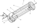
- 1 denotes a room air cleaner designed according to an advantageous embodiment of the invention, the housing, which is cylindrical in this case, not being shown.
- the room air cleaner 1 has an ozone generator 2 designed as a UV-C fluorescent tube in the example shown, which is arranged along a longitudinal axis 9 of the housing of the room air cleaner and, viewed radially, from an air guide component 3 at a predetermined distance which can vary when viewed axially and radially, is surrounded in a predetermined angular range.
- the ozone generator 2 can, as shown in the figure, be designed as a UV-C fluorescent tube, as a series connection of several UV LEDs or as a UV LED; Furthermore, the output of the ozone generator 2 used is preferably adjustable.
- the air guide component 3 is designed as a U-shaped profile, the edges of which run parallel to the longitudinal axis of the room air cleaner 1, the end of the air guide component 3 facing the air circulation unit 4 being designed in such a way that an air deflection component 8 can be arranged on this end.
- the air guide component 3 and the air deflection component 8 can also be made in one piece.
- the air guide component 3 can have a different shape; for example, the air guide component 3 can be designed as a cylinder segment with open ends.
- the room air purifier 1 comprises an air circulation unit 4, which in the example shown is designed as an axial fan and is arranged at one end of the housing, with this arrangement of the air circulation unit 4 advantageously having a substantially laminar flow from the axially opposite one End of the housing, comprising an air inlet opening 5 through the housing in the direction of the air circulation unit 4, is caused.
- an air outlet opening 6 is provided on the front side of the housing, through which air that is drawn into the interior of the device via the opposite air inlet opening 5 and enriched with ozone is expelled.
- the air outlet opening 6 is designed such that the air enriched with ozone is ejected in an evenly concentrated manner in an angular range between 0 and 90 ° with respect to the longitudinal axis 9, as illustrated by the arrows.
- the end face of the housing to which the air outlet opening 6 is assigned has a smaller diameter than the housing and, viewed axially, is arranged displaced outward by a predetermined amount.
- the specified dimension and the difference in the diameter of the end face of the housing and the housing are selected in such a way that the ozone generator cannot be seen from the outside. Without the axial displacement of the end face of the housing, between the end face of the Housing and the outer surface of the cylindrical housing, an annular gap is created.
- 7 is a plate to which the ozone generator 2, the air guide component 3, the air circulation unit 4 and other components, such as the electronics required to operate the room air cleaner, are attached.
- the inventive concept creates a room air purifier 1 in which the ozone concentration in the room in front of the air outlet opening 6 does not exceed predetermined threshold values.
- ozone is introduced into the room in the permitted concentration so that the air in the room itself is cleaned.
- the total amount of ozone required to purify the air in a room is emitted without, however, exceeding the values for the ozone concentration applicable according to the respective standard.
Landscapes
- Engineering & Computer Science (AREA)
- Chemical & Material Sciences (AREA)
- Combustion & Propulsion (AREA)
- Mechanical Engineering (AREA)
- General Engineering & Computer Science (AREA)
- Disinfection, Sterilisation Or Deodorisation Of Air (AREA)
- Filtering Of Dispersed Particles In Gases (AREA)
Description
- Die vorliegende Erfindung bezieht sich auf einen Raumluftreiniger gemäß dem Oberbegriff des Patentanspruchs 1.
- Aus dem Stand der Technik sind Raumluftreiniger bekannt, welche zumindest einen Ozongenerator aufweisen, der in einem Gehäuse mit einer Lufteintritts- und einer Luftaustrittsöffnung angeordnet ist. Hierbei ist ein Lüfter vorgesehen, welcher an der Lufteintrittsöffnung angeordnet ist und Luft in das Innere des Gehäuses ansaugt. Die Luft passiert den Ozongenerator, wobei sich das Ozon mit Geruchsmolekülen der Luft verbindet und Gerüche, Keime, Viren und Bakterien eliminiert. Die im Gerät gereinigte Luft wird anschließend in den Raum rückgeführt.
- Ferner sind derartig ausgeführte Raumluftreiniger bekannt, bei denen Ozon durch einen Ozongenerator erzeugt und mittels des an der Lufteintrittsöffnung angeordneten Lüfters aus dem Gerät in den Raum geblasen wird.
- Aus der
US 2005/069465 A1 ist ein Raumluftreiniger mit einem Ozongenerator bekannt, wobei die Luft durch Luftaustrittsöffnungen im Wesentlichen senkrecht zur Längsachse des Raumluftreinigers ausgestoßen wird Diese Druckschrift offenbart einen Raumluftreiniger nach dem Oberbegriff des Anspruchs 1. - Bei den aus dem Stand der Technik bekannten Geräten, welche Ozon in den Raum einbringen, um Gerüche zu neutralisieren, kommt es an der Luftaustrittsöffnung zu Konzentrationen, die vorgegebene Schwellenwerte für die Ozonkonzentration überschreiten. Aktuell sind 50 ppb in einem Abstand von 50 mm von der Luftaustrittsöffnung zugelassen.
- Der vorliegenden Erfindung liegt die Aufgabe zugrunde, einen Raumluftreiniger mit einem Ozongenerator anzugeben, durch dessen Verwendung Ozon in den Raum eingebracht wird, um die Luft im Raum zu reinigen, wobei die vorgegebenen Schwellenwerte für die Ozonkonzentration nicht überschritten werden.
- Diese Aufgabe wird durch die Merkmale des Patentanspruchs 1 gelöst. Weitere erfindungsgemäße Ausgestaltungen und Vorteile gehen aus den Unteransprüchen hervor.
- Demnach wird ein Raumluftreiniger vorgeschlagen, welcher ein Gehäuse umfasst, in dem entlang einer Längsachse des Gehäuses oder achsparallel dazu ein Ozongenerator, vorzugsweise ein Ozongenerator zur Bildung von Ozon mittels UV-Strahlung angeordnet ist, wobei der Ozongenerator radial betrachtet von einem Luftleitbauteil mit einem vorgegebenen Abstand in einem vorgegebenen Winkelbereich umgeben ist.
- Hierbei ist zumindest die dem Ozongenerator zugewandte Seite des Luftleitbauteils für die vom Ozongenerator emittierte Strahlung reflektierend ausgeführt. Ferner ist axial betrachtet an einem Ende des Gehäuses eine Luftumwälzeinheit angeordnet, welche geeignet ist, eine laminare Strömung vom axial betrachtet gegenüberliegenden Ende des Gehäuses, welches eine Lufteintrittsöffnung aufweist, durch das Gehäuse in Richtung auf die Luftumwälzeinheit zu verursachen.
- Gemäß der Erfindung ist axial betrachtet in Strömungsrichtung nach der Luftumwälzeinheit eine Luftaustrittsöffnung vorgesehen, über die in das Geräteinnere angesaugte und mit Ozon angereicherte Luft ausgestoßen wird, wobei die Luftaustrittsöffnung derart ausgeführt ist, dass die mit Ozon angereicherte Luft in den Raum gleichmäßig mit allen Winkeln in einem Winkelbereich zwischen 0 und 90° bezogen auf die Längsachse des Gehäuses gleichmäßig konzentriert ausgestoßen wird.
- Dadurch, dass zumindest die dem Ozongenerator zugewandte Seite des Luftleitbauteils reflektierend ausgeführt ist, wird gewährleistet, dass eine Entkeimung der Luft auch im Inneren des Gerätes stattfindet. Ferner wird durch die Anordnung der Luftumwälzeinheit an der Luftaustrittsöffnung eine im Wesentlichen laminare Luftströmung erzielt, wodurch gewährleistet wird, dass die Luft gleichmäßig mit Ozon gemischt wird, so dass Hotspots, nämlich durch Verwirbelung der Luft verursachte hohe örtliche Ozonkonzentrationen an der Luftaustrittsöffnung vermieden werden.
- Die Stirnseite des zylinderförmig ausgeführten Gehäuses, der die Luftaustrittsöffnung zugeordnet ist, weist einen geringeren Durchmesser als das Gehäuse auf und ist axial betrachtet um ein vorgegebenes Maß nach außen verschoben angeordnet.
- Durch die erfindungsgemäße Ausgestaltung der Luftaustrittsöffnung wird die Luft gleichmäßig konzentriert ausgestoßen ohne die vorgegebenen Schwellenwerte hinsichtlich der Ozonkonzentration zu überschreiten. Die Luftaustrittsöffnung ist derart dimensioniert, dass der UV-Generator von außen nicht direkt sichtbar ist und dass ein größtmöglicher Querschnitt zur Verfügung gestellt wird.
- Ferner wird durch die erfindungsgemäße Ausgestaltung der Luftaustrittsöffnung vermieden, dass die mit Ozon angereicherte Luft lediglich entlang einer Richtung in den Raum eingebracht wird, was die Ozonkonzentration in nachteiliger Weise erhöhen würde. Durch die Ausgestaltung der Luftaustrittsöffnung wird die Luft vorzugsweise viertelsphärisch ausgestoßen.
- Eine unerwünschte Verwirbelung der Luft im Inneren des Gerätes wird zudem durch das Vorsehen eines Luftumlenkbauteils gemäß einer Weiterbildung der Erfindung zusätzlich vermieden. Das Luftumlenkbauteil ist an dem der Luftumwälzeinheit zugewandten Ende des Luftleitbauteils auf dem radial betrachtet offenen Bereich des Luftleitbauteils axial betrachtet über eine vorgegebene Länge angeordnet. Ferner ist das Luftumlenkbauteil in Bezug auf die Längsachse vorzugsweise derart geneigt angeordnet, dass strömende Luft über das Luftleitbauteil der Luftumwälzeinheit zugeführt wird. Der Ozongenerator ist demnach an dessen der Luftumwälzeinheit zugewandten Ende von dem Luftumlenkbauteil und dem Luftleitbauteil radial betrachtet vollständig umgeben.
- Die Erfindung wird im Folgenden anhand der beigefügten Figur, welche eine schematische perspektivische Darstellung eines erfindungsgemäßen Raumluftreinigers ohne das Gehäuse darstellt, beispielhaft näher erläutert.
- In der beigefügten Figur ist mit 1 ein gemäß einer vorteilhaften Ausgestaltung der Erfindung ausgeführter Raumluftreiniger bezeichnet, wobei das in diesem Fall zylinderförmig ausgeführte Gehäuse nicht dargestellt ist.
- Der Raumluftreiniger 1 weist einen bei dem gezeigten Beispiel als UV-C Leuchtröhre ausgeführten Ozongenerator 2 auf, welcher entlang einer Längsachse 9 des Gehäuses des Raumluftreinigers angeordnet ist und radial betrachtet von einem Luftleitbauteil 3 mit einem vorgegebenen Abstand, der axial und radial betrachtet variieren kann, in einem vorgegebenen Winkelbereich umgeben ist. Der Ozongenerator 2 kann wie anhand der Figur dargestellt als UV-C Leuchtröhre, als eine Reihenschaltung mehrerer UV-LEDs oder als eine UV-LED ausgeführt sein; ferner ist die Leistung des verwendeten Ozongenerators 2 vorzugsweise einstellbar.
- Bei dem gezeigten Beispiel ist das Luftleitbauteil 3 als U-förmiges Profil ausgeführt, dessen Kanten parallel zur Längsachse des Raumluftreinigers 1 verlaufen, wobei das der Luftumwälzeinheit 4 zugewandte Ende des Luftleitbauteils 3 derart ausgeführt ist, dass auf diesem Ende ein Luftumlenkbauteil 8 anordenbar ist. Das Luftleitbauteil 3 und das Luftumlenkbauteil 8 können auch einstückig ausgeführt sein. Im Rahmen weiterer Ausführungsformen kann das Luftleitbauteil 3 eine andere Form aufweisen; beispielsweise kann das Luftleitbauteil 3 als Zylindersegment mit offenen Enden ausgeführt sein.
- Wie bereits beschrieben, umfasst der erfindungsgemäße Raumluftreiniger 1 eine Luftumwälzeinheit 4, die bei dem gezeigten Beispiel als Axiallüfter ausgeführt ist und an einem Ende des Gehäuses angeordnet ist, wobei durch diese Anordnung der Luftumwälzeinheit 4 im vorteilhafter Weise eine im Wesentlichen laminare Strömung vom axial betrachtet gegenüberliegenden Ende des Gehäuses, umfassend eine Lufteintrittsöffnung 5 durch das Gehäuse in Richtung auf die Luftumwälzeinheit 4, verursacht wird.
- Wie aus der Figur ersichtlich, ist axial betrachtet in Strömungsrichtung nach der Luftumwälzeinheit 4 an der Stirnseite des Gehäuses eine Luftaustrittsöffnung 6 vorgesehen, durch die in das Geräteinnere über die gegenüberliegende Lufteintrittsöffnung 5 angesaugte und mit Ozon angereicherte durchströmende Luft ausgestoßen wird.
- Die Luftaustrittsöffnung 6 ist erfindungsgemäß derart ausgeführt, dass die mit Ozon angereicherte Luft in einem Winkelbereich zwischen 0 und 90° bezogen auf die Längsachse 9 gleichmäßig konzentriert ausgestoßen wird, wie anhand der Pfeile veranschaulicht.
- Bei dem gezeigten Beispiel wird dies dadurch erreicht, dass die Stirnseite des Gehäuses, der die Luftaustrittsöffnung 6 zugeordnet ist, einen geringeren Durchmesser als das Gehäuse aufweist und axial betrachtet um ein vorgegebenes Maß nach außen verschoben angeordnet ist. Das vorgegebene Maß sowie die Differenz der Durchmesser der Stirnseite des Gehäuses und des Gehäuses sind derart gewählt, dass der Ozongenerator von außen uneinsehbar ist. Ohne die axiale Verschiebung der Stirnseite des Gehäuses würde zwischen der Stirnseite des Gehäuses und der Mantelfläche des zylinderförmigen Gehäuses ein Ringspalt entstehen.
- In der beigefügten Figur ist mit 7 eine Platte dargestellt, an der der Ozongenerator 2, das Luftleitbauteil 3, die Luftumwälzeinheit 4 und weitere Komponenten, wie beispielsweise die zum Betrieb des Raumluftreinigers erforderliche Elektronik angebracht sind.
- Durch die erfindungsgemäße Konzeption wird ein Raumluftreiniger 1 geschaffen, bei dem die Ozonkonzentration im Raum vor der Luftaustrittsöffnung 6 vorgegebene Schwellenwerte nicht überschreitet.
- Im Gegensatz zum Stand der Technik, wonach Ozonluftreiniger im Inneren der Geräte Luft durch eine hohe Ozonkonzentration reinigen und am Ende Frischluft ausstoßen, wird gemäß der Erfindung Ozon in der jeweils erlaubten Konzentration in den Raum eingebracht, so dass die Luft im Raum selbst gereinigt wird. Mittels der Erfindung wird die zur Luftreinigung eines Raums erforderliche Gesamtmenge an Ozon ausgestoßen, ohne jedoch die gemäß der jeweiligen Norm geltenden Werte für die Ozonkonzentration zu überschreiten.
Claims (8)
- Raumluftreiniger (1), umfassend ein Gehäuse, in dem entlang einer Längsachse des Gehäuses oder achsparallel dazu ein Ozongenerator (2) angeordnet ist, wobei der Ozongenerator (2) radial betrachtet von einem Luftleitbauteil (3) mit einem vorgegebenen Abstand in einem vorgegebenen Winkelbereich umgeben ist, wobei zumindest die dem Ozongenerator (2) zugewandte Seite des Luftleitbauteils (3) für die vom Ozongenerator (2) emittierte Strahlung reflektierend ausgeführt ist, wobei axial betrachtet an einem Ende des Gehäuses eine Luftumwälzeinheit (4) angeordnet ist, welche geeignet ist, eine laminare Strömung vom axial betrachtet gegenüberliegenden Ende des Gehäuses, welches eine Lufteintrittsöffnung (5) aufweist, durch das Gehäuse in Richtung auf die Luftumwälzeinheit (4) zu verursachen, wobei axial betrachtet in Strömungsrichtung nach der Luftumwälzeinheit (4) eine Luftaustrittsöffnung (6) vorgesehen ist, über die in das Geräteinnere angesaugte und mit Ozon angereicherte durchströmende Luft ausgestoßen wird, dadurch gekennzeichnet, dass die Luftaustrittsöffnung (6) derart ausgeführt ist, dass die mit Ozon angereicherte Luft in den Raum in einem Winkelbereich zwischen 0 und 90° bezogen auf die Längsachse gleichmäßig konzentriert ausgestoßen wird, wobei das Gehäuse zylinderförmig ausgeführt ist und die Luftaustrittsöffnung (6) dadurch realisiert wird, dass die Stirnseite des Gehäuses, der die Luftaustrittsöffnung (6) zugeordnet ist, einen geringeren Durchmesser aufweist als das Gehäuse und axial betrachtet um ein vorgegebenes Maß nach außen verschoben angeordnet ist.
- Raumluftreiniger (1) nach Anspruch 1, dadurch gekennzeichnet, dass an dem der Luftumwälzeinheit (4)zugewandten Ende des Luftleitbauteils (3) auf dem radial betrachtet offenen Bereich des Luftleitbauteils (3) axial betrachtet über eine vorgegebene Länge ein Luftumlenkbauteil (8) angeordnet ist, welches in Bezug auf die Längsachse derart geneigt angeordnet ist, dass strömende Luft über das Luftleitbauteil (4) der Luftumwälzeinheit zugeführt wird.
- Raumluftreiniger (1) nach Anspruch 2, dadurch gekennzeichnet, dass das Luftleitbauteil (3) als U-förmiges Profil ausgeführt ist, dessen Kanten parallel zur Längsachse des Raumluftreinigers (1) verlaufen, wobei das der Luftumwälzeinheit (4) zugewandte Ende des Luftleibauteils (3) derart ausgeführt ist, dass das Luftumlenkbauteil (8) auf dem radial betrachtet offenen Bereich des Luftleitbauteils (3) an diesem Ende angeordnet werden kann.
- Raumluftreiniger (1) nach Anspruch 2 oder 3, dadurch gekennzeichnet, dass das Luftleibauteil (3) und das Luftumlenkbauteil (8) einstückig ausgeführt sind.
- Raumluftreiniger (1) nach einem der vorangehenden Ansprüche, dadurch gekennzeichnet, dass der Ozongenerator (2) als Ozongenerator zur Bildung von Ozon mittels UV-Strahlung ausgeführt ist.
- Raumluftreiniger (1) nach Anspruch 5, dadurch gekennzeichnet, dass der Ozongenerator als UV-C Leuchtröhre ausgeführt ist oder zumindest eine UV-LED aufweist.
- Raumluftreiniger (1) nach einem der vorangehenden Ansprüche, dadurch gekennzeichnet, dass die Luftumwälzeinheit (4) als Axiallüfter ausgeführt ist.
- Raumluftreiniger (1) nach einem der vorangehenden Ansprüche, dadurch gekennzeichnet, dass die Leistung des Ozongenerators (2) einstellbar ist.
Priority Applications (5)
| Application Number | Priority Date | Filing Date | Title |
|---|---|---|---|
| ES17173019T ES2857084T3 (es) | 2017-05-26 | 2017-05-26 | Purificador de aire interior |
| DK17173019.5T DK3406977T3 (da) | 2017-05-26 | 2017-05-26 | Rumluftrenser |
| PL17173019T PL3406977T3 (pl) | 2017-05-26 | 2017-05-26 | Oczyszczacz powietrza do pomieszczenia |
| EP17173019.5A EP3406977B1 (de) | 2017-05-26 | 2017-05-26 | Raumluftreiniger |
| HRP20210217TT HRP20210217T1 (hr) | 2017-05-26 | 2021-02-09 | Sobni pročistač zraka |
Applications Claiming Priority (1)
| Application Number | Priority Date | Filing Date | Title |
|---|---|---|---|
| EP17173019.5A EP3406977B1 (de) | 2017-05-26 | 2017-05-26 | Raumluftreiniger |
Publications (2)
| Publication Number | Publication Date |
|---|---|
| EP3406977A1 EP3406977A1 (de) | 2018-11-28 |
| EP3406977B1 true EP3406977B1 (de) | 2020-12-16 |
Family
ID=58994843
Family Applications (1)
| Application Number | Title | Priority Date | Filing Date |
|---|---|---|---|
| EP17173019.5A Active EP3406977B1 (de) | 2017-05-26 | 2017-05-26 | Raumluftreiniger |
Country Status (5)
| Country | Link |
|---|---|
| EP (1) | EP3406977B1 (de) |
| DK (1) | DK3406977T3 (de) |
| ES (1) | ES2857084T3 (de) |
| HR (1) | HRP20210217T1 (de) |
| PL (1) | PL3406977T3 (de) |
Families Citing this family (4)
| Publication number | Priority date | Publication date | Assignee | Title |
|---|---|---|---|---|
| FR3100315B1 (fr) | 2019-08-27 | 2021-09-24 | Nateosante | purificateur d’air avec production et capture d’ozone. |
| CN111750452A (zh) * | 2020-07-08 | 2020-10-09 | 坤创科技(深圳)有限公司 | 一种医用灭菌空气净化器 |
| CN114777273B (zh) * | 2022-04-14 | 2024-12-06 | 山西宇航宏泽环保科技有限公司 | 一种柜式臭氧消毒机 |
| PL446537A1 (pl) * | 2023-10-27 | 2025-04-28 | Wiktor Woźniak | Ogrzewacz z odwróconą konwekcją |
Citations (10)
| Publication number | Priority date | Publication date | Assignee | Title |
|---|---|---|---|---|
| WO1992020974A1 (en) | 1991-05-17 | 1992-11-26 | Vertron International Pty. Limited | Disinfectant system |
| US20030072697A1 (en) | 2001-01-29 | 2003-04-17 | Sharper Image Corporation | Apparatus for conditioning air |
| US20030150708A1 (en) | 2000-07-12 | 2003-08-14 | Fink Ronald G. | Air treatment apparatus |
| US20050069465A1 (en) | 2003-09-29 | 2005-03-31 | Mcellen John J. | Light module for air treatment units |
| WO2005037409A1 (en) | 2003-10-15 | 2005-04-28 | Jimco A/S | Apparatus and method for cleaning contaminated air |
| GB2415879A (en) | 2004-06-28 | 2006-01-04 | John Se-Kit Yuen | Photo-electric air purifier system with carbon fiber ionising electrode |
| EP1688151A1 (de) | 2005-02-03 | 2006-08-09 | Se Kit Yuen | Elektro-optisches Luftreinigungs- und -staubfiltergerät |
| US20070253860A1 (en) | 2004-10-18 | 2007-11-01 | Werner Schroder | Process and device for sterilising ambient air |
| US20130287626A1 (en) | 2006-11-21 | 2013-10-31 | Karen Benedek | Apparatus and method for treating impurities in air and materials |
| WO2015126982A2 (en) | 2014-02-18 | 2015-08-27 | Rolf Engelhard | High efficiency ultra-violet reactor |
-
2017
- 2017-05-26 ES ES17173019T patent/ES2857084T3/es active Active
- 2017-05-26 EP EP17173019.5A patent/EP3406977B1/de active Active
- 2017-05-26 PL PL17173019T patent/PL3406977T3/pl unknown
- 2017-05-26 DK DK17173019.5T patent/DK3406977T3/da active
-
2021
- 2021-02-09 HR HRP20210217TT patent/HRP20210217T1/hr unknown
Patent Citations (10)
| Publication number | Priority date | Publication date | Assignee | Title |
|---|---|---|---|---|
| WO1992020974A1 (en) | 1991-05-17 | 1992-11-26 | Vertron International Pty. Limited | Disinfectant system |
| US20030150708A1 (en) | 2000-07-12 | 2003-08-14 | Fink Ronald G. | Air treatment apparatus |
| US20030072697A1 (en) | 2001-01-29 | 2003-04-17 | Sharper Image Corporation | Apparatus for conditioning air |
| US20050069465A1 (en) | 2003-09-29 | 2005-03-31 | Mcellen John J. | Light module for air treatment units |
| WO2005037409A1 (en) | 2003-10-15 | 2005-04-28 | Jimco A/S | Apparatus and method for cleaning contaminated air |
| GB2415879A (en) | 2004-06-28 | 2006-01-04 | John Se-Kit Yuen | Photo-electric air purifier system with carbon fiber ionising electrode |
| US20070253860A1 (en) | 2004-10-18 | 2007-11-01 | Werner Schroder | Process and device for sterilising ambient air |
| EP1688151A1 (de) | 2005-02-03 | 2006-08-09 | Se Kit Yuen | Elektro-optisches Luftreinigungs- und -staubfiltergerät |
| US20130287626A1 (en) | 2006-11-21 | 2013-10-31 | Karen Benedek | Apparatus and method for treating impurities in air and materials |
| WO2015126982A2 (en) | 2014-02-18 | 2015-08-27 | Rolf Engelhard | High efficiency ultra-violet reactor |
Non-Patent Citations (2)
| Title |
|---|
| JIMCO NORTH AMERICA: "Jimco MAC500", YOUTUBE, 12 May 2017 (2017-05-12), XP054982312, Retrieved from the Internet <URL:https://www.youtube.com/watch?v=M14pC_gtNugg> |
| WLADYSLAW KOWALSKI: "Ultraviolet Germicidal Irradiation Handbook", 2009, SPRINGER, article "Chapter 1", pages: 1 - 2, 135, 153, XP055847044 |
Also Published As
| Publication number | Publication date |
|---|---|
| PL3406977T3 (pl) | 2021-06-28 |
| ES2857084T3 (es) | 2021-09-28 |
| DK3406977T3 (da) | 2021-02-22 |
| EP3406977A1 (de) | 2018-11-28 |
| HRP20210217T1 (hr) | 2021-04-02 |
Similar Documents
| Publication | Publication Date | Title |
|---|---|---|
| EP3406977B1 (de) | Raumluftreiniger | |
| EP2344353B1 (de) | Luftreinigungssystem für fahrzeuge | |
| EP2858736A1 (de) | Filterelement mit filtertaschen | |
| EP4355694A1 (de) | Vorrichtung zur aufbereitung von wasser | |
| DE102007053028B4 (de) | Vorrichtung zur Bereitstellung eines Gas-/ Verbrennungsluft-Gemisches für einen Gasbrenner | |
| DE102011016464A1 (de) | Strömungsoptimierter Filterkopf | |
| WO2017042376A1 (de) | Vorrichtung zur bereitstellung von reinluft in einer getränkeabfüllanlage | |
| DE102019116745A1 (de) | Vorrichtung und Verfahren zum Desinfizieren eines Fluids mittels UV-Licht | |
| DE202021101555U1 (de) | Vorrichtung zur Filtration von Luft | |
| CH668712A5 (de) | Filteranordnung in einer farbspritz- und einbrennkabine. | |
| AT522780B1 (de) | Vorrichtung zur reinigung von gas | |
| DE102009030532A1 (de) | Rotorsystem zur Rückgewinnung der in der Fortluft von lufttechnischen Anlagen enthaltenen Wärmeenergie | |
| DE102010063843A1 (de) | Dunstabzugshaube und Verfahren zum Abscheiden von Aerosolen | |
| DE102016115577A1 (de) | Vakuum- und/oder Druck-Trommelfiltervorrichtung | |
| DE102019001372A1 (de) | Luftbehandlungsvorrichtung | |
| WO2016058580A1 (de) | Vorrichtung zur behandlung eines fluids mit uv-strahlung | |
| DE19618692A1 (de) | Filtervorrichtung für Fluide | |
| DE102019007536A1 (de) | Vorrichtung zur Verbesserung einer Innenraum-Luftqualität in einem Fahrzeug sowie ein Fahrzeug | |
| DE102020214983A1 (de) | Luftreinigungseinrichtung | |
| EP1772680A2 (de) | Vorrichtung und Verfahren zur Aufbereitung eines in einem Luftführungskanal geführten Luftstroms einer Klimaanlage | |
| EP4000656A2 (de) | Vorrichtung und verfahren zur reduzierung einer schadstoffbelastung in einem gas | |
| DE102017101458B3 (de) | Wasser/Partikel-Abscheider | |
| DE102015000360B4 (de) | Filter mit integrierter Pumpe | |
| DE202021000939U1 (de) | UVC-LED Entkeimungsvorrichtung für gasförmige Medien | |
| DE102015200849A1 (de) | Klimatisierungsanlage zum Klimatisieren eines Luftstroms |
Legal Events
| Date | Code | Title | Description |
|---|---|---|---|
| PUAI | Public reference made under article 153(3) epc to a published international application that has entered the european phase |
Free format text: ORIGINAL CODE: 0009012 |
|
| STAA | Information on the status of an ep patent application or granted ep patent |
Free format text: STATUS: REQUEST FOR EXAMINATION WAS MADE |
|
| 17P | Request for examination filed |
Effective date: 20171228 |
|
| AK | Designated contracting states |
Kind code of ref document: A1 Designated state(s): AL AT BE BG CH CY CZ DE DK EE ES FI FR GB GR HR HU IE IS IT LI LT LU LV MC MK MT NL NO PL PT RO RS SE SI SK SM TR |
|
| AX | Request for extension of the european patent |
Extension state: BA ME |
|
| STAA | Information on the status of an ep patent application or granted ep patent |
Free format text: STATUS: EXAMINATION IS IN PROGRESS |
|
| 17Q | First examination report despatched |
Effective date: 20190523 |
|
| GRAP | Despatch of communication of intention to grant a patent |
Free format text: ORIGINAL CODE: EPIDOSNIGR1 |
|
| STAA | Information on the status of an ep patent application or granted ep patent |
Free format text: STATUS: GRANT OF PATENT IS INTENDED |
|
| GRAS | Grant fee paid |
Free format text: ORIGINAL CODE: EPIDOSNIGR3 |
|
| GRAA | (expected) grant |
Free format text: ORIGINAL CODE: 0009210 |
|
| STAA | Information on the status of an ep patent application or granted ep patent |
Free format text: STATUS: THE PATENT HAS BEEN GRANTED |
|
| INTG | Intention to grant announced |
Effective date: 20201019 |
|
| REG | Reference to a national code |
Ref country code: DE Ref legal event code: R079 Ref document number: 502017008668 Country of ref document: DE Free format text: PREVIOUS MAIN CLASS: F24F0003160000 Ipc: F24F0008000000 |
|
| AK | Designated contracting states |
Kind code of ref document: B1 Designated state(s): AL AT BE BG CH CY CZ DE DK EE ES FI FR GB GR HR HU IE IS IT LI LT LU LV MC MK MT NL NO PL PT RO RS SE SI SK SM TR |
|
| REG | Reference to a national code |
Ref country code: GB Ref legal event code: FG4D Free format text: NOT ENGLISH |
|
| REG | Reference to a national code |
Ref country code: DE Ref legal event code: R096 Ref document number: 502017008668 Country of ref document: DE |
|
| REG | Reference to a national code |
Ref country code: IE Ref legal event code: FG4D Free format text: LANGUAGE OF EP DOCUMENT: GERMAN |
|
| REG | Reference to a national code |
Ref country code: AT Ref legal event code: REF Ref document number: 1345953 Country of ref document: AT Kind code of ref document: T Effective date: 20210115 |
|
| REG | Reference to a national code |
Ref country code: DK Ref legal event code: T3 Effective date: 20210217 |
|
| REG | Reference to a national code |
Ref country code: NL Ref legal event code: FP |
|
| REG | Reference to a national code |
Ref country code: CH Ref legal event code: NV Representative=s name: ABREMA SA, CH |
|
| REG | Reference to a national code |
Ref country code: HR Ref legal event code: T1PR Ref document number: P20210217 Country of ref document: HR |
|
| PG25 | Lapsed in a contracting state [announced via postgrant information from national office to epo] |
Ref country code: RS Free format text: LAPSE BECAUSE OF FAILURE TO SUBMIT A TRANSLATION OF THE DESCRIPTION OR TO PAY THE FEE WITHIN THE PRESCRIBED TIME-LIMIT Effective date: 20201216 Ref country code: NO Free format text: LAPSE BECAUSE OF FAILURE TO SUBMIT A TRANSLATION OF THE DESCRIPTION OR TO PAY THE FEE WITHIN THE PRESCRIBED TIME-LIMIT Effective date: 20210316 Ref country code: FI Free format text: LAPSE BECAUSE OF FAILURE TO SUBMIT A TRANSLATION OF THE DESCRIPTION OR TO PAY THE FEE WITHIN THE PRESCRIBED TIME-LIMIT Effective date: 20201216 Ref country code: GR Free format text: LAPSE BECAUSE OF FAILURE TO SUBMIT A TRANSLATION OF THE DESCRIPTION OR TO PAY THE FEE WITHIN THE PRESCRIBED TIME-LIMIT Effective date: 20210317 |
|
| PG25 | Lapsed in a contracting state [announced via postgrant information from national office to epo] |
Ref country code: SE Free format text: LAPSE BECAUSE OF FAILURE TO SUBMIT A TRANSLATION OF THE DESCRIPTION OR TO PAY THE FEE WITHIN THE PRESCRIBED TIME-LIMIT Effective date: 20201216 Ref country code: LV Free format text: LAPSE BECAUSE OF FAILURE TO SUBMIT A TRANSLATION OF THE DESCRIPTION OR TO PAY THE FEE WITHIN THE PRESCRIBED TIME-LIMIT Effective date: 20201216 Ref country code: BG Free format text: LAPSE BECAUSE OF FAILURE TO SUBMIT A TRANSLATION OF THE DESCRIPTION OR TO PAY THE FEE WITHIN THE PRESCRIBED TIME-LIMIT Effective date: 20210316 |
|
| REG | Reference to a national code |
Ref country code: HR Ref legal event code: ODRP Ref document number: P20210217 Country of ref document: HR Payment date: 20210519 Year of fee payment: 5 |
|
| REG | Reference to a national code |
Ref country code: LT Ref legal event code: MG9D |
|
| PG25 | Lapsed in a contracting state [announced via postgrant information from national office to epo] |
Ref country code: PT Free format text: LAPSE BECAUSE OF FAILURE TO SUBMIT A TRANSLATION OF THE DESCRIPTION OR TO PAY THE FEE WITHIN THE PRESCRIBED TIME-LIMIT Effective date: 20210416 Ref country code: SK Free format text: LAPSE BECAUSE OF FAILURE TO SUBMIT A TRANSLATION OF THE DESCRIPTION OR TO PAY THE FEE WITHIN THE PRESCRIBED TIME-LIMIT Effective date: 20201216 Ref country code: RO Free format text: LAPSE BECAUSE OF FAILURE TO SUBMIT A TRANSLATION OF THE DESCRIPTION OR TO PAY THE FEE WITHIN THE PRESCRIBED TIME-LIMIT Effective date: 20201216 Ref country code: SM Free format text: LAPSE BECAUSE OF FAILURE TO SUBMIT A TRANSLATION OF THE DESCRIPTION OR TO PAY THE FEE WITHIN THE PRESCRIBED TIME-LIMIT Effective date: 20201216 Ref country code: LT Free format text: LAPSE BECAUSE OF FAILURE TO SUBMIT A TRANSLATION OF THE DESCRIPTION OR TO PAY THE FEE WITHIN THE PRESCRIBED TIME-LIMIT Effective date: 20201216 Ref country code: CZ Free format text: LAPSE BECAUSE OF FAILURE TO SUBMIT A TRANSLATION OF THE DESCRIPTION OR TO PAY THE FEE WITHIN THE PRESCRIBED TIME-LIMIT Effective date: 20201216 Ref country code: EE Free format text: LAPSE BECAUSE OF FAILURE TO SUBMIT A TRANSLATION OF THE DESCRIPTION OR TO PAY THE FEE WITHIN THE PRESCRIBED TIME-LIMIT Effective date: 20201216 |
|
| PGFP | Annual fee paid to national office [announced via postgrant information from national office to epo] |
Ref country code: HR Payment date: 20210519 Year of fee payment: 5 |
|
| PGFP | Annual fee paid to national office [announced via postgrant information from national office to epo] |
Ref country code: PL Payment date: 20210518 Year of fee payment: 5 |
|
| REG | Reference to a national code |
Ref country code: DE Ref legal event code: R026 Ref document number: 502017008668 Country of ref document: DE |
|
| PLBI | Opposition filed |
Free format text: ORIGINAL CODE: 0009260 |
|
| PLAX | Notice of opposition and request to file observation + time limit sent |
Free format text: ORIGINAL CODE: EPIDOSNOBS2 |
|
| REG | Reference to a national code |
Ref country code: ES Ref legal event code: FG2A Ref document number: 2857084 Country of ref document: ES Kind code of ref document: T3 Effective date: 20210928 |
|
| PG25 | Lapsed in a contracting state [announced via postgrant information from national office to epo] |
Ref country code: IS Free format text: LAPSE BECAUSE OF FAILURE TO SUBMIT A TRANSLATION OF THE DESCRIPTION OR TO PAY THE FEE WITHIN THE PRESCRIBED TIME-LIMIT Effective date: 20210416 |
|
| 26 | Opposition filed |
Opponent name: JIMCO A/S Effective date: 20210916 |
|
| PG25 | Lapsed in a contracting state [announced via postgrant information from national office to epo] |
Ref country code: AL Free format text: LAPSE BECAUSE OF FAILURE TO SUBMIT A TRANSLATION OF THE DESCRIPTION OR TO PAY THE FEE WITHIN THE PRESCRIBED TIME-LIMIT Effective date: 20201216 |
|
| PLAF | Information modified related to communication of a notice of opposition and request to file observations + time limit |
Free format text: ORIGINAL CODE: EPIDOSCOBS2 |
|
| GBPC | Gb: european patent ceased through non-payment of renewal fee |
Effective date: 20210526 |
|
| PG25 | Lapsed in a contracting state [announced via postgrant information from national office to epo] |
Ref country code: LU Free format text: LAPSE BECAUSE OF NON-PAYMENT OF DUE FEES Effective date: 20210526 Ref country code: MC Free format text: LAPSE BECAUSE OF FAILURE TO SUBMIT A TRANSLATION OF THE DESCRIPTION OR TO PAY THE FEE WITHIN THE PRESCRIBED TIME-LIMIT Effective date: 20201216 |
|
| PG25 | Lapsed in a contracting state [announced via postgrant information from national office to epo] |
Ref country code: SI Free format text: LAPSE BECAUSE OF FAILURE TO SUBMIT A TRANSLATION OF THE DESCRIPTION OR TO PAY THE FEE WITHIN THE PRESCRIBED TIME-LIMIT Effective date: 20201216 |
|
| PLBB | Reply of patent proprietor to notice(s) of opposition received |
Free format text: ORIGINAL CODE: EPIDOSNOBS3 |
|
| PG25 | Lapsed in a contracting state [announced via postgrant information from national office to epo] |
Ref country code: IE Free format text: LAPSE BECAUSE OF NON-PAYMENT OF DUE FEES Effective date: 20210526 Ref country code: GB Free format text: LAPSE BECAUSE OF NON-PAYMENT OF DUE FEES Effective date: 20210526 |
|
| REG | Reference to a national code |
Ref country code: HR Ref legal event code: PBON Ref document number: P20210217 Country of ref document: HR Effective date: 20220526 |
|
| REG | Reference to a national code |
Ref country code: DE Ref legal event code: R082 Ref document number: 502017008668 Country of ref document: DE Representative=s name: KARAKATSANIS, GEORGIOS, DR., DE |
|
| PG25 | Lapsed in a contracting state [announced via postgrant information from national office to epo] |
Ref country code: HR Free format text: LAPSE BECAUSE OF NON-PAYMENT OF DUE FEES Effective date: 20220526 |
|
| PG25 | Lapsed in a contracting state [announced via postgrant information from national office to epo] |
Ref country code: CY Free format text: LAPSE BECAUSE OF FAILURE TO SUBMIT A TRANSLATION OF THE DESCRIPTION OR TO PAY THE FEE WITHIN THE PRESCRIBED TIME-LIMIT Effective date: 20201216 |
|
| PLCK | Communication despatched that opposition was rejected |
Free format text: ORIGINAL CODE: EPIDOSNREJ1 |
|
| REG | Reference to a national code |
Ref country code: DE Ref legal event code: R100 Ref document number: 502017008668 Country of ref document: DE |
|
| PG25 | Lapsed in a contracting state [announced via postgrant information from national office to epo] |
Ref country code: HU Free format text: LAPSE BECAUSE OF FAILURE TO SUBMIT A TRANSLATION OF THE DESCRIPTION OR TO PAY THE FEE WITHIN THE PRESCRIBED TIME-LIMIT; INVALID AB INITIO Effective date: 20170526 |
|
| PLBN | Opposition rejected |
Free format text: ORIGINAL CODE: 0009273 |
|
| STAA | Information on the status of an ep patent application or granted ep patent |
Free format text: STATUS: OPPOSITION REJECTED |
|
| 27O | Opposition rejected |
Effective date: 20230714 |
|
| PG25 | Lapsed in a contracting state [announced via postgrant information from national office to epo] |
Ref country code: MK Free format text: LAPSE BECAUSE OF FAILURE TO SUBMIT A TRANSLATION OF THE DESCRIPTION OR TO PAY THE FEE WITHIN THE PRESCRIBED TIME-LIMIT Effective date: 20201216 |
|
| PG25 | Lapsed in a contracting state [announced via postgrant information from national office to epo] |
Ref country code: PL Free format text: LAPSE BECAUSE OF NON-PAYMENT OF DUE FEES Effective date: 20220526 |
|
| PG25 | Lapsed in a contracting state [announced via postgrant information from national office to epo] |
Ref country code: MT Free format text: LAPSE BECAUSE OF FAILURE TO SUBMIT A TRANSLATION OF THE DESCRIPTION OR TO PAY THE FEE WITHIN THE PRESCRIBED TIME-LIMIT Effective date: 20201216 |
|
| PGFP | Annual fee paid to national office [announced via postgrant information from national office to epo] |
Ref country code: NL Payment date: 20250522 Year of fee payment: 9 |
|
| PGFP | Annual fee paid to national office [announced via postgrant information from national office to epo] |
Ref country code: DE Payment date: 20250513 Year of fee payment: 9 |
|
| PGFP | Annual fee paid to national office [announced via postgrant information from national office to epo] |
Ref country code: ES Payment date: 20250616 Year of fee payment: 9 Ref country code: DK Payment date: 20250521 Year of fee payment: 9 |
|
| PGFP | Annual fee paid to national office [announced via postgrant information from national office to epo] |
Ref country code: BE Payment date: 20250520 Year of fee payment: 9 Ref country code: IT Payment date: 20250530 Year of fee payment: 9 |
|
| PGFP | Annual fee paid to national office [announced via postgrant information from national office to epo] |
Ref country code: FR Payment date: 20250521 Year of fee payment: 9 |
|
| PGFP | Annual fee paid to national office [announced via postgrant information from national office to epo] |
Ref country code: CH Payment date: 20250601 Year of fee payment: 9 |
|
| PGFP | Annual fee paid to national office [announced via postgrant information from national office to epo] |
Ref country code: AT Payment date: 20250519 Year of fee payment: 9 |
|
| PG25 | Lapsed in a contracting state [announced via postgrant information from national office to epo] |
Ref country code: TR Free format text: LAPSE BECAUSE OF FAILURE TO SUBMIT A TRANSLATION OF THE DESCRIPTION OR TO PAY THE FEE WITHIN THE PRESCRIBED TIME-LIMIT Effective date: 20201216 |