EP3406910A1 - Centrifugal fan impeller - Google Patents
Centrifugal fan impeller Download PDFInfo
- Publication number
- EP3406910A1 EP3406910A1 EP17741322.6A EP17741322A EP3406910A1 EP 3406910 A1 EP3406910 A1 EP 3406910A1 EP 17741322 A EP17741322 A EP 17741322A EP 3406910 A1 EP3406910 A1 EP 3406910A1
- Authority
- EP
- European Patent Office
- Prior art keywords
- shroud
- portions
- blade
- end portions
- axial end
- Prior art date
- Legal status (The legal status is an assumption and is not a legal conclusion. Google has not performed a legal analysis and makes no representation as to the accuracy of the status listed.)
- Granted
Links
Images





Classifications
-
- F—MECHANICAL ENGINEERING; LIGHTING; HEATING; WEAPONS; BLASTING
- F04—POSITIVE - DISPLACEMENT MACHINES FOR LIQUIDS; PUMPS FOR LIQUIDS OR ELASTIC FLUIDS
- F04D—NON-POSITIVE-DISPLACEMENT PUMPS
- F04D29/00—Details, component parts, or accessories
- F04D29/26—Rotors specially for elastic fluids
- F04D29/28—Rotors specially for elastic fluids for centrifugal or helico-centrifugal pumps for radial-flow or helico-centrifugal pumps
- F04D29/281—Rotors specially for elastic fluids for centrifugal or helico-centrifugal pumps for radial-flow or helico-centrifugal pumps for fans or blowers
-
- F—MECHANICAL ENGINEERING; LIGHTING; HEATING; WEAPONS; BLASTING
- F04—POSITIVE - DISPLACEMENT MACHINES FOR LIQUIDS; PUMPS FOR LIQUIDS OR ELASTIC FLUIDS
- F04D—NON-POSITIVE-DISPLACEMENT PUMPS
- F04D29/00—Details, component parts, or accessories
- F04D29/26—Rotors specially for elastic fluids
- F04D29/28—Rotors specially for elastic fluids for centrifugal or helico-centrifugal pumps for radial-flow or helico-centrifugal pumps
-
- F—MECHANICAL ENGINEERING; LIGHTING; HEATING; WEAPONS; BLASTING
- F04—POSITIVE - DISPLACEMENT MACHINES FOR LIQUIDS; PUMPS FOR LIQUIDS OR ELASTIC FLUIDS
- F04D—NON-POSITIVE-DISPLACEMENT PUMPS
- F04D29/00—Details, component parts, or accessories
- F04D29/26—Rotors specially for elastic fluids
- F04D29/28—Rotors specially for elastic fluids for centrifugal or helico-centrifugal pumps for radial-flow or helico-centrifugal pumps
- F04D29/30—Vanes
-
- F—MECHANICAL ENGINEERING; LIGHTING; HEATING; WEAPONS; BLASTING
- F04—POSITIVE - DISPLACEMENT MACHINES FOR LIQUIDS; PUMPS FOR LIQUIDS OR ELASTIC FLUIDS
- F04D—NON-POSITIVE-DISPLACEMENT PUMPS
- F04D29/00—Details, component parts, or accessories
- F04D29/60—Mounting; Assembling; Disassembling
- F04D29/62—Mounting; Assembling; Disassembling of radial or helico-centrifugal pumps
- F04D29/624—Mounting; Assembling; Disassembling of radial or helico-centrifugal pumps especially adapted for elastic fluid pumps
- F04D29/626—Mounting or removal of fans
-
- F—MECHANICAL ENGINEERING; LIGHTING; HEATING; WEAPONS; BLASTING
- F04—POSITIVE - DISPLACEMENT MACHINES FOR LIQUIDS; PUMPS FOR LIQUIDS OR ELASTIC FLUIDS
- F04D—NON-POSITIVE-DISPLACEMENT PUMPS
- F04D29/00—Details, component parts, or accessories
- F04D29/66—Combating cavitation, whirls, noise, vibration or the like; Balancing
Definitions
- the present invention relates to a centrifugal fan impeller, and particularly a centrifugal fan impeller equipped with plural blades that are annularly disposed around a rotational axis and a main plate and a shroud that are disposed so as to sandwich the rotational axis direction sides of the blades, with blade axial end portions, which are end portions of the blades on one side in the rotational axis direction, and the shroud being welded to each other.
- centrifugal fans are sometimes used for the purpose of sucking in, supplying, and exhausting air.
- An impeller configuring the centrifugal fan mainly has plural blades that are annularly disposed around a rotational axis and a main plate and a shroud that are disposed so as to sandwich the rotational axis direction sides of the blades.
- centrifugal fan impellers where blade axial end portions, which are end portions of the blades on one side in the rotational axis direction, and the shroud are welded to each other.
- the blade axial end portions along the entire chord length direction and the corresponding sections of the shroud are given staircase shapes, and flat surfaces of the staircase shapes are welded to each other.
- a centrifugal fan impeller pertaining to a first aspect has plural blades that are annularly disposed around a rotational axis and a main plate and a shroud that are disposed so as to sandwich the rotational axis direction sides of the blades, with blade axial end portions, which are end portions of the blades on one side in the rotational axis direction, and the shroud being welded to each other.
- the shroud has a curved plate-like shroud curved plate portion curved in such a way that its diameter becomes smaller heading away from the blades in the rotational axis direction and flat plate-like shroud flat plate portions formed in correspondence to just parts of the sections of the shroud that oppose the blade axial end portions.
- blade flat surfaces being flat surfaces that follow the shroud flat plate portions and blade curved surfaces being curved surfaces that follow the shroud curved plate portion.
- Welded portions resulting from the blade flat surfaces and the shroud flat plate portions being welded to each other are formed between the blade axial end portions and the shroud.
- the centrifugal fan impeller employs a structure where the sections at which the blades and the shroud oppose each other are largely left as a curved plate portion (the shroud curved plate portion) and curved surfaces (the blade curved surfaces) and where flat plate portions (the shroud flat plate portions) and flat surfaces (the blade flat surfaces) are formed, and welded to each other, in just parts of the sections at which the blades and the shroud oppose each other.
- the impeller employs a conventional structure where staircase shapes are formed in the blades and the shroud and welded to each other, it becomes difficult for the airflow in the vicinity of the shroud to be obstructed.
- the airflow in the vicinity of the shroud can be improved to thereby achieve an improvement in blowing performance and a reduction in blowing noise.
- a centrifugal fan impeller pertaining to a second aspect is the centrifugal fan impeller pertaining to the first aspect, wherein the blade flat surfaces are disposed in the vicinities of chord length direction centers of the blade axial end portions.
- the welding of the blades and the shroud to each other is performed at the sections in the vicinities of the chord length direction centers of the blade axial end portions, so in comparison to a case where the welding of the blades and the shroud to each other is performed at the sections on the leading edge sides and/or the trailing edge-side sections of the blade axial end portions, robust welding becomes possible.
- a centrifugal fan impeller pertaining to a third aspect is the centrifugal fan impeller pertaining to the second aspect, wherein leading edge-side recessed portions, into which leading edge-side sections of the blade axial end portions are insertable, are formed in the shroud in such a way as to follow the blade curved surfaces.
- the leading edge-side recessed portions into which the leading edge-side sections of the blade axial end portions are insertable, are formed in the shroud. For this reason, disruption of the airflow caused by gaps between the leading edge-side sections of the blade axial end portions and the shroud can be curbed.
- the leading edge-side recessed portions are formed in the shroud, there is an adverse impact on blowing performance and blowing noise, but here, as described above, by forming the leading edge-side recessed portions in such a way as to follow the blade curved surfaces, the adverse impact on blowing performance and blowing noise caused by the leading edge-side recessed portions is curbed.
- a centrifugal fan impeller pertaining to a fourth aspect is the centrifugal fan impeller pertaining to the third aspect, wherein the leading edge-side recessed portions project from the shroud curved plate portion in such a way as to form curved plate portions parallel to the shroud curved plate portion.
- a centrifugal fan impeller pertaining to a fifth aspect is the centrifugal fan impeller pertaining to any of the second to fourth aspects, wherein trailing edge-side raised portions are formed in the shroud in such a way as to line trailing edge-side sections of the blade axial end portions.
- the flat plate portions (the shroud flat plate portions) and the flat surfaces (the blade flat surfaces) are formed, and welded to each other, in just parts of the sections at which the blades and the shroud oppose each other, when the welding of the blades and the shroud to each other is performed at the sections in the vicinities of the chord length direction centers of the blade axial end portions, there is the concern that gaps will form between the trailing edge-side sections of the blade axial end portions and the shroud curved plate portion because of, for example, strain during the molding of the blades and the shroud.
- the trailing edge-side raised portions are formed in the shroud in such a way as to line the trailing edge-side sections of the blade axial end portions. For this reason, leakage of the airflow caused by gaps between the trailing edge-side sections of the blade axial end portions and the shroud curved plate portion can be curbed.
- a centrifugal fan impeller pertaining to a sixth aspect is the centrifugal fan impeller pertaining to the fifth aspect, wherein the trailing edge-side raised portions are disposed in correspondence to just positive pressure surface sides of the blade axial end portions.
- centrifugal fan impeller pertaining to the present invention will be described below on the basis of the drawings. It will be noted that the specific configurations of the centrifugal fan impeller pertaining to the present invention are not limited to those in the following embodiment and example modification and can be changed in a range that does not depart from the spirit of the invention.
- FIG. 1 an external perspective view (with a ceiling being omitted) of an air conditioning apparatus 1 in which a centrifugal fan 4 equipped with an impeller 8 pertaining to an embodiment of the present invention is employed.
- the air conditioning apparatus 1 here is an air conditioning apparatus installed in a ceiling and mainly has a casing 2, which houses various constituent devices inside, and a decorative panel 3, which is disposed on the lower side of the casing 2.
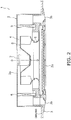
- the casing 2 of the air conditioning apparatus 1 is a box-like member whose undersurface is open. As shown in FIG. 2 (a general side sectional view of the air conditioning apparatus 1), the casing 2 is inserted and disposed in an opening formed in a ceiling of an air-conditioned room. Additionally, the decorative panel 3 has an air inlet 3a, which is disposed in the substantial center of the decorative panel 3 in order to suck the air in the air-conditioned room into the casing 2, and air outlets 3b, which are disposed so as to surround the outer periphery of the air inlet 3a in order to blow the air out from the casing 2 to the air-conditioned room. The decorative panel 3 is disposed in such a way as to be fitted into the opening in the ceiling.
- centrifugal fan 4 Mainly disposed inside the casing 2 are a centrifugal fan 4 that sucks the air in the air-conditioned room into the casing 2 through the air inlet 3a in the decorative panel 3 and blows the air out in an outer peripheral direction, a heat exchanger 5 that surrounds the outer periphery of the centrifugal fan 4, and a bell mouth 6 for guiding the air sucked in from the air inlet 3a to the centrifugal fan 4.
- the centrifugal fan 4 has a fan motor 7, which is provided in the substantial center of a top plate 2a of the casing 2, and the impeller 8, which is coupled to and driven to rotate by the fan motor 7.
- the air conditioning apparatus 1 provided with the centrifugal fan 4 is not limited to an apparatus installed in a ceiling and may also be another type. Furthermore, the configuration of the impeller 8 will be described later.
- FIG. 3 is an external perspective view of the impeller 8.
- FIG. 4 is a view seen in the direction of arrow A in FIG. 3 (with part of a shroud 80 being excluded).
- FIG. 5 is a view seen in the direction of arrow B in FIG. 3 (with part of a main plate 60 being excluded).
- FIG. 6 is an enlarged view of portion C in FIG. 4 .
- FIG. 7 is an enlarged view of portion D in FIG. 5 .
- FIG. 8 is a view showing a cross section along line IV-IV of FIG. 7 .
- FIG. 9 is a view showing a cross section along line I-I of FIG. 6 .
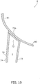
- FIG. 10 is a view showing a cross section along line II-II of FIG. 6 .
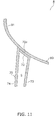
- FIG. 11 is a view showing a cross section along line III-III of FIG. 6 .
- the impeller 8 mainly has a disc-shaped main plate 60 that is coupled to the fan motor 7, plural (here, seven) blades 70 that are annularly disposed around a rotational axis O of the main plate 60 on the side of the main plate 60 opposite the fan motor 7 side, and an annular shroud 80 that is disposed so as to sandwich the plural blades 70 between itself and the main plate 60 in the direction of the rotational axis O.
- R denotes the rotational direction of the impeller 8.
- the main plate 60 is a member made of resin having a substantially circular truncated cone-shaped hub portion 61 formed in the central portion thereof so as to project toward the air inlet 3a side.
- Formed in the hub portion 61 are, for example, plural (here, three) cooling-use air holes 62 being long holes formed adjacent to each other on a circle concentric with the main plate 60.
- the section of the main plate 60 on the outer peripheral side of the hub portion 61 is an annular flat plate-like flat plate portion 63.
- the shroud 80 is a bell-shaped member made of resin that projects while curving toward the air inlet 3a side heading from its outer peripheral portion toward an opening in its central portion.
- the curved plate-like section of the shroud 80 that curves in such a way that its diameter becomes smaller heading away from the blades 70 in the rotational axis O direction (i.e., heading toward the air inlet 3a side) is a shroud curved plate portion 81.
- the blades 70 here are members made of resin molded separately from the main plate 60 and the shroud 80. End portions of the blades 70 on one side in the rotational axis O direction are main plate-side blade axial end portions 71 disposed opposing the main plate 60 and are secured to the main plate 60. End portions of the blades 70 on the other side in the rotational axis O direction are shroud-side blade axial end portions 72 disposed opposing the shroud 80 and are secured to the shroud 80.
- the blades 70 have a shape where, when the impeller 8 is viewed along the rotational axis O direction, the main plate-side blade axial end portions 71 are rearwardly inclined beyond the shroud-side blade axial end portions 72.
- the blades 70 are hollow blades mainly having blade bodies 73 and blade covers 74, and the blade covers 74 are attached to the blade bodies 73 by being fitted therein and form hollow spaces S between themselves and the blade bodies 73, whereby the blades 70 are reduced in weight.
- the hollowing of the blades 70 may also be accomplished by blow molding, for example, rather than being accomplished by a structure where the two members 73 and 74 are fitted together.
- concavo-convex shapes for improving the performance of the centrifugal fan 4 are formed in the trailing edge portions of the blades 70, but in a case where sufficient performance can be obtained without forming the concavo-convex shapes, it is not invariably necessary to form the concavo-convex shapes.
- the blades 70 are members separate from the main plate 60 and the shroud 80, but the blades 70 are not limited to this and may also be molded integrally with the main plate 60. In this case, it suffices simply to secure the blades 70 to the shroud 80.
- the securing of the main plate-side blade axial end portions 71 of the blades 70 to the main plate 60 is performed by welding the main plate-side blade axial end portions 71 and the main plate 60 to each other, and the welded sections form main plate-side welded portions 8a.
- a method that applies ultrasonic waves to the flat plate portion 63 of the main plate 60 and flat surfaces 71a of the main plate-side blade axial end portions 71 of the blades 70 to thereby weld the flat plate portion 63 and the flat surfaces 71a to each other (ultrasonic welding) is employed.
- the method of welding the blades 70 to the main plate 60 is not limited to ultrasonic welding so long as it is a method of welding the flat plate portion 63 and the flat surfaces 71a to each other, and another welding method may also be employed, such as, for example, employing a method that applies a laser to the flat plate portion 63 and the flat surfaces 71a to thereby weld the flat plate portion 63 and the flat surfaces 71a to each other (laser welding).
- the securing of the shroud-side blade axial end portions 72 of the blades 70 to the shroud 80 is performed by welding the shroud-side blade axial end portions 72 and the shroud 80 to each other, and the welded sections form shroud-side welded portions 8b.
- flat plate-like shroud flat plate portions 82 are formed in the shroud 80 in correspondence to just parts of the sections of the shroud 80 that oppose the shroud-side blade axial end portions 72, and the shroud-side welded portions 8b are disposed in the shroud flat plate portions 82.
- the shroud 80 is largely configured by the curved plate-like shroud curved plate portion 81 curved in such a way that its diameter becomes smaller heading away from the blades 70 in the rotational axis O direction, but the flat plate-like flat plate portions 82 perpendicular to the rotational axis O direction are formed in just parts of the sections of the shroud curved plate portion 81 corresponding to the shroud-side blade axial end portions 72.
- blade flat surfaces 72a being flat surfaces that follow the shroud flat plate portions 82 and blade curved surfaces 72b and 72c being curved surfaces that follow the shroud curved plate portion 81.
- the shroud-side welded portions 8b are formed as a result of the blade flat surfaces 72a and the shroud flat plate portions 82 being welded to each other.
- a method that applies ultrasonic waves to the shroud flat plate portions 82 of the shroud 80 and the blade flat surfaces 72a of the shroud-side blade axial end portions 72 of the blades 70 to thereby weld the shroud flat plate portions 82 and the blade flat surfaces 72a to each other (ultrasonic welding) is employed.
- the method of welding the blades 70 to the shroud 80 is not limited to ultrasonic welding so long as it is a method of welding the shroud flat plate portions 82 and the blade flat surfaces 72a to each other, and another welding method may also be employed, such as, for example, employing a method that applies a laser to the shroud flat plate portions 82 and the blade flat surfaces 72a to thereby weld the shroud flat plate portions 82 and the blade flat surfaces 72a to each other (laser welding).
- the blade flat surfaces 72a are disposed so as to correspond to the vicinities of chord length direction centers of the shroud-side blade axial end portions 72.
- the shroud flat plate portions 82 are also disposed in the vicinities of the chord length direction centers of the shroud-side blade axial end portions 72.
- shroud step portions 83 that interconnect the shroud flat plate portions 82 and the shroud curved plate portion 81 are formed in the shroud 80 on the peripheral sections of the shroud flat plate portions 82, and blade stepped portions 72d that can fit together with the shroud stepped portions 83 and interconnect the blade curved surfaces 72b and 72c are formed in the shroud-side blade axial end portions 72 on the peripheral sections of the blade flat surfaces 72a.
- the blade stepped portions 77 are configured to fit together with the shroud stepped portions 83 in a state in which the shroud flat plate portions 82 and the blade flat plate portions 72a lie on top of each other in the rotational axis O direction. That is, the blades 70 are positioned in predetermined positions on the shroud 80 because of the shroud stepped portions 83 and the blade stepped portions 72d.
- the impeller 8 of the centrifugal fan 4 has the following characteristics in relation to the structure in the vicinity of the shroud-side welded portions 8b formed between the shroud-side blade axial end portions 72 of the blades 70 and the shroud 80.
- the shroud 80 has the curved plate-like shroud curved plate portion 81 and the flat plate-like shroud flat plate portions 82 formed in correspondence to just parts of the sections of the shroud 80 that oppose the blade axial end portions 72.
- the blade flat surfaces 72a being flat surfaces that follow the shroud flat plate portions 82
- the blade curved surfaces 72b and 72c being curved surfaces that follow the shroud curved plate portion 81.
- the welded portions 8b resulting from the blade flat surfaces 72a and the shroud flat plate portions 82 being welded to each other are formed between the blade axial end portions 72 and the shroud 80.
- the impeller 8 employs a structure where the sections at which the blades 70 and the shroud 80 oppose each other are largely left as a curved plate portion (the shroud curved plate portion 81) and curved surfaces (the blade curved surfaces 72b and 72c) and where flat plate portions (the shroud flat plate portions 82) and flat surfaces (the blade flat surfaces 72a) are formed, and welded to each other, in just parts of the sections at which the blades 70 and the shroud 80 oppose each other.
- the airflow in the vicinity of the shroud 80 can be improved to thereby achieve an improvement in blowing performance and a reduction in blowing noise.
- the welding of the blades 70 and the shroud 80 to each other is performed at the sections in the vicinities of the chord length direction centers of the blade axial end portions 72. For this reason, in comparison to a case where the welding of the blades 70 and the shroud 80 to each other is performed at the leading edge-side sections and/or the trailing edge-side sections of the blade axial end portions 72, robust welding becomes possible.
- the flat plate portions (the shroud flat plate portions 82) and the flat surfaces (the blade flat surfaces 72a) are formed, and welded to each other, in just parts of the sections at which the blades 70 and the shroud 80 oppose each other, when the welding of the blades 70 and the shroud 80 to each other is performed at the sections in the vicinities of the chord length direction centers of the blade axial end portions (see FIG. 9 ), there is the concern that gaps will form between the leading edge-side sections of the shroud-side blade axial end portions 72 and the shroud curved plate portion 81 because of, for example, strain during the molding of the blades 70 and the shroud 80 (see FIG. 10 ).
- gaps at the leading edge-side sections of the shroud-side blade axial end portions 72 cause a disruption in the airflow heading through the opening in the central portion of the shroud 80 toward the leading edges of the blades 70, so there is the concern that this will increase blowing noise.
- leading edge-side recessed portions 84 into which the leading edge-side sections of the shroud-side blade axial end portions 72 are insertable, are formed in the shroud 80. For this reason, disruption of the airflow caused by gaps between the leading edge-side sections of the shroud-side blade axial end portions 72 and the shroud curved plate portion 81 can be curbed.
- leading edge-side recessed portions 84 are formed in the shroud 80, there is an adverse impact on blowing performance and blowing noise, but here, by forming the leading edge-side recessed portions 84 in such a way as to follow the blade curved surfaces 72b, the adverse impact on blowing performance and blowing noise caused by the leading edge-side recessed portions 84 is curbed.
- the leading edge-side recessed portions 84 project from the shroud curved plate portion 81 toward the side opposite the blade 70 side in the rotational axis O direction in such a way as to form curved plate portions parallel to the shroud curved plate portion 81.
- a seal material may be disposed between the leading edge-side sections of the shroud-side blade axial end portions 72 and the leading edge-side recessed portions 84 in order to further enhance the effect of curbing disruption of the airflow caused by gaps between the leading edge-side sections of the shroud-side blade axial end portions 72 and the shroud curved plate portion 81. Furthermore, in a case where it is possible to satisfy the blowing performance and the blowing noise required of the impeller 8 without forming the leading edge-side recessed portions 84, it is alright not to form the leading edge-side recessed portions 84.
- gaps at the trailing edge-side sections of the shroud-side blade axial end portions 72 cause some of the airflow heading along the positive pressure surfaces of the blades 70 from the leading edges to the trailing edges to leak midway from the positive pressure surface sides to the negative pressure surface sides, so there is the concern that this will reduce blowing performance.
- trailing edge-side raised portions 85 are formed in the shroud 80 in such a way as to line the trailing edge-side sections of the shroud-side blade axial end portions 72. For this reason, leakage of the airflow caused by gaps between the trailing edge-side sections of the shroud-side blade axial end portions 72 and the shroud curved plate portion 81 can be curbed.
- the trailing edge-side raised portions 85 are disposed in correspondence to just the positive pressure surface sides of the shroud-side blade axial end portions 72.
- the present invention is widely applicable to a centrifugal fan impeller equipped with plural blades that are annularly disposed around a rotational axis and a main plate and a shroud that are disposed so as to sandwich the rotational axis direction sides of the blades, with blade axial end portions, which are end portions of the blades on one side in the rotational axis direction, and the shroud being welded to each other.
Landscapes
- Engineering & Computer Science (AREA)
- Mechanical Engineering (AREA)
- General Engineering & Computer Science (AREA)
- Structures Of Non-Positive Displacement Pumps (AREA)
Abstract
Description
- The present invention relates to a centrifugal fan impeller, and particularly a centrifugal fan impeller equipped with plural blades that are annularly disposed around a rotational axis and a main plate and a shroud that are disposed so as to sandwich the rotational axis direction sides of the blades, with blade axial end portions, which are end portions of the blades on one side in the rotational axis direction, and the shroud being welded to each other.
- In air conditioning apparatuses and air purifiers, for example, centrifugal fans are sometimes used for the purpose of sucking in, supplying, and exhausting air. An impeller configuring the centrifugal fan mainly has plural blades that are annularly disposed around a rotational axis and a main plate and a shroud that are disposed so as to sandwich the rotational axis direction sides of the blades.
- Additionally, as such a centrifugal fan impeller, there are, as disclosed in
patent documents 1 and 2 (JP-ANo. 2005-155510 JP-A No. 2015-86827 - In
patent documents - It is a problem of the present invention to achieve an improvement in blowing performance and a reduction in blowing noise in a centrifugal fan impeller equipped with plural blades that are annularly disposed around a rotational axis and a main plate and a shroud that are disposed so as to sandwich the rotational axis direction sides of the blades, with blade axial end portions, which are end portions of the blades on one side in the rotational axis direction, and the shroud being welded to each other.
- A centrifugal fan impeller pertaining to a first aspect has plural blades that are annularly disposed around a rotational axis and a main plate and a shroud that are disposed so as to sandwich the rotational axis direction sides of the blades, with blade axial end portions, which are end portions of the blades on one side in the rotational axis direction, and the shroud being welded to each other. Additionally, here, the shroud has a curved plate-like shroud curved plate portion curved in such a way that its diameter becomes smaller heading away from the blades in the rotational axis direction and flat plate-like shroud flat plate portions formed in correspondence to just parts of the sections of the shroud that oppose the blade axial end portions. In the blade axial end portions are formed blade flat surfaces being flat surfaces that follow the shroud flat plate portions and blade curved surfaces being curved surfaces that follow the shroud curved plate portion. Welded portions resulting from the blade flat surfaces and the shroud flat plate portions being welded to each other are formed between the blade axial end portions and the shroud.
- Here, as described above, the centrifugal fan impeller employs a structure where the sections at which the blades and the shroud oppose each other are largely left as a curved plate portion (the shroud curved plate portion) and curved surfaces (the blade curved surfaces) and where flat plate portions (the shroud flat plate portions) and flat surfaces (the blade flat surfaces) are formed, and welded to each other, in just parts of the sections at which the blades and the shroud oppose each other. For this reason, here, in comparison to a case where the impeller employs a conventional structure where staircase shapes are formed in the blades and the shroud and welded to each other, it becomes difficult for the airflow in the vicinity of the shroud to be obstructed.
- Because of this, here, the airflow in the vicinity of the shroud can be improved to thereby achieve an improvement in blowing performance and a reduction in blowing noise.
- A centrifugal fan impeller pertaining to a second aspect is the centrifugal fan impeller pertaining to the first aspect, wherein the blade flat surfaces are disposed in the vicinities of chord length direction centers of the blade axial end portions.
- Here, as described above, in employing a structure where the flat plate portions (the shroud flat plate portions) and the flat surfaces (the blade flat surfaces) are formed, and welded to each other, in just parts of the sections at which the blades and the shroud oppose each other, the welding of the blades and the shroud to each other is performed at the sections in the vicinities of the chord length direction centers of the blade axial end portions, so in comparison to a case where the welding of the blades and the shroud to each other is performed at the sections on the leading edge sides and/or the trailing edge-side sections of the blade axial end portions, robust welding becomes possible.
- Because of this, here, the area of the blade flat surfaces required for welding and the area of the shroud flat plate portion corresponding thereto can be reduced.
- A centrifugal fan impeller pertaining to a third aspect is the centrifugal fan impeller pertaining to the second aspect, wherein leading edge-side recessed portions, into which leading edge-side sections of the blade axial end portions are insertable, are formed in the shroud in such a way as to follow the blade curved surfaces.
- In employing a structure where, as described above, the flat plate portions (the shroud flat plate portions) and the flat surfaces (the blade flat surfaces) are formed, and welded to each other, in just parts of the sections at which the blades and the shroud oppose each other, when the welding of the blades and the shroud to each other is performed at the sections in the vicinities of the chord length direction centers of the blade axial end portions, there is the concern that gaps will form between the leading edge-side sections of the blade axial end portions and the shroud curved plate portion because of, for example, strain during the molding of the blades and the shroud. Such gaps at the leading edge-side sections of the blade axial end portions cause a disruption in the airflow heading through the opening in the central portion of the shroud toward the leading edges of the blades, so there is the concern that this will increase blowing noise.
- Thus, here, as described above, the leading edge-side recessed portions, into which the leading edge-side sections of the blade axial end portions are insertable, are formed in the shroud. For this reason, disruption of the airflow caused by gaps between the leading edge-side sections of the blade axial end portions and the shroud can be curbed. Here, when the leading edge-side recessed portions are formed in the shroud, there is an adverse impact on blowing performance and blowing noise, but here, as described above, by forming the leading edge-side recessed portions in such a way as to follow the blade curved surfaces, the adverse impact on blowing performance and blowing noise caused by the leading edge-side recessed portions is curbed.
- Because of this, here, disruption of the airflow caused by gaps between the leading edge-side sections of the blade axial end portions and the shroud curved plate portion can be curbed to thereby curb an increase in blowing noise caused by the gaps.
- A centrifugal fan impeller pertaining to a fourth aspect is the centrifugal fan impeller pertaining to the third aspect, wherein the leading edge-side recessed portions project from the shroud curved plate portion in such a way as to form curved plate portions parallel to the shroud curved plate portion.
- Here, the adverse impact on blowing performance and blowing noise caused by the leading edge-side recessed portions can be effectively curbed.
- A centrifugal fan impeller pertaining to a fifth aspect is the centrifugal fan impeller pertaining to any of the second to fourth aspects, wherein trailing edge-side raised portions are formed in the shroud in such a way as to line trailing edge-side sections of the blade axial end portions.
- In employing a structure where, as described above, the flat plate portions (the shroud flat plate portions) and the flat surfaces (the blade flat surfaces) are formed, and welded to each other, in just parts of the sections at which the blades and the shroud oppose each other, when the welding of the blades and the shroud to each other is performed at the sections in the vicinities of the chord length direction centers of the blade axial end portions, there is the concern that gaps will form between the trailing edge-side sections of the blade axial end portions and the shroud curved plate portion because of, for example, strain during the molding of the blades and the shroud. Such gaps at the trailing edge-side sections of the blade axial end portions cause some of the airflow heading along the positive pressure surfaces of the blades from the leading edges to the trailing edges to leak midway from the positive pressure surface sides to the negative pressure surface sides, so there is the concern that this will reduce blowing performance.
- Thus, here, as described above, the trailing edge-side raised portions are formed in the shroud in such a way as to line the trailing edge-side sections of the blade axial end portions. For this reason, leakage of the airflow caused by gaps between the trailing edge-side sections of the blade axial end portions and the shroud curved plate portion can be curbed.
- Because of this, here, leakage of the airflow caused by gaps between the trailing edge-side sections of the blade axial end portions and the shroud curved plate portion can be curbed to thereby curb a reduction in blowing performance caused by the gaps.
- A centrifugal fan impeller pertaining to a sixth aspect is the centrifugal fan impeller pertaining to the fifth aspect, wherein the trailing edge-side raised portions are disposed in correspondence to just positive pressure surface sides of the blade axial end portions.
- Here, leakage of the airflow caused by gaps between the trailing edge-side sections of the blade axial end portions and the shroud curved plate portion can be effectively curbed.
-
-
FIG. 1 is an external perspective view of an air conditioning apparatus in which a centrifugal fan equipped with an impeller pertaining to an embodiment of the present invention is employed. -
FIG. 2 is a general side sectional view of the air conditioning apparatus. -
FIG. 3 is an external perspective view of the impeller. -
FIG. 4 is a view seen in the direction of arrow A inFIG. 3 (with part of a shroud being excluded). -
FIG. 5 is a view seen in the direction of arrow B inFIG. 3 (with part of a main plate being excluded). -
FIG. 6 is an enlarged view of portion C inFIG. 4 . -
FIG. 7 is an enlarged view of portion D inFIG. 5 . -
FIG. 8 is a view showing a cross section along line IV-IV ofFIG. 7 . -
FIG. 9 is a view showing a cross section along line I-I ofFIG. 6 . -
FIG. 10 is a view showing a cross section along line II-II ofFIG. 6 . -
FIG. 11 is a view showing a cross section along line III-III ofFIG. 6 . -
FIG. 12 is an external perspective view of the impeller pertaining to an example modification. -
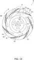
FIG. 13 is a view seen in the direction of arrow A inFIG. 12 (with part of the shroud being excluded). -
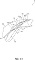
FIG. 14 is an enlarged view of portion C inFIG. 13 . -
FIG. 15 is a view showing a cross section along line II-II ofFIG. 14 . -
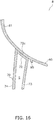
FIG. 16 is a view showing a cross section along line III-III ofFIG. 14 . - An embodiment of a centrifugal fan impeller pertaining to the present invention will be described below on the basis of the drawings. It will be noted that the specific configurations of the centrifugal fan impeller pertaining to the present invention are not limited to those in the following embodiment and example modification and can be changed in a range that does not depart from the spirit of the invention.
- In
FIG. 1 is shown an external perspective view (with a ceiling being omitted) of anair conditioning apparatus 1 in which acentrifugal fan 4 equipped with animpeller 8 pertaining to an embodiment of the present invention is employed. Theair conditioning apparatus 1 here is an air conditioning apparatus installed in a ceiling and mainly has acasing 2, which houses various constituent devices inside, and adecorative panel 3, which is disposed on the lower side of thecasing 2. - The
casing 2 of theair conditioning apparatus 1 is a box-like member whose undersurface is open. As shown inFIG. 2 (a general side sectional view of the air conditioning apparatus 1), thecasing 2 is inserted and disposed in an opening formed in a ceiling of an air-conditioned room. Additionally, thedecorative panel 3 has anair inlet 3a, which is disposed in the substantial center of thedecorative panel 3 in order to suck the air in the air-conditioned room into thecasing 2, andair outlets 3b, which are disposed so as to surround the outer periphery of theair inlet 3a in order to blow the air out from thecasing 2 to the air-conditioned room. Thedecorative panel 3 is disposed in such a way as to be fitted into the opening in the ceiling. - Mainly disposed inside the
casing 2 are acentrifugal fan 4 that sucks the air in the air-conditioned room into thecasing 2 through theair inlet 3a in thedecorative panel 3 and blows the air out in an outer peripheral direction, aheat exchanger 5 that surrounds the outer periphery of thecentrifugal fan 4, and a bell mouth 6 for guiding the air sucked in from theair inlet 3a to thecentrifugal fan 4. Thecentrifugal fan 4 has a fan motor 7, which is provided in the substantial center of atop plate 2a of thecasing 2, and theimpeller 8, which is coupled to and driven to rotate by the fan motor 7. - It will be noted that the
air conditioning apparatus 1 provided with thecentrifugal fan 4 is not limited to an apparatus installed in a ceiling and may also be another type. Furthermore, the configuration of theimpeller 8 will be described later. - Next, the configuration of the
impeller 8 will be described usingFIG. 3 to FIG. 11 . Here,FIG. 3 is an external perspective view of theimpeller 8.FIG. 4 is a view seen in the direction of arrow A inFIG. 3 (with part of ashroud 80 being excluded).FIG. 5 is a view seen in the direction of arrow B inFIG. 3 (with part of amain plate 60 being excluded).FIG. 6 is an enlarged view of portion C inFIG. 4 .FIG. 7 is an enlarged view of portion D inFIG. 5 .FIG. 8 is a view showing a cross section along line IV-IV ofFIG. 7 .FIG. 9 is a view showing a cross section along line I-I ofFIG. 6 .FIG. 10 is a view showing a cross section along line II-II ofFIG. 6 .FIG. 11 is a view showing a cross section along line III-III ofFIG. 6 . - The
impeller 8 mainly has a disc-shapedmain plate 60 that is coupled to the fan motor 7, plural (here, seven)blades 70 that are annularly disposed around a rotational axis O of themain plate 60 on the side of themain plate 60 opposite the fan motor 7 side, and anannular shroud 80 that is disposed so as to sandwich theplural blades 70 between itself and themain plate 60 in the direction of the rotational axis O. Here, R denotes the rotational direction of theimpeller 8. - The
main plate 60 is a member made of resin having a substantially circular truncated cone-shapedhub portion 61 formed in the central portion thereof so as to project toward theair inlet 3a side. Formed in thehub portion 61 are, for example, plural (here, three) cooling-use air holes 62 being long holes formed adjacent to each other on a circle concentric with themain plate 60. Furthermore, the section of themain plate 60 on the outer peripheral side of thehub portion 61 is an annular flat plate-likeflat plate portion 63. - The
shroud 80 is a bell-shaped member made of resin that projects while curving toward theair inlet 3a side heading from its outer peripheral portion toward an opening in its central portion. Here, the curved plate-like section of theshroud 80 that curves in such a way that its diameter becomes smaller heading away from theblades 70 in the rotational axis O direction (i.e., heading toward theair inlet 3a side) is a shroudcurved plate portion 81. - The
blades 70 here are members made of resin molded separately from themain plate 60 and theshroud 80. End portions of theblades 70 on one side in the rotational axis O direction are main plate-side bladeaxial end portions 71 disposed opposing themain plate 60 and are secured to themain plate 60. End portions of theblades 70 on the other side in the rotational axis O direction are shroud-side bladeaxial end portions 72 disposed opposing theshroud 80 and are secured to theshroud 80. Here, theblades 70 have a shape where, when theimpeller 8 is viewed along the rotational axis O direction, the main plate-side bladeaxial end portions 71 are rearwardly inclined beyond the shroud-side bladeaxial end portions 72. Furthermore, theblades 70 are hollow blades mainly havingblade bodies 73 and blade covers 74, and the blade covers 74 are attached to theblade bodies 73 by being fitted therein and form hollow spaces S between themselves and theblade bodies 73, whereby theblades 70 are reduced in weight. It will be noted that the hollowing of theblades 70 may also be accomplished by blow molding, for example, rather than being accomplished by a structure where the twomembers centrifugal fan 4 are formed in the trailing edge portions of theblades 70, but in a case where sufficient performance can be obtained without forming the concavo-convex shapes, it is not invariably necessary to form the concavo-convex shapes. Furthermore, here, theblades 70 are members separate from themain plate 60 and theshroud 80, but theblades 70 are not limited to this and may also be molded integrally with themain plate 60. In this case, it suffices simply to secure theblades 70 to theshroud 80. - Additionally, the securing of the main plate-side blade
axial end portions 71 of theblades 70 to themain plate 60 is performed by welding the main plate-side bladeaxial end portions 71 and themain plate 60 to each other, and the welded sections form main plate-side weldedportions 8a. Here, as the method of welding theblades 70 to themain plate 60, a method that applies ultrasonic waves to theflat plate portion 63 of themain plate 60 andflat surfaces 71a of the main plate-side bladeaxial end portions 71 of theblades 70 to thereby weld theflat plate portion 63 and theflat surfaces 71a to each other (ultrasonic welding) is employed. However, the method of welding theblades 70 to themain plate 60 is not limited to ultrasonic welding so long as it is a method of welding theflat plate portion 63 and theflat surfaces 71a to each other, and another welding method may also be employed, such as, for example, employing a method that applies a laser to theflat plate portion 63 and theflat surfaces 71a to thereby weld theflat plate portion 63 and theflat surfaces 71a to each other (laser welding). - Furthermore, the securing of the shroud-side blade
axial end portions 72 of theblades 70 to theshroud 80 is performed by welding the shroud-side bladeaxial end portions 72 and theshroud 80 to each other, and the welded sections form shroud-side weldedportions 8b. Here, flat plate-like shroudflat plate portions 82 are formed in theshroud 80 in correspondence to just parts of the sections of theshroud 80 that oppose the shroud-side bladeaxial end portions 72, and the shroud-side weldedportions 8b are disposed in the shroudflat plate portions 82. That is, theshroud 80 is largely configured by the curved plate-like shroud curvedplate portion 81 curved in such a way that its diameter becomes smaller heading away from theblades 70 in the rotational axis O direction, but the flat plate-likeflat plate portions 82 perpendicular to the rotational axis O direction are formed in just parts of the sections of the shroud curvedplate portion 81 corresponding to the shroud-side bladeaxial end portions 72. Additionally, in the shroud-side bladeaxial end portions 72 of theblades 70 are formed bladeflat surfaces 72a being flat surfaces that follow the shroudflat plate portions 82 and blade curvedsurfaces plate portion 81. The bladeflat surfaces 72a oppose the shroudflat plate portions 82 and, like the shroudflat plate portions 82, are surfaces perpendicular to the rotational axis O direction. Consequently, the bladeflat surfaces 72a of the shroud-side bladeaxial end portions 72 oppose the shroudflat plate portions 82, and the blade curvedsurfaces axial end portions 72 oppose the shroud curvedplate portion 81, whereby the shroud-side bladeaxial end portions 72 entirely follow theshroud 80. The shroud-side weldedportions 8b are formed as a result of the bladeflat surfaces 72a and the shroudflat plate portions 82 being welded to each other. Here, as the method of welding theblades 70 to theshroud 80, a method that applies ultrasonic waves to the shroudflat plate portions 82 of theshroud 80 and the bladeflat surfaces 72a of the shroud-side bladeaxial end portions 72 of theblades 70 to thereby weld the shroudflat plate portions 82 and the bladeflat surfaces 72a to each other (ultrasonic welding) is employed. However, the method of welding theblades 70 to theshroud 80 is not limited to ultrasonic welding so long as it is a method of welding the shroudflat plate portions 82 and the bladeflat surfaces 72a to each other, and another welding method may also be employed, such as, for example, employing a method that applies a laser to the shroudflat plate portions 82 and the bladeflat surfaces 72a to thereby weld the shroudflat plate portions 82 and the bladeflat surfaces 72a to each other (laser welding). - Here, the blade
flat surfaces 72a are disposed so as to correspond to the vicinities of chord length direction centers of the shroud-side bladeaxial end portions 72. For this reason, the shroudflat plate portions 82 are also disposed in the vicinities of the chord length direction centers of the shroud-side bladeaxial end portions 72. Additionally, of the blade curvedsurfaces flat surfaces 72a-are leading edge-side blade curvedsurfaces 72b, and of the blade curvedsurfaces flat surfaces 72a-are trailing edge-side blade curvedsurfaces 72c. - Furthermore,
shroud step portions 83 that interconnect the shroudflat plate portions 82 and the shroud curvedplate portion 81 are formed in theshroud 80 on the peripheral sections of the shroudflat plate portions 82, and blade steppedportions 72d that can fit together with the shroud steppedportions 83 and interconnect the blade curvedsurfaces axial end portions 72 on the peripheral sections of the bladeflat surfaces 72a. Additionally, the blade stepped portions 77 are configured to fit together with the shroud steppedportions 83 in a state in which the shroudflat plate portions 82 and the bladeflat plate portions 72a lie on top of each other in the rotational axis O direction. That is, theblades 70 are positioned in predetermined positions on theshroud 80 because of the shroud steppedportions 83 and the blade steppedportions 72d. - The
impeller 8 of thecentrifugal fan 4 has the following characteristics in relation to the structure in the vicinity of the shroud-side weldedportions 8b formed between the shroud-side bladeaxial end portions 72 of theblades 70 and theshroud 80. - Here, as described above, the
shroud 80 has the curved plate-like shroud curvedplate portion 81 and the flat plate-like shroudflat plate portions 82 formed in correspondence to just parts of the sections of theshroud 80 that oppose the bladeaxial end portions 72. In the bladeaxial end portions 72 are formed the bladeflat surfaces 72a being flat surfaces that follow the shroudflat plate portions 82 and the blade curvedsurfaces plate portion 81. The weldedportions 8b resulting from the bladeflat surfaces 72a and the shroudflat plate portions 82 being welded to each other are formed between the bladeaxial end portions 72 and theshroud 80. That is, here, theimpeller 8 employs a structure where the sections at which theblades 70 and theshroud 80 oppose each other are largely left as a curved plate portion (the shroud curved plate portion 81) and curved surfaces (the blade curvedsurfaces flat surfaces 72a) are formed, and welded to each other, in just parts of the sections at which theblades 70 and theshroud 80 oppose each other. For this reason, here, in comparison to a case where the impeller employs a conventional structure where staircase shapes are formed in the blades and the shroud and welded to each other, it becomes difficult for the airflow in the vicinity of theshroud 80 to be obstructed. - Because of this, here, the airflow in the vicinity of the
shroud 80 can be improved to thereby achieve an improvement in blowing performance and a reduction in blowing noise. - Here, as described above, in employing a structure where the flat plate portions (the shroud flat plate portions 82) and the flat surfaces (the blade
flat surfaces 72a) are formed, and welded to each other, in just parts of the sections at which theblades 70 and theshroud 80 oppose each other, the welding of theblades 70 and theshroud 80 to each other is performed at the sections in the vicinities of the chord length direction centers of the bladeaxial end portions 72. For this reason, in comparison to a case where the welding of theblades 70 and theshroud 80 to each other is performed at the leading edge-side sections and/or the trailing edge-side sections of the bladeaxial end portions 72, robust welding becomes possible. - Because of this, here, the area of the blade
flat surfaces 72a required for welding and the area of the shroudflat plate portions 82 corresponding thereto can be reduced. - In employing a structure where, as described above, the flat plate portions (the shroud flat plate portions 82) and the flat surfaces (the blade
flat surfaces 72a) are formed, and welded to each other, in just parts of the sections at which theblades 70 and theshroud 80 oppose each other, when the welding of theblades 70 and theshroud 80 to each other is performed at the sections in the vicinities of the chord length direction centers of the blade axial end portions (seeFIG. 9 ), there is the concern that gaps will form between the leading edge-side sections of the shroud-side bladeaxial end portions 72 and the shroud curvedplate portion 81 because of, for example, strain during the molding of theblades 70 and the shroud 80 (seeFIG. 10 ). Additionally, such gaps at the leading edge-side sections of the shroud-side bladeaxial end portions 72 cause a disruption in the airflow heading through the opening in the central portion of theshroud 80 toward the leading edges of theblades 70, so there is the concern that this will increase blowing noise. - Thus, here, as shown in
FIG. 12 to FIG. 15 , leading edge-side recessedportions 84, into which the leading edge-side sections of the shroud-side bladeaxial end portions 72 are insertable, are formed in theshroud 80. For this reason, disruption of the airflow caused by gaps between the leading edge-side sections of the shroud-side bladeaxial end portions 72 and the shroud curvedplate portion 81 can be curbed. Here, when the leading edge-side recessedportions 84 are formed in theshroud 80, there is an adverse impact on blowing performance and blowing noise, but here, by forming the leading edge-side recessedportions 84 in such a way as to follow the blade curvedsurfaces 72b, the adverse impact on blowing performance and blowing noise caused by the leading edge-side recessedportions 84 is curbed. - Because of this, here, disruption of the airflow caused by gaps between the leading edge-side sections of the shroud-side blade
axial end portions 72 and the shroud curvedplate portion 81 can be curbed to thereby curb an increase in blowing noise caused by the gaps. - In particular, here, as shown in
FIG. 15 , the leading edge-side recessedportions 84 project from the shroud curvedplate portion 81 toward the side opposite theblade 70 side in the rotational axis O direction in such a way as to form curved plate portions parallel to the shroud curvedplate portion 81. - Because of this, here, the adverse impact on blowing performance and blowing noise caused by the leading edge-side recessed
portions 84 can be effectively curbed. - It will be noted that although it is not employed here, a seal material may be disposed between the leading edge-side sections of the shroud-side blade
axial end portions 72 and the leading edge-side recessedportions 84 in order to further enhance the effect of curbing disruption of the airflow caused by gaps between the leading edge-side sections of the shroud-side bladeaxial end portions 72 and the shroud curvedplate portion 81. Furthermore, in a case where it is possible to satisfy the blowing performance and the blowing noise required of theimpeller 8 without forming the leading edge-side recessedportions 84, it is alright not to form the leading edge-side recessedportions 84. - Furthermore, when the welding of the
blades 70 and theshroud 80 to each other is performed at the sections in the vicinities of the chord length direction centers of the blade axial end portions (seeFIG. 9 ), there is the concern that gaps will also form between the trailing edge-side sections of the shroud-sideaxial end portions 72 and the shroud curvedplate portion 81 because of, for example, strain during the molding of theblades 70 and theshroud 80. Additionally, such gaps at the trailing edge-side sections of the shroud-side bladeaxial end portions 72 cause some of the airflow heading along the positive pressure surfaces of theblades 70 from the leading edges to the trailing edges to leak midway from the positive pressure surface sides to the negative pressure surface sides, so there is the concern that this will reduce blowing performance. - Thus, here, as shown in
FIG. 12 to FIG. 14 andFIG. 16 , trailing edge-side raisedportions 85 are formed in theshroud 80 in such a way as to line the trailing edge-side sections of the shroud-side bladeaxial end portions 72. For this reason, leakage of the airflow caused by gaps between the trailing edge-side sections of the shroud-side bladeaxial end portions 72 and the shroud curvedplate portion 81 can be curbed. - Because of this, here, leakage of the airflow caused by gaps between the trailing edge-side sections of the shroud-side blade
axial end portions 72 and the shroud curvedplate portion 81 can be curbed to thereby curb a reduction in blowing performance caused by the gaps. - In particular, here, as shown in
FIG. 16 , the trailing edge-side raisedportions 85 are disposed in correspondence to just the positive pressure surface sides of the shroud-side bladeaxial end portions 72. - Because of this, here, leakage of the airflow caused by gaps between the trailing edge-side sections of the shroud-side blade
axial end portions 72 and the shroud curvedplate portion 81 can be effectively curbed. - It will be noted that in a case where it is possible to satisfy the blowing performance and the blowing noise required of the
impeller 8 without forming the trailing edge-side raisedportions 85, it is alright not to form the trailing edge-side raisedportions 85. - The present invention is widely applicable to a centrifugal fan impeller equipped with plural blades that are annularly disposed around a rotational axis and a main plate and a shroud that are disposed so as to sandwich the rotational axis direction sides of the blades, with blade axial end portions, which are end portions of the blades on one side in the rotational axis direction, and the shroud being welded to each other.
-
- 4
- Centrifugal Fan
- 8
- Impeller
- 8b
- Shroud-side Welded Portions
- 60
- Main Plate
- 70
- Blades
- 72
- Shroud-side Blade Axial End Portions
- 72a
- Blade Flat Surfaces
- 72b, 72c
- Blade Curved Surfaces
- 80
- Shroud
- 81
- Shroud Curved Plate Portion
- 82
- Shroud Flat Plate Portions
- 84
- Leading Edge-side Recessed Portions
- 85
- Trailing Edge-side Raised Portions
-
- Patent Document 1:
JP-A No. 2005-155510 - Patent Document 2:
JP-A No. 2015-86827
Claims (6)
- A centrifugal fan (4) impeller (8) comprising:plural blades (70) that are annularly disposed around a rotational axis; anda main plate (60) and a shroud (80) that are disposed so as to sandwich the rotational axis direction sides of the blades,with blade axial end portions (72), which are end portions of the blades on one side in the rotational axis direction, and the shroud being welded to each other,whereinthe shroud has a curved plate-like shroud curved plate portion (81) curved in such a way that its diameter becomes smaller heading away from the blades in the rotational axis direction and flat plate-like shroud flat plate portions (82) formed in correspondence to just parts of the sections of the shroud that oppose the blade axial end portions,in the blade axial end portions are formed blade flat surfaces (72a) being flat surfaces that follow the shroud flat plate portions and blade curved surfaces (72b, 72c) being curved surfaces that follow the shroud curved plate portion, andwelded portions (8b) resulting from the blade flat surfaces and the shroud flat plate portions being welded to each other are formed between the blade axial end portions and the shroud.
- The centrifugal fan impeller according to claim 1, wherein the blade flat surfaces are disposed in the vicinities of chord length direction centers of the blade axial end portions.
- The centrifugal fan impeller according to claim 2, wherein leading edge-side recessed portions (84), into which leading edge-side sections of the blade axial end portions are insertable, are formed in the shroud in such a way as to follow the blade curved surfaces.
- The centrifugal fan impeller according to claim 3, wherein the leading edge-side recessed portions project from the shroud curved plate portion in such a way as to form curved plate portions parallel to the shroud curved plate portion.
- The centrifugal fan impeller according to any one of claims 2 to 4, wherein trailing edge-side raised portions (85) are formed in the shroud in such a way as to line trailing edge-side sections of the blade axial end portions.
- The centrifugal fan impeller according to claim 5, wherein the trailing edge-side raised portions are disposed in correspondence to just positive pressure surface sides of the blade axial end portions.
Applications Claiming Priority (2)
| Application Number | Priority Date | Filing Date | Title |
|---|---|---|---|
| JP2016007181A JP6314998B2 (en) | 2016-01-18 | 2016-01-18 | Centrifugal fan impeller |
| PCT/JP2017/001105 WO2017126444A1 (en) | 2016-01-18 | 2017-01-13 | Centrifugal fan impeller |
Publications (3)
| Publication Number | Publication Date |
|---|---|
| EP3406910A1 true EP3406910A1 (en) | 2018-11-28 |
| EP3406910A4 EP3406910A4 (en) | 2019-01-02 |
| EP3406910B1 EP3406910B1 (en) | 2019-10-16 |
Family
ID=59361620
Family Applications (1)
| Application Number | Title | Priority Date | Filing Date |
|---|---|---|---|
| EP17741322.6A Active EP3406910B1 (en) | 2016-01-18 | 2017-01-13 | Centrifugal fan impeller |
Country Status (5)
| Country | Link |
|---|---|
| EP (1) | EP3406910B1 (en) |
| JP (1) | JP6314998B2 (en) |
| CN (1) | CN108474389B (en) |
| ES (1) | ES2765859T3 (en) |
| WO (1) | WO2017126444A1 (en) |
Families Citing this family (4)
| Publication number | Priority date | Publication date | Assignee | Title |
|---|---|---|---|---|
| DE102016111830A1 (en) * | 2016-06-28 | 2017-12-28 | Ebm-Papst Mulfingen Gmbh & Co. Kg | Blower wheel and impeller |
| EP3647603A1 (en) | 2018-10-31 | 2020-05-06 | Carrier Corporation | Arrangement of centrifugal impeller of a fan for reducing noise |
| CN112824685B (en) * | 2019-11-21 | 2022-08-09 | 泛仕达机电股份有限公司 | Centrifugal impeller with efficiency improving device |
| JP7722865B2 (en) * | 2020-12-25 | 2025-08-13 | 三星電子株式会社 | Centrifugal fans and indoor units for air conditioners |
Family Cites Families (13)
| Publication number | Priority date | Publication date | Assignee | Title |
|---|---|---|---|---|
| DE3605852A1 (en) * | 1986-02-22 | 1987-08-27 | Gebhardt Gmbh Wilhelm | Impeller for a radial fan |
| JPH0237296U (en) * | 1988-09-05 | 1990-03-12 | ||
| JP3092554B2 (en) * | 1997-09-30 | 2000-09-25 | ダイキン工業株式会社 | Centrifugal blower, method for manufacturing the same, and air conditioner equipped with the centrifugal blower |
| JP3391318B2 (en) * | 1999-11-16 | 2003-03-31 | ダイキン工業株式会社 | Centrifugal fan and air conditioner equipped with the fan |
| JP4432474B2 (en) * | 2003-11-27 | 2010-03-17 | ダイキン工業株式会社 | Centrifugal blower impeller and centrifugal blower provided with the impeller |
| JP2006017063A (en) * | 2004-07-05 | 2006-01-19 | Matsushita Electric Ind Co Ltd | Blower |
| JP5007457B2 (en) * | 2005-10-31 | 2012-08-22 | 三菱電機株式会社 | Turbo fan |
| JP4902718B2 (en) * | 2009-10-07 | 2012-03-21 | 三菱電機株式会社 | Centrifugal blower and vacuum cleaner |
| JP6341637B2 (en) * | 2013-06-14 | 2018-06-13 | 三菱電機株式会社 | Manufacturing method of centrifugal blower |
| JP6001520B2 (en) * | 2013-11-01 | 2016-10-05 | 日清紡メカトロニクス株式会社 | Method for manufacturing turbofan |
| JP6056953B1 (en) * | 2015-12-28 | 2017-01-11 | ダイキン工業株式会社 | Centrifugal fan impeller manufacturing equipment |
| JP6056952B1 (en) * | 2015-12-28 | 2017-01-11 | ダイキン工業株式会社 | Centrifugal fan impeller and manufacturing method thereof |
| EP3399195B1 (en) * | 2015-12-28 | 2020-02-19 | Daikin Industries, Ltd. | Method and apparatus for manufacturing an impeller of a centrifugal fan |
-
2016
- 2016-01-18 JP JP2016007181A patent/JP6314998B2/en active Active
-
2017
- 2017-01-13 ES ES17741322T patent/ES2765859T3/en active Active
- 2017-01-13 WO PCT/JP2017/001105 patent/WO2017126444A1/en not_active Ceased
- 2017-01-13 CN CN201780006713.0A patent/CN108474389B/en active Active
- 2017-01-13 EP EP17741322.6A patent/EP3406910B1/en active Active
Also Published As
| Publication number | Publication date |
|---|---|
| EP3406910A4 (en) | 2019-01-02 |
| CN108474389B (en) | 2019-07-09 |
| BR112018013261A2 (en) | 2018-12-04 |
| JP6314998B2 (en) | 2018-04-25 |
| CN108474389A (en) | 2018-08-31 |
| JP2017129024A (en) | 2017-07-27 |
| ES2765859T3 (en) | 2020-06-11 |
| WO2017126444A1 (en) | 2017-07-27 |
| EP3406910B1 (en) | 2019-10-16 |
Similar Documents
| Publication | Publication Date | Title |
|---|---|---|
| KR101876030B1 (en) | Blower with noise reduced and wind induced structure | |
| CN103946556B (en) | Outdoor cooling unit for vehicle air conditioner | |
| JP5728209B2 (en) | Centrifugal fan | |
| CN101660535A (en) | Centrifugal fan and air fluid machinery using the same | |
| US20160245298A1 (en) | Centrifugal fan and air conditioner provided with the same | |
| EP3406910B1 (en) | Centrifugal fan impeller | |
| CN105051374B (en) | Air-blast device | |
| JP2012207600A (en) | Centrifugal fan | |
| US20070201976A1 (en) | Impeller Of Multiblade Fan And Multiblade Fan Having The Same | |
| CN204783822U (en) | Centrifugal aerator | |
| ITMI20000466U1 (en) | CENTRIFUGAL FAN | |
| JP2006077631A (en) | Centrifugal blower impeller | |
| JP2014139412A (en) | Multiblade centrifugal fan and multiblade centrifugal blower including the same | |
| JP4512352B2 (en) | Pipe fan | |
| EP1411248B1 (en) | Impeller for centrifugal fan and centrifugal fan equipped with the same | |
| JP4857495B2 (en) | Impeller of multi-blade fan and multi-blade fan equipped with the impeller | |
| KR102104513B1 (en) | Centrifugal fan for air-blowing | |
| CN108474388A (en) | Centrifugal fan and air conditioner with centrifugal fan | |
| KR101626488B1 (en) | Centrifugal fan | |
| JP2012202263A (en) | Impeller for sirocco fan and sirocco fan | |
| CN115917159A (en) | Multi-blade impeller and centrifugal blower | |
| JP5269025B2 (en) | Centrifugal fan and air conditioner indoor unit equipped with the same | |
| JP2014122580A (en) | Multiblade centrifugal fan and multiblade centrifugal air blower including the same | |
| JP4736253B2 (en) | Impeller of multi-blade fan and multi-blade fan equipped with the impeller | |
| JP2006017037A (en) | Impeller of multiblade blower |
Legal Events
| Date | Code | Title | Description |
|---|---|---|---|
| STAA | Information on the status of an ep patent application or granted ep patent |
Free format text: STATUS: THE INTERNATIONAL PUBLICATION HAS BEEN MADE |
|
| PUAI | Public reference made under article 153(3) epc to a published international application that has entered the european phase |
Free format text: ORIGINAL CODE: 0009012 |
|
| STAA | Information on the status of an ep patent application or granted ep patent |
Free format text: STATUS: REQUEST FOR EXAMINATION WAS MADE |
|
| 17P | Request for examination filed |
Effective date: 20180810 |
|
| AK | Designated contracting states |
Kind code of ref document: A1 Designated state(s): AL AT BE BG CH CY CZ DE DK EE ES FI FR GB GR HR HU IE IS IT LI LT LU LV MC MK MT NL NO PL PT RO RS SE SI SK SM TR |
|
| AX | Request for extension of the european patent |
Extension state: BA ME |
|
| A4 | Supplementary search report drawn up and despatched |
Effective date: 20181205 |
|
| RIC1 | Information provided on ipc code assigned before grant |
Ipc: F04D 29/66 20060101ALI20181128BHEP Ipc: F04D 29/30 20060101ALI20181128BHEP Ipc: F04D 29/28 20060101AFI20181128BHEP |
|
| DAV | Request for validation of the european patent (deleted) | ||
| DAX | Request for extension of the european patent (deleted) | ||
| GRAP | Despatch of communication of intention to grant a patent |
Free format text: ORIGINAL CODE: EPIDOSNIGR1 |
|
| STAA | Information on the status of an ep patent application or granted ep patent |
Free format text: STATUS: GRANT OF PATENT IS INTENDED |
|
| INTG | Intention to grant announced |
Effective date: 20190621 |
|
| GRAS | Grant fee paid |
Free format text: ORIGINAL CODE: EPIDOSNIGR3 |
|
| GRAA | (expected) grant |
Free format text: ORIGINAL CODE: 0009210 |
|
| STAA | Information on the status of an ep patent application or granted ep patent |
Free format text: STATUS: THE PATENT HAS BEEN GRANTED |
|
| AK | Designated contracting states |
Kind code of ref document: B1 Designated state(s): AL AT BE BG CH CY CZ DE DK EE ES FI FR GB GR HR HU IE IS IT LI LT LU LV MC MK MT NL NO PL PT RO RS SE SI SK SM TR |
|
| REG | Reference to a national code |
Ref country code: GB Ref legal event code: FG4D |
|
| REG | Reference to a national code |
Ref country code: CH Ref legal event code: EP |
|
| REG | Reference to a national code |
Ref country code: DE Ref legal event code: R096 Ref document number: 602017007911 Country of ref document: DE |
|
| REG | Reference to a national code |
Ref country code: IE Ref legal event code: FG4D |
|
| REG | Reference to a national code |
Ref country code: AT Ref legal event code: REF Ref document number: 1191549 Country of ref document: AT Kind code of ref document: T Effective date: 20191115 |
|
| REG | Reference to a national code |
Ref country code: NL Ref legal event code: MP Effective date: 20191016 |
|
| REG | Reference to a national code |
Ref country code: LT Ref legal event code: MG4D |
|
| REG | Reference to a national code |
Ref country code: AT Ref legal event code: MK05 Ref document number: 1191549 Country of ref document: AT Kind code of ref document: T Effective date: 20191016 |
|
| PG25 | Lapsed in a contracting state [announced via postgrant information from national office to epo] |
Ref country code: PT Free format text: LAPSE BECAUSE OF FAILURE TO SUBMIT A TRANSLATION OF THE DESCRIPTION OR TO PAY THE FEE WITHIN THE PRESCRIBED TIME-LIMIT Effective date: 20200217 Ref country code: FI Free format text: LAPSE BECAUSE OF FAILURE TO SUBMIT A TRANSLATION OF THE DESCRIPTION OR TO PAY THE FEE WITHIN THE PRESCRIBED TIME-LIMIT Effective date: 20191016 Ref country code: NO Free format text: LAPSE BECAUSE OF FAILURE TO SUBMIT A TRANSLATION OF THE DESCRIPTION OR TO PAY THE FEE WITHIN THE PRESCRIBED TIME-LIMIT Effective date: 20200116 Ref country code: GR Free format text: LAPSE BECAUSE OF FAILURE TO SUBMIT A TRANSLATION OF THE DESCRIPTION OR TO PAY THE FEE WITHIN THE PRESCRIBED TIME-LIMIT Effective date: 20200117 Ref country code: LT Free format text: LAPSE BECAUSE OF FAILURE TO SUBMIT A TRANSLATION OF THE DESCRIPTION OR TO PAY THE FEE WITHIN THE PRESCRIBED TIME-LIMIT Effective date: 20191016 Ref country code: PL Free format text: LAPSE BECAUSE OF FAILURE TO SUBMIT A TRANSLATION OF THE DESCRIPTION OR TO PAY THE FEE WITHIN THE PRESCRIBED TIME-LIMIT Effective date: 20191016 Ref country code: SE Free format text: LAPSE BECAUSE OF FAILURE TO SUBMIT A TRANSLATION OF THE DESCRIPTION OR TO PAY THE FEE WITHIN THE PRESCRIBED TIME-LIMIT Effective date: 20191016 Ref country code: AT Free format text: LAPSE BECAUSE OF FAILURE TO SUBMIT A TRANSLATION OF THE DESCRIPTION OR TO PAY THE FEE WITHIN THE PRESCRIBED TIME-LIMIT Effective date: 20191016 Ref country code: LV Free format text: LAPSE BECAUSE OF FAILURE TO SUBMIT A TRANSLATION OF THE DESCRIPTION OR TO PAY THE FEE WITHIN THE PRESCRIBED TIME-LIMIT Effective date: 20191016 Ref country code: NL Free format text: LAPSE BECAUSE OF FAILURE TO SUBMIT A TRANSLATION OF THE DESCRIPTION OR TO PAY THE FEE WITHIN THE PRESCRIBED TIME-LIMIT Effective date: 20191016 Ref country code: BG Free format text: LAPSE BECAUSE OF FAILURE TO SUBMIT A TRANSLATION OF THE DESCRIPTION OR TO PAY THE FEE WITHIN THE PRESCRIBED TIME-LIMIT Effective date: 20200116 |
|
| PG25 | Lapsed in a contracting state [announced via postgrant information from national office to epo] |
Ref country code: IS Free format text: LAPSE BECAUSE OF FAILURE TO SUBMIT A TRANSLATION OF THE DESCRIPTION OR TO PAY THE FEE WITHIN THE PRESCRIBED TIME-LIMIT Effective date: 20200224 Ref country code: HR Free format text: LAPSE BECAUSE OF FAILURE TO SUBMIT A TRANSLATION OF THE DESCRIPTION OR TO PAY THE FEE WITHIN THE PRESCRIBED TIME-LIMIT Effective date: 20191016 Ref country code: RS Free format text: LAPSE BECAUSE OF FAILURE TO SUBMIT A TRANSLATION OF THE DESCRIPTION OR TO PAY THE FEE WITHIN THE PRESCRIBED TIME-LIMIT Effective date: 20191016 |
|
| REG | Reference to a national code |
Ref country code: ES Ref legal event code: FG2A Ref document number: 2765859 Country of ref document: ES Kind code of ref document: T3 Effective date: 20200611 |
|
| PG25 | Lapsed in a contracting state [announced via postgrant information from national office to epo] |
Ref country code: AL Free format text: LAPSE BECAUSE OF FAILURE TO SUBMIT A TRANSLATION OF THE DESCRIPTION OR TO PAY THE FEE WITHIN THE PRESCRIBED TIME-LIMIT Effective date: 20191016 |
|
| REG | Reference to a national code |
Ref country code: DE Ref legal event code: R097 Ref document number: 602017007911 Country of ref document: DE |
|
| PG2D | Information on lapse in contracting state deleted |
Ref country code: IS |
|
| PG25 | Lapsed in a contracting state [announced via postgrant information from national office to epo] |
Ref country code: DK Free format text: LAPSE BECAUSE OF FAILURE TO SUBMIT A TRANSLATION OF THE DESCRIPTION OR TO PAY THE FEE WITHIN THE PRESCRIBED TIME-LIMIT Effective date: 20191016 Ref country code: EE Free format text: LAPSE BECAUSE OF FAILURE TO SUBMIT A TRANSLATION OF THE DESCRIPTION OR TO PAY THE FEE WITHIN THE PRESCRIBED TIME-LIMIT Effective date: 20191016 Ref country code: CZ Free format text: LAPSE BECAUSE OF FAILURE TO SUBMIT A TRANSLATION OF THE DESCRIPTION OR TO PAY THE FEE WITHIN THE PRESCRIBED TIME-LIMIT Effective date: 20191016 Ref country code: RO Free format text: LAPSE BECAUSE OF FAILURE TO SUBMIT A TRANSLATION OF THE DESCRIPTION OR TO PAY THE FEE WITHIN THE PRESCRIBED TIME-LIMIT Effective date: 20191016 Ref country code: IS Free format text: LAPSE BECAUSE OF FAILURE TO SUBMIT A TRANSLATION OF THE DESCRIPTION OR TO PAY THE FEE WITHIN THE PRESCRIBED TIME-LIMIT Effective date: 20200216 |
|
| PLBE | No opposition filed within time limit |
Free format text: ORIGINAL CODE: 0009261 |
|
| STAA | Information on the status of an ep patent application or granted ep patent |
Free format text: STATUS: NO OPPOSITION FILED WITHIN TIME LIMIT |
|
| PG25 | Lapsed in a contracting state [announced via postgrant information from national office to epo] |
Ref country code: MC Free format text: LAPSE BECAUSE OF FAILURE TO SUBMIT A TRANSLATION OF THE DESCRIPTION OR TO PAY THE FEE WITHIN THE PRESCRIBED TIME-LIMIT Effective date: 20191016 Ref country code: SM Free format text: LAPSE BECAUSE OF FAILURE TO SUBMIT A TRANSLATION OF THE DESCRIPTION OR TO PAY THE FEE WITHIN THE PRESCRIBED TIME-LIMIT Effective date: 20191016 Ref country code: SK Free format text: LAPSE BECAUSE OF FAILURE TO SUBMIT A TRANSLATION OF THE DESCRIPTION OR TO PAY THE FEE WITHIN THE PRESCRIBED TIME-LIMIT Effective date: 20191016 |
|
| REG | Reference to a national code |
Ref country code: CH Ref legal event code: PL |
|
| 26N | No opposition filed |
Effective date: 20200717 |
|
| REG | Reference to a national code |
Ref country code: BE Ref legal event code: MM Effective date: 20200131 |
|
| PG25 | Lapsed in a contracting state [announced via postgrant information from national office to epo] |
Ref country code: LU Free format text: LAPSE BECAUSE OF NON-PAYMENT OF DUE FEES Effective date: 20200113 |
|
| PG25 | Lapsed in a contracting state [announced via postgrant information from national office to epo] |
Ref country code: LI Free format text: LAPSE BECAUSE OF NON-PAYMENT OF DUE FEES Effective date: 20200131 Ref country code: CH Free format text: LAPSE BECAUSE OF NON-PAYMENT OF DUE FEES Effective date: 20200131 Ref country code: BE Free format text: LAPSE BECAUSE OF NON-PAYMENT OF DUE FEES Effective date: 20200131 Ref country code: SI Free format text: LAPSE BECAUSE OF FAILURE TO SUBMIT A TRANSLATION OF THE DESCRIPTION OR TO PAY THE FEE WITHIN THE PRESCRIBED TIME-LIMIT Effective date: 20191016 |
|
| PG25 | Lapsed in a contracting state [announced via postgrant information from national office to epo] |
Ref country code: IE Free format text: LAPSE BECAUSE OF NON-PAYMENT OF DUE FEES Effective date: 20200113 |
|
| PG25 | Lapsed in a contracting state [announced via postgrant information from national office to epo] |
Ref country code: MT Free format text: LAPSE BECAUSE OF FAILURE TO SUBMIT A TRANSLATION OF THE DESCRIPTION OR TO PAY THE FEE WITHIN THE PRESCRIBED TIME-LIMIT Effective date: 20191016 Ref country code: CY Free format text: LAPSE BECAUSE OF FAILURE TO SUBMIT A TRANSLATION OF THE DESCRIPTION OR TO PAY THE FEE WITHIN THE PRESCRIBED TIME-LIMIT Effective date: 20191016 |
|
| PG25 | Lapsed in a contracting state [announced via postgrant information from national office to epo] |
Ref country code: MK Free format text: LAPSE BECAUSE OF FAILURE TO SUBMIT A TRANSLATION OF THE DESCRIPTION OR TO PAY THE FEE WITHIN THE PRESCRIBED TIME-LIMIT Effective date: 20191016 |
|
| P01 | Opt-out of the competence of the unified patent court (upc) registered |
Effective date: 20230525 |
|
| PGFP | Annual fee paid to national office [announced via postgrant information from national office to epo] |
Ref country code: GB Payment date: 20251127 Year of fee payment: 10 |
|
| PGFP | Annual fee paid to national office [announced via postgrant information from national office to epo] |
Ref country code: FR Payment date: 20251128 Year of fee payment: 10 |
|
| PGFP | Annual fee paid to national office [announced via postgrant information from national office to epo] |
Ref country code: ES Payment date: 20260203 Year of fee payment: 10 |
|
| PGFP | Annual fee paid to national office [announced via postgrant information from national office to epo] |
Ref country code: DE Payment date: 20251203 Year of fee payment: 10 |
|
| PGFP | Annual fee paid to national office [announced via postgrant information from national office to epo] |
Ref country code: IT Payment date: 20251219 Year of fee payment: 10 |
|
| PGFP | Annual fee paid to national office [announced via postgrant information from national office to epo] |
Ref country code: TR Payment date: 20260112 Year of fee payment: 10 |