EP3406898A1 - Gondelkomponente für eine windenergieanlage und verfahren zum montieren einer gondelkomponente - Google Patents
Gondelkomponente für eine windenergieanlage und verfahren zum montieren einer gondelkomponente Download PDFInfo
- Publication number
- EP3406898A1 EP3406898A1 EP18172806.4A EP18172806A EP3406898A1 EP 3406898 A1 EP3406898 A1 EP 3406898A1 EP 18172806 A EP18172806 A EP 18172806A EP 3406898 A1 EP3406898 A1 EP 3406898A1
- Authority
- EP
- European Patent Office
- Prior art keywords
- module
- electric module
- nacelle
- component
- generator
- Prior art date
- Legal status (The legal status is an assumption and is not a legal conclusion. Google has not performed a legal analysis and makes no representation as to the accuracy of the status listed.)
- Granted
Links
Images





Classifications
-
- F—MECHANICAL ENGINEERING; LIGHTING; HEATING; WEAPONS; BLASTING
- F03—MACHINES OR ENGINES FOR LIQUIDS; WIND, SPRING, OR WEIGHT MOTORS; PRODUCING MECHANICAL POWER OR A REACTIVE PROPULSIVE THRUST, NOT OTHERWISE PROVIDED FOR
- F03D—WIND MOTORS
- F03D9/00—Adaptations of wind motors for special use; Combinations of wind motors with apparatus driven thereby; Wind motors specially adapted for installation in particular locations
- F03D9/20—Wind motors characterised by the driven apparatus
- F03D9/25—Wind motors characterised by the driven apparatus the apparatus being an electrical generator
-
- F—MECHANICAL ENGINEERING; LIGHTING; HEATING; WEAPONS; BLASTING
- F03—MACHINES OR ENGINES FOR LIQUIDS; WIND, SPRING, OR WEIGHT MOTORS; PRODUCING MECHANICAL POWER OR A REACTIVE PROPULSIVE THRUST, NOT OTHERWISE PROVIDED FOR
- F03D—WIND MOTORS
- F03D13/00—Assembly, mounting or commissioning of wind motors; Arrangements specially adapted for transporting wind motor components
- F03D13/10—Assembly of wind motors; Arrangements for erecting wind motors
-
- F—MECHANICAL ENGINEERING; LIGHTING; HEATING; WEAPONS; BLASTING
- F03—MACHINES OR ENGINES FOR LIQUIDS; WIND, SPRING, OR WEIGHT MOTORS; PRODUCING MECHANICAL POWER OR A REACTIVE PROPULSIVE THRUST, NOT OTHERWISE PROVIDED FOR
- F03D—WIND MOTORS
- F03D13/00—Assembly, mounting or commissioning of wind motors; Arrangements specially adapted for transporting wind motor components
- F03D13/20—Arrangements for mounting or supporting wind motors; Masts or towers for wind motors
-
- F—MECHANICAL ENGINEERING; LIGHTING; HEATING; WEAPONS; BLASTING
- F03—MACHINES OR ENGINES FOR LIQUIDS; WIND, SPRING, OR WEIGHT MOTORS; PRODUCING MECHANICAL POWER OR A REACTIVE PROPULSIVE THRUST, NOT OTHERWISE PROVIDED FOR
- F03D—WIND MOTORS
- F03D80/00—Details, components or accessories not provided for in groups F03D1/00 - F03D17/00
-
- F—MECHANICAL ENGINEERING; LIGHTING; HEATING; WEAPONS; BLASTING
- F03—MACHINES OR ENGINES FOR LIQUIDS; WIND, SPRING, OR WEIGHT MOTORS; PRODUCING MECHANICAL POWER OR A REACTIVE PROPULSIVE THRUST, NOT OTHERWISE PROVIDED FOR
- F03D—WIND MOTORS
- F03D80/00—Details, components or accessories not provided for in groups F03D1/00 - F03D17/00
- F03D80/50—Maintenance or repair
-
- F—MECHANICAL ENGINEERING; LIGHTING; HEATING; WEAPONS; BLASTING
- F03—MACHINES OR ENGINES FOR LIQUIDS; WIND, SPRING, OR WEIGHT MOTORS; PRODUCING MECHANICAL POWER OR A REACTIVE PROPULSIVE THRUST, NOT OTHERWISE PROVIDED FOR
- F03D—WIND MOTORS
- F03D80/00—Details, components or accessories not provided for in groups F03D1/00 - F03D17/00
- F03D80/80—Arrangement of components within nacelles or towers
-
- F—MECHANICAL ENGINEERING; LIGHTING; HEATING; WEAPONS; BLASTING
- F03—MACHINES OR ENGINES FOR LIQUIDS; WIND, SPRING, OR WEIGHT MOTORS; PRODUCING MECHANICAL POWER OR A REACTIVE PROPULSIVE THRUST, NOT OTHERWISE PROVIDED FOR
- F03D—WIND MOTORS
- F03D80/00—Details, components or accessories not provided for in groups F03D1/00 - F03D17/00
- F03D80/80—Arrangement of components within nacelles or towers
- F03D80/82—Arrangement of components within nacelles or towers of electrical components
-
- F—MECHANICAL ENGINEERING; LIGHTING; HEATING; WEAPONS; BLASTING
- F03—MACHINES OR ENGINES FOR LIQUIDS; WIND, SPRING, OR WEIGHT MOTORS; PRODUCING MECHANICAL POWER OR A REACTIVE PROPULSIVE THRUST, NOT OTHERWISE PROVIDED FOR
- F03D—WIND MOTORS
- F03D80/00—Details, components or accessories not provided for in groups F03D1/00 - F03D17/00
- F03D80/80—Arrangement of components within nacelles or towers
- F03D80/82—Arrangement of components within nacelles or towers of electrical components
- F03D80/85—Cabling
-
- F—MECHANICAL ENGINEERING; LIGHTING; HEATING; WEAPONS; BLASTING
- F05—INDEXING SCHEMES RELATING TO ENGINES OR PUMPS IN VARIOUS SUBCLASSES OF CLASSES F01-F04
- F05B—INDEXING SCHEME RELATING TO WIND, SPRING, WEIGHT, INERTIA OR LIKE MOTORS, TO MACHINES OR ENGINES FOR LIQUIDS COVERED BY SUBCLASSES F03B, F03D AND F03G
- F05B2240/00—Components
- F05B2240/10—Stators
- F05B2240/14—Casings, housings, nacelles, gondels or the like, protecting or supporting assemblies there within
-
- F—MECHANICAL ENGINEERING; LIGHTING; HEATING; WEAPONS; BLASTING
- F05—INDEXING SCHEMES RELATING TO ENGINES OR PUMPS IN VARIOUS SUBCLASSES OF CLASSES F01-F04
- F05B—INDEXING SCHEME RELATING TO WIND, SPRING, WEIGHT, INERTIA OR LIKE MOTORS, TO MACHINES OR ENGINES FOR LIQUIDS COVERED BY SUBCLASSES F03B, F03D AND F03G
- F05B2240/00—Components
- F05B2240/90—Mounting on supporting structures or systems
- F05B2240/91—Mounting on supporting structures or systems on a stationary structure
- F05B2240/916—Mounting on supporting structures or systems on a stationary structure with provision for hoisting onto the structure
-
- Y—GENERAL TAGGING OF NEW TECHNOLOGICAL DEVELOPMENTS; GENERAL TAGGING OF CROSS-SECTIONAL TECHNOLOGIES SPANNING OVER SEVERAL SECTIONS OF THE IPC; TECHNICAL SUBJECTS COVERED BY FORMER USPC CROSS-REFERENCE ART COLLECTIONS [XRACs] AND DIGESTS
- Y02—TECHNOLOGIES OR APPLICATIONS FOR MITIGATION OR ADAPTATION AGAINST CLIMATE CHANGE
- Y02E—REDUCTION OF GREENHOUSE GAS [GHG] EMISSIONS, RELATED TO ENERGY GENERATION, TRANSMISSION OR DISTRIBUTION
- Y02E10/00—Energy generation through renewable energy sources
- Y02E10/70—Wind energy
- Y02E10/72—Wind turbines with rotation axis in wind direction
-
- Y—GENERAL TAGGING OF NEW TECHNOLOGICAL DEVELOPMENTS; GENERAL TAGGING OF CROSS-SECTIONAL TECHNOLOGIES SPANNING OVER SEVERAL SECTIONS OF THE IPC; TECHNICAL SUBJECTS COVERED BY FORMER USPC CROSS-REFERENCE ART COLLECTIONS [XRACs] AND DIGESTS
- Y02—TECHNOLOGIES OR APPLICATIONS FOR MITIGATION OR ADAPTATION AGAINST CLIMATE CHANGE
- Y02E—REDUCTION OF GREENHOUSE GAS [GHG] EMISSIONS, RELATED TO ENERGY GENERATION, TRANSMISSION OR DISTRIBUTION
- Y02E10/00—Energy generation through renewable energy sources
- Y02E10/70—Wind energy
- Y02E10/728—Onshore wind turbines
Definitions
- the invention relates to a nacelle component for a wind turbine.
- the invention also relates to a method for mounting a nacelle component.
- a nacelle In wind turbines usually a nacelle is rotatably mounted on a tower.
- the nacelle carries a rotor which is connected to a generator via a rotor shaft.
- the rotor is rotated by the wind and drives the generator to generate electrical energy.
- the rotor By rotating the nacelle relative to the tower, the rotor can be aligned in the wind direction.
- the invention has for its object to present a nacelle component and a method for mounting a nacelle component, with which both the transport cost and the effort when building the wind turbine can be kept low.
- the nacelle component comprises a machine carrier module and an electric module.
- the machine carrier module and the electric module are each greater in longitudinal extent than in transverse extent.
- the machine frame module is aligned with its longitudinal extent along a vertical plane that extends through the rotor shaft axis.
- the electric module cuts in the assembled state with its longitudinal extent the vertical plane which extends through the rotor shaft axis.
- Composite state refers to the state in which the electric module is connected as intended to the machine carrier module.
- the available space can be effectively utilized, whereby the gondola can be composed of a reduced number of modules. Nevertheless, the modules are still dimensioned so that they can be easily transported.
- a favorable load distribution can be achieved by the transversely arranged electric module, because the components arranged on the electric module have a reduced distance from the axis of rotation of the nacelle. As a result, the load torque can be reduced.
- the machine carrier module and / or the electric module can have a rectangular shape or an approximated shape to a rectangle with respect to the plane defined by the longitudinal extent and the transverse extent.
- the longitudinal extent denotes the longer of the two axes and the transverse extent the shorter of the two axes.
- the longitudinal extent and transverse extent according to the invention relate to the smallest rectangle with which the relevant module can be surrounded.
- the transverse extent of the machine carrier module can be aligned horizontally.
- the longitudinal extent of the machine carrier module may extend parallel to the rotor shaft axis.
- the longitudinal extent of the electric module may extend in the horizontal direction and be aligned at a right angle to the rotor shaft axis.
- the transverse extent of the electric module may extend parallel to the rotor shaft axis.
- the transverse extent of the machine carrier module and the longitudinal extent of the electric module are preferably parallel to one another.
- the transverse extent of the electric module can be arranged as an extension of the longitudinal extent of the machine carrier module
- the machine carrier module may comprise a receptacle for a rotor shaft. By recording the direction of the rotor shaft axis can be defined.
- the receptacle can in particular be designed so that the rotor shaft extends in the assembled state parallel to the longitudinal extent of the machine carrier module.
- the receptacle may have bearing blocks on which one or more bearings for the rotor shaft can be mounted. It is also possible that the machine carrier module is brought into a preassembled state, in which a rotor shaft is supported by the machine carrier module and is mounted rotatably via bearings relative to the machine carrier module.
- the machine carrier module may include a receptacle for a transmission.
- the receptacle for the transmission may be separate from the receptacle for the rotor shaft. It is also possible that the machine carrier module comprises a common receptacle which carries the rotor shaft and the gearbox.
- the machine carrier module can be brought to a preassembled state in which the rotor shaft is rotatably supported relative to the engine support module and the transmission is mounted in a fixed position relative to the engine support module.
- the rotor shaft may be connected to the slow shaft of the transmission.
- the fast shaft may be disposed at an opposite end of the transmission and extending parallel to the longitudinal extent of the machine frame module.
- a rotor hub may be mounted.
- the rotor hub may have a plurality of connections for rotor blades, in particular three connections for rotor blades.
- the nacelle component according to the invention may comprise a transmission.
- the transmission can be connected via a transmission receptacle to the machine carrier module and / or to the electric module.
- a torque arm can be arranged, which counteracts a rotation of the transmission relative to the transmission mount.
- the torque arm may include a gearbox that is rigidly connected to the gearbox mount.
- a plurality of suspension elements may be disposed between the transmission frame and the transmission body, in particular at least three suspension elements, preferably at least five suspension elements, more preferably at least ten suspension elements.
- the suspension members may be resilient and, in particular, may be configured to permit resilient compensation movement between the transmission frame and the transmission body when a large torque is applied to the slow transmission shaft.
- the suspension elements may include a bearing pin.
- the bearing pin can extend parallel to the rotor shaft.
- the bearing pin can be rigidly connected to the Geretespant or with the gear body, while the connection between the bearing pin and the other element is designed to be elastic.
- the suspension elements may be arranged in a ring around the slow shaft of the transmission, in other words, the torque arm may comprise a plurality of suspension elements arranged at a matching distance from the slow shaft of the transmission.
- the suspension elements can be arranged evenly distributed over the circumference of the slow transmission shaft. It is also possible that the suspension elements are not evenly distributed over the circumference of the slow gear shaft.
- the torque arm includes a first peripheral portion provided with suspension members and a second peripheral portion free of suspension members.
- the first peripheral portion may extend for example over a circumferential angle between 180 ° and 270 °.
- the second peripheral portion may extend for example over a circumferential angle between 90 ° and 180 °.
- the suspension elements may be evenly distributed over the circumference.
- a transmission with a torque arm having one or more of said features has independent inventive content, even if the transmission is not used in the context of a nacelle component according to the invention.
- the transmission can be made narrower in the transverse direction than in a conventional torque arm, comprising two transversely projecting arms. This can be advantageous if replacement of the transmission is required.
- a compact gear can be pulled along the longitudinal axis of the machine carrier module in the electric module and rappeld from there to the base of the tower.
- a generator may be flanged to the fast shaft of the transmission, wherein the generator may be in the assembled state in the machine frame module;
- the machine carrier module may include a separate receptacle for the generator, a receptacle for the unit of generator and gear or a common receptacle for generator, gear and rotor shaft.
- the machine support module may be brought to a preassembled condition in which the rotor shaft is rotatably supported relative to the machine support module and connected via the transmission to the generator mounted in a fixed position relative to the machine support module.
- the machine carrier module may comprise a turntable, via which the machine carrier module can be connected to a tower of a wind energy plant.
- the axis of the turntable can coincide with an axis of rotation about which the machine support module or a nacelle, in which the machine support module is received, can be rotated relative to the tower.
- the axis of rotation may coincide with a central axis of the tower.
- the turntable may be formed as a connection for a bearing, so that a bearing ring on the turntable and the other bearing ring can be connected to the upper end of the tower. With a rotation of the bearing, the machine support module can be rotated relative to the tower.
- the bearing can be connected in the preassembled state with the machine carrier module.
- the electric module may comprise a receptacle for a generator in one embodiment of the nacelle component according to the invention.
- the electric module can be brought into a pre-assembled state, in which the generator is connected to the electric module. In the preassembled state, the electric module and the machine carrier module are not yet connected to each other.
- the generator may be arranged such that an input shaft of the generator extends parallel to the transverse extent of the electric module.
- the input shaft of the generator may be arranged off-center in the electric module, so that based on the longitudinal extent of the electric module, the distance to the one end of the electric module is smaller than the distance to the opposite end of the electric module.
- the distance to the right end of the electric module may be smaller than the distance to the left end of the electric module.
- the electric module can be brought into a pre-assembled state, in which the generator is connected to the electric module.
- the generator may extend over at least 40%, preferably at least 60%, further exhibiting at least 80% of the transverse extent of the electrical module.
- the electric module can be equipped with a receptacle for a converter.
- the electric module can be brought into a preassembled state in which a converter is connected to the electric module. It is possible to establish an electrical connection between the converter and the generator so that a test of faultless interaction between the converter and the generator (functional test) is possible.
- the converter may be spaced from the generator with respect to the longitudinal extent of the electric module. Based on the transverse dimension of the electric module, the inverter may overlap with the generator. If the generator is arranged eccentrically in the electric module, the converter can be arranged in the larger of the two sections of the electric module defined by the generator.
- the electric module may have a receptacle for a transformer.
- the electric module can be brought into a preassembled state in which a transformer is connected to the electric module.
- An electrical connection can be made between the transformer and the inverter, so that a test of the error-free interaction between the transformer, the inverter and / or the generator is possible.
- a medium voltage cable can be connected, which is designed to transmit the electrical power generated by the generator to a connection network.
- the medium voltage cable can be guided via the machine support module in the direction of a tower of the wind turbine.
- the transformer may be spaced from the generator with respect to the longitudinal extent of the electrical module. Based on the transverse extent of the electric module, the transformer may overlap with the generator. If the generator is arranged eccentrically in the electric module, then the transformer can be arranged in the smaller of the two sections of the electric module formed by the generator.
- the electric module may include a receptacle for one or more cabinets.
- the electric module can be brought into a pre-assembled state, in which one or more cabinets are connected to the electric module.
- a controller for the generator, the inverter and / or the transformer can be arranged in the control cabinets.
- An electrical connection can be made between the controller, the generator, the converter and / or the transformer so that a test of the faultless interaction of the relevant components is possible.
- the one or more cabinets may be spaced from the generator with respect to the longitudinal extent of the electric module. Based on the transverse extent of the electric module, the control cabinets can overlap with the generator. If the generator is arranged eccentrically in the electric module, then the Switch cabinets may be arranged in the larger of the two sections of the electric module formed by the generator. The control cabinets may be spaced from the inverter with respect to the transverse extent of the electric module. With regard to the longitudinal extent of the electrical module, the control cabinets can overlap with the inverter.
- the electric module can be equipped with a cooling system.
- the cooling system may be configured to cool the generator, the transformer and / or the inverter. It is also possible that the cooling system is designed to cool the transmission.
- a line may extend between the electric module and the machine carrier module, via which a cooling medium is exchanged between the cooling system and the transmission.
- the electric module may comprise a central frame which extends only over part of the longitudinal extent of the electric module.
- a side frame can connect, so that the central frame and the side frames extend in total over the longitudinal extent of the electric module.
- the central frame can be solid and carry heavier components of the electric module.
- the heavy components may include the generator.
- the side frames can be made less massive than the central frame and carry lighter components of the electric module.
- the lighter components may include the inverter, the transformer and / or cabinets.
- the electric module may comprise a frame part, within which a downwardly open breakthrough is formed.
- the breakthrough may be sized and arranged such that components of a nacelle disposed on a tower of a wind turbine discharge downwardly through the aperture can be, for example, for the purpose of maintenance or repair. These may be, for example, components which are connected to the machine carrier module and / or the electric module during operation of the wind energy plant.
- the frame part can enclose the breakthrough all around. It is also possible a frame part, which only partially surrounds the breakthrough.
- the frame member may include a first main carrier and a second main carrier, with the main carriers enclosing the aperture therebetween. The main carriers can extend in the transverse direction of the electric module.
- the opening can be arranged between the main carriers.
- the frame part coincides with the central support of the electric module.
- the electric module may comprise a component carrier.
- the component carrier may include receptacles for elements of the electrical module;
- the component carrier may comprise receptacles for the generator and / or the transformer.
- the component carrier may be connected to the frame part of the electric module. The attachment between the component carrier and the frame part may be detachable.
- An electric module with such a component carrier has independent inventive content, even without the electric module having further features of the nacelle component according to the invention.
- the component carrier In the connected state, the component carrier can be arranged below the frame part. Components connected to the component carrier can protrude into the opening of the frame part.
- the component carrier may be larger than the aperture such that components associated with the component carrier are disposed laterally adjacent to the aperture are when the component carrier is connected to the frame part.
- a component of the electrical module received by the component carrier may rest on the component carrier and / or be attached to the component carrier.
- the component may be attached to the frame part, a side frame or other elements of the electric module.
- the electric module can be brought into a preassembled state, in which the component carrier is connected to the frame part and in which one or more components of the electric module are connected to the component carrier.
- the component carrier can also be connected to the frame part of the electric module at any later stage of assembly or be separated again from the frame part of the electric module.
- the component carrier may be such that it can be moved with a lifting device equipped with the elements of the electric module received by the component carrier;
- the component carrier can comprise articulation devices, for example in the form of eyelets, deflection rollers and / or winches.
- the component carrier may be adapted to be lifted by a lifting platform;
- the component carrier may, for example, have a flat underside for a stable resting on the lifting platform and / or be compatible at the edges with container corners or twistlocks, whereby a firm connection to a suitable lifting platform is made possible.
- the component carrier of the present invention facilitates maneuvering of elements of the electric module between the nacelle installed on the tower and the ground, thereby facilitating component replacement or repair of components on the ground.
- the application also relates to a system for draining a wind turbine component from the gondola to the ground.
- the system includes a lifting platform with a lift path extending between the gondola located on the tower and the ground.
- the lifting platform may be an element of the nacelle or a separate part.
- the lifting platform may be suspended from one or more ropes, which are suitably hauled or released, for example by turning one or more winches.
- the drive for retrieving or discharging the ropes is connected to the lifting platform. When the lifting platform is on the ground, the rope can be pulled in from the nacelle while the engine is freewheeling.
- the lifting platform When one end of the rope is connected to the nacelle, the lifting platform can be raised by operating the drive. When the lifting platform is brought up to the nacelle, one or more components of the nacelle can be brought to the lifting platform and lowered again with the lifting platform. It is also possible that the drive of the lifting platform is an element of the nacelle.
- the lifting platform corresponds to the component carrier of the electric module.
- the component carrier can be detached from the frame part of the electric module and be discharged together with the components attached thereto as a lifting platform.
- the lifting platform is a separate part, it can be brought from below to the component carrier of the electric module. Once the component carrier is supported by the lifting platform from below, the component carrier can be detached from the frame part and lifted with the lifting platform down.
- a connecting means may be provided between the component carrier and the lifting platform, for example in the form of container corners / twistlocks, as known from ISO containers
- the system may include a service crane.
- the service crane may be designed to be installed on a frame; In particular, the service crane may be adapted to be installed on the component carrier or lifting platform.
- the service crane can be compact in size; Preferably, the service crane can be transported as a whole and ready for use in an ISO container.
- the service crane may be designed to lift larger loads; For example, a larger load may be the transmission or the generator.
- the service crane can be used to move the transmission and / or the generator from an operating position within the nacelle to a position in which the component can be released from the nacelle.
- the system may include an auxiliary lifting device, wherein the auxiliary lifting device may be configured to rappel and rappel smaller loads between the nacelle component installed on the tower and the ground.
- a lesser load may be, for example, the cables of the hoist winches.
- the auxiliary lifting device may be, for example, an on-board crane or a winch.
- the machine carrier module or preferably the electric module may comprise a receptacle for the auxiliary lifting device. The machine carrier module or the electric module can be brought into a preassembled state, in which the auxiliary lifting device is connected to the machine carrier module or the electric module.
- the system can be used to lift and install a component from the ground to the nacelle.
- the invention also relates to corresponding methods for discharging a component from the nacelle of a wind turbine and for lifting a component to the nacelle of a wind turbine.
- the electric module and / or the machine carrier module may comprise housings, wherein the housings protect the components of the electric module and / or the machine carrier module from, for example, environmental influences.
- the enclosure of the electric module can be self-supporting. This may in particular mean that a lateral housing part extends between an upper end and a lower end, without being supported in the surface by a frame skeleton.
- an electric module with such an enclosure has independent inventive content, even if the electric module is not used in the context of a nacelle component according to the invention.
- the housing of the electric module can be made of an electrically conductive material and / or of a material with good thermal conductivity.
- the enclosure may at least partially be made of sheet metal. Due to the electrical conductivity, the enclosure can act as a Faraday cage, which provides improved lightning protection. Due to its good thermal conductivity, the enclosure can be integrated into the existing cooling system;
- the walls of the electric module can be used for example as a cooling element.
- the walls of the electric module can for example consist of trapezoidal sheet, as it is known from the structure of an ISO container. The walls can have sufficient stability so that smaller elements of the electrical module can be hung directly on a wall.
- the roof of the electric module can consist of several segments, wherein individual segments are mounted so displaceable that can be exposed from above access to the interior of the electric module; alternatively, individual segments the roof or the entire roof made removable.
- the electric module and / or the machine carrier module can be brought into a preassembled state, in which parts of the housings or the entire housing are firmly connected to the electric module and / or the machine carrier module.
- An electric module with an enclosure having one or more of these features has independent inventive content, even without the electric module having further features of the nacelle component according to the invention.
- the central frame of the electric module can extend in extension of a frame element of the machine carrier module.
- the frame element of the machine carrier module preferably extends parallel to the longitudinal extent of the machine carrier module.
- the machine support module may include a connection device for establishing a connection to the electric module.
- the connecting device may for example comprise studs or holes through which bolts can be passed.
- the connecting device can be arranged on a transverse side of the machine carrier module, in particular on that transverse side which is remote from the rotor.
- the electric module may comprise a connection device for establishing a connection to the machine carrier module.
- the connecting device may for example comprise bores which are arranged to match holes or studs of the machine carrier module. Also possible are stud bolts which are arranged to match holes in the machine carrier module.
- the connecting device can be arranged on a longitudinal side of the electric module, in particular on that longitudinal side to which the input shaft of the transmission points.
- the connecting device between the machine carrier module and the electric module can be designed so that the machine carrier module is mounted centrally on the longitudinal side of the electric module.
- the connecting device between the machine carrier module and the electric module is preferably designed so stable that the machine carrier module and the electric module in the assembled state can be lifted or moved as a unit.
- the machine carrier module and / or the electric module can comprise articulation devices, for example in the form of eyelets, via which the machine carrier module and the electric module can be maneuvered as one unit.
- the machine carrier module and / or the electric module can be equipped with a rail system which is designed to move a component of the nacelle whose connection to the machine carrier module or the electric module is in a maintenance state relative to the machine carrier module and / or the electric module ,
- the rail system may include a portion connected to the machine support module and / or a portion connected to the electric module.
- the rail system can be used to move a component, which is connected to the machine carrier module during operation of the wind energy plant, in the direction of the electric module. From the electric module out the component for the purpose of maintenance or repair can be drained. Such a method may be particularly useful for discharging a generator and / or a transmission from the nacelle of the wind turbine.
- the gearbox and the generator can be moved separately from each other with the rail system. It is also possible that the gearbox and the generator together as a unit with be moved to the rail system.
- a nacelle of a wind turbine equipped with a rail system having one or more of these features has its own inventive content, even without the nacelle having further features of the invention.
- the invention also relates to a maintenance method in which a component of a wind turbine is first moved in a substantially horizontal direction within the nacelle and then discharged from the nacelle. The substantially horizontal movement can take place using such a rail system.
- a provided in the electric module path for discharging a component of the nacelle can be used in this way also for those components that are connected to the machine frame module during operation of the wind turbine.
- the term deflation according to the invention comprises both a transport path in which the component is removed from the nacelle through the bottom, and a transport path in which the component is removed from the nacelle through a side wall, as well as a transport path, where the component is removed from the nacelle through the ceiling.
- the transverse extent of the machine carrier module can be smaller than the longitudinal extent of the electric module. Based on the transverse extent, the machine carrier module and the electric module can be dimensioned similarly. In particular, the transverse extent of the electric module may deviate from the transverse extent of the machine carrier module by less than 50%, preferably less than 20%, more preferably less than 10%.
- the transverse extent of the machine carrier module and / or the transverse extent of the electric module can be, for example, between 2 m and 6 m, preferably between 3 m and 5 m, more preferably between 3.5 m and 4.5 m. With a transverse extent of this magnitude, a road transport is still possible with reasonable effort.
- the longitudinal extent of the machine carrier module and / or the longitudinal extent of the electric module For example, they may be between 120% and 400%, preferably between 150% and 300%, of the transverse extent of the module in question.
- the height of the machine carrier module and / or the electric module are preferably not greater than 4 m.
- the longitudinal extent of the electric module can include a right angle in the assembled state with the longitudinal extent of the machine carrier module.
- the invention also relates to a nacelle comprising such a nacelle component.
- a rotor may be connected to the rotor shaft of the nacelle component.
- the nacelle may be provided with a housing surrounding the machine carrier module and the electric module.
- the invention also relates to a wind turbine in which such a nacelle is rotatably mounted on a tower.
- An azimuth bearing may be located between the machine carrier module of the nacelle and the tower. The azimuth bearing can be connected to the turntable of the machine carrier module.
- a medium voltage cable may extend from the electric module, through the machine support module and through the tower, to the tower base. About the medium voltage cable, the electrical power generated by the generator can be transmitted to a connection network.
- the wind turbine can have a capacity of at least 2 MW.
- the wind turbine can be designed for onshore operation.
- the invention also relates to a method for mounting a nacelle component of a wind turbine.
- a machine support module and an electric module are transported to a mounting location.
- the machine carrier module and / or the electric module are aligned in the longitudinal direction, ie the direction of movement during transport is parallel to the longitudinal extent of the machine carrier module or of the electric module.
- the machine carrier module will also be installed at the installation site and the electric module connected to each other, so that a transverse side of the machine carrier module abuts a longitudinal side of the electric module.
- the method can be developed with further features that are described in the context of the nacelle component according to the invention.
- the nacelle component may be further developed with further features described in the context of this method.
- the machine carrier module and / or the electric module can be in a preassembled state. Before establishing the connection with the machine carrier module, the electric module can be subjected to a functional test in which the fault-free interaction between the generator, the converter, the transformer and / or a control associated with these components is checked.
- the invention also relates to an installation system for a wind turbine in which a plurality of wind turbine components are attached to an upper end of a tower.
- the deployment system includes a first deployment condition in which a first wind turbine component and a second wind turbine component are connected to a first transport unit and a third wind turbine component is a second transport unit element.
- first wind turbine component and the third wind turbine component are connected to a third transport unit, wherein the second wind turbine component is either also element of the third transport unit or element of a fourth transport unit.
- the first set-up state or the second set-up state is established.
- the erection of the wind turbine either by lifting the first transport unit and the second transport unit to the top of the tower or by lifting the third transport unit and the fourth transport unit to the upper end of the tower.
- An erection state may include more than two transport units.
- a transport unit may comprise more than two wind turbine components.
- the first transport unit consists of the machine carrier.
- the second transport unit is formed by the drive train (rotor shaft plus gearbox).
- a third transport unit is formed by the electric module with the generator, the inverter and / or other electrical components.
- a fourth transport unit can be the rotor (rotor plus rotor hub). Alternatively, the rotor hub and the rotor blades can each form individual transport units.
- the nacelle consisting of the machine carrier, the electric module (with generator, inverter and / or other electrical components) forms a first transport unit.
- the drive train forms a second transport unit.
- Other transport units may comprise the rotor either in its entirety or in individual components.
- the first transport unit consists of the machine carrier.
- the second transport unit consists of the drive train without gearbox.
- the third transport unit consists of the gearbox.
- the fourth transport unit consists of the electric module (with generator, inverter and / or other electrical components).
- Other transport units may comprise the rotor either in its entirety or in individual components.
- the first transport unit consists of the machine carrier, including the drive train and the housing.
- the second transport unit consists of the electric module (with generator, inverter and / or other electrical components).
- Other transport units may comprise the rotor either in its entirety or in individual components.
- the first transport unit consists of the nacelle including the machine carrier, the electric module (with generator, converter and / or further electrical components), housing.
- Other transport units may comprise the rotor either in its entirety or in individual components.
- the first transport unit consists of the nacelle, including the machine carrier, electric module (with generator, converter and / or further electrical components), housing and rotor hub.
- Other transport units may include individual components of the rotor.
- the order in which the transport units are transported to the top of the tower can correspond to the order in which the transport units are enumerated within the framework of the aforementioned installation states. It is also possible a different order when lifting the transport units.
- the invention includes variations within said transport units. For example, it is possible in each case to add elements of the housing either to a first transport unit or to a second transport unit.
- Each transport unit may have one or more articulation points.
- the articulation points can be arranged so that they join the center of gravity of the transport unit between them, so that a stable lifting of the transport unit is possible.
- the wind turbine components can be brought on the ground in one of the establishment states.
- a plurality of options is provided as to how a single wind energy plant can be erected.
- the invention also relates to a method of attaching a plurality of wind turbine components to an upper end of a tower of a wind turbine.
- a first set state is selected from a plurality of available set states.
- the wind turbine components are brought to the ground in the first state of construction.
- a first transport unit and a second transport unit are raised to the top of the tower, each transport unit comprising one or more wind turbine components.
- the method can be developed with further features which are described in connection with the state of construction according to the invention.
- the deployment system may be further developed with other features described in the context of this method.
- a nacelle 14 is rotatably mounted on a tower 15.
- a rotor 16 is rotated by the wind and drives a generator 23 via a gearbox 22.
- the generator 23 generates electrical power, which is fed via a converter 24 and a transformer 25 in a connection network.
- the machine carrier module 17 comprises bearing blocks 18, 19, via which a rotor shaft 20 is rotatably mounted. At the front end of the rotor shaft 20 is a rotor hub 21 connected. The rear end of the rotor shaft 20 is connected to the slow shaft of a transmission 22.
- the machine carrier module 17 comprises a turntable 12, via which the nacelle 14 is rotatably mounted relative to the tower 15.
- the electric module 16 carries a generator 23, an inverter 24, a transformer 25 and control cabinets 26.
- An input shaft 28 of the generator 23 is connected to the fast shaft of the transmission 22.
- the rotor shaft 20 rotates, electric power is generated with the generator 23.
- the electrical energy is brought via the inverter 24 and the transformer 25 to a medium voltage and fed to a not shown medium voltage cable.
- the cooperation between the generator 23, the inverter 24 and the transformer 25 is determined by a controller which is housed in the control cabinets 26.
- the electric module 16 and the machine support module 17 are connected to each other by screws.
- the connection is so stable that the nacelle component can be lifted as a unit.
- the machine support module 17 and the electric module 16 each have a rectangular shape when viewed in a horizontal section.
- the longitudinal extent 33 of the machine carrier module 17 extends parallel to the rotor shaft 20, the transverse extent 32 of the machine carrier module 17 extends at a right angle to the rotor shaft 20.
- the transverse extent 34 of the electric module 16 is aligned parallel to the rotor shaft 20, the longitudinal extent 35 of the electric module 16 cuts the rotor shaft 20 at a right angle.
- the generator 23 is slightly eccentrically arranged in the electric module 16. Taking a view from the generator 23 in the direction of the input shaft 28, so the generator 23 is slightly offset from the center to the right. Also in the right half of the transformer 25 is arranged. In the left half of the electric module 16, the inverter 24 and the cabinets 26 are arranged.
- Fig. 3 shows that the components of the electric module 16 are all arranged at a small distance from the axis of rotation of the nacelle 14. This results in a favorable load distribution, in which the azimuth bearing is exposed to reduced loads.
- the machine frame module 17 comprises at its rear end a frame element 29 which extends in the longitudinal direction.
- the electric module 16 comprises a central frame 30 which is arranged in extension of the frame element 29 when the electric module 16 and the machine carrier module 17 are in the connected state.
- the central frame 30 carries the heavy components of the electric module 16, in particular the generator 23.
- the central frame 30 is followed by two side frames 31 carrying the lighter components of the electric module 16, namely the inverter 24, the transformer 25 and the control cabinets 26. Both Central frame 30 and the side frames 31 extend over the entire transverse extent of the electric module 16. In total, the central frame 30 and the two side frames 31 extend over the entire longitudinal extent of the electric module sixteenth
- a component carrier 39 which carries the generator 23 and the inverter 25.
- the component carrier 39 is bolted to the central frame 30 of the electric module 16.
- the component carrier 39 can be detached from the central frame 30 and lowered down to the floor via ropes 50 become.
- the ropes 50 are driven by a Windisch, not shown.
- Extending over the circumference of the electric module 16 are horizontal frame struts 51, which are connected to one another by vertical frame struts 52.
- the struts between the frame 51, 52 enclosed wall surfaces are filled by trapezoidal sheets 53, which are self-supporting and are not supported in the surface by another frame skeleton.
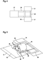
- Fig. 5 shows a transmission 22 with a gearbox 45; the transmission 22 is suspended via suspension elements 47 on the gearbox 45.
- the layouts of the machine support module 17 and the electric module 16 are shown; the Geretespant 45 does not extend over the entire transverse extent 32 of the machine frame module.
- the transmission can be pulled via a rail system 46 from the machine support module 17 in the electric module 16; in the electric module, the transmission can be positioned over the component carrier 39.
- Fig. 6 shows a perspective view of the wind turbine with a tower 15, a machine support module 17 and an electric module 16.
- the electric module 16 is half open and shown empty.
- the roof 38 of the electric module 16 consists of several segments; the middle segment is shifted against the outer segments and releases an opening.
- the generator 23 and the transformer 25 rest, shown schematically, on the component carrier 39.
- the component carrier 39 can be connected via four bolts 40 to the central frame 30; the central frame 30 has on each side two openings 37.
- the component carrier rests on a lifting platform 41, wherein the lifting platform 41 via ropes 42 with the central frame 30th of the electric module 16 is connected.
- the lifting platform 41 is part of the system for servicing the nacelle component according to the invention. With winches 43 of the lifting platform 41, the free length of the cables 42 can be changed, whereby a vertical method of the lifting platform 41 is effected. As a result, a transport of the component carrier 39 and the elements generator 23 and transformer 25 between the foot of the tower 15 and the electric module 16 is made possible.
- Fig. 7 shows a lifting platform 41 with winches 43, which carries a service crane 44.
- the component carrier 41 and the crane 44 are elements of the system for servicing a nacelle component according to the invention.
- the component carrier 41 loaded with the service crane 44 can be connected to the central frame 30 of the electric module 16 via the cables 42 of the winches 43.
- the in Fig. 7 shown component carrier 41 may instead of the in Fig. 6 shown component carrier are moved vertically relative to the nacelle component; the in Fig. 7 shown service crane 44 may instead of the in Fig. 6 shown elements generator 23 and transformer 25 are transported between the bottom of the tower 15 and the nacelle component.
- the service crane 44 When the service crane 44 is connected to the electric module 16, it can be used to move heavy components such as the transmission or generator within the nacelle.
- the service crane 44 can also be used to lift other components of the nacelle or tools needed for the maintenance of the wind turbine, for example from the base of the tower to the nacelle.
- the machine support module 17 and the electric module 16 can be brought into a preassembled state.
- the machine carrier module 17 is then equipped with the rotor shaft 20, the gear 22 and the turntable 12.
- the electric module 16 is connected to the generator 23, the inverter 24, the transformer 25 and the control cabinets 26 equipped.
- the generator 23, the inverter 24 and the transformer 25 are electrically connected to each other and connected to the control cabinets 26, that already in the factory a complete functional verification of the components of the electric module 16 can be performed.
- Both modules 16, 17 have a width of 4 m, a height of not more than 4 m and a length between 7 m and 10 m. Given these dimensions, a road-bound transport with manageable effort is possible.
- the machine support module 17 and the electric module 16 are connected to each other by screws and the input shaft 28 of the generator 23 is connected to the fast shaft of the transmission 22.
- the nacelle component is then in an assembled state. After attaching other elements, such as a housing, the finished nacelle 14 is raised and placed on top of the tower 15. Depending on the dimensions of the wind turbine and the availability of cranes, it may be more economical to lift the gondola separately in individual modules on the tower and connect there.
- the individual modules, machine carrier module 17 and electric module 16 can also be lifted piece by piece in elements on the tower and mounted there.
- An azimuth bearing is mounted between the nacelle 14 and the tower 15 so that the nacelle 14 can rotate relative to the tower 15.
- a medium voltage cable is fed from the transformer 25 via the machine support module 16 and the interior of the tower 15 to the tower base and connected there to a connection network.
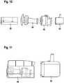
- Fig. 8 a first deployment condition is shown in which the wind turbine component can be brought to the ground.
- the machine carrier 60 is raised with the side walls of the housing to the upper end of the tower 15.
- the electric module 63 is raised with the electrical components.
- the rotor is added as a whole or in components.
- a second set-up condition is shown in which the wind turbine component can be brought to the ground.
- the first transport unit is formed by the machine carrier 60 with the side walls of the housing and the electric module 63.
- the second transport unit is formed by the driveline 61 with the roof 62 of the enclosure. Subsequently, the rotor is added as a whole or in components.
- the first transport unit is formed by the machine carrier 60 with the side walls of the housing.
- the second transport unit is formed by the majority driveline 64 without the transmission 65.
- the transmission 65 forms the third transport unit.
- the electric module 63 forms the fourth transport unit. Subsequently, the rotor is added as a whole or in components.
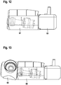
- FIG. 12 shows a fourth construction state in which the first transport unit 66 includes the machine frame 60, the driveline 61, and the enclosure.
- the electric module 63 forms the second transport unit. Subsequently, the rotor is added as a whole or in components.
- the first transport unit 67 comprises the entire nacelle with the machine carrier, the drive train, the housing and the electric module. Subsequently, the rotor is added as a whole or in components.
- the nacelle comprises the rotor hub 69.
- the rotor blades are successively connected to the rotor hub 69, wherein each of the rotor blades forms a further transport unit.
Landscapes
- Engineering & Computer Science (AREA)
- Life Sciences & Earth Sciences (AREA)
- Sustainable Development (AREA)
- Sustainable Energy (AREA)
- Chemical & Material Sciences (AREA)
- Combustion & Propulsion (AREA)
- Mechanical Engineering (AREA)
- General Engineering & Computer Science (AREA)
- Power Engineering (AREA)
- Wind Motors (AREA)
Abstract
Description
- Die Erfindung betrifft eine Gondelkomponente für eine Windenergieanlage. Die Erfindung betrifft außerdem ein Verfahren zum Montieren einer Gondelkomponente.
- Bei Windenergieanlagen ist üblicherweise eine Gondel drehbar auf einem Turm angeordnet. Die Gondel trägt einen Rotor, der über eine Rotorwelle an einem Generator angeschlossen ist. Der Rotor wird durch den Wind in Drehung versetzt und treibt den Generator an, sodass elektrische Energie erzeugt wird. Durch Drehen der Gondel relativ zu dem Turm kann der Rotor in Windrichtung ausgerichtet werden.
- Mit zunehmender Leistung werden die Komponenten der Windenergieanlage größer und schwerer, wodurch der Aufwand beim Transport und bei der Montage ansteigt. Es ist bekannt, eine Gondel aus mehreren Modulen zusammenzusetzen,
WO 2016/116112 A1 ,EP 2 573 387 A1 . Die einzelnen Module können mit überschaubarem Aufwand aus der Fertigungsstätte zu dem Ort transportiert werden, an dem die Windenergieanlage errichtet wird. Allerdings fällt beim Errichten der Windenergieanlage einiger Aufwand an, wenn die Gondel aus einer größeren Zahl von Modulen zusammengesetzt werden muss. - Der Erfindung liegt die Aufgabe zugrunde, eine Gondelkomponente und ein Verfahren zum Montieren einer Gondelkomponente vorzustellen, mit denen sowohl der Transportaufwand als auch der Aufwand beim Errichten der Windenergieanlage gering gehalten werden können. Ausgehend vom genannten Stand der Technik wird die Aufgabe gelöst mit den Merkmalen der unabhängigen Ansprüche. Vorteilhafte Ausführungsformen sind in den Unteransprüchen angegeben.
- Die erfindungsgemäße Gondelkomponente umfasst ein Maschinenträgermodul und ein Elektromodul. Das Maschinenträgermodul und das Elektromodul sind jeweils in Längsausdehnung größer als in Querausdehnung. Im zusammengesetzten Zustand der Gondelkomponente ist das Maschinenträgermodul mit seiner Längsausdehnung entlang einer senkrechten Ebene ausgerichtet, die sich durch die Rotorwellenachse erstreckt. Das Elektromodul schneidet im zusammengesetzten Zustand mit seiner Längsausdehnung die senkrechte Ebene, die sich durch die Rotorwellenachse erstreckt. Zusammengesetzter Zustand bezeichnet den Zustand, in dem das Elektromodul bestimmungsgemäß mit dem Maschinenträgermodul verbunden ist.
- Indem die beiden Module in der Gondelkomponente mit unterschiedlicher Ausrichtung angeordnet werden, kann der zur Verfügung stehende Raum effektiv ausgenutzt werden, wodurch die Gondel aus einer verminderten Zahl von Modulen zusammengesetzt werden kann. Trotzdem sind die Module noch so dimensioniert, dass sie gut transportiert werden können. Durch das quer angeordnete Elektromodul kann außerdem eine günstige Lastverteilung erreicht werden, weil die auf dem Elektromodul angeordneten Komponenten einen verringerten Abstand zu der Drehachse der Gondel haben. Dadurch kann das Lastmoment reduziert werden.
- Das Maschinenträgermodul und/oder das Elektromodul können bezogen auf die mit der Längsausdehnung und der Querausdehnung aufgespannte Ebene eine rechteckige Form oder eine an ein Rechteck angenäherte Form haben. Bei einem Rechteck bezeichnet die Längsausdehnung die längere der beiden Achsen und die Querausdehnung die kürzere der beiden Achsen. Haben das Maschinenträgermodul und/oder das Elektromodul eine von einem Rechteck abweichende Form, so beziehen sich die erfindungsgemäße Längsausdehnung und Querausdehnung auf das kleinste Rechteck, mit dem das betreffende Modul umgeben werden kann.
- Im zusammengesetzten Zustand der Gondelkomponente kann die Querausdehnung des Maschinenträgermoduls horizontal ausgerichtet sein. Die Längsausdehnung des Maschinenträgermoduls kann sich parallel zu der Rotorwellenachse erstrecken. Die Längsausdehnung des Elektromoduls kann sich in horizontaler Richtung erstrecken und unter einem rechten Winkel zu der Rotorwellenachse ausgerichtet sein. Die Querausdehnung des Elektromoduls kann sich parallel zu der Rotorwellenachse erstrecken. Die Querausdehnung des Maschinenträgermoduls und die Längsausdehnung des Elektromoduls sind vorzugsweise parallel zueinander. Die Querausdehnung des Elektromoduls kann in Verlängerung der Längsausdehnung des Maschinenträgermoduls angeordnet sein
- Das Maschinenträgermodul kann eine Aufnahme für eine Rotorwelle umfassen. Durch die Aufnahme kann die Richtung der Rotorwellenachse definiert sein. Die Aufnahme kann insbesondere so gestaltet sein, dass die Rotorwelle sich im montierten Zustand parallel zu der Längsausdehnung des Maschinenträgermoduls erstreckt. Die Aufnahme kann Lagerböcke aufweisen, an der eines oder mehrere Lager für die Rotorwelle angebracht werden können. Möglich ist auch, dass das Maschinenträgermodul in einen vormontierten Zustand gebracht wird, in dem eine Rotorwelle von dem Maschinenträgermodul getragen wird und über Lager drehbar relativ zu dem Maschinenträgermodul gelagert ist.
- Das Maschinenträgermodul kann eine Aufnahme für ein Getriebe umfassen. Die Aufnahme für das Getriebe kann separat von der Aufnahme für die Rotorwelle sein. Möglich ist auch, dass das Maschinenträgermodul eine gemeinsame Aufnahme umfasst, die die Rotorwelle und das Getriebe trägt. Das Maschinenträgermodul kann in einen vormontierten Zustand gebracht werden, in dem die Rotorwelle drehbar relativ zu dem Maschinenträgermodul gelagert ist und das Getriebe in einer festen Position relativ zu dem Maschinenträgermodul angebracht ist. Die Rotorwelle kann an die langsame Welle des Getriebes angeschlossen sein. Die schnelle Welle kann an einem gegenüberliegenden Ende des Getriebes angeordnet sein und sich parallel zu der Längsausdehnung des Maschinenträgermoduls erstrecken. An dem anderen Ende der Rotorwelle kann eine Rotornabe angebracht sein. Die Rotornabe kann eine Mehrzahl von Anschlüssen für Rotorblätter aufweisen, insbesondere drei Anschlüsse für Rotorblätter.
- Die erfindungsgemäße Gondelkomponente kann ein Getriebe umfassen. Das Getriebe kann über eine Getriebeaufnahme mit dem Maschinenträgermodul und/oder mit dem Elektromodul verbunden sein. Zwischen dem Getriebe und der Getriebeaufnahme kann eine Drehmomentstütze angeordnet sein, die einer Drehung des Getriebes relativ zu der Getriebeaufnahme entgegenwirkt. Die Drehmomentstütze kann einen Getriebespant umfassen, der starr mit der Getriebeaufnahme verbunden ist. Zwischen dem Getriebespant und dem Getriebekörper kann eine Mehrzahl von Aufhängungselementen angeordnet sein, insbesondere wenigstens drei Aufhängungselemente, vorzugsweise wenigstens fünf Aufhängungselemente, weiter vorzugsweise wenigstens zehn Aufhängungselemente. Die Aufhängungselemente können elastisch sein und insbesondere so ausgelegt sein, dass sie eine elastische Ausgleichsbewegung zwischen dem Getriebespant und dem Getriebekörper zulassen, wenn ein großes Drehmoment auf die langsame Getriebewelle wirkt. Es kann eine zu der langsamen Getriebewelle senkrechte Ebene geben, die die Aufhängungselemente der Drehmomentstütze schneidet. Eines oder mehrere oder alle der Aufhängungselemente können einen Lagerbolzen umfassen. Der Lagerbolzen kann sich parallel zur Rotorwelle erstrecken. Der Lagerbolzen kann mit dem Getriebespant oder mit dem Getriebekörper starr verbunden sein, während die Verbindung zwischen dem Lagerbolzen und dem jeweils anderen Element elastisch gestaltet ist. Beispielsweise kann um den Lagerbolzen herum ein elastisches Material angeordnet sein, das durch eine Bewegung des Getriebekörpers relativ zu dem Getriebespant komprimiert werden kann. Die Aufhängungselemente können kranzförmig um die langsame Welle des Getriebes herum angeordnet sein, mit anderen Worten kann die Drehmomentstütze eine Mehrzahl von Aufhängungselementen umfassen, die mit einem übereinstimmenden Abstand zu der langsamen Welle des Getriebes angeordnet sind. Die Aufhängungselemente können gleichverteilt über den Umfang der langsamen Getriebewelle angeordnet sein. Möglich ist auch, dass die Aufhängungselemente nicht gleichverteilt über den Umfang der langsamen Getriebewelle angeordnet sind. In einer Ausführungsform umfasst die Drehmomentstütze einen ersten Umfangsabschnitt, der mit Aufhängungselementen versehen ist, und einen zweiten Umfangsabschnitt, der frei von Aufhängungselementen ist. Der erste Umfangsabschnitt kann sich beispielsweise über einen Umfangswinkel zwischen 180° und 270° erstrecken. Der zweite Umfangsabschnitt kann sich beispielsweise über einen Umfangswinkel zwischen 90° und 180° erstrecken. Innerhalb des ersten Umfangsabschnitts können die Aufhängungselemente gleichmäßig über den Umfang verteilt sein. Ein Getriebe mit einer Drehmomentstütze, die eines oder mehrere der genannten Merkmale aufweist, hat eigenständigen erfinderischen Gehalt, auch wenn das Getriebe nicht im Zusammenhang einer erfindungsgemäßen Gondelkomponente verwendet wird. Durch eine solche Drehmomentstütze kann das Getriebe in Querrichtung schmaler gestaltet werden als bei einer konventionellen Drehmomentstütze, die zwei in Querrichtung vorspringende Arme umfasst. Dies kann von Vorteil sein, wenn ein Austausch des Getriebes erforderlich wird. Beispielsweise kann ein kompaktes Getriebe entlang der Längsachse des Maschinenträgermoduls in das Elektromodul gezogen werden und von dort zum Fuß des Turms abgeseilt werden.
- In einer Ausführungsform der erfindungsgemäßen Gondelkomponente kann ein Generator an die schnelle Welle des Getriebes angeflanscht sein, wobei der Generator sich im montierten Zustand im Maschinenträgermodul befinden kann; das Maschinenträgermodul kann eine eigene Aufnahme für den Generator, eine Aufnahme für die Einheit aus Generator und Getriebe oder eine gemeinsame Aufnahme für Generator, Getriebe und Rotorwelle umfassen. Das Maschinenträgermodul kann in einen vormontierten Zustand gebracht werden, in dem die Rotorwelle drehbar gegenüber dem Maschinenträgermodul gelagert ist und über das Getriebe mit dem in einer festen Position relativ zu dem Maschinenträgermodul angebrachten Generator verbunden ist.
- Das Maschinenträgermodul kann einen Drehkranz umfassen, über den das Maschinenträgermodul an einen Turm einer Windenergieanlage angeschlossen werden kann. Die Achse des Drehkranzes kann zusammenfallen mit einer Drehachse, um die das Maschinenträgermodul bzw. eine Gondel, in der das Maschinenträgermodul aufgenommen ist, relativ zu dem Turm gedreht werden können. Die Drehachse kann mit einer Mittelachse des Turms übereinstimmen. Der Drehkranz kann als Anschluss für ein Lager ausgebildet sein, sodass ein Lagerring an dem Drehkranz und der andere Lagerring an dem oberen Ende des Turms angeschlossen werden kann. Mit einer Rotation des Lagers kann das Maschinenträgermodul relativ zu dem Turm gedreht werden. Das Lager kann im vormontierten Zustand mit dem Maschinenträgermodul verbunden sein.
- Das Elektromodul kann in einer Ausführungsform der erfindungsgemäßen Gondelkomponente eine Aufnahme für einen Generator umfassen. Das Elektromodul kann in einen vormontierten Zustand gebracht werden, in dem der Generator mit dem Elektromodul verbunden ist. Im vormontierten Zustand sind das Elektromodul und das Maschinenträgermodul noch nicht miteinander verbunden. Der Generator kann so angeordnet sein, dass eine Eingangswelle des Generators sich parallel zu der Querausdehnung des Elektromoduls erstreckt. Die Eingangswelle des Generators kann außermittig in dem Elektromodul angeordnet sein, sodass bezogen auf die Längsausdehnung des Elektromoduls der Abstand zu dem einen Ende des Elektromoduls kleiner ist als der Abstand zu dem gegenüberliegenden Ende des Elektromoduls. Nimmt man einen Blickwinkel vom Generator in Richtung Eingangswelle ein, so kann der Abstand zu dem rechten Ende des Elektromoduls kleiner sein als der Abstand zu dem linken Ende des Elektromoduls. Das Elektromodul kann in einen vormontierten Zustand gebracht werden, in dem der Generator mit dem Elektromodul verbunden ist. Der Generator kann sich über wenigstens 40 %, vorzugsweise wenigstens 60 %, weiter vorzuweisen wenigstens 80 % der Querausdehnung des Elektromoduls erstrecken.
- Das Elektromodul kann mit einer Aufnahme für einen Umrichter ausgestattet sein. Das Elektromodul kann in einen vormontierten Zustand gebracht werden, in dem ein Umrichter mit dem Elektromodul verbunden ist. Es kann eine elektrische Verbindung zwischen dem Umrichter und dem Generator hergestellt werden, sodass ein Test des fehlerfreien Zusammenspiels zwischen dem Umrichter und dem Generator (Funktionstest) möglich ist. Der Umrichter kann bezogen auf die Längsausdehnung des Elektromoduls von dem Generator beabstandet sein. Bezogen auf die Querausdehnung des Elektromoduls kann der Umrichter mit dem Generator überlappen. Ist der Generator außermittig in dem Elektromodul angeordnet, so kann der Umrichter in dem größeren der beiden durch den Generator definierten Teilabschnitte des Elektromoduls angeordnet sein.
- Das Elektromodul kann eine Aufnahme für einen Transformator aufweisen. Das Elektromodul kann in einen vormontierten Zustand gebracht werden, in dem ein Transformator mit dem Elektromodul verbunden ist. Es kann eine elektrische Verbindung zwischen dem Transformator und dem Umrichter hergestellt werden, sodass ein Test des fehlerfreien Zusammenspiels zwischen dem Transformator, dem Umrichter und/oder dem Generator möglich ist.
- An den Transformator kann ein Mittelspannungskabel angeschlossen sein, das dazu ausgelegt ist, die mit dem Generator erzeugte elektrische Leistung an ein Anschlussnetz zu übertragen. Im zusammengesetzten Zustand der Gondelkomponente kann das Mittelspannungskabel über das Maschinenträgermodul in Richtung eines Turms der Windenergieanlage geführt sein.
- Der Transformator kann bezogen auf die Längsausdehnung des Elektromoduls von dem Generator beabstandet sein. Bezogen auf die Querausdehnung des Elektromoduls kann der Transformator mit dem Generator überlappen. Ist der Generator außermittig in dem Elektromodul angeordnet, so kann der Transformator in dem kleineren der beiden durch den Generator gebildeten Teilabschnitte des Elektromoduls angeordnet sein.
- Das Elektromodul kann eine Aufnahme für einen oder mehrere Schaltschränke umfassen. Das Elektromodul kann in einen vormontierten Zustand gebracht werden, in dem einer oder mehrere Schaltschränke mit dem Elektromodul verbunden sind. In den Schaltschränken kann eine Steuerung für den Generator, den Umrichter und/oder den Transformator angeordnet sein. Es kann eine elektrische Verbindung zwischen der Steuerung, dem Generator, dem Umrichter und/oder dem Transformator hergestellt werden, sodass ein Test des fehlerfreien Zusammenspiels der betreffenden Komponenten möglich ist.
- Der oder die Schaltschränke können bezogen auf die Längsausdehnung des Elektromoduls von dem Generator beabstandet sein. Bezogen auf die Querausdehnung des Elektromoduls können die Schaltschränke mit dem Generator überlappen. Ist der Generator außermittig in dem Elektromodul angeordnet, so können die Schaltschränke in dem größeren der beiden durch den Generator gebildeten Teilabschnitte des Elektromoduls angeordnet sein. Die Schaltschränke können bezogen auf die Querausdehnung des Elektromoduls von dem Umrichter beabstandet sein. Bezogen auf die Längsausdehnung des Elektromoduls können die Schaltschränke mit dem Umrichter überlappen.
- Das Elektromodul kann mit einem Kühlsystem ausgestattet sein. Das Kühlsystem kann dazu ausgelegt sein, den Generator, den Transformator und/oder den Umrichter zu kühlen. Möglich ist auch, dass das Kühlsystem dazu ausgelegt ist, das Getriebe zu kühlen. Im Betriebszustand der Gondel kann sich eine Leitung zwischen dem Elektromodul und dem Maschinenträgermodul erstrecken, über die ein Kühlmedium zwischen dem Kühlsystem und dem Getriebe ausgetauscht wird.
- Das Elektromodul kann einen Zentralrahmen umfassen, der sich nur über einen Teil der Längsausdehnung des Elektromoduls erstreckt. Auf einer Seite oder auf beiden Seiten des Zentralrahmens kann sich ein Seitenrahmen anschließen, sodass der Zentralrahmen und die Seitenrahmen sich in Summe über die Längsausdehnung des Elektromoduls erstrecken. Der Zentralrahmen kann massiv ausgebildet sein und schwerere Komponenten des Elektromoduls tragen. Zu den schweren Komponenten kann beispielsweise der Generator gehören. Die Seitenrahmen können weniger massiv ausgebildet sein als der Zentralrahmen und leichtere Komponenten des Elektromoduls tragen. Zu den leichteren Komponenten können der Umrichter, der Transformator und/oder Schaltschränke gehören.
- Das Elektromodul kann ein Rahmenteil umfassen, innerhalb dessen ein nach unten offener Durchbruch ausgebildet ist. Der Durchbruch kann so bemessen und angeordnet sein, dass Komponenten einer auf einem Turm einer Windenergieanlage angeordneten Gondel durch den Durchbruch hindurch nach unten abgelassen werden können, beispielsweise zum Zwecke der Wartung oder Reparatur. Dabei kann es sich beispielsweise um Komponenten handeln, die im Betrieb der Windenergieanlage mit dem Maschinenträgermodul und/oder dem Elektromodul verbunden sind. Das Rahmenteil kann den Durchbruch rundherum umschließen. Möglich ist auch ein Rahmenteil, das den Durchbruch nur teilweise umschließt. Das Rahmenteil kann einen ersten Hauptträger und einen zweiten Hauptträger umfassen, wobei die Hauptträger den Durchbruch zwischen sich einschließen. Die Hauptträger können sich in Querrichtung des Elektromoduls erstrecken. Bezogen auf die Längsrichtung des Elektromoduls kann der Durchbruch zwischen den Hauptträgern angeordnet sein. In einer Ausführungsform stimmt das Rahmenteil mit dem Zentralträger des Elektromoduls überein. Ein Elektromodul mit einem Rahmenteil mit einem oder mehreren dieser Merkmale hat eigenständigen erfinderischen Gehalt, auch ohne dass das Elektromodul weitere Merkmale der erfindungsgemäßen Gondelkomponente aufweist.
- Das Elektromodul kann einen Komponententräger umfassen. Der Komponententräger kann Aufnahmen für Elemente des Elektromoduls umfassen; insbesondere kann der Komponententräger Aufnahmen für den Generator und/oder den Transformator umfassen. Der Komponententräger kann mit dem Rahmenteil des Elektromoduls verbunden sein. Die Befestigung zwischen dem Komponententräger und dem Rahmenteil kann lösbar sein. Ein Elektromodul mit einem solchen Komponententräger hat eigenständigen erfinderischen Gehalt, auch ohne dass das Elektromodul weitere Merkmale der erfindungsgemäßen Gondelkomponente aufweist.
- Im verbundenen Zustand kann der Komponententräger unterhalb des Rahmenteils angeordnet sein. Mit dem Komponententräger verbundene Komponenten können in den Durchbruch des Rahmenteils hineinragen. Der Komponententräger kann größer sein als der Durchbruch, sodass mit dem Komponententräger verbundene Komponenten seitlich benachbart zu dem Durchbruch angeordnet sind, wenn der Komponententräger mit dem Rahmenteil verbunden ist. Eine Komponente des Elektromoduls, die durch den Komponententräger aufgenommen wird, kann auf dem Komponententräger ruhen und/oder an dem Komponententräger befestigt sein. Zusätzlich kann die Komponente an dem Rahmenteil, einem Seitenrahmen oder sonstigen Elementen des Elektromoduls befestigt sein.
- Das Elektromodul kann in einen vormontierten Zustand gebracht werden, in dem der Komponententräger mit dem Rahmenteil verbunden ist und in dem ein oder mehrere Komponenten des Elektromoduls mit dem Komponententräger verbunden sind. Alternativ kann der Komponententräger auch in einem beliebigen späteren Stadium der Montage mit dem Rahmenteil des Elektromoduls verbunden werden oder wieder von dem Rahmenteil des Elektromoduls getrennt werden. Der Komponententräger kann so beschaffen sein, dass er, bestückt mit den von dem Komponententräger aufgenommenen Elementen des Elektromoduls, mit einer Hebevorrichtung bewegt werden kann; der Komponententräger kann hierzu Anlenkeinrichtungen, beispielsweise in Form von Ösen, Umlenkrollen und/oder Winden umfassen. Alternativ oder zusätzlich kann der Komponententräger dazu ausgelegt sein, mit einer Hebeplattform angehoben zu werden; der Komponententräger kann hierzu beispielsweise eine flache Unterseite für ein stabiles Aufliegen auf der Hebeplattform aufweisen und/oder an den Kanten kompatibel mit Containerecken oder Twistlocks sein, wodurch eine feste Verbindung zu einer geeigneten Hebeplattform ermöglicht wird. Der erfindungsgemäße Komponententräger erleichtert das Manövrieren von Elementen des Elektromoduls zwischen der auf dem Turm installierten Gondel und dem Boden, wodurch ein Komponentenaustausch oder die Reparatur von Komponenten am Boden erleichtert werden.
- In Form einer eigenständigen Erfindung betrifft die Anmeldung außerdem ein System zum Ablassen einer Windenergieanlagenkomponente von der Gondel zum Boden. Das System umfasst eine Hebeplattform mit einem Hubweg, der sich zwischen der auf dem Turm angeordneten Gondel und dem Boden erstreckt. Die Hebeplattform kann ein Element der Gondel oder ein separates Teil sein. Während des Hubvorgangs kann die Hebeplattform an einem oder mehreren Seilen aufgehängt sein, die in geeigneter Weise eingeholt oder ausgelassen werden, beispielsweise durch Drehen einer oder mehrerer Winschen. In einer Ausführungsform ist der Antrieb zum Einholen oder Auslassen der Seile mit der Hebeplattform verbunden. Wenn die Hebeplattform am Boden steht, kann das Seil von der Gondel aus hereingeholt werden, während der Antrieb im Freilauf ist. Wenn ein Ende des Seils mit der Gondel verbunden ist, kann die Hebeplattform durch Betätigen des Antriebs angehoben werden. Wenn die Hebeplattform bis an die Gondel herangeführt ist, können eine oder mehrere Komponenten der Gondel auf die Hebeplattform gebracht werden und mit der Hebeplattform wieder abgelassen werden. Möglich ist auch, dass der Antrieb der Hebeplattform ein Element der Gondel ist.
- In einer Ausführungsform entspricht die Hebeplattform dem Komponententräger des Elektromoduls. Der Komponententräger kann von dem Rahmenteil des Elektromoduls gelöst werden und zusammen mit den daran befestigten Komponenten als Hebeplattform abgelassen werden.
- Wenn die Hebeplattform ein separates Teil ist, kann diese von unten an den Komponententräger des Elektromoduls herangeführt werden. Sobald der Komponententräger durch die Hebeplattform von unten abgestützt ist, kann der Komponententräger von dem Rahmenteil gelöst werden und mit der Hebeplattform nach unten gehoben werden. Um zu verhindern, dass der Komponententräger gegenüber der Hebeplattform verrutscht, kann ein Verbindungsmittel zwischen dem Komponententräger und der Hebeplattform vorgesehen sein, beispielsweise in Form von Containerecken/Twistlocks, wie sie von ISO-Containern bekannt sind
- Das System kann einen Servicekran umfassen. Der Servicekran kann dazu ausgelegt sein, auf einem Rahmen installiert zu werden; insbesondere kann der Servicekran dazu ausgelegt sein, auf dem Komponententräger oder der Hebeplattform installiert zu werden. Der Servicekran kann kompakte Ausmaße haben; vorzugsweise kann der Servicekran im Ganzen und in einsatzbereitem Zustand in einem ISO-Container transportiert werden. Der Servicekran kann dazu ausgelegt sein, größere Lasten anzuheben; eine größere Last kann beispielsweise das Getriebe oder der Generator sein. Der Servicekran kann genutzt werden, um das Getriebe und/oder den Generator ausgehend von einer Betriebsposition innerhalb der Gondel in eine Position zu bewegen, in der die Komponente aus der Gondel abgelassen werden kann.
- Das System kann eine Hilfshebevorrichtung umfassen, wobei die Hilfshebevorrichtung zum Auf- und Abseilen kleinerer Lasten zwischen der auf dem Turm installierten Gondelkomponente und dem Boden ausgelegt sein kann. Eine kleinere Last können beispielsweise die Seile der Winden der Hebeplattform sein. Die Hilfshebevorrichtung kann beispielsweise ein Bordkran oder eine Winde sein. Das Maschinenträgermodul oder vorzugsweise das Elektromodul kann eine Aufnahme für die Hilfshebevorrichtung umfassen. Das Maschinenträgermodul oder das Elektromodul kann in einen vormontierten Zustand gebracht werden, in dem die Hilfshebevorrichtung mit dem Maschinenträgermodul oder dem Elektromodul verbunden ist. Als Anwendungsbeispiel des Systems ist jeweils das Ablassen einer Komponente aus der Gondel der Windenergieanlage beschrieben. In entsprechender Weise kann das System genutzt werden, um eine Komponente vom Boden zu der Gondel anzuheben und dort zu installieren. Die Erfindung betrifft außerdem entsprechende Verfahren zum Ablassen einer Komponente aus der Gondel einer Windenergieanlage und zum Anheben einer Komponente zu der Gondel einer Windenergieanlage. Das Elektromodul und/oder das Maschinenträgermodul können Einhausungen umfassen, wobei die Einhausungen die Komponenten des Elektromoduls und/oder des Maschinenträgermoduls beispielsweise vor Umwelteinflüssen schützen. Die Einhausung des Elektromoduls kann selbsttragend sein. Dies kann insbesondere bedeuten, dass ein seitliches Einhausungsteil zwischen einem oberen Ende und einem unteren Ende erstreckt, ohne in der Fläche durch ein Rahmenskelett gestützt zu sein. Entlang der oberen, unteren und/oder seitlichen Enden des Einhausungsteils können sich Rahmenstreben des Elektromoduls erstrecken. Entlang seiner Kanten kann das Einhausungsteil mit den Rahmenstreben verbunden sein. Die selbsttragende Ausführung spart Platz und Gewicht. Ein Elektromodul mit einer solchen Einhausung hat eigenständigen erfinderischen Gehalt, auch wenn das Elektromodul nicht im Zusammenhang einer erfindungsgemäßen Gondelkomponente genutzt wird.
- Die Einhausung des Elektromoduls kann aus einem elektrisch leitfähigen Material und/oder aus einem Material mit guter Wärmeleitfähigkeit gefertigt sein. Insbesondere kann die Einhausung wenigstens abschnittsweise aus Blech gefertigt sein. Aufgrund der elektrischen Leitfähigkeit kann die Einhausung als faradayscher Käfig wirken, wodurch ein verbesserter Blitzschutz gegeben ist. Aufgrund einer guten Wärmeleitfähigkeit kann die Einhausung in das bestehende Kühlsystem integriert werden; die Wände des Elektromoduls können beispielsweise als Kühlelement genutzt werden. Die Wände des Elektromoduls können beispielsweise aus Trapezblech bestehen, wie es vom Aufbau eines ISO-Containers bekannt ist. Die Wände können eine hinreichende Stabilität aufweisen, so dass kleinere Elemente des Elektromoduls direkt an einer Wand aufgehängt werden können. Das Dach des Elektromoduls kann aus mehreren Segmenten bestehen, wobei einzelne Segmente solchermaßen verschiebbar gelagert sind, dass von oben ein Zugang ins Innere des Elektromoduls freigelegt werden kann; alternativ sind einzelne Segmente des Dachs oder das gesamte Dach abnehmbar ausgeführt. Das Elektromodul und/oder das Maschinenträgermodul können in einen vormontierten Zustand gebracht werden, in dem Teile der Einhausungen oder die gesamte Einhausung fest mit dem Elektromodul und/oder dem Maschinenträgermodul verbunden sind. Ein Elektromodul mit einer Einhausung, die eine oder mehrere dieser Merkmale aufweist, hat eigenständigen erfinderischen Gehalt, auch ohne dass das Elektromodul weitere Merkmale der erfindungsgemäßen Gondelkomponente aufweist.
- Im zusammengesetzten Zustand, in dem das Maschinenträgermodul und das Elektromodul miteinander verbunden sind, kann der Zentralrahmen des Elektromoduls sich in Verlängerung eines Rahmenelements des Maschinenträgermoduls erstrecken. Das Rahmenelement des Maschinenträgermoduls erstreckt sich vorzugsweise parallel zur Längsausdehnung des Maschinenträgermoduls.
- Das Maschinenträgermodul kann eine Verbindungseinrichtung zum Herstellen einer Verbindung mit dem Elektromodul umfassen. Die Verbindungseinrichtung kann beispielsweise Stehbolzen umfassen oder Bohrungen, durch die Bolzen hindurch geführt werden können. Die Verbindungseinrichtung kann an einer Querseite des Maschinenträgermoduls angeordnet sein, insbesondere an derjenigen Querseite, die von dem Rotor entfernt ist.
- Das Elektromodul kann eine Verbindungseinrichtung zum Herstellen einer Verbindung mit dem Maschinenträgermodul umfassen. Die Verbindungseinrichtung kann beispielsweise Bohrungen umfassen, die passend zu Bohrungen oder Stehbolzen des Maschinenträgermoduls angeordnet sind. Möglich sind auch Stehbolzen, die passend zu Bohrungen des Maschinenträgermoduls angeordnet sind. Die Verbindungseinrichtung kann an einer Längsseite des Elektromoduls angeordnet sein, insbesondere an derjenigen Längsseite, zu der die Eingangswelle des Getriebes weist. Beim Herstellen der Verbindung zwischen dem Maschinenträgermodul und dem Elektromodul kann die Eingangswelle des Generators an die schnelle Welle des Getriebes angeschlossen werden. Die Eingangswelle des Generators kann im zusammengesetzten Zustand koaxial zur schnellen Welle des Getriebes ausgerichtet sein.
- Die Verbindungseinrichtung zwischen dem Maschinenträgermodul und dem Elektromodul kann so gestaltet sein, dass das Maschinenträgermodul mittig an der Längsseite des Elektromoduls befestigt wird. Die Verbindungseinrichtung zwischen dem Maschinenträgermodul und dem Elektromodul ist vorzugsweise so stabil ausgebildet, dass das Maschinenträgermodul und das Elektromodul im zusammengesetzten Zustand als eine Einheit angehoben bzw. bewegt werden können. Das Maschinenträgermodul und/oder das Elektromodul können Anlenkeinrichtungen, beispielsweise in Form von Ösen umfassen, über die das Maschinenträgermodul und das Elektromodul als eine Einheit manövriert werden können.
- Das Maschinenträgermodul und/oder das Elektromodul können mit einem Schienensystem ausgestattet sein, das dazu ausgelegt ist, eine Komponente der Gondel, deren Verbindung zu dem Maschinenträgermodul bzw. dem Elektromodul in einem Wartungszustand gelöst ist, relativ zu dem Maschinenträgermodul und/oder dem Elektromodul zu bewegen. Das Schienensystem kann einen mit dem Maschinenträgermodul verbundenen Abschnitt und/oder einen mit dem Elektromodul verbundenen Abschnitt umfassen. Das Schienensystem kann genutzt werden, um eine Komponente, die im Betrieb der Windenergieanlage mit dem Maschinenträgermodul verbunden ist, in Richtung des Elektromoduls zu bewegen. Aus dem Elektromodul heraus kann die Komponente zum Zwecke der Wartung oder Reparatur abgelassen werden. Ein solches Verfahren kann insbesondere nützlich sein, um einen Generator und/oder ein Getriebe aus der Gondel der Windenergieanlage abzulassen. Das Getriebe und der Generator können separat voneinander mit dem Schienensystem bewegt werden. Möglich ist auch, dass das Getriebe und der Generator gemeinsam als Einheit mit dem Schienensystem bewegt werden. Eine Gondel einer Windenergieanlage, die mit einem Schienensystem mit einem oder mehreren dieser Merkmale ausgestattet ist, hat eigenständigen erfinderischen Gehalt, auch ohne dass die Gondel weitere Merkmale der Erfindung aufweist. Die Erfindung betrifft außerdem ein Wartungsverfahren, bei dem eine Komponente einer Windenergieanlage zunächst in im Wesentlichen horizontaler Richtung innerhalb der Gondel bewegt wird und dann aus der Gondel abgelassen wird. Die im Wesentlichen horizontale Bewegung kann unter Nutzung eines solchen Schienensystems stattfindet. Ein in dem Elektromodul vorgesehener Weg zum Ablassen einer Komponente der Gondel kann auf diese Weise auch für solche Komponenten genutzt werden, die im Betrieb der Windenergieanlage mit dem Maschinenträgermodul verbunden sind. Der Begriff Ablassen im Sinne der Erfindung umfasst sowohl einen Transportweg, bei dem die Komponente durch den Boden hindurch aus der Gondel entfernt wird, als auch einen Transportweg, bei dem die Komponente durch eine Seitenwand hindurch aus der Gondel entfernt wird, als auch einen Transportweg, bei dem die Komponente durch die Decke hindurch aus der Gondel entfernt.
Die Querausdehnung des Maschinenträgermoduls kann kleiner sein als die Längsausdehnung des Elektromoduls. Bezogen auf die Querausdehnung können das Maschinenträgermodul und das Elektromodul ähnlich dimensioniert sein. Insbesondere kann die Querausdehnung des Elektromoduls um weniger als 50 %, vorzugsweise weniger als 20 %, weiter vorzugsweise weniger als 10 % von der Querausdehnung des Maschinenträgermoduls abweichen. - Die Querausdehnung des Maschinenträgermoduls und/oder die Querausdehnung des Elektromoduls können beispielsweise zwischen 2 m und 6 m, vorzugsweise zwischen 3 m und 5 m, weiter vorzugsweise zwischen 3,5 m und 4,5 m liegen. Mit einer Querausdehnung in dieser Größenordnung ist noch mit vertretbarem Aufwand ein Straßentransport möglich. Die Längsausdehnung des Maschinenträgermoduls und/oder die Längsausdehnung des Elektromoduls können beispielsweise zwischen 120 % und 400 %, vorzugsweise zwischen 150 % und 300 % der Querausdehnung des betreffenden Moduls liegen. Die Höhe des Maschinenträgermoduls und/oder des Elektromoduls sind vorzugsweise nicht größer als 4 m. Die Längsausdehnung des Elektromoduls kann im zusammengesetzten Zustand mit der Längsausdehnung des Maschinenträgermoduls einen rechten Winkel einschließen.
- Die Erfindung betrifft auch eine Gondel, die eine solche Gondelkomponente umfasst. An die Rotorwelle der Gondelkomponente kann ein Rotor angeschlossen sein. Die Gondel kann mit einer das Maschinenträgermodul und das Elektromodul umgebenden Einhausung versehen sein.
- Die Erfindung betrifft außerdem eine Windenergieanlage, bei der eine solche Gondel drehbar auf einem Turm angeordnet ist. Ein Azimutlager kann zwischen dem Maschinenträgermodul der Gondel und dem Turm angeordnet sein. Das Azimutlager kann an den Drehkranz der Maschinenträgermoduls angeschlossen sein. Ein Mittelspannungskabel kann sich von dem Elektromodul über das Maschinenträgermodul und durch den Turm hindurch bis zum Turmfuß erstrecken. Über das Mittelspannungskabel kann die mit dem Generator erzeugte elektrische Leistung an ein Anschlussnetz übertragen werden. Die Windenergieanlage kann eine Leistung von mindestens 2 MW haben. Die Windenergieanlage kann für einen Onshore-Betrieb ausgelegt sein.
- Die Erfindung betrifft außerdem ein Verfahren zum Montieren einer Gondelkomponente einer Windenergieanlage. Bei dem Verfahren werden ein Maschinenträgermodul und ein Elektromodul zu einem Montageort transportiert. Bei dem Transport sind das Maschinenträgermodul und/oder das Elektromodul in Längsrichtung ausgerichtet, d. h. die Bewegungsrichtung beim Transport ist parallel zu der Längsausdehnung des Maschinenträgermoduls bzw. des Elektromoduls. Am Montageort werden zudem das Maschinenträgermodul und das Elektromodul miteinander verbunden, sodass eine Querseite des Maschinenträgermoduls an eine Längsseite des Elektromoduls anstößt. Das Verfahren kann mit weiteren Merkmalen fortgebildet werden, die im Zusammenhang der erfindungsgemäßen Gondelkomponente beschrieben sind. Die Gondelkomponente kann mit weiteren Merkmalen fortgebildet werden, die im Zusammenhang dieses Verfahrens beschrieben sind.
- Beim Transport können das Maschinenträgermodul und/oder das Elektromodul in einem vormontierten Zustand sein. Vor dem Herstellen der Verbindung mit dem Maschinenträgermodul kann das Elektromodul einem Funktionstest unterzogen werden, bei dem das fehlerfreie Zusammenspiel zwischen dem Generator, dem Umrichter, dem Transformator und/oder einer zu diesen Komponenten gehörigen Steuerung geprüft wird.
Die Erfindung betrifft außerdem ein Errichtungssystem für eine Windenergieanlage, bei dem eine Mehrzahl von Windenergieanlagenkomponenten an einem oberen Ende eines Turms befestigt wird. Das Errichtungssystem umfasst einen ersten Errichtungszustand, in dem eine erste Windenergieanlagenkomponente und eine zweite Windenergieanlagenkomponente zu einer ersten Transporteinheit verbunden sind sowie eine dritte Windenergieanlagenkomponente Element einer zweiten Transporteinheit ist. In einem zweiten Errichtungszustand sind die erste Windenergieanlagenkomponente und die dritte Windenergieanlagenkomponente zu einer dritten Transporteinheit verbunden, wobei die zweite Windenergieanlagenkomponente entweder ebenfalls Element der dritten Transporteinheit ist oder Element einer vierten Transporteinheit ist. Am Boden wird entweder der erste Errichtungszustand oder der zweite Errichtungszustand hergestellt. Abhängig von der Wahl des Errichtungszustands erfolgt das Errichten der Windenergieanlage entweder durch Anheben der ersten Transporteinheit und der zweiten Transporteinheit zum oberen Ende des Turms oder durch Anheben der dritten Transporteinheit und der vierten Transporteinheit zum oberen Ende des Turms. - Ein Errichtungszustand kann mehr als zwei Transporteinheiten umfassen. Eine Transporteinheit kann mehr als zwei Windenergieanlagenkomponenten umfassen.
- In einem beispielhaften ersten Errichtungszustand besteht die erste Transporteinheit aus dem Maschinenträger. Die zweite Transporteinheit wird durch den Triebstrang (Rotorwelle plus Getriebe) gebildet. Eine dritte Transporteinheit wird durch das Elektromodul mit dem Generator, dem Umrichter und/oder weiteren elektrischen Komponenten gebildet. Eine vierte Transporteinheit kann der Rotor (Rotor plus Rotornabe) bilden. Alternativ können die Rotornabe und die Rotorblätter jeweils einzelne Transporteinheiten bilden. Diese beiden Möglichkeiten der Rotormontage geltend entsprechend für die nachfolgenden Errichtungszustände.
- In einem beispielhaften zweiten Errichtungszustand bildet die Gondel, bestehend aus dem Maschinenträger, dem Elektromodul (mit Generator, Umrichter und/oder weiteren elektrischen Komponenten) eine erste Transporteinheit. Der Triebstrang bildet eine zweite Transporteinheit. Weitere Transporteinheiten können den Rotor entweder in seiner Gesamtheit oder in einzelnen Komponenten umfassen.
- In einem beispielhaften dritten Errichtungszustand besteht die erste Transporteinheit aus dem Maschinenträger. Die zweite Transporteinheit besteht aus dem Triebstrang ohne Getriebe. Die dritte Transporteinheit besteht aus dem Getriebe. Die vierte Transporteinheit besteht aus dem Elektromodul (mit Generator, Umrichter und/oder weiteren elektrischen Komponenten). Weitere Transporteinheiten können den Rotor entweder in seiner Gesamtheit oder in einzelnen Komponenten umfassen.
- In einem beispielhaften vierten Errichtungszustand besteht die erste Transporteinheit aus dem Maschinenträger, inklusive Triebstrang und Einhausung. Die zweite Transporteinheit besteht aus dem Elektromodul (mit Generator, Umrichter und/oder weiteren elektrischen Komponenten). Weitere Transporteinheiten können den Rotor entweder in seiner Gesamtheit oder in einzelnen Komponenten umfassen.
In einem beispielhaften fünften Errichtungszustand besteht die erste Transporteinheit aus der Gondel inklusive Maschinenträger, Elektromodul (mit Generator, Umrichter und/oder weiteren elektrischen Komponenten), Einhausung. Weitere Transporteinheiten können den Rotor entweder in seiner Gesamtheit oder in einzelnen Komponenten umfassen. - In einem beispielhaften sechsten Errichtungszustand besteht die erste Transporteinheit aus der Gondel inklusive Maschinenträger, Elektromodul (mit Generator, Umrichter und/oder weiteren elektrischen Komponenten), Einhausung und Rotornabe. Weitere Transporteinheiten können einzelne Komponenten des Rotors umfassen.
- Die Reihenfolge, mit der die Transporteinheiten zur Spitze des Turms transportiert werden, kann der Reihenfolge entsprechen, in der die Transporteinheiten im Rahmen der vorgenannten Errichtungszustände aufgezählt sind. Möglich ist auch eine davon abweichende Reihenfolge beim Anheben der Transporteinheiten. Die Erfindung umfasst Variationen innerhalb der genannten Transporteinheiten. Beispielsweise ist es jeweils möglich, Elemente der Einhausung wahlweise einer ersten Transporteinheit oder einer zweiten Transporteinheit hinzuzufügen.
- Jede Transporteinheit kann einen oder mehrere Anlenkpunkte aufweisen. Die Anlenkpunkte können so angeordnet sein, dass sie den Schwerpunkt der Transporteinheit zwischen sich anschließen, sodass ein stabiles Anheben der Transporteinheit möglich ist.
- Je nach Gegebenheiten am Ort der Errichtung der Windenergieanlage sowie nach Verfügbarkeit von Arbeitsmitteln wie Kränen usw. können die Windenergieanlagenkomponenten am Boden in einen der Errichtungszustände gebracht werden. Mit dem erfindungsgemäßen Errichtungssystem wird also eine Mehrzahl von Möglichkeiten zur Verfügung gestellt, wie eine einzelne Windenergieanlage errichtet werden kann.
- Die Erfindung betrifft außerdem ein Verfahren zum Anbringen einer Mehrzahl von Windenergieanlagenkomponenten an einem oberen Ende eines Turms eine Windenergieanlage. In einem ersten Schritt wird ein erster Errichtungszustand aus einer Mehrzahl von zur Verfügung stehenden Errichtungszuständen ausgewählt. Die Windenergieanlagenkomponenten werden am Boden in den ersten Errichtungszustand gebracht. Eine erste Transporteinheit und eine zweite Transporteinheit werden zum oberen Ende des Turms angehoben, wobei jede Transporteinheit eine oder mehrere Windenergieanlagenkomponenten umfasst. Das Verfahren kann mit weiteren Merkmalen fortgebildet werden, die im Zusammenhang des erfindungsgemäßen Errichtungszustands beschrieben sind. Das Errichtungssystem kann mit weiteren Merkmalen fortgebildet werden, die im Zusammenhang dieses Verfahrens beschrieben sind.
- Die Erfindung wird nachfolgend unter Bezugnahme auf die beigefügten Zeichnungen anhand vorteilhafter Ausführungsformen beispielhaft beschrieben. Es zeigen:
- Fig. 1:
- eine schematische Darstellung einer erfindungsgemäßen Windenergieanlage;
- Fig. 2:
- eine perspektivische Darstellung einer erfindungsgemäßen Gondelkomponente im zusammengesetzten Zustand;
- Fig. 3:
- eine schematische Ansicht von oben auf eine erfindungsgemäße Gondelkomponente im zusammengesetzten Zustand;
- Fig. 4:
- eine schematische Ansicht von oben auf eine erfindungsgemäße Gondelkomponente im nicht zusammengesetzten Zustand;
- Fig. 5:
- eine perspektivische Darstellung eines Getriebes, eines Schienensystems und eines Komponententrägers auf dem Grundriss einer erfindungsgemäßen Gondelkomponente;
- Fig. 6:
- eine perspektivische Darstellung einer teilmontierten Gondelkomponente auf dem Turm einer Windenergieanlage sowie Elemente des Systems zur Wartung der Gondelkomponente;
- Fig. 7:
- eine perspektivische Darstellung von Elementen des Systems zur Wartung einer erfindungsgemäßen Gondelkomponente;
- Fig. 8 bis 13:
- verschiedene Errichtungszustände des erfindungsgemäßen Errichtungssystems;
- Fig. 14:
- eine perspektivische Darstellung einer erfindungsgemäßen Gondelkomponente.
- Bei einer in
Fig. 1 gezeigten erfindungsgemäßen Windenergieanlage ist eine Gondel 14 drehbar auf einem Turm 15 gelagert. Ein Rotor 16 wird durch den Wind in Drehung versetzt und treibt über ein Getriebe 22 einen Generator 23 an. Der Generator 23 erzeugt elektrischen Strom, der über einen Umrichter 24 und einen Transformator 25 in ein Anschlussnetz eingespeist wird. - Im Inneren der Gondel 14 ist eine in
Fig. 2 gezeigte Gondelkomponente angeordnet, die ein Elektromodul 16 und ein Maschinenträgermodul 17 umfasst. Das Maschinenträgermodul 17 umfasst Lagerböcke 18, 19, über die eine Rotorwelle 20 drehbar gelagert ist. An das vordere Ende der Rotorwelle 20 ist eine Rotornabe 21 angeschlossen. Das hintere Ende der Rotorwelle 20 ist mit der langsamen Welle eines Getriebes 22 verbunden. Das Maschinenträgermodul 17 umfasst einen Drehkranz 12, über den die Gondel 14 drehbar relativ zu dem Turm 15 gelagert ist. - Das Elektromodul 16 trägt einen Generator 23, einen Umrichter 24, einen Transformator 25 sowie Schaltschränke 26. Eine Eingangswelle 28 des Generators 23 ist mit der schnellen Welle des Getriebes 22 verbunden. Wenn die Rotorwelle 20 sich dreht, wird mit dem Generator 23 elektrische Energie erzeugt. Die elektrische Energie wird über den Umrichter 24 und den Transformator 25 auf eine Mittelspannung gebracht und in ein nicht dargestelltes Mittelspannungskabel eingespeist. Das Zusammenwirken zwischen dem Generator 23, dem Umrichter 24 und dem Transformator 25 wird durch eine Steuerung bestimmt, die in den Schaltschränken 26 untergebracht ist.
- Das Elektromodul 16 und das Maschinenträgermodul 17 sind durch Schrauben miteinander verbunden. Die Verbindung ist so stabil, dass die Gondelkomponente als eine Einheit angehoben werden kann.
- Gemäß der schematischen Darstellung in
Fig. 3 haben das Maschinenträgermodul 17 und das Elektromodul 16 in einem horizontalen Schnitt betrachtet jeweils eine rechteckige Form. Die Längsausdehnung 33 des Maschinenträgermoduls 17 erstreckt sich parallel zu der Rotorwelle 20, die Querausdehnung 32 des Maschinenträgermoduls 17 erstreckt sich unter einem rechten Winkel zu der Rotorwelle 20. Die Querausdehnung 34 des Elektromoduls 16 ist parallel zu der Rotorwelle 20 ausgerichtet, die Längsausdehnung 35 des Elektromoduls 16 schneidet die Rotorwelle 20 unter einem rechten Winkel. - Der Generator 23 ist leicht außermittig in dem Elektromodul 16 angeordnet. Nimmt man einen Blickwinkel von dem Generator 23 in Richtung der Eingangswelle 28 an, so ist der Generator 23 gegenüber der Mitte leicht nach rechts verschoben. Ebenfalls in der rechten Hälfte ist der Transformator 25 angeordnet. In der linken Hälfte des Elektromoduls 16 sind der Umrichter 24 und die Schaltschränke 26 angeordnet.
- Aus der Darstellung in
Fig. 3 geht hervor, dass die Komponenten des Elektromoduls 16 alle in einem geringen Abstand zu der Drehachse der Gondel 14 angeordnet sind. Dies ergibt eine günstige Lastverteilung, bei der das Azimut-Lager verminderten Belastungen ausgesetzt ist. - Gemäß
Fig. 4 umfasst das Maschinenträgermodul 17 an seinem hinteren Ende ein Rahmenelement 29, das sich in Längsrichtung erstreckt. Das Elektromodul 16 umfasst einen Zentralrahmen 30, der in Verlängerung des Rahmenelements 29 angeordnet ist, wenn das Elektromodul 16 und das Maschinenträgermodul 17 im verbundenen Zustand sind. Der Zentralrahmen 30 trägt die schweren Komponenten des Elektromoduls 16, insbesondere den Generator 23. An den Zentralrahmen 30 schließen zwei Seitenrahmen 31 an, die die leichteren Komponenten des Elektromoduls 16 tragen, nämlich den Umrichter 24, den Transformator 25 und die Schaltschränke 26. Sowohl der Zentralrahmen 30 als auch die Seitenrahmen 31 erstrecken sich über die gesamte Querausdehnung des Elektromoduls 16. In Summe erstrecken der Zentralrahmen 30 und die beiden Seitenrahmen 31 sich über die gesamte Längsausdehnung des Elektromoduls 16. - Bei der alternativen Ausführungsform gemäß
Fig. 14 ist ein Komponententräger 39 vorgesehen, der den Generator 23 und den Umrichter 25 trägt. Wenn die Windenergieanlage in Betrieb ist, ist der Komponententräger 39 mit dem Zentralrahmen 30 des Elektromoduls 16 verschraubt. Zum Zwecke der Wartung oder Reparatur kann der Komponententräger 39 von dem Zentralrahmen 30 gelöst werden und über Seile 50 bis zum Boden herabgelassen werden. Die Seile 50 sind über eine nicht dargestellte Windisch angetrieben. - Über den Umfang des Elektromoduls 16 erstrecken sich horizontaler Rahmenstreben 51, die durch senkrechte Rahmenstreben 52 miteinander verbunden sind. Die zwischen den Rahmen streben 51, 52 eingeschlossenen Wandflächen sind durch Trapezbleche 53 ausgefüllt, die selbsttragend sind und in der Fläche nicht durch ein weiteres Rahmenskelett abgestützt sind.
-
Fig. 5 zeigt ein Getriebe 22 mit einem Getriebespant 45; das Getriebe 22 ist über Aufhängungselemente 47 an dem Getriebespant 45 aufgehängt. Zusätzlich sind die Grundrisse des Maschinenträgermoduls 17 und des Elektromoduls 16 gezeigt; der Getriebespant 45 erstreckt sich nicht über die gesamte Querausdehnung 32 des Maschinenträgermoduls. Das Getriebe kann über ein Schienensystem 46 aus dem Maschinenträgermodul 17 in das Elektromodul 16 gezogen werden; in dem Elektromodul kann das Getriebe über dem Komponententräger 39 positioniert werden. -
Fig. 6 zeigt eine perspektivische Ansicht auf die Windenergieanlage mit einem Turm 15, einem Maschinenträgermodul 17 und einem Elektromodul 16. Das Elektromodul 16 ist halb geöffnet und leer dargestellt. Das Dach 38 des Elektromoduls 16 besteht aus mehreren Segmenten; das mittlere Segment ist gegen die äußeren Segmente verschoben und gibt eine Öffnung frei. Der Generator 23 und der Transformator 25 ruhen, schematisch dargestellt, auf dem Komponententräger 39. Der Komponententräger 39 kann über vier Bolzen 40 mit dem Zentralrahmen 30 verbunden werden; der Zentralrahmen 30 weist dazu auf jeder Seite zwei Öffnungen 37 auf. - Der Komponententräger ruht auf einer Hebeplattform 41, wobei die Hebeplattform 41 über Seile 42 mit dem Zentralrahmen 30 des Elektromoduls 16 verbunden ist. Die Hebeplattform 41 ist Teil des Systems zur Wartung der erfindungsgemäßen Gondelkomponente. Mit Winden 43 der Hebeplattform 41 kann die freie Länge der Seile 42 verändert werden, wodurch ein vertikales Verfahren der Hebeplattform 41 bewirkt wird. Hierdurch wird ein Transport des Komponententrägers 39 sowie der Elemente Generator 23 und Transformator 25 zwischen dem Fuß des Turms 15 und dem Elektromodul 16 ermöglicht.
-
Fig. 7 zeigt eine Hebeplattform 41 mit Winden 43, die einen Servicekran 44 trägt. Der Komponententräger 41 und der Kran 44 sind Elemente des Systems zur Wartung einer erfindungsgemäßen Gondelkomponente. Der mit dem Servicekran 44 beladene Komponententräger 41 kann über die Seile 42 der Winden 43 mit dem Zentralrahmen 30 des Elektromoduls 16 verbunden werden. Der inFig. 7 gezeigte Komponententräger 41 kann an Stelle des inFig. 6 gezeigten Komponententrägers vertikal gegenüber der Gondelkomponente verfahren werden; der inFig. 7 gezeigte Servicekran 44 kann an Stelle der inFig. 6 gezeigten Elemente Generator 23 und Transformator 25 zwischen dem Fuß des Turms 15 und der Gondelkomponente transportiert werden. Wenn der Servicekran 44 mit dem Elektromodul 16 verbunden ist, kann er genutzt werden, um schwere Komponenten wie das Getriebe oder den Generator innerhalb der Gondel zu bewegen. Der Servicekran 44 kann jedoch auch genutzt werden, um andere Komponenten der Gondel oder Werkzeuge, die für die Wartung der Windenregieanlage benötigt werden, beispielsweise vom Fuß des Turmes zur Gondel zu heben. - Bei der Montage einer erfindungsgemäßen Windenergieanlage kann wie folgt vorgegangen werden. An einer Fertigungsstätte können das Maschinenträgermodul 17 und das Elektromodul 16 in einen vormontierten Zustand gebracht werden. Das Maschinenträgermodul 17 ist dann mit der Rotorwelle 20, dem Getriebe 22 und dem Drehkranz 12 bestückt. Das Elektromodul 16 ist mit dem Generator 23, dem Umrichter 24, dem Transformator 25 und den Schaltschränken 26 bestückt. Der Generator 23, der Umrichter 24 und der Transformator 25 sind elektrisch miteinander verbunden und so an die Steuerschränke 26 angeschlossen, dass bereits in der Fertigungsstätte eine vollständige Funktionsüberprüfung der Komponenten des Elektromoduls 16 durchgeführt werden kann.
- Der Transport von der Fertigungsstätte zum Ort der Montage kann auf der Straße erfolgen. Beide Module 16, 17 haben eine Breite von 4 m, eine Höhe von nicht mehr als 4 m sowie eine Länge zwischen 7 m und 10 m. Angesichts dieser Dimensionen ist ein straßengebundener Transport mit überschaubarem Aufwand möglich.
- Am Ort der Montage werden das Maschinenträgermodul 17 und das Elektromodul 16 durch Schrauben miteinander verbunden und die Eingangswelle 28 des Generators 23 an die schnelle Welle des Getriebes 22 angeschlossen. Die Gondelkomponente ist dann in einen zusammengesetzten Zustand. Nach Anbringen von weiteren Elementen, wie beispielsweise einer Einhausung, wird die fertige Gondel 14 angehoben und auf das obere Ende des Turms 15 aufgesetzt. Je nach Abmessung der Windenergieanlage und der Verfügbarkeit von Kränen kann es wirtschaftlicher sein, die Gondel getrennt in einzelnen Modulen auf den Turm zu heben und dort zu verbinden. Die einzelnen Module, Maschinenträgermodul 17 und Elektromodul 16, können auch stückweise in Elementen auf den Turm gehoben werden und dort montiert werden. Zwischen der Gondel 14 und dem Turm 15 wird ein Azimutlager montiert, sodass die Gondel 14 sich relativ zu dem Turm 15 drehen kann. Ein Mittelspannungskabel wird von dem Transformator 25 über das Maschinenträgermodul 16 und das Innere des Turms 15 zum Turmfuß geführt und dort an ein Anschlussnetz angeschlossen.
- Gemäß den
Fig. 8 bis 13 gibt es verschiedene Möglichkeiten, wie beim Errichten der Windenergieanlage vorgegangen werden kann. InFig. 8 ist ein erster Errichtungszustand gezeigt, in den die Windenergieanlagenkomponente am Boden gebracht werden können. Als erste Transporteinheit wird der Maschinenträger 60 mit den Seitenwänden der Einhausung zum oberen Ende des Turms 15 angehoben. Als zweite Transporteinheit wird der Triebstrang 61 mit dem Dach 62 der Einhausung angehoben. Als dritte Transporteinheit wird das Elektromodul 63 mit den elektrischen Komponenten angehoben. Anschließend wird der Rotor als Ganzes oder in Komponenten hinzugefügt. - In
Fig. 9 ist ein zweiter Errichtungszustand gezeigt, in den die Windenergieanlagenkomponente am Boden gebracht werden können. Die erste Transporteinheit wird durch den Maschinenträger 60 mit den Seitenwänden der Einhausung und das Elektromodul 63 gebildet. Die zweite Transporteinheit wird durch den Triebstrang 61 mit dem Dach 62 der Einhausung gebildet. Anschließend wird der Rotor als Ganzes oder in Komponenten hinzugefügt. - Bei dem dritten Errichtungszustand in
Fig. 10 wird die erste Transporteinheit durch den Maschinenträger 60 mit den Seitenwänden der Einhausung gebildet. Die zweite Transporteinheit wird durch den Großteil-Triebstrang 64 ohne dass Getriebe 65 gebildet. Das Getriebe 65 bildet die dritte Transporteinheit. Das Elektromodul 63 bildet die vierte Transporteinheit. Anschließend wird der Rotor als Ganzes oder in Komponenten hinzugefügt. - Die
Fig. 11 zeigt einen vierten Errichtungszustand, bei dem die erste Transporteinheit 66 den Maschinenträger 60, den Triebstrang 61 und die Einhausung umfasst. Das Elektromodul 63 bildet die zweite Transporteinheit. Anschließend wird der Rotor als Ganzes oder in Komponenten hinzugefügt. - Bei dem fünften Errichtungszustand gemäß
Fig. 12 umfasst die erste Transporteinheit 67 die gesamte Gondel mit dem Maschinenträger, dem Triebstrang, der Einhausung und dem Elektromodul. Anschließend wird der Rotor als Ganzes oder in Komponenten hinzugefügt. - Bei dem sechsten Errichtungszustand gemäß
Fig. 13 umfasst die Gondel zusätzlich dazu die Rotornabe 69. An die Rotornabe 69 werden nacheinander die Rotorblätter angeschlossen, wobei jedes der Rotorblätter eine weitere Transporteinheit bildet.
Claims (15)
- Gondelkomponente für eine Gondel (14) einer Windenergieanlage, umfassend ein Maschinenträgermodul (17) und ein Elektromodul (16), wobei das Maschinenträgermodul (17) und das Elektromodul (16) jeweils in Längsausdehnung (33, 35) größer sind als in Querausdehnung (32, 34), wobei in einem zusammengesetzten Zustand der Gondelkomponente das Maschinenträgermodul (17) mit seiner Längsausdehnung (33) entlang einer sich durch die Achse einer Rotorwelle (20) erstreckenden senkrechten Ebene ausgerichtet ist und wobei das Elektromodul (16) mit seiner Längsausdehnung (35) die sich durch die Achse der Rotorwelle (20) erstreckende senkrechte Ebene schneidet.
- Gondelkomponente nach Anspruch 1, dadurch gekennzeichnet, dass das Maschinenträgermodul (17) eine Aufnahme (18, 19) für eine Rotorwelle (20) , eine Aufnahme für ein Getriebe (22) umfasst und/oder eine Aufnahme für einen Generator (23) umfasst.
- Gondelkomponente nach 1 oder 2, dadurch gekennzeichnet, dass das Maschinenträgermodul (17) einen Drehkranz (12) umfasst, der dazu ausgelegt ist, eine drehbare Verbindung zwischen dem Maschinenträgermodul (17) und einem Turm (15) einer Windenergieanlage zu bilden.
- Gondelkomponente nach einem der Ansprüche 1 bis 3, dadurch gekennzeichnet, dass das Elektromodul (16) eine Aufnahme für einen Generator (23) umfasst.
- Gondelkomponente nach Anspruch 4, dadurch gekennzeichnet, dass ein Generator (23) mit der Generatoraufnahme verbunden ist und dass eine Eingangswelle (28) des Generators (23) außermittig in dem Elektromodul (16) angeordnet ist.
- Gondelkomponente nach einem der Ansprüche 1 bis 5, dadurch gekennzeichnet, dass das Elektromodul (16) eine Aufnahme für einen Umrichter (24) umfasst.
- Gondelkomponente nach einem der Ansprüche 1 bis 6, dadurch gekennzeichnet, dass das Elektromodul (16) eine Aufnahme für einen Transformator (25) umfasst.
- Gondelkomponente nach einem der Ansprüche 1 bis 7, dadurch gekennzeichnet, dass ein Mittelspannungskabel an den Transformator (25) angeschlossen ist, das im zusammengesetzten Zustand der Gondelkomponente über das Maschinenträgermodul (17) in Richtung eines Turms (15) einer Windenergieanlage geführt ist.
- Gondelkomponente nach einem der Ansprüche 1 bis 8, dadurch gekennzeichnet, dass das Elektromodul ein Kühlsystem umfasst, das dazu ausgelegt ist, einen Generator (23), einen Umrichter (24), einen Transformator (25) und/oder ein Getriebe (23) zu kühlen.
- Gondelkomponente nach einem der Ansprüche 1 bis 9, dadurch gekennzeichnet, dass das Elektromodul (16) einen Zentralrahmen (30) umfasst, der sich nur über einen Teil der Längsausdehnung (35) des Elektromoduls (16) erstreckt und dass an den Zentralrahmen (30) zwei Seitenrahmen (31) anschließen.
- Gondelkomponente nach einem der Ansprüche 1 bis 10, dadurch gekennzeichnet, dass das Elektromodul (16) einen Komponententräger (39) umfasst, wobei der Komponententräger (39) abnehmbar an einem Zentralrahmen (30) des Elektromoduls (16) befestigt ist und wobei der Komponententräger (39) Elemente (22,23,24,25,26) des Elektromoduls (16) trägt.
- Gondelkomponente nach einem der Ansprüche 1 bis 11, dadurch gekennzeichnet, dass in einem vormontierten Zustand des Elektromoduls (16) ein Generator (23), ein Umrichter (24), ein Transformator (25) und/oder eine Steuerung (26) auf dem Elektromodul (16) installiert sind und so miteinander verbunden sind, dass ein Funktionstest der Komponenten möglich wird.
- Gondelkomponente nach einem der Ansprüche 1 bis 12, dadurch gekennzeichnet, dass die Querausdehnung (34) des Elektromoduls (16) um weniger als 50 %, vorzugsweise weniger als 20 %, weiter vorzugsweise weniger als 10 % von der Querausdehnung (32) des Maschinenträgermoduls (17) abweicht.
- Gondelkomponente nach einem der Ansprüche 1 bis 13, dadurch gekennzeichnet, dass die Querausdehnung (32) des Maschinenträgermoduls (17) und/oder die Querausdehnung (34) des Elektromoduls (16) zwischen 2 m und 6 m, vorzugsweise zwischen 3 m und 5 m, weiter vorzugsweise zwischen 3,5 m und 4,5 m liegen.
- Verfahren zum Montieren einer Gondelkomponente einer Windenergieanlage, bei dem ein Maschinenträgermodul (17) und ein Elektromodul (16) zu einem Montageort transportiert, wobei das Maschinenträgermodul (17) und/oder das Elektromodul (16) während des Transports in Längsrichtung (33, 35) ausgerichtet sind, und bei dem das Maschinenträgermodul (17) und das Elektromodul (16) am Montageort miteinander verbunden werden, sodass eine Querseite des Maschinenträgermoduls (17) an eine Längsseite des Elektromoduls (16) anstößt.
Applications Claiming Priority (1)
| Application Number | Priority Date | Filing Date | Title |
|---|---|---|---|
| DE102017004800.2A DE102017004800A1 (de) | 2017-05-18 | 2017-05-18 | Gondelkomponente für eine Windenergieanlage und Verfahren zum Montieren einer Gondelkomponente |
Publications (2)
| Publication Number | Publication Date |
|---|---|
| EP3406898A1 true EP3406898A1 (de) | 2018-11-28 |
| EP3406898B1 EP3406898B1 (de) | 2021-11-24 |
Family
ID=62196428
Family Applications (1)
| Application Number | Title | Priority Date | Filing Date |
|---|---|---|---|
| EP18172806.4A Active EP3406898B1 (de) | 2017-05-18 | 2018-05-17 | Gondelkomponente für eine windenergieanlage und verfahren zum montieren einer gondelkomponente |
Country Status (4)
| Country | Link |
|---|---|
| US (1) | US10781798B2 (de) |
| EP (1) | EP3406898B1 (de) |
| CN (1) | CN108953063B (de) |
| DE (1) | DE102017004800A1 (de) |
Cited By (4)
| Publication number | Priority date | Publication date | Assignee | Title |
|---|---|---|---|---|
| EP3786448A1 (de) * | 2019-08-29 | 2021-03-03 | General Electric Company | Verfahren zur montage einer gondel einer windturbine und montagesatz von teilen einer windturbine |
| US11300105B2 (en) | 2017-08-29 | 2022-04-12 | Vestas Wind Systems A/S | Wind turbine with a movable container housing a hoisting mechanism |
| CN114837907A (zh) * | 2022-01-25 | 2022-08-02 | 北京三力新能科技有限公司 | 一种风力发电机组的机舱、机舱吊装方法及风力发电机组 |
| EP4060189B1 (de) | 2021-03-18 | 2025-07-02 | Nordex Energy SE & Co. KG | Getriebelageranordnung für eine windturbine sowie windturbine |
Families Citing this family (11)
| Publication number | Priority date | Publication date | Assignee | Title |
|---|---|---|---|---|
| ES2884850T3 (es) * | 2019-05-09 | 2021-12-13 | Siemens Gamesa Renewable Energy As | Método para producir una turbina eólica, una estructura de góndola y una turbina eólica |
| EP4663941A3 (de) * | 2019-11-22 | 2026-03-18 | Vestas Wind Systems A/S | Gondel für eine windturbine |
| EP4077932B1 (de) * | 2019-12-19 | 2025-06-18 | Vestas Wind Systems A/S | Verfahren zum installieren oder entfernen von windturbinenkomponenten |
| EP3875758B1 (de) * | 2020-03-06 | 2024-01-03 | Siemens Gamesa Renewable Energy A/S | Windturbine mit abnehmbarem funktionsmodul und verfahren zur kopplung eines funktionsmoduls an eine windturbine |
| EP3896280A1 (de) * | 2020-04-16 | 2021-10-20 | Siemens Gamesa Renewable Energy Innovation & Technology S.L. | Hebeanordnung für windturbine |
| CN115605681A (zh) * | 2020-05-15 | 2023-01-13 | 维斯塔斯风力系统有限公司(Dk) | 用于风力涡轮机的机舱以及用于传递部件的方法 |
| CN112555106A (zh) * | 2020-11-23 | 2021-03-26 | 国网浙江省电力有限公司磐安县供电公司 | 一种方便拆装的风电机组塔筒散热结构 |
| DK181017B1 (en) | 2021-05-03 | 2022-09-26 | Liftra Ip Aps | Base for supporting a portable crane |
| WO2022248001A1 (en) | 2021-05-26 | 2022-12-01 | Vestas Wind Systems A/S | Wind turbine with auxiliary units |
| DE102021208984A1 (de) | 2021-08-17 | 2023-02-23 | Zf Friedrichshafen Ag | Montage- und Demontagevorrichtung |
| EP4431728A1 (de) | 2023-03-16 | 2024-09-18 | Siemens Gamesa Renewable Energy Innovation & Technology S.L. | Gondel mit einer bodeneinheit |
Citations (7)
| Publication number | Priority date | Publication date | Assignee | Title |
|---|---|---|---|---|
| DE10013442C1 (de) * | 2000-03-17 | 2001-10-31 | Tacke Windenergie Gmbh | Windkraftanlage |
| US20030071469A1 (en) * | 2001-04-20 | 2003-04-17 | Markus Becker | Wind power plant with a movable container |
| US20090129931A1 (en) * | 2007-11-21 | 2009-05-21 | Siemens Aktiengesellschaft | Module of a nacelle of a wind turbine, nacelle of a wind turbine, wind turbineand method for the assembly of a nacelle of a wind turbine |
| DE102007062622A1 (de) * | 2007-12-22 | 2009-06-25 | Nordex Energy Gmbh | Windenergieanlage mit einem Gehäusemodul zur Aufnahme elektrischer Betriebsmittel |
| US20130234443A1 (en) * | 2011-09-07 | 2013-09-12 | Wilic S.Ar.L. | Wind power turbine auxiliary unit |
| EP2759701A1 (de) * | 2011-09-22 | 2014-07-30 | Mitsubishi Heavy Industries, Ltd. | Regenerierte stromerzeugungsvorrichtung |
| WO2016116112A1 (en) * | 2015-01-22 | 2016-07-28 | Vestas Wind Systems A/S | Wind turbine nacelle |
Family Cites Families (15)
| Publication number | Priority date | Publication date | Assignee | Title |
|---|---|---|---|---|
| DE19955516C1 (de) * | 1999-11-18 | 2001-12-20 | Tacke Windenergie Gmbh | Windkraftanlage und Verfahren zum Aus- und Einbau der Hauptkomponenten des Maschinengehäuses einer Windkraftanlage |
| WO2007096008A1 (en) * | 2006-02-27 | 2007-08-30 | Ecotecnia Energias Renovables, S.L. | Method and system for hoisting heavy parts onto a wind turbine |
| ES2318963B1 (es) * | 2006-05-30 | 2010-02-04 | GAMESA INNOVATION & TECHNOLOGY, S.L. | Utilizacion de laminacion de grano orientado en un generador de turbina eolica. |
| JP4959439B2 (ja) * | 2007-06-22 | 2012-06-20 | 三菱重工業株式会社 | 風力発電装置 |
| CN102308082B (zh) * | 2009-02-05 | 2014-12-24 | 维斯塔斯风力系统有限公司 | 在机舱中具有电力电子器件的风轮机 |
| ES2451000T3 (es) * | 2010-03-29 | 2014-03-26 | Alstom Renovables España, S.L. | Aerogenerador |
| US8907517B2 (en) * | 2010-10-18 | 2014-12-09 | Vestas Wind Systems A/S | Wind turbine power transmission system |
| WO2012137311A1 (ja) * | 2011-04-05 | 2012-10-11 | 三菱重工業株式会社 | 再生エネルギー型発電装置 |
| US8147183B2 (en) * | 2010-12-30 | 2012-04-03 | General Electric Company | Drivetrain for generator in wind turbine |
| US8500400B2 (en) * | 2011-09-20 | 2013-08-06 | General Electric Company | Component handling system for use in wind turbines and methods of positioning a drive train component |
| EP2573387B2 (de) | 2011-09-22 | 2020-01-22 | Siemens Gamesa Renewable Energy A/S | Gondel für eine Windturbine |
| ITMI20112323A1 (it) * | 2011-12-20 | 2013-06-21 | Wilic Sarl | Impianto eolico per la generazione di energia elettrica |
| CA2926593C (en) * | 2013-10-14 | 2019-01-15 | Vestas Wind Systems A/S | Electrical connector for a wind turbine |
| CN104810942B (zh) * | 2015-04-15 | 2017-03-01 | 新疆金风科技股份有限公司 | 永磁直驱风力发电机、系统及其定子 |
| CN206000685U (zh) * | 2016-08-10 | 2017-03-08 | 青岛华创风能有限公司 | 机舱铸造底架 |
-
2017
- 2017-05-18 DE DE102017004800.2A patent/DE102017004800A1/de not_active Withdrawn
-
2018
- 2018-05-17 EP EP18172806.4A patent/EP3406898B1/de active Active
- 2018-05-18 US US15/983,192 patent/US10781798B2/en active Active
- 2018-05-18 CN CN201810479294.9A patent/CN108953063B/zh active Active
Patent Citations (7)
| Publication number | Priority date | Publication date | Assignee | Title |
|---|---|---|---|---|
| DE10013442C1 (de) * | 2000-03-17 | 2001-10-31 | Tacke Windenergie Gmbh | Windkraftanlage |
| US20030071469A1 (en) * | 2001-04-20 | 2003-04-17 | Markus Becker | Wind power plant with a movable container |
| US20090129931A1 (en) * | 2007-11-21 | 2009-05-21 | Siemens Aktiengesellschaft | Module of a nacelle of a wind turbine, nacelle of a wind turbine, wind turbineand method for the assembly of a nacelle of a wind turbine |
| DE102007062622A1 (de) * | 2007-12-22 | 2009-06-25 | Nordex Energy Gmbh | Windenergieanlage mit einem Gehäusemodul zur Aufnahme elektrischer Betriebsmittel |
| US20130234443A1 (en) * | 2011-09-07 | 2013-09-12 | Wilic S.Ar.L. | Wind power turbine auxiliary unit |
| EP2759701A1 (de) * | 2011-09-22 | 2014-07-30 | Mitsubishi Heavy Industries, Ltd. | Regenerierte stromerzeugungsvorrichtung |
| WO2016116112A1 (en) * | 2015-01-22 | 2016-07-28 | Vestas Wind Systems A/S | Wind turbine nacelle |
Cited By (6)
| Publication number | Priority date | Publication date | Assignee | Title |
|---|---|---|---|---|
| US11300105B2 (en) | 2017-08-29 | 2022-04-12 | Vestas Wind Systems A/S | Wind turbine with a movable container housing a hoisting mechanism |
| EP3676492B1 (de) * | 2017-08-29 | 2024-02-14 | Vestas Wind Systems A/S | Windturbine mit einem beweglichen behälter, in dem sich ein hebemechanismus befindet |
| EP3786448A1 (de) * | 2019-08-29 | 2021-03-03 | General Electric Company | Verfahren zur montage einer gondel einer windturbine und montagesatz von teilen einer windturbine |
| US11353007B2 (en) | 2019-08-29 | 2022-06-07 | General Electric Company | Method of mounting a nacelle of a wind turbine and assembling set of parts of a wind turbine |
| EP4060189B1 (de) | 2021-03-18 | 2025-07-02 | Nordex Energy SE & Co. KG | Getriebelageranordnung für eine windturbine sowie windturbine |
| CN114837907A (zh) * | 2022-01-25 | 2022-08-02 | 北京三力新能科技有限公司 | 一种风力发电机组的机舱、机舱吊装方法及风力发电机组 |
Also Published As
| Publication number | Publication date |
|---|---|
| EP3406898B1 (de) | 2021-11-24 |
| US10781798B2 (en) | 2020-09-22 |
| CN108953063B (zh) | 2021-05-28 |
| CN108953063A (zh) | 2018-12-07 |
| US20180335023A1 (en) | 2018-11-22 |
| DE102017004800A1 (de) | 2018-11-22 |
Similar Documents
| Publication | Publication Date | Title |
|---|---|---|
| EP3406898B1 (de) | Gondelkomponente für eine windenergieanlage und verfahren zum montieren einer gondelkomponente | |
| DE10013442C1 (de) | Windkraftanlage | |
| EP1483526B1 (de) | Fluggerät mit einer mehrzahl von hub- und schubrotoren | |
| DE60011737T3 (de) | Methode zum Montieren der Komponenten einer Windkraftanlage | |
| EP1134410B1 (de) | Offshore-Windkraftanlage | |
| EP2764237B1 (de) | Verfahren und vorrichtung zum montieren eines rotors einer windenergieanlage | |
| EP1251269A2 (de) | Windkraftanlage mit verschiebbarem Behälter | |
| EP3042011B1 (de) | Verfahren zur montage von turmeinbauten | |
| DE102007062622A1 (de) | Windenergieanlage mit einem Gehäusemodul zur Aufnahme elektrischer Betriebsmittel | |
| EP2014912A2 (de) | Windkraftanlage mit Gondel und Verfahren zum Erstellen einer solchen Windkraftanlage | |
| DE102018005852A1 (de) | Montageverfahren und Montagesystem für einen Schwingungsdämpfer eines Windenergieanlagenturms | |
| EP3710694A1 (de) | Flanschgestell und montageset zur vormontage und/oder zum transport und/oder zur montage eines turmsegments für eine windenergieanlage sowie verfahren | |
| DE4106976A1 (de) | Windkraftanlagen | |
| EP2740928A1 (de) | Windenergieanlage | |
| DE19636240A1 (de) | Maste für Windkraftanlagen | |
| WO1998009072A9 (de) | Maste für windkraftanlagen | |
| DE102019109204A1 (de) | Traverse | |
| EP1577550B1 (de) | Verfahren zum Bereitstellen einer Seilwinde an einer Windenergieanlage und Vorrichtung zur Durchführung des Verfahrens | |
| EP4230565A1 (de) | Auslösevorrichtung für eine hebekippvorrichtung zum lösen der hebekippvorrichtung von einem generatorsegment, hebekippvorrichtung zum heben und kippen eines generatorsegments, verfahren zum heben und kippen eines generatorsegments, und verfahren zur montage einer hebekippvorrichtung an einem demontierten generatorsegment | |
| DE202007019340U1 (de) | Windenergieanlage mit einem Gehäusemodul zur Aufnahme elektrischer Betriebsmittel | |
| DE102018122638A1 (de) | Windenergieanlagen-Turmsegment für einen Windenergieanlagen-Turm und Verfahren | |
| EP4735373A1 (de) | Plattform und verfahren zur ihrer montage | |
| EP3242013A1 (de) | Windenergieanlage mit einer vorrichtung zum drehen einer gondel der windenergieanlage und verfahren zur montage einer vorrichtung zum drehen einer gondel | |
| EP3581794B1 (de) | Montagesystem und montageverfahren für einen rotorstern einer windenergieanlage | |
| DE202020003848U1 (de) | Vorrichtung zur Gewinnung von elektrischer Energie sowohl aus Windkraft als auch aus Sonnenlicht |
Legal Events
| Date | Code | Title | Description |
|---|---|---|---|
| PUAI | Public reference made under article 153(3) epc to a published international application that has entered the european phase |
Free format text: ORIGINAL CODE: 0009012 |
|
| STAA | Information on the status of an ep patent application or granted ep patent |
Free format text: STATUS: THE APPLICATION HAS BEEN PUBLISHED |
|
| AK | Designated contracting states |
Kind code of ref document: A1 Designated state(s): AL AT BE BG CH CY CZ DE DK EE ES FI FR GB GR HR HU IE IS IT LI LT LU LV MC MK MT NL NO PL PT RO RS SE SI SK SM TR |
|
| AX | Request for extension of the european patent |
Extension state: BA ME |
|
| STAA | Information on the status of an ep patent application or granted ep patent |
Free format text: STATUS: REQUEST FOR EXAMINATION WAS MADE |
|
| 17P | Request for examination filed |
Effective date: 20190527 |
|
| RBV | Designated contracting states (corrected) |
Designated state(s): AL AT BE BG CH CY CZ DE DK EE ES FI FR GB GR HR HU IE IS IT LI LT LU LV MC MK MT NL NO PL PT RO RS SE SI SK SM TR |
|
| STAA | Information on the status of an ep patent application or granted ep patent |
Free format text: STATUS: EXAMINATION IS IN PROGRESS |
|
| 17Q | First examination report despatched |
Effective date: 20200529 |
|
| REG | Reference to a national code |
Ref country code: DE Ref legal event code: R079 Ref document number: 502018007939 Country of ref document: DE Free format text: PREVIOUS MAIN CLASS: F03D0080000000 Ipc: F03D0080800000 |
|
| RIC1 | Information provided on ipc code assigned before grant |
Ipc: F03D 80/80 20160101AFI20210705BHEP Ipc: F03D 80/50 20160101ALI20210705BHEP Ipc: F03D 13/10 20160101ALI20210705BHEP |
|
| GRAP | Despatch of communication of intention to grant a patent |
Free format text: ORIGINAL CODE: EPIDOSNIGR1 |
|
| STAA | Information on the status of an ep patent application or granted ep patent |
Free format text: STATUS: GRANT OF PATENT IS INTENDED |
|
| INTG | Intention to grant announced |
Effective date: 20210813 |
|
| GRAS | Grant fee paid |
Free format text: ORIGINAL CODE: EPIDOSNIGR3 |
|
| GRAA | (expected) grant |
Free format text: ORIGINAL CODE: 0009210 |
|
| STAA | Information on the status of an ep patent application or granted ep patent |
Free format text: STATUS: THE PATENT HAS BEEN GRANTED |
|
| AK | Designated contracting states |
Kind code of ref document: B1 Designated state(s): AL AT BE BG CH CY CZ DE DK EE ES FI FR GB GR HR HU IE IS IT LI LT LU LV MC MK MT NL NO PL PT RO RS SE SI SK SM TR |
|
| REG | Reference to a national code |
Ref country code: GB Ref legal event code: FG4D Free format text: NOT ENGLISH |
|
| REG | Reference to a national code |
Ref country code: AT Ref legal event code: REF Ref document number: 1450062 Country of ref document: AT Kind code of ref document: T Effective date: 20211215 |
|
| REG | Reference to a national code |
Ref country code: DE Ref legal event code: R096 Ref document number: 502018007939 Country of ref document: DE |
|
| REG | Reference to a national code |
Ref country code: IE Ref legal event code: FG4D Free format text: LANGUAGE OF EP DOCUMENT: GERMAN |
|
| RAP2 | Party data changed (patent owner data changed or rights of a patent transferred) |
Owner name: SIEMENS GAMESA RENEWABLE ENERGY SERVICE GMBH |
|
| REG | Reference to a national code |
Ref country code: LT Ref legal event code: MG9D |
|
| REG | Reference to a national code |
Ref country code: NL Ref legal event code: MP Effective date: 20211124 |
|
| PG25 | Lapsed in a contracting state [announced via postgrant information from national office to epo] |
Ref country code: RS Free format text: LAPSE BECAUSE OF FAILURE TO SUBMIT A TRANSLATION OF THE DESCRIPTION OR TO PAY THE FEE WITHIN THE PRESCRIBED TIME-LIMIT Effective date: 20211124 Ref country code: LT Free format text: LAPSE BECAUSE OF FAILURE TO SUBMIT A TRANSLATION OF THE DESCRIPTION OR TO PAY THE FEE WITHIN THE PRESCRIBED TIME-LIMIT Effective date: 20211124 Ref country code: FI Free format text: LAPSE BECAUSE OF FAILURE TO SUBMIT A TRANSLATION OF THE DESCRIPTION OR TO PAY THE FEE WITHIN THE PRESCRIBED TIME-LIMIT Effective date: 20211124 Ref country code: BG Free format text: LAPSE BECAUSE OF FAILURE TO SUBMIT A TRANSLATION OF THE DESCRIPTION OR TO PAY THE FEE WITHIN THE PRESCRIBED TIME-LIMIT Effective date: 20220224 |
|
| REG | Reference to a national code |
Ref country code: GB Ref legal event code: 732E Free format text: REGISTERED BETWEEN 20220407 AND 20220413 |
|
| PG25 | Lapsed in a contracting state [announced via postgrant information from national office to epo] |
Ref country code: IS Free format text: LAPSE BECAUSE OF FAILURE TO SUBMIT A TRANSLATION OF THE DESCRIPTION OR TO PAY THE FEE WITHIN THE PRESCRIBED TIME-LIMIT Effective date: 20220324 Ref country code: SE Free format text: LAPSE BECAUSE OF FAILURE TO SUBMIT A TRANSLATION OF THE DESCRIPTION OR TO PAY THE FEE WITHIN THE PRESCRIBED TIME-LIMIT Effective date: 20211124 Ref country code: PT Free format text: LAPSE BECAUSE OF FAILURE TO SUBMIT A TRANSLATION OF THE DESCRIPTION OR TO PAY THE FEE WITHIN THE PRESCRIBED TIME-LIMIT Effective date: 20220324 Ref country code: PL Free format text: LAPSE BECAUSE OF FAILURE TO SUBMIT A TRANSLATION OF THE DESCRIPTION OR TO PAY THE FEE WITHIN THE PRESCRIBED TIME-LIMIT Effective date: 20211124 Ref country code: NO Free format text: LAPSE BECAUSE OF FAILURE TO SUBMIT A TRANSLATION OF THE DESCRIPTION OR TO PAY THE FEE WITHIN THE PRESCRIBED TIME-LIMIT Effective date: 20220224 Ref country code: NL Free format text: LAPSE BECAUSE OF FAILURE TO SUBMIT A TRANSLATION OF THE DESCRIPTION OR TO PAY THE FEE WITHIN THE PRESCRIBED TIME-LIMIT Effective date: 20211124 Ref country code: LV Free format text: LAPSE BECAUSE OF FAILURE TO SUBMIT A TRANSLATION OF THE DESCRIPTION OR TO PAY THE FEE WITHIN THE PRESCRIBED TIME-LIMIT Effective date: 20211124 Ref country code: HR Free format text: LAPSE BECAUSE OF FAILURE TO SUBMIT A TRANSLATION OF THE DESCRIPTION OR TO PAY THE FEE WITHIN THE PRESCRIBED TIME-LIMIT Effective date: 20211124 Ref country code: GR Free format text: LAPSE BECAUSE OF FAILURE TO SUBMIT A TRANSLATION OF THE DESCRIPTION OR TO PAY THE FEE WITHIN THE PRESCRIBED TIME-LIMIT Effective date: 20220225 Ref country code: ES Free format text: LAPSE BECAUSE OF FAILURE TO SUBMIT A TRANSLATION OF THE DESCRIPTION OR TO PAY THE FEE WITHIN THE PRESCRIBED TIME-LIMIT Effective date: 20211124 |
|
| REG | Reference to a national code |
Ref country code: DE Ref legal event code: R081 Ref document number: 502018007939 Country of ref document: DE Owner name: SIEMENS GAMESA RENEWABLE ENERGY SERVICE GMBH, DE Free format text: FORMER OWNER: SENVION GMBH, 22297 HAMBURG, DE |
|
| PG25 | Lapsed in a contracting state [announced via postgrant information from national office to epo] |
Ref country code: SM Free format text: LAPSE BECAUSE OF FAILURE TO SUBMIT A TRANSLATION OF THE DESCRIPTION OR TO PAY THE FEE WITHIN THE PRESCRIBED TIME-LIMIT Effective date: 20211124 Ref country code: SK Free format text: LAPSE BECAUSE OF FAILURE TO SUBMIT A TRANSLATION OF THE DESCRIPTION OR TO PAY THE FEE WITHIN THE PRESCRIBED TIME-LIMIT Effective date: 20211124 Ref country code: RO Free format text: LAPSE BECAUSE OF FAILURE TO SUBMIT A TRANSLATION OF THE DESCRIPTION OR TO PAY THE FEE WITHIN THE PRESCRIBED TIME-LIMIT Effective date: 20211124 Ref country code: EE Free format text: LAPSE BECAUSE OF FAILURE TO SUBMIT A TRANSLATION OF THE DESCRIPTION OR TO PAY THE FEE WITHIN THE PRESCRIBED TIME-LIMIT Effective date: 20211124 Ref country code: DK Free format text: LAPSE BECAUSE OF FAILURE TO SUBMIT A TRANSLATION OF THE DESCRIPTION OR TO PAY THE FEE WITHIN THE PRESCRIBED TIME-LIMIT Effective date: 20211124 Ref country code: CZ Free format text: LAPSE BECAUSE OF FAILURE TO SUBMIT A TRANSLATION OF THE DESCRIPTION OR TO PAY THE FEE WITHIN THE PRESCRIBED TIME-LIMIT Effective date: 20211124 |
|
| REG | Reference to a national code |
Ref country code: DE Ref legal event code: R097 Ref document number: 502018007939 Country of ref document: DE |
|
| PLBE | No opposition filed within time limit |
Free format text: ORIGINAL CODE: 0009261 |
|
| STAA | Information on the status of an ep patent application or granted ep patent |
Free format text: STATUS: NO OPPOSITION FILED WITHIN TIME LIMIT |
|
| PG25 | Lapsed in a contracting state [announced via postgrant information from national office to epo] |
Ref country code: AL Free format text: LAPSE BECAUSE OF FAILURE TO SUBMIT A TRANSLATION OF THE DESCRIPTION OR TO PAY THE FEE WITHIN THE PRESCRIBED TIME-LIMIT Effective date: 20211124 |
|
| 26N | No opposition filed |
Effective date: 20220825 |
|
| PG25 | Lapsed in a contracting state [announced via postgrant information from national office to epo] |
Ref country code: SI Free format text: LAPSE BECAUSE OF FAILURE TO SUBMIT A TRANSLATION OF THE DESCRIPTION OR TO PAY THE FEE WITHIN THE PRESCRIBED TIME-LIMIT Effective date: 20211124 |
|
| REG | Reference to a national code |
Ref country code: CH Ref legal event code: PL |
|
| REG | Reference to a national code |
Ref country code: BE Ref legal event code: MM Effective date: 20220531 |
|
| PG25 | Lapsed in a contracting state [announced via postgrant information from national office to epo] |
Ref country code: MC Free format text: LAPSE BECAUSE OF FAILURE TO SUBMIT A TRANSLATION OF THE DESCRIPTION OR TO PAY THE FEE WITHIN THE PRESCRIBED TIME-LIMIT Effective date: 20211124 Ref country code: LU Free format text: LAPSE BECAUSE OF NON-PAYMENT OF DUE FEES Effective date: 20220517 Ref country code: LI Free format text: LAPSE BECAUSE OF NON-PAYMENT OF DUE FEES Effective date: 20220531 Ref country code: CH Free format text: LAPSE BECAUSE OF NON-PAYMENT OF DUE FEES Effective date: 20220531 |
|
| PG25 | Lapsed in a contracting state [announced via postgrant information from national office to epo] |
Ref country code: IE Free format text: LAPSE BECAUSE OF NON-PAYMENT OF DUE FEES Effective date: 20220517 |
|
| PG25 | Lapsed in a contracting state [announced via postgrant information from national office to epo] |
Ref country code: IT Free format text: LAPSE BECAUSE OF FAILURE TO SUBMIT A TRANSLATION OF THE DESCRIPTION OR TO PAY THE FEE WITHIN THE PRESCRIBED TIME-LIMIT Effective date: 20211124 Ref country code: BE Free format text: LAPSE BECAUSE OF NON-PAYMENT OF DUE FEES Effective date: 20220531 |
|
| PG25 | Lapsed in a contracting state [announced via postgrant information from national office to epo] |
Ref country code: HU Free format text: LAPSE BECAUSE OF FAILURE TO SUBMIT A TRANSLATION OF THE DESCRIPTION OR TO PAY THE FEE WITHIN THE PRESCRIBED TIME-LIMIT; INVALID AB INITIO Effective date: 20180517 |
|
| PG25 | Lapsed in a contracting state [announced via postgrant information from national office to epo] |
Ref country code: MK Free format text: LAPSE BECAUSE OF FAILURE TO SUBMIT A TRANSLATION OF THE DESCRIPTION OR TO PAY THE FEE WITHIN THE PRESCRIBED TIME-LIMIT Effective date: 20211124 Ref country code: CY Free format text: LAPSE BECAUSE OF FAILURE TO SUBMIT A TRANSLATION OF THE DESCRIPTION OR TO PAY THE FEE WITHIN THE PRESCRIBED TIME-LIMIT Effective date: 20211124 |
|
| REG | Reference to a national code |
Ref country code: AT Ref legal event code: MM01 Ref document number: 1450062 Country of ref document: AT Kind code of ref document: T Effective date: 20230517 |
|
| PG25 | Lapsed in a contracting state [announced via postgrant information from national office to epo] |
Ref country code: AT Free format text: LAPSE BECAUSE OF NON-PAYMENT OF DUE FEES Effective date: 20230517 |
|
| PG25 | Lapsed in a contracting state [announced via postgrant information from national office to epo] |
Ref country code: AT Free format text: LAPSE BECAUSE OF NON-PAYMENT OF DUE FEES Effective date: 20230517 |
|
| PG25 | Lapsed in a contracting state [announced via postgrant information from national office to epo] |
Ref country code: MT Free format text: LAPSE BECAUSE OF FAILURE TO SUBMIT A TRANSLATION OF THE DESCRIPTION OR TO PAY THE FEE WITHIN THE PRESCRIBED TIME-LIMIT Effective date: 20211124 |
|
| PGFP | Annual fee paid to national office [announced via postgrant information from national office to epo] |
Ref country code: DE Payment date: 20250528 Year of fee payment: 8 |
|
| PGFP | Annual fee paid to national office [announced via postgrant information from national office to epo] |
Ref country code: FR Payment date: 20250526 Year of fee payment: 8 |
|
| PG25 | Lapsed in a contracting state [announced via postgrant information from national office to epo] |
Ref country code: TR Free format text: LAPSE BECAUSE OF FAILURE TO SUBMIT A TRANSLATION OF THE DESCRIPTION OR TO PAY THE FEE WITHIN THE PRESCRIBED TIME-LIMIT Effective date: 20211124 |
|
| PGFP | Annual fee paid to national office [announced via postgrant information from national office to epo] |
Ref country code: GB Payment date: 20260323 Year of fee payment: 9 |
|
| PGFP | Annual fee paid to national office [announced via postgrant information from national office to epo] |
Ref country code: AT Payment date: 20260410 Year of fee payment: 5 |