EP3406482A1 - Kopfstütze und verfahren zur montage einer kopfstütze - Google Patents
Kopfstütze und verfahren zur montage einer kopfstütze Download PDFInfo
- Publication number
- EP3406482A1 EP3406482A1 EP18165466.6A EP18165466A EP3406482A1 EP 3406482 A1 EP3406482 A1 EP 3406482A1 EP 18165466 A EP18165466 A EP 18165466A EP 3406482 A1 EP3406482 A1 EP 3406482A1
- Authority
- EP
- European Patent Office
- Prior art keywords
- bearing sleeve
- support rod
- locking element
- locking
- headrest
- Prior art date
- Legal status (The legal status is an assumption and is not a legal conclusion. Google has not performed a legal analysis and makes no representation as to the accuracy of the status listed.)
- Granted
Links
Images


Classifications
-
- B—PERFORMING OPERATIONS; TRANSPORTING
- B60—VEHICLES IN GENERAL
- B60N—SEATS SPECIALLY ADAPTED FOR VEHICLES; VEHICLE PASSENGER ACCOMMODATION NOT OTHERWISE PROVIDED FOR
- B60N2/00—Seats specially adapted for vehicles; Arrangement or mounting of seats in vehicles
- B60N2/80—Head-rests
- B60N2/897—Head-rests with sleeves located in the back-rest for guiding the rods of the head-rest
-
- B—PERFORMING OPERATIONS; TRANSPORTING
- B60—VEHICLES IN GENERAL
- B60N—SEATS SPECIALLY ADAPTED FOR VEHICLES; VEHICLE PASSENGER ACCOMMODATION NOT OTHERWISE PROVIDED FOR
- B60N2/00—Seats specially adapted for vehicles; Arrangement or mounting of seats in vehicles
- B60N2/80—Head-rests
- B60N2/806—Head-rests movable or adjustable
- B60N2/809—Head-rests movable or adjustable vertically slidable
Definitions
- the invention relates according to a first aspect of a headrest.
- a headrest is known from public prior use. It comprises a headrest part, on which support rods are held, with which the headrest part can be mounted on the structure of the backrest.
- the headrest includes backrest-resistant guide sleeves made of plastic, in which the support rods inserted and are releasably locked with these. Height adjustment finds e.g. by a relative movement between the headrest part and the support rods or between the support rods and the guide sleeves instead.
- the known from the prior art support bar was mounted by the guide sleeve was moved into a seat on the backrest and locked there.
- the lock was made e.g. by locking elements of the guide sleeve, which moved into engagement with the backrest structure when the guide sleeve was arranged in its seat. Thereafter, the support rods were mounted in the guide sleeves.
- the support bars prevented that the locking elements of the guide sleeves could move into the interior of the guide sleeve out of engagement with the structure of the backrest.
- the headrests are not always produced by the car manufacturers themselves, but by suppliers and then delivered to the car manufacturer for assembly.
- the object of the invention is to provide a device with which the mounting of the headrest on the backrest of a vehicle seat is easier to carry out.
- the headrest device comprises a head attachment part on which at least one support rod is held immovable or relatively movable relative to the head attachment part. With the support rod, the headrest part can be stored on the backrest of a vehicle seat. Furthermore, the headrest device comprises a bearing sleeve in which the support rod is mounted. The bearing sleeve is fastened to the structure of the backrest (hereinafter referred to as backrest structure).
- the bearing sleeve has a latch member movable between a latch position in which the latch member protrudes beyond an outer surface of the bearing sleeve and engages the backrest structure, and a mounting position in which the latch member moves less over an outer surface with respect to the latch position the guide sleeve protrudes.
- the mounting position protrudes e.g. the locking element
- the outer surface of the bearing sleeve is not or only slightly.
- the bearing sleeve can then be moved into a bearing seat of the backrest structure. In the locking position, the bearing sleeve is firmly connected to the backrest structure.
- the headrest can be designed without height adjustment. In this case, neither the support rod relative to the backrest, nor the headrest part can be moved relative to the support rod.
- the headrest is provided with a height adjustment, wherein the headrest part is movable relative to the support rod.
- the headrest is provided with a height adjustment, wherein the support rod is movable relative to the bearing sleeve.
- the headrest according to the invention is designed such that the guide sleeve can be pushed onto the support rod during assembly and the headrest, i. Headrest part with support rods and guide sleeves together, can be mounted on the structure of the backrest.
- the support bars have e.g. a recess into which the locking element of the guide sleeve can retreat in the mounting position when the guide sleeve is moved into the seat of the backrest structure.
- recess and recess designate in the context of the invention both a material removal, as well as a depression produced by material deformation. The terms may also refer to both apertures and closed wells.
- the locking element is e.g. moved by a relative movement between the support rod and the bearing sleeve of the support rod from the mounting position to the locking position. This means that the locking element can be moved into the locking position by a force acting on the support rod or on the bearing sleeve.
- the locking element is adjusted, for example, by a separate adjusting element between the mounting position and the locking position.
- the locking element comprises e.g. a locking surface, which cooperates in the locking position with a mating surface of the backrest structure and prevents movement of the bearing sleeve in the removal direction of the bearing sleeve. If the locking element - e.g. due to a relative movement between the support rod and the bearing sleeve - is moved into the locking position, the locking surface is arranged relative to the counter surface such that the interaction of locking surface and counter surface prevents relative movement between the bearing sleeve and backrest structure in at least one direction.
- the locking element is e.g. formed integrally with the bearing sleeve. It can e.g. be formed on the bearing sleeve so that it is movable. For example, can be formed between the locking element and the bearing sleeve, a film hinge. Film hinge means, for example, that the material at this point has a smaller thickness, which allows mobility only at this point.
- the locking element is e.g. reset load in the mounting position or in the locking position.
- the provision can be made by a separate spring or by the elastic restoring force of the material.
- the latch member When the latch member is loaded in the latch position, it moves e.g. not automatically back to the mounting position. That after mounting the bearing sleeve, the locking element is in the locking position and can not affect the mobility of the support rod in the bearing sleeve.
- Co-operating positive engagement means which are formed on the support rod and on the locking element, for example, releasably prevent unwanted movement of the bolt from the mounting position to the locking position.
- the bearing sleeve comprises e.g. a locking element which can be brought into engagement with a counter-element of the support rod in order to prevent an axial relative movement between the bearing sleeve and the support rod in at least one direction.
- the locking element acts e.g. in a conventional manner with a notch together. In a locking position, the locking element is engaged with the notch and prevents e.g. a movement of the support rod relative to the bearing sleeve in at least one direction of movement, e.g. in two opposite directions of movement.
- the locking element is e.g. movable in a release position, in which the support rod is displaceable relative to the bearing sleeve.
- the assembly comprising the headrest part, the support rods and the bearing sleeves mounted on the support rods can be mounted in the mounting seats of the backrest structure.
- the first relative position to the second relative position e.g. prevents the latch member from moving back to the mounting position.
- moving from the first relative position to the second relative position e.g. moves the locking element from the mounting position to the locking position.
- the second relative position prevents e.g. a wall of the support rod, the return movement of the locking element in the mounting position.
- the locking element is arranged to the counter-element such that it can be moved into the locking position.
- the invention also relates to a method for mounting a headrest.
- the object was achieved by a method for mounting a headrest with the features of claim 8.
- a headrest part is used, to which at least one support rod is attached to be movable on a backrest structure of a vehicle seat movable or immovable.
- a bearing sleeve is attached, e.g. in such a way that a locking element arranged in the mounting position projects into a recess of the support rod and in this way does not protrude beyond an outer surface of the support rod.
- the pre-assembled assembly can then be supplied for mounting on the vehicle seat.
- the bearing sleeve is arranged together with the head attachment part and the support rod attached thereto in a mounting seat of the backrest structure.
- the locking element is moved from the mounting position into the locking position, in which a relative movement between the bearing sleeve and the seat structure is locked at least in the dismounting direction.
- the support rod is moved after the arrangement of the bearing sleeve in the mounting seat from a first relative position to a second relative position.
- the locking element can be moved from the mounting position to the locking position.
- a restoring force movement in the Effect locking position can also be, for example, the elastic restoring force of the material, in particular since, for example, the movement from the assembly position into the locking position usually takes place only once, at most a few times.
- the relative movement can cause the locking element is secured in the locking position.
- the fuse may e.g. be effected in that the support rod outer surface prevents movement of the locking element from the locking position to the mounting position.
- the relative movement can cause that in the second relative position, the locking element of the bearing sleeve is movable from a release position to a locking position, wherein in the release position movement of the support rod relative to the bearing sleeve is possible and in the locking position, the locking element in a counter element of Support rod engages and thus a relative movement of the support rod with respect to the bearing sleeve in at least one direction, in particular in two directions, locked.
- a headrest device is denoted overall by the reference numeral 10.
- Like reference numerals in the various figures indicate corresponding parts, even if small letters are readjusted or omitted.
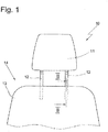
- the headrest 10 includes according to Fig. 1 a headrest part 11 which is mounted by means of support rods 12 to the structure of a backrest 13 of a vehicle seat 14, which is only partially shown.
- the support rods 12 are formed in the present embodiment as a pipe with a central axis m, but they can also be made of solid material according to an alternative embodiment. Instead of single support rods may alternatively also a support bar bracket be used. In this case, the support rods 12 are to be understood as free ends of the support bar bracket.
- bearing sleeves 15 are used, which are usually made of plastic.
- the bearing sleeves 15 are in Fig. 1 not shown.
- the bearing sleeves 15 prevent noise between the usually metallic backrest structure and the support rod 12 made of metal.
- the bearing sleeve 15 fit inaccuracies can be compensated.
- the bearing sleeve 15 has an inner surface 35, which - contrary to the representation in the Fig. 2 to 5 - Is in contact with an outer surface 36 of the support rod 12.
- the support rod 12 is directly in contact with the inner surface 35 of the bearing sleeve 15.
- the inner surface 35 may also form projections and / or ribs and / or elastic arms, which are in contact with the support rod 12.
- the invention is independent of the manner of storage and management of the support rod 12 on the bearing sleeve 15. Also on the shape of the support rod 12 is not important in the invention.
- the bearing sleeve 15 may be circular or even angular in cross section, for example.
- the bearing sleeve 15 is provided with a ring land 17 which projects radially outwardly beyond the bearing sleeve 15.
- a locking element 18 is divided so that a free end portion 19 is formed.
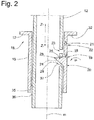
- the junction between the end portion 19 and the bearing sleeve 15 is formed for example as a film hinge joint 20, that is, the material of the wall of the bearing sleeve 15 is at this point of a thickness that movement of the locking element 18 between a in Fig. 2 shown assembly position and a in Fig. 5 shown locking position is possible.
- the locking element 18 is pivotable in the directions u1 and u2 between the mounting position and the locking position.
- the locking element 18 comprises a contact surface 24 which forms an acute angle in the mounting position with a movement direction z2 of the support rod 12. In this way, a region of the support rod 12 in a movement of the support rod 12 relative to the bearing sleeve 15 in the direction z2 exert a force on the locking element 18, which moves the locking element in the locking position.
- the first locking element further comprises a locking surface 25, which in the locking position according to Fig. 5 cooperates with a mating surface 26 of a backrest structure 27 to prevent movement of the bearing sleeve 15 in the direction x2 from the mounting seat by a lock.
- a projection 28 of the locking element 18 cooperates with the support rod 12 in a form-fitting manner in the mounting position and prevents unintentional movement out of the mounting position, e.g. in the latch position.
- the projection 28 is elastically deformable on exceeding a threshold force on the contact surface 24, so that the locking element 18 can be moved from the mounting position to the locking position.
- the locking element 18 also prevents the bearing sleeve 15 from moving out of a defined relative position to the support rod 12.
- the bearing sleeve 15 comprises a locking element 21.
- the locking element 21 is attached to the bearing sleeve 15.
- the locking element 21 is movable between a release position and a locking position and loaded by its elastic restoring force in the locking position.
- a separate spring could load the locking element 21 in the locking position.
- the locking element 21 may be arranged for example in a recess 22 of the bearing sleeve 15. Contrary to the illustration in Fig. 2 can the recess 22 instead of a breakthrough in the wall of the bearing sleeve 15 and a mere recess, so be a depression in the wall of the bearing sleeve 15.
- the locking element 21 is in engagement with a recess 23 of the support rod 12.
- the recess 23 may also be opposite to the representation in Fig. 2 instead of a breakthrough be a mere depression in the surface of the support rod 12, which is prepared for example by an impression in the wall of the support rod 12.
- the support rod 12 in the present embodiment according to Fig. 5 immovable in both directions z1 and z2 relative to the bearing sleeve 15.
- the support bar 12 can be moved relative to the bearing sleeve 15 in the directions z1 and z2 when the locking element 18 is in the locking position.
- the recess 23 may also be formed with an edge formed transversely to the direction of movement z2 edge and an obliquely to the direction of movement z1 shaped ramp that the support rod 12 in the Arretierposition immovable only in the direction z2 relative to the bearing sleeve 15, in the direction z1, however, is movable.
- the embodiment corresponds to Fig. 6 the first embodiment according to the Fig. 1 to 5
- a recess 29 is provided in the support rod 12 is - for engagement of the first locking element in the mounting position - a recess 29 is provided.
- the recess 29 may be contrary to the representation in Fig. 2 instead of one Breakthrough be a mere depression in the surface of the support rod 12, which was prepared for example by an impression in the wall of the support rod 12. Due to the recess 29, the locking element 18 can move into the mounting position.
- a positive connection between the support rod 12 and the bearing sleeve 15, which prevents the bearing sleeve 12 - eg during transport of the headrest 10 - from its relative position to the Support rod 12 moves.
- the assembly process can be carried out as follows.
- the finished manufactured headrest part 11 with the support rods 12 attached thereto is provided and on each support rod 12, a bearing sleeve 15 is attached and brought into the first relative position to the support rod 12.
- each free end is a support rod 12 in the sense of this application.
- the locking element 18 is moved into the mounting position, ie in engagement with the recess 29, wherein the projection 28 is positively engaged with a structure of the support rod 12 (see Fig. 2 ).
- the projection 28 with a soffit 37 of the recess 29 is engaged.
- the headrest 10 preassembled in this way can then be packaged and delivered to the assembly line of the automobile manufacturer.
- the structure 27 of the backrest 13 of the vehicle seat 14 is provided with mounting seats 30.
- Each mounting seat 30 is formed in the present embodiment of a sleeve 31, for example, a circular cylindrical in cross-section sleeve which is attached to the structure 27, for example by a welding operation.
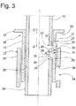
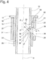
- the support rods 12 with the bearing sleeves 15 mounted thereon are moved in the direction of z1 in the mounting seat 30 (please refer Fig. 3 ), until each bearing sleeve 15 is arranged in a mounting seat 30 (see Fig. 4 ).
- the bearing sleeve 15 is arranged in the mounting seat 30 when a lower surface 32 of the annular web 17 rests on an end face 33 of the sleeve structure 31.
- the sleeve structure 31 comprises a recess 34, which is arranged approximately opposite the recess 29 of the support rod 12, when the support rod 12 is in the first relative position and the bearing sleeve 15 in the mounting seat 30.
- the support rod 12 is arranged relative to the bearing sleeve 15 in the second relative position and the locking element 18 is arranged in the locking position.
- the locking surface 25 is positioned relative to the mating surface 26 such that movement of the bearing sleeve 15 in the direction z2 is locked.
- the interaction of the lower surface 32 of the bearing sleeve 15 with the end face 33 of the backrest structure 27 prevents movement of the bearing sleeve 15 in the direction z1.
- a region 38 of the outer surface 36 of the support rod 12 prevents a return movement of the locking element 18 in the mounting position.
- the recess 23 is arranged to the locking member 21 so that it can move in the direction x in engagement with the recess 23, so that a movement of the support rod 12 in the directions z1 and z2 is locked relative to the bearing sleeve 15.
- the locking element 21 is in the direction x in engagement with the recess 23 loaded.
Landscapes
- Engineering & Computer Science (AREA)
- Aviation & Aerospace Engineering (AREA)
- Transportation (AREA)
- Mechanical Engineering (AREA)
- Chair Legs, Seat Parts, And Backrests (AREA)
- Seats For Vehicles (AREA)
Abstract
Description
- Die Erfindung betrifft gemäß einem ersten Aspekt eine Kopfstütze. Eine solche Kopfstütze ist aus offenkundiger Vorbenutzung bekannt. Sie umfasst ein Kopfanlageteil, an welchem Tragstangen gehalten sind, mit denen das Kopfanlageteil an der Struktur der Rückenlehne gelagert werden kann. Ferner umfasst die Kopfstütze rückenlehnenfeste Führungshülsen aus Kunststoff, in welche die Tragstangen einsteckt und mit diesen lösbar verriegelt sind. Eine Höhenverstellung findet z.B. durch eine Relativbewegung zwischen dem Kopfanlageteil und den Tragstangen oder zwischen den Tragstangen und den Führungshülsen statt.
- Die aus dem Stand der Technik bekannte Tragstange wurde montiert, indem die Führungshülse in einen Sitz an der Rückenlehne bewegt und dort verriegelt wurde. Die Verriegelung erfolgte z.B. durch Rastelemente der Führungshülse, die sich in Eingriff mit der Lehnenstruktur bewegten, wenn die Führungshülse in ihrem Sitz angeordnet war. Danach wurden die Tragstangen in den Führungshülsen montiert. Die Tragstangen verhinderten, dass die Riegelelemente der Führungshülsen sich in den Innenraum der Führungshülse außer Eingriff mit der Struktur der Rückenlehne bewegen konnten.
- Viele Komponenten des Fahrzeugs, wie z.B. die Kopfstützen, werden heute nicht immer von den Automobilherstellern selbst, sondern von Zulieferfirmen produziert und anschließend zur Montage an den Automobilhersteller geliefert.
- Die Aufgabe der Erfindung besteht darin eine Vorrichtung zu schaffen, mit welcher die Montage der Kopfstütze an der Rückenlehne eines Fahrzeugsitzes einfacher durchführbar ist.
- Die Aufgabe wurde gelöst durch eine Kopfstütze mit den Merkmalen des Anspruchs 1.
- Die erfindungsgemäße Kopfstützenvorrichtung umfasst ein Kopfanlageteil an welchem wenigstens eine Tragstange unbewegbar oder relativbeweglich zu dem Kopfanlageteil gehalten ist. Mit der Tragstange ist das Kopfanlageteil an der Rückenlehne eines Fahrzeugsitzes lagerbar. Ferner umfasst die Kopfstützenvorrichtung eine Lagerhülse in welcher die Tragstange gelagert ist. Die Lagerhülse ist an der Struktur der Rückenlehne (nachfolgend Lehnenstruktur genannt) befestigbar.
- Die Lagerhülse weist ein Riegelelement auf, welches zwischen einer Riegelposition, in welcher das Riegelelement über eine Außenfläche der Lagerhülse hinaus vorsteht und mit der Lehnenstruktur in Eingriff ist, und einer Montageposition bewegbar ist, in welcher das Riegelelement in Bezug auf die Riegelposition weniger über eine Außenfläche der Führungshülse vorragt. In der Montageposition überragt z.B. das Riegelelement die Außenfläche der Lagerhülse nicht oder lediglich geringfügig. Die Lagerhülse kann dann in einen Lagerssitz der Lehnenstruktur bewegt werden. In der Riegelposition ist die Lagerhülse fest mit der Lehnenstruktur verbunden.
- Die Kopfstütze kann ohne Höhenverstellung ausgebildet sein. In diesem Fall kann weder die Tragstange relativ zu der Rückenlehne, noch das Kopfanlageteil relativ zu der Tragstange bewegt werden. Gemäß einer alternativen Ausführung ist die Kopfstütze mit einer Höhenverstellung versehen, wobei das Kopfanlageteil relativ zu der Tragstange bewegbar ist. Gemäß einer anderen Ausführung ist die Kopfstütze mit einer Höhenverstellung versehen, wobei die Tragstange relativ zu der Lagerhülse bewegbar ist.
- Die erfindungsgemäße Kopfstütze ist derart ausgebildet, dass die Führungshülse während der Montage auf die Tragstange aufgeschoben werden kann und die Kopfstütze, d.h. Kopfanlageteil mit Tragstangen und Führungshülsen gemeinsam, an der Struktur der Rückenlehne montiert werden kann.
- Die Tragstangen weisen z.B. eine Aussparung auf, in welche das Riegelelement der Führungshülse in der Montageposition zurückweichen kann, wenn die Führungshülse in den Sitz der Rückenlehnenstruktur bewegt wird. Die Begriffe Aussparung und Ausnehmung bezeichnen im Sinne der Erfindung sowohl einen Materialabtrag, als auch eine durch Materialverformung hergestellte Einsenkung. Die Begriffe können darüber hinaus sowohl Öffnungen, als auch geschlossene Vertiefungen bezeichnen.
- Das Riegelelement ist z.B. durch eine Relativbewegung zwischen der Tragstange und der Lagerhülse von der Tragstange aus der Montageposition in die Riegelposition bewegbar. D. h., dass das Riegelelement von einer auf die Tragstange oder auf die Lagerhülse wirkenden Kraft in die Riegelposition bewegt werden kann.
- Z.B. weist das Riegelelement eine Kontaktfläche auf, die in der Montageposition schräg zu einer Bewegungsbahn der Tragstange angeordnet ist, so dass bei dem Kontakt zwischen Tragstange und Riegelelement eine in axialer Richtung der Tragstange wirkende Kraft auf das Riegelelement übertragbar und in eine radiale Kraft umlenkbar ist, um das Riegelelement in die Riegelposition zu bewegen.
- Gemäß einer alternativen Ausführungsform wird das Riegelelement z.B. von einem gesonderten Stellelement zwischen der Montageposition und der Riegelposition verstellt.
- Das Riegelelement umfasst z.B. eine Riegelfläche, die in der Riegelposition mit einer Gegenfläche der Lehnenstruktur zusammenwirkt und eine Bewegung der Lagerhülse in Demontagerichtung der Lagerhülse verhindert. Wenn das Riegelelement - z.B. aufgrund einer Relativbewegung zwischen der Tragstange und der Lagerhülse - in die Riegelposition bewegt wird, wird die Riegelfläche derart relativ zu der Gegenfläche angeordnet, dass das Zusammenwirken von Riegelfläche und Gegenfläche eine Relativbewegung zwischen Lagerhülse und Lehnenstruktur in wenigstens eine Richtung verhindert.
- Das Riegelelement ist z.B. einstückig mit der Lagerhülse ausgebildet. Es kann z.B. derart an der Lagerhülse angeformt sein, dass es bewegbar ist. Z.B. kann zwischen dem Riegelelement und der Lagerhülse ein Filmscharnier ausgebildet sein. Filmscharnier bedeutet z.B., dass das Material an dieser Stelle eine geringere Dicke aufweist, die eine Bewegbarkeit lediglich an dieser Stelle ermöglicht.
- Das Riegelelement ist z.B. in die Montageposition oder in die Riegelposition rückstellbelastet. Die Rückstellung kann von einer separaten Feder oder von der elastischen Rückstellkraft des Materials vorgenommen werden. Wenn das Riegelelement in die Riegelposition belastet ist, bewegt es sich z.B. nicht selbständig in die Montageposition zurück. D.h. nach der Montage der Lagerhülse befindet sich das Riegelelement in der Riegelposition und kann die Bewegbarkeit der Tragstange in der Lagerhülse nicht beeinträchtigen.
- Zusammenwirkende Formschlussmittel, die an der Tragstange und an dem Riegelelement ausgebildet sind, verhindern z.B. lösbar ein ungewolltes Bewegen des Riegels von der Montageposition in die Riegelposition.
- Die Lagerhülse umfasst z.B. ein Arretierelement, welches mit einem Gegenelement der Tragstange in Eingriff bringbar ist, um eine axiale Relativbewegung zwischen Lagerhülse und Tragstange in wenigstens eine Richtung zu verhindern. Das Arretierelement wirkt z.B. in herkömmlicher Weise mit einer Rastkerbe zusammen. In einer Arretierposition steht das Arretierelement in Eingriff mit der Rastkerbe und verhindert z.B. eine Bewegung der Tragstange relativ zu der Lagerhülse in wenigstens eine Bewegungsrichtung, z.B. in zwei entgegengesetzte Bewegungsrichtungen. Das Arretierelement ist z.B. in eine Löseposition bewegbar, in welcher die Tragstange relativ zu der Lagerhülse verlagerbar ist.
- Z.B. kann in wenigstens einer ersten Relativposition zwischen Lagerhülse und Tragstange das Riegelelement in der Montageposition angeordnet werden, wobei in wenigstens einer zweiten Relativposition die Tragstange eine Bewegung des Riegelelements aus der Riegelposition in die Montageposition verhindert. Auf diese Weise kann die Baugruppe umfassend das Kopfanlageteil, die Tragstangen und die auf den Tragstangen montierten Lagerhülsen in den Montagesitzen der Lehnenstruktur montiert werden. Durch eine darauf folgende Bewegung von der ersten Relativposition in die zweite Relativposition wird z.B. verhindert, dass sich das Riegelelement zurück in die Montageposition bewegt. Bei der Bewegung von der ersten Relativposition in die zweite Relativposition wird z.B. das Riegelelement von der Montageposition in die Riegelposition bewegt. In der zweiten Relativposition verhindert z.B. eine Wand der Tragstange die Rückbewegung des Riegelelements in die Montageposition.
- Z.B. ist in der zweiten Relativposition das Arretierelement derart zu dem Gegenelement angeordnet, dass es in die Arretierposition bewegbar ist.
- Die Erfindung betrifft außerdem ein Verfahren zur Montage einer Kopfstütze.
- Ein solches Verfahren ist aus offenkundiger Vorbenutzung bekannt. Es wird Bezug genommen auf den zu dem ersten Erfindungsaspekt beschriebenen Stand der Technik.
- Es war Aufgabe der Erfindung ein Verfahren zu schaffen, mit welchem die Montage der Kopfstütze vereinfacht werden kann.
- Die Aufgabe wurde gelöst durch ein Verfahren zur Montage einer Kopfstütze mit den Merkmalen des Anspruchs 8.
- Bei dem Verfahren wird ein Kopfanlageteil verwendet, an welchem zur Lagerung an einer Lehnenstruktur eines Fahrzeugsitzes wenigstens eine Tragstange relativbeweglich oder unbewegbar befestigt ist. Auf die Tragstange wird jeweils eine Lagerhülse aufgesteckt, z.B. derart, dass ein in der Montageposition angeordnetes Riegelelement in eine Aussparung der Tragstange hineinragt und auf diese Weise nicht über eine Außenfläche der Tragstange vorragt. Die so vormontierte Baugruppe kann dann zur Montage an dem Fahrzeugsitz geliefert werden. Anschließend wird die Lagerhülse samt dem Kopfanlageteil und der daran befestigten Tragstange in einem Montagesitz der Lehnenstruktur angeordnet. Danach wird das Riegelelement aus der Montageposition in die Riegelposition bewegt, in welcher eine Relativbewegung zwischen der Lagerhülse und der Sitzstruktur zumindest in Demontagerichtung verriegelt ist.
- Z.B. wird die Tragstange nach der Anordnung der Lagerhülse in dem Montagesitz von einer ersten Relativposition in eine zweite Relativposition bewegt. Durch diese Relativbewegung kann das Riegelelement aus der Montageposition in die Riegelposition bewegt werden. Gemäß einer Alternative kann aber auch eine Rückstellkraft die Bewegung in die Riegelposition bewirken. Das kann z.B. auch die elastische Rückstellkraft des Materials sein, insbesondere da z.B. die Bewegung von der Montageposition in die Riegelposition in der Regel lediglich einmal, allenfalls wenige Male, stattfindet.
- Alternativ oder zusätzlich kann die Relativbewegung bewirken, dass das Riegelelement in der Riegelposition gesichert wird. Die Sicherung kann z.B. dadurch erfolgen, dass die Tragstangenaußenfläche eine Bewegung des Riegelelements aus der Riegelposition in die Montageposition verhindert.
- Alternativ oder zusätzlich kann die Relativbewegung bewirken, dass in der zweiten Relativposition das Arretierelement der Lagerhülse von einer Löseposition in eine Arretierposition bewegbar ist, wobei in der Löseposition eine Bewegung der Tragstange relativ zu der Lagerhülse möglich ist und in der Arretierposition das Arretierelement in ein Gegenelement der Tragstange eingreift und somit eine Relativbewegung der Tragstange in Bezug auf die Lagerhülse in wenigstens eine Richtung, insbesondere in zwei Richtungen, verriegelt.
- Weitere Vorteile der Erfindung ergeben sich anhand eines in den Fig. schematisch dargestellten Ausführungsbeispiels. Es zeigen:
-
Fig. 1 eine Frontdarstellung der Rückenlehne eines Fahrzeugsitzes mit daran gelagerter Kopfstütze, -
Fig. 2 eine Schnittdarstellung einer Tragstange der Kopfstütze mit darauf montierter Lagerhülse, wobei ein Riegelelement der Lagerhülse in einer Montageposition angeordnet ist, -
Fig. 3 eine Schnittdarstellung der Baugruppe gemäßFig. 2 , wobei die Tragstange mit der Lagerhülse in einen Montagesitz einer Lehnenstruktur hineinbewegt wird, -
Fig. 4 die Schnittdarstellung in Anlehnung anFig. 3 , wobei die Lagerhülse in dem Montagesitz angeordnet ist, -
Fig. 5 die Schnittdarstellung in Anlehnung anFig. 4 , wobei das Riegelelement in einer Riegelposition in Eingriff mit einer Gegenfläche der Lehnenstruktur steht und wobei ein Arretierelement der Lagerhülse in einer Arretierposition in Eingriff mit einem Gegenelement der Tragstange angeordnet ist, -
Fig. 6 die Schnittdarstellung in Anlehnung anFig. 5 gemäß einem anderen Ausführungsbeispiel, wobei das Gegenelement derart ausgebildet ist, dass eine Bewegung der Tragstange in eine erste Richtung verhindert wird, in eine zweite, entgegengesetzte Richtung aber möglich ist. - In den Fig. ist eine Kopfstützenvorrichtung insgesamt mit dem Bezugszeichen 10 bezeichnet. Gleiche Bezugszeichen in den unterschiedlichen Fig. bezeichnen entsprechende Teile, auch wenn kleine Buchstaben nachgestellt oder weggelassen sind.
- Die Kopfstütze 10 umfasst gemäß
Fig. 1 ein Kopfanlageteil 11, welches mittels Tragstangen 12 an der Struktur einer lediglich teilweise dargestellten Rückenlehne 13 eines Fahrzeugsitzes 14 gelagert ist. Die Tragstangen 12 sind im vorliegenden Ausführungsbeispiel als Rohr mit einer Mittelachse m ausgebildet, sie können aber gemäß einer alternativen Ausführung auch aus Vollmaterial hergestellt sein. Anstelle von Einzeltragstangen kann alternativ auch ein Tragstangenbügel verwendet werden. In diesem Fall sind die Tragstangen 12 als freie Enden des Tragstangenbügels zu verstehen. - Zur Halterung der Tragstangen 12 an einer Stuktur der Rückenlehne 13 werden Lagerhülsen 15 verwendet, die üblicherweise aus Kunststoff gefertigt sind. Die Lagerhülsen 15 sind in
Fig. 1 nicht dargestellt. Die Lagerhülsen 15 verhindern Geräusche zwischen der in der Regel metallischen Lehnenstruktur und der aus Metall hergestellten Tragstange 12. Darüber hinaus können mit der Lagerhülse 15 Passungsungenauigkeiten ausgeglichen werden. - Die Lagerhülse 15 weist eine Innenfläche 35 auf, die - entgegen der Darstellung in den
Fig. 2 bis 5 - mit einer Außenfläche 36 der Tragstange 12 in Kontakt steht. Im vorliegenden Ausführungsbeispiel steht die Tragstange 12 unmittelbar mit der Innenfläche 35 der Lagerhülse 15 in Kontakt. Gemäß einer Alternative kann die Innenfläche 35 aber auch Vorsprünge oder / und Rippen oder / und elastische Arme ausbilden, die mit der Tragstange 12 in Kontakt stehen. Die Erfindung ist unabhängig von der Art und Weise der Lagerung und Führung der Tragstange 12 an der Lagerhülse 15. Auch auf die Form der Tragstange 12 kommt es bei der Erfindung nicht an. Die Lagerhülse 15 kann z.B. im Querschnitt kreisförmig oder auch eckig sein. - An einem Endbereich 16 ist die Lagerhülse 15 mit einem Ringsteg 17 versehen, der radial nach außen über die Lagerhülse 15 vorragt. Aus der Wand der Lagerhülse 15 ist ein Riegelelement 18 derart abgeteilt, dass ein freier Endbereich 19 ausgebildet ist. Die Verbindungstelle zwischen dem Endbereich 19 und der Lagerhülse 15 ist z.B. als Filmscharniergelenk 20 ausgebildet, d.h. das Material der Wand der Lagerhülse 15 ist an dieser Stelle von einer Dicke, dass eine Bewegung des Riegelelements 18 zwischen einer in
Fig. 2 dargestellten Montageposition und einer inFig. 5 dargestellten Riegelposition möglich ist. Im vorliegenden Ausführungsbeispiel ist das Riegelelement 18 in die Richtungen u1 und u2 zwischen der Montageposition und der Riegelposition schwenkbar. - Das Riegelelement 18 umfasst eine Kontaktfläche 24, die in der Montageposition mit einer Bewegungsrichtung z2 der Tragstange 12 einen spitzen Winkel bildet. Auf diese Weise kann ein Bereich der Tragstange 12 bei einer Bewegung der Tragstange 12 relativ zu der Lagerhülse 15 in Richtung z2 eine Kraft auf das Riegelelement 18 ausüben, welche das Riegelelement in die Riegelposition bewegt.
- Das erste Riegelelement umfasst des Weiteren eine Riegelfläche 25, die in der Riegelposition gemäß
Fig. 5 mit einer Gegenfläche 26 einer Lehnenstruktur 27 zusammenwirkt, um eine Bewegung der Lagerhülse 15 in Richtung x2 aus dem Montagesitz durch eine Verriegelung zu verhindern. - Ein Vorsprung 28 des Riegelelements 18 wirkt in der Montageposition formschlüssig mit der Tragstange 12 zusammen und verhindert eine unbeabsichtigte Bewegung aus der Montageposition heraus, z.B. in die Riegelposition. Der Vorsprung 28 ist bei Überschreitung einer Schwellenkraft auf die Kontaktfläche 24 elastisch verformbar, so dass sich das Riegelelement 18 aus der Montageposition in die Riegelposition bewegen lässt. In der Montageposition verhindert das Riegelelement 18 außerdem, dass sich die Lagerhülse 15 aus einer definierten Relativposition zu der Tragstange 12 herausbewegt.
- Außerdem umfasst die Lagerhülse 15 ein Arretierelement 21. Das Arretierelement 21 ist an der Lagerhülse 15 befestigt. Das Arretierelement 21 ist zwischen einer Löseposition und einer Arretierposition bewegbar und von seiner elastischen Rückstellkraft in die Arretierposition belastet. Gemäß einer Alternative könnte auch eine separate Feder das Arretierelement 21 in die Arretierposition belasten. In der Löseposition, gemäß
Fig. 2 , kann das Arretierelement 21 z.B. in einer Aussparung 22 der Lagerhülse 15 angeordnet sein. Entgegen der Darstellung inFig. 2 kann die Aussparung 22 anstelle eines Durchbruchs in der Wand der Lagerhülse 15 auch ein bloßer Rücksprung, also eine Vertiefung in der Wand der Lagerhülse 15 sein. - In der Arretierposition (siehe
Fig. 5 ) ist das Arretierelement 21 in Eingriff mit einer Ausnehmung 23 der Tragstange 12. Die Ausnehmung 23 kann ebenfalls entgegen der Darstellung inFig. 2 anstelle eines Durchbruchs eine bloße Vertiefung in der Oberfläche der Tragstange 12 sein, die z.B. durch eine Einprägung in der Wand der Tragstange 12 hergestellt wird. In der Arretierposition ist die Tragstange 12 bei dem vorliegenden Ausführungsbeispiel gemäßFig. 5 in beide Richtungen z1 und z2 relativ zu der Lagerhülse 15 unbewegbar. In der Löseposition kann die Tragstange 12 relativ zu der Lagerhülse 15 in die Richtungen z1 und z2 bewegt werden, wenn sich das Riegelelement 18 in der Riegelposition befindet. - Nach einem alternativen Ausführungsbeispiel gemäß
Fig. 6 könnte, z.B. wenn eine Höhenverstellvorrichtung eine Relativbewegbarkeit zwischen der Tragstange 12 und der Lagerhülse 15 vorsieht, die Ausnehmung 23 auch derart mit einer quer zu der Bewegungsrichtung z2 geformten Kante und einer schräg zu der Bewegungsrichtung z1 geformten Rampe ausgebildet sein, dass die Tragstange 12 in der Arrtierposition lediglich in Richtung z2 relativ zu der Lagerhülse 15 unbewegbar, in Richtung z1 jedoch bewegbar ist. Ansonsten entspricht das Ausführungsbeispiel gemäßFig. 6 dem ersten Ausführungsbeispiel gemäß derFig. 1 bis 5 - In der Tragstange 12 ist - zum Eingriff des ersten Riegelelementes in der Montageposition - eine Aussparung 29 vorgesehen. Auch die Aussparung 29 kann entgegen der Darstellung in
Fig. 2 anstelle eines Durchbruchs eine bloße Vertiefung in der Oberfläche der Tragstange 12 sein, die z.B. durch eine Einprägung in der Wand der Tragstange 12 hergestellt wurde. Aufgrund der Aussparung 29 kann sich das Riegelelement 18 in die Montageposition bewegen. Darüber hinaus besteht in der Montageposition aufgrund des Eingriffes des Riegelelements 18 in die Aussparung 29 eine formschlüssige Verbindung zwischen der Tragstange 12 und der Lagerhülse 15, die verhindert, dass sich die Lagerhülse 12 - z.B. während des Transports der Kopfstütze 10 - aus ihrer Relativposition zu der Tragstange 12 bewegt. - Das Montageverfahren kann folgendermaßen durchgeführt werden.
- Das fertig hergestellte Kopfanlageteil 11 mit den daran befestigten Tragstangen 12 wird bereitgestellt und auf jede Tragstange 12 wird eine Lagerhülse 15 aufgesteckt und in die erste Relativposition zu der Tragstange 12 gebracht. Bei Verwendung eines Tragstangenbügels ist jedes freies Ende eine Tragstange 12 im Sinne dieser Anmeldung. Das Riegelelement 18 wird in die Montageposition, d.h. in Eingriff mit der Aussparung 29 bewegt, wobei der Vorsprung 28 formschlüssig mit einer Struktur der Tragstange 12 in Eingriff ist (siehe
Fig. 2 ). Im vorliegenden Ausführungsbeispiel ist der Vorsprung 28 mit einer Laibung 37 der Aussparung 29 in Eingriff. - Die auf diese Weise vormontierte Kopfstütze 10 kann dann verpackt und an das Montageband des Automobilherstellers geliefert werden.
- Die Struktur 27 der Rückenlehne 13 des Fahrzeugsitzes 14 ist mit Montagesitzen 30 versehen. Jeder Montagesitz 30 wird im vorliegenden Ausführungsbeispiel von einer Hülse 31 gebildet, z.B. einer im Querschnitt kreiszylindrischen Hülse, die an der Struktur 27 befestigt ist, z.B. durch einen Schweißvorgang. Die Tragstangen 12 mit den darauf montierten Lagerhülsen 15 werden in Richtung z1 in den Montagesitz 30 bewegt (siehe
Fig. 3 ), bis jede Lagerhülse 15 in einem Montagesitz 30 angeordnet ist (sieheFig. 4 ). Die Lagerhülse 15 ist in dem Montagesitz 30 angeordnet, wenn eine Unterfläche 32 des Ringstegs 17 auf einer Stirnfläche 33 des der Hülsenstruktur 31 aufliegt. - Die Hülsenstruktur 31 umfasst eine Aussparung 34, die der Aussparung 29 der Tragstange 12 etwa gegenüberliegend angeordnet ist, wenn sich die Tragstange 12 in der ersten Relativposition und die Lagerhülse 15 in dem Montagesitz 30 befindet. Indem die Tragstange 12 anschließend relativ zu der Lagerhülse 15 in Richtung z2 bewegt wird, hat das Zusammenwirken der Wand der Tragstange 12 mit der Kontaktfläche 24 zur Folge, dass sich der Vorsprung 28 aus dem Eingriff mit der Gegenstruktur der Tragstange 12 bewegt und das Riegelelement 18 in die Riegelposition gemäß
Fig. 5 bewegt wird. Z.B. steht eine Laibung 37 der Aussparung 29 mit der Kontaktfläche 24 in Kontakt und bewegt das Riegelelement 18. - In
Fig. 5 ist die Tragstange 12 relativ zu der Lagerhülse 15 in der zweiten Relativposition angeordnet und das Riegelelement 18 ist in der Riegelposition angeordnet. In der Riegelposition gemäßFig. 5 ist die Riegelfläche 25 derart zu der Gegenfläche 26 positioniert, dass eine Bewegung der Lagerhülse 15 in Richtung z2 verriegelt ist. Das Zusammenwirken der Unterfläche 32 der Lagerhülse 15 mit der Stirnfläche 33 der Lehnenstruktur 27 verhindert eine Bewegung der Lagerhülse 15 in Richtung z1. Ein Bereich 38 der Außenfläche 36 der Tragstange 12 verhindert eine Rückbewegung des Riegelelements 18 in die Montageposition. Außerdem ist die Ausnehmung 23 derart zu dem Arretierelement 21 angeordnet, dass es sich in Richtung x in Eingriff mit der Aussparung 23 bewegen kann, so dass eine Bewegung der Tragstange 12 in die Richtungen z1 und z2 relativ zu der Lagerhülse 15 verriegelt ist. Z.B. ist das Arretierelement 21 in Richtung x in Eingriff mit der Aussparung 23 belastet. Die Kopfstütze 10 ist damit fertig montiert und fest an der Struktur 27 der Rückenlehne 13 gehalten.
Claims (11)
- Kopfstütze (10) mit einem Kopfanlageteil (11) an welchem wenigstens eine Tragstange (12) zur Lagerung an der Rückenlehne (13) eines Fahrzeugsitzes (14) unbewegbar oder relativbeweglich zu dem Kopfanlageteil (11) gehalten ist, mit einer Lagerhülse (15) in welcher die Tragstange (12) gelagert ist, wobei die Lagerhülse (15) zu ihrer Verriegelung an einer Struktur (27) des Fahrzeugsitzes (14) ein Riegelelement (18) aufweist, welches zwischen einer Riegelposition, in welcher das Riegelelement (18) über eine Außenfläche (36) der Lagerhülse (15) vorragt und einer Montageposition bewegbar ist, in welcher es bezüglich der Riegelposition weniger über eine Außenfläche (36) der Lagerhülse (15) vorragt.
- Kopfstütze nach Anspruch 1, dadurch gekennzeichnet, dass die Tragstange (12) eine Aussparung (29) umfasst, in welche das Riegelelement (18) sich in der Montageposition hineinbewegen kann.
- Kopfstütze nach Anspruch 1 oder 2, dadurch gekennzeichnet, dass das Riegelelement (18) eine Kontaktfläche (24) aufweist, die mit einer Fläche der Tragstange (12) zusammenwirkt, wobei das Riegelelement (18) durch eine Relativbewegung zwischen der Tragstange (12) und der Lagerhülse (15) von der Tragstange (12) in die Riegelposition bewegbar ist.
- Kopfstütze nach Anspruch 3, dadurch gekennzeichnet, dass die Kontaktfläche (24) in der Montageposition schräg zu einer Bewegungsrichtung (z2) der Tragstange (12) angeordnet ist, so dass bei dem Kontakt zwischen Tragstange (12) und Riegelelement (18) eine in axialer Richtung der Tragstange (12) wirkende Kraft auf das Riegelelement (18) übertragbar und in eine radiale Kraft umlenkbar ist, um das Riegelelement (18) in die Riegelposition zu bewegen.
- Kopfstütze nach einem der vorangehenden Ansprüche, dadurch gekennzeichnet, dass das Riegelelement (18) eine Riegelfläche (25) umfasst, die in der Riegelposition mit einer Gegenfläche (26) der Lehnenstruktur (27) zusammenwirkt und eine Bewegung der Lagerhülse (15) in Demontagerichtung (z2) der Lagerhülse (15) verhindert.
- Kopfstütze nach einem der vorangehenden Ansprüche, dadurch gekennzeichnet, dass in wenigstens einer ersten Relativposition zwischen Lagerhülse (15) und Tragstange (12) das Riegelelement (18) in der Montageposition angeordnet werden kann und dass in wenigstens einer zweiten Relativposition die Tragstange (12) eine Bewegung aus der Riegelposition in die Montageposition verhindert.
- Kopfstütze nach einem der vorangehenden Ansprüche, dadurch gekennzeichnet, dass die Lagerhülse (15) ein Arretierelement (21) umfasst, welches mit einer Ausnehmung (23) der Tragstange (12) in Eingriff bringbar ist, um eine axiale Relativbewegung zwischen Lagerhülse (15) und Tragstange (12) in wenigstens eine Richtung (z2) zu verhindern.
- Verfahren zur Montage einer Kopfstütze (10) an der Struktur (27) einer Rückenlehne (13) eines Fahrzeugsitzes (14), umfassend die Schritte
Aufstecken einer Lagerhülse (15) auf wenigstens eine Tragstange (12) in eine erste Relativposition, derart, dass ein Riegelelement (18) der Lagerhülse (15) in einer Montageposition angeordnet wird, in welcher das Riegelelement (18) in eine Aussparung (29) der Tragstange (12) hineinragt und eine Riegelfläche (25) des Riegelelements (18) in Bezug auf eine Riegelposition weniger über eine Außenfläche (36) der Lagerhülse (15) vorragt,
Einstecken der Lagerhülse (15) samt des Kopfanlageteils (11) und der daran befestigten Tragstange (12) in einen Montagesitz (30) der Struktur (27),
Bewegen des Riegelelements (18) aus der Montageposition in die Riegelposition, in welcher das Riegelelement (18) über eine Außenfläche (36) der Lagerhülse (15) vorragt und eine Riegelfläche (25) des Riegelelements (18) mit einer Gegenfläche (26) der Struktur (27) verriegelnd zusammenwirkt. - Verfahren nach Anspruch 8, gekennzeichnet durch eine Relativbewegung zwischen der Tragstange (12) und der Lagerhülse (15) von einer ersten Relativposition in eine zweite Relativposition.
- Verfahren nach Anspruch 9, dadurch gekennzeichnet, dass das Riegelelement während der Bewegung zwischen der ersten Relativposition und der zweiten Relativposition von der Tragstange (12) in die Riegelposition bewegt wird.
- Verfahren nach Anspruch 9 oder 10, dadurch gekennzeichnet, dass in der zweiten Relativposition ein Arretierelement (21) der Lagerhülse (15) in Eingriff mit einer Ausnehmung (23) der Tragstange (12) bewegt wird, um eine axiale Bewegung der Tragstange (12) relativ zu der Lagerhülse (15) zu verhindern.
Applications Claiming Priority (1)
| Application Number | Priority Date | Filing Date | Title |
|---|---|---|---|
| DE102017004485.6A DE102017004485B3 (de) | 2017-05-10 | 2017-05-10 | Kopfstütze und Verfahren zur Montage einer Kopfstütze |
Publications (2)
| Publication Number | Publication Date |
|---|---|
| EP3406482A1 true EP3406482A1 (de) | 2018-11-28 |
| EP3406482B1 EP3406482B1 (de) | 2020-08-26 |
Family
ID=61868461
Family Applications (1)
| Application Number | Title | Priority Date | Filing Date |
|---|---|---|---|
| EP18165466.6A Active EP3406482B1 (de) | 2017-05-10 | 2018-04-03 | Kopfstütze und verfahren zur montage einer kopfstütze |
Country Status (2)
| Country | Link |
|---|---|
| EP (1) | EP3406482B1 (de) |
| DE (1) | DE102017004485B3 (de) |
Cited By (2)
| Publication number | Priority date | Publication date | Assignee | Title |
|---|---|---|---|---|
| CN112450634A (zh) * | 2020-06-24 | 2021-03-09 | 延锋安道拓座椅有限公司 | 一种双锁止头枕导套结构 |
| CN115675230A (zh) * | 2021-07-28 | 2023-02-03 | 格瑞玛股份公司 | 保持件、头枕装置和用于安装保持件的方法 |
Citations (3)
| Publication number | Priority date | Publication date | Assignee | Title |
|---|---|---|---|---|
| US20030222491A1 (en) * | 2002-05-29 | 2003-12-04 | Centura Group, Inc. | Head restraint assembly for motor vehicle |
| DE69928345T2 (de) * | 1998-09-29 | 2006-08-10 | Piolax Inc., Yokohama | Tragstruktur für Kopfstütze |
| DE602006000827T2 (de) * | 2005-01-26 | 2009-04-16 | I.T.W. De France | Hülle zur Aufnahme einer Kopfstützenführungsstange |
Family Cites Families (2)
| Publication number | Priority date | Publication date | Assignee | Title |
|---|---|---|---|---|
| DE102013005246B4 (de) | 2013-03-27 | 2023-08-10 | Grammer Aktiengesellschaft | Lagervorrichtung sowie Fahrzeugsitz mit einer Lagervorrichtung |
| DE102013009469B4 (de) | 2013-06-06 | 2018-07-26 | Grammer Aktiengesellschaft | Kopfstütze |
-
2017
- 2017-05-10 DE DE102017004485.6A patent/DE102017004485B3/de active Active
-
2018
- 2018-04-03 EP EP18165466.6A patent/EP3406482B1/de active Active
Patent Citations (3)
| Publication number | Priority date | Publication date | Assignee | Title |
|---|---|---|---|---|
| DE69928345T2 (de) * | 1998-09-29 | 2006-08-10 | Piolax Inc., Yokohama | Tragstruktur für Kopfstütze |
| US20030222491A1 (en) * | 2002-05-29 | 2003-12-04 | Centura Group, Inc. | Head restraint assembly for motor vehicle |
| DE602006000827T2 (de) * | 2005-01-26 | 2009-04-16 | I.T.W. De France | Hülle zur Aufnahme einer Kopfstützenführungsstange |
Cited By (3)
| Publication number | Priority date | Publication date | Assignee | Title |
|---|---|---|---|---|
| CN112450634A (zh) * | 2020-06-24 | 2021-03-09 | 延锋安道拓座椅有限公司 | 一种双锁止头枕导套结构 |
| CN112450634B (zh) * | 2020-06-24 | 2023-12-01 | 延锋国际座椅系统有限公司 | 一种双锁止头枕导套结构 |
| CN115675230A (zh) * | 2021-07-28 | 2023-02-03 | 格瑞玛股份公司 | 保持件、头枕装置和用于安装保持件的方法 |
Also Published As
| Publication number | Publication date |
|---|---|
| EP3406482B1 (de) | 2020-08-26 |
| DE102017004485B3 (de) | 2018-06-14 |
Similar Documents
| Publication | Publication Date | Title |
|---|---|---|
| EP3045347B1 (de) | Lagervorrichtung und kopfstütze | |
| DE102015011477B4 (de) | Kopfstütze | |
| EP2910319B1 (de) | Tragvorrichtung | |
| EP3293043A1 (de) | Fahrzeugsitz | |
| DE102011112418A1 (de) | Vorrichtung zur Befestigung einer Kopfstütze an einem Fahrzeugsitz und Fahrzeugsitz mit Kopfstütze | |
| DE102014103801B3 (de) | Rückenlehne für ein Kraftfahrzeug mit wenigstens zwei unabhängig voneinander verschwenkbaren Lehnenteilen | |
| DE102018121594B4 (de) | Halterung zur Verbindung eines Kindersitzes mit einem klappbaren Fahrzeugsitz | |
| EP3406482B1 (de) | Kopfstütze und verfahren zur montage einer kopfstütze | |
| DE112022000583T5 (de) | Halterungseinsatz für eine kopfstützenhülsenvorrichtung, eine hülsenvorrichtungsbaugruppe davon | |
| EP3144185A1 (de) | Abdeckvorrichtung zur anordnung in einem kraftfahrzeug sowie verfahren zu deren herstellung | |
| DE102010048956A1 (de) | Vorrichtung und Verfahren zur Befestigung eines mindestens eine Öffnung aufweisenden Bauteils an einem Trägerteil | |
| DE102021119621A1 (de) | Halteteil zur Lagerung einer Kopfstütze sowie Kopfstützenvorrichtung mit wenigstens einem Halteteil und Verfahren zur Montage eines Halteteils | |
| EP3392078B1 (de) | Gelenkvorrichtung, ausstattungsvorrichtung eines fahrzeuginnenraums umfassend eine gelenkvorrichtung sowie ein verfahren zur montage der gelenkvorrichtung | |
| EP2839987B1 (de) | Tragstangenbügel, Kopfstütze und Verfahren zur Montage | |
| EP3059117B1 (de) | Kopfstütze | |
| DE10145240A1 (de) | Kopfstütze für Fahrzeugsitze | |
| DE3731409A1 (de) | Elektromotor, insbesondere elektrischer kleinmotor | |
| DE2101047C3 (de) | Scheibenwischer | |
| DE69404908T2 (de) | Scheibenwischer mit gelenkig verbundenen Elementen | |
| DE102005005826B4 (de) | Kopfstütze | |
| EP3045617B1 (de) | Rosette und anordnung eines tür- oder fensterdrückers und einer rosette an einer aufnahmeöffnung eines türblatts, eines fensterblatts oder dergleichen | |
| DE102011050540B4 (de) | Kopfstütze für Kraftfahrzeugsitz | |
| DE102019208534B4 (de) | Kopfstützenhalterung und Kopfstützenanordnung | |
| DE102018209413B4 (de) | Tragvorrichtung für eine Schutzvorrichtung eines Kraftfahrzeugs | |
| DE102006059096A1 (de) | Baugruppe zur fahrzeugseitigen Befestigung eines Gurtschlosses |
Legal Events
| Date | Code | Title | Description |
|---|---|---|---|
| PUAI | Public reference made under article 153(3) epc to a published international application that has entered the european phase |
Free format text: ORIGINAL CODE: 0009012 |
|
| STAA | Information on the status of an ep patent application or granted ep patent |
Free format text: STATUS: THE APPLICATION HAS BEEN PUBLISHED |
|
| AK | Designated contracting states |
Kind code of ref document: A1 Designated state(s): AL AT BE BG CH CY CZ DE DK EE ES FI FR GB GR HR HU IE IS IT LI LT LU LV MC MK MT NL NO PL PT RO RS SE SI SK SM TR |
|
| AX | Request for extension of the european patent |
Extension state: BA ME |
|
| STAA | Information on the status of an ep patent application or granted ep patent |
Free format text: STATUS: REQUEST FOR EXAMINATION WAS MADE |
|
| 17P | Request for examination filed |
Effective date: 20190502 |
|
| RBV | Designated contracting states (corrected) |
Designated state(s): AL AT BE BG CH CY CZ DE DK EE ES FI FR GB GR HR HU IE IS IT LI LT LU LV MC MK MT NL NO PL PT RO RS SE SI SK SM TR |
|
| RIC1 | Information provided on ipc code assigned before grant |
Ipc: B60N 2/897 20180101AFI20200408BHEP Ipc: B60N 2/809 20180101ALI20200408BHEP Ipc: B60N 2/818 20180101ALI20200408BHEP |
|
| GRAP | Despatch of communication of intention to grant a patent |
Free format text: ORIGINAL CODE: EPIDOSNIGR1 |
|
| STAA | Information on the status of an ep patent application or granted ep patent |
Free format text: STATUS: GRANT OF PATENT IS INTENDED |
|
| INTG | Intention to grant announced |
Effective date: 20200526 |
|
| GRAS | Grant fee paid |
Free format text: ORIGINAL CODE: EPIDOSNIGR3 |
|
| GRAA | (expected) grant |
Free format text: ORIGINAL CODE: 0009210 |
|
| STAA | Information on the status of an ep patent application or granted ep patent |
Free format text: STATUS: THE PATENT HAS BEEN GRANTED |
|
| RBV | Designated contracting states (corrected) |
Designated state(s): AL AT BE BG CH CY CZ DK EE ES FI FR GB GR HR HU IE IS IT LI LT LU LV MC MK MT NL NO PL PT RO RS SE SI SK SM TR |
|
| REG | Reference to a national code |
Ref country code: DE Ref legal event code: R108 |
|
| AK | Designated contracting states |
Kind code of ref document: B1 Designated state(s): AL AT BE BG CH CY CZ DK EE ES FI FR GB GR HR HU IE IS IT LI LT LU LV MC MK MT NL NO PL PT RO RS SE SI SK SM TR |
|
| REG | Reference to a national code |
Ref country code: GB Ref legal event code: FG4D Free format text: NOT ENGLISH |
|
| REG | Reference to a national code |
Ref country code: CH Ref legal event code: EP |
|
| REG | Reference to a national code |
Ref country code: AT Ref legal event code: REF Ref document number: 1306065 Country of ref document: AT Kind code of ref document: T Effective date: 20200915 |
|
| REG | Reference to a national code |
Ref country code: IE Ref legal event code: FG4D Free format text: LANGUAGE OF EP DOCUMENT: GERMAN |
|
| RAP2 | Party data changed (patent owner data changed or rights of a patent transferred) |
Owner name: GRAMMER AG |
|
| REG | Reference to a national code |
Ref country code: LT Ref legal event code: MG4D |
|
| PG25 | Lapsed in a contracting state [announced via postgrant information from national office to epo] |
Ref country code: GR Free format text: LAPSE BECAUSE OF FAILURE TO SUBMIT A TRANSLATION OF THE DESCRIPTION OR TO PAY THE FEE WITHIN THE PRESCRIBED TIME-LIMIT Effective date: 20201127 Ref country code: SE Free format text: LAPSE BECAUSE OF FAILURE TO SUBMIT A TRANSLATION OF THE DESCRIPTION OR TO PAY THE FEE WITHIN THE PRESCRIBED TIME-LIMIT Effective date: 20200826 Ref country code: BG Free format text: LAPSE BECAUSE OF FAILURE TO SUBMIT A TRANSLATION OF THE DESCRIPTION OR TO PAY THE FEE WITHIN THE PRESCRIBED TIME-LIMIT Effective date: 20201126 Ref country code: NO Free format text: LAPSE BECAUSE OF FAILURE TO SUBMIT A TRANSLATION OF THE DESCRIPTION OR TO PAY THE FEE WITHIN THE PRESCRIBED TIME-LIMIT Effective date: 20201126 Ref country code: FI Free format text: LAPSE BECAUSE OF FAILURE TO SUBMIT A TRANSLATION OF THE DESCRIPTION OR TO PAY THE FEE WITHIN THE PRESCRIBED TIME-LIMIT Effective date: 20200826 Ref country code: HR Free format text: LAPSE BECAUSE OF FAILURE TO SUBMIT A TRANSLATION OF THE DESCRIPTION OR TO PAY THE FEE WITHIN THE PRESCRIBED TIME-LIMIT Effective date: 20200826 Ref country code: LT Free format text: LAPSE BECAUSE OF FAILURE TO SUBMIT A TRANSLATION OF THE DESCRIPTION OR TO PAY THE FEE WITHIN THE PRESCRIBED TIME-LIMIT Effective date: 20200826 Ref country code: PT Free format text: LAPSE BECAUSE OF FAILURE TO SUBMIT A TRANSLATION OF THE DESCRIPTION OR TO PAY THE FEE WITHIN THE PRESCRIBED TIME-LIMIT Effective date: 20201228 |
|
| REG | Reference to a national code |
Ref country code: NL Ref legal event code: MP Effective date: 20200826 |
|
| PG25 | Lapsed in a contracting state [announced via postgrant information from national office to epo] |
Ref country code: LV Free format text: LAPSE BECAUSE OF FAILURE TO SUBMIT A TRANSLATION OF THE DESCRIPTION OR TO PAY THE FEE WITHIN THE PRESCRIBED TIME-LIMIT Effective date: 20200826 Ref country code: PL Free format text: LAPSE BECAUSE OF FAILURE TO SUBMIT A TRANSLATION OF THE DESCRIPTION OR TO PAY THE FEE WITHIN THE PRESCRIBED TIME-LIMIT Effective date: 20200826 Ref country code: RS Free format text: LAPSE BECAUSE OF FAILURE TO SUBMIT A TRANSLATION OF THE DESCRIPTION OR TO PAY THE FEE WITHIN THE PRESCRIBED TIME-LIMIT Effective date: 20200826 Ref country code: NL Free format text: LAPSE BECAUSE OF FAILURE TO SUBMIT A TRANSLATION OF THE DESCRIPTION OR TO PAY THE FEE WITHIN THE PRESCRIBED TIME-LIMIT Effective date: 20200826 Ref country code: IS Free format text: LAPSE BECAUSE OF FAILURE TO SUBMIT A TRANSLATION OF THE DESCRIPTION OR TO PAY THE FEE WITHIN THE PRESCRIBED TIME-LIMIT Effective date: 20201226 |
|
| PG25 | Lapsed in a contracting state [announced via postgrant information from national office to epo] |
Ref country code: SM Free format text: LAPSE BECAUSE OF FAILURE TO SUBMIT A TRANSLATION OF THE DESCRIPTION OR TO PAY THE FEE WITHIN THE PRESCRIBED TIME-LIMIT Effective date: 20200826 Ref country code: EE Free format text: LAPSE BECAUSE OF FAILURE TO SUBMIT A TRANSLATION OF THE DESCRIPTION OR TO PAY THE FEE WITHIN THE PRESCRIBED TIME-LIMIT Effective date: 20200826 Ref country code: RO Free format text: LAPSE BECAUSE OF FAILURE TO SUBMIT A TRANSLATION OF THE DESCRIPTION OR TO PAY THE FEE WITHIN THE PRESCRIBED TIME-LIMIT Effective date: 20200826 Ref country code: CZ Free format text: LAPSE BECAUSE OF FAILURE TO SUBMIT A TRANSLATION OF THE DESCRIPTION OR TO PAY THE FEE WITHIN THE PRESCRIBED TIME-LIMIT Effective date: 20200826 Ref country code: DK Free format text: LAPSE BECAUSE OF FAILURE TO SUBMIT A TRANSLATION OF THE DESCRIPTION OR TO PAY THE FEE WITHIN THE PRESCRIBED TIME-LIMIT Effective date: 20200826 |
|
| PG25 | Lapsed in a contracting state [announced via postgrant information from national office to epo] |
Ref country code: ES Free format text: LAPSE BECAUSE OF FAILURE TO SUBMIT A TRANSLATION OF THE DESCRIPTION OR TO PAY THE FEE WITHIN THE PRESCRIBED TIME-LIMIT Effective date: 20200826 Ref country code: AL Free format text: LAPSE BECAUSE OF FAILURE TO SUBMIT A TRANSLATION OF THE DESCRIPTION OR TO PAY THE FEE WITHIN THE PRESCRIBED TIME-LIMIT Effective date: 20200826 |
|
| PG25 | Lapsed in a contracting state [announced via postgrant information from national office to epo] |
Ref country code: SK Free format text: LAPSE BECAUSE OF FAILURE TO SUBMIT A TRANSLATION OF THE DESCRIPTION OR TO PAY THE FEE WITHIN THE PRESCRIBED TIME-LIMIT Effective date: 20200826 |
|
| PLBE | No opposition filed within time limit |
Free format text: ORIGINAL CODE: 0009261 |
|
| STAA | Information on the status of an ep patent application or granted ep patent |
Free format text: STATUS: NO OPPOSITION FILED WITHIN TIME LIMIT |
|
| 26N | No opposition filed |
Effective date: 20210527 |
|
| PG25 | Lapsed in a contracting state [announced via postgrant information from national office to epo] |
Ref country code: SI Free format text: LAPSE BECAUSE OF FAILURE TO SUBMIT A TRANSLATION OF THE DESCRIPTION OR TO PAY THE FEE WITHIN THE PRESCRIBED TIME-LIMIT Effective date: 20200826 |
|
| PG25 | Lapsed in a contracting state [announced via postgrant information from national office to epo] |
Ref country code: MC Free format text: LAPSE BECAUSE OF FAILURE TO SUBMIT A TRANSLATION OF THE DESCRIPTION OR TO PAY THE FEE WITHIN THE PRESCRIBED TIME-LIMIT Effective date: 20200826 |
|
| PG25 | Lapsed in a contracting state [announced via postgrant information from national office to epo] |
Ref country code: LU Free format text: LAPSE BECAUSE OF NON-PAYMENT OF DUE FEES Effective date: 20210403 |
|
| REG | Reference to a national code |
Ref country code: BE Ref legal event code: MM Effective date: 20210430 |
|
| PG25 | Lapsed in a contracting state [announced via postgrant information from national office to epo] |
Ref country code: CH Free format text: LAPSE BECAUSE OF NON-PAYMENT OF DUE FEES Effective date: 20210430 Ref country code: LI Free format text: LAPSE BECAUSE OF NON-PAYMENT OF DUE FEES Effective date: 20210430 |
|
| PG25 | Lapsed in a contracting state [announced via postgrant information from national office to epo] |
Ref country code: IE Free format text: LAPSE BECAUSE OF NON-PAYMENT OF DUE FEES Effective date: 20210403 |
|
| PG25 | Lapsed in a contracting state [announced via postgrant information from national office to epo] |
Ref country code: IS Free format text: LAPSE BECAUSE OF FAILURE TO SUBMIT A TRANSLATION OF THE DESCRIPTION OR TO PAY THE FEE WITHIN THE PRESCRIBED TIME-LIMIT Effective date: 20201226 |
|
| PG25 | Lapsed in a contracting state [announced via postgrant information from national office to epo] |
Ref country code: BE Free format text: LAPSE BECAUSE OF NON-PAYMENT OF DUE FEES Effective date: 20210430 |
|
| PG25 | Lapsed in a contracting state [announced via postgrant information from national office to epo] |
Ref country code: CY Free format text: LAPSE BECAUSE OF FAILURE TO SUBMIT A TRANSLATION OF THE DESCRIPTION OR TO PAY THE FEE WITHIN THE PRESCRIBED TIME-LIMIT Effective date: 20200826 |
|
| PG25 | Lapsed in a contracting state [announced via postgrant information from national office to epo] |
Ref country code: HU Free format text: LAPSE BECAUSE OF FAILURE TO SUBMIT A TRANSLATION OF THE DESCRIPTION OR TO PAY THE FEE WITHIN THE PRESCRIBED TIME-LIMIT; INVALID AB INITIO Effective date: 20180403 |
|
| PG25 | Lapsed in a contracting state [announced via postgrant information from national office to epo] |
Ref country code: MK Free format text: LAPSE BECAUSE OF FAILURE TO SUBMIT A TRANSLATION OF THE DESCRIPTION OR TO PAY THE FEE WITHIN THE PRESCRIBED TIME-LIMIT Effective date: 20200826 |
|
| REG | Reference to a national code |
Ref country code: AT Ref legal event code: MM01 Ref document number: 1306065 Country of ref document: AT Kind code of ref document: T Effective date: 20230403 |
|
| PG25 | Lapsed in a contracting state [announced via postgrant information from national office to epo] |
Ref country code: TR Free format text: LAPSE BECAUSE OF FAILURE TO SUBMIT A TRANSLATION OF THE DESCRIPTION OR TO PAY THE FEE WITHIN THE PRESCRIBED TIME-LIMIT Effective date: 20200826 |
|
| PG25 | Lapsed in a contracting state [announced via postgrant information from national office to epo] |
Ref country code: AT Free format text: LAPSE BECAUSE OF NON-PAYMENT OF DUE FEES Effective date: 20230403 |
|
| PG25 | Lapsed in a contracting state [announced via postgrant information from national office to epo] |
Ref country code: AT Free format text: LAPSE BECAUSE OF NON-PAYMENT OF DUE FEES Effective date: 20230403 |
|
| PG25 | Lapsed in a contracting state [announced via postgrant information from national office to epo] |
Ref country code: MT Free format text: LAPSE BECAUSE OF FAILURE TO SUBMIT A TRANSLATION OF THE DESCRIPTION OR TO PAY THE FEE WITHIN THE PRESCRIBED TIME-LIMIT Effective date: 20200826 |
|
| PGFP | Annual fee paid to national office [announced via postgrant information from national office to epo] |
Ref country code: IT Payment date: 20250430 Year of fee payment: 8 |
|
| PGFP | Annual fee paid to national office [announced via postgrant information from national office to epo] |
Ref country code: FR Payment date: 20250425 Year of fee payment: 8 |
|
| PGFP | Annual fee paid to national office [announced via postgrant information from national office to epo] |
Ref country code: GB Payment date: 20260324 Year of fee payment: 9 |
|
| PGFP | Annual fee paid to national office [announced via postgrant information from national office to epo] |
Ref country code: AT Payment date: 20260410 Year of fee payment: 5 |