EP3406476B1 - Regeneratives stromfeedbacksystem einer lokomotive mit eisschmelzfunktion und steuerungsverfahren - Google Patents
Regeneratives stromfeedbacksystem einer lokomotive mit eisschmelzfunktion und steuerungsverfahren Download PDFInfo
- Publication number
- EP3406476B1 EP3406476B1 EP17759248.2A EP17759248A EP3406476B1 EP 3406476 B1 EP3406476 B1 EP 3406476B1 EP 17759248 A EP17759248 A EP 17759248A EP 3406476 B1 EP3406476 B1 EP 3406476B1
- Authority
- EP
- European Patent Office
- Prior art keywords
- electric energy
- energy feedback
- regenerative electric
- current
- direct
- Prior art date
- Legal status (The legal status is an assumption and is not a legal conclusion. Google has not performed a legal analysis and makes no representation as to the accuracy of the status listed.)
- Active
Links
Images

Classifications
-
- B—PERFORMING OPERATIONS; TRANSPORTING
- B60—VEHICLES IN GENERAL
- B60M—POWER SUPPLY LINES, AND DEVICES ALONG RAILS, FOR ELECTRICALLY- PROPELLED VEHICLES
- B60M1/00—Power supply lines for contact with collector on vehicle
- B60M1/12—Trolley lines; Accessories therefor
-
- B—PERFORMING OPERATIONS; TRANSPORTING
- B60—VEHICLES IN GENERAL
- B60L—PROPULSION OF ELECTRICALLY-PROPELLED VEHICLES; SUPPLYING ELECTRIC POWER FOR AUXILIARY EQUIPMENT OF ELECTRICALLY-PROPELLED VEHICLES; ELECTRODYNAMIC BRAKE SYSTEMS FOR VEHICLES IN GENERAL; MAGNETIC SUSPENSION OR LEVITATION FOR VEHICLES; MONITORING OPERATING VARIABLES OF ELECTRICALLY-PROPELLED VEHICLES; ELECTRIC SAFETY DEVICES FOR ELECTRICALLY-PROPELLED VEHICLES
- B60L7/00—Electrodynamic brake systems for vehicles in general
- B60L7/10—Dynamic electric regenerative braking
-
- B—PERFORMING OPERATIONS; TRANSPORTING
- B60—VEHICLES IN GENERAL
- B60M—POWER SUPPLY LINES, AND DEVICES ALONG RAILS, FOR ELECTRICALLY- PROPELLED VEHICLES
- B60M3/00—Feeding power to supply lines in contact with collector on vehicles; Arrangements for consuming regenerative power
- B60M3/06—Arrangements for consuming regenerative power
-
- H—ELECTRICITY
- H02—GENERATION; CONVERSION OR DISTRIBUTION OF ELECTRIC POWER
- H02G—INSTALLATION OF ELECTRIC CABLES OR LINES, OR OF COMBINED OPTICAL AND ELECTRIC CABLES OR LINES
- H02G7/00—Overhead installations of electric lines or cables
- H02G7/16—Devices for removing snow or ice from lines or cables
-
- H—ELECTRICITY
- H02—GENERATION; CONVERSION OR DISTRIBUTION OF ELECTRIC POWER
- H02H—EMERGENCY PROTECTIVE CIRCUIT ARRANGEMENTS
- H02H7/00—Emergency protective circuit arrangements specially adapted for specific types of electric machines or apparatus or for sectionalised protection of cable or line systems, and effecting automatic switching in the event of an undesired change from normal working conditions
- H02H7/10—Emergency protective circuit arrangements specially adapted for specific types of electric machines or apparatus or for sectionalised protection of cable or line systems, and effecting automatic switching in the event of an undesired change from normal working conditions for converters; for rectifiers
- H02H7/12—Emergency protective circuit arrangements specially adapted for specific types of electric machines or apparatus or for sectionalised protection of cable or line systems, and effecting automatic switching in the event of an undesired change from normal working conditions for converters; for rectifiers for static converters or rectifiers
- H02H7/122—Emergency protective circuit arrangements specially adapted for specific types of electric machines or apparatus or for sectionalised protection of cable or line systems, and effecting automatic switching in the event of an undesired change from normal working conditions for converters; for rectifiers for static converters or rectifiers for inverters, i.e. DC/AC converters
-
- B—PERFORMING OPERATIONS; TRANSPORTING
- B60—VEHICLES IN GENERAL
- B60L—PROPULSION OF ELECTRICALLY-PROPELLED VEHICLES; SUPPLYING ELECTRIC POWER FOR AUXILIARY EQUIPMENT OF ELECTRICALLY-PROPELLED VEHICLES; ELECTRODYNAMIC BRAKE SYSTEMS FOR VEHICLES IN GENERAL; MAGNETIC SUSPENSION OR LEVITATION FOR VEHICLES; MONITORING OPERATING VARIABLES OF ELECTRICALLY-PROPELLED VEHICLES; ELECTRIC SAFETY DEVICES FOR ELECTRICALLY-PROPELLED VEHICLES
- B60L2200/00—Type of vehicles
- B60L2200/26—Rail vehicles
-
- B—PERFORMING OPERATIONS; TRANSPORTING
- B60—VEHICLES IN GENERAL
- B60Y—INDEXING SCHEME RELATING TO ASPECTS CROSS-CUTTING VEHICLE TECHNOLOGY
- B60Y2200/00—Type of vehicle
- B60Y2200/30—Railway vehicles
- B60Y2200/31—Locomotives
Definitions
- the present invention relates to the technical field of large-power power electronics applied to rail transport, and in particular, to a locomotive regenerative electric energy feedback system with an ice melting function and a control method.
- a locomotive regenerative electric energy feedback system is applied in occasions of regenerative electric energy absorption and feedback on rail transport, to feed the regenerative electric energy back to the power grid.
- a principle of a regenerative electric energy feedback device may be described briefly as follows: After a vehicle enters a braking status, the kinetic energy of the locomotive is converted into electric energy. When the electric energy is input to a direct-current power grid, a voltage of the direct-current power grid is caused to rise. A control system of the regenerative electric energy feedback device detects the voltage of the direct-current power grid in real time. An inverter is started when the voltage of the direct-current power grid rises to a particular preset value. The inverter begins to work, and feeds extra electric energy back to an alternating-current power grid.
- icing is a freezing phenomenon produced under certain weather conditions. If ice is formed on a large area of an overhead conductor, masts and towers may fall, and the conductor covered with ice may wave or fracture, thus directly affecting the normal and safe operation of overhead lines.
- a pantograph cannot normally take a flow due to the ice covering a contact network, and even the pantograph is damaged or broken, which will seriously affect the safe and on-time operation of the train.
- Currently, there are existing ice-melting solutions which require an additional ice-melting device, resulting in increases in additional investment, equipment space, and the complexity of the system.
- the present invention can use the locomotive regenerative electric energy feedback system to implement the ice melting function without increasing additional investment.
- the present invention provides a solution of using a locomotive electric energy feedback system that can melt ice, where a locomotive regenerative electric energy feedback system installed in a traction station can be used, without increasing additional investment.
- a locomotive regenerative electric energy feedback system with an ice melting function includes two regenerative electric energy feedback devices.
- a direct-current side positive electrode of each regenerative electric energy feedback device is connected to a respective positive electrode bus of a subway traction network, where each positive electrode bus is connected to an uplink contact network and a downlink contact network respectively via a first switching switch and a second switching switch.
- a direct-current side negative electrode of each regenerative electric energy feedback device is connected to the downlink contact network or the uplink contact network via a third switching switch, and each direct-current side negative electrode is connected to a respective negative electrode bus of the subway traction network via a fourth switching switch.
- the regenerative electric energy feedback device includes a rectifier formed by power semiconductor devices.
- the rectifier has a function of enabling active power to flow in two directions, that is, the rectifier can control the active power to flow from an alternating-current power grid to a direct-current bus of the subway traction network, and can also control the active power to flow from the direct-current bus of the subway traction network to the alternating-current power grid.
- the third switching switch and the fourth switching switch are not allowed to be closed at the same time.
- the present invention further provides a control method of the locomotive regenerative electric energy feedback system.
- the control method is as follows:
- control method When the regenerative electric energy feedback devices operate in an ice melting status, the control method is as follows:
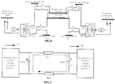
- this embodiment includes two regenerative electric energy feedback devices 1, including two sets of regenerative electric energy feedback devices and switches connected to the devices.
- the two systems have the same configurations.
- a schematic diagram including the two sets of regenerative electric energy feedback devices is shown in FIG. 1 .
- Two adjacent stations are connected via a contact network.
- a direct-current side positive electrode of each regenerative electric energy feedback device is connected to a positive electrode bus of a subway traction network, where the positive electrode bus is connected to an uplink contact network and a downlink contact network respectively via a first switching switch 4 and a second switching switch 5.
- a direct-current side negative electrode of the regenerative electric energy feedback device is connected to the downlink contact network via a third switching switch 2, and the direct-current side negative electrode is connected to a negative electrode bus of the subway traction network via a fourth switching switch 3.
- the regenerative electric energy feedback device 1 includes a rectifier formed by power semiconductor devices.
- the rectifier has a function of enabling active power to flow in two directions, that is, the rectifier can control the active power to flow from an alternating-current power grid to a direct-current bus of the subway traction network, and can also control the active power to flow from the direct-current bus of the subway traction network to the alternating-current power grid.
- a topological structure of the rectifier is shown in FIG. 2 .
- the rectifier has a three-phase bridge rectifier circuit formed by an insulated-gate bipolar transistor (IGBT), which can implement bidirectional flow of the power.
- IGBT insulated-gate bipolar transistor
- the third switching switch 2 and the fourth switching switch 3 are interlocked, and are not allowed to be closed at the same time.
- FIG. 5 is an equivalent schematic diagram in an ice melting status. A specific method for controlling an ice-melting current is described with reference to FIG. 5 .
- the capacitance of the regenerative electric energy feedback device 1 is in a discharge status, and maintains constant at 1800V.
- the regenerative electric energy feedback device 1 needs to acquire the power PI from the alternating-current power grid.
- the capacitance of the regenerative electric energy feedback device 2 is in a charging status.
- the surplus power P2 needs to be delivered back to the power grid.
- An energy difference of P1-P2 is consumed for the resistance of the contact network, thus melting the ice by using the heat.
Landscapes
- Engineering & Computer Science (AREA)
- Mechanical Engineering (AREA)
- Power Engineering (AREA)
- Transportation (AREA)
- Electric Propulsion And Braking For Vehicles (AREA)
- Inverter Devices (AREA)
Claims (5)
- Regeneratives Stromrückspeisungssystem einer Lokomotive mit einer Eisschmelzfunktion, das zwei regenerative Stromrückspeisungsvorrichtungen (1) umfasst, wobei eine gleichstromseitige positive Elektrode jeder regenerativen Stromrückspeisungsvorrichtung (1) mit einer jeweiligen positiven Elektrodensammelschiene eines U-Bahn-Traktionsnetzes verbunden ist, wobei jede positive Elektrodensammelschiene über einen ersten Schaltschalter (4) und einen zweiten Schaltschalter (5) mit einem Uplink-Kontaktnetz bzw. einem Downlink-Kontaktnetz verbunden ist, dadurch gekennzeichnet, dass eine gleichstromseitige negative Elektrode jeder regenerativen Stromrückspeisungsvorrichtung (1) über einen dritten Schaltschalter (2) mit dem Downlink-Kontaktnetz oder dem Uplink-Kontaktnetz verbunden ist, wobei jede gleichstromseitige negative Elektrode über einen vierten Schaltschalter (3) mit einer jeweiligen negativen Elektrodensammelschiene des U-Bahn-Traktionsnetzes verbunden ist.
- Regeneratives Stromrückspeisungssystem einer Lokomotive mit einer Eisschmelzfunktion nach Anspruch 1, dadurch gekennzeichnet, dass jede regenerative Stromrückspeisungsvorrichtung (1) einen Gleichrichter umfasst, der aus Leistungshalbleitervorrichtungen gebildet ist; wobei der Gleichrichter die Funktion hat, die es ermöglicht, dass Wirkleistung in zwei Richtungen fließt, d. h., der Gleichrichter ist in der Lage, den Wirkleistungsfluss von einem Wechselstromnetz zu einer Gleichstromsammelschiene des U-Bahn-Traktionsnetzes zu steuern, und er ist auch in der Lage, den Fluss der Wirkleistung von der Gleichstromsammelschiene des U-Bahn-Traktionsnetzes zu dem Wechselstromnetz zu steuern.
- Stromrückspeisungssystem einer Lokomotive mit einer Eisschmelzfunktion nach Anspruch 1, dadurch gekennzeichnet, dass der dritte Schaltschalter (2) und der vierte Schaltschalter (3) nicht gleichzeitig geschlossen sein dürfen.
- Steuerungsverfahren für das regenerative Stromrückspeisungssystem einer Lokomotive mit einer Eisschmelzfunktion nach Anspruch 1, dadurch gekennzeichnet, dass dann, wenn die regenerativen Stromrückspeisungsvorrichtungen (1) in einem Stromrückspeisungszustand arbeiten, das Steuerungsverfahren die folgenden Schritte umfasst:Schritt 1: Öffnen der dritten Schaltschalter (2);Schritt 2: Schließen der vierten Schaltschalter (3); undSchritt 3: Starten der regenerativen Stromrückspeisungsvorrichtungen (1), wenn die Lokomotive bremst, um den Fluss der Wirkleistung von einer Gleichstromsammelschiene eines U-Bahn-Traktionsnetzes zu einem Wechselstromnetz zu steuern.
- Steuerungsverfahren für das regenerative Stromrückspeisungssystem einer Lokomotive mit einer Eisschmelzfunktion nach Anspruch 1, dadurch gekennzeichnet, dass, wenn die regenerativen Stromrückspeisungsvorrichtungen (1) in einem Eisschmelzzustand arbeiten, das Steuerungsverfahren konkret wie folgt ist:wenn die dritten Schaltschalter (2) mit einem Uplink-Kontaktnetz verbunden sind, sind die Schritte wie folgt:Schritt 101: Öffnen der ersten Schaltschalter (4) und der vierten Schaltschalter (3);Schritt 102: Schließen der zweiten Schaltschalter (5) und der dritten Schaltschalter (2);Schritt 103: Starten eines Gleichrichters einer der regenerativen Stromrückspeisungsvorrichtungen (1), um eine Gleichspannung zu stabilisieren; undSchritt 104: Starten eines Gleichrichters der anderen der regenerativen Stromrückspeisungsvorrichtungen (1), um den durch das Kontaktnetz fließenden Strom zu stabilisieren; oderwenn die dritten Schaltschalter (2) an ein Downlink-Kontaktnetz angeschlossen sind, sind die Schritte wie folgt:Schritt 201: Öffnen der zweiten Schaltschalter (5) und der vierten Schaltschalter (3);Schritt 202: Schließen der ersten Schaltschalter (4) und der dritten Schaltschalter (2);Schritt 203: Starten eines Gleichrichters einer der regenerativen Stromrückspeisungsvorrichtungen (1), um eine Gleichspannung eines Traktionsnetzes zu stabilisieren; undSchritt 204: Starten eines Gleichrichters der anderen regenerativen Stromrückspeisungsvorrichtungen (1), um den durch das Kontaktnetz fließenden Strom zu stabilisieren.
Applications Claiming Priority (2)
| Application Number | Priority Date | Filing Date | Title |
|---|---|---|---|
| CN201610121099.XA CN105730248B (zh) | 2016-03-03 | 2016-03-03 | 一种兼有融冰功能的机车再生电能回馈系统及控制方法 |
| PCT/CN2017/075368 WO2017148397A1 (zh) | 2016-03-03 | 2017-03-01 | 一种兼有融冰功能的机车再生电能回馈系统及控制方法 |
Publications (3)
| Publication Number | Publication Date |
|---|---|
| EP3406476A1 EP3406476A1 (de) | 2018-11-28 |
| EP3406476A4 EP3406476A4 (de) | 2019-10-02 |
| EP3406476B1 true EP3406476B1 (de) | 2021-10-20 |
Family
ID=56249122
Family Applications (1)
| Application Number | Title | Priority Date | Filing Date |
|---|---|---|---|
| EP17759248.2A Active EP3406476B1 (de) | 2016-03-03 | 2017-03-01 | Regeneratives stromfeedbacksystem einer lokomotive mit eisschmelzfunktion und steuerungsverfahren |
Country Status (8)
| Country | Link |
|---|---|
| US (1) | US10279686B2 (de) |
| EP (1) | EP3406476B1 (de) |
| JP (1) | JP6571294B2 (de) |
| KR (1) | KR101975159B1 (de) |
| CN (1) | CN105730248B (de) |
| CA (1) | CA3015421C (de) |
| RU (1) | RU2686605C1 (de) |
| WO (1) | WO2017148397A1 (de) |
Families Citing this family (20)
| Publication number | Priority date | Publication date | Assignee | Title |
|---|---|---|---|---|
| CN105730248B (zh) | 2016-03-03 | 2017-10-13 | 南京南瑞继保电气有限公司 | 一种兼有融冰功能的机车再生电能回馈系统及控制方法 |
| EP3693207A1 (de) * | 2019-02-11 | 2020-08-12 | Lef Holding S.r.l. | System zur heizung von oberleitungen elektrifizierter eisenbahnstrecken |
| CN110481388B (zh) * | 2019-07-17 | 2022-11-22 | 中车永济电机有限公司 | 大功率永磁直驱机车牵引系统自动过分相控制方法 |
| CN111525656B (zh) * | 2020-06-03 | 2022-03-18 | 桑顿新能源科技(长沙)有限公司 | 电池电能回馈系统以及车辆 |
| CN112054465B (zh) * | 2020-07-22 | 2022-01-21 | 广东顺德电力设计院有限公司 | 一种opgw融冰系统 |
| CN112260198B (zh) * | 2020-09-28 | 2024-09-27 | 北京交通大学 | 一种多功能的轨道交通直流在线融冰系统及方法 |
| CN113131536B (zh) * | 2021-04-21 | 2022-07-08 | 重庆中车长客轨道车辆有限公司 | 用于双流制测试线的联锁控制系统 |
| CN113131537B (zh) * | 2021-04-21 | 2022-07-08 | 重庆中车长客轨道车辆有限公司 | 双流制测试线用联锁控制方法 |
| US11654781B2 (en) | 2021-05-24 | 2023-05-23 | Mark Ogram | Locomotive assist |
| CN113370849B (zh) * | 2021-07-30 | 2022-12-02 | 清华大学 | 兼具融冰与能馈功能的牵引供电系统 |
| CN116093866A (zh) * | 2021-11-08 | 2023-05-09 | 株洲中车时代电气股份有限公司 | 接触网融冰系统及方法 |
| CN114336584A (zh) * | 2021-12-23 | 2022-04-12 | 核工业理化工程研究院 | 一种用于地铁再生能量吸收利用的控制系统及其控制方法 |
| CN114530814B (zh) * | 2022-04-15 | 2022-09-30 | 西南交通大学 | 一种电气化铁路接触网直流融冰系统及其控制方法 |
| CN114825237B (zh) * | 2022-05-17 | 2024-01-16 | 深圳量云能源网络科技有限公司 | 基于轨道交通系统的接触网防冰及融冰控制方法及系统 |
| CN115296246B (zh) * | 2022-08-26 | 2024-05-28 | 中国南方电网有限责任公司超高压输电公司检修试验中心 | 高压直流不停电地线融冰电路、设备及操作方法 |
| CN115642552B (zh) * | 2022-10-10 | 2024-04-30 | 中铁第一勘察设计院集团有限公司 | 一种城市轨道交通接触网直流在线防融冰系统 |
| CN115684789A (zh) * | 2022-10-28 | 2023-02-03 | 南京南瑞继保工程技术有限公司 | 一种兼有融冰功能的机车再生电能回馈系统的试验方法 |
| PL248867B1 (pl) * | 2023-03-02 | 2026-02-09 | Pkp Energetyka Spolka Akcyjna | Układ energoelektroniczny do zasilania systemu odladzania sieci trakcyjnej prądu stałego |
| CN120638430B (zh) * | 2025-08-13 | 2025-12-26 | 合肥召洋电子科技有限公司 | 兼具直流融冰功能的地铁飞轮储能系统及融冰储能方法 |
| CN120638217B (zh) * | 2025-08-13 | 2025-11-07 | 江苏同芯电气科技有限公司 | 一种兼具直流融冰功能的地铁能馈系统及融冰能馈方法 |
Family Cites Families (20)
| Publication number | Priority date | Publication date | Assignee | Title |
|---|---|---|---|---|
| SU1227530A1 (ru) * | 1984-01-13 | 1986-04-30 | Kryukov Leonid P | Устройство подогрева контактной подвески |
| JPH0491659A (ja) * | 1990-08-06 | 1992-03-25 | Tokyo Electric Power Co Inc:The | 電力変換装置 |
| DE19757079A1 (de) * | 1996-12-23 | 1998-06-25 | Rostislaw Teteruk | Eissensorsystem |
| JP2004358984A (ja) * | 2003-06-02 | 2004-12-24 | Railway Technical Res Inst | 電鉄用直流電力供給設備 |
| DE10337937B4 (de) * | 2003-08-18 | 2006-03-09 | Siemens Ag | Verfahren und Anordnung zum Verhindern oder Beseitigen einer Vereisung am Fahrdraht einer Eisenbahnstrecke |
| CN1929287A (zh) * | 2005-09-07 | 2007-03-14 | 上海神源电气有限公司 | 能将电能回馈给电网的装置 |
| CN201113916Y (zh) * | 2007-10-25 | 2008-09-10 | 北京剑能电气有限公司 | 多台变频器共用制动单元节能装置 |
| JP2009248615A (ja) * | 2008-04-02 | 2009-10-29 | Meidensha Corp | 回生電力吸収装置 |
| US20090250449A1 (en) * | 2008-04-02 | 2009-10-08 | The Trustees Of Dartmouth College | System And Method For Deicing Of Power Line Cables |
| JP5458613B2 (ja) * | 2009-03-16 | 2014-04-02 | 株式会社明電舎 | 回生対策装置と回生対策装置の制御方法 |
| CN101640400A (zh) * | 2009-07-23 | 2010-02-03 | 中铁第一勘察设计院集团有限公司 | 一种电气化铁路接触网的融冰方法及其融冰系统 |
| FR2958887B1 (fr) * | 2010-04-19 | 2015-07-03 | Alstom Transport Sa | Procede de degivrage d'une ligne d'alimentation de vehicules ferroviaires |
| WO2012034124A2 (en) * | 2010-09-10 | 2012-03-15 | The Trustees Of Dartmouth College | System and method for deicing of power line cables |
| CN201980097U (zh) * | 2011-02-18 | 2011-09-21 | 株洲变流技术国家工程研究中心有限公司 | 用于铁路牵引网的功率调节-融冰装置 |
| JP5264949B2 (ja) * | 2011-03-08 | 2013-08-14 | 本田技研工業株式会社 | 電動車両 |
| CN202593308U (zh) * | 2012-04-19 | 2012-12-12 | 南车株洲电力机车有限公司 | 一种用于双电能机车的蓄电池控制电路 |
| CN102832582B (zh) * | 2012-09-12 | 2015-03-25 | 西南交通大学 | 一种交流电气化铁路接触网在线防冰与融冰控制系统 |
| CN104201719B (zh) * | 2014-09-09 | 2017-03-29 | 南京南瑞继保电气有限公司 | 一种机车再生电能回馈设备及控制方法 |
| CN105034854B (zh) * | 2015-07-13 | 2017-06-13 | 中电博瑞技术(北京)有限公司 | 融冰装置 |
| CN105730248B (zh) * | 2016-03-03 | 2017-10-13 | 南京南瑞继保电气有限公司 | 一种兼有融冰功能的机车再生电能回馈系统及控制方法 |
-
2016
- 2016-03-03 CN CN201610121099.XA patent/CN105730248B/zh active Active
-
2017
- 2017-03-01 KR KR1020187024836A patent/KR101975159B1/ko active Active
- 2017-03-01 CA CA3015421A patent/CA3015421C/en active Active
- 2017-03-01 RU RU2018132820A patent/RU2686605C1/ru active
- 2017-03-01 JP JP2018544212A patent/JP6571294B2/ja active Active
- 2017-03-01 US US16/080,276 patent/US10279686B2/en active Active
- 2017-03-01 EP EP17759248.2A patent/EP3406476B1/de active Active
- 2017-03-01 WO PCT/CN2017/075368 patent/WO2017148397A1/zh not_active Ceased
Also Published As
| Publication number | Publication date |
|---|---|
| JP6571294B2 (ja) | 2019-09-04 |
| EP3406476A1 (de) | 2018-11-28 |
| CA3015421A1 (en) | 2017-09-08 |
| KR20180100707A (ko) | 2018-09-11 |
| CN105730248B (zh) | 2017-10-13 |
| KR101975159B1 (ko) | 2019-05-03 |
| EP3406476A4 (de) | 2019-10-02 |
| RU2686605C1 (ru) | 2019-04-29 |
| US20190070964A1 (en) | 2019-03-07 |
| US10279686B2 (en) | 2019-05-07 |
| CA3015421C (en) | 2019-05-14 |
| JP2019509209A (ja) | 2019-04-04 |
| CN105730248A (zh) | 2016-07-06 |
| WO2017148397A1 (zh) | 2017-09-08 |
Similar Documents
| Publication | Publication Date | Title |
|---|---|---|
| CA3015421C (en) | Locomotive regenerative electric energy feedback system with ice melting function and control method | |
| KR101715444B1 (ko) | 축전 장치와 그 설치 및 운용 방법 | |
| AU2021347695B2 (en) | Lithium battery system and overhead working truck | |
| CN109823187B (zh) | 一种电制动能量回馈系统 | |
| CN112260198A (zh) | 一种多功能的轨道交通直流在线融冰系统及方法 | |
| RS59186B1 (sr) | Sistem, podstanica i postupak za rekuperaciju energije kočenja kod šinskih vozila, šinska vozila za ovaj sistem | |
| CN112260342B (zh) | 锂电池系统及高空作业车 | |
| CN113608571A (zh) | 一种光伏发电单元的灵活功率跟踪控制方法及其应用 | |
| CN112260199A (zh) | 轨道交通交流在线融冰系统及方法 | |
| CN105034854B (zh) | 融冰装置 | |
| CN112152270A (zh) | 应用于地铁列车再生制动的超导磁储能装置及其控制方法 | |
| CN114530814B (zh) | 一种电气化铁路接触网直流融冰系统及其控制方法 | |
| CN106100000A (zh) | 变流装置、城轨牵引供电系统及其控制方法 | |
| CN213879227U (zh) | 一种多功能的轨道交通直流在线融冰系统 | |
| CN205407265U (zh) | 一种贯通供电系统变流器型牵引变电所潮流调控装置 | |
| KR20160020623A (ko) | 전차선 해빙 시스템 및 이를 이용한 해빙 방법 | |
| CN110137893A (zh) | 一种全桥mmc型融冰试验装置和方法 | |
| Lukasiak et al. | Technology comparison of energy recuperation systems for DC rail transportation | |
| CN209938340U (zh) | 一种轨道车辆动力电源混合供电系统 | |
| CN223713426U (zh) | 一种基于斩波电路智能控制的移动式储能融冰装置及移动车体 | |
| Takahashi et al. | Energy storage for traction power supply systems | |
| CN106696979B (zh) | 铁路棚车用供电系统及铁路棚车 | |
| CN206327379U (zh) | 铁路棚车用供电系统及铁路棚车 | |
| CN204615406U (zh) | 能量回馈变压器设备 | |
| KR100483807B1 (ko) | 회생용 3레벨 피더블유엠 컨버터를 이용한 전동차직류전원 공급 시스템 |
Legal Events
| Date | Code | Title | Description |
|---|---|---|---|
| STAA | Information on the status of an ep patent application or granted ep patent |
Free format text: STATUS: THE INTERNATIONAL PUBLICATION HAS BEEN MADE |
|
| PUAI | Public reference made under article 153(3) epc to a published international application that has entered the european phase |
Free format text: ORIGINAL CODE: 0009012 |
|
| STAA | Information on the status of an ep patent application or granted ep patent |
Free format text: STATUS: REQUEST FOR EXAMINATION WAS MADE |
|
| 17P | Request for examination filed |
Effective date: 20180822 |
|
| AK | Designated contracting states |
Kind code of ref document: A1 Designated state(s): AL AT BE BG CH CY CZ DE DK EE ES FI FR GB GR HR HU IE IS IT LI LT LU LV MC MK MT NL NO PL PT RO RS SE SI SK SM TR |
|
| AX | Request for extension of the european patent |
Extension state: BA ME |
|
| DAV | Request for validation of the european patent (deleted) | ||
| DAX | Request for extension of the european patent (deleted) | ||
| REG | Reference to a national code |
Ref country code: DE Ref legal event code: R079 Ref document number: 602017047928 Country of ref document: DE Free format text: PREVIOUS MAIN CLASS: B60L0007100000 Ipc: B60M0003060000 |
|
| A4 | Supplementary search report drawn up and despatched |
Effective date: 20190902 |
|
| RIC1 | Information provided on ipc code assigned before grant |
Ipc: H02G 7/16 20060101ALI20190827BHEP Ipc: B60M 1/12 20060101ALI20190827BHEP Ipc: B60M 3/06 20060101AFI20190827BHEP |
|
| GRAP | Despatch of communication of intention to grant a patent |
Free format text: ORIGINAL CODE: EPIDOSNIGR1 |
|
| STAA | Information on the status of an ep patent application or granted ep patent |
Free format text: STATUS: GRANT OF PATENT IS INTENDED |
|
| INTG | Intention to grant announced |
Effective date: 20210519 |
|
| GRAS | Grant fee paid |
Free format text: ORIGINAL CODE: EPIDOSNIGR3 |
|
| GRAA | (expected) grant |
Free format text: ORIGINAL CODE: 0009210 |
|
| STAA | Information on the status of an ep patent application or granted ep patent |
Free format text: STATUS: THE PATENT HAS BEEN GRANTED |
|
| AK | Designated contracting states |
Kind code of ref document: B1 Designated state(s): AL AT BE BG CH CY CZ DE DK EE ES FI FR GB GR HR HU IE IS IT LI LT LU LV MC MK MT NL NO PL PT RO RS SE SI SK SM TR |
|
| REG | Reference to a national code |
Ref country code: GB Ref legal event code: FG4D |
|
| REG | Reference to a national code |
Ref country code: CH Ref legal event code: EP |
|
| REG | Reference to a national code |
Ref country code: IE Ref legal event code: FG4D |
|
| REG | Reference to a national code |
Ref country code: DE Ref legal event code: R096 Ref document number: 602017047928 Country of ref document: DE |
|
| REG | Reference to a national code |
Ref country code: AT Ref legal event code: REF Ref document number: 1439672 Country of ref document: AT Kind code of ref document: T Effective date: 20211115 |
|
| REG | Reference to a national code |
Ref country code: LT Ref legal event code: MG9D |
|
| REG | Reference to a national code |
Ref country code: NL Ref legal event code: MP Effective date: 20211020 |
|
| REG | Reference to a national code |
Ref country code: AT Ref legal event code: MK05 Ref document number: 1439672 Country of ref document: AT Kind code of ref document: T Effective date: 20211020 |
|
| PG25 | Lapsed in a contracting state [announced via postgrant information from national office to epo] |
Ref country code: RS Free format text: LAPSE BECAUSE OF FAILURE TO SUBMIT A TRANSLATION OF THE DESCRIPTION OR TO PAY THE FEE WITHIN THE PRESCRIBED TIME-LIMIT Effective date: 20211020 Ref country code: LT Free format text: LAPSE BECAUSE OF FAILURE TO SUBMIT A TRANSLATION OF THE DESCRIPTION OR TO PAY THE FEE WITHIN THE PRESCRIBED TIME-LIMIT Effective date: 20211020 Ref country code: FI Free format text: LAPSE BECAUSE OF FAILURE TO SUBMIT A TRANSLATION OF THE DESCRIPTION OR TO PAY THE FEE WITHIN THE PRESCRIBED TIME-LIMIT Effective date: 20211020 Ref country code: BG Free format text: LAPSE BECAUSE OF FAILURE TO SUBMIT A TRANSLATION OF THE DESCRIPTION OR TO PAY THE FEE WITHIN THE PRESCRIBED TIME-LIMIT Effective date: 20220120 Ref country code: AT Free format text: LAPSE BECAUSE OF FAILURE TO SUBMIT A TRANSLATION OF THE DESCRIPTION OR TO PAY THE FEE WITHIN THE PRESCRIBED TIME-LIMIT Effective date: 20211020 |
|
| PG25 | Lapsed in a contracting state [announced via postgrant information from national office to epo] |
Ref country code: IS Free format text: LAPSE BECAUSE OF FAILURE TO SUBMIT A TRANSLATION OF THE DESCRIPTION OR TO PAY THE FEE WITHIN THE PRESCRIBED TIME-LIMIT Effective date: 20220220 Ref country code: SE Free format text: LAPSE BECAUSE OF FAILURE TO SUBMIT A TRANSLATION OF THE DESCRIPTION OR TO PAY THE FEE WITHIN THE PRESCRIBED TIME-LIMIT Effective date: 20211020 Ref country code: PT Free format text: LAPSE BECAUSE OF FAILURE TO SUBMIT A TRANSLATION OF THE DESCRIPTION OR TO PAY THE FEE WITHIN THE PRESCRIBED TIME-LIMIT Effective date: 20220221 Ref country code: PL Free format text: LAPSE BECAUSE OF FAILURE TO SUBMIT A TRANSLATION OF THE DESCRIPTION OR TO PAY THE FEE WITHIN THE PRESCRIBED TIME-LIMIT Effective date: 20211020 Ref country code: NO Free format text: LAPSE BECAUSE OF FAILURE TO SUBMIT A TRANSLATION OF THE DESCRIPTION OR TO PAY THE FEE WITHIN THE PRESCRIBED TIME-LIMIT Effective date: 20220120 Ref country code: NL Free format text: LAPSE BECAUSE OF FAILURE TO SUBMIT A TRANSLATION OF THE DESCRIPTION OR TO PAY THE FEE WITHIN THE PRESCRIBED TIME-LIMIT Effective date: 20211020 Ref country code: LV Free format text: LAPSE BECAUSE OF FAILURE TO SUBMIT A TRANSLATION OF THE DESCRIPTION OR TO PAY THE FEE WITHIN THE PRESCRIBED TIME-LIMIT Effective date: 20211020 Ref country code: HR Free format text: LAPSE BECAUSE OF FAILURE TO SUBMIT A TRANSLATION OF THE DESCRIPTION OR TO PAY THE FEE WITHIN THE PRESCRIBED TIME-LIMIT Effective date: 20211020 Ref country code: GR Free format text: LAPSE BECAUSE OF FAILURE TO SUBMIT A TRANSLATION OF THE DESCRIPTION OR TO PAY THE FEE WITHIN THE PRESCRIBED TIME-LIMIT Effective date: 20220121 Ref country code: ES Free format text: LAPSE BECAUSE OF FAILURE TO SUBMIT A TRANSLATION OF THE DESCRIPTION OR TO PAY THE FEE WITHIN THE PRESCRIBED TIME-LIMIT Effective date: 20211020 |
|
| REG | Reference to a national code |
Ref country code: DE Ref legal event code: R097 Ref document number: 602017047928 Country of ref document: DE |
|
| PG25 | Lapsed in a contracting state [announced via postgrant information from national office to epo] |
Ref country code: SM Free format text: LAPSE BECAUSE OF FAILURE TO SUBMIT A TRANSLATION OF THE DESCRIPTION OR TO PAY THE FEE WITHIN THE PRESCRIBED TIME-LIMIT Effective date: 20211020 Ref country code: SK Free format text: LAPSE BECAUSE OF FAILURE TO SUBMIT A TRANSLATION OF THE DESCRIPTION OR TO PAY THE FEE WITHIN THE PRESCRIBED TIME-LIMIT Effective date: 20211020 Ref country code: RO Free format text: LAPSE BECAUSE OF FAILURE TO SUBMIT A TRANSLATION OF THE DESCRIPTION OR TO PAY THE FEE WITHIN THE PRESCRIBED TIME-LIMIT Effective date: 20211020 Ref country code: EE Free format text: LAPSE BECAUSE OF FAILURE TO SUBMIT A TRANSLATION OF THE DESCRIPTION OR TO PAY THE FEE WITHIN THE PRESCRIBED TIME-LIMIT Effective date: 20211020 Ref country code: DK Free format text: LAPSE BECAUSE OF FAILURE TO SUBMIT A TRANSLATION OF THE DESCRIPTION OR TO PAY THE FEE WITHIN THE PRESCRIBED TIME-LIMIT Effective date: 20211020 Ref country code: CZ Free format text: LAPSE BECAUSE OF FAILURE TO SUBMIT A TRANSLATION OF THE DESCRIPTION OR TO PAY THE FEE WITHIN THE PRESCRIBED TIME-LIMIT Effective date: 20211020 |
|
| PLBE | No opposition filed within time limit |
Free format text: ORIGINAL CODE: 0009261 |
|
| STAA | Information on the status of an ep patent application or granted ep patent |
Free format text: STATUS: NO OPPOSITION FILED WITHIN TIME LIMIT |
|
| 26N | No opposition filed |
Effective date: 20220721 |
|
| PG25 | Lapsed in a contracting state [announced via postgrant information from national office to epo] |
Ref country code: MC Free format text: LAPSE BECAUSE OF FAILURE TO SUBMIT A TRANSLATION OF THE DESCRIPTION OR TO PAY THE FEE WITHIN THE PRESCRIBED TIME-LIMIT Effective date: 20211020 Ref country code: AL Free format text: LAPSE BECAUSE OF FAILURE TO SUBMIT A TRANSLATION OF THE DESCRIPTION OR TO PAY THE FEE WITHIN THE PRESCRIBED TIME-LIMIT Effective date: 20211020 |
|
| REG | Reference to a national code |
Ref country code: CH Ref legal event code: PL |
|
| GBPC | Gb: european patent ceased through non-payment of renewal fee |
Effective date: 20220301 |
|
| PG25 | Lapsed in a contracting state [announced via postgrant information from national office to epo] |
Ref country code: SI Free format text: LAPSE BECAUSE OF FAILURE TO SUBMIT A TRANSLATION OF THE DESCRIPTION OR TO PAY THE FEE WITHIN THE PRESCRIBED TIME-LIMIT Effective date: 20211020 |
|
| REG | Reference to a national code |
Ref country code: BE Ref legal event code: MM Effective date: 20220331 |
|
| PG25 | Lapsed in a contracting state [announced via postgrant information from national office to epo] |
Ref country code: LU Free format text: LAPSE BECAUSE OF NON-PAYMENT OF DUE FEES Effective date: 20220301 Ref country code: LI Free format text: LAPSE BECAUSE OF NON-PAYMENT OF DUE FEES Effective date: 20220331 Ref country code: IE Free format text: LAPSE BECAUSE OF NON-PAYMENT OF DUE FEES Effective date: 20220301 Ref country code: GB Free format text: LAPSE BECAUSE OF NON-PAYMENT OF DUE FEES Effective date: 20220301 Ref country code: CH Free format text: LAPSE BECAUSE OF NON-PAYMENT OF DUE FEES Effective date: 20220331 |
|
| PG25 | Lapsed in a contracting state [announced via postgrant information from national office to epo] |
Ref country code: BE Free format text: LAPSE BECAUSE OF NON-PAYMENT OF DUE FEES Effective date: 20220331 |
|
| PG25 | Lapsed in a contracting state [announced via postgrant information from national office to epo] |
Ref country code: HU Free format text: LAPSE BECAUSE OF FAILURE TO SUBMIT A TRANSLATION OF THE DESCRIPTION OR TO PAY THE FEE WITHIN THE PRESCRIBED TIME-LIMIT; INVALID AB INITIO Effective date: 20170301 |
|
| PG25 | Lapsed in a contracting state [announced via postgrant information from national office to epo] |
Ref country code: MK Free format text: LAPSE BECAUSE OF FAILURE TO SUBMIT A TRANSLATION OF THE DESCRIPTION OR TO PAY THE FEE WITHIN THE PRESCRIBED TIME-LIMIT Effective date: 20211020 Ref country code: CY Free format text: LAPSE BECAUSE OF FAILURE TO SUBMIT A TRANSLATION OF THE DESCRIPTION OR TO PAY THE FEE WITHIN THE PRESCRIBED TIME-LIMIT Effective date: 20211020 |
|
| PG25 | Lapsed in a contracting state [announced via postgrant information from national office to epo] |
Ref country code: MT Free format text: LAPSE BECAUSE OF FAILURE TO SUBMIT A TRANSLATION OF THE DESCRIPTION OR TO PAY THE FEE WITHIN THE PRESCRIBED TIME-LIMIT Effective date: 20211020 |
|
| PG25 | Lapsed in a contracting state [announced via postgrant information from national office to epo] |
Ref country code: TR Free format text: LAPSE BECAUSE OF FAILURE TO SUBMIT A TRANSLATION OF THE DESCRIPTION OR TO PAY THE FEE WITHIN THE PRESCRIBED TIME-LIMIT Effective date: 20211020 |
|
| PGFP | Annual fee paid to national office [announced via postgrant information from national office to epo] |
Ref country code: DE Payment date: 20260313 Year of fee payment: 10 |
|
| PGFP | Annual fee paid to national office [announced via postgrant information from national office to epo] |
Ref country code: IT Payment date: 20260309 Year of fee payment: 10 |
|
| PGFP | Annual fee paid to national office [announced via postgrant information from national office to epo] |
Ref country code: FR Payment date: 20260330 Year of fee payment: 10 |