EP3406231A1 - Wound dressing and method of treatment - Google Patents
Wound dressing and method of treatment Download PDFInfo
- Publication number
- EP3406231A1 EP3406231A1 EP18171902.2A EP18171902A EP3406231A1 EP 3406231 A1 EP3406231 A1 EP 3406231A1 EP 18171902 A EP18171902 A EP 18171902A EP 3406231 A1 EP3406231 A1 EP 3406231A1
- Authority
- EP
- European Patent Office
- Prior art keywords
- layer
- wound
- dressing
- obscuring
- absorbent
- Prior art date
- Legal status (The legal status is an assumption and is not a legal conclusion. Google has not performed a legal analysis and makes no representation as to the accuracy of the status listed.)
- Granted
Links
- 238000000034 method Methods 0.000 title abstract description 36
- 206010052428 Wound Diseases 0.000 claims abstract description 489
- 208000027418 Wounds and injury Diseases 0.000 claims abstract description 489
- 239000002250 absorbent Substances 0.000 claims description 228
- 230000002745 absorbent Effects 0.000 claims description 225
- 239000007788 liquid Substances 0.000 claims description 27
- 239000000853 adhesive Substances 0.000 claims description 24
- 230000001070 adhesive effect Effects 0.000 claims description 24
- 230000000699 topical effect Effects 0.000 claims description 15
- 229920003043 Cellulose fiber Polymers 0.000 claims description 13
- 239000002245 particle Substances 0.000 claims description 13
- 230000002209 hydrophobic effect Effects 0.000 claims description 11
- 239000007789 gas Substances 0.000 claims description 9
- 239000012530 fluid Substances 0.000 abstract description 73
- 238000012544 monitoring process Methods 0.000 abstract description 3
- 239000010410 layer Substances 0.000 description 705
- 239000000463 material Substances 0.000 description 138
- 210000000416 exudates and transudate Anatomy 0.000 description 62
- 230000005540 biological transmission Effects 0.000 description 38
- 239000004744 fabric Substances 0.000 description 33
- 230000000873 masking effect Effects 0.000 description 29
- 125000006850 spacer group Chemical group 0.000 description 29
- 239000003570 air Substances 0.000 description 21
- 238000009826 distribution Methods 0.000 description 21
- 238000012360 testing method Methods 0.000 description 13
- 230000000007 visual effect Effects 0.000 description 13
- 239000004820 Pressure-sensitive adhesive Substances 0.000 description 12
- 239000012790 adhesive layer Substances 0.000 description 12
- 238000010586 diagram Methods 0.000 description 11
- 239000010408 film Substances 0.000 description 10
- 229920006264 polyurethane film Polymers 0.000 description 10
- 210000001519 tissue Anatomy 0.000 description 10
- 244000027321 Lychnis chalcedonica Species 0.000 description 9
- 230000008859 change Effects 0.000 description 9
- 238000009581 negative-pressure wound therapy Methods 0.000 description 9
- OKTJSMMVPCPJKN-UHFFFAOYSA-N Carbon Chemical compound [C] OKTJSMMVPCPJKN-UHFFFAOYSA-N 0.000 description 8
- 150000001875 compounds Chemical class 0.000 description 8
- 229920000728 polyester Polymers 0.000 description 8
- -1 polypropylene Polymers 0.000 description 8
- 238000007789 sealing Methods 0.000 description 8
- 230000004888 barrier function Effects 0.000 description 7
- 229920002678 cellulose Polymers 0.000 description 7
- 239000001913 cellulose Substances 0.000 description 7
- 238000004891 communication Methods 0.000 description 7
- 239000000835 fiber Substances 0.000 description 7
- NIXOWILDQLNWCW-UHFFFAOYSA-N acrylic acid group Chemical group C(C=C)(=O)O NIXOWILDQLNWCW-UHFFFAOYSA-N 0.000 description 6
- 230000001580 bacterial effect Effects 0.000 description 6
- 239000003086 colorant Substances 0.000 description 6
- 239000011148 porous material Substances 0.000 description 6
- 230000008569 process Effects 0.000 description 6
- 230000005855 radiation Effects 0.000 description 6
- 230000009467 reduction Effects 0.000 description 6
- 230000001225 therapeutic effect Effects 0.000 description 6
- 238000012546 transfer Methods 0.000 description 6
- 238000012800 visualization Methods 0.000 description 6
- FAPWRFPIFSIZLT-UHFFFAOYSA-M Sodium chloride Chemical compound [Na+].[Cl-] FAPWRFPIFSIZLT-UHFFFAOYSA-M 0.000 description 5
- 238000010521 absorption reaction Methods 0.000 description 5
- 230000006870 function Effects 0.000 description 5
- 229920001296 polysiloxane Polymers 0.000 description 5
- 229920006395 saturated elastomer Polymers 0.000 description 5
- 239000004698 Polyethylene Substances 0.000 description 4
- 239000004743 Polypropylene Substances 0.000 description 4
- 210000004369 blood Anatomy 0.000 description 4
- 239000008280 blood Substances 0.000 description 4
- 239000006260 foam Substances 0.000 description 4
- 230000035876 healing Effects 0.000 description 4
- 230000031700 light absorption Effects 0.000 description 4
- 150000002632 lipids Chemical class 0.000 description 4
- 239000011159 matrix material Substances 0.000 description 4
- 235000019645 odor Nutrition 0.000 description 4
- 229920000573 polyethylene Polymers 0.000 description 4
- 229920001155 polypropylene Polymers 0.000 description 4
- 239000011780 sodium chloride Substances 0.000 description 4
- 238000002560 therapeutic procedure Methods 0.000 description 4
- 208000004210 Pressure Ulcer Diseases 0.000 description 3
- 229920000297 Rayon Polymers 0.000 description 3
- 239000012080 ambient air Substances 0.000 description 3
- 230000008901 benefit Effects 0.000 description 3
- 239000002131 composite material Substances 0.000 description 3
- 238000010276 construction Methods 0.000 description 3
- 238000011109 contamination Methods 0.000 description 3
- 238000013461 design Methods 0.000 description 3
- 230000036074 healthy skin Effects 0.000 description 3
- 208000014674 injury Diseases 0.000 description 3
- 238000007689 inspection Methods 0.000 description 3
- 239000004745 nonwoven fabric Substances 0.000 description 3
- 229920002635 polyurethane Polymers 0.000 description 3
- 239000004814 polyurethane Substances 0.000 description 3
- 230000008733 trauma Effects 0.000 description 3
- 238000003466 welding Methods 0.000 description 3
- 208000034656 Contusions Diseases 0.000 description 2
- 229920001651 Cyanoacrylate Polymers 0.000 description 2
- 229920006347 Elastollan Polymers 0.000 description 2
- 239000004593 Epoxy Substances 0.000 description 2
- 239000004831 Hot glue Substances 0.000 description 2
- MWCLLHOVUTZFKS-UHFFFAOYSA-N Methyl cyanoacrylate Chemical compound COC(=O)C(=C)C#N MWCLLHOVUTZFKS-UHFFFAOYSA-N 0.000 description 2
- 230000009471 action Effects 0.000 description 2
- 230000000903 blocking effect Effects 0.000 description 2
- 239000006227 byproduct Substances 0.000 description 2
- 239000011248 coating agent Substances 0.000 description 2
- 238000000576 coating method Methods 0.000 description 2
- 230000009519 contusion Effects 0.000 description 2
- 230000036541 health Effects 0.000 description 2
- 239000012943 hotmelt Substances 0.000 description 2
- 239000000416 hydrocolloid Substances 0.000 description 2
- 210000003127 knee Anatomy 0.000 description 2
- 210000002414 leg Anatomy 0.000 description 2
- 238000004519 manufacturing process Methods 0.000 description 2
- 239000012528 membrane Substances 0.000 description 2
- 238000012856 packing Methods 0.000 description 2
- 230000035699 permeability Effects 0.000 description 2
- 229920000642 polymer Polymers 0.000 description 2
- 239000004810 polytetrafluoroethylene Substances 0.000 description 2
- 229920001343 polytetrafluoroethylene Polymers 0.000 description 2
- 230000008092 positive effect Effects 0.000 description 2
- 238000002834 transmittance Methods 0.000 description 2
- 241000284156 Clerodendrum quadriloculare Species 0.000 description 1
- 206010056340 Diabetic ulcer Diseases 0.000 description 1
- IAYPIBMASNFSPL-UHFFFAOYSA-N Ethylene oxide Chemical compound C1CO1 IAYPIBMASNFSPL-UHFFFAOYSA-N 0.000 description 1
- 208000035874 Excoriation Diseases 0.000 description 1
- 208000034693 Laceration Diseases 0.000 description 1
- 206010030113 Oedema Diseases 0.000 description 1
- 208000002847 Surgical Wound Diseases 0.000 description 1
- 208000000558 Varicose Ulcer Diseases 0.000 description 1
- 230000003187 abdominal effect Effects 0.000 description 1
- 238000005299 abrasion Methods 0.000 description 1
- 239000006096 absorbing agent Substances 0.000 description 1
- 230000004913 activation Effects 0.000 description 1
- 230000001154 acute effect Effects 0.000 description 1
- 239000000654 additive Substances 0.000 description 1
- 230000000996 additive effect Effects 0.000 description 1
- 230000002411 adverse Effects 0.000 description 1
- 238000005054 agglomeration Methods 0.000 description 1
- 230000002776 aggregation Effects 0.000 description 1
- 238000004458 analytical method Methods 0.000 description 1
- 230000000843 anti-fungal effect Effects 0.000 description 1
- 230000003110 anti-inflammatory effect Effects 0.000 description 1
- 230000000845 anti-microbial effect Effects 0.000 description 1
- 229940121375 antifungal agent Drugs 0.000 description 1
- 230000009286 beneficial effect Effects 0.000 description 1
- 230000015572 biosynthetic process Effects 0.000 description 1
- 230000017531 blood circulation Effects 0.000 description 1
- 229910052799 carbon Inorganic materials 0.000 description 1
- 230000001684 chronic effect Effects 0.000 description 1
- 235000019646 color tone Nutrition 0.000 description 1
- 238000004040 coloring Methods 0.000 description 1
- 238000004590 computer program Methods 0.000 description 1
- 239000002537 cosmetic Substances 0.000 description 1
- 239000013039 cover film Substances 0.000 description 1
- 229910003460 diamond Inorganic materials 0.000 description 1
- 239000010432 diamond Substances 0.000 description 1
- 238000004043 dyeing Methods 0.000 description 1
- 230000000694 effects Effects 0.000 description 1
- 238000010894 electron beam technology Methods 0.000 description 1
- 238000005516 engineering process Methods 0.000 description 1
- 230000008020 evaporation Effects 0.000 description 1
- 238000001704 evaporation Methods 0.000 description 1
- 230000001747 exhibiting effect Effects 0.000 description 1
- 239000002657 fibrous material Substances 0.000 description 1
- 210000002683 foot Anatomy 0.000 description 1
- 230000006872 improvement Effects 0.000 description 1
- 239000012678 infectious agent Substances 0.000 description 1
- 208000015181 infectious disease Diseases 0.000 description 1
- 238000000608 laser ablation Methods 0.000 description 1
- 230000014759 maintenance of location Effects 0.000 description 1
- 230000007246 mechanism Effects 0.000 description 1
- 238000012986 modification Methods 0.000 description 1
- 230000004048 modification Effects 0.000 description 1
- 230000009965 odorless effect Effects 0.000 description 1
- 244000052769 pathogen Species 0.000 description 1
- 230000037361 pathway Effects 0.000 description 1
- 229920001495 poly(sodium acrylate) polymer Polymers 0.000 description 1
- 229920006254 polymer film Polymers 0.000 description 1
- 229920000915 polyvinyl chloride Polymers 0.000 description 1
- 239000004800 polyvinyl chloride Substances 0.000 description 1
- 238000011176 pooling Methods 0.000 description 1
- 239000000843 powder Substances 0.000 description 1
- 238000007639 printing Methods 0.000 description 1
- 239000000047 product Substances 0.000 description 1
- 210000000954 sacrococcygeal region Anatomy 0.000 description 1
- 238000009738 saturating Methods 0.000 description 1
- NNMHYFLPFNGQFZ-UHFFFAOYSA-M sodium polyacrylate Chemical compound [Na+].[O-]C(=O)C=C NNMHYFLPFNGQFZ-UHFFFAOYSA-M 0.000 description 1
- 241000894007 species Species 0.000 description 1
- 230000001954 sterilising effect Effects 0.000 description 1
- 238000004659 sterilization and disinfection Methods 0.000 description 1
- 239000000126 substance Substances 0.000 description 1
- 238000006467 substitution reaction Methods 0.000 description 1
- 238000001356 surgical procedure Methods 0.000 description 1
- 210000001066 surgical stoma Anatomy 0.000 description 1
- 229920002994 synthetic fiber Polymers 0.000 description 1
- 239000004753 textile Substances 0.000 description 1
- 230000009772 tissue formation Effects 0.000 description 1
- 230000000472 traumatic effect Effects 0.000 description 1
- 238000002604 ultrasonography Methods 0.000 description 1
- 230000035899 viability Effects 0.000 description 1
- XLYOFNOQVPJJNP-UHFFFAOYSA-N water Substances O XLYOFNOQVPJJNP-UHFFFAOYSA-N 0.000 description 1
- 238000009736 wetting Methods 0.000 description 1
- 230000010388 wound contraction Effects 0.000 description 1
Images


Classifications
-
- A—HUMAN NECESSITIES
- A61—MEDICAL OR VETERINARY SCIENCE; HYGIENE
- A61M—DEVICES FOR INTRODUCING MEDIA INTO, OR ONTO, THE BODY; DEVICES FOR TRANSDUCING BODY MEDIA OR FOR TAKING MEDIA FROM THE BODY; DEVICES FOR PRODUCING OR ENDING SLEEP OR STUPOR
- A61M1/00—Suction or pumping devices for medical purposes; Devices for carrying-off, for treatment of, or for carrying-over, body-liquids; Drainage systems
- A61M1/90—Negative pressure wound therapy devices, i.e. devices for applying suction to a wound to promote healing, e.g. including a vacuum dressing
- A61M1/91—Suction aspects of the dressing
- A61M1/915—Constructional details of the pressure distribution manifold
-
- A—HUMAN NECESSITIES
- A61—MEDICAL OR VETERINARY SCIENCE; HYGIENE
- A61F—FILTERS IMPLANTABLE INTO BLOOD VESSELS; PROSTHESES; DEVICES PROVIDING PATENCY TO, OR PREVENTING COLLAPSING OF, TUBULAR STRUCTURES OF THE BODY, e.g. STENTS; ORTHOPAEDIC, NURSING OR CONTRACEPTIVE DEVICES; FOMENTATION; TREATMENT OR PROTECTION OF EYES OR EARS; BANDAGES, DRESSINGS OR ABSORBENT PADS; FIRST-AID KITS
- A61F13/00—Bandages or dressings; Absorbent pads
- A61F13/15—Absorbent pads, e.g. sanitary towels, swabs or tampons for external or internal application to the body; Supporting or fastening means therefor; Tampon applicators
- A61F13/15203—Properties of the article, e.g. stiffness or absorbency
-
- A—HUMAN NECESSITIES
- A61—MEDICAL OR VETERINARY SCIENCE; HYGIENE
- A61F—FILTERS IMPLANTABLE INTO BLOOD VESSELS; PROSTHESES; DEVICES PROVIDING PATENCY TO, OR PREVENTING COLLAPSING OF, TUBULAR STRUCTURES OF THE BODY, e.g. STENTS; ORTHOPAEDIC, NURSING OR CONTRACEPTIVE DEVICES; FOMENTATION; TREATMENT OR PROTECTION OF EYES OR EARS; BANDAGES, DRESSINGS OR ABSORBENT PADS; FIRST-AID KITS
- A61F13/00—Bandages or dressings; Absorbent pads
- A61F13/00051—Accessories for dressings
- A61F13/00059—Accessories for dressings provided with visual effects, e.g. printed or colored
-
- A—HUMAN NECESSITIES
- A61—MEDICAL OR VETERINARY SCIENCE; HYGIENE
- A61F—FILTERS IMPLANTABLE INTO BLOOD VESSELS; PROSTHESES; DEVICES PROVIDING PATENCY TO, OR PREVENTING COLLAPSING OF, TUBULAR STRUCTURES OF THE BODY, e.g. STENTS; ORTHOPAEDIC, NURSING OR CONTRACEPTIVE DEVICES; FOMENTATION; TREATMENT OR PROTECTION OF EYES OR EARS; BANDAGES, DRESSINGS OR ABSORBENT PADS; FIRST-AID KITS
- A61F13/00—Bandages or dressings; Absorbent pads
- A61F13/02—Adhesive plasters or dressings
- A61F13/0203—Adhesive plasters or dressings having a fluid handling member
- A61F13/0206—Adhesive plasters or dressings having a fluid handling member the fluid handling member being absorbent fibrous layer, e.g. woven or nonwoven absorbent pad, island dressings
-
- A—HUMAN NECESSITIES
- A61—MEDICAL OR VETERINARY SCIENCE; HYGIENE
- A61F—FILTERS IMPLANTABLE INTO BLOOD VESSELS; PROSTHESES; DEVICES PROVIDING PATENCY TO, OR PREVENTING COLLAPSING OF, TUBULAR STRUCTURES OF THE BODY, e.g. STENTS; ORTHOPAEDIC, NURSING OR CONTRACEPTIVE DEVICES; FOMENTATION; TREATMENT OR PROTECTION OF EYES OR EARS; BANDAGES, DRESSINGS OR ABSORBENT PADS; FIRST-AID KITS
- A61F13/00—Bandages or dressings; Absorbent pads
- A61F13/02—Adhesive plasters or dressings
- A61F13/0203—Adhesive plasters or dressings having a fluid handling member
- A61F13/022—Adhesive plasters or dressings having a fluid handling member having more than one layer with different fluid handling characteristics
-
- A61F13/05—
-
- A—HUMAN NECESSITIES
- A61—MEDICAL OR VETERINARY SCIENCE; HYGIENE
- A61F—FILTERS IMPLANTABLE INTO BLOOD VESSELS; PROSTHESES; DEVICES PROVIDING PATENCY TO, OR PREVENTING COLLAPSING OF, TUBULAR STRUCTURES OF THE BODY, e.g. STENTS; ORTHOPAEDIC, NURSING OR CONTRACEPTIVE DEVICES; FOMENTATION; TREATMENT OR PROTECTION OF EYES OR EARS; BANDAGES, DRESSINGS OR ABSORBENT PADS; FIRST-AID KITS
- A61F13/00—Bandages or dressings; Absorbent pads
- A61F13/15—Absorbent pads, e.g. sanitary towels, swabs or tampons for external or internal application to the body; Supporting or fastening means therefor; Tampon applicators
- A61F13/53—Absorbent pads, e.g. sanitary towels, swabs or tampons for external or internal application to the body; Supporting or fastening means therefor; Tampon applicators characterised by the absorbing medium
- A61F13/534—Absorbent pads, e.g. sanitary towels, swabs or tampons for external or internal application to the body; Supporting or fastening means therefor; Tampon applicators characterised by the absorbing medium having an inhomogeneous composition through the thickness of the pad
- A61F13/537—Absorbent pads, e.g. sanitary towels, swabs or tampons for external or internal application to the body; Supporting or fastening means therefor; Tampon applicators characterised by the absorbing medium having an inhomogeneous composition through the thickness of the pad characterised by a layer facilitating or inhibiting flow in one direction or plane, e.g. a wicking layer
- A61F13/5376—Absorbent pads, e.g. sanitary towels, swabs or tampons for external or internal application to the body; Supporting or fastening means therefor; Tampon applicators characterised by the absorbing medium having an inhomogeneous composition through the thickness of the pad characterised by a layer facilitating or inhibiting flow in one direction or plane, e.g. a wicking layer characterised by the performance of the layer, e.g. acquisition rate, distribution time, transfer time
-
- A—HUMAN NECESSITIES
- A61—MEDICAL OR VETERINARY SCIENCE; HYGIENE
- A61M—DEVICES FOR INTRODUCING MEDIA INTO, OR ONTO, THE BODY; DEVICES FOR TRANSDUCING BODY MEDIA OR FOR TAKING MEDIA FROM THE BODY; DEVICES FOR PRODUCING OR ENDING SLEEP OR STUPOR
- A61M1/00—Suction or pumping devices for medical purposes; Devices for carrying-off, for treatment of, or for carrying-over, body-liquids; Drainage systems
- A61M1/90—Negative pressure wound therapy devices, i.e. devices for applying suction to a wound to promote healing, e.g. including a vacuum dressing
- A61M1/91—Suction aspects of the dressing
- A61M1/912—Connectors between dressing and drainage tube
-
- A—HUMAN NECESSITIES
- A61—MEDICAL OR VETERINARY SCIENCE; HYGIENE
- A61F—FILTERS IMPLANTABLE INTO BLOOD VESSELS; PROSTHESES; DEVICES PROVIDING PATENCY TO, OR PREVENTING COLLAPSING OF, TUBULAR STRUCTURES OF THE BODY, e.g. STENTS; ORTHOPAEDIC, NURSING OR CONTRACEPTIVE DEVICES; FOMENTATION; TREATMENT OR PROTECTION OF EYES OR EARS; BANDAGES, DRESSINGS OR ABSORBENT PADS; FIRST-AID KITS
- A61F13/00—Bandages or dressings; Absorbent pads
- A61F2013/00089—Wound bandages
- A61F2013/00153—Wound bandages coloured or with decoration pattern or printing
-
- A—HUMAN NECESSITIES
- A61—MEDICAL OR VETERINARY SCIENCE; HYGIENE
- A61F—FILTERS IMPLANTABLE INTO BLOOD VESSELS; PROSTHESES; DEVICES PROVIDING PATENCY TO, OR PREVENTING COLLAPSING OF, TUBULAR STRUCTURES OF THE BODY, e.g. STENTS; ORTHOPAEDIC, NURSING OR CONTRACEPTIVE DEVICES; FOMENTATION; TREATMENT OR PROTECTION OF EYES OR EARS; BANDAGES, DRESSINGS OR ABSORBENT PADS; FIRST-AID KITS
- A61F13/00—Bandages or dressings; Absorbent pads
- A61F2013/00089—Wound bandages
- A61F2013/00182—Wound bandages with transparent part
-
- A—HUMAN NECESSITIES
- A61—MEDICAL OR VETERINARY SCIENCE; HYGIENE
- A61F—FILTERS IMPLANTABLE INTO BLOOD VESSELS; PROSTHESES; DEVICES PROVIDING PATENCY TO, OR PREVENTING COLLAPSING OF, TUBULAR STRUCTURES OF THE BODY, e.g. STENTS; ORTHOPAEDIC, NURSING OR CONTRACEPTIVE DEVICES; FOMENTATION; TREATMENT OR PROTECTION OF EYES OR EARS; BANDAGES, DRESSINGS OR ABSORBENT PADS; FIRST-AID KITS
- A61F13/00—Bandages or dressings; Absorbent pads
- A61F2013/00361—Plasters
- A61F2013/00365—Plasters use
- A61F2013/00497—Plasters use eye patch
-
- A—HUMAN NECESSITIES
- A61—MEDICAL OR VETERINARY SCIENCE; HYGIENE
- A61F—FILTERS IMPLANTABLE INTO BLOOD VESSELS; PROSTHESES; DEVICES PROVIDING PATENCY TO, OR PREVENTING COLLAPSING OF, TUBULAR STRUCTURES OF THE BODY, e.g. STENTS; ORTHOPAEDIC, NURSING OR CONTRACEPTIVE DEVICES; FOMENTATION; TREATMENT OR PROTECTION OF EYES OR EARS; BANDAGES, DRESSINGS OR ABSORBENT PADS; FIRST-AID KITS
- A61F13/00—Bandages or dressings; Absorbent pads
- A61F2013/00361—Plasters
- A61F2013/00365—Plasters use
- A61F2013/00519—Plasters use for treating burn
-
- A—HUMAN NECESSITIES
- A61—MEDICAL OR VETERINARY SCIENCE; HYGIENE
- A61F—FILTERS IMPLANTABLE INTO BLOOD VESSELS; PROSTHESES; DEVICES PROVIDING PATENCY TO, OR PREVENTING COLLAPSING OF, TUBULAR STRUCTURES OF THE BODY, e.g. STENTS; ORTHOPAEDIC, NURSING OR CONTRACEPTIVE DEVICES; FOMENTATION; TREATMENT OR PROTECTION OF EYES OR EARS; BANDAGES, DRESSINGS OR ABSORBENT PADS; FIRST-AID KITS
- A61F13/00—Bandages or dressings; Absorbent pads
- A61F2013/00361—Plasters
- A61F2013/00846—Plasters with transparent or translucent part
-
- A—HUMAN NECESSITIES
- A61—MEDICAL OR VETERINARY SCIENCE; HYGIENE
- A61F—FILTERS IMPLANTABLE INTO BLOOD VESSELS; PROSTHESES; DEVICES PROVIDING PATENCY TO, OR PREVENTING COLLAPSING OF, TUBULAR STRUCTURES OF THE BODY, e.g. STENTS; ORTHOPAEDIC, NURSING OR CONTRACEPTIVE DEVICES; FOMENTATION; TREATMENT OR PROTECTION OF EYES OR EARS; BANDAGES, DRESSINGS OR ABSORBENT PADS; FIRST-AID KITS
- A61F13/00—Bandages or dressings; Absorbent pads
- A61F13/15—Absorbent pads, e.g. sanitary towels, swabs or tampons for external or internal application to the body; Supporting or fastening means therefor; Tampon applicators
- A61F13/15203—Properties of the article, e.g. stiffness or absorbency
- A61F2013/15243—Properties of the article, e.g. stiffness or absorbency printed or coloured, e.g. to match skin
-
- A—HUMAN NECESSITIES
- A61—MEDICAL OR VETERINARY SCIENCE; HYGIENE
- A61F—FILTERS IMPLANTABLE INTO BLOOD VESSELS; PROSTHESES; DEVICES PROVIDING PATENCY TO, OR PREVENTING COLLAPSING OF, TUBULAR STRUCTURES OF THE BODY, e.g. STENTS; ORTHOPAEDIC, NURSING OR CONTRACEPTIVE DEVICES; FOMENTATION; TREATMENT OR PROTECTION OF EYES OR EARS; BANDAGES, DRESSINGS OR ABSORBENT PADS; FIRST-AID KITS
- A61F13/00—Bandages or dressings; Absorbent pads
- A61F13/15—Absorbent pads, e.g. sanitary towels, swabs or tampons for external or internal application to the body; Supporting or fastening means therefor; Tampon applicators
- A61F13/53—Absorbent pads, e.g. sanitary towels, swabs or tampons for external or internal application to the body; Supporting or fastening means therefor; Tampon applicators characterised by the absorbing medium
- A61F2013/530868—Absorbent pads, e.g. sanitary towels, swabs or tampons for external or internal application to the body; Supporting or fastening means therefor; Tampon applicators characterised by the absorbing medium characterized by the liquid distribution or transport means other than wicking layer
- A61F2013/530875—Absorbent pads, e.g. sanitary towels, swabs or tampons for external or internal application to the body; Supporting or fastening means therefor; Tampon applicators characterised by the absorbing medium characterized by the liquid distribution or transport means other than wicking layer having holes
Definitions
- Embodiments described herein relate to apparatuses, systems, and methods the treatment of wounds, for example using dressings in combination with negative pressure wound therapy.
- Prior art dressings for use in negative pressure have been difficult to apply, particularly around curved or non-flat body surfaces. Further, when used, wound exudate may soak into the dressing, which some patients may find aesthetically unpleasing and difficult to address in social situations.
- certain embodiments disclosed herein relate to improved wound dressing that exhibit enhanced conformability and aesthetic presentation. Also disclosed are improved methods of use and systems for use of the same, preferably in conjunction with negative pressure wound therapy.
- a wound treatment apparatus for treatment of a wound site comprises: a wound dressing comprising:
- the obscuring layer is above or below the backing layer.
- the obscuring layer may configured to at least partially visually obscure fluid contained within the absorbent layer.
- the obscuring layer may comprise at least one viewing window configured to allow a visual determination of the saturation level of the absorbent layer.
- the at least one viewing window may comprise at least one aperture made through the obscuring layer.
- the at least one viewing window may comprise at least one uncolored region of the obscuring layer.
- the viewing window may comprise an array of dots.
- the array of dots may be distributed in a straight line of dots, the straight line of dots being positioned on a center line along a length of the absorbent layer.
- the straight line of dots may comprise an array of three dots.
- the straight line of dots may comprise an array of five dots.
- the straight line of dots may comprise an array of eight dots.
- the array of dots may be distributed in two straight lines of dots, the two straight lines of dots positioned to be an equal distance from a center line along a length of the absorbent layer, the two straight lines of dots having an equal number of dots.
- the two straight lines of dots may comprise an array of three dots.
- the two straight lines of dots may comprise an array of five dots.
- the array of dots may be distributed regularly over the obscuring layer to enable assessment of wound exudate spread.
- the viewing window may be selected from the group consisting of a graphical element or a typographical element.
- the obscuring layer may comprise an auxiliary compound, wherein the auxiliary compound may comprise activated charcoal configured to absorb odors and configured to color or tint the obscuring layer.
- the fluidic connector may comprise an obscuring element configured to substantially visually obscure wound exudate.
- Some embodiments may further comprise an acquisition distribution layer between the wound contact layer and the absorbent material.
- the absorbent layer may comprise cellulose fibers and between 40% and 80% (or between about 40% and about 80%) superabsorbent particles.
- the obscuring layer, in a dry state may be configured to yield a CIE y value of .4 or less and a CIE x value of .5 or less on a CIE x, y chromaticity diagram.
- the obscuring layer, in a dry state may have a color of Bg, gB, B, pB, bP, P, rP, pPk, RP, O, rO, or yO on a CIE x, y chromaticity diagram.
- the wound dressing further comprises an orifice in the backing layer, the orifice configured to communicate negative pressure to the wound site.
- the obscuring layer may comprise at least one orifice viewing window configured to be positioned adjacent to the orifice in the backing layer, the orifice viewing window configured to allow a visual determination of the saturation level of the absorbent layer adjacent to the orifice.
- the orifice viewing window may be cross-shaped.
- the wound dressing may comprise a first length corresponding to a first edge of a wound dressing and a first width corresponding to a second edge of the wound dressing, a first x axis runs along the first width and a first y axis runs along the first length, wherein the first x axis and the first y axis are in a perpendicular alignment.
- the viewing window may comprise a first arm and a second arm, the first arm of the viewing window define a second length and the second arm defines a second width, a second x axis runs along the second width and a second y axis runs along the second length, wherein the second x axis and the second y axis are in a perpendicular alignment.
- the second x axis and second y axis of the viewing window is offset from the first x axis and the first y axis of the absorbent layer.
- the second x axis and second y axis of the viewing window may be aligned with the first x axis and the first y axis of the absorbent layer.
- the cross-shaped viewing window may comprise flared ends.
- the fluidic connector may be configured to transmit air.
- the fluidic connector may comprise a filter, the filter configured to block fluid transport past itself.
- the fluidic connector may comprise a secondary air leak channel, the secondary air leak channel configured to allow a flow of ambient air to the wound site.
- the secondary air leak channel may comprise a filter.
- the fluidic connector may comprise a soft fluidic connector.
- the soft fluidic connector may comprise a three dimensional fabric.
- the three dimensional fabric is configured to transmit therapeutic levels of negative pressure while an external pressure up to 2 kg/cm 2 is applied thereto.
- the soft fluidic connector may be configured to be connected to a tube in fluid communication with the vacuum source.
- the soft fluidic connector may be configured to be connected directly to the vacuum source.
- the soft fluidic connector may comprise an enlarged distal end, the enlarged distal end configured to be connected to the wound dressing.
- the apparatus may further comprise a tube connected to the fluidic connector.
- the apparatus may further comprise a pump in fluid communication with the fluidic connector.
- the absorbent layer comprises two or more lobes.
- a wound treatment apparatus for treatment of a wound site comprises: a wound dressing configured to be positioned over a wound site, the wound dressing comprising:
- the backing layer is transparent or translucent.
- the backing layer may define a perimeter with a rectangular or a square shape.
- the wound contact layer may be adhered to the lower surface of the backing layer along the perimeter of the backing layer.
- the hole in the obscuring layer may have a different diameter than the hole in the absorbent material or the opening in the backing layer.
- the one or more viewing windows may be arranged in a repeating pattern across the obscuring layer.
- the one or more viewing windows may have a circular shape.
- Some embodiments may further comprise an acquisition distribution layer between the wound contact layer and the absorbent material.
- the absorbent layer may comprise cellulose fibers and between 40% and 80% (or between about 40% and about 80%) superabsorbent particles.
- the obscuring layer, in a dry state, may be configured to yield a color of Bg, gB, B, pB, bP, P, rP, pPk, RP, O, rO, or yO on the CIE x, y chromaticity diagram.
- Some embodiments further comprise a transmission layer between the absorbent material and the wound contact layer.
- the apparatus further comprises a hydrophobic filter positioned in or below the port.
- the absorbent material may have a longitudinal length and a transverse width, wherein the length is greater than the width, and wherein the width of the absorbent material narrows in a central portion along the longitudinal length of the absorbent material.
- the obscuring layer may have substantially the same perimeter shape as the absorbent material.
- the apparatus may further comprise a pump
- a wound treatment apparatus for treatment of a wound site comprises: a wound dressing configured to be conformable to a nonplanar wound comprising:
- Some embodiments may further comprise a wound contact layer.
- the backing layer may be rectangular.
- the negative pressure source is a pump.
- the wound dressing has a longer axis and a shorter axis, and wherein the waisted portion configured to be on the longer axis.
- the apparatus may further comprise an obscuring layer configured to at least partly visually obscure fluid within the absorbent layer.
- the obscuring layer may comprise at least one viewing window configured to allow a visual determination of the saturation level of the absorbent layer.
- the viewing window may comprise an array of dots.
- the fluidic connector may be located along a side or corner of the rectangular body.
- Some embodiments may further comprise an acquisition distribution layer between the wound contact layer and the absorbent material.
- the absorbent layer may comprise cellulose fibers and 40%-80% (or about 40% to about 80%) superabsorbent particles.
- the obscuring layer, in a dry state, may be configured to yield a color of Bg, gB, B, pB, bP, P, rP, pPk, RP, O, rO, or yO on the CIE x, y chromaticity diagram.
- an apparatus for dressing a wound for the application of topical negative pressure at a wound site comprises:
- the one or more slits comprise one or more concentric arcs.
- a wound treatment apparatus comprises: a wound dressing configured to be conformable to a nonplanar wound comprising:
- the wound treatment apparatus comprises a pump.
- the wound dressing may comprise a fluidic connector configured to transmit negative pressure from a pump to the wound dressing for the application of topical negative pressure at a wound site.
- the wound dressing may also comprise a wound-facing contact layer.
- the contoured shape may comprise three lobes.
- the contoured shape may comprise four lobes.
- the two or more lobes may comprise rounded projections.
- the apparatus may comprise two or more lobes flared lobes.
- the contoured shape may be oval-shaped.
- the contoured shape may comprise six lobes.
- the apparatus may further comprise an obscuring layer disposed so as to obscure the absorbent layer.
- the apparatus may further comprise an obscuring layer configured to at least partly visually obscure fluid within the absorbent layer.
- the obscuring layer may comprise at least one viewing window configured to allow a visual determination of the saturation level of the absorbent layer.
- the viewing window may comprise an array of dots.
- an apparatus for dressing a wound for the application of topical negative pressure at a wound site comprises:
- Some embodiments of the apparatus may further comprise a transmission layer between the wound contact layer and the acquisition distribution layer.
- the acquisition distribution layer may comprise viscose, polyester, polypropylene, cellulose, polyethylene or a combination of some or all of these materials.
- the absorbent layer may comprise between 30% and 40% (or between about 30% and about 40%) cellulose matrix and between 60% and 70% (or between about 60% and about 70%) superabsorbing polymers.
- the backing layer may be transparent or translucent.
- Some embodiments may further comprise an obscuring layer between the absorbent layer and the backing layer.
- There may be one or more viewing windows in the obscuring layer.
- At least the obscuring layer may be shaped with a narrowed central portion along its length.
- the obscuring layer may comprise two rows of three viewing windows, one row of three viewing windows, one row of eight viewing windows, two rows of five viewing windows, or one row of five viewing windows.
- At least the obscuring layer may be shaped with a narrowed central portion along both its width and its length.
- the obscuring layer may comprise a 3 x 3 array of viewing window or a quincunx array of viewing windows.
- at least the obscuring layer may comprise a six-lobed shape.
- the absorbent layer and acquisition distribution layer may be substantially the same shape as the obscuring layer.
- the obscuring layer may further comprise a cross or maltese cross shaped hole over which a fluidic connector for transmitting negative pressure may be connected.
- the apparatus may further comprise a fluidic connector configured to connect the backing layer to a source of negative pressure.
- an apparatus for dressing a wound for the application of topical negative pressure at a wound site comprises:
- Some embodiments may further comprise one or more viewing windows in the backing layer.
- At least the obscuring layer may be shaped with a narrowed central portion along its length.
- the obscuring layer may comprise a 3 x 3 array of viewing window or a quincunx array of viewing windows.
- at least the obscuring layer may comprise a six-lobed shape.
- the absorbent layer and acquisition distribution layer may be substantially the same shape as the obscuring layer.
- the obscuring layer may further comprise a cross or maltese cross shaped hole over which a fluidic connector for transmitting negative pressure may be connected.
- the apparatus may further comprise a fluidic connector configured to connect the backing layer to a source of negative pressure.
- Embodiments disclosed herein relate to apparatuses and methods of treating a wound with reduced pressure, including pump and wound dressing components and apparatuses.
- the apparatuses and components comprising the wound overlay and packing materials, if any, are sometimes collectively referred to herein as dressings.
- wound is to be broadly construed and encompasses open and closed wounds in which skin is torn, cut or punctured or where trauma causes a contusion, or any other superficial or other conditions or imperfections on the skin of a patient or otherwise that benefit from reduced pressure treatment.
- a wound is thus broadly defined as any damaged region of tissue where fluid may or may not be produced.
- wounds include, but are not limited to, abdominal wounds or other large or incisional wounds, either as a result of surgery, trauma, sterniotomies, fasciotomies, or other conditions, dehisced wounds, acute wounds, chronic wounds, subacute and dehisced wounds, traumatic wounds, flaps and skin grafts, lacerations, abrasions, contusions, burns, diabetic ulcers, pressure ulcers, stoma, surgical wounds, trauma and venous ulcers or the like.
- TNP therapy assists in the closure and healing of many forms of "hard to heal” wounds by reducing tissue oedema; encouraging blood flow and granular tissue formation; removing excess exudate and may reduce bacterial load (and thus infection risk).
- the therapy allows for less disturbance of a wound leading to more rapid healing.
- TNP therapy systems may also assist on the healing of surgically closed wounds by removing fluid and by helping to stabilize the tissue in the apposed position of closure.
- a further beneficial use of TNP therapy can be found in grafts and flaps where removal of excess fluid is important and close proximity of the graft to tissue is required in order to ensure tissue viability.
- reduced or negative pressure levels represent pressure levels that are below standard atmospheric pressure, which corresponds to 760 mmHg (or 1 atm, 29.93 inHg, 101.325 kPa, 14.696 psi, etc.).
- a negative pressure value of-X mmHg reflects absolute pressure that is X mmHg below 760 mmHg or, in other words, an absolute pressure of (760-X) mmHg.
- negative pressure that is "less” or "smaller” than X mmHg corresponds to pressure that is closer to atmospheric pressure (e.g., -40 mmHg is less than -60 mmHg).
- Negative pressure that is "more” or "greater” than -X mmHg corresponds to pressure that is further from atmospheric pressure (e.g., -80 mmHg is more than -60 mmHg).
- the negative pressure range for some embodiments of the present disclosure can be approximately -80 mmHg, or between about -20 mmHg and -200 mmHg. Note that these pressures are relative to normal ambient atmospheric pressure. Thus, -200 mmHg would be about 560 mmHg in practical terms. In some embodiments, the pressure range can be between about -40 mmHg and -150 mmHg. Alternatively a pressure range of up to -75 mmHg, up to -80 mmHg or over -80 mmHg can be used. Also in other embodiments a pressure range of below -75 mmHg can be used.
- a pressure range of over approximately -100 mmHg, or even 150 mmHg can be supplied by the negative pressure apparatus.
- increased wound contraction can lead to increased tissue expansion in the surrounding wound tissue. This effect may be increased by varying the force applied to the tissue, for example by varying the negative pressure applied to the wound over time, possibly in conjunction with increased tensile forces applied to the wound via embodiments of the wound closure devices.
- negative pressure may be varied over time for example using a sinusoidal wave, square wave, and/or in synchronization with one or more patient physiological indices (e.g., heartbeat). Examples of such applications where additional disclosure relating to the preceding may be found include Application Serial No.
- Appendix 1 is a disclosure hereby incorporated by reference and considered to be part of this specification which contains embodiments that may be used in combination or in addition to the embodiments described herein.
- Appendix 2 is another application hereby incorporated by reference and considered to be part of this specification which contains embodiments that may be used in combination or in addition to the embodiments described herein.
- FIG. 1 illustrates an embodiment of a TNP wound treatment system 100 comprising a wound dressing 110 in combination with a pump 150.
- the wound dressing 110 can be any wound dressing embodiment disclosed herein including without limitation dressing embodiment or have any combination of features of any number of wound dressing embodiments disclosed herein.
- the dressing 110 may be placed over a wound as described previously, and a conduit 130 may then be connected to the port 120, although in some embodiments the dressing 101 may be provided with at least a portion of the conduit 130 preattached to the port 120.
- the dressing 110 is provided as a single article with all wound dressing elements (including the port 120) pre-attached and integrated into a single unit.
- the wound dressing 110 may then be connected, via the conduit 130, to a source of negative pressure such as the pump 150.
- the pump 150 can be miniaturized and portable, although larger conventional pumps may also be used with the dressing 110 .
- the pump 150 may be attached or mounted onto or adjacent the dressing 110 .
- a connector 140 may also be provided so as to permit the conduit 130 leading to the wound dressing 110 to be disconnected from the pump, which may be useful for example during dressing changes.
- FIGs 2A-D illustrate the use of an embodiment of a TNP wound treatment system being used to treat a wound site on a patient.
- Figure 2A shows a wound site 200 being cleaned and prepared for treatment.
- the healthy skin surrounding the wound site 200 is preferably cleaned and excess hair removed or shaved.
- the wound site 200 may also be irrigated with sterile saline solution if necessary.
- a skin protectant may be applied to the skin surrounding the wound site 200.
- a wound packing material such as foam or gauze, may be placed in the wound site 200. This may be preferable if the wound site 200 is a deeper wound.
- the wound dressing 110 may be positioned and placed over the wound site 200.
- the wound dressing 110 is placed with the wound contact layer 2102 over and/or in contact with the wound site 200.
- an adhesive layer is provided on the lower surface 2101 of the wound contact layer 2102, which may in some cases be protected by an optional release layer to be removed prior to placement of the wound dressing 110 over the wound site 200.
- the dressing 110 is positioned such that the port 2150 is in a raised position with respect to the remainder of the dressing 110 so as to avoid fluid pooling around the port.
- the dressing 110 is positioned so that the port 2150 is not directly overlying the wound, and is level with or at a higher point than the wound.
- the edges of the dressing 110 are preferably smoothed over to avoid creases or folds.
- the dressing 110 is connected to the pump 150.
- the pump 150 is configured to apply negative pressure to the wound site via the dressing 110, and typically through a conduit.
- a connector may be used to join the conduit from the dressing 110 to the pump 150.
- the dressing 110 may, in some embodiments, partially collapse and present a wrinkled appearance as a result of the evacuation of some or all of the air underneath the dressing 110.
- the pump 150 may be configured to detect if any leaks are present in the dressing 110, such as at the interface between the dressing 110 and the skin surrounding the wound site 200. Should a leak be found, such leak is preferably remedied prior to continuing treatment.
- fixation strips 210 may also be attached around the edges of the dressing 110. Such fixation strips 210 may be advantageous in some situations so as to provide additional sealing against the skin of the patient surrounding the wound site 200. For example, the fixation strips 210 may provide additional sealing for when a patient is more mobile. In some cases, the fixation strips 210 may be used prior to activation of the pump 150, particularly if the dressing 110 is placed over a difficult to reach or contoured area.
- Treatment of the wound site 200 preferably continues until the wound has reached a desired level of healing.
- Figures 3A-C illustrate cross-sections through a wound dressing 2100 similar to the wound dressing of Figure 1 according to an embodiment of the disclosure.
- a view from above the wound dressing 2100 is illustrated in Figure 1 with the line A-A indicating the location of the cross-section shown in Figures 3A and 3B .
- the wound dressing 2100 which can alternatively be any wound dressing embodiment disclosed herein including without limitation wound dressing 110 or any combination of features of any number of wound dressing embodiments disclosed herein, can be located over a wound site to be treated.
- the dressing 2100 may be placed to as to form a sealed cavity over the wound site.
- the dressing 2100 comprises a backing layer 2140 attached to a wound contact layer 2102, both of which are described in greater detail below.
- This interior space or chamber may comprise additional structures that may be adapted to distribute or transmit negative pressure, store wound exudate and other fluids removed from the wound, and other functions which will be explained in greater detail below. Examples of such structures, described below, include a transmission layer 2105 and an absorbent layer 2110.
- a lower surface 2101 of the wound dressing 2100 may be provided with an optional wound contact layer 2102.
- the wound contact layer 2102 can be a polyurethane layer or polyethylene layer or other flexible layer which is perforated, for example via a hot pin process, laser ablation process, ultrasound process or in some other way or otherwise made permeable to liquid and gas.
- the wound contact layer 2102 has a lower surface 2101 and an upper surface 2103.
- the perforations 2104 preferably comprise through holes in the wound contact layer 2102 which enable fluid to flow through the layer 2102.
- the wound contact layer 2102 helps prevent tissue ingrowth into the other material of the wound dressing. Preferably, the perforations are small enough to meet this requirement while still allowing fluid to flow therethrough.
- perforations formed as slits or holes having a size ranging from 0.025 mm to 1.2 mm are considered small enough to help prevent tissue ingrowth into the wound dressing while allowing wound exudate to flow into the dressing.
- the wound contact layer 2102 may help maintain the integrity of the entire dressing 2100 while also creating an air tight seal around the absorbent pad in order to maintain negative pressure at the wound.
- the wound contact layer 2102 may also act as a carrier for an optional lower and upper adhesive layer (not shown).
- a lower pressure sensitive adhesive may be provided on the lower surface 2101 of the wound dressing 2100 whilst an upper pressure sensitive adhesive layer may be provided on the upper surface 2103 of the wound contact layer.
- the pressure sensitive adhesive which may be a silicone, hot melt, hydrocolloid or acrylic based adhesive or other such adhesives, may be formed on both sides or optionally on a selected one or none of the sides of the wound contact layer. When a lower pressure sensitive adhesive layer is utilized may be helpful to adhere the wound dressing 2100 to the skin around a wound site.
- the wound contact layer may comprise perforated polyurethane film.
- the lower surface of the film may be provided with a silicone pressure sensitive adhesive and the upper surface may be provided with an acrylic pressure sensitive adhesive, which may help the dressing maintain its integrity.
- a polyurethane film layer may be provided with an adhesive layer on both its upper surface and lower surface, and all three layers may be perforated together.
- a layer 2105 of porous material can be located above the wound contact layer 2102.
- This porous layer, or transmission layer, 2105 allows transmission of fluid including liquid and gas away from a wound site into upper layers of the wound dressing.
- the transmission layer 2105 preferably ensures that an open air channel can be maintained to communicate negative pressure over the wound area even when the absorbent layer has absorbed substantial amounts of exudates.
- the layer 2105 should preferably remain open under the typical pressures that will be applied during negative pressure wound therapy as described above, so that the whole wound site sees an equalized negative pressure.
- the layer 2105 may be formed of a material having a three dimensional structure. For example, a knitted or woven spacer fabric (for example Baltex 7970 weft knitted polyester) or a non-woven fabric could be used.
- a layer 2110 of absorbent material is provided above the transmission layer 2105.
- the absorbent material which comprise a foam or non-woven natural or synthetic material, and which may optionally comprise a super-absorbent material, forms a reservoir for fluid, particularly liquid, removed from the wound site.
- the layer 2100 may also aid in drawing fluids towards the backing layer 2140.
- a masking or obscuring layer 2107 can be positioned beneath at least a portion of the backing layer 2140.
- the obscuring layer 2107 can have any of the same features, materials, or other details of any of the other embodiments of the obscuring layers disclosed herein, including but not limited to having any viewing windows or holes.
- the obscuring layer 2107 can be positioned adjacent to the backing layer, or can be positioned adjacent to any other dressing layer desired.
- the obscuring layer 2107 can be adhered to or integrally formed with the backing layer.
- the obscuring layer 2107 is configured to have approximately the same size and shape as the absorbent layer 2110 so as to overlay it. As such, in these embodiments the obscuring layer 2107 will be of a smaller area than the backing layer 2140.
- the material of the absorbent layer 2110 may also prevent liquid collected in the wound dressing 2100 from flowing freely within the dressing, and preferably acts so as to contain any liquid collected within the absorbent layer 2110.
- the absorbent layer 2110 also helps distribute fluid throughout the layer via a wicking action so that fluid is drawn from the wound site and stored throughout the absorbent layer. This helps prevent agglomeration in areas of the absorbent layer.
- the capacity of the absorbent material must be sufficient to manage the exudates flow rate of a wound when negative pressure is applied. Since in use the absorbent layer experiences negative pressures the material of the absorbent layer is chosen to absorb liquid under such circumstances. A number of materials exist that are able to absorb liquid when under negative pressure, for example superabsorber material.
- the absorbent layer 2110 may typically be manufactured from ALLEVYNTM foam, Freudenberg 114-224-4 and/or Chem-PositeTM11C-450.
- the absorbent layer 2110 may comprise a composite comprising superabsorbent powder, fibrous material such as cellulose, and bonding fibers.
- the composite is an airlaid, thermally-bonded composite.
- An orifice 2145 is preferably provided in the backing layer 2140 to allow a negative pressure to be applied to the dressing 2100.
- a suction port 2150 is preferably attached or sealed to the top of the backing layer 2140 over an orifice 2145 made into the dressing 2100, and communicates negative pressure through the orifice 2145.
- a length of tubing 2220 may be coupled at a first end to the suction port 2150 and at a second end to a pump unit (not shown) to allow fluids to be pumped out of the dressing.
- the port may be adhered and sealed to the backing layer 2140 using an adhesive such as an acrylic, cyanoacrylate, epoxy, UV curable or hot melt adhesive.
- the port 2150 is formed from a soft polymer, for example a polyethylene, a polyvinyl chloride, a silicone or polyurethane having a hardness of 30 to 90 on the Shore A scale.
- the port 2150 may be made from a soft or conformable material, for example using the embodiments described below in Figures 23A-B .
- the absorbent layer 2110 and the obscuring layer 2107 include at least one through hole 2146 located so as to underlie the port 2150.
- the through hole 2146 while illustrated here as being larger than the hole through the obscuring layer 2107 and backing layer 2140, may in some embodiments be bigger or smaller than either.
- the respective holes through these various layers 2107, 2140, and 2110 may be of different sizes with respect to each other.
- a single through hole can be used to produce an opening underlying the port 2150. It will be appreciated that multiple openings could alternatively be utilized.
- one or multiple openings may be made in the absorbent layer and the obscuring layer in registration with each respective port.
- the use of through holes in the super-absorbent layer may provide a fluid flow pathway which remains unblocked in particular when the absorbent layer 2100 is near saturation.
- the backing layer 2140 is preferably gas impermeable, but moisture vapor permeable, and can extend across the width of the wound dressing 2100.
- the backing layer 2140 which may for example be a polyurethane film (for example, Elastollan SP9109) having a pressure sensitive adhesive on one side, is impermeable to gas and this layer thus operates to cover the wound and to seal a wound cavity over which the wound dressing is placed. In this way an effective chamber is made between the backing layer 2140 and a wound site where a negative pressure can be established.
- the backing layer 2140 is preferably sealed to the wound contact layer 2102 in a border region 2200 around the circumference of the dressing, ensuring that no air is drawn in through the border area, for example via adhesive or welding techniques.
- the backing layer 2140 protects the wound from external bacterial contamination (bacterial barrier) and allows liquid from wound exudates to be transferred through the layer and evaporated from the film outer surface.
- the backing layer 2140 preferably comprises two layers; a polyurethane film and an adhesive pattern spread onto the film.
- the polyurethane film is preferably moisture vapor permeable and may be manufactured from a material that has an increased water transmission rate when wet.
- the absorbent layer 2110 may be of a greater area than the transmission layer 2105, such that the absorbent layer overlaps the edges of the transmission layer 2105, thereby ensuring that the transmission layer does not contact the backing layer 2140.
- This provides an outer channel 2115 of the absorbent layer 2110 that is in direct contact with the wound contact layer 2102, which aids more rapid absorption of exudates to the absorbent layer. Furthermore, this outer channel 2115 ensures that no liquid is able to pool around the circumference of the wound cavity, which may otherwise seep through the seal around the perimeter of the dressing leading to the formation of leaks.
- one embodiment of the wound dressing 2100 comprises an aperture 2146 in the absorbent layer 2110 situated underneath the port 2150.
- a wound facing portion of the port 150 may thus come into contact with the transmission layer 2105, which can thus aid in transmitting negative pressure to the wound site even when the absorbent layer 2110 is filled with wound fluids.
- Some embodiments may have the backing layer 2140 be at least partly adhered to the transmission layer 2105.
- the aperture 2146 is at least 1-2 mm larger than the diameter of the wound facing portion of the port 2150, or the orifice 2145.
- a filter element 2130 that is impermeable to liquids, but permeable to gases is provided to act as a liquid barrier, and to ensure that no liquids are able to escape from the wound dressing.
- the filter element may also function as a bacterial barrier.
- the pore size is 0.2 ⁇ m.
- Suitable materials for the filter material of the filter element 2130 include 0.2 micron GoreTM expanded PTFE from the MMT range, PALL VersaporeTM 200R, and DonaldsonTM TX6628. Larger pore sizes can also be used but these may require a secondary filter layer to ensure full bioburden containment.
- the filter element can be attached or sealed to the port and/or the backing layer 2140 over the orifice 2145.
- the filter element 2130 may be molded into the port 2150, or may be adhered to both the top of the backing layer 2140 and bottom of the port 2150 using an adhesive such as, but not limited to, a UV cured adhesive.
- FIG. 3B an embodiment of the wound dressing 2100 is illustrated which comprises spacer elements 2152, 2153 in conjunction with the port 2150 and the filter 2130.
- the port 2150 and filter 2130 may be supported out of direct contact with the absorbent layer 2110 and/or the transmission layer 2105.
- the absorbent layer 2110 may also act as an additional spacer element to keep the filter 2130 from contacting the transmission layer 2105. Accordingly, with such a configuration contact of the filter 2130 with the transmission layer 2105 and wound fluids during use may thus be minimized.
- the aperture 2146 through the absorbent layer 2110 and the obscuring layer 2107 may not necessarily need to be as large or larger than the port 2150, and would thus only need to be large enough such that an air path can be maintained from the port to the transmission layer 2105 when the absorbent layer 2110 is saturated with wound fluids.
- the embodiment illustrated here comprises the backing layer 2140, masking layer 2107, and absorbent layer 2110, all of which have a cut or opening made therethrough which communicate directly to the transmission layer 2105 so as to form the orifice 2145.
- the suction port 2150 is preferably situated above it and communicates with the orifice 2145.
- the port 2150 and through hole may be located in an off-center position as illustrated in Figures 3A-C and in Figure 1 .
- Such a location may permit the dressing 2100 to be positioned onto a patient such that the port 2150 is raised in relation to the remainder of the dressing 2100. So positioned, the port 2150 and the filter 2130 may be less likely to come into contact with wound fluids that could prematurely occlude the filter 2130 so as to impair the transmission of negative pressure to the wound site.
- the wound contact layer can have all the features and embodiments described herein, including without limitation wound dressing embodiments described in reference to Figures 3A-C .
- the wound contact layer can be adhered to the perimeter of the lower surface 305 of the backing layer 301.
- the wound contact layer can comprise an adhesive or any other method of attachment that allows attachment of the wound dressing to the skin surface as previously described.
- the wound dressing 300 can have a port 304 offset from the center of the dressing as described previously.
- the port 304 can be a domed port or a soft fluidic connector (described in detail below).
- the port 304 can be placed in a central location on the dressing, it is preferably offset from the center of the dressing to a particular side or edge. As such, the orientation of the port 304, when placed on the body, may thus permit the port 304 to be situated in an elevated position, thereby increasing the amount of time that the dressing 300 may be used before coming into contact with fluids.
- the port 304 has an orifice for the connection of a tube or conduit thereto; this orifice may be angled away from the center of the dressing 300 so as to permit the tube or conduit to extend away from the dressing 300.
- the port 304 comprises an orifice that permits the tube or conduit inserted therein to be approximately parallel to the top surface of the backing layer 301.
- the wound dressing 300 can have an absorbent material 302.
- the absorbent material 302 can be accompanied by the additional components within the wound dressing as described with reference to the wound dressing cross-section in Figure 3A-B , such as a transmission layer and a masking or obscuring layer (not shown).
- the wound dressing 300 can have an absorbent material 302 with a central portion 308.
- the absorbent material 302 can have a longitudinal length and a transverse width. In some embodiments, the longitudinal length is greater than the transverse width. In some embodiments, the longitudinal length and the transverse width are of equal size. In various embodiments, the absorbent material 302 can have a contoured shape with a substantially rectangular body.
- the central portion 308 of the absorbent material 302 may comprise a waisted portion 303.
- the waisted portion 303 can be defined by the transverse width of the absorbent material 302 narrowing at the central portion 308 of the longitudinal length.
- the waisted portion 303 can be a narrow width at the central portion 308 of the absorbent material 302, as illustrated in Figures 4A-C . Additional embodiments of the waisted portion 303 are possible including those described herein.
- the shape of the accompanying components within the wound dressing as described with reference to Figures 3A-C can be formed to the same contoured shape of the absorbent material including the waisted portion.
- embodiments of wound dressings may comprise various configurations of slits (described in detail below) so as to further enhance conformability of the dressing in non-planar wounds.
- the absorbent layers may be colored or obscured with an obscuring layer, and optionally provided with one or more viewing windows.
- the domed ports may also be replaced with one or more fluidic connectors of the type described below in Figures 23A-B .
- the wound dressing 300 can comprise all designs or embodiments herein described or have any combination of features of any number of wound dressing embodiments disclosed herein.
- Figure 4B illustrates an embodiment of a wound dressing 300 with a waisted portion.
- a wound dressing 300 as illustrated in Figure 4B can have the features and embodiments as described above with reference to Figure 4A .
- Figure 4B illustrates an embodiment with a shorter longitudinal length with respect to the transverse width.
- Figure 4C illustrates an additional embodiment of a wound dressing 300 with a waisted portion.
- the wound dressing can have a longitudinal length and a transverse width that are not substantially different in size, as opposed to a longitudinal length that is substantially longer than the transverse width of the wound dressing as shown in the embodiments illustrated in Figure 4A and 4B .
- the embodiments of a wound dressing illustrated in Figures 4B and 4C can include all features and embodiments described herein for wound dressings including those embodiments of the waisted portion 303 described with reference to Figure 4A .
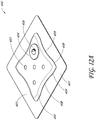
- FIGS 5A-F , 6A-F , 7A-F , 8A-F , 9A-F , 10A-F , 11A-F , 12A-F , and 24 illustrate additional embodiments of wound dressings.
- a waisted portion 408 is located inwardly with reference to an edge 409 of the absorbent layer 402.
- the contour of the absorbent layer 402 is curved from the edge 409 to the waisted portion 408, so as to form a smooth countour.
- Figures 5A-F illustrate multiple views of an embodiment of a wound dressing with a waisted portion, obscuring layer, and viewing windows.
- Figure 5A illustrates a perspective view of an embodiment of a wound dressing 400.
- the wound dressing 400 preferably comprises a port 406.
- the port 406 is preferably configured to be in fluid communication with a pump as described with reference to Figure 1 , and may include a tube or conduit pre-attached to the port.
- negative pressure can be supplied to the wound dressing through other suitable fluidic connectors, including but not limited to the fluidic connectors of the type described below in Figures 23A-B .
- the wound dressing 400 can be constructed similar to the embodiments of Figures 3A and 3B above, and may comprise an absorbent material 402 underneath or within a backing layer 405.
- a wound contact layer and a transmission layer may also be provided as part of the wound dressing 400 as described above.
- the absorbent material 402 can contain a narrowed central or waisted portion 408, as described previously to increase flexibility and conformability of the wound dressing to the skin surface.
- the backing layer 405 may have a border region 401 that extends beyond the periphery of the absorbent material 402.
- the backing layer 405 may be a translucent or transparent backing layer, such that the border region 401 created from the backing layer 405 can be translucent or transparent.
- the area of the border region 401 of the backing layer 405 can be approximately equal around the perimeter of the entire dressing with the exception of the narrowed central portion, where the area of the border region is larger.
- the size of the border region 401 will depend on the full dimensions of the dressing and any other design choices.
- an obscuring layer 404 that optionally has one or more viewing windows 403.
- the obscuring layer 404 may partially or completely obscure contents (such as fluids) contained within the wound dressing 400 and/or the absorbent material (i.e., within the absorbent material 402 or under the backing layer 405).
- the obscuring layer may be a colored portion of the absorbent material, or may be a separate layer that covers the absorbent material.
- the absorbent material 402 may be hidden (partially or completely), colored, or tinted, via the obscuring layer 404, so as to provide cosmetic and/or aesthetic enhancements, in a similar manner to what is described above.
- the obscuring layer is preferably provided between the topmost backing layer 405 and the absorbent material 402, although other configurations are possible.
- the cross-sectional view in Figure 3A and B illustrates this arrangement with respect to the masking or obscuring layer 2107.
- Other layers and other wound dressing components can be incorporated into the dressing as herein described.
- the obscuring layer 404 can be positioned at least partially over the absorbent material 402. In some embodiments, the obscuring layer 404 can be positioned adjacent to the backing layer, or can be positioned adjacent to any other dressing layer desired. In some embodiments, the obscuring layer 404 can be adhered to or integrally formed with the backing layer and/or the absorbent material.
- the obscuring layer 404 can help to reduce the unsightly appearance of a dressing during use, by using materials that impart partial obscuring or masking of the dressing surface.
- the obscuring layer 404 in one embodiment only partially obscures the dressing, to allow clinicians to access the information they require by observing the spread of exudate across the dressing surface.
- the partial masking nature of this embodiment of the obscuring layer enables a skilled clinician to perceive a different color caused by exudate, blood, by-products etc. in the dressing allowing for a visual assessment and monitoring of the extent of spread across the dressing.
- the change in color of the dressing from its clean state to a state containing exudate is only a slight change, the patient is unlikely to notice any aesthetic difference. Reducing or eliminating a visual indicator of wound exudate from a patient's wound is likely to have a positive effect on their health, reducing stress for example.
- the obscuring layer can be formed from a non-woven fabric (for example, polypropylene), and may be thermally bonded using a diamond pattern with 19% bond area.
- the obscuring layer can be hydrophobic or hydrophilic.
- a hydrophilic obscuring layer may provide added moisture vapor permeability.
- hydrophobic obscuring layers may still provide sufficient moisture vapor permeability (i.e., through appropriate material selection, thickness of the obscuring layer), while also permitting better retention of dye or color in the obscuring layer. As such, dye or color may be trapped beneath the obscuring layer.
- the absorbent layer 402 itself may be colored or tinted in some embodiments, however, so that an obscuring layer is not necessary.
- the dressing may optionally include a means of partially obscuring the top surface. This could also be achieved using a textile (knitted, woven, or non-woven) layer without openings, provided it still enables fluid evaporation from the absorbent structure. It could also be achieved by printing an obscuring pattern on the top film, or on the top surface of the uppermost pad component, using an appropriate ink or colored pad component (yarn, thread, coating) respectively. Another way of achieving this would be to have a completely opaque top surface, which could be temporarily opened by the clinician for inspection of the dressing state (for example through a window), and closed again without compromising the environment of the wound.
- Figure 5A illustrates an embodiment of the wound dressing including one or more viewing windows 403.
- the one or more viewing windows 403 preferably extend through the obscuring layer 404. These viewing windows 403 may allow visualization by a clinician or patient of the wound exudate in the absorbent material below the obscuring layer.
- Figure 5A illustrates an array of dots (e.g., in one or more parallel rows) that can serve as viewing windows 403 in the obscuring layer 404 of the wound dressing.
- two or more viewing windows 403 may be parallel with one or more sides of the dressing 400.
- the one or more viewing windows may measure between 0.1 mm and 20 mm, preferably 0.4 mm to 10 mm, and even more preferably, 1mm to 4 mm.
- the viewing windows 403 may be cut through the obscuring layer 404 or may be part of an uncolored area of the obscuring layer 404 and therefore may allow visualization of the absorbent material 402.
- the one or more viewing windows 403 can be arranged in a repeating pattern across the obscuring layer 404 or can be arranged at random across the obscuring layer. Additionally, the one or more viewing windows can be a circular shape or dots.
- the one or more viewing windows 403 are configured so as to permit not only the degree of saturation, but also the progression or spread of fluid toward the fluid port 406, as in some embodiments, dressing performance may be adversely affected when the level of fluid has saturated the fluid proximate the port 406.
- a "starburst" array of viewing windows 403 emanating around the port 406 may be suitable to show this progression, although of course other configurations are possible.
- the viewing windows 403 correspond to the area of the absorbent material 402 that is not covered by the obscuring layer 404. As such, the absorbent material 402 is directly adjacent the backing layer 405 in this area. Since the obscuring layer 404 acts as a partial obscuring layer, the viewing windows 403 may be used by a clinician or other trained user to assess the spread of wound exudate throughout the dressing. In some embodiments, the viewing windows 403 can comprise an array of dots or crescent shaped cut-outs.
- an array of dots as viewing windows 403 are illustrated in Figures 5A-F , 6A-F , 7A-F , 8A-F , 9A-F , 10A-F , 11A-F , and 12A-F in which the array of dots are arranged in an 5 x 2, 3 x 2, 8 x 1, 5 x 1, 3 x 1, 3 x 3, 3 x 3, and quincunx array respectively.
- the dot pattern can be distributed evenly throughout the obscuring layer and across the entire or substantially the entire surface of the obscuring layer.
- the viewing windows 403 may be distributed randomly throughout the obscuring layer.
- the area of the obscuring layer 404 uncovered by the one or more viewing windows 403 is balanced to as to minimize the appearance of exudate while permitting the inspection of the dressing 400 and/or absorbent material 402.
- the area exposed by the one or more viewing windows 403 does not exceed 20% of the area of the obscuring layer 404, preferably 10%, and even more preferably 5%.
- the viewing windows 403 may take several configurations, as will be discussed in relation to Figures 16-18 .
- the viewing windows 403 may comprise an array of regularly spaced uncolored dots (holes) made into the obscuring layer 404. While the dots illustrated here are in a particular pattern, the dots may be arranged in different configurations, or at random.
- the viewing windows 403 are preferably configured so as to permit a patient or caregiver to ascertain the status of the absorbent layer, in particular to determine its saturation level, as well as the color of the exudate (e.g., whether excessive blood is present). By having one or more viewing windows, the status of the absorbent layer can be determined in an unobtrusive manner that is not aesthetically unpleasing to a patient.
- the one or more viewing windows 403 may be used to provide a numerical assessment of the degree of saturation of the dressing 400. This may be done electronically (e.g., via a digital photograph assessment), or manually. For example, the degree of saturation may be monitored by counting the number of viewing windows 403 which may be obscured or tinted by exudate or other wound fluids.
- the absorbent layer 402 or the obscuring layer 404 may comprise (or be colored because of) the presence of an auxiliary compound.
- the auxiliary compound may in some embodiments be activated charcoal, which can act to absorb odors.
- the use of antimicrobial, antifungal, anti-inflammatory, and other such therapeutic compounds is also possible.
- the color may change as a function of time (e.g., to indicate when the dressing needs to be changed), if the dressing is saturated, or if the dressing has absorbed a certain amount of a harmful substance (e.g., to indicate the presence of infectious agents).
- the one or more viewing windows 403 may be monitored electronically, and may be used in conjunction with a computer program or system to alert a patient or physician to the saturation level of the dressing 400.
- Figure 16 illustrates an embodiment of a dressing containing a viewing window in the shape of a trademarked brand name ("PICO").
- Figure 18 illustrates an embodiment of a dressing comprising a viewing window in the shape of a logo, here, the Smith & Nephew logo.
- a logo here, the Smith & Nephew logo.
- the graphical or textual elements present in the viewing window may also be, for example, instructional in nature.
- instructions may be given to change the wound dressing when the exudate reaches a predetermined distance from the edge of the wound dressing, such as 5 mm from the wound dressing edge or 7 mm from the wound dressing edge, etc.
- a 'traffic light' system may be implemented whereby an electronic indicator shows green, amber or red light to indicate the spread of exudate in the wound dressing.
- another suitable indicator may be used for indicating the spread of exudate over the dressing.
- Figures 5A-F illustrate multiple views of the wound dressing 400.
- Figure 5A illustrates a perspective view of a wound dressing with the dimensions of 300mm x 150mm.
- Figures 5B and 5C illustrate a top view and bottom view of the embodiment of a wound dressing described in Figure 5A .
- Figures 5D and 5E illustrate a front and back view respectively of the wound dressing 400 described in Figure 5A .
- Figure 5F illustrates a side view of the wound dressing as described in Figure 5A .
- Embodiments of the wound dressings described herein may be arranged such that each embodiment may have enhanced compatibility with body movement. This can be achieved by using a different shape for different wound types or areas of the body.
- Wound dressing embodiments can be of any suitable shape or form or size as illustrated in Figures 5A-F , 6A-F , 7A-F , 8A-F , 9A-F , 10A-F , 11A-F , 12A-F , and 24A-F .
- the overall dimensions of the dressings as illustrated in Figures 5A-F , 6A-F , 7A-F , 8A-F , 9A-F , 10A-F , 11A-F , 12A-F may be, for example but without limitation, 300 mm x 150 mm, 200mm x 150 mm, 400 mm x 100 mm, 300 mm x 100 mm, 200mm x 100 mm, 250 mm x 250 mm, 200mm x 200mm, and 150 mm x 150mm, respectively, although any total size may be used, and the size may be determined to match particular wound sizes.
- the oval-shaped dressing in Figures 24A-F may, in some embodiments, measure 190mm x 230mm, or 145.5mm x 190 mm. Again, it will be understood that the embodiments described in the foregoing are simply illustrative embodiments illustrating possible sizes, dimensions, and configurations of wound dressings, and that other configurations are possible.
- the preceding embodiments illustrated in Figures 5A-F , 6A-F , 7A-F , 8A-F , 9A-F , 10A-F , 11A-F and 12A-F may comprise a waisted portion 408 located inwardly with reference to an edge 409 of the absorbent layer 402.
- the contour of the absorbent layer to the waisted portion 408 is preferably rounded and smooth.
- the inward distance between the edge 409 and the waisted portion 408 may range from 1mm, 5mm, 10mm, 15mm, 20mm, and 30mm.
- the inward distance is 10mm.
- the inward distance between the edge 409 and the waisted portion 408 may range from 5mm, 10mm, 20mm, 30mm, 40mm, 45mm, 50mm, 60mm, and 75mm.
- Figures 6A-F illustrate a perspective view, a top view, a bottom view, a front view, a back view, and a side view, respectively, of an embodiment of a wound dressing 400.
- the dressing may measure 200mm x 150mm.
- the wound dressing 400 of Figures 6A-F can have a similar configuration and components as described above for Figures 5A-F , except the embodiments of Figure 6A-F are of a smaller size. Additionally, in contrast to the embodiment of Figures 5A-F which comprises a 5 x 2 configuration of an array of dots viewing windows, the embodiment of Figures 6A-F comprises a viewing window configuration comprising a 3 x 2 array of dots.
- Figures 7A-F illustrate a perspective view, a top view, a bottom view, a front view, a back view, and a side view, respectively, of an embodiment of a wound dressing 400.
- the dressing may measure 400mm x 100mm.
- the wound dressing 400 of Figures 7A-F can have a similar configuration and components as described above for Figures 5A-F , except the embodiments of Figure 7A-F are of a different size.
- the embodiment of Figures 7A-F comprises a viewing window configuration comprising an 8 x 1 array of dots.
- Figures 8A-F illustrate a perspective view, a top view, a bottom view, a front view, a back view, and a side view, respectively, of an embodiment of a wound dressing 400.
- the dressing may measure 300mm x 100mm.
- the wound dressing 400 of Figures 8A-F can have a similar configuration and components as described above for Figures 5A-F , except the embodiments of Figure 8A-F are of a different size.
- the embodiment of Figures 8A-F comprises a viewing window configuration comprising a 5 x 1 array of dots.
- Figures 9A-F illustrate a perspective view, a top view, a bottom view, a front view, a back view, and a side view, respectively, of an embodiment of a wound dressing 400.
- the dressing may measure 200mm x 100mm.
- the wound dressing 400 of Figures 9A-F can have a similar configuration and components as described above for Figures 5A-F , except the embodiments of Figure 9A-F are of a different size.
- the embodiment of Figures 9A-F comprises a viewing window configuration comprising a 3 x 1 array of dots.
- Figures 12A-F illustrate a perspective view, a top view, a bottom view, a front view, a back view, and a side view, respectively, of an embodiment of a wound dressing 400.
- the dressing may measure 150mm x 150mm.
- the wound dressing 400 of Figures 12A-F can have a similar configuration and components as described above for Figures 5A-F , except the embodiments of Figure 9A-F are of a different size.
- the embodiment of Figures 12A-F comprises a viewing window configuration comprising a quincunx array of dots.
- the quincunx array of dots configuration consists of five dots arranged in a cross, with four of the dots forming a square or rectangle where one dot is positioned at each of the four corners of the square or rectangle shaped wound dressing and a fifth dot in the center.
- one corner of the wound dressing preferably has the fluidic connector or port 406 in place of a dot in the quincunx dot array.
- Figures 10A-F illustrate a perspective view, a top view, a bottom view, a front view, a back view, and a side view, respectively, of an embodiment of a wound dressing 400.
- the dressing may measure 250mm x 250mm.
- the wound dressing 400 of Figures 10A-F can have a similar configuration and components as described above for Figures 5A-F , except the embodiments of Figure 10A-F are of a different size.
- the embodiment of Figures 10A-F comprises a viewing window configuration comprising a 3 x 3 array of dots with an absent dot at a corner position of the wound dressing and in its place is a domed port or a fluidic connector 406 completing the 3 x 3 array.
- Figures 11A-F illustrate a perspective view, a top view, a bottom view, a front view, a back view, and a side view, respectively, of an embodiment of a wound dressing 400.
- the dressing may measure 200mm x 200mm.
- the wound dressing 400 of Figures 11A-F can have a similar configuration and components as described above for Figures 5A-F , except the embodiments of Figure 11A-F are of a different size.
- the embodiment of Figures 11A-F comprises a viewing window configuration comprising a 3 x 3 array of dots with an absent dot at a corner position of the wound dressing and in its place is a domed port or a fluidic connector completing the 3 x 3 array.
- Figures 13A, 13B , and 14 illustrate embodiments of a dressing 500 comprising one or more orifice viewing windows 502 at, near, or adjacent to the port.
- the orifice viewing windows 502 can be provided at, near, adjacent to the port 504 in the backing layer for viewing of the absorbent material 503 present in proximity to the port 504.
- the orifice viewing windows 502 can have the same structure and/or function as the viewing windows herein described.
- the orifice viewing window 502 can be formed from a cross-shaped or Maltese-cross-shaped aperture or cut-out 501 in the obscuring layer.
- the arms of the cross-shaped cut-out 501 can be aligned with the longitudinal length and transverse width of the absorbent material 503 as shown in Figure 13A .
- the arms of the cross-shaped cut-out 501 can be offset from the longitudinal length and transverse width of the absorbent material, at an angle, for example, a 45° angle, as illustrated in Figure 13B .
- the arms of the cross-shaped cut-out may span a larger dimension than a hole in the absorbent material below the cut-out 501.
- the arms may span a dimension of about 25 mm, while the through-hole in the absorbent material may have a diameter of 10 mm.
- Figure 14 illustrates an embodiment of a wound dressing 600 in which the arms of the cross-shaped aperture can have flared edges 601.
- the orifice viewing windows 502 at, near, or adjacent to the port 604 may be used to indicate that fluid is approaching the port 604 or that the dressing 600 is otherwise becoming saturated. This can assist the clinician or patient in maintaining the wound dressing and determining when to change the dressing, because once fluid contacts the center of the port, such fluid contact may at least partially occlude the hydrophobic filter that may be contained therein so as to interrupt or at least partially block the application of negative pressure.
- the orifice viewing windows 502 can be used with the fluidic connector as well as the domed port or any other suitable connector.
- the wound dressing may also be provided with one or more slits 2150 to aid the dressing in conforming to a non-planar area.
- Figure 15A illustrates an embodiment of a wound dressing 2100 with a narrowed central portion or waisted portion 2120 and concentric slits 2150. This embodiment may be useful for the treatment of wounds on non-planar surfaces or otherwise contoured wounds, including, for example, feet, knees, sacral regions, or other such areas.
- the wound dressing 2100 may provide for one or more slits 2150 cut into the dressing, preferably into the absorbent layer, that may enhance the conformability of the dressing.
- the slits 2150 are cut in concentric ovoid arcs, although other configurations (as discussed below) are possible.
- the area under the port 2130 or fluidic connector disposed at the top of the device is free from the slits 2150, as this may interfere with fluid transfer from the dressing.
- the slits 2150 may be formed as part of, in addition to, or instead of baffles that may be present within the absorbent layer so as to may aid in distribution of wound exudate.
- a domed connector is shown attached to the dressing, this may be interchanged with any other suitable connector, including for example embodiments of the fluidic connectors described in Figures 23A and 23B (as described below).
- Figure 15B illustrates an embodiment of a wound dressing 2100 with a narrow central portion 2120.
- one or more slits 2150 extending across the width of the dressing may be present.
- these slits 2150 do not extend entirely across the width of the dressing, in order to promote fluid transfer within the absorbent layer.
- the slits 2150 may enhance conformability of the dressing, possibly in conjunction with the waisted configuration of the dressing, when applied to a non-planar or contoured wound area.
- such a dressing 2100 may be useful when applied so as to wrap around an arm or a leg.
- Figures 23A and 23B illustrate embodiments of white and black fluidic connectors 2410, 2420, respectively, that may be used to connect an embodiment of a wound dressing described herein to a source of negative pressure.
- the domed port used in other embodiments discussed herein may be replaced by the fluidic connector 2410, 2420, for example as illustrated in Figures 16-19 .
- the fluidic connector 2410, 2420 may be flexible and/or enhance the comfort of the patient.
- the fluidic connector 2410, 2420 preferably comprises a fluidic connector body configured to transmit fluid through itself, including, for example, negative pressure and/or wound exudate.
- the fluidic connector body is preferably encapsulated within one or more layers of fluid-impermeable material.
- the fluid-impermeable material is heat-sealed together to enclose the fluid connector body.
- the body of the fluidic connector 2410 is preferably be constructed from a material configured to transmit fluids therethrough, including fabrics such as 3D fabric.
- the thickness of the fluidic connector body may measure between 0.5 to 4mm, preferably 0.7 to 3mm, and even more preferably between 1 and 2mm; in a preferred embodiment the fluid connector body is 1.5mm thick.
- Suitable materials that may be used for the fluidic connector body, including the 3D fabric, are disclosed in U.S. Application 13/381,885, filed December 30, 2011 , published as US2012/0116334 , titled "APPARATUSES AND METHODS FOR NEGATIVE PRESSURE WOUND THERAPY,” and which is hereby incorporated by reference in its entirety.
- Use of the 3D fabric in the fluidic connector body may help alleviate fluid blockage when the connector is kinked, and may further provide for a soft fluidic connector that alleviates contact pressure onto a patient, for example when the patient's weight is pressed against the fluidic connector. This may enhance patient comfort and reduce the likelihood of pressure ulcers.
- embodiments of the fluidic connectors described herein can transmit therapeutic levels of negative pressure (i.e., in an amount sufficient to heal a wound) while a weight is pressed down thereupon.
- embodiments are preferably able to transmit therapeutic levels of negative pressure while an external pressure applied on the dressing and/or 3D fabric of up to 1 kg/cm 2 , preferably up to 2 kg/cm 2 , and even more preferably up to 4 kg/cm 2 .
- Certain embodiments, as described below, have been tested as being capable of transmitting therapeutic levels of negative pressure while an external pressure applied on the dressing and/or 3D fabric is above 6 kg/cm 2 .
- a 400ml wound cavity was used, and pressure was measured both at the wound and at the pump.
- Embodiments of a fluidic connector comprising 3D fabric were tested when laid flat with a weight placed thereupon. Testing indicated that when no pressure was applied to the fluidic connector, the pressure differential between the pressure at the pump and at the cavity was approximately 2 mmHg.
- Various different weights were applied, ranging between 2 and 12 kg/cm 2 , in 2 kg increments, and the resulting pressure difference was approximately linear, with the pressure difference at 12 kg/cm 2 being calculated at 33 mmHg, while the pressure difference at 2 kg/cm 2 being only 16mmHg.
- the relation between the pressure difference in mmHg was found to equal approximately 4.5 times the applied load in kg/cm 2 . Testing also indicated that the relative pressure difference between the pressure at the pump and the pressure at the wound after five minutes was less than 10 mmHg when measured at the pump for loads under 4 kg/cm 2 , and under 20 mmHg when measured at the wound for loads under 4 kg/cm 2 .
- the maximum negative pressure that could be applied using 3D fabric measuring 1, 1.25, 1.5, 1.75, and 2 cm in width was found to be between 85 and 92 mmHg, respectively.
- the maximum negative pressure applied for a 1cm-width embodiment dropped to 75mmHg, while the 1.25 and 1.5 cm-width embodiments were essentially unchanged, exhibiting pressures between 85 and 90 mmHg.
- using wider and/or thicker 3D fabric may permit improved air flow, together with greater pressure and kink resistance in some context; this may be useful especially if higher absolute negative pressure need to be applied to the wound.
- the greater kink and pressure resistance may need to be balanced with other concerns such as perceived bulk and size of the fluidic connector, aesthetics, and comfort, which may require use of a thinner 3D fabric.
- the proximal end 2411 of the fluidic connector 2410 is configured to be connected to a tube or other conduit that is in fluid communication with a source of negative pressure via the fluid connector body, although some embodiments may provide for the fluidic connector 2410 to be directly connectable to a source of negative pressure without needing a conventional tube.
- the distal end 2412 of the fluidic connector 2410 may be enlarged, and is configured to be attached and/or adhered to a dressing, for example via an aperture in the backing layer of the dressing and/or in the fluidic connector 2410, so that the fluid connector body is in fluid communication therewith.
- the distal end 2412 of the fluidic connector 2410 may be convex on one side and flat on the opposite side. As illustrated in Figures 16-18 below, the flat side may be aligned with the edge of the absorbent layer with the convex side extending over the aperture in the backing layer.
- the fluidic connector 2410 may be provided preattached to the dressing portion, or may be provided in an unattached format so as to be connectable to the dressing portion by the patient or caregiver.
- the enlarged distal end 2412 may aid in providing a larger area capable of transmitting negative pressure to the dressing, although the distal end may be provided without any enlargement.
- the fluidic connector 2410 may be configured so as to transfer exudate in addition to air.
- the distal end of the fluidic connector is preferably provided with a filter configured to block fluid transport beyond itself, such as a hydrophobic filter.
- the fluidic connector may be provided with a secondary air leak channel configured to provide a flow of ambient air to the wound site.
- the secondary air leak channel is provided with a filter to prevent contamination of the wound.
- Figure 23B this figure shows an embodiment similar to Figure 23A , but where the fluidic connector 2420 may appear colored, for example as a result of an obscuring layer similar to that previously described.
- obscuring coloration may be provided by dyeing the material used in the fluidic connector 2420, for example the 3D fabric that may be used therein.
- the obscuring layer may be placed above the 3D fabric, either above or below the fluid-impermeable material.
- the encapsulating fluid-impermeable material may be colored or tinted.
- Coloring the fluidic connector 2420 may enhance the aesthetic appeal of the device, help in disguising or making the device less obtrusive (in particular when the fluidic connector is visible to others), and, when the fluidic connector is used to transfer exudates away from the wound, may hide the presence of the exudates therein.
- FIG 17 illustrates an embodiment of a wound dressing 720 that comprises a hexagonal backing layer and a three-lobed configuration for the absorbent material and the obscuring layer.
- This wound dressing 720 may be advantageously applied to wounds or areas surrounding wounds that are located in non-planar areas.
- the embodiment illustrated here may be particularly advantageous when applied to protruding body portions, for example elbows and heels.
- Figure 18 illustrates a wound dressing 730 with a three-lobed configuration similar in some respects to the embodiment illustrated in Figure 17 .
- the dressing is smaller and comprises more rounded projections.
- Figures 16-18 illustrate a fluidic connector 721, 731 similar to those described in Figures 23A and 23B attached to the device, with the flat end aligned with the edge of the absorbent material and the convex end extending over an aperture in the backing layer.
- This fluidic connector may enhance comfort and prevent pressure ulcers or other complications that may result from extended pressure of a conventional tube onto the wound or skin surrounding the wound (as described above).
- different connectors may be used, such as the domed port illustrated in Figure 1 .
- Figures 19-20 also illustrate additional embodiments of wound dressings 740, 750 with three-lobed configurations for the absorbent material and a hexagonal backing layer.
- the wound dressing 750 illustrated in Figure 20 is larger where the lobes of the absorbent material comprises flared ends, while the wound dressing 740 illustrated in Figure 19 is smaller and the absorbent material does not have flared ends.
- All suitable fluidic connectors or conduits may be used, and the domed port connector of Figure 20 may be used in place of the fluidic connector of Figure 19 , and vice versa.
- the absorbent layers may be colored or obscured, and one or more slits may be formed onto the absorbent layers to enhance conformability to non-planar surfaces. It will be appreciated that in the embodiments of Figures 17-20 , the number of lobes may be varied, and the backing layer can have other shapes, and is not limited to being hexagonal.
- Figures 21A-C and 22 illustrate embodiments of a wound dressing 760, 770, 780, 790 that comprises a four-lobed configuration. Although these embodiments are illustrated without a port or fluidic connector attached thereto, it will of course be understood that such ports and fluidic connectors are envisioned and may be attached in a similar fashion as described previously herein.
- Figures 21A-C comprise embodiments of a four-lobed wound dressing comprising an obscuring layer and viewing windows extending through the obscuring layer. The viewing windows can be used as discussed above for visualization of wound exudate in the absorbent layer. Examples of such viewing windows are illustrated in Figures 21A and 21B .
- the dressing 760 shown in Figure 21A includes an obscuring layer 762 and crescent-shaped viewing windows 764 provided in the obscuring layer to extend through the obscuring layer allowing visibility of the dressing therebelow.
- the dressing 770 of Figure 21B includes an obscuring layer 772 and a number of holes 774 therethrough acting as viewing windows for viewing the state of the dressing therebelow.
- Figure 21C shows another dressing 780 including an obscuring layer 782 with viewing windows 784.
- Figure 22 illustrates a perspective view of an embodiment of a wound dressing 790 according to an embodiment of the four-lobe configuration.
- Figure 22 shows a possible four-lobe configuration of a dressing, useful for enhanced compatibility with body movement, where each layer is shaped to reduce the incident angle of the pad edge, and to provide somewhat independently moving sub-sections of the dressing.
- the dressing border including the wound contact layer 791 and the backing layer 792 can also comprise slits, provided to further enhance the conformability on application by allowing the borders to overlap if needed.
- the wound dressing with a four-lobe configuration, as well as other configurations, are described in detail in International Application PCT/GB2012/000587 , titled “WOUND DRESSING AND METHOD OF TREATMENT” and filed on July 12, 2012. which is incorporated by reference herein.
- Figures 24A-F illustrate an embodiment of a wound dressing 2300 with an oval shaped absorbent layer 2308 having multiple lobes 2301.
- Figures 24A-F illustrate, respectively, perspective, top, bottom, left, right, and side views of an embodiment of the dressing 2300.
- the absorbent layer 2308 can have six lobes.
- two or more lobes 2301 e.g., six lobes
- the lobes 2301 are provided on the wound dressing 2300; the lobes 2301, and specifically, the gaps between the lobes 2301, aid the wound dressing 2300 in conforming to nonplanar wounds.
- the dressing 2300 can have a rectangular or square shaped backing layer 2302, and in some embodiments, the overall dressing 2300 may measure 190mm x 230mm, or 145.5mm x 190 mm.
- a fluidic connector such as a port 2306 is attached to the dressing 2300, although it will of be recognized that the fluidic connector of Figures 23A-B may be used instead or in addition.
- the dressing 2300 can have an obscuring layer 2304 and one or more viewing windows 2303 similar to that described for other embodiments herein.
- Figure 24A illustrates a perspective view of the dressing 2300
- Figure 24B illustrates a top view, 24C a bottom view, and 24D-F represent views of the four sides of the dressing 2300.
- Figure 25 illustrates an embodiment similar in shape and overall configuration to the embodiments illustrated above in Figures 7A-F .
- the dressing 500 comprises an orifice viewing window 502 similar to that described in relation to Figures 13A-B and 14 .
- the orifice viewing window 502 is preferably formed from a cross-shaped or Maltese-cross shaped aperture or cutout 501 in the obscuring layer 506.
- the backing layer 510 provided over the obscuring layer preferably has an orifice 504 located at the center of the orifice viewing window 502.
- Reference number 504 can also be considered to designate a port that may be provided in or over the backing layer 510 to provide a connection to a source of negative pressure, for example, a port provided over the orifice in the backing layer as described above.
- a smaller orifice 505 may be located in the absorbent layer 503 that is provided below the obscuring layer 506.
- the dressing 500 may comprise one or more viewing windows 507; here, eight viewing windows 507 are provided in a linear arrangement.
- the bottom side of the dressing 500 optionally comprises a layer of adhesive, over which a release layer 513 may be placed. Lines 512 illustrate possible locations where breaks in the release liner 513 may be provided.
- the dressing 500 illustrated here has a longitudinal length of approximately 400 mm, and a transverse width of approximately 100 mm.
- the central axis of each arm of the cutout 501 of the orifice viewing window 502 is preferably offset from the longitudinal length and transverse width of the absorbent material, at an angle, for example, a 45° angle, as illustrated.
- the spacing between each arm of the cutout 501 may be, as illustrated here, 72°, although it will of course be recognized that other angles and configurations are possible.
- Lines 512, indicating possible locations where breaks in the release liner 513 may be provided, can be located, for example, at 80mm, 40 ⁇ 4mm, and 25 ⁇ 4mm from each of the top and bottom edges of the dressing 500.
- the orifice or port 504 (and cutout 501) are preferably centered on the transverse midline of the dressing 500, and situated approximately 52-55mm from the top edge of the dressing 500. Although the location may be changed, it may be preferable to locate the port 504 near or along a side, edge, or corner of the dressing 500, which is then preferably elevated with respect to the remainder of the dressing. This configuration may extend the life of the dressing, as fluid would be slower in saturating the absorbent layer below or near the orifice or port 504.
- Figure 26 illustrates an embodiment similar in shape and overall configuration to the embodiments illustrated above in Figures 8A-F .
- the dressing 500 comprises an orifice viewing window 502 and cutout 501, with for example five linearly arranged viewing windows 507, among other parts, that are similar to that described above in relation to Figure 25 .
- the dressing 500 illustrated here has a longitudinal length of approximately 300 mm, and a transverse width of approximately 100 mm.
- the spacing between each arm of the cutout 501 may be, as illustrated here, 72°, although it will of course be recognized that other angles and configurations are possible.
- Lines 512 indicating possible locations where breaks in the release liner 513 may be provided, can be located, for example, at 80mm, 40 ⁇ 4mm, and 25 ⁇ 4mm from each of the top and bottom edges of the dressing 500.
- the orifice or port 504 (and cutout 501) are preferably centered on the transverse midline of the dressing 500, and situated approximately 52-55mm from the top edge of the dressing 500.
- Figure 27 illustrates an embodiment similar in shape and overall configuration to the embodiments illustrated above in Figures 9A-F .
- the dressing 500 comprises an orifice viewing window 502 and cutout 501, with for example three linearly arranged viewing windows 507, among other parts, that are similar to that described above in relation to Figure 25 .
- the dressing 500 illustrated here has a longitudinal length of approximately 200 mm, and a transverse width of approximately 100 mm.
- the spacing between each arm of the cutout 501 may be, as illustrated here, 72°, although it will of course be recognized that other angles and configurations are possible.
- Lines 512 indicating possible locations where breaks in the release liner 513 may be provided, can be located, for example, at 80mm, 40 ⁇ 4mm, and 25 ⁇ 4mm from each of the top and bottom edges of the dressing 500.
- the orifice or port 504 (and cutout 501) are preferably centered on the transverse midline of the dressing 500, and situated approximately 52-55mm from the top edge of the dressing 500.
- Figure 28 illustrates an embodiment similar in shape and overall configuration to the embodiments illustrated above in Figures 5A-F .
- the dressing 500 comprises an orifice viewing window 502 and cutout 501, with for example two rows of five linearly arranged viewing windows 507, among other parts, that are similar to that described above in relation to Figure 25 .
- the dressing 500 illustrated here has a longitudinal length of approximately 300 mm, and a transverse width of approximately 150 mm.
- the spacing between each arm of the cutout 501 may be, as illustrated here, 72°, although it will of course be recognized that other angles and configurations are possible.
- Lines 512 indicating possible locations where breaks in the release liner 513 may be provided, can be located, for example, at 80mm, 40 ⁇ 4mm, and 25 ⁇ 4mm from each of the top and bottom edges of the dressing 500.
- the orifice or port 504 (and cutout 501) are preferably centered on the transverse midline of the dressing 500, and situated approximately 52-55mm from the top edge of the dressing 500.
- Figure 29 illustrates an embodiment similar in shape and overall configuration to the embodiments illustrated above in Figures 6A-F .
- the dressing 500 comprises an orifice viewing window 502 and cutout 501, with for example two rows of three linearly arranged viewing windows 507, among other parts, that are similar to that described above in relation to Figure 25 .
- the dressing 500 illustrated here has a longitudinal length of approximately 300 mm, and a transverse width of approximately 100 mm.
- the spacing between each arm of the cutout 501 may be, as illustrated here, 72°, although it will of course be recognized that other angles and configurations are possible.
- Lines 512 indicating possible locations where breaks in the release liner 513 may be provided, can be located, for example, at 80mm, 40 ⁇ 4mm, and 25 ⁇ 4mm from each of the top and bottom edges of the dressing 500.
- the orifice or port 504 (and cutout 501) are preferably centered on the transverse midline of the dressing 500, and situated approximately 52-55mm from the top edge of the dressing 500.
- Figure 30 illustrates an embodiment similar in shape and overall configuration to the embodiments illustrated above in Figures 10A-F .
- the dressing 500 comprises an orifice viewing window 502 and cutout 501, with a 3 x 3 array of viewing windows absent a viewing window at a corner position of the wound dressing, among other parts, that are similar to that described above in relation to Figure 25 but located in a corner of the dressing 500.
- the dressing 500 illustrated here is approximately square, with each side measuring approximately 250mm.
- the spacing between each arm of the cutout 501 may be, as illustrated here, 72°, although it will of course be recognized that other angles and configurations are possible.
- Lines 512 indicating possible locations where breaks in the release liner 513 may be provided, can be located, for example, at 80mm, 40 ⁇ 4mm, and 25 ⁇ 4mm from each of the top and bottom edges of the dressing 500.
- the orifice or port 504 (and cutout 501) are preferably centered on a corner of the dressing 500, and situated approximately 52-55mm from the top edge of the dressing 500.
- Figure 31 illustrates an embodiment similar in shape and overall configuration to the embodiments illustrated above in Figures 11A-F .
- the dressing 500 comprises an orifice viewing window 502 and cutout 501, with a 3 x 3 array of viewing windows absent a viewing window at a corner position of the wound dressing, among other parts, that are similar to that described above in relation to Figure 25 but located in a corner of the dressing 500.
- the dressing 500 illustrated here is approximately square, with each side measuring approximately 200mm.
- the spacing between each arm of the cutout 501 may be, as illustrated here, 72°, although it will of course be recognized that other angles and configurations are possible.
- Lines 512 indicating possible locations where breaks in the release liner 513 may be provided, can be located, for example, at 80mm, 40 ⁇ 4mm, and 25 ⁇ 4mm from each of the top and bottom edges of the dressing 500.
- the orifice or port 504 (and cutout 501) are preferably centered on a corner of the dressing 500, and situated approximately 52-55mm from the top edge of the dressing 500.
- Figure 32 illustrates an embodiment similar in shape and overall configuration to the embodiments illustrated above in Figures 12A-F .
- the dressing 500 comprises an orifice viewing window 502 and cutout 501, with a quincunx array of viewing windows absent a viewing window at a corner position of the wound dressing, among other parts, that are similar to that described above in relation to Figure 25 but located in a corner of the dressing 500.
- the dressing 500 illustrated here is approximately square, with each side measuring approximately 150mm.
- the spacing between each arm of the cutout 501 may be, as illustrated here, 72°, although it will of course be recognized that other angles and configurations are possible.
- Lines 512 indicating possible locations where breaks in the release liner 513 may be provided, can be located, for example, at 80mm, 40 ⁇ 4mm, and 25 ⁇ 4mm from each of the top and bottom edges of the dressing 500.
- the port 504 (and cutout 501) are preferably centered on a corner of the dressing 500, and situated approximately 52-55mm from the top edge of the dressing 500.
- Figure 33A-B illustrates an embodiment somewhat similar in shape and overall configuration to the embodiments illustrated above in Figures 24A-F .
- the oval-shaped dressing 500 comprises an orifice viewing window 502 and cutout 501, among other parts, that are similar to that described above in relation to Figure 25 . Viewing windows are not shown, but may be provided as in one embodiment as described above.
- the dressing 500 illustrated in Figure 33A has a longitudinal length of approximately 250 mm, and a transverse width of approximately 200 mm.
- the longitudinal length of the absorbent layer 503 (and corresponding obscuring layer, if so provided) measures approximately 200 mm, with a transverse width of approximately 150mm.
- the embodiment of the dressing 500 illustrated in Figure 33B has a longitudinal length of approximately 200 mm, and a transverse width of approximately 150 mm.
- the longitudinal length of the absorbent layer 503 (and corresponding obscuring layer, if so provided) measures approximately 150 mm, with a transverse width of approximately 100 mm.
- no viewing windows 507 are illustrated, it will of course be understood that one or more such windows 507 may be provided on the dressing 500.
- the spacing between each arm of the cutout 501 may be 72°, although it will of course be recognized that other angles and configurations are possible.
- the orifice or port 504 (and cutout 501) are preferably centered on the transverse midline of the dressing 500, and situated approximately 52-55mm from the top edge of the dressing 500.
- Figure 34A illustrates an exploded view of a dressing 3400 for use in negative pressure wound therapy.
- the dressing 3400 comprises a release layer 3480, wound contact layer 3460, a transmission layer 3450, an acquisition distribution layer 3440, an absorbent layer 3430, an obscuring layer 3420, and a backing layer 3410.
- the dressing 3400 may be connected to a port, such as described below with respect to Figures 35 and 36 .
- At least the wound contact layer 3460, transmission layer 3450, absorbent layer 3430, obscuring layer 3420, and backing layer 3410 may have properties as described with respect to particular embodiments above, such as the embodiments of Figures 3A-22 , and 24A-33B , as well as or instead of the properties described below.
- the dressing 3400 may comprise a wound contact layer 3460 for sealing the dressing 3400 to the healthy skin of a patient surrounding a wound area.
- Certain embodiments of the wound contact layer may comprise three layers: a polyurethane film layer, a lower adhesive layer and an upper adhesive layer.
- the upper adhesive layer may assist in maintaining the integrity of the dressing 3400, and the lower adhesive layer may be employed for sealing the dressing 3400 to the healthy skin of a patient around a wound site.
- some embodiments of the polyurethane film layer may be perforated.
- Some embodiments of the polyurethane film layer and upper and lower adhesive layers may be perforated together after the adhesive layers have been applied to the polyurethane film.
- a pressure sensitive adhesive which may be a silicone, hot melt, hydrocolloid or acrylic based adhesive or other such adhesives, may be formed on both sides or optionally on a selected one side of the wound contact layer.
- the upper adhesive layer may comprise an acrylic pressure sensitive adhesive
- the lower adhesive layer may comprise a silicone pressure sensitive adhesive.
- the wound contact layer 3460 may not be provided with adhesive.
- the wound contact layer 3460 may be transparent or translucent.
- the film layer of the wound contact layer 3460 may define a perimeter with a rectangular or a square shape.
- a release layer 3480 may be removably attached to the underside of the wound contact layer 3460, for example covering the lower adhesive layer, and may be peeled off using flaps 3481. Some embodiments of the release layer 3480 may have a plurality of flaps extending along the length of the layer 3480.
- the dressing 3400 may comprise an optional spacer or transmission layer 3450.
- the transmission layer 3450 may comprise a porous material or 3D fabric configured to allow for the passage of fluids therethrough away from the wound site and into the upper layers of the dressing 3400.
- the transmission layer 3450 can ensure that an open air channel can be maintained to communicate negative pressure over the wound area even when the absorbent layer 3430 has absorbed substantial amounts of exudates.
- the transmission layer 3450 should remain open under the typical pressures that will be applied during negative pressure wound therapy as described above, so that the whole wound site sees an equalized negative pressure.
- the transmission layer 3450 may be formed of a material having a three dimensional structure.
- a knitted or woven spacer fabric for example Baltex 7970 weft knitted polyester
- a non-woven fabric can be used.
- the transmission layer 3450 can have a 3D polyester spacer fabric layer. This layer can have a top layer which is a 84/144 textured polyester, and a bottom layer which can be a 100 denier flat polyester and a third layer formed sandwiched between these two layers which is a region defined by a knitted polyester viscose, cellulose or the like monofilament fiber.
- this differential between filament counts in the spaced apart layers tends to draw liquid away from the wound bed and into a central region of the dressing 3400 where the absorbent layer 3430 helps lock the liquid away or itself wicks the liquid onwards towards the cover layer 3410 where it can be transpired.
- Other materials can be utilized, and examples of such materials are described in U.S. Patent Pub. No. 2011/0282309 , which are hereby incorporated by reference and made part of this disclosure.
- the transmission layer 3450 may be optional, and for example may be optional in embodiments of the dressing 3400 which comprise the acquisition distribution layer 3440, described below.
- Some embodiments may comprise a wicking or acquisition distribution layer (ADL) 3440 to horizontally wick fluid such as wound exudate as it is absorbed upward through the layers of the dressing 3400. Lateral wicking of fluid may allow maximum distribution of the fluid through the absorbent layer 3430 and may enable the absorbent layer 3430 to reach its full holding capacity. This may advantageously increase moisture vapor permeation and efficient delivery of negative pressure to the wound site.
- ADL 3440 may comprise viscose, polyester, polypropylene, cellulose, or a combination of some or all of these, and the material may be needle-punched.
- Some embodiments of the ADL 3440 may comprise polyethylene in the range of 40-150 grams per square meter (gsm).
- the dressing 3400 may further comprise an absorbent or superabsorbent layer 3430.
- the absorbent layer can be manufactured from ALLEVYNTM foam, Freudenberg 114-224-4 and/or Chem-PositeTM11C-450, or any other suitable material.
- the absorbent layer 3430 can be a layer of non-woven cellulose fibers having super-absorbent material in the form of dry particles dispersed throughout. Use of the cellulose fibers introduces fast wicking elements which help quickly and evenly distribute liquid taken up by the dressing. The juxtaposition of multiple strand-like fibers leads to strong capillary action in the fibrous pad which helps distribute liquid.
- the absorbent layer 3430 may comprise a layered construction of an upper layer of non-woven cellulose fibers, superabsorbent particles (SAP), and a lower layer of cellulose fibers with 40-80% SAP.
- the absorbent layer 3430 may be an air-laid material. Heat fusible fibers can optionally be used to assist in holding the structure of the pad together.
- Some embodiments may combine cellulose fibers and air-laid materials, and may further comprise up to 60% SAP. Some embodiments may comprise 60% SAP and 40% cellulose.
- Other embodiments of the absorbent layer may comprise between 60% and 90% (or between about 60% and about 90%) cellulose matrix and between 10% and 40% (or between about 10% and about 40%) superabsorbent particles.
- the absorbent layer may have about 20% superabsorbent material and about 80% cellulose fibers. It will be appreciated that rather than using super-absorbing particles or in addition to such use, super-absorbing fibers can be utilized according to some embodiments of the present invention.
- An example of a suitable material is the Product Chem-PositeTM 11 C available from Emerging Technologies Inc (ETi) in the USA.
- Super-absorber particles/fibers can be, for example, sodium polyacrylate or carbomethoxycellulose materials or the like or any material capable of absorbing many times its own weight in liquid.
- the material can absorb more than five times its own weight of 0.9% W/W saline, etc.
- the material can absorb more than 15 times its own weight of 0.9% W/W saline, etc.
- the material is capable of absorbing more than 20 times its own weight of 0.9% W/W saline, etc.
- the material is capable of absorbing more than 30 times its own weight of 0.9% W/W saline, etc.
- the absorbent layer 3430 can have one or more through holes 3431 located so as to underlie the suction port.
- Some embodiments of the present disclosure may employ a masking or obscuring layer 3420 to help reduce the unsightly appearance of a dressing 3400 during use due to the absorption of wound exudate.
- the obscuring layer 3420 may be a colored portion of the absorbent material, or may be a separate layer that covers the absorbent material.
- the obscuring layer 3420 may be one of a variety of colors such as blue, orange, yellow, green, or any color suitable for masking the presence of wound exudate in the dressing 3400.
- a blue obscuring layer 3420 may be a shade of blue similar to the shade of blue commonly used for the material of medical gowns, scrubs, and drapes.
- Some embodiments of the obscuring layer 3420 may comprise polypropylene spunbond material.
- some embodiments of the obscuring layer 3420 may comprise a hydrophobic additive or coating.
- Other embodiments may comprise a thin fibrous sheet of 60, 70, or 80 gsm.
- the obscuring layer may comprise at least one viewing window 3422 configured to allow a visual determination of the saturation level of the absorbent layer.
- the at least one viewing window 3422 may comprise at least one aperture made through the obscuring layer.
- the at least one viewing window 3422 may comprise at least one uncolored region of the obscuring layer.
- Some embodiments of the obscuring layer may comprise a plurality of viewing windows or an array of viewing windows, as discussed above with respect to Figures 25-32 .
- the masking capabilities of the obscuring layer 3420 should preferably only be partial, to allow clinicians to access the information they require by observing the spread of exudate across the dressing surface.
- a obscuring layer 3420 may be partial due to material properties allowing wound exudate to slightly alter the appearance of the dressing or due to the presence of at least one viewing window 3422 in a completely obscuring material.
- the partial masking nature of the obscuring layer 3420 enables a skilled clinician to perceive a different colour caused by exudate, blood, by-products etc. in the dressing allowing for a visual assessment and monitoring of the extent of spread across the dressing.
- Tests performed upon various dressings with respect to the transmittance properties of the dressing indicate the ability of various samples to mask colour.
- the ability to mask colour may be calculated, for example, by measuring the reduction in absorption of light radiation at particular wavelengths.
- the tests utilized a UV-Vis spectrophotometer Jasco with integrating sphere, with a scanning range 340 to 800 nm, bandwidth 5nm and 1000nm/sec scanning speed.
- the data labelled black background represents the extreme of exudate colour (the most colour an exudate might have) - the highest level of radiation absorbed and the least amount of radiation reflected from the sample.
- the data for white background represents the upper limit for total masking - generally the lowest level of radiation absorbed and the highest level of reflection.
- Sample 1 was a tinted polymer film placed over a black background, which was judged not to sufficiently mask the black background (representing wound exudate) satisfactorily.
- Sample 2 was a sheet of 3-dimensional spacer fabric (Baltex 3D) placed over a black background, and was judged to provide adequate masking of the black background.
- Sample 3 was a sheet of non-woven material dyed green placed over a black background, and provided complete masking of the black background.
- Wound exudate may have dark yellow, red and/or brown tones. Therefore, to appropriately mask these colours, an obscuring layer 3420 would preferably shield light wavelengths of below 600 nm.
- a complete masking element would preferably require a means for a clinician to judge the spread of wound exudate in the dressing below the obscuring layer 3420, e.g. the masking element not completely covering the entire dressing.
- a plurality of viewing windows may be provided in the obscuring layer 3420 such that the spread of exudate in the dressing below may be adequately assessed.
- a partial masking element may allow a clinician to judge the spread of exudate in the dressing below without additional means.
- completely opaque masking layers such as for example a tinted polymeric film, may cover the area to be masked with a darker tone altogether, in which case the measure of L* is not relevant.
- the color of the obscuring layer 3420 may affect the masking ability of the layer.
- various colors are suitable for masking the usual colors of wound exudate, while other colors may not provide optimal masking of the exudate.
- some embodiments of the obscuring layer, in a dry state may be configured to yield a CIE y value of .4 or less and a CIE x value of .5 or less.
- Some embodiments of the obscuring layer in a dry state, may have a color of Bg, gB, B, pB, bP, P, rP, pPk, RP, O, rO, or yO on the CIE x, y chromaticity diagram. It will be appreciated that liquid impermeable embodiments of the obscuring layer may be configured with any color.
- the obscuring layer 3420 can have one or more through holes located so as to underlie the suction port.
- Some embodiments may have a maltese cross 3421 or other shaped cutout underlying the suction port, wherein the diameter of the maltese cross 3421 is greater than the diameter of the port. This may allow a clinician to easily asses the amount of wound exudate absorbed into the layers beneath the port.
- the dressing 3400 may also comprise a backing layer, or cover layer 3410 extending across the width of the wound dressing.
- the cover layer 3410 may be gas impermeable but moisture vapor permeable.
- Some embodiments may employ a polyurethane film (for example, Elastollan SP9109) or any other suitable material.
- certain embodiments may comprise translucent or transparent 30gsm EU33 film.
- the cover layer 3410 may have a pressure sensitive adhesive on the lower side, thereby creating a substantially sealed enclosure over the wound in which negative pressure may be established.
- the cover layer can protect the wound as a bacterial barrier from external contamination, and may allow liquid from wound exudates to be transferred through the layer and evaporated from the film outer surface.
- the cover layer 3410 can have an orifice 3411 located so as to underlie the suction port.
- the orifice 3411 may allow transmission of negative pressure through the cover layer 3410 to the wound enclosure.
- the port may be adhered and sealed to the cover film using an adhesive such as an acrylic, cyanoacrylate, epoxy, UV curable or hot melt adhesive.
- Some embodiments may have a plurality of orifices for the attachment of multiple ports or other sources of negative pressure or other mechanisms for distributing fluid.
- Figure 34B illustrates a cross sectional view of the wound dressing 3400, displaying an embodiment of the relative thicknesses of layers of the dressing 3400.
- the wound contact layer 3460 may be flat and the top film layer 3410 may be contoured over the inner layers of the dressing 3400.
- the spacer layer 3450 may be half as thick as the acquisition distribution layer 3440 in some embodiments.
- the absorbent layer 3430 may be about 1.5 times thicker than the spacer layer 3450.
- the obscuring layer 3420 may be about half the thickness of the spacer layer 3450.
- Figure 35 illustrates a perspective exploded view of an embodiment of a flexible port or fluidic connector 3500 that may be used to connect any of the wound dressings described herein to a source of negative pressure.
- the port 3500 comprises a top layer 3510, a spacer layer 3520, a filter element 3530, a bottom layer 3540, and a conduit 3550.
- the conduit optionally comprises a connector 3560.
- the distal end of the port 3500 (the end connectable to the dressing 3400) is depicted as having an enlarged circular shape, although it will be appreciated that any suitable shape may be used and that the distal end need not be enlarged.
- the distal end can have any of the shapes shown in Figures 23A and 23B above.
- the distal end can also have the shape shown in Figures 3A-3C of Provisional Application Serial No. 61/650,904, filed May 23, 2012 , incorporated by reference herein and included as an appendix.
- the bottom layer 3540 may comprise an elongate bridge portion 3544, an enlarged (e.g., rounded or circular) sealing portion 3545, and an orifice 3541.
- a plurality of orifices may be provided in the bottom layer.
- Some embodiments of the rounded sealing portion 3545 may comprise a layer of adhesive, for example a pressure sensitive adhesive, on the lower surface for use in sealing the port 3500 to a dressing.
- the port may be sealed to the cover layer 3410 of the dressing in Figure 34 .
- the orifice 3541 in the bottom layer 3540 of the port 3500 may be aligned with the orifice 3411 in the cover layer 3410 of the dressing 3400 in order to transmit negative pressure through the dressing 3400 and into a wound site.
- the top layer 3515 may be substantially the same shape as the bottom layer in that it comprises an elongate bridge 3514 and an enlarged (e.g., rounded or circular) portion 3515.
- the top layer 3515 and the bottom layer 3545 may be sealed together, for example by heat welding.
- the bottom layer 3545 may be substantially flat and the top layer 3515 may be slightly larger than the bottom layer 3545 in order to accommodate the height of the spacer layer 3520 and seal to the bottom layer 3545.
- the top layer 3515 and bottom layer 3145 may be substantially the same size, and the layers may be sealed together approximately at the middle of the height of the spacer layer 3520.
- the elongate bridge portions 3544, 3514 may have a length of 10 cm (or about 10 cm) or more, more preferably a length of 20 cm (or about 20 cm) or more and in some embodiments, may be about 27 cm long. In some embodiments, the elongate bridge portions may have a width of between 1 cm and 4 cm (or between about 1 cm and about 4 cm), and in one embodiment, is about 2.5 cm wide. The ratio of the length of the elongate bridge portions 3544, 3514 to their widths may in some embodiments exceed 6:1, and may more preferably exceed 8:1 or even 10:1. The diameter of the circular portion 3545, 3515 may be about 3.5 cm in some embodiments.
- the bottom and top layers may comprise at least one layer of a flexible film, and in some embodiments may be transparent. Some embodiments of the bottom layer 3540 and top layer 3515 may be polyurethane, and may be liquid impermeable.
- the port 3500 may comprise a spacer layer 3520, such as the 3D fabric discussed above, positioned between the lower layer 3540 and the top layer 3510.
- the spacer layer 3520 may be made of any suitable material, for example material resistant to collapsing in at least one direction, thereby enabling effective transmission of negative pressure therethrough.
- the spacer layer 3520 may comprise an enlarged (e.g., rounded or circular) portion 3525, and may optionally include a fold 3521.
- the elongate bridge portion may have dimensions in the same ranges as the bridge portions of the upper and lower layers described above though slightly smaller, and in one embodiment is about 25.5 cm long and 1.5 cm wide.
- the diameter of the circular portion 3525 may be slightly smaller than the diameters of the enlarged ends 3545, 3515, and in one embodiment is about 2 cm.
- Some embodiments of the spacer layer 3520 may have adhesive on one or both of its proximal and distal ends (e.g., one or more dabs of adhesive) in order to secure the spacer layer 3520 to the top layer 3510 and/or the bottom layer 3540. Adhesive may also be provided along a portion or the entire length of the spacer layer. In other embodiments, the spacer layer 3520 may be freely movable within the sealed chamber of the top and bottom layers.
- the fold 3521 of the spacer fabric may make the end of the port 3500 softer and therefore more comfortable for a patient, and may also help prevent the conduit 3550 from blockage.
- the fold 3521 may further protect the end of the conduit 3550 from being occluded by the top or bottom layers.
- the fold 3521 may, in some embodiments, be between 1 cm and 3 cm (or between about 1 cm and about 3 cm) long, and in one embodiment is 2 cm (or about 2 cm) long.
- the spacer fabric may be folded underneath itself, that is toward the bottom layer 3540, and in other embodiments may be folded upward toward the top layer 3510. Other embodiments of the spacer layer 3520 may contain no fold.
- a slot or channel 3522 may extend perpendicularly away from the proximal end of the fold 3521, and the conduit 3550 may rest in the slot or channel 3522.
- the slot 3522 may extend through one layer of the fold, and in others it may extend through both layers of the fold.
- the slot 3522 may, in some embodiments, be 1 cm (or about 1 cm) long.
- Some embodiments may instead employ a circular or elliptical hole in the fold 3521. The hole may face proximally so that the conduit 3550 may be inserted into the hole and rest between the folded layers of spacer fabric.
- the conduit 3550 may be adhered to the material of the fold 3521, while in other embodiments it may not.
- the port 3500 may have a filter element 3530 located adjacent the orifice 3541, and as illustrated is located between the lower layer 3540 and the spacer layer 3520.
- the filter element 3530 may have a round or disc shape.
- the filter element 3530 is impermeable to liquids, but permeable to gases.
- the filter element 3530 can act as a liquid barrier, to substantially prevent or inhibit liquids from escaping from the wound dressing, as well as an odor barrier.
- the filter element 3530 may also function as a bacterial barrier.
- the pore size of the filter element 3530 can be approximately 0.2 ⁇ m.
- Suitable materials for the filter material of the filter element include 0.2 micron GoreTM expanded PTFE from the MMT range, PALL VersaporeTM 200R, and DonaldsonTM TX6628.
- the filter element 3530 thus enables gas to be exhausted through the orifice. Liquid, particulates and pathogens however are contained in the dressing. Larger pore sizes can also be used but these may require a secondary filter layer to ensure full bioburden containment.
- the filter element 3530 may be adhered to one or both of top surface of the bottom layer 3540 and the bottom surface of the spacer layer 3520 using an adhesive such as, but not limited to, a UV cured adhesive. In other embodiments, the filter 3530 may be welded to the inside of the spacer layer 3520 and to the top surface of the bottom layer 3540. The filter may also be provided adjacent the orifice on a lower surface of the bottom layer 3540. Other possible details regarding the filter are disclosed in U.S. Patent Pub. No. 2011/0282309 and incorporated by reference herein.
- the proximal end of the port 3500 may be connected to the distal end of a conduit 3550.
- the conduit 3550 may comprise one or more circular ribs 3551.
- the ribs 3551 may be formed in the conduit 3550 by grooves in a mold during the manufacturing of the conduit. During heat welding of the upper and lower layers 3515, 3545 melted material from those layers may flow around the ribs 3551, advantageously providing a stronger connection between the conduit 3550 and the layers. As a result, it may be more difficult to dislodge the conduit 3550 out from between the layers during use of the port 3500.
- the proximal end of the conduit 3550 may be optionally attached to a connector 3560.
- the connector 3560 may be used to connect the port 3500 to a source of negative pressure, or in some embodiments to an extension conduit which may in turn be connected to a source of negative pressure.
- the distal end of the conduit 3550, which is inserted into the spacer layer 3520, may be shaped in such a way to reduce the possibility of occlusion.
- Figure 36 illustrates an embodiment of a wound dressing 3610 with a flexible port 3620 such as described with respect to Figure 35 attached.
- the port 3620 comprises a conduit 3630 and a connector 3640 for connecting the port to a source of negative pressure or to an extension conduit.
- the dressing 3610 comprises an obscuring layer with one row of eight holes in a linear arrangement, and is described above in more detail with respect to Figure 25 .
- the port 3620 may be connected over a circular window in the obscuring layer of the dressing 3610, in other embodiments the port 3620 may be connected over a maltese cross in the obscuring layer.
- the maltese cross may be of a larger diameter than the port and may be at least partially viewable after the port is attached to the dressing.
- Figure 37A illustrates a perspective view of an embodiment of the dressing. Although the configuration as depicted is similar to the embodiment of Figure 29B , the dressing can have any of the constructions of different layers previously described. Conduit 3710 is connected to the dressing 3700 via port 3720, however other embodiments of ports may be connected to the dressing, for example the flexible port of Figure 35 .
- Figure 37B illustrates a bottom view of the dressing 3700.
- the view illustrates a transmission layer 3730 and an acquisition distribution layer 3740, which may be similar to the transmission layer 3450 and acquisition distribution layer 3440 of Figures 34A and 34B .
- the perimeter of the transmission layer 3730 may be slightly smaller than the perimeter of the acquisition distribution layer 3740.
- the view also illustrates one embodiment of a release layer 3750 similar to release layer 3480 previously described for use in protecting the adhesive side of the wound contact layer.
- the release layer 3750 as illustrated is made of two separate layers of material that can be removed from the adhesive side of the wound contact layer by pulling on flaps attached to the release layer.
- these embodiments may also comprise various configurations of slits, described previously, so as to enhance conformability of the dressing in non-planar wounds.
- the absorbent layers of these embodiments may be colored or obscured with an obscuring layer, and optionally provided with one or more viewing windows.
- the domed ports of these embodiments may also be replaced with one or more fluidic connectors of the type described below in Figures 23A-B , and vice versa. Additionally, all features and structures described for wound dressings with the waisted portion configuration can be incorporated into any shape or dressing configuration as described herein.
Abstract
Description
- This application claims the benefit of
U.S. Provisional Application Serial No. 61/678,569, filed August 1, 2012 U.S. Provisional Application Serial No. 61,753,374, filed January 16, 2013 U.S. Provisional Application Serial No. 61/753,878 , filed January 17, 2013 U.S. Provisional Application Serial No. 61/785,054, filed March 14, 2013 - Embodiments described herein relate to apparatuses, systems, and methods the treatment of wounds, for example using dressings in combination with negative pressure wound therapy.
- Prior art dressings for use in negative pressure have been difficult to apply, particularly around curved or non-flat body surfaces. Further, when used, wound exudate may soak into the dressing, which some patients may find aesthetically unpleasing and difficult to address in social situations.
- Accordingly, certain embodiments disclosed herein relate to improved wound dressing that exhibit enhanced conformability and aesthetic presentation. Also disclosed are improved methods of use and systems for use of the same, preferably in conjunction with negative pressure wound therapy.
- In one embodiment, a wound treatment apparatus for treatment of a wound site comprises:
a wound dressing comprising: - an absorbent layer configured to retain fluid,
- a backing layer above the absorbent layer, and
- an obscuring layer configured to at least partly visually obscure fluid within the absorbent layer; and
- a fluidic connector configured to transmit negative pressure from a negative pressure source to the wound dressing for the application of topical negative pressure at the wound site.
- In some embodiments, the obscuring layer is above or below the backing layer. The obscuring layer may configured to at least partially visually obscure fluid contained within the absorbent layer. The obscuring layer may comprise at least one viewing window configured to allow a visual determination of the saturation level of the absorbent layer. The at least one viewing window may comprise at least one aperture made through the obscuring layer. The at least one viewing window may comprise at least one uncolored region of the obscuring layer. The viewing window may comprise an array of dots. The array of dots may be distributed in a straight line of dots, the straight line of dots being positioned on a center line along a length of the absorbent layer. The straight line of dots may comprise an array of three dots. The straight line of dots may comprise an array of five dots. The straight line of dots may comprise an array of eight dots. The array of dots may be distributed in two straight lines of dots, the two straight lines of dots positioned to be an equal distance from a center line along a length of the absorbent layer, the two straight lines of dots having an equal number of dots. The two straight lines of dots may comprise an array of three dots. The two straight lines of dots may comprise an array of five dots. The array of dots may be distributed regularly over the obscuring layer to enable assessment of wound exudate spread. The viewing window may be selected from the group consisting of a graphical element or a typographical element. The obscuring layer may comprise an auxiliary compound, wherein the auxiliary compound may comprise activated charcoal configured to absorb odors and configured to color or tint the obscuring layer. The fluidic connector may comprise an obscuring element configured to substantially visually obscure wound exudate.
- Some embodiments may further comprise an acquisition distribution layer between the wound contact layer and the absorbent material. The absorbent layer may comprise cellulose fibers and between 40% and 80% (or between about 40% and about 80%) superabsorbent particles. The obscuring layer, in a dry state, may be configured to yield a CIE y value of .4 or less and a CIE x value of .5 or less on a CIE x, y chromaticity diagram. The obscuring layer, in a dry state, may have a color of Bg, gB, B, pB, bP, P, rP, pPk, RP, O, rO, or yO on a CIE x, y chromaticity diagram.
- In some embodiments, the wound dressing further comprises an orifice in the backing layer, the orifice configured to communicate negative pressure to the wound site. The obscuring layer may comprise at least one orifice viewing window configured to be positioned adjacent to the orifice in the backing layer, the orifice viewing window configured to allow a visual determination of the saturation level of the absorbent layer adjacent to the orifice. The orifice viewing window may be cross-shaped. The wound dressing may comprise a first length corresponding to a first edge of a wound dressing and a first width corresponding to a second edge of the wound dressing, a first x axis runs along the first width and a first y axis runs along the first length, wherein the first x axis and the first y axis are in a perpendicular alignment. The viewing window may comprise a first arm and a second arm, the first arm of the viewing window define a second length and the second arm defines a second width, a second x axis runs along the second width and a second y axis runs along the second length, wherein the second x axis and the second y axis are in a perpendicular alignment. The second x axis and second y axis of the viewing window is offset from the first x axis and the first y axis of the absorbent layer. The second x axis and second y axis of the viewing window may be aligned with the first x axis and the first y axis of the absorbent layer. The cross-shaped viewing window may comprise flared ends. The fluidic connector may be configured to transmit air. The fluidic connector may comprise a filter, the filter configured to block fluid transport past itself. The fluidic connector may comprise a secondary air leak channel, the secondary air leak channel configured to allow a flow of ambient air to the wound site. The secondary air leak channel may comprise a filter. The fluidic connector may comprise a soft fluidic connector. The soft fluidic connector may comprise a three dimensional fabric. In some embodiments, the three dimensional fabric is configured to transmit therapeutic levels of negative pressure while an external pressure up to 2 kg/cm2 is applied thereto. The soft fluidic connector may be configured to be connected to a tube in fluid communication with the vacuum source. The soft fluidic connector may be configured to be connected directly to the vacuum source. The soft fluidic connector may comprise an enlarged distal end, the enlarged distal end configured to be connected to the wound dressing. The apparatus may further comprise a tube connected to the fluidic connector. The apparatus may further comprise a pump in fluid communication with the fluidic connector. In some embodiments, the absorbent layer comprises two or more lobes.
- In another embodiment, a wound treatment apparatus for treatment of a wound site comprises:
a wound dressing configured to be positioned over a wound site, the wound dressing comprising: - a backing layer having an upper surface and a lower surface and defining a perimeter configured to be positioned over skin surrounding the wound site, the backing layer including an opening;
- a wound contact layer adhered to the lower surface of the backing layer, the wound contact layer comprising an adhesive on a lower surface thereof;
- an absorbent material positioned between the backing layer and the wound contact layer, wherein the absorbent material comprises a vertical hole positioned below the opening in the backing layer;
- an obscuring layer positioned at least partially over the absorbent material, wherein the obscuring layer comprises a vertical hole positioned between the opening in the backing layer and the vertical hole in the absorbent material;
- one or more viewing windows extending through the obscuring layer configured to allow visualization of wound exudate in the absorbent material; and
- a port positioned over the opening in the backing layer configured to transmit negative pressure through the port for the application of topical negative pressure at the wound site.
- In some embodiments, the backing layer is transparent or translucent. The backing layer may define a perimeter with a rectangular or a square shape. The wound contact layer may be adhered to the lower surface of the backing layer along the perimeter of the backing layer. The hole in the obscuring layer may have a different diameter than the hole in the absorbent material or the opening in the backing layer. The one or more viewing windows may be arranged in a repeating pattern across the obscuring layer. The one or more viewing windows may have a circular shape.
- Some embodiments may further comprise an acquisition distribution layer between the wound contact layer and the absorbent material. The absorbent layer may comprise cellulose fibers and between 40% and 80% (or between about 40% and about 80%) superabsorbent particles. The obscuring layer, in a dry state, may be configured to yield a color of Bg, gB, B, pB, bP, P, rP, pPk, RP, O, rO, or yO on the CIE x, y chromaticity diagram.
- Some embodiments further comprise a transmission layer between the absorbent material and the wound contact layer. In some embodiments, the apparatus further comprises a hydrophobic filter positioned in or below the port. The absorbent material may have a longitudinal length and a transverse width, wherein the length is greater than the width, and wherein the width of the absorbent material narrows in a central portion along the longitudinal length of the absorbent material. The obscuring layer may have substantially the same perimeter shape as the absorbent material. The apparatus may further comprise a pump
- In another embodiment, a wound treatment apparatus for treatment of a wound site comprises:
a wound dressing configured to be conformable to a nonplanar wound comprising: - an absorbent layer comprising a contoured shape, the contoured shape comprising a substantially rectangular body with a waisted portion, and
- a backing layer above the absorbent layer; and
- a fluidic connector configured to transmit negative pressure from a negative pressure source to the wound dressing for the application of topical negative pressure at a wound site.
- Some embodiments may further comprise a wound contact layer. The backing layer may be rectangular. In some embodiments, the negative pressure source is a pump.
- In some embodiments, the wound dressing has a longer axis and a shorter axis, and wherein the waisted portion configured to be on the longer axis. The apparatus may further comprise an obscuring layer configured to at least partly visually obscure fluid within the absorbent layer. The obscuring layer may comprise at least one viewing window configured to allow a visual determination of the saturation level of the absorbent layer. The viewing window may comprise an array of dots. The fluidic connector may be located along a side or corner of the rectangular body.
- Some embodiments may further comprise an acquisition distribution layer between the wound contact layer and the absorbent material. The absorbent layer may comprise cellulose fibers and 40%-80% (or about 40% to about 80%) superabsorbent particles. The obscuring layer, in a dry state, may be configured to yield a color of Bg, gB, B, pB, bP, P, rP, pPk, RP, O, rO, or yO on the CIE x, y chromaticity diagram.
- In yet another embodiment, an apparatus for dressing a wound for the application of topical negative pressure at a wound site, comprises:
- an absorbent layer having one or more slits extending at least partially across the width of the absorbent layer; and
- a backing layer above the absorbent layer, the backing layer having an orifice for communicating negative pressure to the wound site, wherein the orifice is positioned over a portion of the absorbent layer having no slits.
- In some embodiments, the one or more slits comprise one or more concentric arcs.
- In another embodiment, a wound treatment apparatus comprises:
a wound dressing configured to be conformable to a nonplanar wound comprising: - an absorbent layer above the contact layer, the absorbent layer comprising a contoured shape, the contoured shape comprising two or more lobes, and
- a backing layer above the absorbent layer.
- In some embodiments, the wound treatment apparatus comprises a pump. The wound dressing may comprise a fluidic connector configured to transmit negative pressure from a pump to the wound dressing for the application of topical negative pressure at a wound site. The wound dressing may also comprise a wound-facing contact layer. The contoured shape may comprise three lobes. The contoured shape may comprise four lobes. The two or more lobes may comprise rounded projections. The apparatus may comprise two or more lobes flared lobes. The contoured shape may be oval-shaped. The contoured shape may comprise six lobes. The apparatus may further comprise an obscuring layer disposed so as to obscure the absorbent layer. The apparatus may further comprise an obscuring layer configured to at least partly visually obscure fluid within the absorbent layer. The obscuring layer may comprise at least one viewing window configured to allow a visual determination of the saturation level of the absorbent layer. The viewing window may comprise an array of dots.
- In yet another embodiment, an apparatus for dressing a wound for the application of topical negative pressure at a wound site, comprises:
- a wound contact layer;
- an acquisition distribution layer above the wound contact layer;
- an absorbent layer over the acquisition distribution layer, the absorbent layer comprising a matrix and superabsorbing particles within the matrix; and
- a backing layer above the absorbent layer.
- Some embodiments of the apparatus may further comprise a transmission layer between the wound contact layer and the acquisition distribution layer. The acquisition distribution layer may comprise viscose, polyester, polypropylene, cellulose, polyethylene or a combination of some or all of these materials. The absorbent layer may comprise between 30% and 40% (or between about 30% and about 40%) cellulose matrix and between 60% and 70% (or between about 60% and about 70%) superabsorbing polymers. The backing layer may be transparent or translucent.
- Some embodiments may further comprise an obscuring layer between the absorbent layer and the backing layer. There may be one or more viewing windows in the obscuring layer. At least the obscuring layer may be shaped with a narrowed central portion along its length. The obscuring layer may comprise two rows of three viewing windows, one row of three viewing windows, one row of eight viewing windows, two rows of five viewing windows, or one row of five viewing windows. At least the obscuring layer may be shaped with a narrowed central portion along both its width and its length. The obscuring layer may comprise a 3 x 3 array of viewing window or a quincunx array of viewing windows. In some embodiments, at least the obscuring layer may comprise a six-lobed shape. The absorbent layer and acquisition distribution layer may be substantially the same shape as the obscuring layer. The obscuring layer may further comprise a cross or maltese cross shaped hole over which a fluidic connector for transmitting negative pressure may be connected. The apparatus may further comprise a fluidic connector configured to connect the backing layer to a source of negative pressure.
- In yet another embodiment, an apparatus for dressing a wound for the application of topical negative pressure at a wound site, comprises:
- an absorbent layer configured to retain fluid,
- a backing layer above the absorbent layer, and
- an obscuring layer configured to at least partly visually obscure fluid within the absorbent layer, wherein the obscuring layer, in a dry state, is configured to yield a color of Bg, gB, B, pB, bP, P, rP, pPk, RP, O, rO, or yO on the CIE x, y chromaticity diagram.
- Some embodiments may further comprise one or more viewing windows in the backing layer. At least the obscuring layer may be shaped with a narrowed central portion along its length. The obscuring layer may comprise a 3 x 3 array of viewing window or a quincunx array of viewing windows. In some embodiments, at least the obscuring layer may comprise a six-lobed shape. The absorbent layer and acquisition distribution layer may be substantially the same shape as the obscuring layer. The obscuring layer may further comprise a cross or maltese cross shaped hole over which a fluidic connector for transmitting negative pressure may be connected. The apparatus may further comprise a fluidic connector configured to connect the backing layer to a source of negative pressure.
-
-
Figure 1 illustrates an embodiment of a wound treatment system; -
Figures 2A-D illustrate the use and application of an embodiment of a wound treatment system onto a patient; -
Figure 3A illustrates an embodiment of a wound dressing in cross-section; -
Figure 3B illustrates another embodiment of a wound dressing in cross-section; -
Figure 3C illustrates another embodiment of a wound dressing in cross-section; -
Figures 4A-C illustrate a top view of an embodiment of a wound dressing with a narrow central portion; -
Figures 5A-F - 12A-F illustrate a perspective view, a top view, a bottom view, a front view, a back view, and a side view, respectively, of embodiments of a wound dressing including an obscuring layer and viewing windows; -
Figures 13A-B and14 illustrate a top view of an embodiment of a wound dressing including a cross-shaped viewing window; -
Figures 15A-B illustrate a top view of an embodiment of a wound dressing including slits in the wound dressing; -
Figure 16 illustrates an embodiment of a dressing comprising a viewing window in the shape of a trademarked brand name; -
Figure 17 illustrates a top view of an embodiment of a three-lobe configuration of a wound dressing and a dot pattern of viewing windows; -
Figure 18 illustrates a top view of an embodiment of a three-lobe configuration of a wound dressing and viewing windows in the shape of a logo; -
Figure 19 illustrates a top view of an embodiment of a three-lobe wound dressing; -
Figure 20 illustrates a top view of an embodiment of a three-lobe wound dressing with flared ends on each lobe; -
Figure 21A illustrates a top view of an embodiment of a four-lobe wound dressing with crescent shaped cut-outs as viewing windows; -
Figure 21B illustrates a top view of an embodiment of a four-lobe wound dressing with an array of dots at viewing windows; -
Figure 21C illustrates a top view of an embodiment of a four-lobe wound dressing with viewing windows; -
Figure 22 illustrates a perspective view of an embodiment of a four-lobe wound dressing; -
Figure 23A-B illustrate embodiments of white and colored fluidic connectors, respectively; -
Figures 24A-F illustrate a perspective view, a top view, a bottom view, a front view, a back view, and a side view, respectively, of an embodiment of an oval-shaped wound dressing; -
Figures 25-32 illustrate embodiments of a wound dressing including an obscuring layer and viewing windows including an orifice viewing window; -
Figures 33A-B illustrate embodiments of an oval-shaped wound dressing comprising an obscuring layer and an orifice viewing window; -
Figure 34A illustrates an exploded view of an embodiment of a wound dressing connectable to a soft port; -
Figure 34B illustrates a cross sectional view of an embodiment of a wound dressing; -
Figure 35 illustrates an exploded view of an embodiment of a soft or flexible port for transmitting negative pressure to a wound dressing; -
Figure 36 illustrates an embodiment of a soft port attached to a wound dressing; -
Figure 37A illustrates a perspective view of a wound dressing; -
Figure 37B illustrates a bottom view of the wound dressing ofFigure 37A ; and -
Figure 38 illustrates a CIE chromaticity scale. - Embodiments disclosed herein relate to apparatuses and methods of treating a wound with reduced pressure, including pump and wound dressing components and apparatuses. The apparatuses and components comprising the wound overlay and packing materials, if any, are sometimes collectively referred to herein as dressings.
- It will be appreciated that throughout this specification reference is made to a wound. It is to be understood that the term wound is to be broadly construed and encompasses open and closed wounds in which skin is torn, cut or punctured or where trauma causes a contusion, or any other superficial or other conditions or imperfections on the skin of a patient or otherwise that benefit from reduced pressure treatment. A wound is thus broadly defined as any damaged region of tissue where fluid may or may not be produced. Examples of such wounds include, but are not limited to, abdominal wounds or other large or incisional wounds, either as a result of surgery, trauma, sterniotomies, fasciotomies, or other conditions, dehisced wounds, acute wounds, chronic wounds, subacute and dehisced wounds, traumatic wounds, flaps and skin grafts, lacerations, abrasions, contusions, burns, diabetic ulcers, pressure ulcers, stoma, surgical wounds, trauma and venous ulcers or the like.
- It will be understood that embodiments of the present disclosure are generally applicable to use in topical negative pressure ("TNP") therapy systems. Briefly, negative pressure wound therapy assists in the closure and healing of many forms of "hard to heal" wounds by reducing tissue oedema; encouraging blood flow and granular tissue formation; removing excess exudate and may reduce bacterial load (and thus infection risk). In addition, the therapy allows for less disturbance of a wound leading to more rapid healing. TNP therapy systems may also assist on the healing of surgically closed wounds by removing fluid and by helping to stabilize the tissue in the apposed position of closure. A further beneficial use of TNP therapy can be found in grafts and flaps where removal of excess fluid is important and close proximity of the graft to tissue is required in order to ensure tissue viability.
- As is used herein, reduced or negative pressure levels, such as -X mmHg, represent pressure levels that are below standard atmospheric pressure, which corresponds to 760 mmHg (or 1 atm, 29.93 inHg, 101.325 kPa, 14.696 psi, etc.). Accordingly, a negative pressure value of-X mmHg reflects absolute pressure that is X mmHg below 760 mmHg or, in other words, an absolute pressure of (760-X) mmHg. In addition, negative pressure that is "less" or "smaller" than X mmHg corresponds to pressure that is closer to atmospheric pressure (e.g., -40 mmHg is less than -60 mmHg). Negative pressure that is "more" or "greater" than -X mmHg corresponds to pressure that is further from atmospheric pressure (e.g., -80 mmHg is more than -60 mmHg).
- The negative pressure range for some embodiments of the present disclosure can be approximately -80 mmHg, or between about -20 mmHg and -200 mmHg. Note that these pressures are relative to normal ambient atmospheric pressure. Thus, -200 mmHg would be about 560 mmHg in practical terms. In some embodiments, the pressure range can be between about -40 mmHg and -150 mmHg. Alternatively a pressure range of up to -75 mmHg, up to -80 mmHg or over -80 mmHg can be used. Also in other embodiments a pressure range of below -75 mmHg can be used. Alternatively, a pressure range of over approximately -100 mmHg, or even 150 mmHg, can be supplied by the negative pressure apparatus. In some embodiments of wound closure devices described here, increased wound contraction can lead to increased tissue expansion in the surrounding wound tissue. This effect may be increased by varying the force applied to the tissue, for example by varying the negative pressure applied to the wound over time, possibly in conjunction with increased tensile forces applied to the wound via embodiments of the wound closure devices. In some embodiments, negative pressure may be varied over time for example using a sinusoidal wave, square wave, and/or in synchronization with one or more patient physiological indices (e.g., heartbeat). Examples of such applications where additional disclosure relating to the preceding may be found include Application Serial No.
11/919,355 US 2009/0306609 ; andU.S. Patent No. 7,753,894 , titled "Wound cleansing apparatus with stress," issued July 13, 2010. Both applications are hereby incorporated by reference in their entirety. - Appendix 1 is a disclosure hereby incorporated by reference and considered to be part of this specification which contains embodiments that may be used in combination or in addition to the embodiments described herein.
- Appendix 2 is another application hereby incorporated by reference and considered to be part of this specification which contains embodiments that may be used in combination or in addition to the embodiments described herein.
- International Application
PCT/GB2012/000587 WO 2013/007973 A2 on January 17, 2013 , is an application, hereby incorporated and considered to be part of this specification, that is directed to embodiments, methods of manufacture, and wound dressing components and wound treatment apparatuses that may be used in combination or in addition to the embodiments described herein. Additionally, embodiments of the wound dressings, wound treatment apparatuses and methods described herein may also be used in combination or in addition to those described inU.S. Provisional Application Serial No. 61/678,569, filed August 1, 2012 U.S. Provisional Application Serial No. 61/650,904, filed May 23, 2012 U.S. Provisional Application Serial No. 61,753,374, filed January 16, 2013 U.S. Provisional Application Serial No. 61/753,878 , filed January 17, 2013 13/092,042, filed April 21, 2011 US2011/0282309 , titled "WOUND DRESSING AND METHOD OF USE," and which is hereby incorporated by reference in its entirety, including further details relating to embodiments of wound dressings, the wound dressing components and principles, and the materials used for the wound dressings. -
Figure 1 illustrates an embodiment of a TNPwound treatment system 100 comprising a wound dressing 110 in combination with apump 150. As stated above, the wound dressing 110 can be any wound dressing embodiment disclosed herein including without limitation dressing embodiment or have any combination of features of any number of wound dressing embodiments disclosed herein. Here, the dressing 110 may be placed over a wound as described previously, and aconduit 130 may then be connected to theport 120, although in some embodiments the dressing 101 may be provided with at least a portion of theconduit 130 preattached to theport 120. Preferably, the dressing 110 is provided as a single article with all wound dressing elements (including the port 120) pre-attached and integrated into a single unit. The wound dressing 110 may then be connected, via theconduit 130, to a source of negative pressure such as thepump 150. Thepump 150 can be miniaturized and portable, although larger conventional pumps may also be used with the dressing 110 . In some embodiments, thepump 150 may be attached or mounted onto or adjacent thedressing 110 . Aconnector 140 may also be provided so as to permit theconduit 130 leading to the wound dressing 110 to be disconnected from the pump, which may be useful for example during dressing changes. -
Figures 2A-D illustrate the use of an embodiment of a TNP wound treatment system being used to treat a wound site on a patient.Figure 2A shows awound site 200 being cleaned and prepared for treatment. Here, the healthy skin surrounding thewound site 200 is preferably cleaned and excess hair removed or shaved. Thewound site 200 may also be irrigated with sterile saline solution if necessary. Optionally, a skin protectant may be applied to the skin surrounding thewound site 200. If necessary, a wound packing material, such as foam or gauze, may be placed in thewound site 200. This may be preferable if thewound site 200 is a deeper wound. - After the skin surrounding the
wound site 200 is dry, and with reference now toFigure 2B , the wound dressing 110 may be positioned and placed over thewound site 200. Preferably, the wound dressing 110 is placed with thewound contact layer 2102 over and/or in contact with thewound site 200. In some embodiments, an adhesive layer is provided on thelower surface 2101 of thewound contact layer 2102, which may in some cases be protected by an optional release layer to be removed prior to placement of the wound dressing 110 over thewound site 200. Preferably, the dressing 110 is positioned such that theport 2150 is in a raised position with respect to the remainder of the dressing 110 so as to avoid fluid pooling around the port. In some embodiments, the dressing 110 is positioned so that theport 2150 is not directly overlying the wound, and is level with or at a higher point than the wound. To help ensure adequate sealing for TNP, the edges of the dressing 110 are preferably smoothed over to avoid creases or folds. - With reference now to
Figure 2C , the dressing 110 is connected to thepump 150. Thepump 150 is configured to apply negative pressure to the wound site via the dressing 110, and typically through a conduit. In some embodiments, and as described above inFigure 1 , a connector may be used to join the conduit from the dressing 110 to thepump 150. Upon the application of negative pressure with thepump 150, the dressing 110 may, in some embodiments, partially collapse and present a wrinkled appearance as a result of the evacuation of some or all of the air underneath the dressing 110. In some embodiments, thepump 150 may be configured to detect if any leaks are present in the dressing 110, such as at the interface between the dressing 110 and the skin surrounding thewound site 200. Should a leak be found, such leak is preferably remedied prior to continuing treatment. - Turning to
Figure 2D , additional fixation strips 210 may also be attached around the edges of thedressing 110. Such fixation strips 210 may be advantageous in some situations so as to provide additional sealing against the skin of the patient surrounding thewound site 200. For example, the fixation strips 210 may provide additional sealing for when a patient is more mobile. In some cases, the fixation strips 210 may be used prior to activation of thepump 150, particularly if the dressing 110 is placed over a difficult to reach or contoured area. - Treatment of the
wound site 200 preferably continues until the wound has reached a desired level of healing. In some embodiments, it may be desirable to replace the dressing 110 after a certain time period has elapsed, or if the dressing is full of wound fluids. During such changes, thepump 150 may be kept, with just the dressing 110 being changed. -
Figures 3A-C illustrate cross-sections through a wound dressing 2100 similar to the wound dressing ofFigure 1 according to an embodiment of the disclosure. A view from above the wound dressing 2100 is illustrated inFigure 1 with the line A-A indicating the location of the cross-section shown inFigures 3A and3B . The wound dressing 2100, which can alternatively be any wound dressing embodiment disclosed herein including without limitation wound dressing 110 or any combination of features of any number of wound dressing embodiments disclosed herein, can be located over a wound site to be treated. The dressing 2100 may be placed to as to form a sealed cavity over the wound site. In a preferred embodiment, the dressing 2100 comprises abacking layer 2140 attached to awound contact layer 2102, both of which are described in greater detail below. These twolayers transmission layer 2105 and anabsorbent layer 2110. - As illustrated in
Figures 3A-C , alower surface 2101 of the wound dressing 2100 may be provided with an optionalwound contact layer 2102. Thewound contact layer 2102 can be a polyurethane layer or polyethylene layer or other flexible layer which is perforated, for example via a hot pin process, laser ablation process, ultrasound process or in some other way or otherwise made permeable to liquid and gas. Thewound contact layer 2102 has alower surface 2101 and anupper surface 2103. Theperforations 2104 preferably comprise through holes in thewound contact layer 2102 which enable fluid to flow through thelayer 2102. Thewound contact layer 2102 helps prevent tissue ingrowth into the other material of the wound dressing. Preferably, the perforations are small enough to meet this requirement while still allowing fluid to flow therethrough. For example, perforations formed as slits or holes having a size ranging from 0.025 mm to 1.2 mm are considered small enough to help prevent tissue ingrowth into the wound dressing while allowing wound exudate to flow into the dressing. In some configurations, thewound contact layer 2102 may help maintain the integrity of theentire dressing 2100 while also creating an air tight seal around the absorbent pad in order to maintain negative pressure at the wound. - Some embodiments of the
wound contact layer 2102 may also act as a carrier for an optional lower and upper adhesive layer (not shown). For example, a lower pressure sensitive adhesive may be provided on thelower surface 2101 of the wound dressing 2100 whilst an upper pressure sensitive adhesive layer may be provided on theupper surface 2103 of the wound contact layer. The pressure sensitive adhesive, which may be a silicone, hot melt, hydrocolloid or acrylic based adhesive or other such adhesives, may be formed on both sides or optionally on a selected one or none of the sides of the wound contact layer. When a lower pressure sensitive adhesive layer is utilized may be helpful to adhere the wound dressing 2100 to the skin around a wound site. In some embodiments, the wound contact layer may comprise perforated polyurethane film. The lower surface of the film may be provided with a silicone pressure sensitive adhesive and the upper surface may be provided with an acrylic pressure sensitive adhesive, which may help the dressing maintain its integrity. In some embodiments, a polyurethane film layer may be provided with an adhesive layer on both its upper surface and lower surface, and all three layers may be perforated together. - A
layer 2105 of porous material can be located above thewound contact layer 2102. This porous layer, or transmission layer, 2105 allows transmission of fluid including liquid and gas away from a wound site into upper layers of the wound dressing. In particular, thetransmission layer 2105 preferably ensures that an open air channel can be maintained to communicate negative pressure over the wound area even when the absorbent layer has absorbed substantial amounts of exudates. Thelayer 2105 should preferably remain open under the typical pressures that will be applied during negative pressure wound therapy as described above, so that the whole wound site sees an equalized negative pressure. Thelayer 2105 may be formed of a material having a three dimensional structure. For example, a knitted or woven spacer fabric (for example Baltex 7970 weft knitted polyester) or a non-woven fabric could be used. - A
layer 2110 of absorbent material is provided above thetransmission layer 2105. The absorbent material, which comprise a foam or non-woven natural or synthetic material, and which may optionally comprise a super-absorbent material, forms a reservoir for fluid, particularly liquid, removed from the wound site. In some embodiments, thelayer 2100 may also aid in drawing fluids towards thebacking layer 2140. - With reference to
Figures 3A-C , a masking or obscuringlayer 2107 can be positioned beneath at least a portion of thebacking layer 2140. In some embodiments, theobscuring layer 2107 can have any of the same features, materials, or other details of any of the other embodiments of the obscuring layers disclosed herein, including but not limited to having any viewing windows or holes. Additionally, theobscuring layer 2107 can be positioned adjacent to the backing layer, or can be positioned adjacent to any other dressing layer desired. In some embodiments, theobscuring layer 2107 can be adhered to or integrally formed with the backing layer. Preferably, theobscuring layer 2107 is configured to have approximately the same size and shape as theabsorbent layer 2110 so as to overlay it. As such, in these embodiments theobscuring layer 2107 will be of a smaller area than thebacking layer 2140. - The material of the
absorbent layer 2110 may also prevent liquid collected in the wound dressing 2100 from flowing freely within the dressing, and preferably acts so as to contain any liquid collected within theabsorbent layer 2110. Theabsorbent layer 2110 also helps distribute fluid throughout the layer via a wicking action so that fluid is drawn from the wound site and stored throughout the absorbent layer. This helps prevent agglomeration in areas of the absorbent layer. The capacity of the absorbent material must be sufficient to manage the exudates flow rate of a wound when negative pressure is applied. Since in use the absorbent layer experiences negative pressures the material of the absorbent layer is chosen to absorb liquid under such circumstances. A number of materials exist that are able to absorb liquid when under negative pressure, for example superabsorber material. Theabsorbent layer 2110 may typically be manufactured from ALLEVYN™ foam, Freudenberg 114-224-4 and/or Chem-Posite™11C-450. In some embodiments, theabsorbent layer 2110 may comprise a composite comprising superabsorbent powder, fibrous material such as cellulose, and bonding fibers. In a preferred embodiment, the composite is an airlaid, thermally-bonded composite. - An
orifice 2145 is preferably provided in thebacking layer 2140 to allow a negative pressure to be applied to thedressing 2100. Asuction port 2150 is preferably attached or sealed to the top of thebacking layer 2140 over anorifice 2145 made into the dressing 2100, and communicates negative pressure through theorifice 2145. A length of tubing 2220 may be coupled at a first end to thesuction port 2150 and at a second end to a pump unit (not shown) to allow fluids to be pumped out of the dressing. The port may be adhered and sealed to thebacking layer 2140 using an adhesive such as an acrylic, cyanoacrylate, epoxy, UV curable or hot melt adhesive. Theport 2150 is formed from a soft polymer, for example a polyethylene, a polyvinyl chloride, a silicone or polyurethane having a hardness of 30 to 90 on the Shore A scale. In some embodiments, theport 2150 may be made from a soft or conformable material, for example using the embodiments described below inFigures 23A-B . - Preferably the
absorbent layer 2110 and theobscuring layer 2107 include at least one throughhole 2146 located so as to underlie theport 2150. The throughhole 2146, while illustrated here as being larger than the hole through theobscuring layer 2107 andbacking layer 2140, may in some embodiments be bigger or smaller than either. Of course, the respective holes through thesevarious layers Figures 3A-C a single through hole can be used to produce an opening underlying theport 2150. It will be appreciated that multiple openings could alternatively be utilized. Additionally should more than one port be utilized according to certain embodiments of the present disclosure one or multiple openings may be made in the absorbent layer and the obscuring layer in registration with each respective port. Although not essential to certain embodiments of the present disclosure the use of through holes in the super-absorbent layer may provide a fluid flow pathway which remains unblocked in particular when theabsorbent layer 2100 is near saturation. - The aperture or through-
hole 2146 is preferably provided in theabsorbent layer 2110 and theobscuring layer 2107 beneath theorifice 2145 such that the orifice is connected directly to thetransmission layer 2105. This allows the negative pressure applied to theport 2150 to be communicated to thetransmission layer 2105 without passing through theabsorbent layer 2110. This ensures that the negative pressure applied to the wound site is not inhibited by the absorbent layer as it absorbs wound exudates. In other embodiments, no aperture may be provided in theabsorbent layer 2110 and/or theobscuring layer 2107, or alternatively a plurality of apertures underlying theorifice 2145 may be provided. - The
backing layer 2140 is preferably gas impermeable, but moisture vapor permeable, and can extend across the width of thewound dressing 2100. Thebacking layer 2140, which may for example be a polyurethane film (for example, Elastollan SP9109) having a pressure sensitive adhesive on one side, is impermeable to gas and this layer thus operates to cover the wound and to seal a wound cavity over which the wound dressing is placed. In this way an effective chamber is made between thebacking layer 2140 and a wound site where a negative pressure can be established. Thebacking layer 2140 is preferably sealed to thewound contact layer 2102 in aborder region 2200 around the circumference of the dressing, ensuring that no air is drawn in through the border area, for example via adhesive or welding techniques. Thebacking layer 2140 protects the wound from external bacterial contamination (bacterial barrier) and allows liquid from wound exudates to be transferred through the layer and evaporated from the film outer surface. Thebacking layer 2140 preferably comprises two layers; a polyurethane film and an adhesive pattern spread onto the film. The polyurethane film is preferably moisture vapor permeable and may be manufactured from a material that has an increased water transmission rate when wet. - The
absorbent layer 2110 may be of a greater area than thetransmission layer 2105, such that the absorbent layer overlaps the edges of thetransmission layer 2105, thereby ensuring that the transmission layer does not contact thebacking layer 2140. This provides anouter channel 2115 of theabsorbent layer 2110 that is in direct contact with thewound contact layer 2102, which aids more rapid absorption of exudates to the absorbent layer. Furthermore, thisouter channel 2115 ensures that no liquid is able to pool around the circumference of the wound cavity, which may otherwise seep through the seal around the perimeter of the dressing leading to the formation of leaks. - As shown in
Figure 3A , one embodiment of the wound dressing 2100 comprises anaperture 2146 in theabsorbent layer 2110 situated underneath theport 2150. In use, for example when negative pressure is applied to thedressing 2100, a wound facing portion of theport 150 may thus come into contact with thetransmission layer 2105, which can thus aid in transmitting negative pressure to the wound site even when theabsorbent layer 2110 is filled with wound fluids. Some embodiments may have thebacking layer 2140 be at least partly adhered to thetransmission layer 2105. In some embodiments, theaperture 2146 is at least 1-2 mm larger than the diameter of the wound facing portion of theport 2150, or theorifice 2145. - A
filter element 2130 that is impermeable to liquids, but permeable to gases is provided to act as a liquid barrier, and to ensure that no liquids are able to escape from the wound dressing. The filter element may also function as a bacterial barrier. Typically the pore size is 0.2µm. Suitable materials for the filter material of thefilter element 2130 include 0.2 micron Gore™ expanded PTFE from the MMT range, PALL Versapore™ 200R, and Donaldson™ TX6628. Larger pore sizes can also be used but these may require a secondary filter layer to ensure full bioburden containment. As wound fluid contains lipids it is preferable, though not essential, to use an oleophobic filter membrane for example 1.0 micron MMT-332 prior to 0.2 micron MMT-323. This prevents the lipids from blocking the hydrophobic filter. The filter element can be attached or sealed to the port and/or thebacking layer 2140 over theorifice 2145. For example, thefilter element 2130 may be molded into theport 2150, or may be adhered to both the top of thebacking layer 2140 and bottom of theport 2150 using an adhesive such as, but not limited to, a UV cured adhesive. - In
Figure 3B , an embodiment of the wound dressing 2100 is illustrated which comprisesspacer elements port 2150 and thefilter 2130. With the addition ofsuch spacer elements port 2150 andfilter 2130 may be supported out of direct contact with theabsorbent layer 2110 and/or thetransmission layer 2105. Theabsorbent layer 2110 may also act as an additional spacer element to keep thefilter 2130 from contacting thetransmission layer 2105. Accordingly, with such a configuration contact of thefilter 2130 with thetransmission layer 2105 and wound fluids during use may thus be minimized. As contrasted with the embodiment illustrated inFigure 3A , theaperture 2146 through theabsorbent layer 2110 and theobscuring layer 2107 may not necessarily need to be as large or larger than theport 2150, and would thus only need to be large enough such that an air path can be maintained from the port to thetransmission layer 2105 when theabsorbent layer 2110 is saturated with wound fluids. - With reference now to
Figure 3C , which shares many of the elements illustrated inFigures 3A-C , the embodiment illustrated here comprises thebacking layer 2140,masking layer 2107, andabsorbent layer 2110, all of which have a cut or opening made therethrough which communicate directly to thetransmission layer 2105 so as to form theorifice 2145. Thesuction port 2150 is preferably situated above it and communicates with theorifice 2145. - In particular for embodiments with a
single port 2150 and through hole, it may be preferable for theport 2150 and through hole to be located in an off-center position as illustrated inFigures 3A-C and inFigure 1 . Such a location may permit the dressing 2100 to be positioned onto a patient such that theport 2150 is raised in relation to the remainder of thedressing 2100. So positioned, theport 2150 and thefilter 2130 may be less likely to come into contact with wound fluids that could prematurely occlude thefilter 2130 so as to impair the transmission of negative pressure to the wound site. -
Figures 4A-C illustrate embodiments ofwound dressings 300 similar to the embodiments described above and provided with a narrowed central portion in various lengths and widths.Figure 4A illustrates an embodiment of a wound dressing 300 with a narrowed central portion or a waisted middle portion. The wound dressing 300 has abacking layer 301. Thebacking layer 301 can have a rectangular or square shaped perimeter and can be a transparent or translucent material. Thebacking layer 301 can have alower surface 305 and anupper surface 306. The lower surface of thebacking layer 301 can be configured to be placed on the skin surface surrounding the wound site as discussed previously with reference toFigures 3A-C . Additionally, thelower surface 305 can have a wound contact layer. The wound contact layer can have all the features and embodiments described herein, including without limitation wound dressing embodiments described in reference toFigures 3A-C . The wound contact layer can be adhered to the perimeter of thelower surface 305 of thebacking layer 301. The wound contact layer can comprise an adhesive or any other method of attachment that allows attachment of the wound dressing to the skin surface as previously described. - In some embodiments, the wound dressing 300 can have a
port 304 offset from the center of the dressing as described previously. Theport 304 can be a domed port or a soft fluidic connector (described in detail below). Although theport 304 can be placed in a central location on the dressing, it is preferably offset from the center of the dressing to a particular side or edge. As such, the orientation of theport 304, when placed on the body, may thus permit theport 304 to be situated in an elevated position, thereby increasing the amount of time that the dressing 300 may be used before coming into contact with fluids. Although other orientations may be used, and may occur in practice (e.g., when the patient shifts positions), placing theport 304 at a lower position may cause the filter proximate the port (not illustrated here) to become saturated, which may cause the dressing to need changing even though there may still remain some absorptive capacity within the absorbent layer. Preferably, theport 304 has an orifice for the connection of a tube or conduit thereto; this orifice may be angled away from the center of the dressing 300 so as to permit the tube or conduit to extend away from the dressing 300. In some preferred embodiments, theport 304 comprises an orifice that permits the tube or conduit inserted therein to be approximately parallel to the top surface of thebacking layer 301. - In various embodiments, the wound dressing 300 can have an
absorbent material 302. Theabsorbent material 302 can be accompanied by the additional components within the wound dressing as described with reference to the wound dressing cross-section inFigure 3A-B , such as a transmission layer and a masking or obscuring layer (not shown). - In some embodiments, the wound dressing 300 can have an
absorbent material 302 with acentral portion 308. Theabsorbent material 302 can have a longitudinal length and a transverse width. In some embodiments, the longitudinal length is greater than the transverse width. In some embodiments, the longitudinal length and the transverse width are of equal size. In various embodiments, theabsorbent material 302 can have a contoured shape with a substantially rectangular body. - The
central portion 308 of theabsorbent material 302 may comprise awaisted portion 303. Thewaisted portion 303 can be defined by the transverse width of theabsorbent material 302 narrowing at thecentral portion 308 of the longitudinal length. For example, in some embodiments, thewaisted portion 303 can be a narrow width at thecentral portion 308 of theabsorbent material 302, as illustrated inFigures 4A-C . Additional embodiments of thewaisted portion 303 are possible including those described herein. Further, the shape of the accompanying components within the wound dressing as described with reference toFigures 3A-C can be formed to the same contoured shape of the absorbent material including the waisted portion. - The
waisted portion 303 can increase the flexibility of the wound dressing and can allow enhanced compatibility of the wound dressing to the patient's body. For example, the narrow central region may allow for improved contact and adhesion of the wound dressing to the skin surface when the wound dressing is used on non-planar surfaces and/or wrapped around an arm or leg. Further, the narrow central portion provides increased compatibility with the patient's body and patient movement. - As in
Figures 15A-B , embodiments of wound dressings may comprise various configurations of slits (described in detail below) so as to further enhance conformability of the dressing in non-planar wounds. Also, as described below, the absorbent layers may be colored or obscured with an obscuring layer, and optionally provided with one or more viewing windows. The domed ports may also be replaced with one or more fluidic connectors of the type described below inFigures 23A-B . Further, the wound dressing 300 can comprise all designs or embodiments herein described or have any combination of features of any number of wound dressing embodiments disclosed herein. -
Figure 4B illustrates an embodiment of a wound dressing 300 with a waisted portion. A wound dressing 300 as illustrated inFigure 4B can have the features and embodiments as described above with reference toFigure 4A . However,Figure 4B illustrates an embodiment with a shorter longitudinal length with respect to the transverse width.Figure 4C illustrates an additional embodiment of a wound dressing 300 with a waisted portion. As illustrated inFigure 4C , the wound dressing can have a longitudinal length and a transverse width that are not substantially different in size, as opposed to a longitudinal length that is substantially longer than the transverse width of the wound dressing as shown in the embodiments illustrated inFigure 4A and4B . The embodiments of a wound dressing illustrated inFigures 4B and4C can include all features and embodiments described herein for wound dressings including those embodiments of thewaisted portion 303 described with reference toFigure 4A . -
Figures 5A-F ,6A-F ,7A-F ,8A-F ,9A-F ,10A-F ,11A-F ,12A-F , and24 illustrate additional embodiments of wound dressings. In these embodiments, awaisted portion 408 is located inwardly with reference to anedge 409 of theabsorbent layer 402. Preferably, the contour of theabsorbent layer 402 is curved from theedge 409 to thewaisted portion 408, so as to form a smooth countour. -
Figures 5A-F illustrate multiple views of an embodiment of a wound dressing with a waisted portion, obscuring layer, and viewing windows.Figure 5A illustrates a perspective view of an embodiment of a wound dressing 400. The wound dressing 400 preferably comprises aport 406. Theport 406 is preferably configured to be in fluid communication with a pump as described with reference toFigure 1 , and may include a tube or conduit pre-attached to the port. Alternatively, negative pressure can be supplied to the wound dressing through other suitable fluidic connectors, including but not limited to the fluidic connectors of the type described below inFigures 23A-B . - The wound dressing 400 can be constructed similar to the embodiments of
Figures 3A and3B above, and may comprise anabsorbent material 402 underneath or within abacking layer 405. Optionally, a wound contact layer and a transmission layer may also be provided as part of the wound dressing 400 as described above. Theabsorbent material 402 can contain a narrowed central orwaisted portion 408, as described previously to increase flexibility and conformability of the wound dressing to the skin surface. Thebacking layer 405 may have aborder region 401 that extends beyond the periphery of theabsorbent material 402. Thebacking layer 405 may be a translucent or transparent backing layer, such that theborder region 401 created from thebacking layer 405 can be translucent or transparent. The area of theborder region 401 of thebacking layer 405 can be approximately equal around the perimeter of the entire dressing with the exception of the narrowed central portion, where the area of the border region is larger. One will recognize that the size of theborder region 401 will depend on the full dimensions of the dressing and any other design choices. - As illustrated in
Figure 5A , provided at least at the top of or over theabsorbent layer 402 and under thebacking layer 405 may be anobscuring layer 404 that optionally has one ormore viewing windows 403. Theobscuring layer 404 may partially or completely obscure contents (such as fluids) contained within the wound dressing 400 and/or the absorbent material (i.e., within theabsorbent material 402 or under the backing layer 405). The obscuring layer may be a colored portion of the absorbent material, or may be a separate layer that covers the absorbent material. In some embodiments, theabsorbent material 402 may be hidden (partially or completely), colored, or tinted, via theobscuring layer 404, so as to provide cosmetic and/or aesthetic enhancements, in a similar manner to what is described above. The obscuring layer is preferably provided between thetopmost backing layer 405 and theabsorbent material 402, although other configurations are possible. The cross-sectional view inFigure 3A andB illustrates this arrangement with respect to the masking or obscuringlayer 2107. Other layers and other wound dressing components can be incorporated into the dressing as herein described. - The
obscuring layer 404 can be positioned at least partially over theabsorbent material 402. In some embodiments, theobscuring layer 404 can be positioned adjacent to the backing layer, or can be positioned adjacent to any other dressing layer desired. In some embodiments, theobscuring layer 404 can be adhered to or integrally formed with the backing layer and/or the absorbent material. - As illustrated in
Figure 5A , theobscuring layer 404 can have substantially the same perimeter shape and size as theabsorbent material 402. Theobscuring layer 404 andabsorbent material 402 can be of equal size so that the entirety of theabsorbent material 402 can be obscured by theobscuring layer 404. Theobscuring layer 404 may allow for obscuring of wound exudate, blood, or other matter released from a wound. Further, theobscuring layer 404 can be completely or partially opaque having cut-out viewing windows or perforations. - In some embodiments, the
obscuring layer 404 can help to reduce the unsightly appearance of a dressing during use, by using materials that impart partial obscuring or masking of the dressing surface. Theobscuring layer 404 in one embodiment only partially obscures the dressing, to allow clinicians to access the information they require by observing the spread of exudate across the dressing surface. The partial masking nature of this embodiment of the obscuring layer enables a skilled clinician to perceive a different color caused by exudate, blood, by-products etc. in the dressing allowing for a visual assessment and monitoring of the extent of spread across the dressing. However, since the change in color of the dressing from its clean state to a state containing exudate is only a slight change, the patient is unlikely to notice any aesthetic difference. Reducing or eliminating a visual indicator of wound exudate from a patient's wound is likely to have a positive effect on their health, reducing stress for example. - In some embodiments, the obscuring layer can be formed from a non-woven fabric (for example, polypropylene), and may be thermally bonded using a diamond pattern with 19% bond area. In various embodiments, the obscuring layer can be hydrophobic or hydrophilic. Depending on the application, in some embodiments, a hydrophilic obscuring layer may provide added moisture vapor permeability. In some embodiments, however, hydrophobic obscuring layers may still provide sufficient moisture vapor permeability (i.e., through appropriate material selection, thickness of the obscuring layer), while also permitting better retention of dye or color in the obscuring layer. As such, dye or color may be trapped beneath the obscuring layer. In some embodiments, this may permit the obscuring layer to be colored in lighter colors or in white. In the preferred embodiment, the obscuring layer is hydrophobic. In some embodiments, the obscuring layer material can be sterilizable using ethylene oxide. Other embodiments may be sterilized using gamma irradiation, an electron beam, steam or other alternative sterilization methods. Additionally, in various embodiments the obscuring layer can colored or pigmented, e.g., in medical blue. The obscuring layer may also be constructed from multiple layers, including a colored layer laminated or fused to a stronger uncolored layer. Preferably, the obscuring layer is odorless and exhibits minimal shedding of fibers.
- The
absorbent layer 402, itself may be colored or tinted in some embodiments, however, so that an obscuring layer is not necessary. The dressing may optionally include a means of partially obscuring the top surface. This could also be achieved using a textile (knitted, woven, or non-woven) layer without openings, provided it still enables fluid evaporation from the absorbent structure. It could also be achieved by printing an obscuring pattern on the top film, or on the top surface of the uppermost pad component, using an appropriate ink or colored pad component (yarn, thread, coating) respectively. Another way of achieving this would be to have a completely opaque top surface, which could be temporarily opened by the clinician for inspection of the dressing state (for example through a window), and closed again without compromising the environment of the wound. - Additionally,
Figure 5A illustrates an embodiment of the wound dressing including one ormore viewing windows 403. The one ormore viewing windows 403 preferably extend through theobscuring layer 404. Theseviewing windows 403 may allow visualization by a clinician or patient of the wound exudate in the absorbent material below the obscuring layer.Figure 5A illustrates an array of dots (e.g., in one or more parallel rows) that can serve asviewing windows 403 in theobscuring layer 404 of the wound dressing. In a preferred embodiment, two ormore viewing windows 403 may be parallel with one or more sides of thedressing 400. In some embodiments, the one or more viewing windows may measure between 0.1 mm and 20 mm, preferably 0.4 mm to 10 mm, and even more preferably, 1mm to 4 mm. - The
viewing windows 403 may be cut through theobscuring layer 404 or may be part of an uncolored area of theobscuring layer 404 and therefore may allow visualization of theabsorbent material 402. The one ormore viewing windows 403 can be arranged in a repeating pattern across theobscuring layer 404 or can be arranged at random across the obscuring layer. Additionally, the one or more viewing windows can be a circular shape or dots. Preferably, the one ormore viewing windows 403 are configured so as to permit not only the degree of saturation, but also the progression or spread of fluid toward thefluid port 406, as in some embodiments, dressing performance may be adversely affected when the level of fluid has saturated the fluid proximate theport 406. In some embodiments, a "starburst" array ofviewing windows 403 emanating around theport 406 may be suitable to show this progression, although of course other configurations are possible. - In
Figure 5A , theviewing windows 403 correspond to the area of theabsorbent material 402 that is not covered by theobscuring layer 404. As such, theabsorbent material 402 is directly adjacent thebacking layer 405 in this area. Since theobscuring layer 404 acts as a partial obscuring layer, theviewing windows 403 may be used by a clinician or other trained user to assess the spread of wound exudate throughout the dressing. In some embodiments, theviewing windows 403 can comprise an array of dots or crescent shaped cut-outs. For example, an array of dots asviewing windows 403 are illustrated inFigures 5A-F ,6A-F ,7A-F ,8A-F ,9A-F ,10A-F ,11A-F , and12A-F in which the array of dots are arranged in an 5 x 2, 3 x 2, 8 x 1, 5 x 1, 3 x 1, 3 x 3, 3 x 3, and quincunx array respectively. Additionally, in some embodiments, the dot pattern can be distributed evenly throughout the obscuring layer and across the entire or substantially the entire surface of the obscuring layer. In some embodiments, theviewing windows 403 may be distributed randomly throughout the obscuring layer. Preferably, the area of theobscuring layer 404 uncovered by the one ormore viewing windows 403 is balanced to as to minimize the appearance of exudate while permitting the inspection of the dressing 400 and/orabsorbent material 402. In some embodiments, the area exposed by the one ormore viewing windows 403 does not exceed 20% of the area of theobscuring layer 404, preferably 10%, and even more preferably 5%. - The
viewing windows 403 may take several configurations, as will be discussed in relation toFigures 16-18 . InFigure 17 , theviewing windows 403 may comprise an array of regularly spaced uncolored dots (holes) made into theobscuring layer 404. While the dots illustrated here are in a particular pattern, the dots may be arranged in different configurations, or at random. Theviewing windows 403 are preferably configured so as to permit a patient or caregiver to ascertain the status of the absorbent layer, in particular to determine its saturation level, as well as the color of the exudate (e.g., whether excessive blood is present). By having one or more viewing windows, the status of the absorbent layer can be determined in an unobtrusive manner that is not aesthetically unpleasing to a patient. Because a large portion of the absorbent layer may be obscured, the total amount of exudate may therefore be hidden. As such, the status and saturation level of theabsorbent layer 402 may therefore present a more discreet external appearance so as to reduce patient embarrassment and visibility and thereby enhance patient comfort. In some configurations, the one ormore viewing windows 403 may be used to provide a numerical assessment of the degree of saturation of thedressing 400. This may be done electronically (e.g., via a digital photograph assessment), or manually. For example, the degree of saturation may be monitored by counting the number ofviewing windows 403 which may be obscured or tinted by exudate or other wound fluids. - In some embodiments, the
absorbent layer 402 or theobscuring layer 404, in particular the colored portion of the absorbent layer, may comprise (or be colored because of) the presence of an auxiliary compound. The auxiliary compound may in some embodiments be activated charcoal, which can act to absorb odors. The use of antimicrobial, antifungal, anti-inflammatory, and other such therapeutic compounds is also possible. In some embodiments, the color may change as a function of time (e.g., to indicate when the dressing needs to be changed), if the dressing is saturated, or if the dressing has absorbed a certain amount of a harmful substance (e.g., to indicate the presence of infectious agents). In some embodiments, the one ormore viewing windows 403 may be monitored electronically, and may be used in conjunction with a computer program or system to alert a patient or physician to the saturation level of thedressing 400. -
Figure 16 illustrates an embodiment of a dressing containing a viewing window in the shape of a trademarked brand name ("PICO").Figure 18 illustrates an embodiment of a dressing comprising a viewing window in the shape of a logo, here, the Smith & Nephew logo. Of course, many other configurations are possible, including other graphics, texts, or designs. The graphical or textual elements present in the viewing window may also be, for example, instructional in nature. - In other alternatives, instructions may be given to change the wound dressing when the exudate reaches a predetermined distance from the edge of the wound dressing, such as 5 mm from the wound dressing edge or 7 mm from the wound dressing edge, etc. Alternatively a 'traffic light' system may be implemented whereby an electronic indicator shows green, amber or red light to indicate the spread of exudate in the wound dressing. Alternatively or additionally, another suitable indicator may be used for indicating the spread of exudate over the dressing.
-
Figures 5A-F illustrate multiple views of the wound dressing 400.Figure 5A illustrates a perspective view of a wound dressing with the dimensions of 300mm x 150mm.Figures 5B and5C illustrate a top view and bottom view of the embodiment of a wound dressing described inFigure 5A .Figures 5D and 5E illustrate a front and back view respectively of the wound dressing 400 described inFigure 5A .Figure 5F illustrates a side view of the wound dressing as described inFigure 5A . - Embodiments of the wound dressings described herein may be arranged such that each embodiment may have enhanced compatibility with body movement. This can be achieved by using a different shape for different wound types or areas of the body. Wound dressing embodiments can be of any suitable shape or form or size as illustrated in
Figures 5A-F ,6A-F ,7A-F ,8A-F ,9A-F ,10A-F ,11A-F ,12A-F , and24A-F . The overall dimensions of the dressings as illustrated inFigures 5A-F ,6A-F ,7A-F ,8A-F ,9A-F ,10A-F ,11A-F ,12A-F may be, for example but without limitation, 300 mm x 150 mm, 200mm x 150 mm, 400 mm x 100 mm, 300 mm x 100 mm, 200mm x 100 mm, 250 mm x 250 mm, 200mm x 200mm, and 150 mm x 150mm, respectively, although any total size may be used, and the size may be determined to match particular wound sizes. The oval-shaped dressing inFigures 24A-F may, in some embodiments, measure 190mm x 230mm, or 145.5mm x 190 mm. Again, it will be understood that the embodiments described in the foregoing are simply illustrative embodiments illustrating possible sizes, dimensions, and configurations of wound dressings, and that other configurations are possible. - As noted above, the preceding embodiments illustrated in
Figures 5A-F ,6A-F ,7A-F ,8A-F ,9A-F ,10A-F ,11A-F and12A-F may comprise awaisted portion 408 located inwardly with reference to anedge 409 of theabsorbent layer 402. The contour of the absorbent layer to thewaisted portion 408 is preferably rounded and smooth. In the embodiments ofFigures 5A-F ,6A-F ,7A-F ,8A-F , and9A-F , the inward distance between theedge 409 and thewaisted portion 408 may range from 1mm, 5mm, 10mm, 15mm, 20mm, and 30mm. Preferably, the inward distance is 10mm. In the embodiments ofFigures 10A-F ,11A-F , and12A-F the inward distance between theedge 409 and thewaisted portion 408 may range from 5mm, 10mm, 20mm, 30mm, 40mm, 45mm, 50mm, 60mm, and 75mm.Figures 6A-F illustrate a perspective view, a top view, a bottom view, a front view, a back view, and a side view, respectively, of an embodiment of a wound dressing 400. In some embodiments, the dressing may measure 200mm x 150mm. The wound dressing 400 ofFigures 6A-F can have a similar configuration and components as described above forFigures 5A-F , except the embodiments ofFigure 6A-F are of a smaller size. Additionally, in contrast to the embodiment ofFigures 5A-F which comprises a 5 x 2 configuration of an array of dots viewing windows, the embodiment ofFigures 6A-F comprises a viewing window configuration comprising a 3 x 2 array of dots. -
Figures 7A-F illustrate a perspective view, a top view, a bottom view, a front view, a back view, and a side view, respectively, of an embodiment of a wound dressing 400. In some embodiments, the dressing may measure 400mm x 100mm. The wound dressing 400 ofFigures 7A-F can have a similar configuration and components as described above forFigures 5A-F , except the embodiments ofFigure 7A-F are of a different size. Additionally, in contrast to the embodiment ofFigures 5A-F , the embodiment ofFigures 7A-F comprises a viewing window configuration comprising an 8 x 1 array of dots. -
Figures 8A-F illustrate a perspective view, a top view, a bottom view, a front view, a back view, and a side view, respectively, of an embodiment of a wound dressing 400. In some embodiments, the dressing may measure 300mm x 100mm. The wound dressing 400 ofFigures 8A-F can have a similar configuration and components as described above forFigures 5A-F , except the embodiments ofFigure 8A-F are of a different size. Additionally, in contrast to the embodiment ofFigures 5A-F , the embodiment ofFigures 8A-F comprises a viewing window configuration comprising a 5 x 1 array of dots. -
Figures 9A-F illustrate a perspective view, a top view, a bottom view, a front view, a back view, and a side view, respectively, of an embodiment of a wound dressing 400. In some embodiments, the dressing may measure 200mm x 100mm. The wound dressing 400 ofFigures 9A-F can have a similar configuration and components as described above forFigures 5A-F , except the embodiments ofFigure 9A-F are of a different size. Additionally, in contrast to the embodiment ofFigures 5A-F , the embodiment ofFigures 9A-F comprises a viewing window configuration comprising a 3 x 1 array of dots. -
Figures 12A-F illustrate a perspective view, a top view, a bottom view, a front view, a back view, and a side view, respectively, of an embodiment of a wound dressing 400. In some embodiments, the dressing may measure 150mm x 150mm. The wound dressing 400 ofFigures 12A-F can have a similar configuration and components as described above forFigures 5A-F , except the embodiments ofFigure 9A-F are of a different size. Additionally, in contrast to the embodiment ofFigures 5A-F , the embodiment ofFigures 12A-F comprises a viewing window configuration comprising a quincunx array of dots. The quincunx array of dots configuration consists of five dots arranged in a cross, with four of the dots forming a square or rectangle where one dot is positioned at each of the four corners of the square or rectangle shaped wound dressing and a fifth dot in the center. However, one corner of the wound dressing preferably has the fluidic connector orport 406 in place of a dot in the quincunx dot array. -
Figures 10A-F illustrate a perspective view, a top view, a bottom view, a front view, a back view, and a side view, respectively, of an embodiment of a wound dressing 400. In some embodiments, the dressing may measure 250mm x 250mm. The wound dressing 400 ofFigures 10A-F can have a similar configuration and components as described above forFigures 5A-F , except the embodiments ofFigure 10A-F are of a different size. Additionally, in contrast to the embodiment ofFigures 5A-F , the embodiment ofFigures 10A-F comprises a viewing window configuration comprising a 3 x 3 array of dots with an absent dot at a corner position of the wound dressing and in its place is a domed port or afluidic connector 406 completing the 3 x 3 array. -
Figures 11A-F illustrate a perspective view, a top view, a bottom view, a front view, a back view, and a side view, respectively, of an embodiment of a wound dressing 400. In some embodiments, the dressing may measure 200mm x 200mm. The wound dressing 400 ofFigures 11A-F can have a similar configuration and components as described above forFigures 5A-F , except the embodiments ofFigure 11A-F are of a different size. Additionally, in contrast to the embodiment ofFigures 5A-F , the embodiment ofFigures 11A-F comprises a viewing window configuration comprising a 3 x 3 array of dots with an absent dot at a corner position of the wound dressing and in its place is a domed port or a fluidic connector completing the 3 x 3 array. - The additional sizes and shapes illustrated in
Figures 5A-F ,6A-F ,7A-F ,8A-F ,9A-F ,10A-F ,11A-F ,12A-F , and24 may incorporate thewaisted portion 408, obscuringlayer 404,viewing windows 403, and other components and embodiments described herein. -
Figures 13A, 13B , and14 illustrate embodiments of a dressing 500 comprising one or moreorifice viewing windows 502 at, near, or adjacent to the port. Theorifice viewing windows 502 can be provided at, near, adjacent to theport 504 in the backing layer for viewing of theabsorbent material 503 present in proximity to theport 504. Theorifice viewing windows 502 can have the same structure and/or function as the viewing windows herein described. In some embodiments, theorifice viewing window 502 can be formed from a cross-shaped or Maltese-cross-shaped aperture or cut-out 501 in the obscuring layer. The arms of the cross-shaped cut-out 501 can be aligned with the longitudinal length and transverse width of theabsorbent material 503 as shown inFigure 13A . Alternatively, the arms of the cross-shaped cut-out 501 can be offset from the longitudinal length and transverse width of the absorbent material, at an angle, for example, a 45° angle, as illustrated inFigure 13B . The arms of the cross-shaped cut-out may span a larger dimension than a hole in the absorbent material below the cut-out 501. For example, the arms may span a dimension of about 25 mm, while the through-hole in the absorbent material may have a diameter of 10 mm. - Additionally,
Figure 14 illustrates an embodiment of a wound dressing 600 in which the arms of the cross-shaped aperture can have flarededges 601. Theorifice viewing windows 502 at, near, or adjacent to theport 604 may be used to indicate that fluid is approaching theport 604 or that the dressing 600 is otherwise becoming saturated. This can assist the clinician or patient in maintaining the wound dressing and determining when to change the dressing, because once fluid contacts the center of the port, such fluid contact may at least partially occlude the hydrophobic filter that may be contained therein so as to interrupt or at least partially block the application of negative pressure. Theorifice viewing windows 502 can be used with the fluidic connector as well as the domed port or any other suitable connector. - As with
Figures 15A and15B , the wound dressing may also be provided with one ormore slits 2150 to aid the dressing in conforming to a non-planar area.Figure 15A illustrates an embodiment of a wound dressing 2100 with a narrowed central portion orwaisted portion 2120 andconcentric slits 2150. This embodiment may be useful for the treatment of wounds on non-planar surfaces or otherwise contoured wounds, including, for example, feet, knees, sacral regions, or other such areas. In some embodiments, the wound dressing 2100 may provide for one ormore slits 2150 cut into the dressing, preferably into the absorbent layer, that may enhance the conformability of the dressing. In this embodiment, theslits 2150 are cut in concentric ovoid arcs, although other configurations (as discussed below) are possible. Preferably, the area under theport 2130 or fluidic connector disposed at the top of the device is free from theslits 2150, as this may interfere with fluid transfer from the dressing. In some embodiments, theslits 2150 may be formed as part of, in addition to, or instead of baffles that may be present within the absorbent layer so as to may aid in distribution of wound exudate. In these embodiments, and with all other embodiments described herein, although a domed connector is shown attached to the dressing, this may be interchanged with any other suitable connector, including for example embodiments of the fluidic connectors described inFigures 23A and 23B (as described below). -
Figure 15B illustrates an embodiment of a wound dressing 2100 with a narrowcentral portion 2120. Here, however, one ormore slits 2150 extending across the width of the dressing may be present. Preferably, theseslits 2150 do not extend entirely across the width of the dressing, in order to promote fluid transfer within the absorbent layer. Theslits 2150 may enhance conformability of the dressing, possibly in conjunction with the waisted configuration of the dressing, when applied to a non-planar or contoured wound area. For example, such adressing 2100 may be useful when applied so as to wrap around an arm or a leg. -
Figures 23A and 23B illustrate embodiments of white and blackfluidic connectors Figure 1 ) may be replaced by thefluidic connector Figures 16-19 . Thefluidic connector fluidic connector - With reference now to
Figure 23A , the body of thefluidic connector 2410 is preferably be constructed from a material configured to transmit fluids therethrough, including fabrics such as 3D fabric. In some embodiments, the thickness of the fluidic connector body may measure between 0.5 to 4mm, preferably 0.7 to 3mm, and even more preferably between 1 and 2mm; in a preferred embodiment the fluid connector body is 1.5mm thick. Suitable materials that may be used for the fluidic connector body, including the 3D fabric, are disclosed inU.S. Application 13/381,885, filed December 30, 2011 US2012/0116334 , titled "APPARATUSES AND METHODS FOR NEGATIVE PRESSURE WOUND THERAPY," and which is hereby incorporated by reference in its entirety. Use of the 3D fabric in the fluidic connector body may help alleviate fluid blockage when the connector is kinked, and may further provide for a soft fluidic connector that alleviates contact pressure onto a patient, for example when the patient's weight is pressed against the fluidic connector. This may enhance patient comfort and reduce the likelihood of pressure ulcers. - Testing of various weights in various configurations on embodiments of fluidic connectors comprising a 3D fabric was completed. The testing included weights above those believed to be likely to be encountered by a patient, as maximal pressure on a heel for a patient using dressings was found to be 1.3 kg/cm2 in some studies. Preferably, embodiments of the fluidic connectors described herein, especially when comprising 3D fabric, can transmit therapeutic levels of negative pressure (i.e., in an amount sufficient to heal a wound) while a weight is pressed down thereupon. For example, embodiments are preferably able to transmit therapeutic levels of negative pressure while an external pressure applied on the dressing and/or 3D fabric of up to 1 kg/cm2, preferably up to 2 kg/cm2, and even more preferably up to 4 kg/cm2. Certain embodiments, as described below, have been tested as being capable of transmitting therapeutic levels of negative pressure while an external pressure applied on the dressing and/or 3D fabric is above 6 kg/cm2.
- In the testing, a 400ml wound cavity was used, and pressure was measured both at the wound and at the pump. Embodiments of a fluidic connector comprising 3D fabric were tested when laid flat with a weight placed thereupon. Testing indicated that when no pressure was applied to the fluidic connector, the pressure differential between the pressure at the pump and at the cavity was approximately 2 mmHg. Various different weights were applied, ranging between 2 and 12 kg/cm2, in 2 kg increments, and the resulting pressure difference was approximately linear, with the pressure difference at 12 kg/cm2 being calculated at 33 mmHg, while the pressure difference at 2 kg/cm2 being only 16mmHg. The relation between the pressure difference in mmHg was found to equal approximately 4.5 times the applied load in kg/cm2. Testing also indicated that the relative pressure difference between the pressure at the pump and the pressure at the wound after five minutes was less than 10 mmHg when measured at the pump for loads under 4 kg/cm2, and under 20 mmHg when measured at the wound for loads under 4 kg/cm2.
- Testing was also performed with a weight laid on an embodiment of a fluidic connector, while being bent at a 90° angle. Various different weights were applied, ranging between 2 and 12 kg/cm2, in 2 kg increments, and the resulting pressure difference was approximately linear, with the pressure difference at 12 kg/cm2 being calculated at 51 mmHg, while the pressure difference at 2 kg/cm2 being 17 mmHg. The relation between the pressure difference in mmHg was found to equal approximately 8 times the applied load in kg/cm2. Testing also indicated that the relative pressure difference between the pressure at the pump and the pressure at the wound after five minutes was approximately 20 mmHg when measured at the pump for loads under 4 kg/cm2, and under 30 mmHg when measured at the wound for loads under 4 kg/cm2.
- Further testing was performed with a weight laid on an embodiment of a fluidic connector, while being bent at a 180° angle (i.e., folded over itself). Various different weights were applied, ranging between 2 and 12 kg/cm2, in 2 kg increments, and the resulting pressure difference was approximately linear, with the pressure difference at 12 kg/cm2 being calculated at 76 mmHg, while the pressure difference at 2 kg/cm2 being 25 mmHg. The relation between the pressure difference in mmHg was found to equal approximately 10.7 times the applied load in kg/cm2. Testing also indicated that the relative pressure difference between the pressure at the pump and the pressure at the wound after five minutes was approximately 20 mmHg when measured at the pump for loads under 4 kg/cm2, and under 30 mmHg when measured at the wound for loads under 4 kg/cm2.
- Testing was also performed on different widths and thicknesses of 3D fabric that may be used in embodiments of fluidic connectors described herein. In a particular example, the maximum negative pressure that could be applied using 3D fabric measuring 1, 1.25, 1.5, 1.75, and 2 cm in width was found to be between 85 and 92 mmHg, respectively. Upon application of an applied load of 1 kg/cm2, however, the maximum negative pressure applied for a 1cm-width embodiment dropped to 75mmHg, while the 1.25 and 1.5 cm-width embodiments were essentially unchanged, exhibiting pressures between 85 and 90 mmHg. Application of a 1 kg/cm2 weight made the 1 cm-width embodiment maximum negative pressure drop to about 73mmHg, while the 1.25 cm-width embodiment dropped to about 84 mmHg. The 1.5 cm-width embodiment showed a minimal maximum negative pressure change down to approximately 86 mmHg. As tested, the greatest increases in flow rate (as evidenced by the maximal negative pressures applied) were greatest when increasing the width of the 3D fabric from 1 cm to 1.25 cm, and stabilized above 1.5 cm. Similarly, increasing the width of the 3D fabric (i.e., above 1 cm) was found to slightly reduce the amount of time required to pump a wound cavity down to a target negative pressure.
- Further testing with single and double layers of
Baltex 3540 3D fabric, either single or double thickness, indicated that while the maximum negative pressure applied using a single thickness fabric dropped from about 88 mmHg with no applied weight to about 73mmHg with a 2 kg/cm2 weight. However, a double thickness fabric showed minimal change in the maximum amount of negative pressure applied, dropping from 90mmHg with no weight applied to about 87mmHg with an applied load of 2 kg/cm2. - Depending on the particular application, using wider and/or thicker 3D fabric may permit improved air flow, together with greater pressure and kink resistance in some context; this may be useful especially if higher absolute negative pressure need to be applied to the wound. However, the greater kink and pressure resistance may need to be balanced with other concerns such as perceived bulk and size of the fluidic connector, aesthetics, and comfort, which may require use of a thinner 3D fabric.
- In some embodiments, the
proximal end 2411 of thefluidic connector 2410 is configured to be connected to a tube or other conduit that is in fluid communication with a source of negative pressure via the fluid connector body, although some embodiments may provide for thefluidic connector 2410 to be directly connectable to a source of negative pressure without needing a conventional tube. Thedistal end 2412 of thefluidic connector 2410 may be enlarged, and is configured to be attached and/or adhered to a dressing, for example via an aperture in the backing layer of the dressing and/or in thefluidic connector 2410, so that the fluid connector body is in fluid communication therewith. - In one configuration and as illustrated in
Figure 23A , thedistal end 2412 of thefluidic connector 2410 may be convex on one side and flat on the opposite side. As illustrated inFigures 16-18 below, the flat side may be aligned with the edge of the absorbent layer with the convex side extending over the aperture in the backing layer. Thefluidic connector 2410 may be provided preattached to the dressing portion, or may be provided in an unattached format so as to be connectable to the dressing portion by the patient or caregiver. The enlargeddistal end 2412 may aid in providing a larger area capable of transmitting negative pressure to the dressing, although the distal end may be provided without any enlargement. Although preferred embodiments of thefluidic connector 2410 are used in dressings that contain substantially all wound exudate within the absorbent material, such that the fluidic connector transmits essentially only air, some embodiments of the fluidic connector may be configured so as to transfer exudate in addition to air. In embodiments of the fluidic connector that are configured to transfer essentially only air (while wound exudate remains substantially within the absorbent material), the distal end of the fluidic connector is preferably provided with a filter configured to block fluid transport beyond itself, such as a hydrophobic filter. An example of such a configuration is described inU.S. Provisional Application Serial No. 61/650,904, filed May 23, 2012 - In embodiments of the fluidic connector that are configured to transfer exudate in addition to air, the fluidic connector may be provided with a secondary air leak channel configured to provide a flow of ambient air to the wound site. Preferably, the secondary air leak channel is provided with a filter to prevent contamination of the wound.
- Turning now to
Figure 23B , this figure shows an embodiment similar toFigure 23A , but where thefluidic connector 2420 may appear colored, for example as a result of an obscuring layer similar to that previously described. In some embodiments, obscuring coloration may be provided by dyeing the material used in thefluidic connector 2420, for example the 3D fabric that may be used therein. In some embodiments, the obscuring layer may be placed above the 3D fabric, either above or below the fluid-impermeable material. In some embodiments, the encapsulating fluid-impermeable material may be colored or tinted. Coloring the fluidic connector 2420 (e.g, via the obscuring layer) may enhance the aesthetic appeal of the device, help in disguising or making the device less obtrusive (in particular when the fluidic connector is visible to others), and, when the fluidic connector is used to transfer exudates away from the wound, may hide the presence of the exudates therein. - In some embodiments, the fluidic connector body may be colored as a result of an auxiliary compound such as activated charcoal. Further, some embodiments may provide for text or images to be printed thereon, for example for instructional or advertising purposes. Such improvements may enhance patient comfort and minimize embarrassment, thereby increasing patient compliance and satisfaction with the device. The obscuring layer in the fluidic connector can have all features described with reference to the obscuring layer of the wound dressing as herein described.
-
Figure 17 illustrates an embodiment of a wound dressing 720 that comprises a hexagonal backing layer and a three-lobed configuration for the absorbent material and the obscuring layer. This wound dressing 720, as with several other embodiments described herein, may be advantageously applied to wounds or areas surrounding wounds that are located in non-planar areas. The embodiment illustrated here may be particularly advantageous when applied to protruding body portions, for example elbows and heels. -
Figure 18 illustrates a wound dressing 730 with a three-lobed configuration similar in some respects to the embodiment illustrated inFigure 17 . Here, however, the dressing is smaller and comprises more rounded projections.Figures 16-18 illustrate a fluidic connector 721, 731 similar to those described inFigures 23A and 23B attached to the device, with the flat end aligned with the edge of the absorbent material and the convex end extending over an aperture in the backing layer. This fluidic connector may enhance comfort and prevent pressure ulcers or other complications that may result from extended pressure of a conventional tube onto the wound or skin surrounding the wound (as described above). Of course, different connectors may be used, such as the domed port illustrated inFigure 1 . -
Figures 19-20 also illustrate additional embodiments ofwound dressings Figure 20 is larger where the lobes of the absorbent material comprises flared ends, while the wound dressing 740 illustrated inFigure 19 is smaller and the absorbent material does not have flared ends. All suitable fluidic connectors or conduits may be used, and the domed port connector ofFigure 20 may be used in place of the fluidic connector ofFigure 19 , and vice versa. As with the preceding embodiments, the absorbent layers may be colored or obscured, and one or more slits may be formed onto the absorbent layers to enhance conformability to non-planar surfaces. It will be appreciated that in the embodiments ofFigures 17-20 , the number of lobes may be varied, and the backing layer can have other shapes, and is not limited to being hexagonal. - Additionally,
Figures 21A-C and 22 illustrate embodiments of a wound dressing 760, 770, 780, 790 that comprises a four-lobed configuration. Although these embodiments are illustrated without a port or fluidic connector attached thereto, it will of course be understood that such ports and fluidic connectors are envisioned and may be attached in a similar fashion as described previously herein.Figures 21A-C comprise embodiments of a four-lobed wound dressing comprising an obscuring layer and viewing windows extending through the obscuring layer. The viewing windows can be used as discussed above for visualization of wound exudate in the absorbent layer. Examples of such viewing windows are illustrated inFigures 21A and 21B . The dressing 760 shown inFigure 21A includes anobscuring layer 762 and crescent-shapedviewing windows 764 provided in the obscuring layer to extend through the obscuring layer allowing visibility of the dressing therebelow. The dressing 770 ofFigure 21B includes an obscuring layer 772 and a number of holes 774 therethrough acting as viewing windows for viewing the state of the dressing therebelow.Figure 21C shows another dressing 780 including anobscuring layer 782 withviewing windows 784. With thedressings -
Figure 22 illustrates a perspective view of an embodiment of a wound dressing 790 according to an embodiment of the four-lobe configuration.Figure 22 shows a possible four-lobe configuration of a dressing, useful for enhanced compatibility with body movement, where each layer is shaped to reduce the incident angle of the pad edge, and to provide somewhat independently moving sub-sections of the dressing. The dressing border, including thewound contact layer 791 and thebacking layer 792 can also comprise slits, provided to further enhance the conformability on application by allowing the borders to overlap if needed. The wound dressing with a four-lobe configuration, as well as other configurations, are described in detail in International ApplicationPCT/GB2012/000587 - Additionally,
Figures 24A-F illustrate an embodiment of a wound dressing 2300 with an oval shapedabsorbent layer 2308 havingmultiple lobes 2301.Figures 24A-F illustrate, respectively, perspective, top, bottom, left, right, and side views of an embodiment of thedressing 2300. In some embodiments, theabsorbent layer 2308 can have six lobes. Preferably, two or more lobes 2301 (e.g., six lobes) are provided on the wound dressing 2300; thelobes 2301, and specifically, the gaps between thelobes 2301, aid the wound dressing 2300 in conforming to nonplanar wounds. For example, it may be advantageous to use the dressing 2300 to conform around joints such as elbows and knees. - The dressing 2300 can have a rectangular or square shaped
backing layer 2302, and in some embodiments, theoverall dressing 2300 may measure 190mm x 230mm, or 145.5mm x 190 mm. Preferably, a fluidic connector such as aport 2306 is attached to thedressing 2300, although it will of be recognized that the fluidic connector ofFigures 23A-B may be used instead or in addition. Additionally, in some embodiments, the dressing 2300 can have anobscuring layer 2304 and one ormore viewing windows 2303 similar to that described for other embodiments herein.Figure 24A illustrates a perspective view of the dressing 2300, whileFigure 24B illustrates a top view, 24C a bottom view, and 24D-F represent views of the four sides of thedressing 2300. -
Figure 25 illustrates an embodiment similar in shape and overall configuration to the embodiments illustrated above inFigures 7A-F . Here, however, the dressing 500 comprises anorifice viewing window 502 similar to that described in relation toFigures 13A-B and14 . Theorifice viewing window 502 is preferably formed from a cross-shaped or Maltese-cross shaped aperture orcutout 501 in theobscuring layer 506. Thebacking layer 510 provided over the obscuring layer preferably has anorifice 504 located at the center of theorifice viewing window 502.Reference number 504 can also be considered to designate a port that may be provided in or over thebacking layer 510 to provide a connection to a source of negative pressure, for example, a port provided over the orifice in the backing layer as described above. Asmaller orifice 505 may be located in theabsorbent layer 503 that is provided below theobscuring layer 506. The dressing 500 may comprise one ormore viewing windows 507; here, eightviewing windows 507 are provided in a linear arrangement. The bottom side of the dressing 500 optionally comprises a layer of adhesive, over which arelease layer 513 may be placed.Lines 512 illustrate possible locations where breaks in therelease liner 513 may be provided. - In a preferred embodiment, the dressing 500 illustrated here has a longitudinal length of approximately 400 mm, and a transverse width of approximately 100 mm. The central axis of each arm of the
cutout 501 of theorifice viewing window 502 is preferably offset from the longitudinal length and transverse width of the absorbent material, at an angle, for example, a 45° angle, as illustrated. The spacing between each arm of thecutout 501 may be, as illustrated here, 72°, although it will of course be recognized that other angles and configurations are possible.Lines 512, indicating possible locations where breaks in therelease liner 513 may be provided, can be located, for example, at 80mm, 40±4mm, and 25±4mm from each of the top and bottom edges of thedressing 500. As illustrated, the orifice or port 504 (and cutout 501) are preferably centered on the transverse midline of the dressing 500, and situated approximately 52-55mm from the top edge of thedressing 500. Although the location may be changed, it may be preferable to locate theport 504 near or along a side, edge, or corner of the dressing 500, which is then preferably elevated with respect to the remainder of the dressing. This configuration may extend the life of the dressing, as fluid would be slower in saturating the absorbent layer below or near the orifice orport 504. -
Figure 26 illustrates an embodiment similar in shape and overall configuration to the embodiments illustrated above inFigures 8A-F . Here, however, the dressing 500 comprises anorifice viewing window 502 andcutout 501, with for example five linearly arrangedviewing windows 507, among other parts, that are similar to that described above in relation toFigure 25 . In a preferred embodiment, the dressing 500 illustrated here has a longitudinal length of approximately 300 mm, and a transverse width of approximately 100 mm. The spacing between each arm of thecutout 501 may be, as illustrated here, 72°, although it will of course be recognized that other angles and configurations are possible.Lines 512, indicating possible locations where breaks in therelease liner 513 may be provided, can be located, for example, at 80mm, 40±4mm, and 25±4mm from each of the top and bottom edges of thedressing 500. As illustrated, the orifice or port 504 (and cutout 501) are preferably centered on the transverse midline of the dressing 500, and situated approximately 52-55mm from the top edge of thedressing 500. -
Figure 27 illustrates an embodiment similar in shape and overall configuration to the embodiments illustrated above inFigures 9A-F . Here, however, the dressing 500 comprises anorifice viewing window 502 andcutout 501, with for example three linearly arrangedviewing windows 507, among other parts, that are similar to that described above in relation toFigure 25 . In a preferred embodiment, the dressing 500 illustrated here has a longitudinal length of approximately 200 mm, and a transverse width of approximately 100 mm. The spacing between each arm of thecutout 501 may be, as illustrated here, 72°, although it will of course be recognized that other angles and configurations are possible.Lines 512, indicating possible locations where breaks in therelease liner 513 may be provided, can be located, for example, at 80mm, 40±4mm, and 25±4mm from each of the top and bottom edges of thedressing 500. As illustrated, the orifice or port 504 (and cutout 501) are preferably centered on the transverse midline of the dressing 500, and situated approximately 52-55mm from the top edge of thedressing 500. -
Figure 28 illustrates an embodiment similar in shape and overall configuration to the embodiments illustrated above inFigures 5A-F . Here, however, the dressing 500 comprises anorifice viewing window 502 andcutout 501, with for example two rows of five linearly arrangedviewing windows 507, among other parts, that are similar to that described above in relation toFigure 25 . In a preferred embodiment, the dressing 500 illustrated here has a longitudinal length of approximately 300 mm, and a transverse width of approximately 150 mm. The spacing between each arm of thecutout 501 may be, as illustrated here, 72°, although it will of course be recognized that other angles and configurations are possible.Lines 512, indicating possible locations where breaks in therelease liner 513 may be provided, can be located, for example, at 80mm, 40±4mm, and 25±4mm from each of the top and bottom edges of thedressing 500. As illustrated, the orifice or port 504 (and cutout 501) are preferably centered on the transverse midline of the dressing 500, and situated approximately 52-55mm from the top edge of thedressing 500. -
Figure 29 illustrates an embodiment similar in shape and overall configuration to the embodiments illustrated above inFigures 6A-F . Here, however, the dressing 500 comprises anorifice viewing window 502 andcutout 501, with for example two rows of three linearly arrangedviewing windows 507, among other parts, that are similar to that described above in relation toFigure 25 . In a preferred embodiment, the dressing 500 illustrated here has a longitudinal length of approximately 300 mm, and a transverse width of approximately 100 mm. The spacing between each arm of thecutout 501 may be, as illustrated here, 72°, although it will of course be recognized that other angles and configurations are possible.Lines 512, indicating possible locations where breaks in therelease liner 513 may be provided, can be located, for example, at 80mm, 40±4mm, and 25±4mm from each of the top and bottom edges of thedressing 500. As illustrated, the orifice or port 504 (and cutout 501) are preferably centered on the transverse midline of the dressing 500, and situated approximately 52-55mm from the top edge of thedressing 500. -
Figure 30 illustrates an embodiment similar in shape and overall configuration to the embodiments illustrated above inFigures 10A-F . Here, however, the dressing 500 comprises anorifice viewing window 502 andcutout 501, with a 3 x 3 array of viewing windows absent a viewing window at a corner position of the wound dressing, among other parts, that are similar to that described above in relation toFigure 25 but located in a corner of thedressing 500. In a preferred embodiment, the dressing 500 illustrated here is approximately square, with each side measuring approximately 250mm. The spacing between each arm of thecutout 501 may be, as illustrated here, 72°, although it will of course be recognized that other angles and configurations are possible.Lines 512, indicating possible locations where breaks in therelease liner 513 may be provided, can be located, for example, at 80mm, 40±4mm, and 25±4mm from each of the top and bottom edges of thedressing 500. As illustrated, the orifice or port 504 (and cutout 501) are preferably centered on a corner of the dressing 500, and situated approximately 52-55mm from the top edge of thedressing 500. -
Figure 31 illustrates an embodiment similar in shape and overall configuration to the embodiments illustrated above inFigures 11A-F . Here, however, the dressing 500 comprises anorifice viewing window 502 andcutout 501, with a 3 x 3 array of viewing windows absent a viewing window at a corner position of the wound dressing, among other parts, that are similar to that described above in relation toFigure 25 but located in a corner of thedressing 500. In a preferred embodiment, the dressing 500 illustrated here is approximately square, with each side measuring approximately 200mm. The spacing between each arm of thecutout 501 may be, as illustrated here, 72°, although it will of course be recognized that other angles and configurations are possible.Lines 512, indicating possible locations where breaks in therelease liner 513 may be provided, can be located, for example, at 80mm, 40±4mm, and 25±4mm from each of the top and bottom edges of thedressing 500. As illustrated, the orifice or port 504 (and cutout 501) are preferably centered on a corner of the dressing 500, and situated approximately 52-55mm from the top edge of thedressing 500. -
Figure 32 illustrates an embodiment similar in shape and overall configuration to the embodiments illustrated above inFigures 12A-F . Here, however, the dressing 500 comprises anorifice viewing window 502 andcutout 501, with a quincunx array of viewing windows absent a viewing window at a corner position of the wound dressing, among other parts, that are similar to that described above in relation toFigure 25 but located in a corner of thedressing 500. In a preferred embodiment, the dressing 500 illustrated here is approximately square, with each side measuring approximately 150mm. The spacing between each arm of thecutout 501 may be, as illustrated here, 72°, although it will of course be recognized that other angles and configurations are possible.Lines 512, indicating possible locations where breaks in therelease liner 513 may be provided, can be located, for example, at 80mm, 40±4mm, and 25±4mm from each of the top and bottom edges of thedressing 500. As illustrated, the port 504 (and cutout 501) are preferably centered on a corner of the dressing 500, and situated approximately 52-55mm from the top edge of thedressing 500. -
Figure 33A-B illustrates an embodiment somewhat similar in shape and overall configuration to the embodiments illustrated above inFigures 24A-F . Here, however, the oval-shapeddressing 500 comprises anorifice viewing window 502 andcutout 501, among other parts, that are similar to that described above in relation toFigure 25 . Viewing windows are not shown, but may be provided as in one embodiment as described above. In a preferred embodiment, the dressing 500 illustrated inFigure 33A has a longitudinal length of approximately 250 mm, and a transverse width of approximately 200 mm. The longitudinal length of the absorbent layer 503 (and corresponding obscuring layer, if so provided) measures approximately 200 mm, with a transverse width of approximately 150mm. The embodiment of the dressing 500 illustrated inFigure 33B has a longitudinal length of approximately 200 mm, and a transverse width of approximately 150 mm. The longitudinal length of the absorbent layer 503 (and corresponding obscuring layer, if so provided) measures approximately 150 mm, with a transverse width of approximately 100 mm. Although noviewing windows 507 are illustrated, it will of course be understood that one or moresuch windows 507 may be provided on thedressing 500. The spacing between each arm of thecutout 501 may be 72°, although it will of course be recognized that other angles and configurations are possible. As illustrated, the orifice or port 504 (and cutout 501) are preferably centered on the transverse midline of the dressing 500, and situated approximately 52-55mm from the top edge of thedressing 500. -
Figure 34A illustrates an exploded view of a dressing 3400 for use in negative pressure wound therapy. Although this figure illustrates a dressing having one particular shape, the construction of the layers can be applied to any of the embodiments identified above, includingFigures 4A-14 ,16-22 , and24A-33B . The dressing 3400 comprises arelease layer 3480, woundcontact layer 3460, atransmission layer 3450, anacquisition distribution layer 3440, anabsorbent layer 3430, anobscuring layer 3420, and abacking layer 3410. The dressing 3400 may be connected to a port, such as described below with respect toFigures 35 and36 . At least thewound contact layer 3460,transmission layer 3450,absorbent layer 3430, obscuringlayer 3420, andbacking layer 3410 may have properties as described with respect to particular embodiments above, such as the embodiments ofFigures 3A-22 , and24A-33B , as well as or instead of the properties described below. - The dressing 3400 may comprise a
wound contact layer 3460 for sealing the dressing 3400 to the healthy skin of a patient surrounding a wound area. Certain embodiments of the wound contact layer may comprise three layers: a polyurethane film layer, a lower adhesive layer and an upper adhesive layer. The upper adhesive layer may assist in maintaining the integrity of the dressing 3400, and the lower adhesive layer may be employed for sealing the dressing 3400 to the healthy skin of a patient around a wound site. As described above, in some embodiments with respect toFigures 3A-C , some embodiments of the polyurethane film layer may be perforated. Some embodiments of the polyurethane film layer and upper and lower adhesive layers may be perforated together after the adhesive layers have been applied to the polyurethane film. In some embodiments a pressure sensitive adhesive, which may be a silicone, hot melt, hydrocolloid or acrylic based adhesive or other such adhesives, may be formed on both sides or optionally on a selected one side of the wound contact layer. In certain embodiments, the upper adhesive layer may comprise an acrylic pressure sensitive adhesive, and the lower adhesive layer may comprise a silicone pressure sensitive adhesive. In other embodiments thewound contact layer 3460 may not be provided with adhesive. In some embodiments, thewound contact layer 3460 may be transparent or translucent. The film layer of thewound contact layer 3460 may define a perimeter with a rectangular or a square shape. Arelease layer 3480 may be removably attached to the underside of thewound contact layer 3460, for example covering the lower adhesive layer, and may be peeled off usingflaps 3481. Some embodiments of therelease layer 3480 may have a plurality of flaps extending along the length of thelayer 3480. - Some embodiments of the dressing 3400 may comprise an optional spacer or
transmission layer 3450. Thetransmission layer 3450 may comprise a porous material or 3D fabric configured to allow for the passage of fluids therethrough away from the wound site and into the upper layers of thedressing 3400. In particular, thetransmission layer 3450 can ensure that an open air channel can be maintained to communicate negative pressure over the wound area even when theabsorbent layer 3430 has absorbed substantial amounts of exudates. Thetransmission layer 3450 should remain open under the typical pressures that will be applied during negative pressure wound therapy as described above, so that the whole wound site sees an equalized negative pressure. - Some embodiments of the
transmission layer 3450 may be formed of a material having a three dimensional structure. For example, a knitted or woven spacer fabric (for example Baltex 7970 weft knitted polyester) or a non-woven fabric can be used. In some embodiments, thetransmission layer 3450 can have a 3D polyester spacer fabric layer. This layer can have a top layer which is a 84/144 textured polyester, and a bottom layer which can be a 100 denier flat polyester and a third layer formed sandwiched between these two layers which is a region defined by a knitted polyester viscose, cellulose or the like monofilament fiber. In use, this differential between filament counts in the spaced apart layers tends to draw liquid away from the wound bed and into a central region of the dressing 3400 where theabsorbent layer 3430 helps lock the liquid away or itself wicks the liquid onwards towards thecover layer 3410 where it can be transpired. Other materials can be utilized, and examples of such materials are described inU.S. Patent Pub. No. 2011/0282309 , which are hereby incorporated by reference and made part of this disclosure. However, thetransmission layer 3450 may be optional, and for example may be optional in embodiments of the dressing 3400 which comprise theacquisition distribution layer 3440, described below. - Some embodiments may comprise a wicking or acquisition distribution layer (ADL) 3440 to horizontally wick fluid such as wound exudate as it is absorbed upward through the layers of the
dressing 3400. Lateral wicking of fluid may allow maximum distribution of the fluid through theabsorbent layer 3430 and may enable theabsorbent layer 3430 to reach its full holding capacity. This may advantageously increase moisture vapor permeation and efficient delivery of negative pressure to the wound site. Some embodiments of theADL 3440 may comprise viscose, polyester, polypropylene, cellulose, or a combination of some or all of these, and the material may be needle-punched. Some embodiments of theADL 3440 may comprise polyethylene in the range of 40-150 grams per square meter (gsm). - The dressing 3400 may further comprise an absorbent or
superabsorbent layer 3430. The absorbent layer can be manufactured from ALLEVYN™ foam, Freudenberg 114-224-4 and/or Chem-Posite™11C-450, or any other suitable material. In some embodiments, theabsorbent layer 3430 can be a layer of non-woven cellulose fibers having super-absorbent material in the form of dry particles dispersed throughout. Use of the cellulose fibers introduces fast wicking elements which help quickly and evenly distribute liquid taken up by the dressing. The juxtaposition of multiple strand-like fibers leads to strong capillary action in the fibrous pad which helps distribute liquid. - For example, some embodiments of the
absorbent layer 3430 may comprise a layered construction of an upper layer of non-woven cellulose fibers, superabsorbent particles (SAP), and a lower layer of cellulose fibers with 40-80% SAP. In some embodiments, theabsorbent layer 3430 may be an air-laid material. Heat fusible fibers can optionally be used to assist in holding the structure of the pad together. Some embodiments may combine cellulose fibers and air-laid materials, and may further comprise up to 60% SAP. Some embodiments may comprise 60% SAP and 40% cellulose. Other embodiments of the absorbent layer may comprise between 60% and 90% (or between about 60% and about 90%) cellulose matrix and between 10% and 40% (or between about 10% and about 40%) superabsorbent particles. For example, the absorbent layer may have about 20% superabsorbent material and about 80% cellulose fibers. It will be appreciated that rather than using super-absorbing particles or in addition to such use, super-absorbing fibers can be utilized according to some embodiments of the present invention. An example of a suitable material is the Product Chem-Posite™ 11 C available from Emerging Technologies Inc (ETi) in the USA. - Super-absorber particles/fibers can be, for example, sodium polyacrylate or carbomethoxycellulose materials or the like or any material capable of absorbing many times its own weight in liquid. In some embodiments, the material can absorb more than five times its own weight of 0.9% W/W saline, etc. In some embodiments, the material can absorb more than 15 times its own weight of 0.9% W/W saline, etc. In some embodiments, the material is capable of absorbing more than 20 times its own weight of 0.9% W/W saline, etc. Preferably, the material is capable of absorbing more than 30 times its own weight of 0.9% W/W saline, etc. The
absorbent layer 3430 can have one or more throughholes 3431 located so as to underlie the suction port. - Some embodiments of the present disclosure may employ a masking or obscuring
layer 3420 to help reduce the unsightly appearance of a dressing 3400 during use due to the absorption of wound exudate. Theobscuring layer 3420 may be a colored portion of the absorbent material, or may be a separate layer that covers the absorbent material. Theobscuring layer 3420 may be one of a variety of colors such as blue, orange, yellow, green, or any color suitable for masking the presence of wound exudate in thedressing 3400. For example, ablue obscuring layer 3420 may be a shade of blue similar to the shade of blue commonly used for the material of medical gowns, scrubs, and drapes. Some embodiments of theobscuring layer 3420 may comprise polypropylene spunbond material. Further, some embodiments of theobscuring layer 3420 may comprise a hydrophobic additive or coating. Other embodiments may comprise a thin fibrous sheet of 60, 70, or 80 gsm. - The obscuring layer may comprise at least one
viewing window 3422 configured to allow a visual determination of the saturation level of the absorbent layer. The at least oneviewing window 3422 may comprise at least one aperture made through the obscuring layer. The at least oneviewing window 3422 may comprise at least one uncolored region of the obscuring layer. Some embodiments of the obscuring layer may comprise a plurality of viewing windows or an array of viewing windows, as discussed above with respect toFigures 25-32 . - The masking capabilities of the
obscuring layer 3420 should preferably only be partial, to allow clinicians to access the information they require by observing the spread of exudate across the dressing surface. Aobscuring layer 3420 may be partial due to material properties allowing wound exudate to slightly alter the appearance of the dressing or due to the presence of at least oneviewing window 3422 in a completely obscuring material. The partial masking nature of theobscuring layer 3420 enables a skilled clinician to perceive a different colour caused by exudate, blood, by-products etc. in the dressing allowing for a visual assessment and monitoring of the extent of spread across the dressing. However, since the change in colour of the dressing from its clean state to a state with exudate contained is only a slight change, the patient is unlikely to notice any aesthetic difference. Reducing or eliminating a visual indicator of wound exudate from a patient is likely to have a positive effect on their health, reducing stress for example. - Tests performed upon various dressings with respect to the transmittance properties of the dressing indicate the ability of various samples to mask colour. The ability to mask colour may be calculated, for example, by measuring the reduction in absorption of light radiation at particular wavelengths. The tests utilized a UV-Vis spectrophotometer Jasco with integrating sphere, with a scanning range 340 to 800 nm, bandwidth 5nm and 1000nm/sec scanning speed. The data labelled black background represents the extreme of exudate colour (the most colour an exudate might have) - the highest level of radiation absorbed and the least amount of radiation reflected from the sample. The data for white background represents the upper limit for total masking - generally the lowest level of radiation absorbed and the highest level of reflection. Sample 1 was a tinted polymer film placed over a black background, which was judged not to sufficiently mask the black background (representing wound exudate) satisfactorily. Sample 2 was a sheet of 3-dimensional spacer fabric (Baltex 3D) placed over a black background, and was judged to provide adequate masking of the black background. Sample 3 was a sheet of non-woven material dyed green placed over a black background, and provided complete masking of the black background.
- Wound exudate may have dark yellow, red and/or brown tones. Therefore, to appropriately mask these colours, an
obscuring layer 3420 would preferably shield light wavelengths of below 600 nm. - Measuring the reduction in absorption of light radiation at particular wavelengths may be performed by calculating:

where A is the absorption of light radiation at the particular wavelength. - Using this formula, using light at a wavelength of 460nm, the percentage of absorption reduction was calculated as shown in Table 3 below.
TABLE 3 Sample Absorption reduction at 460 nm Appropriate masking observed Sample 1 34% No Sample 2 77% Yes - partial Sample 3 69% Yes - complete - It has been found that materials that reduce light absorption by about 50% or more will provide enough partial or complete masking of wound exudate (as judged by the inventors). Of course a complete masking element would preferably require a means for a clinician to judge the spread of wound exudate in the dressing below the
obscuring layer 3420, e.g. the masking element not completely covering the entire dressing. For example, as described above with respect toFigures 25-33 , a plurality of viewing windows may be provided in theobscuring layer 3420 such that the spread of exudate in the dressing below may be adequately assessed. Alternatively a partial masking element may allow a clinician to judge the spread of exudate in the dressing below without additional means. - It will be understood that the wetting of a masking material (by exudate for example) will also affect the masking performance of the masking element, since hydrophilic materials will allow chromophore-carrying species to travel through them more easily. As such, the absorption reduction rate should also be tested on wet materials.
- The above-mentioned Samples 1, 2 and 3 were also tested for their masking properties by measuring CIE L*a*b* values (a known 3-dimensional model for representing colour space). The analysis employed Jasco software using the
range 380 to 780 nm, stard observed 2(deg), lightsource D65, colour matching JIS Z8701-1999. - Table 4 below shows the L*a*b* values found when Samples 1, 2 and 3 were respectively placed over a black background. The results for the black background alone and a white background are also shown.
TABLE 4 Sample CIE L*a*b* values recorded Appropriate masking observed? L* a* b* Black background 0 0 0 n/a Sample 1 (on black) 36.59 3.76 -1.80 No Sample 2 (on black) 71.76 -0.20 -1.08 Yes - partial Sample 3 (on black) 70.64 -0.25 -1.23 Yes - complete White background 100 0 0 n/a - Generally, samples which lead to an increase in L* value will provide a lighter colour tone than the reference surface, which is the main contributor to masking a dark colour. From the values above, apt partial masking materials will yield an L* value above 50, or more aptly above 70.
- However, completely opaque masking layers, such as for example a tinted polymeric film, may cover the area to be masked with a darker tone altogether, in which case the measure of L* is not relevant. Once again these values should also be considered on wet material, for the reasons stated above.
- In addition to transmittance properties, the color of the
obscuring layer 3420 may affect the masking ability of the layer. In liquid permeable embodiments of the obscuring layer, various colors are suitable for masking the usual colors of wound exudate, while other colors may not provide optimal masking of the exudate. For example, with reference to the CIE chromaticity diagram illustrated inFigure 38 , some embodiments of the obscuring layer, in a dry state, may be configured to yield a CIE y value of .4 or less and a CIE x value of .5 or less. Some embodiments of the obscuring layer, in a dry state, may have a color of Bg, gB, B, pB, bP, P, rP, pPk, RP, O, rO, or yO on the CIE x, y chromaticity diagram. It will be appreciated that liquid impermeable embodiments of the obscuring layer may be configured with any color. - The
obscuring layer 3420 can have one or more through holes located so as to underlie the suction port. Some embodiments may have amaltese cross 3421 or other shaped cutout underlying the suction port, wherein the diameter of themaltese cross 3421 is greater than the diameter of the port. This may allow a clinician to easily asses the amount of wound exudate absorbed into the layers beneath the port. - The dressing 3400 may also comprise a backing layer, or
cover layer 3410 extending across the width of the wound dressing. Thecover layer 3410 may be gas impermeable but moisture vapor permeable. Some embodiments may employ a polyurethane film (for example, Elastollan SP9109) or any other suitable material. For example, certain embodiments may comprise translucent or transparent 30gsm EU33 film. Thecover layer 3410 may have a pressure sensitive adhesive on the lower side, thereby creating a substantially sealed enclosure over the wound in which negative pressure may be established. The cover layer can protect the wound as a bacterial barrier from external contamination, and may allow liquid from wound exudates to be transferred through the layer and evaporated from the film outer surface. - The
cover layer 3410 can have anorifice 3411 located so as to underlie the suction port. Theorifice 3411 may allow transmission of negative pressure through thecover layer 3410 to the wound enclosure. The port may be adhered and sealed to the cover film using an adhesive such as an acrylic, cyanoacrylate, epoxy, UV curable or hot melt adhesive. Some embodiments may have a plurality of orifices for the attachment of multiple ports or other sources of negative pressure or other mechanisms for distributing fluid. -
Figure 34B illustrates a cross sectional view of the wound dressing 3400, displaying an embodiment of the relative thicknesses of layers of thedressing 3400. In some embodiments, thewound contact layer 3460 may be flat and thetop film layer 3410 may be contoured over the inner layers of thedressing 3400. Thespacer layer 3450 may be half as thick as theacquisition distribution layer 3440 in some embodiments. In some embodiments, theabsorbent layer 3430 may be about 1.5 times thicker than thespacer layer 3450. Theobscuring layer 3420 may be about half the thickness of thespacer layer 3450. -
Figure 35 illustrates a perspective exploded view of an embodiment of a flexible port orfluidic connector 3500 that may be used to connect any of the wound dressings described herein to a source of negative pressure. Theport 3500 comprises atop layer 3510, aspacer layer 3520, afilter element 3530, abottom layer 3540, and aconduit 3550. The conduit optionally comprises aconnector 3560. The distal end of the port 3500 (the end connectable to the dressing 3400) is depicted as having an enlarged circular shape, although it will be appreciated that any suitable shape may be used and that the distal end need not be enlarged. For example, the distal end can have any of the shapes shown inFigures 23A and 23B above. The distal end can also have the shape shown inFigures 3A-3C of Provisional Application Serial No.61/650,904, filed May 23, 2012 - The
bottom layer 3540 may comprise anelongate bridge portion 3544, an enlarged (e.g., rounded or circular) sealingportion 3545, and anorifice 3541. In some embodiments a plurality of orifices may be provided in the bottom layer. Some embodiments of therounded sealing portion 3545 may comprise a layer of adhesive, for example a pressure sensitive adhesive, on the lower surface for use in sealing theport 3500 to a dressing. For example, the port may be sealed to thecover layer 3410 of the dressing inFigure 34 . Theorifice 3541 in thebottom layer 3540 of theport 3500 may be aligned with theorifice 3411 in thecover layer 3410 of the dressing 3400 in order to transmit negative pressure through the dressing 3400 and into a wound site. - The
top layer 3515 may be substantially the same shape as the bottom layer in that it comprises anelongate bridge 3514 and an enlarged (e.g., rounded or circular)portion 3515. Thetop layer 3515 and thebottom layer 3545 may be sealed together, for example by heat welding. In some embodiments, thebottom layer 3545 may be substantially flat and thetop layer 3515 may be slightly larger than thebottom layer 3545 in order to accommodate the height of thespacer layer 3520 and seal to thebottom layer 3545. In other embodiments, thetop layer 3515 and bottom layer 3145 may be substantially the same size, and the layers may be sealed together approximately at the middle of the height of thespacer layer 3520. In some embodiments, theelongate bridge portions elongate bridge portions circular portion - The bottom and top layers may comprise at least one layer of a flexible film, and in some embodiments may be transparent. Some embodiments of the
bottom layer 3540 andtop layer 3515 may be polyurethane, and may be liquid impermeable. - The
port 3500 may comprise aspacer layer 3520, such as the 3D fabric discussed above, positioned between thelower layer 3540 and thetop layer 3510. Thespacer layer 3520 may be made of any suitable material, for example material resistant to collapsing in at least one direction, thereby enabling effective transmission of negative pressure therethrough. Thespacer layer 3520 may comprise an enlarged (e.g., rounded or circular)portion 3525, and may optionally include afold 3521. In some embodiments, the elongate bridge portion may have dimensions in the same ranges as the bridge portions of the upper and lower layers described above though slightly smaller, and in one embodiment is about 25.5 cm long and 1.5 cm wide. Similarly, the diameter of thecircular portion 3525 may be slightly smaller than the diameters of the enlarged ends 3545, 3515, and in one embodiment is about 2 cm. Some embodiments of thespacer layer 3520 may have adhesive on one or both of its proximal and distal ends (e.g., one or more dabs of adhesive) in order to secure thespacer layer 3520 to thetop layer 3510 and/or thebottom layer 3540. Adhesive may also be provided along a portion or the entire length of the spacer layer. In other embodiments, thespacer layer 3520 may be freely movable within the sealed chamber of the top and bottom layers. - The
fold 3521 of the spacer fabric may make the end of theport 3500 softer and therefore more comfortable for a patient, and may also help prevent theconduit 3550 from blockage. Thefold 3521 may further protect the end of theconduit 3550 from being occluded by the top or bottom layers. Thefold 3521 may, in some embodiments, be between 1 cm and 3 cm (or between about 1 cm and about 3 cm) long, and in one embodiment is 2 cm (or about 2 cm) long. The spacer fabric may be folded underneath itself, that is toward thebottom layer 3540, and in other embodiments may be folded upward toward thetop layer 3510. Other embodiments of thespacer layer 3520 may contain no fold. A slot orchannel 3522 may extend perpendicularly away from the proximal end of thefold 3521, and theconduit 3550 may rest in the slot orchannel 3522. In some embodiments theslot 3522 may extend through one layer of the fold, and in others it may extend through both layers of the fold. Theslot 3522 may, in some embodiments, be 1 cm (or about 1 cm) long. Some embodiments may instead employ a circular or elliptical hole in thefold 3521. The hole may face proximally so that theconduit 3550 may be inserted into the hole and rest between the folded layers of spacer fabric. In some embodiments, theconduit 3550 may be adhered to the material of thefold 3521, while in other embodiments it may not. - The
port 3500 may have afilter element 3530 located adjacent theorifice 3541, and as illustrated is located between thelower layer 3540 and thespacer layer 3520. , As illustrated, thefilter element 3530 may have a round or disc shape. Thefilter element 3530 is impermeable to liquids, but permeable to gases. Thefilter element 3530 can act as a liquid barrier, to substantially prevent or inhibit liquids from escaping from the wound dressing, as well as an odor barrier. Thefilter element 3530 may also function as a bacterial barrier. In some embodiments, the pore size of thefilter element 3530 can be approximately 0.2µm. Suitable materials for the filter material of the filter element include 0.2 micron Gore™ expanded PTFE from the MMT range, PALL Versapore™ 200R, and Donaldson™ TX6628. Thefilter element 3530 thus enables gas to be exhausted through the orifice. Liquid, particulates and pathogens however are contained in the dressing. Larger pore sizes can also be used but these may require a secondary filter layer to ensure full bioburden containment. As wound fluid contains lipids it is preferable, though not essential, to use an oleophobic filter membrane for example 1.0 micron MMT-332 prior to 0.2 micron MMT-323. This prevents the lipids from blocking the hydrophobic filter. In some embodiments, thefilter element 3530 may be adhered to one or both of top surface of thebottom layer 3540 and the bottom surface of thespacer layer 3520 using an adhesive such as, but not limited to, a UV cured adhesive. In other embodiments, thefilter 3530 may be welded to the inside of thespacer layer 3520 and to the top surface of thebottom layer 3540. The filter may also be provided adjacent the orifice on a lower surface of thebottom layer 3540. Other possible details regarding the filter are disclosed inU.S. Patent Pub. No. 2011/0282309 and incorporated by reference herein. - The proximal end of the
port 3500 may be connected to the distal end of aconduit 3550. Theconduit 3550 may comprise one or morecircular ribs 3551. Theribs 3551 may be formed in theconduit 3550 by grooves in a mold during the manufacturing of the conduit. During heat welding of the upper andlower layers ribs 3551, advantageously providing a stronger connection between theconduit 3550 and the layers. As a result, it may be more difficult to dislodge theconduit 3550 out from between the layers during use of theport 3500. - The proximal end of the
conduit 3550 may be optionally attached to aconnector 3560. Theconnector 3560 may be used to connect theport 3500 to a source of negative pressure, or in some embodiments to an extension conduit which may in turn be connected to a source of negative pressure. The distal end of theconduit 3550, which is inserted into thespacer layer 3520, may be shaped in such a way to reduce the possibility of occlusion. -
Figure 36 illustrates an embodiment of a wound dressing 3610 with aflexible port 3620 such as described with respect toFigure 35 attached. Theport 3620 comprises aconduit 3630 and aconnector 3640 for connecting the port to a source of negative pressure or to an extension conduit. The dressing 3610 comprises an obscuring layer with one row of eight holes in a linear arrangement, and is described above in more detail with respect toFigure 25 . Although in this depiction theport 3620 is connected over a circular window in the obscuring layer of the dressing 3610, in other embodiments theport 3620 may be connected over a maltese cross in the obscuring layer. In some embodiments, the maltese cross may be of a larger diameter than the port and may be at least partially viewable after the port is attached to the dressing. -
Figure 37A illustrates a perspective view of an embodiment of the dressing. Although the configuration as depicted is similar to the embodiment ofFigure 29B , the dressing can have any of the constructions of different layers previously described.Conduit 3710 is connected to the dressing 3700 viaport 3720, however other embodiments of ports may be connected to the dressing, for example the flexible port ofFigure 35 . -
Figure 37B illustrates a bottom view of thedressing 3700. The view illustrates a transmission layer 3730 and an acquisition distribution layer 3740, which may be similar to thetransmission layer 3450 andacquisition distribution layer 3440 ofFigures 34A and34B . In some embodiments, the perimeter of the transmission layer 3730 may be slightly smaller than the perimeter of the acquisition distribution layer 3740. The view also illustrates one embodiment of a release layer 3750 similar torelease layer 3480 previously described for use in protecting the adhesive side of the wound contact layer. The release layer 3750 as illustrated is made of two separate layers of material that can be removed from the adhesive side of the wound contact layer by pulling on flaps attached to the release layer. - It will be of course appreciated that other dressing configurations are possible other than a narrow central portion configuration, a three-lobed configuration, a four-lobed configuration, including, for example, hexagonal or circular shaped backing layers for use in dressings. As illustrated in
Figures 15A-B , these embodiments may also comprise various configurations of slits, described previously, so as to enhance conformability of the dressing in non-planar wounds. Also, as described previously, the absorbent layers of these embodiments may be colored or obscured with an obscuring layer, and optionally provided with one or more viewing windows. Further, the domed ports of these embodiments may also be replaced with one or more fluidic connectors of the type described below inFigures 23A-B , and vice versa. Additionally, all features and structures described for wound dressings with the waisted portion configuration can be incorporated into any shape or dressing configuration as described herein. - Disclosed herein are embodiments 1 to 113:
- 1. A wound treatment apparatus for treatment of a wound site comprising:
a wound dressing configured to be positioned over a wound site, the wound dressing comprising:- a backing layer having an upper surface and a lower surface and defining a perimeter configured to be positioned over skin surrounding the wound site, the backing layer including an opening;
- an absorbent material positioned between the backing layer and the wound contact layer, wherein the absorbent material comprises a vertical hole positioned below the opening in the backing layer;
- an obscuring layer positioned at least partially over the absorbent material, wherein the obscuring layer comprises a vertical hole positioned between the opening in the backing layer and the vertical hole in the absorbent material; and
- one or more viewing windows extending through the obscuring layer configured to allow visualization of wound exudate in the absorbent material.
- 2. The apparatus of Embodiment 1, further comprising a fluidic connector configured to transmit negative pressure from a negative pressure source to the wound dressing for the application of topical negative pressure at a wound site.
- 3. The apparatus of either one of Embodiment 1 or 9, wherein the fluidic connector is positioned over the opening in the backing layer.
- 4. The apparatus of any one of Embodiments 9-10, further comprising a hydrophobic filter positioned in or below the fluidic connector.
- 5. The apparatus of any one of Embodiments 1-11, wherein the obscuring layer comprises a maltese cross or cross-shaped hole positioned between the opening in the backing layer and the vertical hole in the absorbent material, wherein arms of the maltese cross or cross-shaped hole provide one or more viewing windows extending through the obscuring layer configured to allow visualization of wound exudate in the absorbent material.
- 6. The apparatus of Embodiment 5, wherein a fluidic connector is placed over the maltese cross or cross-shaped hole.
- 7. The apparatus of Embodiment 6, wherein an outer edge of the maltese cross or cross-shaped hole extends beyond a perimeter of the fluidic connector.
- 8. The apparatus of any one of Embodiments 1-7, wherein the hole in the obscuring layer has a different diameter than the hole in the absorbent material or the opening in the backing layer.
- 9. The apparatus of any one of Embodiments 1-8, wherein the one or more viewing windows are arranged in a repeating pattern across the obscuring layer.
- 10. The apparatus of any one of Embodiments 1-9, wherein the one or more viewing windows have a circular shape.
- 11. The apparatus of any one of Embodiments 1-10, further comprising a wound contact layer.
- 12. The apparatus of Embodiment 11, wherein the wound contact layer is adhered to the lower surface of the backing layer, the wound contact layer comprising an adhesive on a lower surface thereof.
- 13. The apparatus of either one of Embodiment 11 or 12, further comprising a transmission layer between the absorbent material and the wound contact layer.
- 14. The apparatus of any one of Embodiments 11-13, further comprising an acquisition distribution layer between the wound contact layer and the absorbent material.
- 15. The apparatus of any one of Embodiments 1-14, wherein the backing layer is transparent or translucent.
- 16. The apparatus of any one of Embodiments 1-15, wherein the backing layer defines a perimeter with a rectangular or a square shape.
- 17. The apparatus of any one of Embodiments 1-16, wherein a wound contact layer is adhered to the lower surface of the backing layer along the perimeter of the backing layer.
- 18. The apparatus of any one of Embodiments 1-17, wherein the absorbent material has a longitudinal length and a transverse width, wherein the length is greater than the width, and wherein the width of the absorbent material narrows in a central portion along the longitudinal length of the absorbent material.
- 19. The apparatus of any one of Embodiments 1-18, wherein the obscuring layer has substantially the same perimeter shape as the absorbent material.
- 20. The apparatus of any one of Embodiments 1-19, further comprising a pump.
- 21. The apparatus of any one of Embodiments 1-20, wherein the absorbent layer comprises cellulose fibers and between 40% and 80% (or between about 40% and about 80%) superabsorbent particles.
- 22. The apparatus of any one of Embodiments 1-21, wherein the obscuring layer, in a dry state, is configured to have a color of Bg, gB, B, pB, bP, P, rP, pPk, RP, O, rO, or yO on a CIE x, y chromaticity diagram.
- 23. A wound treatment apparatus for treatment of a wound site comprising:
a wound dressing configured to be conformable to a nonplanar wound comprising:- an absorbent layer comprising a contoured shape, the contoured shape comprising a substantially rectangular body with a waisted portion, and
- a backing layer above the absorbent layer..
- 24. The apparatus of Embodiment 23, further comprising a fluidic connector configured to transmit negative pressure from a negative pressure source to the wound dressing for the application of topical negative pressure at a wound site.
- 25. The apparatus of either one of Embodiments 23 or 24, wherein the fluidic connector is positioned over an opening in the backing layer.
- 26. The apparatus of any one of Embodiments 23-25, further comprising a wound contact layer.
- 27. The apparatus of any one of Embodiments 23-26, wherein the backing layer is rectangular.
- 28. The apparatus of any one of Embodiments 23-27, wherein the negative pressure source is a pump.
- 29. The apparatus of any one of Embodiments 23-28, wherein the wound dressing has a longer axis and a shorter axis, and wherein the waisted portion configured to be on the longer axis.
- 30. The apparatus of any one of Embodiments 23-29, further comprising an obscuring layer configured to at least partly visually obscure fluid within the absorbent layer.
- 31. The apparatus of Embodiment 30, wherein the obscuring layer comprises at least one viewing window configured to allow a visual determination of the saturation level of the absorbent layer.
- 32. The apparatus of any one of Embodiments 30-31, wherein the viewing window comprises an array of dots.
- 33. The apparatus of any one of Embodiments 30-32, wherein the obscuring layer, in a dry state, is configured to have a color of Bg, gB, B, pB, bP, P, rP, pPk, RP, O, rO, or yO on a CIE x, y chromaticity diagram.
- 34. The apparatus of any one of Embodiments 23-33, wherein a fluidic connector is located along a side or corner of the rectangular body.
- 35. The apparatus of any one of Embodiments 23-34, further comprising an acquisition distribution layer beneath the absorbent material.
- 36. The apparatus of any one of Embodiments 23-35, wherein the absorbent layer comprises cellulose fibers and between 40% and 80% (or between about 40% and about 80%) superabsorbent particles.
- 37. A wound dressing comprising:
- an absorbent layer configured to retain fluid,
- a backing layer above the absorbent layer, and
- an obscuring layer configured to at least partly visually obscure fluid within the absorbent layer, wherein the obscuring layer, in a dry state, is configured to have a color of Bg, gB, B, pB, bP, P, rP, pPk, RP, O, rO, or yO on a CIE x, y chromaticity diagram.
- 38. The wound dressing of Embodiment 37, further comprising a fluidic connector configured to transmit negative pressure from a negative pressure source to the wound dressing for the application of topical negative pressure at a wound site.
- 39. The apparatus of either one of Embodiments 37 or 38, wherein the fluidic connector is positioned over an opening in the backing layer.
- 40. The wound dressing of any one of Embodiments 37-39, further comprising one or more viewing windows in the backing layer.
- 41. The wound dressing of any one of Embodiments 37-40, wherein at least the obscuring layer is shaped with a narrowed central portion along its length.
- 42. The wound dressing of any one of Embodiments 37-41, wherein the obscuring layer comprises two rows of three viewing windows.
- 43. The wound dressing of any one of Embodiments 37-41, wherein the obscuring layer comprises one row of three viewing windows.
- 44. The wound dressing of any one of Embodiments 37-41, wherein the obscuring layer comprises one row of eight viewing windows.
- 45. The wound dressing of any one of Embodiments 37-41, wherein the obscuring layer comprises two rows of five viewing windows.
- 46. The wound dressing of any one of Embodiments 37-41, wherein the obscuring layer comprises one row of five viewing windows.
- 47. The wound dressing of any one of Embodiments 37-41, wherein at least the obscuring layer is shaped with a narrowed central portion along both its width and its length.
- 48. The wound dressing of any one of Embodiments 37-41 and 47, wherein the obscuring layer comprises a 3 x 3 array of viewing windows.
- 49. The wound dressing of any one of Embodiments 37-41 and 47, wherein the obscuring layer comprises a quincunx array of viewing windows.
- 50. The wound dressing of any one of Embodiments 37-40, wherein at least the obscuring layer comprises a six-lobed shape.
- 51. The wound dressing of any one of Embodiments 37-50, wherein the absorbent layer and is substantially the same shape as the obscuring layer.
- 52. The wound dressing of any one of Embodiments 37-51, wherein the obscuring layer further comprises a cross or maltese cross shaped hole over which a fluidic connector for transmitting negative pressure may be connected.
- 53. A wound treatment apparatus for treatment of a wound site comprising:
- a wound dressing comprising:
- an absorbent layer configured to retain fluid,
- a backing layer above the absorbent layer, and
- an obscuring layer configured to at least partly visually obscure fluid within the absorbent layer; and
- a fluidic connector configured to transmit negative pressure from a negative pressure source to the wound dressing for the application of topical negative pressure at the wound site.
- a wound dressing comprising:
- 54. The apparatus of Embodiment 53, wherein the obscuring layer is below the backing layer.
- 55. The apparatus of Embodiment 53, wherein the obscuring layer is above the backing layer.
- 56. The apparatus of any one of Embodiments 53-55, wherein the obscuring layer is configured to at least partially visually obscure fluid contained within the absorbent layer.
- 57. The apparatus of any one of Embodiments 53-56, wherein the obscuring layer, in a dry state, is have a color of Bg, gB, B, pB, bP, P, rP, pPk, RP, O, rO, or yO on a CIE x, y chromaticity diagram.
- 58. The apparatus of any one of Embodiments 53-57, wherein the obscuring layer comprises at least one viewing window configured to allow a visual determination of the saturation level of the absorbent layer.
- 59. The apparatus of Embodiment 58, wherein the at least one viewing window comprises at least one aperture made through the obscuring layer.
- 60. The apparatus of Embodiment 58, wherein the at least one viewing window comprises at least one uncolored region of the obscuring layer.
- 61. The apparatus of any one of Embodiments 58-60, wherein the viewing window comprises an array of dots.
- 62. The apparatus of Embodiment 61, wherein the array of dots is distributed in a straight line of dots, the straight line of dots is positioned on a center line along a length of the absorbent layer.
- 63. The apparatus of Embodiment 62, wherein the straight line of dots comprises an array of three dots.
- 64. The apparatus of Embodiment 62, wherein the straight line of dots comprises an array of five dots.
- 65. The apparatus of Embodiment 62, wherein the straight line of dots comprises an array of eight dots.
- 66. The apparatus of Embodiment 61, wherein the array of dots is distributed in two straight lines of dots, the two straight lines of dots is positioned to be an equal distance from a center line along a length of the absorbent layer, the two straight lines of dots having an equal number of dots.
- 67. The apparatus of Embodiment 66, wherein the two straight lines of dots comprises an array of three dots.
- 68. The apparatus of Embodiment 66, wherein the two straight lines of dots comprises an array of five dots.
- 69. The apparatus of Embodiment 61, wherein the array of dots is distributed regularly over the obscuring layer to enable assessment of wound exudate spread.
- 70. The apparatus of any one of Embodiments 58-60, wherein the at least one viewing window is selected from the group consisting of a graphical element or a typographical element.
- 71. The apparatus of any one of Embodiments 53-70, wherein the obscuring layer comprises an auxiliary compound, and wherein the auxiliary compound comprises activated charcoal configured to absorb odors and configured to color or tint the obscuring layer.
- 72. The apparatus of any one of Embodiments 53-71, wherein the fluidic connector comprises an obscuring element configured to substantially visually obscure wound exudate.
- 73. The apparatus of any one of Embodiments 53-72, wherein the wound dressing further comprises an orifice in the backing layer, the orifice configured to communicate negative pressure to the wound site.
- 74. The apparatus of Embodiment 73, wherein the obscuring layer comprises at least one orifice viewing window configured to be positioned beneath the orifice in the backing layer, the orifice viewing window configured to allow a visual determination of the saturation level of the absorbent layer adjacent to the orifice viewing window.
- 75. The apparatus of Embodiment 74, wherein the orifice viewing window is cross-shaped.
- 76. The apparatus of Embodiment 75, wherein the wound dressing comprises a first length corresponding to a first edge of a wound dressing and a first width corresponding to a second edge of the wound dressing, a first x axis runs along the first width and a first y axis runs along the first length, wherein the first x axis and the first y axis are in a perpendicular alignment.
- 77. The apparatus of Embodiment 76, wherein the viewing window comprises a first arm and a second arm, the first arm of the viewing window define a second length and the second arm defines a second width, a second x axis runs along the second width and a second y axis runs along the second length, wherein the second x axis and the second y axis are in a perpendicular alignment.
- 78. The apparatus of Embodiment 76, wherein the second x axis and second y axis of the viewing window is offset from the first x axis and the first y axis of the absorbent layer.
- 79. The apparatus of Embodiment 76, wherein the second x axis and second y axis of the viewing window is aligned with the first x axis and the first y axis of the absorbent layer.
- 80. The apparatus of any one of Embodiments 75-79, wherein the cross-shaped viewing window comprises flared ends.
- 81. The apparatus of any one of Embodiments 53-80, wherein the fluidic connector is configured to transmit air.
- 82. The apparatus of any one of Embodiments 53-81, wherein the fluidic connector comprises a filter, the filter configured to block fluid transport past itself.
- 83. The apparatus of any one of Embodiments 53-82, wherein the fluidic connector comprises a secondary air leak channel, the secondary air leak channel configured to allow a flow of ambient air to the wound site.
- 84. The apparatus of Embodiment 83, wherein the secondary air leak channel comprises a filter.
- 85. The apparatus of any one of Embodiments 53-84, wherein the fluidic connector is a soft fluidic connector.
- 86. The apparatus of Embodiment 85, wherein the soft fluidic connector comprises a three dimensional fabric.
- 87. The apparatus of Embodiment 86, wherein the three dimensional fabric is configured to transmit therapeutic levels of negative pressure while an external pressure up to 2 kg/cm2 is applied thereto.
- 88. The apparatus of any one of Embodiments 85-87, wherein the soft fluidic connector is configured to be connected to a tube in fluid communication with the vacuum source.
- 89. The apparatus of any one of Embodiments 85-87, wherein the soft fluidic connector is configured to be connected directly to the vacuum source.
- 90. The apparatus of any one of Embodiments 85-89, wherein the soft fluidic connector comprises an enlarged distal end, the enlarged distal end configured to be connected to the wound dressing.
- 91. The apparatus of any one of Embodiments 53-90, further comprising a tube connected to the fluidic connector.
- 92. The apparatus of any one of Embodiments 53-91, further comprising a pump in fluid communication with the fluidic connector.
- 93. The apparatus of any one of Embodiments 53-92, wherein the absorbent layer comprises two or more lobes.
- 94. The apparatus of any one of Embodiments 53-93, further comprising an acquisition distribution layer below the absorbent layer.
- 95. The apparatus of any one of Embodiments 53-94, wherein the absorbent layer comprises cellulose fibers and between 40% and 80% (or between about 40% and about 80%) superabsorbent particles.
- 96. An apparatus for dressing a wound for the application of topical negative pressure at a wound site, comprising:
- an absorbent layer having one or more slits extending at least partially across the width of the absorbent layer; and
- a backing layer above the absorbent layer, the backing layer having an orifice for communicating negative pressure to the wound site, wherein the orifice is positioned over a portion of the absorbent layer having no slits.
- 97. The apparatus of Embodiment 96, wherein the one or more slits comprise one or more concentric arcs.
- 98. A wound treatment apparatus comprising:
a wound dressing configured to be conformable to a nonplanar wound comprising:- an absorbent layer comprising a contoured shape, the contoured shape comprising two or more lobes, and
- a backing layer above the absorbent layer.
- 99. The apparatus of Embodiment 1, further comprising a fluidic connector configured to transmit negative pressure from a negative pressure source to the wound dressing for the application of topical negative pressure at a wound site.
- 100. The apparatus of either one of Embodiments 1 or 99, wherein the fluidic connector is positioned over an opening in the backing layer.
- 101. The apparatus of any one of Embodiments 1-100, wherein the wound dressing further comprises a wound-facing contact layer.
- 102. The apparatus of any one of Embodiments 1-2, wherein the contoured shape comprises three lobes.
- 103. The apparatus of any one of Embodiments 1-2, wherein the contoured shape comprises four lobes.
- 104. The apparatus of any one of Embodiments 1-103, wherein the two or more lobes comprises rounded projections.
- 105. The apparatus of any one of Embodiments 1-103, wherein the two or more lobes comprise flared lobes.
- 106. The apparatus of any one of Embodiments 1-5, wherein the contoured shape is oval-shaped.
- 107. The apparatus of Embodiments 6, wherein the contoured shape comprises six lobes.
- 108. The apparatus of any one of Embodiments 1-7, further comprising an obscuring layer disposed so as to obscure the absorbent layer.
- 109. The apparatus of any one of Embodiments 1-8, further comprising an obscuring layer configured to at least partly visually obscure fluid within the absorbent layer.
- 110. The apparatus of Embodiments 109, wherein the obscuring layer comprises at least one viewing window configured to allow a visual determination of the saturation level of the absorbent layer.
- 111. The apparatus of any one of Embodiments 109-110, wherein the viewing window comprises an array of dots
- 112. An apparatus constructed and arranged substantially as described herein with reference to the accompanying description and drawings.
- 113. A method as described herein with reference to the accompanying description and drawings.
- Features, materials, characteristics, or groups described in conjunction with a particular aspect, embodiment, or example are to be understood to be applicable to any other aspect, embodiment or example described herein unless incompatible therewith. All of the features disclosed in this specification (including any accompanying claims, abstract and drawings), and/or all of the steps of any method or process so disclosed, may be combined in any combination, except combinations where at least some of such features and/or steps are mutually exclusive. The protection is not restricted to the details of any foregoing embodiments. The protection extends to any novel one, or any novel combination, of the features disclosed in this specification (including any accompanying claims, abstract and drawings), or to any novel one, or any novel combination, of the steps of any method or process so disclosed.
- While certain embodiments have been described, these embodiments have been presented by way of example only, and are not intended to limit the scope of protection. Indeed, the novel methods and systems described herein may be embodied in a variety of other forms. Furthermore, various omissions, substitutions and changes in the form of the methods and systems described herein may be made. Those skilled in the art will appreciate that in some embodiments, the actual steps taken in the processes illustrated and/or disclosed may differ from those shown in the figures. Depending on the embodiment, certain of the steps described above may be removed, others may be added. Furthermore, the features and attributes of the specific embodiments disclosed above may be combined in different ways to form additional embodiments, all of which fall within the scope of the present disclosure.
- Although the present disclosure includes certain embodiments, examples and applications, it will be understood by those skilled in the art that the present disclosure extends beyond the specifically disclosed embodiments to other alternative embodiments and/or uses and obvious modifications and equivalents thereof, including embodiments which do not provide all of the features and advantages set forth herein. Accordingly, the scope of the present disclosure is not intended to be limited by the specific disclosures of preferred embodiments herein, and may be defined by claims as presented herein or as presented in the future.
- The reader's attention is directed to all papers and documents which are filed concurrently with or previous to this specification in connection with this application and which are open to public inspection with this specification, and the contents of all such papers and documents are incorporated herein by reference.
Claims (15)
a wound dressing configured to be conformable to a nonplanar wound comprising:
Priority Applications (1)
| Application Number | Priority Date | Filing Date | Title |
|---|---|---|---|
| EP22167828.7A EP4112020A1 (en) | 2012-08-01 | 2013-07-31 | Wound dressing and method of treatment |
Applications Claiming Priority (6)
| Application Number | Priority Date | Filing Date | Title |
|---|---|---|---|
| US201261678569P | 2012-08-01 | 2012-08-01 | |
| US201361753374P | 2013-01-16 | 2013-01-16 | |
| US201361753878P | 2013-01-17 | 2013-01-17 | |
| US201361785054P | 2013-03-14 | 2013-03-14 | |
| PCT/IB2013/002102 WO2014020443A2 (en) | 2012-08-01 | 2013-07-31 | Wound dressing and method of treatment |
| EP13770971.3A EP2879635A2 (en) | 2012-08-01 | 2013-07-31 | Wound dressing and method of treatment |
Related Parent Applications (1)
| Application Number | Title | Priority Date | Filing Date |
|---|---|---|---|
| EP13770971.3A Division EP2879635A2 (en) | 2012-08-01 | 2013-07-31 | Wound dressing and method of treatment |
Related Child Applications (1)
| Application Number | Title | Priority Date | Filing Date |
|---|---|---|---|
| EP22167828.7A Division EP4112020A1 (en) | 2012-08-01 | 2013-07-31 | Wound dressing and method of treatment |
Publications (2)
| Publication Number | Publication Date |
|---|---|
| EP3406231A1 true EP3406231A1 (en) | 2018-11-28 |
| EP3406231B1 EP3406231B1 (en) | 2022-04-13 |
Family
ID=49274836
Family Applications (3)
| Application Number | Title | Priority Date | Filing Date |
|---|---|---|---|
| EP18171902.2A Active EP3406231B1 (en) | 2012-08-01 | 2013-07-31 | Wound dressing and method of treatment |
| EP13770971.3A Withdrawn EP2879635A2 (en) | 2012-08-01 | 2013-07-31 | Wound dressing and method of treatment |
| EP22167828.7A Pending EP4112020A1 (en) | 2012-08-01 | 2013-07-31 | Wound dressing and method of treatment |
Family Applications After (2)
| Application Number | Title | Priority Date | Filing Date |
|---|---|---|---|
| EP13770971.3A Withdrawn EP2879635A2 (en) | 2012-08-01 | 2013-07-31 | Wound dressing and method of treatment |
| EP22167828.7A Pending EP4112020A1 (en) | 2012-08-01 | 2013-07-31 | Wound dressing and method of treatment |
Country Status (11)
| Country | Link |
|---|---|
| US (4) | US10076449B2 (en) |
| EP (3) | EP3406231B1 (en) |
| JP (3) | JP6307505B2 (en) |
| CN (2) | CN108186200B (en) |
| AU (3) | AU2013298198B2 (en) |
| BR (1) | BR112015002116A2 (en) |
| CA (2) | CA2880148C (en) |
| MX (1) | MX2015001520A (en) |
| RU (1) | RU2015106111A (en) |
| WO (1) | WO2014020443A2 (en) |
| ZA (1) | ZA201500530B (en) |
Families Citing this family (91)
| Publication number | Priority date | Publication date | Assignee | Title |
|---|---|---|---|---|
| GB0224986D0 (en) | 2002-10-28 | 2002-12-04 | Smith & Nephew | Apparatus |
| GB0325129D0 (en) | 2003-10-28 | 2003-12-03 | Smith & Nephew | Apparatus in situ |
| US10058642B2 (en) | 2004-04-05 | 2018-08-28 | Bluesky Medical Group Incorporated | Reduced pressure treatment system |
| CA2619929A1 (en) | 2005-09-06 | 2007-03-15 | Tyco Healthcare Group Lp | Self contained wound dressing with micropump |
| US7779625B2 (en) | 2006-05-11 | 2010-08-24 | Kalypto Medical, Inc. | Device and method for wound therapy |
| US8808274B2 (en) | 2007-11-21 | 2014-08-19 | Smith & Nephew Plc | Wound dressing |
| EP3254650B1 (en) | 2007-11-21 | 2020-01-08 | Smith & Nephew plc | Wound dressing |
| GB0722820D0 (en) | 2007-11-21 | 2008-01-02 | Smith & Nephew | Vacuum assisted wound dressing |
| US11253399B2 (en) | 2007-12-06 | 2022-02-22 | Smith & Nephew Plc | Wound filling apparatuses and methods |
| US20130096518A1 (en) | 2007-12-06 | 2013-04-18 | Smith & Nephew Plc | Wound filling apparatuses and methods |
| GB0723855D0 (en) | 2007-12-06 | 2008-01-16 | Smith & Nephew | Apparatus and method for wound volume measurement |
| US9199012B2 (en) | 2008-03-13 | 2015-12-01 | Smith & Nephew, Inc. | Shear resistant wound dressing for use in vacuum wound therapy |
| US8791315B2 (en) | 2010-02-26 | 2014-07-29 | Smith & Nephew, Inc. | Systems and methods for using negative pressure wound therapy to manage open abdominal wounds |
| GB201015656D0 (en) | 2010-09-20 | 2010-10-27 | Smith & Nephew | Pressure control apparatus |
| GB201020005D0 (en) | 2010-11-25 | 2011-01-12 | Smith & Nephew | Composition 1-1 |
| MX337627B (en) | 2010-11-25 | 2016-03-10 | Smith & Nephew | Composition i-ii and products and uses thereof. |
| GB201108229D0 (en) | 2011-05-17 | 2011-06-29 | Smith & Nephew | Tissue healing |
| GB201115182D0 (en) | 2011-09-02 | 2011-10-19 | Trio Healthcare Ltd | Skin contact material |
| US20150159066A1 (en) | 2011-11-25 | 2015-06-11 | Smith & Nephew Plc | Composition, apparatus, kit and method and uses thereof |
| CN107260399B (en) | 2012-03-12 | 2022-02-22 | 史密夫及内修公开有限公司 | Wound dressing apparatus for reduced pressure wound therapy |
| US9901664B2 (en) | 2012-03-20 | 2018-02-27 | Smith & Nephew Plc | Controlling operation of a reduced pressure therapy system based on dynamic duty cycle threshold determination |
| US9427505B2 (en) | 2012-05-15 | 2016-08-30 | Smith & Nephew Plc | Negative pressure wound therapy apparatus |
| RU2014151468A (en) | 2012-05-23 | 2016-07-20 | СМИТ ЭНД НЕФЬЮ ПиЭлСи | DEVICES AND METHODS OF TREATING RAS WITH APPLICATION OF NEGATIVE PRESSURE |
| CN104884008B (en) | 2012-08-01 | 2020-02-28 | 史密夫及内修公开有限公司 | Wound dressing |
| US10076449B2 (en) | 2012-08-01 | 2018-09-18 | Smith & Nephew Plc | Wound dressing and method of treatment |
| GB201317746D0 (en) | 2013-10-08 | 2013-11-20 | Smith & Nephew | PH indicator |
| JP2016517290A (en) | 2013-03-14 | 2016-06-16 | スミス アンド ネフュー ピーエルシーSmith & Nephew Public Limited Company | Compressible wound filler and system and method for use in treating wounds with negative pressure |
| US20160120706A1 (en) | 2013-03-15 | 2016-05-05 | Smith & Nephew Plc | Wound dressing sealant and use thereof |
| US10695226B2 (en) | 2013-03-15 | 2020-06-30 | Smith & Nephew Plc | Wound dressing and method of treatment |
| JP6715598B2 (en) | 2013-03-15 | 2020-07-01 | スミス アンド ネフュー ピーエルシーSmith & Nephew Public Limited Company | Wound dressing and treatment method |
| US10052416B2 (en) * | 2014-01-07 | 2018-08-21 | Mayo Foundation For Medical Education And Research | Enterocutaneous fistula treatment |
| USD749860S1 (en) * | 2014-05-15 | 2016-02-23 | The Procter & Gamble Company | Sheet with a pattern |
| US10610414B2 (en) | 2014-06-18 | 2020-04-07 | Smith & Nephew Plc | Wound dressing and method of treatment |
| ES2921990T3 (en) | 2014-09-10 | 2022-09-05 | Bard Inc C R | Protective dressing for a medical device placed on the skin |
| SG11201704254XA (en) | 2014-12-22 | 2017-07-28 | Smith & Nephew | Negative pressure wound therapy apparatus and methods |
| CA2980511A1 (en) | 2015-04-27 | 2016-11-03 | Smith & Nephew Plc | Reduced pressure apparatuses and methods |
| US10076594B2 (en) | 2015-05-18 | 2018-09-18 | Smith & Nephew Plc | Fluidic connector for negative pressure wound therapy |
| KR20180064535A (en) | 2015-11-03 | 2018-06-14 | 킴벌리-클라크 월드와이드, 인크. | Paper tissue with high bulk and low lint |
| EP3669840B1 (en) * | 2015-11-20 | 2022-12-28 | 3M Innovative Properties Company | Medical system with flexible fluid storage bridge |
| US11364150B2 (en) | 2015-12-30 | 2022-06-21 | Smith & Nephew Plc | Negative pressure wound therapy apparatus |
| WO2017115146A1 (en) | 2015-12-30 | 2017-07-06 | Smith & Nephew Plc | Absorbent negative pressure wound therapy dressing |
| JP1586116S (en) | 2016-02-29 | 2017-09-19 | ||
| USD796735S1 (en) | 2016-02-29 | 2017-09-05 | Smith & Nephew Plc | Mount apparatus for portable negative pressure apparatus |
| AU2017227923B2 (en) | 2016-03-04 | 2022-01-27 | Smith & Nephew Plc | Negative pressure wound therapy apparatus for post breast surgery wounds |
| AU2017230775B2 (en) | 2016-03-07 | 2021-12-23 | Smith & Nephew Plc | Wound treatment apparatuses and methods with negative pressure source integrated into wound dressing |
| EP4049692A1 (en) | 2016-04-26 | 2022-08-31 | Smith & Nephew PLC | Wound dressings and methods of use with integrated negative pressure source having a fluid ingress inhibition component |
| GB201608099D0 (en) * | 2016-05-09 | 2016-06-22 | Convatec Technologies Inc | Negative pressure wound dressing |
| TW201805034A (en) * | 2016-07-08 | 2018-02-16 | 美商康瓦鐵克科技股份有限公司 | Flexible negative pressure system |
| WO2018037075A1 (en) | 2016-08-25 | 2018-03-01 | Smith & Nephew Plc | Absorbent negative pressure wound therapy dressing |
| US20190282737A1 (en) | 2016-09-30 | 2019-09-19 | Smith & Nephew Plc | Negative pressure wound treatment apparatuses and methods with integrated electronics |
| US11564847B2 (en) | 2016-09-30 | 2023-01-31 | Smith & Nephew Plc | Negative pressure wound treatment apparatuses and methods with integrated electronics |
| US11806217B2 (en) * | 2016-12-12 | 2023-11-07 | Smith & Nephew Plc | Wound dressing |
| CN106726146A (en) * | 2017-01-18 | 2017-05-31 | 柴家科 | For the negative pressure wound surface therapeutic system of Wound treating |
| SG11201909449TA (en) | 2017-04-11 | 2019-11-28 | Smith & Nephew | Component positioning and stress relief for sensor enabled wound dressings |
| WO2018217619A1 (en) * | 2017-05-22 | 2018-11-29 | Kci Usa, Inc. | Post-operative surgical wound dressing |
| AU2018280059A1 (en) * | 2017-06-07 | 2019-11-21 | Kci Usa, Inc. | Wound dressing with odor absorption and increased moisture vapor transmission |
| JP7155162B2 (en) * | 2017-06-14 | 2022-10-18 | ティージェイ スミス アンド ネフュー リミテッド | Negative pressure wound therapy unit |
| CN110753532B (en) | 2017-06-30 | 2022-04-12 | T.J.史密夫及内修有限公司 | Negative pressure wound therapy device |
| CN110944608B (en) * | 2017-07-29 | 2022-07-26 | 林正纶 | Control devices for wound therapy delivery and related methods of use |
| US11559622B2 (en) * | 2017-07-29 | 2023-01-24 | Edward D. Lin | Deformation resistant wound therapy apparatus and related methods of use |
| GB201804971D0 (en) | 2018-03-28 | 2018-05-09 | Smith & Nephew | Electrostatic discharge protection for sensors in wound therapy |
| US11701265B2 (en) | 2017-09-13 | 2023-07-18 | Smith & Nephew Plc | Negative pressure wound treatment apparatuses and methods with integrated electronics |
| GB201718070D0 (en) | 2017-11-01 | 2017-12-13 | Smith & Nephew | Negative pressure wound treatment apparatuses and methods with integrated electronics |
| EP3700479B8 (en) * | 2017-10-26 | 2023-11-22 | 3M Innovative Properties Company | Wound dressing with welded elastic structure |
| US11255051B2 (en) | 2017-11-29 | 2022-02-22 | Kimberly-Clark Worldwide, Inc. | Fibrous sheet with improved properties |
| EP3498242A1 (en) * | 2017-12-15 | 2019-06-19 | Mölnlycke Health Care AB | Medical dressing |
| GB201813282D0 (en) | 2018-08-15 | 2018-09-26 | Smith & Nephew | System for medical device activation and opertion |
| CN112512469A (en) | 2018-07-18 | 2021-03-16 | 凯希特许有限公司 | Wound viewing dressing and customization kit |
| KR102299453B1 (en) | 2018-07-25 | 2021-09-08 | 킴벌리-클라크 월드와이드, 인크. | 3D foam-laid nonwoven fabric manufacturing process |
| USD888255S1 (en) | 2018-10-25 | 2020-06-23 | Kci Licensing, Inc. | Therapy device |
| USD884195S1 (en) * | 2018-10-25 | 2020-05-12 | Kci Licensing, Inc. | Therapy device |
| US20220079815A1 (en) * | 2019-02-01 | 2022-03-17 | Kci Licensing, Inc. | Partially transparent wound dressing |
| GB201903774D0 (en) | 2019-03-20 | 2019-05-01 | Smith & Nephew | Negative pressure wound treatment apparatuses and methods with integrated electronics |
| GB201903778D0 (en) | 2019-03-20 | 2019-05-01 | Smith & Nephew | Exhaust blockage detection for negative pressure wound treatment apparatuses |
| GB201907716D0 (en) | 2019-05-31 | 2019-07-17 | Smith & Nephew | Systems and methods for extending operational time of negative pressure wound treatment apparatuses |
| FR3098105B1 (en) * | 2019-07-02 | 2023-05-19 | Safran Coating | Dressing with improved fluid distribution. |
| US20210052432A1 (en) * | 2019-08-22 | 2021-02-25 | Aatru Medical, LLC | Dressing |
| WO2021038442A1 (en) * | 2019-08-26 | 2021-03-04 | Kci Licensing, Inc. | Systems and methods for measuring intra-abdominal cavity pressure |
| GB201914427D0 (en) | 2019-10-07 | 2019-11-20 | Smith & Nephew | Negative pressure wound therapy systems and methods with multiple negative pressure sources |
| GB202000274D0 (en) | 2020-01-09 | 2020-02-26 | Smith & Nephew | Systems and methods for monitoring operational lifetime of negative pressure wound treatment apparatuses |
| AU2021357098A1 (en) | 2020-10-05 | 2023-04-06 | T.J.Smith And Nephew,Limited | Temperature monitoring and control for negative pressure wound therapy systems |
| GB202104922D0 (en) | 2021-04-07 | 2021-05-19 | Smith & Nephew | Temperature monitoring and control for negative pressure wound therapy systems |
| GB2623010A (en) | 2021-06-25 | 2024-04-03 | Smith & Nephew | Liquid ingress protection and design of electronic circutry for negative pressure wound therapy systems |
| GB202109148D0 (en) | 2021-06-25 | 2021-08-11 | Smith & Nephew | Design of electronic circutry for negative pressure wound therapy systems |
| GB202109154D0 (en) | 2021-06-25 | 2021-08-11 | Smith & Nephew | Liquid ingress protection for negative pressure wound therapy systems |
| GB202110240D0 (en) | 2021-07-16 | 2021-09-01 | Smith & Nephew | Reduced pressure apparatuses and methods |
| GB202116857D0 (en) | 2021-11-23 | 2022-01-05 | Smith & Nephew | Soft-start mechanism for wound monitoring and treatment devices |
| WO2023131680A1 (en) | 2022-01-10 | 2023-07-13 | T.J.Smith And Nephew,Limited | Temperature detection and protection for negative pressure wound therapy systems |
| WO2023135177A1 (en) | 2022-01-14 | 2023-07-20 | T.J.Smith And Nephew, Limited | Self-calibration with dynamic therapy performance for negative pressure wound therapy devices |
| USD973104S1 (en) | 2022-02-01 | 2022-12-20 | Therabody, Inc. | Console for pneumatic compression device |
| GB202203621D0 (en) * | 2022-03-16 | 2022-04-27 | Convatec Ltd | Wound dressing |
Citations (8)
| Publication number | Priority date | Publication date | Assignee | Title |
|---|---|---|---|---|
| EP0768071A1 (en) * | 1995-10-10 | 1997-04-16 | JENSEN, Ole Roger | Wound dressing having film-backed hydrocolloid-containing adhesive layer with linear depressions |
| US20090306609A1 (en) | 2005-04-27 | 2009-12-10 | Smith & Nephew Plc | Wound treatment apparatus and method |
| US20100125234A1 (en) * | 2008-11-18 | 2010-05-20 | Smith Patricia A | Sacral wound dressing and method of use |
| US20100174250A1 (en) * | 2009-01-07 | 2010-07-08 | Spiracur Inc. | Reduced pressure therapy of the sacral region |
| US7753894B2 (en) | 2004-04-27 | 2010-07-13 | Smith & Nephew Plc | Wound cleansing apparatus with stress |
| US20110282309A1 (en) | 2010-04-27 | 2011-11-17 | Smith & Nephew Plc | Wound dressing and method of use |
| US20120116334A1 (en) | 2009-12-22 | 2012-05-10 | SMITH & Nephew ,Inc. | Apparatuses and methods for negative pressure wound therapy |
| WO2013007973A2 (en) | 2011-07-14 | 2013-01-17 | Smith & Nephew Plc | Wound dressing and method of treatment |
Family Cites Families (938)
| Publication number | Priority date | Publication date | Assignee | Title |
|---|---|---|---|---|
| US2331271A (en) | 1938-07-09 | 1943-10-05 | John E Gilchrist | Catamenial bandage |
| US2727382A (en) | 1950-03-13 | 1955-12-20 | Sudbau Suddeutsche Bautechnik | Hollow frangible block |
| US2889039A (en) | 1956-05-02 | 1959-06-02 | Johnson & Johnson | Adhesive bandage |
| US2877765A (en) | 1956-07-13 | 1959-03-17 | Bunyan John | Surgical dressings, bandages and the like |
| FR1163907A (en) | 1956-10-25 | 1958-10-02 | Skin care devices | |
| US2905174A (en) | 1957-09-27 | 1959-09-22 | Johnson & Johnson | Adhesive bandage |
| US3073304A (en) | 1960-08-08 | 1963-01-15 | Kendall & Co | Perforated adhesive tape and bandage formed therewith |
| US3285245A (en) * | 1964-07-06 | 1966-11-15 | Minnesota Mining & Mfg | Absorbent wound dressing |
| CS161842B2 (en) | 1968-03-09 | 1975-06-10 | ||
| US3568675A (en) | 1968-08-30 | 1971-03-09 | Clyde B Harvey | Fistula and penetrating wound dressing |
| US3943734A (en) | 1969-02-26 | 1976-03-16 | Vepa Ag | Apparatus for the continuous treatment of textile material |
| US4029598A (en) | 1969-03-14 | 1977-06-14 | E. Merck A. G. | Non-bleeding indicator and dyes therefor |
| US3687136A (en) | 1971-05-14 | 1972-08-29 | Raymond Lee Organization Inc | Bandage |
| US3929135A (en) | 1974-12-20 | 1975-12-30 | Procter & Gamble | Absorptive structure having tapered capillaries |
| US3964039A (en) | 1974-12-24 | 1976-06-15 | Monsanto Company | Luminescent solid state status indicators |
| US3972328A (en) | 1975-07-28 | 1976-08-03 | E. R. Squibb & Sons, Inc. | Surgical bandage |
| JPS5230463U (en) | 1975-08-22 | 1977-03-03 | ||
| FR2342716A1 (en) | 1976-02-18 | 1977-09-30 | Biotrol Sa Lab | BODILY EXCRETIONS DRAINAGE AND COLLECTION DEVICE |
| US4093277A (en) | 1977-01-21 | 1978-06-06 | Hollister Incorporated | Assembly for preparing inserts for hospital identification bracelets |
| US4224941A (en) | 1978-11-15 | 1980-09-30 | Stivala Oscar G | Hyperbaric treatment apparatus |
| NZ199071A (en) * | 1980-12-08 | 1984-05-31 | Johnson & Johnson Prod Inc | Surgical dressing activated charcoal impregnated with anti-microbial agent |
| MX156407A (en) | 1981-06-01 | 1988-08-19 | Kendall & Co | SURGICAL SPONGE IMPROVEMENTS FOR TRACHEOTOMY |
| EP0086773A1 (en) | 1981-08-26 | 1983-08-31 | TOWSEND, Marvin S | Disposable article with non-leachable saline water indicator |
| EP0122085B1 (en) | 1983-04-06 | 1987-06-24 | Smith and Nephew Associated Companies p.l.c. | Dressing |
| US4624656A (en) | 1983-07-25 | 1986-11-25 | Hospitak, Inc. | Hyperbaric gas treatment device |
| DK149601C (en) | 1984-01-23 | 1987-02-02 | Coloplast As | PRESSURELY BANDAGE |
| US5296290A (en) | 1984-01-26 | 1994-03-22 | Johnson & Johnson | Absorbent laminates |
| DE3441891A1 (en) | 1984-11-16 | 1986-05-28 | Walter Beck | METHOD AND DEVICE FOR SUCTIONING SECRETARY LIQUID FROM A Wound |
| DE3443101A1 (en) | 1984-11-27 | 1986-05-28 | Artur 6230 Frankfurt Beudt | Covering device for open wounds |
| US4605399A (en) | 1984-12-04 | 1986-08-12 | Complex, Inc. | Transdermal infusion device |
| US4690134A (en) | 1985-07-01 | 1987-09-01 | Snyders Robert V | Ventricular assist device |
| US4834735A (en) | 1986-07-18 | 1989-05-30 | The Proctor & Gamble Company | High density absorbent members having lower density and lower basis weight acquisition zones |
| US4728499A (en) | 1986-08-13 | 1988-03-01 | Fehder Carl G | Carbon dioxide indicator device |
| US4813942A (en) | 1987-03-17 | 1989-03-21 | Bioderm, Inc. | Three step wound treatment method and dressing therefor |
| US4770187A (en) | 1987-06-29 | 1988-09-13 | Md Engineering | Surgical aspirator and monitor |
| US5061258A (en) | 1987-08-07 | 1991-10-29 | Martz Joel D | Vapor permeable dressing with releasable medication |
| US4846164A (en) | 1987-08-07 | 1989-07-11 | Martz Joel D | Vapor permeable dressing |
| GB8721659D0 (en) | 1987-09-15 | 1987-10-21 | Smith & Nephew Ass | Adhesive coated dressings & applicators |
| US4798603A (en) | 1987-10-16 | 1989-01-17 | Kimberly-Clark Corporation | Absorbent article having a hydrophobic transport layer |
| US4973325A (en) | 1987-11-20 | 1990-11-27 | Kimberly-Clark Corporation | Absorbent article having a fluid transfer member |
| US5018515A (en) | 1987-12-14 | 1991-05-28 | The Kendall Company | See through absorbent dressing |
| US5383869A (en) | 1988-03-31 | 1995-01-24 | The Procter & Gamble Company | Thin, flexible sanitary napkin |
| CA1334926C (en) | 1988-04-28 | 1995-03-28 | Masao Yafuso | Composition, apparatus and method for sensing ionic components |
| US4886697A (en) | 1988-04-29 | 1989-12-12 | Weyerhaeuser Company | Thermoplastic material containing absorbent pad or other article |
| JP2768494B2 (en) | 1988-05-05 | 1998-06-25 | スミス アンド ネフュー ピーエルシー | Dressing system |
| US4988344A (en) | 1988-05-24 | 1991-01-29 | The Procter & Gamble Company | Absorbent articles with multiple layer absorbent layers |
| US4988345A (en) | 1988-05-24 | 1991-01-29 | The Procter & Gamble Company | Absorbent articles with rapid acquiring absorbent cores |
| US4921492A (en) | 1988-05-31 | 1990-05-01 | Laser Technologies Group, Inc. | End effector for surgical plume evacuator |
| US5197945A (en) | 1988-05-31 | 1993-03-30 | Minnesota Mining And Manufacturing Company | Alginate wound dressing of good integrity |
| US5000741A (en) | 1988-08-22 | 1991-03-19 | Kalt Medical Corporation | Transparent tracheostomy tube dressing |
| US5151091A (en) | 1988-10-24 | 1992-09-29 | Mcneil-Ppc, Inc. | Absorbent structure having multiple canals |
| US4969880A (en) | 1989-04-03 | 1990-11-13 | Zamierowski David S | Wound dressing and treatment method |
| US5100396A (en) | 1989-04-03 | 1992-03-31 | Zamierowski David S | Fluidic connection system and method |
| US5261893A (en) | 1989-04-03 | 1993-11-16 | Zamierowski David S | Fastening system and method |
| US5527293A (en) | 1989-04-03 | 1996-06-18 | Kinetic Concepts, Inc. | Fastening system and method |
| JPH02131432U (en) | 1989-04-04 | 1990-11-01 | ||
| US4968181A (en) | 1989-04-07 | 1990-11-06 | Goldman Jerome L | Shock absorber and method for offshore jack-up rigs |
| US4985467A (en) | 1989-04-12 | 1991-01-15 | Scotfoam Corporation | Highly absorbent polyurethane foam |
| US5106362A (en) | 1989-04-13 | 1992-04-21 | The Kendall Company | Vented absorbent dressing |
| US5056510A (en) | 1989-04-13 | 1991-10-15 | The Kendall Company | Vented wound dressing |
| US5271987A (en) | 1989-04-17 | 1993-12-21 | Weyerhaeuser Company | Unitary absorbent structure |
| CA2014203C (en) | 1989-05-08 | 2000-03-21 | Margaret Gwyn Latimer | Absorbent structure having improved fluid surge management and product incorporating same |
| US5124197A (en) | 1989-07-28 | 1992-06-23 | Kimberly-Clark Corporation | Inflated cellulose fiber web possessing improved vertical wicking properties |
| US5374260A (en) | 1989-08-04 | 1994-12-20 | Johnson & Johnson Inc. | Unitized sanitary napkin |
| US5106629A (en) | 1989-10-20 | 1992-04-21 | Ndm Acquisition Corp. | Transparent hydrogel wound dressing |
| US5264218A (en) | 1989-10-25 | 1993-11-23 | C. R. Bard, Inc. | Modifiable, semi-permeable, wound dressing |
| US5181905A (en) | 1989-11-28 | 1993-01-26 | Eric Flam | Method of monitoring the condition of the skin or wound |
| US5065600A (en) | 1989-11-30 | 1991-11-19 | Guilford Mills, Inc. | Textile fabric with opposed absorbent and non-absorbent layers and method of fabricating same |
| US5021050A (en) | 1989-12-11 | 1991-06-04 | Weyerhaeuser Company | Absorbent panel structure |
| US5152757A (en) | 1989-12-14 | 1992-10-06 | Brigham And Women's Hospital | System for diagnosis and treatment of wounds |
| WO1991011162A1 (en) | 1990-01-23 | 1991-08-08 | The Procter & Gamble Company | Absorbent structures containing thermally-bonded stiffened fiber layer and superabsorbent material layer |
| US5360420A (en) | 1990-01-23 | 1994-11-01 | The Procter & Gamble Company | Absorbent structures containing stiffened fibers and superabsorbent material |
| US5217445A (en) | 1990-01-23 | 1993-06-08 | The Procter & Gamble Company | Absorbent structures containing superabsorbent material and web of wetlaid stiffened fibers |
| GB9001917D0 (en) | 1990-01-27 | 1990-03-28 | Smith & Nephew | Hygienic absorbent products |
| US5149334A (en) | 1990-04-02 | 1992-09-22 | The Procter & Gamble Company | Absorbent articles containing interparticle crosslinked aggregates |
| US5115801A (en) | 1990-05-02 | 1992-05-26 | Ndm Acquisition Corp. | Hydrogel burn dressing product |
| US5037409A (en) | 1990-07-12 | 1991-08-06 | Kimberly-Clark Corporation | Absorbent article having a hydrophilic flow-modulating layer |
| JP2810772B2 (en) | 1990-08-01 | 1998-10-15 | 花王株式会社 | Absorbent articles |
| DE4030465C2 (en) | 1990-09-26 | 1994-06-01 | Ruschke Mona | band Aid |
| US5382245A (en) | 1991-07-23 | 1995-01-17 | The Procter & Gamble Company | Absorbent articles, especially catamenials, having improved fluid directionality |
| US5591149A (en) | 1992-10-07 | 1997-01-07 | The Procter & Gamble Company | Absorbent article having meltblown components |
| US5314743A (en) | 1990-12-17 | 1994-05-24 | Kimberly-Clark Corporation | Nonwoven web containing shaped fibers |
| DE9017289U1 (en) | 1990-12-21 | 1992-04-23 | Wolter, Dietmar, Prof. Dr.Med. | |
| US5257982A (en) | 1990-12-26 | 1993-11-02 | Hercules Incorporated | Fluid absorbing article utilizing a flow control cover sheet |
| US5486167A (en) | 1991-01-03 | 1996-01-23 | The Procter & Gamble Company | Absorbent article having blended multi-layer absorbent structure with improved integrity |
| US5242435A (en) | 1991-01-04 | 1993-09-07 | Johnson & Johnson Inc. | Highly absorbent and flexible cellulosic pulp fluff sheet |
| SE470052B (en) | 1991-01-25 | 1993-11-01 | Lic Hygien Ab | Venkateterförband |
| US5171391A (en) | 1991-02-26 | 1992-12-15 | Weyerhaeuser Company | Method of making an absorbent product |
| US5175046A (en) | 1991-03-04 | 1992-12-29 | Chicopee | Superabsorbent laminate structure |
| GB9105995D0 (en) | 1991-03-21 | 1991-05-08 | Smith & Nephew | Wound dressing |
| US5080661A (en) | 1991-04-18 | 1992-01-14 | Hollister Incorporated | Fixation pin entry site dressing and method |
| US5180375A (en) | 1991-05-02 | 1993-01-19 | Feibus Miriam H | Woven surgical drain and woven surgical sponge |
| US5358492A (en) | 1991-05-02 | 1994-10-25 | Feibus Miriam H | Woven surgical drain and method of making |
| CA2065220C (en) | 1991-06-11 | 2003-03-18 | Shmuel Dabi | Method of forming a unitized absorbent product with a density gradient |
| GR1002285B (en) | 1991-07-19 | 1996-05-02 | Johnson & Johnson Inc. | Unitized absorbent structure. |
| GR920100221A (en) | 1991-07-19 | 1993-05-24 | Johnson & Johnson Inc | Flexible absorbent sheet. |
| ATE142468T1 (en) | 1991-07-23 | 1996-09-15 | Procter & Gamble | STRETCHABLE ABSORBENT ITEM |
| KR100244553B1 (en) | 1991-07-23 | 2000-02-01 | 데이비드 엠 모이어 | Absorbent articles, especially catamenials, having improved fluid directionality, comfort and fit |
| CA2073815C (en) | 1991-07-23 | 1998-05-05 | Clemson University Research Foundation | Absorbent articles, especially catamenials, having improved fluid directionality, comfort and fit |
| CA2073849C (en) | 1991-07-23 | 1997-12-23 | Clemson University Research Foundation | Fluid handling structure for use in absorbent articles |
| DK0549781T3 (en) | 1991-07-23 | 1997-03-10 | Procter & Gamble | |
| GR1002212B (en) | 1991-07-26 | 1996-03-28 | Mcneil Ppc Inc | Clean dry facing needled composite. |
| US5366451A (en) | 1991-08-02 | 1994-11-22 | Johnson & Johnson Inc. | Disposable absorbent product |
| ATE150957T1 (en) | 1991-08-07 | 1997-04-15 | Hartmann Paul Ag | WOUND DRESSING ON A ROLL |
| US5160328A (en) | 1991-08-07 | 1992-11-03 | Ndm Acquisition Corp. | Hydrogel bandage |
| US5147345A (en) | 1991-08-12 | 1992-09-15 | The Procter & Gamble Company | High efficiency absorbent articles for incontinence management |
| CA2076945C (en) | 1991-09-11 | 2002-10-08 | Shannon Kathleen Byerly | Absorbent composites and absorbent articles containing same |
| AU2625192A (en) | 1991-11-01 | 1993-05-06 | Ferris Mfg. Corp. | Window dressing |
| DE69229122T2 (en) | 1991-11-06 | 2000-01-05 | Bioderm Inc | 0CLUSIVE WOUND BANDAGE AND DEVICE FOR APPLICATION |
| US5669895A (en) | 1991-11-11 | 1997-09-23 | The Procter & Gamble Company | Absorbent article having rapid distribution strip |
| SG54199A1 (en) | 1991-11-11 | 1998-11-16 | Procter & Gamble | Absorbent article with comfortable and rapid acquisition topsheet |
| JPH07500759A (en) | 1991-11-11 | 1995-01-26 | ザ、プロクター、エンド、ギャンブル、カンパニー | Absorbent material with strips that quickly distribute fluid |
| US7198046B1 (en) | 1991-11-14 | 2007-04-03 | Wake Forest University Health Sciences | Wound treatment employing reduced pressure |
| US5645081A (en) | 1991-11-14 | 1997-07-08 | Wake Forest University | Method of treating tissue damage and apparatus for same |
| US5636643A (en) | 1991-11-14 | 1997-06-10 | Wake Forest University | Wound treatment employing reduced pressure |
| US6103953A (en) | 1991-12-17 | 2000-08-15 | The Procter & Gamble Company | Absorbent article having fused layers |
| JP3459251B2 (en) | 1991-12-17 | 2003-10-20 | ザ、プロクター、エンド、ギャンブル、カンパニー | Absorbent products with meltblown parts |
| US5514120A (en) | 1991-12-18 | 1996-05-07 | Minnesota Mining And Manufacturing Company | Liquid management member for absorbent articles |
| US5342336A (en) | 1991-12-19 | 1994-08-30 | Kimberly-Clark Corporation | Absorbent structure for masking and distributing a liquid |
| US5267952A (en) | 1991-12-24 | 1993-12-07 | Novamedix, Ltd. | Bandage with transverse slits |
| JPH05200063A (en) | 1992-01-28 | 1993-08-10 | Uni Charm Corp | Gas permeable liquid-proof back sheet for body fluid disposal article and manufacture thereof |
| ATE156345T1 (en) | 1992-04-02 | 1997-08-15 | Procter & Gamble | ABSORPTIONABLE HYGIENE PRODUCT WITH A NON-WOVEN TOP LAYER WITH LIQUID-impermeable zones |
| US5330456A (en) | 1992-04-09 | 1994-07-19 | Paragon Trade Brands, Inc. | Disposable absorbent panel assembly |
| TW354889U (en) | 1992-05-29 | 1999-03-21 | Kimberly Clark Co | An absorbent article having a non-absorbent resilient layer |
| US5947914A (en) | 1995-02-21 | 1999-09-07 | Augustine Medical, Inc. | Wound covering |
| US5354261A (en) | 1992-06-22 | 1994-10-11 | Clark Francis S | Fluid-retentive bandage |
| US5238732A (en) | 1992-07-16 | 1993-08-24 | Surface Coatings, Inc. | Waterproof breathable polyurethane membranes and porous substrates protected therewith |
| US5678564A (en) | 1992-08-07 | 1997-10-21 | Bristol Myers Squibb | Liquid removal system |
| NZ314299A (en) | 1992-08-11 | 1998-08-26 | E | Containers formed from a hydraulically settable mixture including a binder, a rheology-modifying agent, fibres and water |
| US5368926A (en) | 1992-09-10 | 1994-11-29 | The Procter & Gamble Company | Fluid accepting, transporting, and retaining structure |
| USH1511H (en) | 1992-09-10 | 1995-12-05 | Chappell; Charles W. | Absorbent articles having improved longitudinal fluid movement |
| IT1257101B (en) | 1992-09-16 | 1996-01-05 | Gianfranco Palumbo | ABSORBENT ITEM WITH CONTROLLED DISTRIBUTION OF THE LIQUID. |
| SE509037C2 (en) | 1992-11-17 | 1998-11-30 | Sca Hygiene Prod Ab | Absorbent structure and method of manufacture |
| SE508961C2 (en) | 1992-11-17 | 1998-11-23 | Sca Hygiene Prod Ab | Absorbent structure and absorbent articles containing the structure in question |
| US5843064A (en) | 1992-11-20 | 1998-12-01 | Peaudouce | Non woven material and hygienic absorbent article comprising such material |
| GB2272645B8 (en) | 1992-11-23 | 2010-02-10 | Johnson & Johnson Medical | Wound dressing |
| US5294478A (en) | 1992-12-18 | 1994-03-15 | Kimberly-Clark Corporation | Multi-layer absorbent composite |
| GB9301258D0 (en) | 1993-01-22 | 1993-03-17 | Courtaulds Plc | Use of absorbent fibre |
| CA2114290C (en) | 1993-01-27 | 2006-01-10 | Nagabushanam Totakura | Post-surgical anti-adhesion device |
| US5336219A (en) | 1993-03-23 | 1994-08-09 | Medi-Flex Hospital Products, Inc. | Skin closure system |
| US5368909A (en) | 1993-04-02 | 1994-11-29 | The Procter & Gamble Company | Fluid-pervious plastic web having improved fluid drainage |
| US5348547A (en) | 1993-04-05 | 1994-09-20 | The Procter & Gamble Company | Absorbent members having improved fluid distribution via low density and basis weight acquisition zones |
| AU6507494A (en) | 1993-04-13 | 1994-11-08 | Nicholas John Mills | Thermal coverings/wound dressings |
| DE69432108T2 (en) | 1993-05-04 | 2003-12-04 | Lisa Fernandez Geng | WOUND DRESSING |
| TW329666U (en) | 1993-05-12 | 1998-04-11 | Kimberly Clark Co | Absorbent article having enhanced wicking capability |
| US5454800A (en) | 1993-05-12 | 1995-10-03 | Kimberly-Clark Corporation | Absorbent article |
| AU667766B2 (en) * | 1993-05-27 | 1996-04-04 | Paul Hartmann Ag | Hydrogel wound dressing product |
| CA2107169A1 (en) | 1993-06-03 | 1994-12-04 | Cherie Hartman Everhart | Liquid transport material |
| US5397316A (en) | 1993-06-25 | 1995-03-14 | The Procter & Gamble Company | Slitted absorbent members for aqueous body fluids formed of expandable absorbent materials |
| DE69317769T2 (en) | 1993-06-30 | 1998-07-30 | Procter & Gamble | Absorbent core with improved liquid treatment properties |
| US5497788A (en) | 1993-07-16 | 1996-03-12 | Tecnol Medical Products, Inc. | Wound closure device for viewing a wound and method |
| US5960795A (en) | 1993-07-16 | 1999-10-05 | Tecnol Medical Products, Inc. | Wound covering device |
| CA2127173A1 (en) | 1993-07-20 | 1995-01-21 | Frank S. Castellana | Medical dressing with semi-peripheral delivery system and methods therefor |
| US5387208A (en) | 1993-07-26 | 1995-02-07 | The Procter & Gamble Co. | Absorbent core having improved dry/wet integrity |
| AU7009994A (en) | 1993-08-11 | 1995-02-28 | Michael John Smith | Improvements in and relating to dressings |
| NZ271952A (en) | 1993-09-13 | 1997-10-24 | Diversey Corp | High caustic tableted detergent and dispensing thereof |
| US5603946A (en) | 1993-10-08 | 1997-02-18 | Bristol-Myers Squibb Company | Wound dressing |
| US5868724A (en) | 1993-10-22 | 1999-02-09 | The Procter & Gamble Company | Non-continuous absorbent cores comprising a porous macrostructure of absorbent gelling particles |
| US5536264A (en) | 1993-10-22 | 1996-07-16 | The Procter & Gamble Company | Absorbent composites comprising a porous macrostructure of absorbent gelling particles and a substrate |
| US5425725A (en) | 1993-10-29 | 1995-06-20 | Kimberly-Clark Corporation | Absorbent article which includes superabsorbent material and hydrophilic fibers located in discrete pockets |
| DE4338326A1 (en) | 1993-11-10 | 1995-05-11 | Hartmann Paul Ag | Absorbent structure |
| US5456660A (en) | 1993-11-15 | 1995-10-10 | Reich; Marshall P. | Wound dressing support device |
| WO1995013776A1 (en) | 1993-11-16 | 1995-05-26 | The Procter & Gamble Company | Absorbent article having blended multi-layer absorbent structure with improved integrity |
| WO1995013777A1 (en) | 1993-11-17 | 1995-05-26 | The Procter & Gamble Company | Corrugated capillary substrate having selectively disposed discrete parts of osmotic absorbent material |
| US6022610A (en) | 1993-11-18 | 2000-02-08 | The Procter & Gamble Company | Deposition of osmotic absorbent onto a capillary substrate without deleterious interfiber penetration and absorbent structures produced thereby |
| JPH09505225A (en) | 1993-11-19 | 1997-05-27 | ザ、プロクター、エンド、ギャンブル、カンパニー | Permeation and capillary absorption structure with different densities and method of making the same |
| AU1072695A (en) | 1993-11-27 | 1995-06-13 | Smith & Nephew Plc | Dressing |
| CA2122660A1 (en) | 1993-12-14 | 1995-06-15 | John Philip Vukos | Absorbent article having a body adhesive |
| CA2136675C (en) | 1993-12-17 | 2005-02-15 | Kimberly-Clark Worldwide, Inc. | Liquid permeable, quilted film laminates |
| US5447492A (en) | 1993-12-20 | 1995-09-05 | New Dimensions In Medicine, Inc. | External fixation dressing for accommodating a retaining pin |
| US5702356A (en) | 1993-12-23 | 1997-12-30 | Hathman; Johnnie L. | Disposable wound dressing permitting non-invasive examination |
| EP0937445B1 (en) | 1993-12-28 | 2004-03-24 | Kao Corporation | Crosslinked cellulose fibers, absorbent papers and absorbent members using the same, topsheets using the same, and absorbent articles using the same |
| SE508400C2 (en) | 1993-12-29 | 1998-10-05 | Sca Hygiene Prod Ab | Absorption body in an absorbent article |
| SE508399C2 (en) | 1993-12-29 | 1998-10-05 | Sca Hygiene Prod Ab | Absorption body in an absorbent article |
| US5525407A (en) | 1994-01-03 | 1996-06-11 | Mcneil-Ppc, Inc. | Integrated absorbent structures with density and liquid affinity gradients |
| US5549584A (en) | 1994-02-14 | 1996-08-27 | The Kendall Company | Apparatus for removing fluid from a wound |
| US5562650A (en) | 1994-03-04 | 1996-10-08 | Kimberly-Clark Corporation | Absorbent article having an improved surge management |
| US5500270A (en) | 1994-03-14 | 1996-03-19 | The Procter & Gamble Company | Capillary laminate material |
| DK0750484T3 (en) | 1994-03-18 | 1999-08-30 | Procter & Gamble | Fluid absorbent core collection and distribution element |
| JP3483568B2 (en) | 1994-03-23 | 2004-01-06 | スミス アンド ネフュー インコーポレーテッド | dressing |
| US5599335A (en) | 1994-03-29 | 1997-02-04 | The Procter & Gamble Company | Absorbent members for body fluids having good wet integrity and relatively high concentrations of hydrogel-forming absorbent polymer |
| US5701917A (en) | 1994-03-30 | 1997-12-30 | Khouri Biomedical Research, Inc. | Method and apparatus for promoting soft tissue enlargement and wound healing |
| US5545155A (en) | 1994-03-30 | 1996-08-13 | Mcneil-Ppc, Inc. | Absorbent article with plates |
| CA2129210A1 (en) | 1994-03-31 | 1995-10-01 | Debra Jean Mcdowall | Liquid distribution layer for absorbent articles |
| US5591148A (en) | 1994-04-08 | 1997-01-07 | The Procter & Gamble Company | Sanitary napkin having an independently displaceable central core segment |
| DE69511540T3 (en) | 1994-04-29 | 2003-01-30 | Kimberly Clark Co | SLIT ELASTIC FLEECE LAMINATE |
| IN192766B (en) | 1994-04-29 | 2004-05-15 | Clemson Niversit Res Foundatio | |
| US5852126A (en) | 1994-05-02 | 1998-12-22 | Novartis Ag | Polymerisable composition and the use thereof |
| JP3215262B2 (en) | 1994-06-03 | 2001-10-02 | ユニ・チャーム株式会社 | Disposable body fluid absorbent articles |
| JP3732225B2 (en) | 1994-06-21 | 2006-01-05 | ザ、プロクター、エンド、ギャンブル、カンパニー | Absorbent member comprising high density absorbent permeable strip |
| US5740301A (en) | 1994-06-27 | 1998-04-14 | Fiberlign Division Of Preformed Line Products Ltd. | Fusion splicing block with electrodes disposed on planar surface |
| US5505719A (en) | 1994-06-30 | 1996-04-09 | Mcneil-Ppc, Inc. | Multilayered absorbent structures |
| USH1585H (en) | 1994-06-30 | 1996-08-06 | Ahr; Nicholas A. | Absorbent article having a braided wicking structure |
| KR100259316B1 (en) | 1994-06-30 | 2000-06-15 | 데이비드 엠 모이어 | Fluid transport webs exhibiting surface energy gradients |
| US5873867A (en) | 1994-07-12 | 1999-02-23 | The Procter & Gamble Company | Absorbent with half section of gelling material |
| US5830202A (en) | 1994-08-01 | 1998-11-03 | The Procter & Gamble Company | Absorbent comprising upper and lower gel layers |
| ATE172377T1 (en) | 1994-08-22 | 1998-11-15 | Kinetic Concepts Inc | WOUND DRAINAGE DEVICE |
| JPH10505262A (en) | 1994-08-31 | 1998-05-26 | キンバリー クラーク ワールドワイド インコーポレイテッド | Thin absorbent articles with wicking and crush resistance properties |
| CA2153125A1 (en) | 1994-08-31 | 1996-03-01 | Frank Paul Abuto | Liquid-absorbing article |
| GB9417738D0 (en) | 1994-09-03 | 1994-10-19 | British United Shoe Machinery | Absorbent material and method of manufacture thereof |
| US6436234B1 (en) | 1994-09-21 | 2002-08-20 | Kimberly-Clark Worldwide, Inc. | Wet-resilient webs and disposable articles made therewith |
| CA2152407A1 (en) | 1994-09-30 | 1996-03-31 | Duane Girard Uitenbroek | Laminate material and absorbent garment comprising same |
| EP0791090A1 (en) | 1994-11-10 | 1997-08-27 | Weyerhaeuser Company | Densified cellulose fiber pads and method of making the same |
| US5817145A (en) | 1994-11-21 | 1998-10-06 | Augustine Medical, Inc. | Wound treatment device |
| US5632731A (en) | 1994-11-25 | 1997-05-27 | The Kendall Company | Non-adherent wound dressing |
| US5465735A (en) | 1994-12-01 | 1995-11-14 | The Kendall Company | Wound dressing |
| US6225523B1 (en) | 1994-12-07 | 2001-05-01 | Masini Michael A | Invertible wound dressings and method of making the same |
| US5643189A (en) | 1994-12-07 | 1997-07-01 | Masini; Michael A. | Composite wound dressing including inversion means |
| US6599262B1 (en) | 1994-12-07 | 2003-07-29 | Masini Michael A | Bandage with thermal insert |
| US5614295A (en) | 1994-12-21 | 1997-03-25 | Kimberly-Clark Corporation | Liquid distribution and retention medium |
| US5614283A (en) | 1994-12-22 | 1997-03-25 | Tredegar Industries | Absorbent composite with three-dimensional film surface for use in absorbent disposable products |
| SE503779C2 (en) | 1994-12-30 | 1996-09-02 | Moelnlycke Ab | Absorbent articles, comprising a receiving space in a storage layer, which upon wetting increases in extent perpendicular to the surface of the article and absorbent body |
| BR9606738A (en) | 1995-01-10 | 1997-12-30 | Procter & Gamble | Absorbent structure for the control of body exudates from a user |
| GB9500716D0 (en) | 1995-01-14 | 1995-03-08 | Giltech Ltd | Self adhesive laminate |
| US5840052A (en) | 1995-01-27 | 1998-11-24 | Bertek, Inc. | Adhesive dressing applicator |
| US5549589A (en) | 1995-02-03 | 1996-08-27 | The Procter & Gamble Company | Fluid distribution member for absorbent articles exhibiting high suction and high capacity |
| USH1657H (en) | 1995-02-03 | 1997-06-03 | The Procter & Gamble Company | Absorbent article with fractionation member |
| US5538500A (en) | 1995-02-08 | 1996-07-23 | Peterson; Donald A. | Postoperative wound dressing |
| US5605165A (en) | 1995-03-03 | 1997-02-25 | Ferris Corp. | Wound measurment device and method for its use |
| CA2213449A1 (en) | 1995-03-06 | 1996-09-12 | Weyerhaeuser Company | Fibrous web having improved strength and method of making the same |
| IL118000A0 (en) | 1995-04-25 | 1996-08-04 | Sinai School Medicine | Bandage with external anchor |
| GB9509943D0 (en) | 1995-05-17 | 1995-07-12 | British United Shoe Machinery | Wound dressing |
| US5579765A (en) | 1995-05-30 | 1996-12-03 | Cox; Danny L. | Monitor to detect bleeding |
| US5675079A (en) | 1995-06-07 | 1997-10-07 | Kimberly-Clark Worldwide, Inc. | Apparatus for measuring the crush recovery of an absorbent article |
| FI106696B (en) | 1995-06-14 | 2001-03-30 | Suominen Oy J W | A method for directing the fluid carrying capacity of a nonwoven, a fabric treated according to this method, and a fabric containing article |
| CN1200074A (en) | 1995-06-30 | 1998-11-25 | 金伯利-克拉克环球有限公司 | Nonwoven and film corrugated laminates |
| US5810798A (en) | 1995-06-30 | 1998-09-22 | Kimberly-Clark Worldwide, Inc. | Absorbent article having a thin, efficient absorbent core |
| CA2228285A1 (en) | 1995-08-07 | 1997-02-20 | Jennifer Lynn David | Disposable absorbent article with fit and fluid transfer capabilities |
| GB9614668D0 (en) | 1995-08-11 | 1996-09-04 | Camelot Superabsorbents Ltd | Absorbent articles |
| GB9519574D0 (en) | 1995-09-26 | 1995-11-29 | Smith & Nephew | Conformable absorbent dressing |
| US5562107A (en) * | 1995-09-27 | 1996-10-08 | Hollister Incorporated | Reclosable wound cover |
| US5643238A (en) | 1995-09-29 | 1997-07-01 | Paragon Trade Brands, Inc. | Absorbent core structure comprised of storage and acquisition cells |
| US5707499A (en) | 1995-10-06 | 1998-01-13 | Ceramatec, Inc. | Storage-stable, fluid dispensing device using a hydrogen gas generator |
| CA2160757C (en) | 1995-10-17 | 2000-01-04 | Roger Boulanger | Highly absorbent transfer layer structure |
| US5827213A (en) | 1995-10-19 | 1998-10-27 | Ole R. Jensen | Heel and elbow dressing |
| US5648142A (en) | 1995-10-19 | 1997-07-15 | Eastman Chemical Company | Perforated films having channels with cutout portions capable of spontaneous fluid inversion |
| JPH09117470A (en) | 1995-10-27 | 1997-05-06 | Chisso Corp | Absorbing article |
| US5665082A (en) | 1995-11-01 | 1997-09-09 | Johnson & Johnson Inc. | Highly absorbent transfer layer structure |
| US6206865B1 (en) | 1995-11-13 | 2001-03-27 | Kimberly-Clark Worldwide, Inc. | Absorbent article having a cellulosic transfer layer |
| GB9523253D0 (en) | 1995-11-14 | 1996-01-17 | Mediscus Prod Ltd | Portable wound treatment apparatus |
| US6107539A (en) | 1995-11-14 | 2000-08-22 | The Procter & Gamble Company | Disposable absorbent articles having reduced surface wetness |
| US5603707A (en) | 1995-11-28 | 1997-02-18 | The Procter & Gamble Company | Absorbent article having a rewet barrier |
| US6060638A (en) | 1995-12-22 | 2000-05-09 | Kimberly-Clark Worldwide, Inc. | Matched permeability liner/absorbent structure system for absorbent articles and the like |
| US5662599A (en) | 1996-02-20 | 1997-09-02 | No Mulligans, Llc | Disposable wound dressing and support unit |
| DE19609462A1 (en) | 1996-03-11 | 1997-09-18 | Kimberly Clark Gmbh | Absorbent article and method for the directed discharge of locally escaping fluids |
| US6372952B1 (en) | 1996-03-22 | 2002-04-16 | The Procter & Gamble Company | Absorbent components having a sustained acquisition rate capability upon absorbing multiple discharges of aqueous body fluids |
| AU2216697A (en) | 1996-03-22 | 1997-10-10 | Procter & Gamble Company, The | Absorbent cores having improved acquisition capability, and absorbent articles containing them |
| US5855572A (en) | 1996-03-22 | 1999-01-05 | The Procter & Gamble Company | Absorbent components having a fluid acquisition zone |
| SE509260C2 (en) | 1996-04-03 | 1998-12-21 | Duni Ab | Slit material layer of tissue paper or polymer fibers and device for making the material layer |
| US5662625A (en) * | 1996-05-06 | 1997-09-02 | Gwr Medical, L.L.P. | Pressure controllable hyperbaric device |
| SE9601853L (en) | 1996-05-14 | 1997-06-09 | Moelnlycke Ab | Wound dressing and manufacturing process therefore |
| US5735145A (en) | 1996-05-20 | 1998-04-07 | Monarch Knitting Machinery Corporation | Weft knit wicking fabric and method of making same |
| ES2164342T3 (en) | 1996-05-22 | 2002-02-16 | Coloplast As | A TANK THAT INCLUDES A MAIN PART AND A HANDLING PART. |
| ES2163773T3 (en) | 1996-05-24 | 2002-02-01 | Coloplast As | ADVANTAGES |
| US6294710B1 (en) | 1996-05-28 | 2001-09-25 | The Procter & Gamble Company | Fluid distribution materials with improved wicking properties |
| SE514465C2 (en) | 1996-05-31 | 2001-02-26 | Sca Hygiene Prod Ab | Absorbent structure and production of absorbent structure by matting on high loft materials |
| US5827254A (en) | 1996-06-13 | 1998-10-27 | The Procter & Gamble Company | Absorbent article |
| US6191340B1 (en) | 1996-07-01 | 2001-02-20 | The Procter & Gamble Company | Disposable absorbent article having a decoupled, randomly arranged absorbent structure |
| DE19640451A1 (en) | 1996-09-30 | 1998-04-02 | Kimberly Clark Gmbh | Absorbent article |
| BR9612826A (en) | 1996-11-14 | 2000-06-06 | Procter & Gamble | Antimicrobial hydrogel-forming absorbent polymer, process for forming the same, and disposable absorbent article and disposable diaper comprising the same |
| EP0842650A1 (en) | 1996-11-19 | 1998-05-20 | The Procter & Gamble Company | Resin bonded fluid handling materials |
| EP0852268B1 (en) | 1996-12-04 | 2002-08-21 | Fibertech Group, Inc. | Absorbent articles having improved separator layer |
| KR20000069335A (en) | 1996-12-06 | 2000-11-25 | 오그덴 브리안 씨. | Unitary absorbent layer |
| US20020007169A1 (en) | 1996-12-06 | 2002-01-17 | Weyerhaeuser Company | Absorbent composite having improved surface dryness |
| SE512638C2 (en) | 1996-12-11 | 2000-04-17 | Sca Hygiene Prod Ab | Liquid-receiving layers for absorbent articles, absorbent articles and liquid-receiving articles |
| TR199901419T2 (en) | 1996-12-20 | 1999-08-23 | Kimberly-Clark Worldwide Inc. | Absorbent materials that reduce moisture in the outer coating. |
| US5891120A (en) | 1997-01-30 | 1999-04-06 | Paragon Trade Brands, Inc. | Absorbent article comprising topsheet, backsheet and absorbent core with liquid transferring layer near backsheet |
| US5795439A (en) | 1997-01-31 | 1998-08-18 | Celanese Acetate Llc | Process for making a non-woven, wet-laid, superabsorbent polymer-impregnated structure |
| US6018092A (en) | 1997-03-04 | 2000-01-25 | 3M Innovative Properties Company | Medical adhesive bandage, delivery system and method |
| US5968855A (en) | 1997-03-04 | 1999-10-19 | Bba Nonwovens Simpsonville, Inc. | Nonwoven fabrics having liquid transport properties and processes for manufacturing the same |
| US5925026A (en) | 1997-03-10 | 1999-07-20 | Kimberly-Clark Worldwide, Inc. | Apertured absorbent pads for use in absorbent articles |
| US5931823A (en) | 1997-03-31 | 1999-08-03 | Kimberly-Clark Worldwide, Inc. | High permeability liner with improved intake and distribution |
| US5968027A (en) | 1997-03-31 | 1999-10-19 | Mcneil-Ppc, Inc. | Absorbent article with coiled side walls |
| US5865824A (en) | 1997-04-21 | 1999-02-02 | Chen; Fung-Jou | Self-texturing absorbent structures and absorbent articles made therefrom |
| US5752945A (en) | 1997-04-25 | 1998-05-19 | Fibertech Group, Inc. | Absorbent article with liquid transfer layer |
| EP0875224A1 (en) | 1997-04-28 | 1998-11-04 | Cidieffe S.r.l. | Absorbent article which includes superabsorbent material located in discrete pockets and manufacturing process |
| DE19722075C1 (en) | 1997-05-27 | 1998-10-01 | Wilhelm Dr Med Fleischmann | Medication supply to open wounds |
| US6008429A (en) | 1997-06-06 | 1999-12-28 | Ritger; Philip L. | Wound dressing delivery system |
| SE514864C2 (en) | 1997-06-26 | 2001-05-07 | Sca Hygiene Prod Ab | Entry or transport layers for absorbent articles and absorbent articles comprising such a layer and use of the layer |
| NL1006457C2 (en) | 1997-07-03 | 1999-01-05 | Polymedics N V | Drainage system to be used with an open wound, element used for applying a drainage pipe or hose and method for applying the drainage system. |
| KR100343908B1 (en) | 1997-07-24 | 2002-07-20 | 더 프록터 앤드 갬블 캄파니 | Process for making perfume-impregnated hydrogel-forming absorbent polymers |
| US6907921B2 (en) | 1998-06-18 | 2005-06-21 | 3M Innovative Properties Company | Microchanneled active fluid heat exchanger |
| US6124520A (en) | 1997-08-25 | 2000-09-26 | Tri-State Hospital Supply Corporation | Window dressing |
| GB9719520D0 (en) | 1997-09-12 | 1997-11-19 | Kci Medical Ltd | Surgical drape and suction heads for wound treatment |
| US6103954A (en) | 1997-09-18 | 2000-08-15 | Fibertechgroup, Inc. | Liquid acquisition layer for personal absorbent article |
| US6168849B1 (en) | 1997-11-14 | 2001-01-02 | Kimberly-Clark Worldwide, Inc. | Multilayer cover system and method for producing same |
| SE514391C2 (en) | 1997-12-03 | 2001-02-19 | Sca Hygiene Prod Ab | Absorbent articles |
| US6362390B1 (en) | 1997-12-18 | 2002-03-26 | The Procter & Gamble Company | Use of stain masking backsheets in absorbent articles |
| US5981120A (en) | 1998-01-08 | 1999-11-09 | Xerox Corporation | Verdefilm for more uniform charging |
| EP1051451B1 (en) | 1998-01-30 | 2004-03-31 | Coloplast A/S | An article having a surface showing adhesive properties |
| EP0934737A1 (en) | 1998-02-05 | 1999-08-11 | The Procter & Gamble Company | Absorbent article comprising topsheet with masking capabilities |
| DE19804665B4 (en) * | 1998-02-06 | 2004-09-23 | Beiersdorf Ag | Opaque eye patch |
| US5938995A (en) | 1998-02-06 | 1999-08-17 | Air Products And Chemicals, Inc. | Compression resistant cellulosic-based fabrics having high rates of absorbency |
| US6071267A (en) | 1998-02-06 | 2000-06-06 | Kinetic Concepts, Inc. | Medical patient fluid management interface system and method |
| EP0941726A1 (en) | 1998-03-12 | 1999-09-15 | Coloplast A/S | A dressing |
| HUP0102559A3 (en) | 1998-03-13 | 2001-12-28 | Procter & Gamble | Absorbent structures comprising fluid storage members with improved ability to dewater distribution members |
| BR9815731A (en) | 1998-03-13 | 2000-12-26 | Procter & Gamble | Absorbent structure and disposable absorbent articles comprising the same |
| WO1999045876A1 (en) | 1998-03-13 | 1999-09-16 | The Procter & Gamble Company | Liquid distribution materials with improved distribution properties under sub-saturation |
| US6570057B1 (en) | 1998-03-13 | 2003-05-27 | The Procter & Gamble Company | Absorbent articles with improved distribution properties under sur-saturation |
| WO1999045877A1 (en) | 1998-03-13 | 1999-09-16 | The Procter & Gamble Company | Absorbent structures comprising fluid storage members with improved ability to dewater distribution members |
| US6630054B1 (en) | 1998-03-19 | 2003-10-07 | Weyerhaeuser Company | Methods for forming a fluted composite |
| US6068620A (en) | 1998-03-30 | 2000-05-30 | Paragon Trade Brands | Absorbent laminate |
| EP0951913A1 (en) | 1998-04-22 | 1999-10-27 | The Procter & Gamble Company | High liquid suction absorbent structures with permanently hydrophilic meltblown non-woven wrap sheet with small diameter fibers |
| US6127595A (en) | 1998-04-22 | 2000-10-03 | Air Products And Chemicals, Inc. | Cover sheet lamination for absorbent article and low temperature lamination process |
| US6040493A (en) | 1998-04-24 | 2000-03-21 | Replication Medical, Inc. | Bioreactor wound dressing |
| US6664439B1 (en) | 1998-04-28 | 2003-12-16 | The Procter & Gamble Company | Absorbent articles with distribution materials positioned underneath storage material |
| AR018822A1 (en) | 1998-05-05 | 2001-12-12 | Kimberly Clark Co | A MATERIAL FOR PRODUCTS FOR PERSONAL HYGIENE AND PRODUCTS FOR PERSONAL HYGIENE OBTAINED |
| US6420626B1 (en) | 1999-06-08 | 2002-07-16 | Buckeye Technologies Inc. | Unitary fluid acquisition, storage, and wicking material |
| US6403857B1 (en) | 1998-06-08 | 2002-06-11 | Buckeye Technologies Inc. | Absorbent structures with integral layer of superabsorbent polymer particles |
| US6479415B1 (en) | 1998-06-08 | 2002-11-12 | Bki Holding Corporation | Absorbent structures having fluid acquisition and distribution layer |
| US20040033750A1 (en) | 1998-06-12 | 2004-02-19 | Everett Rob D | Layered absorbent structure with a heterogeneous layer region |
| US6506960B1 (en) | 1998-06-29 | 2003-01-14 | The Procter & Gamble Company | Absorbent article comprising a liquid handling member having high suction and high permeability |
| AU8272398A (en) | 1998-06-29 | 2000-01-17 | Procter & Gamble Company, The | Liquid transport member for high flux rates between two port regions |
| AU4725199A (en) | 1998-06-29 | 2000-01-17 | Procter & Gamble Company, The | Liquid transport member for high flux rates between a port region and an opening |
| US6727403B1 (en) | 1998-06-29 | 2004-04-27 | The Procter & Gamble Company | Absorbent article exhibiting high sustained acquisition rates |
| US6683229B1 (en) | 1998-06-29 | 2004-01-27 | The Procter & Gamble Company | Disposable absorbent article storing liquid in a constant pattern |
| WO2000000127A1 (en) | 1998-06-29 | 2000-01-06 | The Procter & Gamble Company | High flux liquid transport members comprising two different permeability regions |
| AU8378298A (en) | 1998-06-29 | 2000-01-17 | Procter & Gamble Company, The | Liquid transport member having high permeability bulk regions and high thresholdpressure port regions |
| US6545194B1 (en) | 1998-06-29 | 2003-04-08 | The Procter & Gamble Company | Device for managing body fluids comprising a fast acquiring liquid handling member that expands upon liquid acquisition and contracts upon liquid release |
| WO2000000130A1 (en) | 1998-06-29 | 2000-01-06 | The Procter & Gamble Company | Liquid transport member for high flux rates against gravity |
| US6458109B1 (en) | 1998-08-07 | 2002-10-01 | Hill-Rom Services, Inc. | Wound treatment apparatus |
| GB2341098B (en) | 1998-09-03 | 2003-03-05 | Bid Instr Ltd | Eye protector |
| DE19844355A1 (en) | 1998-09-28 | 2000-04-06 | Rainer E Sachse | Adhesive wound dressing of flexible, membrane like material penetrable by air comprises integrated device which drains wound secretions or produces reduced pressure, or can be connected to an external suction system |
| US6673982B1 (en) | 1998-10-02 | 2004-01-06 | Kimberly-Clark Worldwide, Inc. | Absorbent article with center fill performance |
| US6231721B1 (en) | 1998-10-09 | 2001-05-15 | Weyerhaeuser Company | Compressible wood pulp product |
| GB9822341D0 (en) | 1998-10-13 | 1998-12-09 | Kci Medical Ltd | Negative pressure therapy using wall suction |
| US6124522A (en) | 1998-11-24 | 2000-09-26 | Schroeder; Mark R. | Packaging for adhesive-sided articles to allow one-handed application |
| EP1013290A1 (en) | 1998-12-17 | 2000-06-28 | Fort James Corporation | Multi-layered absorbent composites having one or more apertured transfer layers |
| US6610903B1 (en) | 1998-12-18 | 2003-08-26 | Kimberly-Clark Worldwide, Inc. | Materials for fluid management in personal care products |
| US6613028B1 (en) | 1998-12-22 | 2003-09-02 | Kimberly-Clark Worldwide, Inc. | Transfer delay for increased access fluff capacity |
| US6767334B1 (en) | 1998-12-23 | 2004-07-27 | Kci Licensing, Inc. | Method and apparatus for wound treatment |
| US6562743B1 (en) | 1998-12-24 | 2003-05-13 | Bki Holding Corporation | Absorbent structures of chemically treated cellulose fibers |
| US6719742B1 (en) | 1998-12-30 | 2004-04-13 | Kimberly-Clark Worldwide, Inc. | Pattern embossed multilayer microporous films |
| EP1016389A1 (en) | 1998-12-30 | 2000-07-05 | The Procter & Gamble Company | Tridimensional disposable absorbent article with an absorbent core having special fluid handling properties |
| GB9900348D0 (en) | 1999-01-09 | 1999-02-24 | Bristol Myers Squibb Co | Multi layered wound dressing |
| GB9901085D0 (en) | 1999-01-20 | 1999-03-10 | Tudorose Decorative Trims Limi | Bandage |
| EP1025822A1 (en) | 1999-02-08 | 2000-08-09 | Paul Hartmann Aktiengesellschaft | Absorption body for a hygienic article |
| US6765125B2 (en) | 1999-02-12 | 2004-07-20 | Kimberly-Clark Worldwide, Inc. | Distribution—Retention material for personal care products |
| US6124521A (en) | 1999-03-10 | 2000-09-26 | Tri-State Hospital Supply Corporation | Dermal wound window dressing securement system |
| SE9900998L (en) | 1999-03-19 | 2000-09-20 | Sca Hygiene Prod Ab | Absorbent articles |
| US6506175B1 (en) | 1999-03-26 | 2003-01-14 | Samuel A. Goldstein | Therapeutic bandage |
| BR0009519A (en) | 1999-04-02 | 2003-03-05 | Kinetic Concepts Inc | Process to promote wound healing in mammals |
| US6534149B1 (en) | 1999-04-03 | 2003-03-18 | Kimberly-Clark Worldwide, Inc. | Intake/distribution material for personal care products |
| KR20010108479A (en) | 1999-04-08 | 2001-12-07 | 데이비드 엠 모이어 | Absorbent article with improved combination of skin feel and fluid handling |
| JP5153974B2 (en) | 1999-04-09 | 2013-02-27 | ケーシーアイ ライセンシング インコーポレイテッド | Wound treatment device |
| US6695823B1 (en) | 1999-04-09 | 2004-02-24 | Kci Licensing, Inc. | Wound therapy device |
| GB9909301D0 (en) | 1999-04-22 | 1999-06-16 | Kci Medical Ltd | Wound treatment apparatus employing reduced pressure |
| SE9901539L (en) | 1999-04-27 | 2000-10-28 | Sca Hygiene Prod Ab | Absorbent structure |
| SE514211C2 (en) | 1999-05-27 | 2001-01-22 | Sca Hygiene Prod Ab | Absorbent articles with improved liquid dispersion |
| US20020019617A1 (en) | 1999-06-10 | 2002-02-14 | Charles Edward Bolian | Leakage protection means in a material for distributing fluid |
| AR024567A1 (en) | 1999-06-14 | 2002-10-16 | Bki Holding Corp | AN ABSORBENT STRUCTURE AND ABSORBENT PRODUCT THAT USES SUCH STRUCTURE. |
| US6497689B1 (en) | 1999-06-29 | 2002-12-24 | The Procter & Gamble Company | Device for handling body liquids which transports body liquid by siphoning |
| GB2355228A (en) | 1999-07-03 | 2001-04-18 | Dyecor Ltd | Absorbent |
| DE19931192C1 (en) | 1999-07-07 | 2000-10-19 | Sandler C H Gmbh | Absorber and distributor element for liquids in absorbent articles comprises fleece layer in which microfiber proportion increases with distance from layer top surface |
| US6497688B2 (en) | 1999-07-19 | 2002-12-24 | Mcneil-Ppc, Inc. | Absorbent article comprising flocked fibers |
| US6312416B1 (en) * | 1999-08-16 | 2001-11-06 | Johnson & Johnson, Inc. | Thin sanitary napkin capable of controlled deformation when in use |
| US6261283B1 (en) | 1999-08-31 | 2001-07-17 | Alcon Universal Ltd. | Liquid venting surgical system and cassette |
| US6264776B1 (en) | 1999-09-15 | 2001-07-24 | Kimberly-Clark Worldwide, Inc. | Method for forming an absorbent structure having vertically orientated absorbent members |
| US6486379B1 (en) | 1999-10-01 | 2002-11-26 | Kimberly-Clark Worldwide, Inc. | Absorbent article with central pledget and deformation control |
| US6783837B1 (en) | 1999-10-01 | 2004-08-31 | Kimberly-Clark Worldwide, Inc. | Fibrous creased fabrics |
| US6613955B1 (en) | 1999-10-01 | 2003-09-02 | Kimberly-Clark Worldwide, Inc. | Absorbent articles with wicking barrier cuffs |
| US6492574B1 (en) | 1999-10-01 | 2002-12-10 | Kimberly-Clark Worldwide, Inc. | Center-fill absorbent article with a wicking barrier and central rising member |
| US20020180092A1 (en) | 1999-10-14 | 2002-12-05 | Kimberly-Clark Worldwide, Inc. | Process for making textured airlaid materials |
| CN1293953A (en) * | 1999-11-01 | 2001-05-09 | 王亮 | 'Xianketie' medicine for treating tinea |
| GB9926538D0 (en) | 1999-11-09 | 2000-01-12 | Kci Medical Ltd | Multi-lumen connector |
| GB2356145B (en) | 1999-11-10 | 2004-07-28 | Mas Mfg Ltd | Dressing |
| US6509513B2 (en) | 1999-11-12 | 2003-01-21 | Tyco Healthcare Retail Services Ag | Absorbent article with improved fluid acquisition system |
| US6764462B2 (en) | 2000-11-29 | 2004-07-20 | Hill-Rom Services Inc. | Wound treatment apparatus |
| ATE400315T1 (en) | 1999-11-29 | 2008-07-15 | Hill Rom Services Inc | DEVICE FOR TREATING A WOUND |
| US6478781B1 (en) | 2000-04-11 | 2002-11-12 | Circuit Tree Medical, Inc. | Anterior chamber stabilizing device for use in eye surgery |
| CA2393112C (en) | 1999-12-22 | 2006-04-11 | The Procter & Gamble Company | Absorbent article |
| US20010044610A1 (en) | 1999-12-29 | 2001-11-22 | Kim Hyung Byum | Absorbent article with fluid intake intensifier |
| US6528696B1 (en) | 2000-01-11 | 2003-03-04 | Christine M. Ireland | Pliable contact bandage |
| IL134269A (en) * | 2000-01-27 | 2006-06-11 | L R Res & Dev Ltd | Anti-inflammatory pad |
| US6794554B2 (en) | 2000-02-01 | 2004-09-21 | Ferris Pharmaceuticals, Inc. | Wound packing material |
| US6566575B1 (en) | 2000-02-15 | 2003-05-20 | 3M Innovative Properties Company | Patterned absorbent article for wound dressing |
| US20020019602A1 (en) | 2000-03-07 | 2002-02-14 | Geng Lisa Fernandez | Wound dressing |
| EP1658833B1 (en) | 2000-03-10 | 2012-05-09 | 3M Innovative Properties Company | Method of manufacturing medical dressings with multiple adhesives |
| AR028271A1 (en) | 2000-03-24 | 2003-04-30 | Kimberly Clark Co | A SYSTEM FOR A HYGIENIC PRODUCT AND A PAD FOR WOMEN'S HYGIENE THAT UNDERSTANDS THIS SYSTEM |
| SE516036C2 (en) | 2000-03-27 | 2001-11-12 | Sca Hygiene Prod Ab | Fiber-based material layer comprising at least two continuous fibers webs, so-called tow, method of making it, and absorbent articles containing the layer |
| GB0011202D0 (en) | 2000-05-09 | 2000-06-28 | Kci Licensing Inc | Abdominal wound dressing |
| US20020019614A1 (en) | 2000-05-17 | 2002-02-14 | Woon Paul S. | Absorbent articles having improved performance |
| US6471685B1 (en) | 2000-05-18 | 2002-10-29 | David James Johnson | Medical dressing assembly and associated method of using the same |
| JP2003534466A (en) | 2000-05-19 | 2003-11-18 | キンバリー クラーク ワールドワイド インコーポレイテッド | Uptake system for personal care products |
| EP1294325B1 (en) | 2000-05-22 | 2008-09-10 | Arthur C. Coffey | Combination sis and vacuum bandage |
| US20030208175A1 (en) | 2000-06-12 | 2003-11-06 | Gross James R. | Absorbent products with improved vertical wicking and rewet capability |
| US20020035354A1 (en) | 2000-06-21 | 2002-03-21 | The Procter & Gamble Company | Absorbent barrier structures having a high convective air flow rate and articles made therefrom |
| JP2004500932A (en) | 2000-06-21 | 2004-01-15 | ザ、プロクター、エンド、ギャンブル、カンパニー | Disposable absorbent article with low rewet and reduced evaporation from core through topsheet |
| DE60135989D1 (en) | 2000-07-11 | 2008-11-13 | Polymer Group Inc | MULTI-COMPONENT NONWOVENS FOR PURIFYABLE DISPOSABLE ITEMS |
| US6447799B1 (en) | 2000-07-24 | 2002-09-10 | Joseph M. Ullman | Thromboplastic system |
| IL138099A0 (en) | 2000-08-25 | 2001-10-31 | Naimer Richard | Bandage |
| AU2001279595A1 (en) | 2000-08-28 | 2002-03-13 | Bente Kathe Yonne Merrild | Bandage for treatment of pressure sores, bedsores and similar ailments |
| US6700036B2 (en) | 2000-09-22 | 2004-03-02 | Tredegar Film Products Corporation | Acquisition distribution layer having void volumes for an absorbent article |
| AR030767A1 (en) | 2000-09-22 | 2003-09-03 | Kimberly Clark Co | AN ABSORBENT SYSTEM FOR PRODUCTS FOR PERSONAL HYGIENE SUCH AS PANELS, LEARNING SHOES, INCONTINENCE PRODUCTS, BANDS AND HEALTH TOWELS |
| WO2002027088A2 (en) | 2000-09-29 | 2002-04-04 | Cotton Incorporated | Cellulosic substrates with reduced absorbent capacity having the capability to wick liquids |
| GB2367245B (en) | 2000-09-29 | 2004-11-17 | Johnson & Johnson Medical Ltd | Adaptable dressings |
| AU2001290955A1 (en) | 2000-10-24 | 2002-05-21 | Velcro Industries B.V. | Wound covering |
| DE10053895C2 (en) | 2000-10-31 | 2003-04-10 | Corovin Gmbh | Disposable liquid absorbent product with additional layer |
| BR0115657A (en) | 2000-11-10 | 2003-09-23 | Bki Holding Corp | Cellulose fibers having low water retention value and low capillary desorption pressure |
| AU2002246515A1 (en) | 2000-11-16 | 2002-10-08 | Chris Lipper | Medicated tattoos |
| US7091394B2 (en) | 2000-11-20 | 2006-08-15 | Coloplast A/S | Dressing |
| JP2002153506A (en) | 2000-11-21 | 2002-05-28 | Koichi Murai | Absorptive article |
| US6855135B2 (en) | 2000-11-29 | 2005-02-15 | Hill-Rom Services, Inc. | Vacuum therapy and cleansing dressing for wounds |
| US6685681B2 (en) | 2000-11-29 | 2004-02-03 | Hill-Rom Services, Inc. | Vacuum therapy and cleansing dressing for wounds |
| BR0115973A (en) | 2000-12-07 | 2003-12-30 | Weyerhaeuser Co | Fibrous layer, absorbent structure and absorbent article |
| GB2369799B (en) | 2000-12-07 | 2004-07-07 | Johnson & Johnson Medical Ltd | Layered polyurethane materials |
| CN1330822C (en) | 2001-01-30 | 2007-08-08 | 宝洁公司 | Coating compositions for modifying surfaces |
| US20020110672A1 (en) | 2001-02-12 | 2002-08-15 | Joanne Muratore-Pallatino | Cosmetic skin tattoo |
| US7070584B2 (en) | 2001-02-20 | 2006-07-04 | Kci Licensing, Inc. | Biocompatible wound dressing |
| US7700819B2 (en) | 2001-02-16 | 2010-04-20 | Kci Licensing, Inc. | Biocompatible wound dressing |
| CA2994779C (en) | 2001-02-19 | 2020-08-25 | Novartis Ag | Use of 40-o-(2-hydroxyethyl)-rapamycin for inhibiting growth of a solid tumour of the brain other than lymphatic cancer |
| JP4840895B2 (en) | 2001-02-20 | 2011-12-21 | 株式会社日本吸収体技術研究所 | Liquid distribution unit and absorbent product comprising the same |
| US20020133132A1 (en) | 2001-02-21 | 2002-09-19 | Copat Marcelo S. | Absorbent article with a response surface |
| US6706940B2 (en) | 2001-02-22 | 2004-03-16 | George Medical, L.L.C. | Transparent film dressing and a method for applying and making the same |
| US6776769B2 (en) | 2001-03-05 | 2004-08-17 | Joseph Smith | Anatomically configured tubular body of woven or knitted fabric for pressure support of articulating joint |
| DE10112895B4 (en) | 2001-03-15 | 2011-09-29 | Ltn Servotechnik Gmbh | Slip ring unit with a printed circuit board |
| US6586653B2 (en) | 2001-04-03 | 2003-07-01 | Mcneil-Ppc, Inc. | Discrete absorbent article |
| US7645269B2 (en) | 2001-04-30 | 2010-01-12 | Kci Licensing, Inc. | Gradient wound treatment system and method |
| US7108683B2 (en) | 2001-04-30 | 2006-09-19 | Kci Licensing, Inc | Wound therapy and tissue management system and method with fluid differentiation |
| US6841715B2 (en) | 2001-05-10 | 2005-01-11 | Tri-State Hospital Supply, Corp. | Window dressing |
| AU2002315027A1 (en) | 2001-05-15 | 2002-11-25 | Children's Medical Center Corporation | Methods and apparatus for application of micro-mechanical forces to tissues |
| US20020176964A1 (en) | 2001-05-24 | 2002-11-28 | Koslow Technologies Corp. | Rapid absorbent structures |
| US20020177831A1 (en) | 2001-05-25 | 2002-11-28 | Kimberly-Clark Worldwide, Inc. | Personal care absorbent with inherent transfer delay |
| US6689931B2 (en) | 2001-06-12 | 2004-02-10 | Tiax Llc | Wound dressing and method of making |
| US20030014786P1 (en) | 2001-06-15 | 2003-01-16 | Meilland Alain A. | Hybrid tea rose plant named 'Meifebink' |
| US7002054B2 (en) | 2001-06-29 | 2006-02-21 | The Procter & Gamble Company | Absorbent article having a fever indicator |
| JP3971136B2 (en) | 2001-07-12 | 2007-09-05 | ユニ・チャーム株式会社 | Absorbent articles |
| EP2204213B2 (en) | 2001-07-12 | 2020-04-01 | KCI Licensing, Inc. | Control of vacuum level rate of change |
| CN1617695A (en) | 2001-08-03 | 2005-05-18 | 旭化成生活制品株式会社 | Color masking component for use with feminine sanitary pad and the like |
| US20030135174A1 (en) | 2001-08-06 | 2003-07-17 | Benecke Herman P. | Products with color masking properties |
| US7004915B2 (en) | 2001-08-24 | 2006-02-28 | Kci Licensing, Inc. | Negative pressure assisted tissue treatment system |
| US6500947B1 (en) | 2001-08-24 | 2002-12-31 | Weyerhaeuser Company | Superabsorbent polymer |
| US6888045B2 (en) | 2001-09-06 | 2005-05-03 | Sca Hygiene Products Ab | Method of producing a fibrous material layer, a fibrous material layer and an absorbent article containing same |
| JP4229309B2 (en) | 2001-09-07 | 2009-02-25 | 株式会社日本吸収体技術研究所 | Absorber that is three-dimensionalized in the center by water absorption and absorbent product using the same |
| DE10144128A1 (en) | 2001-09-08 | 2003-03-27 | Hartmann Paul Ag | Absorbent pad for articles of hygiene comprises two fibrous layers pressed together at pattern of points, forming joins and funnel-like pore gradients |
| US8426670B2 (en) | 2001-09-19 | 2013-04-23 | Nippon Shokubai Co., Ltd. | Absorbent structure, absorbent article, water-absorbent resin, and its production process and evaluation method |
| US20030097113A1 (en) | 2001-10-05 | 2003-05-22 | Molee Kenneth John | Absorbent product with reduced rewet properties under load |
| US20030088229A1 (en) | 2001-11-02 | 2003-05-08 | Andrew Baker | Absorbent article with bimodal acquisition layer |
| US20030009122A1 (en) | 2001-11-02 | 2003-01-09 | Veras Harry George | Visi-band |
| US6787682B2 (en) | 2001-11-05 | 2004-09-07 | Hollister Incorporated | Absorbent foam wound dressing |
| USD515701S1 (en) | 2001-11-06 | 2006-02-21 | Stephen Horhota | Adhesive patch |
| DE10155482B4 (en) | 2001-11-13 | 2004-11-25 | Sandler Ag | Composite material for the management of body fluids |
| US6648862B2 (en) | 2001-11-20 | 2003-11-18 | Spheric Products, Ltd. | Personally portable vacuum desiccator |
| AR031489A1 (en) | 2001-11-21 | 2003-09-24 | Freudenberg S A | NON-WOVEN FABRIC, APPARATUS FOR GOFRING THE SAME AND ROLLER FOR USE IN THIS DEVICE |
| DE60236752D1 (en) | 2001-11-21 | 2010-07-29 | Basf Se | NETWORKED POLYAMINE COATING ON SUPERABSORBING HYDROGEL |
| US20030105442A1 (en) | 2001-11-30 | 2003-06-05 | Johnston Lee W. | Convection of absorbent cores providing enhanced thermal transmittance |
| JP4098243B2 (en) | 2001-12-03 | 2008-06-11 | トレドガー フィルム プロダクツ コーポレイション | Perforated nonwoven fabric composite and method for producing the same |
| US6726668B2 (en) | 2001-12-14 | 2004-04-27 | Kimberly-Clark Worldwide, Inc. | Disposable absorbent article |
| GB2382989B (en) | 2001-12-14 | 2005-03-16 | Johnson & Johnson Medical Ltd | Polyurethane foam cavity wound dressings |
| US6958432B2 (en) | 2001-12-14 | 2005-10-25 | Kimberly-Clark Worldwide, Inc. | Disposable absorbent article |
| US20030120249A1 (en) | 2001-12-20 | 2003-06-26 | Wulz Andrea Susan | Absorbent article having an insert providing for improved fluid distribution |
| ATE387919T1 (en) | 2001-12-26 | 2008-03-15 | Hill Rom Services Inc | VACUUM BAND PACKAGING |
| WO2003057070A2 (en) | 2001-12-26 | 2003-07-17 | Hill-Rom Services Inc. | Vented vacuum bandage and method |
| US20030171729A1 (en) | 2001-12-28 | 2003-09-11 | Kaun James Martin | Multifunctional containment sheet and system for absorbent atricles |
| US20030125646A1 (en) | 2001-12-29 | 2003-07-03 | Whitlock Russell Ward | Device and method for relieving pain |
| US6645330B2 (en) | 2002-01-03 | 2003-11-11 | Paragon Trade Brands, Inc. | Method of making disposable absorbent article having graphics using ultrasonic thermal imaging |
| US20030135177A1 (en) | 2002-01-16 | 2003-07-17 | Andrew Baker | Absorbent articles containing multi-component core composite and methods of making same |
| US6832905B2 (en) | 2002-01-16 | 2004-12-21 | Paragon Trade Brands, Inc. | System and method for dry forming absorbent cores |
| US6762337B2 (en) | 2002-01-24 | 2004-07-13 | Stanley Boukanov | Pressure bandages for wounds |
| EP1471860A2 (en) | 2002-02-05 | 2004-11-03 | Claudio Giacometti | A COMPOSITE ABSORBENT STRUCTURE FOR THE PRODUCTION OF DIAPERS, SANITARY NAPKINS AND ASSOCIATED PRODUCTION METHOD |
| US6641695B2 (en) | 2002-02-14 | 2003-11-04 | Paragon Trade Brands, Inc. | Dry formed composite with cut and place layers |
| EP1487389B1 (en) | 2002-02-28 | 2011-10-05 | KCI Medical Resources | External catheter access to vacuum bandage |
| WO2003073971A2 (en) | 2002-03-01 | 2003-09-12 | Claudio Giacometti | Method for producing a composite absorbent structure for absorbent article, and structure formed in this way |
| AU2003217872A1 (en) | 2002-03-04 | 2003-09-22 | Georgia Tech Research Corporation | Biocompatible hydrophilic films from polymeric mini-emulsions for application to skin |
| EP1487390A4 (en) | 2002-03-07 | 2007-02-21 | Univ Texas | Conformable bi-laminate compression bolster and method for using same |
| US6613953B1 (en) | 2002-03-22 | 2003-09-02 | Dan Altura | Insulator-conductor device for maintaining a wound near normal body temperature |
| BRPI0309022A2 (en) | 2002-04-04 | 2016-11-08 | Univ Akron | nonwoven fiber sets |
| CA2481016C (en) | 2002-04-10 | 2012-04-03 | Hill-Rom Services, Inc. | Access openings in vacuum bandage |
| EP1353001A1 (en) | 2002-04-11 | 2003-10-15 | Main S.p.A. | Absorbent article |
| US20030199800A1 (en) | 2002-04-17 | 2003-10-23 | Levin John M. | Bandage including perforated gel |
| CA2524934C (en) | 2002-05-07 | 2011-11-22 | Polyremedy Llc | Method for treating wound, dressing for use therewith and apparatus and system for fabricating dressing |
| US20030212357A1 (en) | 2002-05-10 | 2003-11-13 | Pace Edgar Alan | Method and apparatus for treating wounds with oxygen and reduced pressure |
| US20040078016A1 (en) | 2002-05-14 | 2004-04-22 | Andrew Baker | Absorbent article with gravity resistant acquisition layer |
| US6942683B2 (en) | 2002-05-24 | 2005-09-13 | 3M Innovative Properties Company | Wound closure system and method |
| US7166094B2 (en) | 2002-05-28 | 2007-01-23 | Tyco Healthcare Retail Services Ag | Multiple layer absorbent article |
| AR034469A1 (en) | 2002-06-11 | 2004-02-25 | Freudenberg S A | A TRANSFER LAYER OF LIQUID FLUIDS AND ABSORBENT ARTICLE THAT INCLUDES IT. |
| GB2389794A (en) | 2002-06-19 | 2003-12-24 | Johnson & Johnson Medical Ltd | Wound dressing with variable shape |
| US7759540B2 (en) | 2002-07-23 | 2010-07-20 | Paragon Trade Brands, Llc | Absorbent articles containing absorbent cores having zoned absorbency and methods of making same |
| US20040019340A1 (en) | 2002-07-23 | 2004-01-29 | Tredegar Film Products Corporation | Absorbent article having a surface energy gradient between the topsheet and the acquisition distribution layer |
| US20040019339A1 (en) | 2002-07-26 | 2004-01-29 | Sridhar Ranganathan | Absorbent layer attachment |
| US20040024375A1 (en) | 2002-08-02 | 2004-02-05 | John Litvay | Multi-functional tissue for absorbent articles |
| AU2002359833A1 (en) | 2002-08-21 | 2004-03-11 | Hill-Rom Services, Inc. | Wound packing for preventing wound closure |
| US8062331B2 (en) | 2002-08-21 | 2011-11-22 | Kci Licensing, Inc. | Internal and external medical closure screen systems and methods |
| US7846141B2 (en) | 2002-09-03 | 2010-12-07 | Bluesky Medical Group Incorporated | Reduced pressure treatment system |
| US6979324B2 (en) | 2002-09-13 | 2005-12-27 | Neogen Technologies, Inc. | Closed wound drainage system |
| US7625362B2 (en) | 2003-09-16 | 2009-12-01 | Boehringer Technologies, L.P. | Apparatus and method for suction-assisted wound healing |
| US7815616B2 (en) | 2002-09-16 | 2010-10-19 | Boehringer Technologies, L.P. | Device for treating a wound |
| US20040054343A1 (en) | 2002-09-18 | 2004-03-18 | Barnett Larry N. | Horizontal density gradient absorbent system for personal care products |
| US6960181B2 (en) | 2002-10-22 | 2005-11-01 | Carol J. Stevens | Irrigation dressing with a tubular dam |
| GB0224986D0 (en) | 2002-10-28 | 2002-12-04 | Smith & Nephew | Apparatus |
| US20040138602A1 (en) | 2002-10-30 | 2004-07-15 | Rossen Joel S | Simplified one-handed preemptive medical procedure site dressing to prevent sharps injuries and exposure to bloodborne pathogens |
| US20040087884A1 (en) | 2002-10-31 | 2004-05-06 | Haddock Teresa H. | Textured breathable films and their use as backing material for bandages |
| SE0203358D0 (en) | 2002-11-13 | 2002-11-13 | Sca Hygiene Prod Ab | Absorbent articles with improved fluid absorbency |
| US6844482B2 (en) | 2002-11-13 | 2005-01-18 | Sca Hygiene Products Ab | Absorbent article with improved liquid acquisition capacity |
| US7122712B2 (en) | 2002-12-02 | 2006-10-17 | Lutri Thomas P | Surgical bandage and methods for treating open wounds |
| EP1583468A1 (en) | 2002-12-16 | 2005-10-12 | Velcro Industries B.V. | Inflatable products and methods of their formation and use |
| AU2003304367A1 (en) | 2002-12-20 | 2005-02-14 | Polymer Group, Inc. | Liquid acquisition layer with caliper recovery and the method for producing the same |
| EP1578477B2 (en) | 2002-12-31 | 2020-05-06 | KCI Licensing, Inc. | A dressing assembly for a closed wound or incision |
| US6951553B2 (en) | 2002-12-31 | 2005-10-04 | Kci Licensing, Inc | Tissue closure treatment system and method with externally-applied patient interface |
| AU2003294367B2 (en) | 2002-12-31 | 2009-11-12 | Bsn Medical Gmbh | Wound dressing |
| US7976519B2 (en) | 2002-12-31 | 2011-07-12 | Kci Licensing, Inc. | Externally-applied patient interface system and method |
| GB0300625D0 (en) | 2003-01-10 | 2003-02-12 | Bristol Myers Squibb Co | Wound dressing |
| US6838589B2 (en) | 2003-02-19 | 2005-01-04 | 3M Innovative Properties Company | Conformable wound dressing |
| WO2004073566A1 (en) | 2003-02-21 | 2004-09-02 | Menicon Co., Ltd. | Coating material for medical use |
| FR2851729B1 (en) | 2003-02-27 | 2005-12-23 | Catherine Dufour | FLEXIBLE ADHESIVE MULTILAYER MEMBRANE BASED ON NON-WOVEN AND MEDICAL SILICONES, USE OF THIS MEMBRANE IN COSMETICS OR DERMATOLOGY |
| US7763770B2 (en) | 2003-03-14 | 2010-07-27 | Sca Hygiene Products Ab | Absorbent article with improved surface material |
| US20040177935A1 (en) | 2003-03-14 | 2004-09-16 | Hamed Othman A. | Method for making chemically cross-linked cellulosic fiber in the sheet form |
| SE0300694D0 (en) | 2003-03-14 | 2003-03-14 | Sca Hygiene Prod Ab | Absorbent articles with improved surface material |
| US7838721B2 (en) | 2003-04-09 | 2010-11-23 | Paragon Trade Brands, Llc | Disposable articles using high column AUL superabsorbents |
| US20040230184A1 (en) | 2003-05-01 | 2004-11-18 | Babusik Kimberly H. | Multiple layer absorbent system |
| US6998511B2 (en) | 2003-05-03 | 2006-02-14 | George Medical | Dressing and a method for applying the same |
| WO2004103432A2 (en) | 2003-05-20 | 2004-12-02 | Avery Dennison Corporation | Facial masks for managing skin wounds |
| US20040243080A1 (en) | 2003-05-27 | 2004-12-02 | Bba Nonwovens Simpsonville, Inc. | Absorbent pads |
| US20040253894A1 (en) | 2003-06-13 | 2004-12-16 | Fell David A. | Three dimensionally patterned stabilized absorbent material and method for producing same |
| JP4467258B2 (en) | 2003-06-25 | 2010-05-26 | 株式会社ブリヂストン | Butadiene polymer, process for producing the same, and rubber composition and tire using the same |
| JP5052789B2 (en) | 2003-06-26 | 2012-10-17 | 株式会社瑞光 | Wound dressing and wound dressing kit |
| EP1644564B1 (en) | 2003-07-11 | 2016-06-01 | Nonwovens Innovation & Research Institute Limited | Nonwoven spacer fabric |
| US20050015036A1 (en) | 2003-07-17 | 2005-01-20 | Lutri Thomas Placido | Surgical bandage for use with tissue adhesives and other medicaments |
| SG144168A1 (en) | 2003-07-22 | 2008-07-29 | Kci Licensing Inc | Negative pressure wound treatment dressing |
| JP4611980B2 (en) | 2003-08-08 | 2011-01-12 | ザ シーバーグ カンパニー インコーポレイテッド | Friction reduction device |
| CN2676918Y (en) * | 2003-08-20 | 2005-02-09 | 孙成宏 | Sterile butterfly shaped adhesive plaster |
| US7179952B2 (en) | 2003-08-25 | 2007-02-20 | Kimberly-Clark Worldwide, Inc. | Absorbent article formed with microlayered films |
| US7942866B2 (en) | 2003-08-28 | 2011-05-17 | Boehringer Technologies, L.P. | Device for treating a wound |
| US7361184B2 (en) | 2003-09-08 | 2008-04-22 | Joshi Ashok V | Device and method for wound therapy |
| US7531711B2 (en) | 2003-09-17 | 2009-05-12 | Ossur Hf | Wound dressing and method for manufacturing the same |
| US7118545B2 (en) | 2003-10-14 | 2006-10-10 | Boyde Sandra M | Wound dressing retainer and fastening device |
| US20050079361A1 (en) | 2003-10-14 | 2005-04-14 | Hamed Othman A. | Materials useful in making cellulosic acquisition fibers in sheet form |
| US20050119631A1 (en) | 2003-10-22 | 2005-06-02 | Tamicare Ltd. | Method of producing absorptive areas for protective products |
| US20050090860A1 (en) | 2003-10-23 | 2005-04-28 | Paprocki Loran J. | Segmented plug for tissue tracts |
| GB0409443D0 (en) | 2004-04-28 | 2004-06-02 | Smith & Nephew | Apparatus |
| GB0325126D0 (en) | 2003-10-28 | 2003-12-03 | Smith & Nephew | Apparatus with heat |
| GB0325129D0 (en) | 2003-10-28 | 2003-12-03 | Smith & Nephew | Apparatus in situ |
| US20050096616A1 (en) | 2003-10-31 | 2005-05-05 | Arora Tarun K. | Discrete absorbent articles |
| US20050112979A1 (en) | 2003-11-24 | 2005-05-26 | Sawyer Lawrence H. | Integrally formed absorbent materials, products incorporating same, and methods of making same |
| US7676257B2 (en) | 2003-11-25 | 2010-03-09 | General Electric Company | Method and apparatus for segmenting structure in CT angiography |
| US7880051B2 (en) | 2003-11-28 | 2011-02-01 | Coloplast A/S | Dressing product |
| JP4185445B2 (en) | 2003-12-02 | 2008-11-26 | 大王製紙株式会社 | Absorbent articles |
| USD525362S1 (en) | 2003-12-09 | 2006-07-18 | Ambu A/S | Electromedical electrode |
| US7976533B2 (en) | 2003-12-22 | 2011-07-12 | Medela Holding Ag | Drainage apparatus and method |
| US20050136773A1 (en) | 2003-12-22 | 2005-06-23 | Kimberly-Clark Worldwide, Inc. | Treated nonwoven material |
| DE102004001594B4 (en) | 2004-01-09 | 2006-09-21 | Bio-Gate Ag | Wound dressing and process for its preparation |
| JP4932498B2 (en) | 2004-02-13 | 2012-05-16 | コンバテック・テクノロジーズ・インコーポレイテッド | Wound multilayer dressing |
| US7511187B2 (en) | 2004-03-12 | 2009-03-31 | Mcneil - Ppc Inc. | Absorbent article having stain masking characteristics |
| US7049478B1 (en) | 2004-03-16 | 2006-05-23 | Patricia Ann Smith | Tri-lobe planar heel wound dressing |
| US7754937B2 (en) | 2004-03-18 | 2010-07-13 | Boehringer Technologies, L.P. | Wound packing material for use with suction |
| EP1579831A1 (en) | 2004-03-23 | 2005-09-28 | The Procter & Gamble Company | An absorbent article comprising edge barriers comprising a liquid absorbent thermoplastic composition |
| US20050215965A1 (en) | 2004-03-29 | 2005-09-29 | The Procter & Gamble Company | Hydrophilic nonwovens with low retention capacity comprising cross-linked hydrophilic polymers |
| JP2005288265A (en) | 2004-03-31 | 2005-10-20 | Procter & Gamble Co | Aqueous liquid absorbent and its manufacturing method |
| US10058642B2 (en) | 2004-04-05 | 2018-08-28 | Bluesky Medical Group Incorporated | Reduced pressure treatment system |
| US8062272B2 (en) | 2004-05-21 | 2011-11-22 | Bluesky Medical Group Incorporated | Flexible reduced pressure treatment appliance |
| US7708724B2 (en) | 2004-04-05 | 2010-05-04 | Blue Sky Medical Group Incorporated | Reduced pressure wound cupping treatment system |
| US7776028B2 (en) | 2004-04-05 | 2010-08-17 | Bluesky Medical Group Incorporated | Adjustable overlay reduced pressure wound treatment system |
| EP1602467A1 (en) | 2004-04-12 | 2005-12-07 | Tredegar Film Products Corporation | Formed film having a cellularly defined base pattern and visible design |
| US7951124B2 (en) | 2004-04-13 | 2011-05-31 | Boehringer Technologies, Lp | Growth stimulating wound dressing with improved contact surfaces |
| US7884258B2 (en) | 2004-04-13 | 2011-02-08 | Boehringer Technologies, L.P. | Wound contact device |
| GB0409446D0 (en) * | 2004-04-28 | 2004-06-02 | Smith & Nephew | Apparatus |
| GB0409291D0 (en) | 2004-04-27 | 2004-06-02 | Smith & Nephew | Apparatus with stress |
| US20050084641A1 (en) | 2004-05-14 | 2005-04-21 | Glue Dots International, Llc | Perforated adhesive dispensing sheets |
| US20050261649A1 (en) | 2004-05-19 | 2005-11-24 | Cohen Richmond R | Absorbent article with layered acquisition/distribution system |
| US20050267429A1 (en) | 2004-05-25 | 2005-12-01 | Cohen Richmond R | Acquisition/distribution layer |
| GB2415382A (en) | 2004-06-21 | 2005-12-28 | Johnson & Johnson Medical Ltd | Wound dressings for vacuum therapy |
| US20050288691A1 (en) | 2004-06-28 | 2005-12-29 | Leiboff Arnold R | Hernia patch |
| US20060009744A1 (en) | 2004-07-09 | 2006-01-12 | Erdman Edward P | Decorative component for an absorbent article |
| JP4566640B2 (en) | 2004-07-13 | 2010-10-20 | 株式会社瑞光 | Covering material fixing auxiliary material |
| US20060020234A1 (en) | 2004-07-21 | 2006-01-26 | Lin-Shing Chou | Absorbent sac wound dressing |
| US20060020250A1 (en) | 2004-07-23 | 2006-01-26 | Bba Nonwovens Simpsonville, Inc. | Absorbent structure |
| EP1625885A1 (en) | 2004-08-11 | 2006-02-15 | Vlaamse Instelling Voor Technologisch Onderzoek (Vito) | Integrated permeate channel membrane |
| US20060047257A1 (en) * | 2004-08-31 | 2006-03-02 | Maria Raidel | Extensible absorbent core and absorbent article |
| EP1634556B1 (en) | 2004-09-13 | 2019-06-12 | The Procter & Gamble Company | Absorbent articles with improved acquisition rate |
| US20060069366A1 (en) | 2004-09-24 | 2006-03-30 | Cole Robert T | Core for an absorbent article |
| US20060069375A1 (en) | 2004-09-29 | 2006-03-30 | Andrew Waksmundzki | Absorbent article with C-folded moisture barrier and methods of manufacturing same |
| US20060069367A1 (en) | 2004-09-29 | 2006-03-30 | Andrew Waksmundzki | Absorbent core having two or more types of superabsorbent |
| DE202004017052U1 (en) | 2004-11-02 | 2005-06-09 | Riesinger, Birgit | Device for wound treatment using negative pressure |
| US20110313373A1 (en) | 2004-11-02 | 2011-12-22 | Birgit Riesinger | Device for the treatment of wounds using a vacuum |
| EP1807145B1 (en) | 2004-11-05 | 2016-03-23 | ConvaTec Technologies Inc. | Vacuum wound dressing |
| US7485112B2 (en) | 2004-11-08 | 2009-02-03 | Boehringer Technologies, L.P. | Tube attachment device for wound treatment |
| DE202004018245U1 (en) | 2004-11-24 | 2005-07-07 | Riesinger, Birgit | Drainage device for treating wounds using reduced pressure has absorption body with layer(s) of textile section enriched with super-absorbents enclosed by liquid transmissive sleeve; absorbed wound secretions remain in absorption body |
| US20060122548A1 (en) | 2004-12-06 | 2006-06-08 | Leonard Abrams | Devices and methods of treatment of wounds and burns and related impaired blood circulation problems |
| US20070239125A9 (en) | 2004-12-08 | 2007-10-11 | Tyco Healthcare Retail Group, Ag | Absorbent article with multi-zone acquisition |
| US7576256B2 (en) | 2004-12-10 | 2009-08-18 | Abigo Medical Ab | Wound dressing with a bacterial adsorbing composition |
| US7161056B2 (en) | 2005-01-28 | 2007-01-09 | Ossur Hf | Wound dressing and method for manufacturing the same |
| USD537948S1 (en) | 2005-01-31 | 2007-03-06 | Patricia Ann Smith | Tri-lobe planar heel wound dressing |
| EP1688111B1 (en) | 2005-02-08 | 2013-07-03 | Attends Healthcare AB | Absorbent article |
| DE102005007016A1 (en) | 2005-02-15 | 2006-08-24 | Fleischmann, Wilhelm, Dr.med. | Device for the treatment of wounds |
| US7312297B2 (en) | 2005-02-16 | 2007-12-25 | Rayonier Trs Holdings, Inc. | Treatment composition for making acquisition fluff pulp in sheet form |
| US8211078B2 (en) | 2005-02-17 | 2012-07-03 | The Procter And Gamble Company | Sanitary napkins capable of taking complex three-dimensional shape in use |
| US20060206073A1 (en) | 2005-03-11 | 2006-09-14 | Crane Patrick L | Insitube-formed absorbent core structures |
| US20060206074A1 (en) | 2005-03-11 | 2006-09-14 | The Procter & Gamble Company | Absorbent core structures having undulations |
| US20060206047A1 (en) | 2005-03-14 | 2006-09-14 | Lampe John K | Bandage with splint |
| BRPI0501157C1 (en) | 2005-03-31 | 2007-02-21 | Kimberly Clark Kenko Ind E Com | absorbent article containing a density gradient in at least two directions, and method for manufacturing the same |
| US8067662B2 (en) | 2009-04-01 | 2011-11-29 | Aalnex, Inc. | Systems and methods for wound protection and exudate management |
| US8415523B2 (en) * | 2005-04-16 | 2013-04-09 | Aalnex, Inc. | Secondary wound dressings for securing primary dressings and managing fluid from wounds, and methods of using same |
| US7749531B2 (en) | 2005-06-08 | 2010-07-06 | Indicator Systems International | Apparatus and method for detecting bacterial growth beneath a wound dressing |
| DE102005026771B4 (en) | 2005-06-10 | 2007-04-19 | Erdmann, Alfons, Dr. med. | Device for treating patients suffering from skin lesions distributed on the skin surface as well as body coverage |
| WO2006135848A2 (en) | 2005-06-10 | 2006-12-21 | Pamela Howard | Wound management system |
| CN101198293A (en) | 2005-06-16 | 2008-06-11 | 生物雷射科技股份有限公司 | Tissue coverings bearing customized tissue images |
| CA2610316A1 (en) | 2005-07-08 | 2007-01-18 | Coloplast A/S | An access port |
| US7988673B2 (en) | 2005-07-14 | 2011-08-02 | Venetec International, Inc. | Protective dressing and methods of use thereof |
| US7438705B2 (en) | 2005-07-14 | 2008-10-21 | Boehringer Technologies, L.P. | System for treating a wound with suction and method detecting loss of suction |
| US20110077605A1 (en) | 2005-07-14 | 2011-03-31 | Boehringer Technologies, L.P. | Pump system for negative pressure wound therapy |
| JP4970445B2 (en) | 2005-07-24 | 2012-07-04 | カーメリ・アダハン | Wound cover and drainage system |
| CA2614797A1 (en) | 2005-07-24 | 2007-02-01 | Carmeli Adahan | Suctioning system, method and kit |
| US7503910B2 (en) | 2006-02-01 | 2009-03-17 | Carmeli Adahan | Suctioning system, method and kit |
| WO2007016590A2 (en) | 2005-07-29 | 2007-02-08 | Diadexus, Inc. | Ovr232v3 antibody compositions and methods of use |
| US7608066B2 (en) | 2005-08-08 | 2009-10-27 | Innovative Therapies, Inc. | Wound irrigation device pressure monitoring and control system |
| US7812212B2 (en) * | 2005-08-23 | 2010-10-12 | Centurion Medical Products Corporation | Window dressing |
| US7294751B2 (en) | 2005-08-23 | 2007-11-13 | Tri-State Hospital Supply Corporation | Window dressing |
| US7935066B2 (en) | 2005-08-30 | 2011-05-03 | Mayo Foundation For Medical Education And Research | Inflatable compression dressing |
| CA2619929A1 (en) | 2005-09-06 | 2007-03-15 | Tyco Healthcare Group Lp | Self contained wound dressing with micropump |
| EP1922095A2 (en) | 2005-09-07 | 2008-05-21 | Tyco Healthcare Group LP | Wound dressing with vacuum reservoir |
| EP1922044B1 (en) | 2005-09-07 | 2015-03-04 | Smith & Nephew, Inc. | Self contained wound dressing apparatus |
| US7723561B2 (en) | 2005-09-09 | 2010-05-25 | Centurion Medical Products Corporation | PIV dressing assembly |
| US20070078467A1 (en) | 2005-09-13 | 2007-04-05 | Mullen Gary J | Surgical depilatory device |
| KR100639727B1 (en) | 2005-09-20 | 2006-11-01 | 유한킴벌리 주식회사 | Absorbent article with apertured surge layer |
| DE602005012121D1 (en) | 2005-09-23 | 2009-02-12 | Procter & Gamble | Perforated cover and fluid receiving layer |
| WO2007040606A2 (en) | 2005-09-28 | 2007-04-12 | Tyco Healthcare Retail Services, Ag | Absorbent article with c-foldedd moisture barrier and methods of manufacturing same |
| US7838719B2 (en) | 2005-10-03 | 2010-11-23 | Hilton Jr Jimmy Earl | Bandage for covering a wound with no adhesive-to-skin contact |
| CN2843399Y (en) * | 2005-10-18 | 2006-12-06 | 俞新中 | Paste |
| JP5196774B2 (en) | 2005-12-06 | 2013-05-15 | 小林製薬株式会社 | Multi-layer absorbent hygiene articles |
| DE202005019670U1 (en) | 2005-12-14 | 2006-04-27 | Riesinger, Birgit | Wound treatment device with elastically deformable negative pressure generating element |
| US7622629B2 (en) | 2005-12-15 | 2009-11-24 | Aalnex, Inc. | Wound shield for exudate management |
| US20070142804A1 (en) | 2005-12-16 | 2007-06-21 | Bernard Bobby L | Hollow-core fibers |
| ITMO20050343A1 (en) | 2005-12-23 | 2007-06-24 | Lorenz Biotech Spa | SUPPORT FOR MEDICATION |
| DE102006000780A1 (en) | 2006-01-04 | 2007-07-05 | Johnson & Johnson Gmbh | Laminated absorbing acquisition and distribution laminated structure for sanitary articles, has surface layer, which consists non-woven manufactured by means of spunlace technology and area is provided with hydrophilic features |
| DE102006000781A1 (en) | 2006-01-04 | 2007-07-05 | Johnson & Johnson Gmbh | Cover and transfer layer structure for sanitary article, has non-woven cover layer whereby non-woven cover layer contains super absorbing fibers and multi-component fibers that are produced by calendaring |
| US7896823B2 (en) | 2006-01-17 | 2011-03-01 | Theranova, Llc | Method and apparatus for treating wound using negative pressure therapy |
| EP1811071A1 (en) | 2006-01-18 | 2007-07-25 | Celanese Emulsions GmbH | Latex bonded airlaid fabric and its use |
| US20110137222A1 (en) | 2006-01-18 | 2011-06-09 | Masini Michael A | Healing wound bandaging kit and method |
| DE202006007877U1 (en) | 2006-01-25 | 2006-07-27 | Riesinger, Birgit | Prefabricated wound dressing with superabsorber |
| WO2007092397A2 (en) | 2006-02-06 | 2007-08-16 | Kci Licensing, Inc. | Systems and methods for improved connection to wound dressings in conjunction with reduced pressure wound treatment systems |
| US8235939B2 (en) | 2006-02-06 | 2012-08-07 | Kci Licensing, Inc. | System and method for purging a reduced pressure apparatus during the administration of reduced pressure treatment |
| US7816577B2 (en) | 2006-02-13 | 2010-10-19 | Aalnex, Inc. | Wound shield |
| GB2435422A (en) | 2006-02-22 | 2007-08-29 | Chou Chang-Tsung | Slow release agent absorbent dressing |
| GB2435423A (en) | 2006-02-22 | 2007-08-29 | Chou Chang-Tsung | Three-dimensional absorbent dressing comprising slow release agent |
| KR101164293B1 (en) | 2006-03-14 | 2012-07-09 | 케이씨아이 라이센싱 인코포레이티드 | System and method for purging a reduced pressure apparatus during the administration of reduced pressure treatment |
| US9050402B2 (en) | 2006-03-14 | 2015-06-09 | Kci Licensing, Inc. | Method for percutaneously administering reduced pressure treatment using balloon dissection |
| US20070220692A1 (en) | 2006-03-22 | 2007-09-27 | Ben Kusin | Odor neutralization apparatus and method |
| US7790640B2 (en) | 2006-03-23 | 2010-09-07 | Kimberly-Clark Worldwide, Inc. | Absorbent articles having biodegradable nonwoven webs |
| US20070239232A1 (en) | 2006-03-28 | 2007-10-11 | Eastman Kodak Company | Light guide based light therapy device |
| GB0606661D0 (en) | 2006-04-03 | 2006-05-10 | Brightwake Ltd | Improvements relating to dressings |
| US20070238167A1 (en) | 2006-04-04 | 2007-10-11 | 3M Innovative Properties Company | Flat microfibers as matrices for cell growth |
| EP1842513B1 (en) | 2006-04-07 | 2014-09-10 | The Procter and Gamble Company | Absorbent article having nonwoven lateral zones |
| MX2008013029A (en) | 2006-04-10 | 2008-10-31 | First Quality Nonwovens Inc | Cotendered nonwoven/pulp composite fabric and method for making the same. |
| US7686921B2 (en) | 2006-05-01 | 2010-03-30 | Rayonier Trs Holding Inc. | Liquid distribution mat made of enhanced cellulosic fibers |
| US7779625B2 (en) | 2006-05-11 | 2010-08-24 | Kalypto Medical, Inc. | Device and method for wound therapy |
| US7615036B2 (en) | 2006-05-11 | 2009-11-10 | Kalypto Medical, Inc. | Device and method for wound therapy |
| US20070270070A1 (en) | 2006-05-19 | 2007-11-22 | Hamed Othman A | Chemically Stiffened Fibers In Sheet Form |
| WO2007143179A2 (en) | 2006-06-02 | 2007-12-13 | Bengtson Bradley P | Assemblies, systems, and methods for vacuum assisted internal drainage during wound healing |
| US7576257B2 (en) | 2006-06-06 | 2009-08-18 | Lagreca Sr Alfred J | Reclosable wound dressing system |
| US7294752B1 (en) | 2006-06-27 | 2007-11-13 | Tri-State Hospital Supply Corporation | Window dressing having integral anchor |
| US9220645B2 (en) | 2006-06-30 | 2015-12-29 | First Quality Retail Services, Llc | Absorbent article with embossing |
| SE0601536L (en) | 2006-07-11 | 2008-01-12 | Moelnlycke Health Care Ab | Coil connection |
| US20080015532A1 (en) | 2006-07-13 | 2008-01-17 | Tyco Healthcare Retail Services Ag | Absorbent article having multi fiber and density absorbent core |
| US7686785B2 (en) | 2006-07-13 | 2010-03-30 | Boehringer Laboratories, Incorporated | Medical suction control with isolation characteristics |
| US8916742B2 (en) | 2006-07-19 | 2014-12-23 | Joseph O. Smith | Anatomically engineered configured article |
| WO2008012278A1 (en) | 2006-07-24 | 2008-01-31 | Coloplast A/S | Canister, suction device and system for vacuum treatment securing a fixed treatment pressure |
| EP1884223A1 (en) | 2006-08-04 | 2008-02-06 | IP Randwyck B.V. | Wound-stimulating unit |
| US9539373B2 (en) | 2006-08-30 | 2017-01-10 | Southeastern Medical Technologies, Llc | Methods, compositions and apparatuses to treat wounds with pressures altered from atmospheric |
| JP2010501697A (en) | 2006-08-31 | 2010-01-21 | ビーエーエスエフ ソシエタス・ヨーロピア | Polyamine-coated superabsorbent polymer with transient hydrophobicity |
| CN101511395A (en) | 2006-08-31 | 2009-08-19 | 巴斯夫欧洲公司 | Superabsorbent polymers having superior gel integrity, absorption capacity, and permeability |
| US20080058691A1 (en) | 2006-08-31 | 2008-03-06 | Bradford Tyler Sorensen | Bullet plug gunshot wound first aid, open operation device |
| US8061360B2 (en) | 2006-09-19 | 2011-11-22 | Kci Licensing, Inc. | System and method for locating fluid leaks at a drape of a reduced pressure delivery system |
| JP4859606B2 (en) | 2006-09-21 | 2012-01-25 | 大王製紙株式会社 | Absorbent articles |
| WO2008034897A1 (en) | 2006-09-22 | 2008-03-27 | Coloplast A/S | A film dressing |
| GB0903032D0 (en) | 2009-02-24 | 2009-04-08 | Smith & Nephew | Drapeable wound dressing |
| US8680360B2 (en) | 2006-09-26 | 2014-03-25 | Smith & Nephew Inc. | Lattice dressing |
| MX2009003284A (en) | 2006-09-26 | 2010-02-09 | Boehringer Technologies Lp | Pump system for negative pressure wound therapy. |
| US20080082075A1 (en) | 2006-09-28 | 2008-04-03 | Tyco Healthcare Retail Services Ag | Absorbent article with a C-fold absorbent layer |
| CA2964674A1 (en) | 2006-09-28 | 2008-03-28 | Smith & Nephew, Inc. | Portable wound therapy system |
| SE0602064L (en) | 2006-10-03 | 2008-04-04 | Moelnlycke Health Care Ab | Wound dressing with pressure distributing hose inlet |
| US20080243096A1 (en) | 2006-10-05 | 2008-10-02 | Paul Svedman | Device For Active Treatment and Regeneration of Tissues Such as Wounds |
| US20080090050A1 (en) | 2006-10-13 | 2008-04-17 | Tredegar Film Products Corporation | Dry top formed film |
| WO2008049277A1 (en) | 2006-10-25 | 2008-05-02 | Jiangsu Yenssen Biotech Co., Ltd. | Transparent film-isolating paper for water-proof wound dressing |
| US20080167592A1 (en) | 2006-10-26 | 2008-07-10 | Greer Steven E | Preventing or treating wounds with a collodion barrier incorporating active agents |
| US20080113143A1 (en) | 2006-10-31 | 2008-05-15 | David Stirling Taylor | Flexible Material and Method of Manufacturing the Flexible Material |
| PL1923077T3 (en) | 2006-11-07 | 2011-06-30 | Hartmann Paul Ag | Multilayer, absorbent wound dressing with a hydophilic wound contact layer |
| US7518032B2 (en) | 2006-11-14 | 2009-04-14 | Tredegar Film Products Corporation | Three-dimensional apertured film for transmitting dynamically-deposited and statically-retained fluids |
| RU62504U1 (en) | 2006-12-07 | 2007-04-27 | Юрий Павлович Савченко | MEDIUM DRAINING DEVICE |
| US8044255B2 (en) | 2006-12-15 | 2011-10-25 | Kimberly-Clark Worldwide, Inc. | Treatment of personal care products to reduce leakage |
| ES2382750T3 (en) | 2007-01-12 | 2012-06-13 | The Procter & Gamble Company | Absorbent core that has an improved structure |
| JP4867025B2 (en) * | 2007-01-30 | 2012-02-01 | アルケア株式会社 | Catheter fixture |
| US8267908B2 (en) | 2007-02-09 | 2012-09-18 | Kci Licensing, Inc. | Delivery tube, system, and method for storing liquid from a tissue site |
| AU2008216781B2 (en) | 2007-02-09 | 2012-11-22 | Solventum Intellectual Properties Company | System and method for managing reduced pressure at a tissue site |
| CA2925998C (en) | 2007-02-09 | 2018-08-21 | Kci Licensing, Inc. | Apparatus and method for administering reduced pressure treatment to a tissue site |
| EP3106140B2 (en) | 2007-02-09 | 2022-05-18 | KCI Licensing, Inc. | A breathable interface system for topical reduced pressure |
| US8083712B2 (en) | 2007-03-20 | 2011-12-27 | Neogen Technologies, Inc. | Flat-hose assembly for wound drainage system |
| US20080243100A1 (en) | 2007-03-29 | 2008-10-02 | Tyco Healthcare Retail Services Ag | Absorbent article having fluid transfer layer |
| US20080255533A1 (en) | 2007-04-12 | 2008-10-16 | Tyco Healthcare Retail Services Ag | Disposable absorbent article with fluid redistribution layer |
| DE102008020553A1 (en) | 2007-04-29 | 2008-10-30 | Iskia Gmbh & Co.Kg | Flat drainage for wound treatment |
| CN101801311A (en) | 2007-05-01 | 2010-08-11 | 布赖汉姆妇女医院有限公司 | Wound healing device |
| CN101678155A (en) | 2007-05-07 | 2010-03-24 | 卡尔梅利·阿达汗 | Suction system |
| CN101678201B (en) | 2007-05-22 | 2012-12-26 | 美德乐控股公司 | Drainage tube unit |
| GB0710846D0 (en) | 2007-06-06 | 2007-07-18 | Bristol Myers Squibb Co | A wound dressing |
| CN107080621A (en) | 2007-06-12 | 2017-08-22 | 德科技控股有限公司 | Absorbent article with slit absorbent core |
| US20080312622A1 (en) | 2007-06-18 | 2008-12-18 | Harald Hermann Hundorf | Disposable Absorbent Article With Improved Acquisition System |
| EP2157954A1 (en) | 2007-06-18 | 2010-03-03 | The Procter and Gamble Company | Disposable absorbent article with improved acquisition system with substantially continuously distributed absorbent particulate polymer material |
| JP5497987B2 (en) | 2007-06-22 | 2014-05-21 | ユニ・チャーム株式会社 | Nonwoven fabric and method for producing the same |
| SE531259C2 (en) | 2007-06-27 | 2009-02-03 | Moelnlycke Health Care Ab | Device for treating reduced pressure ulcers |
| GB0715259D0 (en) | 2007-08-06 | 2007-09-12 | Smith & Nephew | Canister status determination |
| EP2185209A2 (en) | 2007-08-03 | 2010-05-19 | Nicast Ltd. | Fibrous surgically implantable mesh |
| WO2009021047A2 (en) | 2007-08-06 | 2009-02-12 | Ohio Medical Corporation | Wound treatment system and suction regulator for use therewith |
| WO2009021523A1 (en) | 2007-08-14 | 2009-02-19 | Coloplast A/S | Pressure-distributing element of closed cell foam |
| US20090099519A1 (en) | 2007-09-07 | 2009-04-16 | Albert Einstein Healthcare Network | Advanced abdominal dressing for the treatment of the postoperative hypothermic patients with an open abdomen |
| US20090076472A1 (en) | 2007-09-17 | 2009-03-19 | Tisteron, Ltd. | Absorbent layer, structure and article along with a method of forming the same |
| CA2703942A1 (en) | 2007-10-23 | 2009-04-30 | Boehringer Technologies, L.P. | Thin film wound cover, suction assisted wound treatment system using the same, method of using the thin film wound cover and method of making the same |
| US20090112175A1 (en) | 2007-10-30 | 2009-04-30 | Kofi Ayensu Bissah | Absorbent article including an absorbent layer having a plurality of spaced beam elements |
| TWI340653B (en) | 2007-11-09 | 2011-04-21 | Ind Tech Res Inst | Detachable pump and the negative pressure wound therapy system using the same |
| EP2222261B1 (en) | 2007-11-13 | 2018-05-09 | Medela Holding AG | Wound drainage covering |
| EP2211808B1 (en) | 2007-11-20 | 2012-10-24 | Sca Hygiene Products AB | Shaped absorbent article |
| DE102007055565B3 (en) | 2007-11-20 | 2009-04-16 | Aloys F. Dornbracht Gmbh & Co. Kg | Device for concealed fixing of sanitary elements |
| EP3254650B1 (en) | 2007-11-21 | 2020-01-08 | Smith & Nephew plc | Wound dressing |
| US8808274B2 (en) | 2007-11-21 | 2014-08-19 | Smith & Nephew Plc | Wound dressing |
| GB0722820D0 (en) | 2007-11-21 | 2008-01-02 | Smith & Nephew | Vacuum assisted wound dressing |
| WO2009068665A1 (en) | 2007-11-30 | 2009-06-04 | Coloplast A/S | Tube assembly for use in a wound drainage system |
| GB0723872D0 (en) | 2007-12-06 | 2008-01-16 | Smith & Nephew | Apparatus for topical negative pressure therapy |
| US20090157024A1 (en) | 2007-12-14 | 2009-06-18 | Kimberly-Clark Worldwide, Inc. | Hydration Test Devices |
| SE531853C2 (en) | 2007-12-18 | 2009-08-25 | Moelnlycke Health Care Ab | Transparent film dressing for protection of skin surrounding a wound |
| US8377017B2 (en) | 2008-01-03 | 2013-02-19 | Kci Licensing, Inc. | Low-profile reduced pressure treatment system |
| WO2009086580A1 (en) | 2008-01-07 | 2009-07-16 | Cerulean Medical Pty Ltd | Negative pressure treatment device |
| CN201139694Y (en) * | 2008-01-18 | 2008-10-29 | 王河川 | Adhesive bandage for finger root arthrosis |
| US8642831B2 (en) | 2008-02-29 | 2014-02-04 | Ferrosan Medical Devices A/S | Device for promotion of hemostasis and/or wound healing |
| EP2711034A1 (en) | 2008-03-05 | 2014-03-26 | KCI Licensing Inc. | Dressing for applying reduced pressure to and collecting and storing fluid from a tissue site |
| US8021347B2 (en) | 2008-07-21 | 2011-09-20 | Tyco Healthcare Group Lp | Thin film wound dressing |
| US9033942B2 (en) * | 2008-03-07 | 2015-05-19 | Smith & Nephew, Inc. | Wound dressing port and associated wound dressing |
| US8298200B2 (en) | 2009-06-01 | 2012-10-30 | Tyco Healthcare Group Lp | System for providing continual drainage in negative pressure wound therapy |
| US20090234306A1 (en) | 2008-03-13 | 2009-09-17 | Tyco Healthcare Group Lp | Vacuum wound therapy wound dressing with variable performance zones |
| US9199012B2 (en) | 2008-03-13 | 2015-12-01 | Smith & Nephew, Inc. | Shear resistant wound dressing for use in vacuum wound therapy |
| RU2010138979A (en) | 2008-03-13 | 2012-04-20 | КейСиАй Лайсензинг Инк. (US) | PRESSURE SENSORS, TRANSMITTERS, SYSTEMS AND METHODS FOR CARRYING OUT PRESSURE CONTROL AT A FABRIC SECTION |
| JP5647598B2 (en) | 2008-03-28 | 2015-01-07 | ユニリーバー・ナームローゼ・ベンノートシヤープ | Hair styling composition |
| CA2723364A1 (en) | 2008-04-01 | 2009-11-12 | Ohio Medical Corporation | Wound treatment system |
| BRPI0906527A2 (en) * | 2008-04-04 | 2016-09-06 | 3Mm Innovative Properties Company | apparatus for applying bandages to wounds and medical bandages |
| SE533170C2 (en) | 2008-04-09 | 2010-07-13 | Moelnlycke Health Care Ab | Device for treating wounds with suppression |
| EP2687244B2 (en) | 2008-05-02 | 2019-10-30 | KCI Licensing, Inc. | Manually-actuated reduced pressure pump having regulated pressure capabilities |
| RU2468827C2 (en) | 2008-05-13 | 2012-12-10 | КейСиАй ЛАЙСЕНЗИНГ, ИНК. | Catheter/fibre type device and methods of subcutaneous wound healing |
| GB0809131D0 (en) | 2008-05-20 | 2008-06-25 | Brightwake Ltd | Soft silicones tapes |
| US8414519B2 (en) | 2008-05-21 | 2013-04-09 | Covidien Lp | Wound therapy system with portable container apparatus |
| EP2296723B1 (en) | 2008-05-21 | 2018-09-12 | Moris Topaz | Wound healing device |
| US20090299306A1 (en) | 2008-05-27 | 2009-12-03 | John Buan | Control unit with pump module for a negative pressure wound therapy device |
| WO2009145894A1 (en) | 2008-05-27 | 2009-12-03 | Kalypto Medical, Inc. | Negative pressure wound therapy device |
| BRPI0909606A2 (en) | 2008-05-30 | 2016-02-16 | Kci Licensing Inc | system for providing strength to a desired treatment area in a curved body part of a person, system for providing compression force to a desired treatment area on a person's torso, method for manufacturing a system for providing compression force to a person desired treatment area in a curved part of a person's body |
| JP5269986B2 (en) | 2008-05-30 | 2013-08-21 | ケーシーアイ ライセンシング インコーポレイテッド | Linear wound closure cushion and system under reduced pressure |
| GB0810404D0 (en) | 2008-06-06 | 2008-07-09 | Manuka Medical Ltd | Compositions |
| EP2282784A2 (en) | 2008-06-13 | 2011-02-16 | The Procter & Gamble Company | Absorbent article with absorbent polymer material, wetness indicator, and reduced migration of surfactant |
| SE0801490A0 (en) | 2008-06-24 | 2009-12-25 | Moelnlycke Health Care Ab | Wound dressings |
| US20090320852A1 (en) | 2008-06-27 | 2009-12-31 | Cuevas Brian J | Tracheostomy Tube Butterfly Flange |
| WO2010005910A2 (en) | 2008-07-08 | 2010-01-14 | Monarch Labs Llc | Maggot debridement therapy dressings and methods |
| GB0813542D0 (en) | 2008-07-24 | 2008-08-27 | Brightwake Ltd | Material for use as a wound packing element in particulary negative pressure wound therapy (NPWT) |
| US8460698B2 (en) | 2008-08-01 | 2013-06-11 | Milliken & Company | Composite article suitable for use as a wound dressing |
| US8454990B2 (en) | 2008-08-01 | 2013-06-04 | Milliken & Company | Composite article suitable for use as a wound dressing |
| CN102083479A (en) | 2008-08-05 | 2011-06-01 | 莫恩里克保健公司 | Component for securing attachment of a medical device to skin |
| WO2010015561A1 (en) | 2008-08-06 | 2010-02-11 | Basf Se | Fluid-absorbent articles |
| EP2153809B1 (en) | 2008-08-08 | 2015-12-09 | The Procter and Gamble Company | Absorbent core |
| NO2309961T3 (en) | 2008-08-08 | 2018-05-05 | ||
| US8251979B2 (en) | 2009-05-11 | 2012-08-28 | Tyco Healthcare Group Lp | Orientation independent canister for a negative pressure wound therapy device |
| AU2009286021B2 (en) | 2008-08-28 | 2014-07-17 | Covidien Lp | Environmentally activated compositions, articles and methods |
| EP2161011B2 (en) | 2008-09-03 | 2015-05-20 | Gert Pistor | Wound protection |
| WO2010026251A1 (en) | 2008-09-05 | 2010-03-11 | Birgit Riesinger | Wound care article, comprising a portion of modified natural fibers or synthetic fibers |
| US9414968B2 (en) | 2008-09-05 | 2016-08-16 | Smith & Nephew, Inc. | Three-dimensional porous film contact layer with improved wound healing |
| RU2011107113A (en) | 2008-09-18 | 2012-10-27 | КейСиАй Лайсензинг, Инк. (US) | LAMINAR BANDAGES, SYSTEMS AND METHODS FOR APPLYING THE REDUCED PRESSURE TO THE FABRIC SECTION |
| MX2011002862A (en) | 2008-09-18 | 2011-11-29 | Kci Licensing Inc | A system and method for delivering reduced pressure to subcutaneous tissue. |
| EP2740501B1 (en) | 2008-09-18 | 2019-07-03 | KCI Licensing, Inc. | System for controlling inflammatory response |
| KR20100033209A (en) | 2008-09-19 | 2010-03-29 | 유한킴벌리 주식회사 | Method for manufacturing unwooven web perforated without phisical or thermal deformation and absorbent articles comprising the unwooven web |
| CA2739837C (en) | 2008-10-06 | 2018-02-20 | Tatuyou, Llc | Transparent breathable polyurethane film for tattoo aftercare and method |
| US8158844B2 (en) | 2008-10-08 | 2012-04-17 | Kci Licensing, Inc. | Limited-access, reduced-pressure systems and methods |
| US8092436B2 (en) | 2008-10-17 | 2012-01-10 | Sterigear LLC | Bodily fluid drainage assembly |
| EP2346459B1 (en) | 2008-10-24 | 2015-11-25 | 3M Innovative Properties Company | Conformable wound dressing |
| WO2010048480A1 (en) | 2008-10-24 | 2010-04-29 | 3M Innovative Properties Company | Wound dressing |
| US8110718B2 (en) | 2008-10-27 | 2012-02-07 | 3M Innovative Properties Company | Thin film delivery system and method of manufacture |
| US8608776B2 (en) | 2008-10-29 | 2013-12-17 | KCI Licencsing, Inc. | Reduced-pressure, abdominal treatment systems and methods |
| US20100121298A1 (en) | 2008-11-10 | 2010-05-13 | Tredegar Film Products Corporation | Transfer layer for absorbent article |
| RU2011114002A (en) | 2008-11-14 | 2012-12-20 | КейСиАй ЛАЙСЕНЗИНГ, ИНК. | FLUID POCKET, SYSTEM AND METHOD FOR STORING A FLUID FROM A FABRIC SECTION |
| JP5638532B2 (en) | 2008-11-19 | 2014-12-10 | ケーシーアイ ライセンシング インコーポレイテッド | Dynamic decompression therapy system and method |
| JP5680544B2 (en) | 2008-11-25 | 2015-03-04 | スパイラキュア インコーポレイテッド | Device for delivering reduced pressure to the body surface |
| SG171797A1 (en) | 2008-12-24 | 2011-07-28 | Kci Licensing Inc | Membranes, systems, and methods for applying reduced pressure to a subcutaneous tissue site |
| US8674168B2 (en) | 2008-12-30 | 2014-03-18 | The Procter & Gamble Company | Disposable wearable absorbent articles with multiple indicating colors |
| CN102264406B (en) | 2008-12-31 | 2015-01-14 | 凯希特许有限公司 | Sleeves, manifolds, systems, and methods for applying reduced pressure to subcutaneous tissue site |
| US7982087B2 (en) | 2009-01-09 | 2011-07-19 | Smith & Nephew, Inc. | Wound dressing |
| SE532381C2 (en) | 2009-01-16 | 2009-12-29 | Ragnhild Klum Nyberg Med Ragnh | Shall dressings |
| US8162907B2 (en) | 2009-01-20 | 2012-04-24 | Tyco Healthcare Group Lp | Method and apparatus for bridging from a dressing in negative pressure wound therapy |
| US20100191198A1 (en) | 2009-01-26 | 2010-07-29 | Tyco Healthcare Group Lp | Wound Filler Material with Improved Nonadherency Properties |
| US8212101B2 (en) | 2009-02-03 | 2012-07-03 | Centurion Medical Products Corporation | Window dressing having integral anchor |
| FI121001B (en) | 2009-02-05 | 2010-06-15 | Finnomedo Oy | product Packaging |
| GB0902368D0 (en) | 2009-02-13 | 2009-04-01 | Smith & Nephew | Wound packing |
| US8439860B2 (en) | 2009-02-24 | 2013-05-14 | Neogenix, Llc | Oxygen-producing bandage with releasable oxygen source |
| US20210386592A1 (en) | 2009-02-24 | 2021-12-16 | Smith & Nephew, Inc. | Wound dressing |
| CN201375590Y (en) * | 2009-03-13 | 2010-01-06 | 何晋荣 | Infantile umbilical hernia protective plaster |
| GB2468905B (en) | 2009-03-27 | 2013-12-11 | Brightwake Ltd | Wound packing material |
| US8283516B2 (en) | 2009-04-01 | 2012-10-09 | Litvay John D | Absorbent product with low dryness index |
| EP2419157A4 (en) | 2009-04-17 | 2018-01-03 | Kalypto Medical, Inc. | Negative pressure wound therapy device |
| CN201418816Y (en) * | 2009-04-24 | 2010-03-10 | 杨玉林 | Medical band-aid |
| JP5286481B2 (en) | 2009-04-24 | 2013-09-11 | アルケア株式会社 | Wound dressing and its manufacturing method |
| GB2470358B (en) | 2009-05-18 | 2014-05-14 | Inotec Amd Ltd | Hyperbaric dressing and method |
| ES1070675Y (en) | 2009-05-20 | 2010-01-14 | Canada Juan Marquez | IMPROVED VACUUM TANK APPLICABLE AS POSTOPERATIVE COMPRESSION TREATMENT |
| US9421309B2 (en) | 2009-06-02 | 2016-08-23 | Kci Licensing, Inc. | Reduced-pressure treatment systems and methods employing hydrogel reservoir members |
| US20100310845A1 (en) | 2009-06-03 | 2010-12-09 | Eric Bryan Bond | Fluid permeable structured fibrous web |
| GB2470940A (en) | 2009-06-10 | 2010-12-15 | Systagenix Wound Man Ip Co Bv | Vacuum wound dressing with hydrogel layer |
| US20100318043A1 (en) | 2009-06-10 | 2010-12-16 | Tyco Healthcare Group Lp | Negative Pressure Wound Therapy Systems Capable of Vacuum Measurement Independent of Orientation |
| SE533841C2 (en) | 2009-06-15 | 2011-02-01 | Moelnlycke Health Care Ab | Wound dressing with high fluid handling capacity |
| CN104095709B (en) | 2009-06-16 | 2017-06-13 | 3M创新有限公司 | Conformable Medical with self-supporting substrate |
| US20100318047A1 (en) | 2009-06-16 | 2010-12-16 | Ducker Paul M | Absorbent, nonwoven material exhibiting z-direction density gradient |
| US20100324516A1 (en) | 2009-06-18 | 2010-12-23 | Tyco Healthcare Group Lp | Apparatus for Vacuum Bridging and/or Exudate Collection |
| DE102010025578B4 (en) | 2009-06-29 | 2015-12-24 | Fraunhofer-Gesellschaft zur Förderung der angewandten Forschung e.V. | brace |
| DE102009031992A1 (en) * | 2009-07-06 | 2011-01-13 | Paul Hartmann Ag | Device for negative pressure therapy of wounds |
| US8252971B2 (en) | 2009-07-16 | 2012-08-28 | Aalnex, Inc. | Systems and methods for protecting incisions |
| US20110034892A1 (en) | 2009-08-10 | 2011-02-10 | John Buan | Passive wound therapy device |
| DE102009043023A1 (en) | 2009-08-24 | 2011-03-03 | Riesinger, geb. Dahlmann, Birgit | Wound care article with a plastically deformable or modelable active element |
| US8690844B2 (en) * | 2009-08-27 | 2014-04-08 | Kci Licensing, Inc. | Re-epithelialization wound dressings and systems |
| US8778387B2 (en) | 2009-09-02 | 2014-07-15 | Hyprotek, Inc. | Antimicrobial medical dressings and protecting wounds and catheter sites |
| US8764719B2 (en) | 2009-09-04 | 2014-07-01 | Johnson & Johnson Ind. E Com. Ltda | Absorbent article including an absorbent core layer having a material free zone and a transfer layer arranged below the absorbent core layer |
| US8481159B2 (en) | 2009-09-04 | 2013-07-09 | Basf Se | Water-absorbent porous polymer particles having specific sphericity and high bulk density |
| US20110066123A1 (en) | 2009-09-15 | 2011-03-17 | Aidan Marcus Tout | Medical dressings, systems, and methods employing sealants |
| AU2010301103B2 (en) | 2009-10-01 | 2013-10-10 | Metyx Usa Inc. | Composite cores and panels |
| US8529526B2 (en) | 2009-10-20 | 2013-09-10 | Kci Licensing, Inc. | Dressing reduced-pressure indicators, systems, and methods |
| SE0901356A1 (en) | 2009-10-20 | 2011-04-21 | Moelnlycke Health Care Ab | Article for use in wound care |
| GB0919659D0 (en) | 2009-11-10 | 2009-12-23 | Convatec Technologies Inc | A component for a wound dressing |
| DE102009055951A1 (en) | 2009-11-27 | 2011-06-01 | Glatfelter Falkenhagen Gmbh | Absorbing structure |
| WO2011067626A1 (en) | 2009-12-03 | 2011-06-09 | Pharmaplast Sae | A wound dressing, and method and production line of producing the wound dressing |
| US20110152813A1 (en) | 2009-12-17 | 2011-06-23 | Daniel Lee Ellingson | Absorbent Article with Channel Portion |
| DE102009060596A1 (en) | 2009-12-23 | 2011-06-30 | Paul Hartmann Aktiengesellschaft, 89522 | Connection device for use in the vacuum treatment of wounds |
| FR2954911A1 (en) | 2010-01-04 | 2011-07-08 | Commissariat Energie Atomique | METHOD FOR DETECTING AN ANALYTE IN A BODILY FLUID |
| US20110178375A1 (en) | 2010-01-19 | 2011-07-21 | Avery Dennison Corporation | Remote physiological monitoring |
| WO2011090410A1 (en) | 2010-01-19 | 2011-07-28 | Sca Hygiene Products Ab | Absorbent article comprising an absorbent porous foam |
| US8383227B2 (en) | 2010-01-28 | 2013-02-26 | Tredegar Film Products Corporation | Transfer layer for absorbent article |
| US8546642B2 (en) | 2010-01-28 | 2013-10-01 | Sca Hygiene Products Ab | Absorbent article with slitted absorbent core |
| US8581020B2 (en) | 2010-01-28 | 2013-11-12 | Tredegar Film Products Corporation | Transfer layer for absorbent article |
| CH702752A1 (en) | 2010-02-16 | 2011-08-31 | Medela Holding Ag | Coupling part of a drainage tube unit. |
| US20110208145A1 (en) | 2010-02-22 | 2011-08-25 | Le Zhang | Fluid Management System |
| WO2011104388A1 (en) | 2010-02-26 | 2011-09-01 | Vir I Kinda Ab | Wound dressing comprising a superabsorbent substance |
| US8791315B2 (en) | 2010-02-26 | 2014-07-29 | Smith & Nephew, Inc. | Systems and methods for using negative pressure wound therapy to manage open abdominal wounds |
| US8563798B2 (en) | 2010-03-04 | 2013-10-22 | Kalliope Dontas | Enclosing bandage for providing comfortable wound care and limiting fluid leakage |
| US8721606B2 (en) | 2010-03-11 | 2014-05-13 | Kci Licensing, Inc. | Dressings, systems, and methods for treating a tissue site |
| US8454580B2 (en) | 2010-03-12 | 2013-06-04 | Kci Licensing, Inc. | Adjustable reduced-pressure wound coverings |
| BR112012023050A2 (en) | 2010-03-15 | 2016-05-17 | Basf Se | process for producing water-absorbing polymer particles, water-absorbing polymer particles, and fluid-absorbing article |
| US8852742B2 (en) | 2010-03-15 | 2014-10-07 | Basf Se | Water absorbent polymer particles formed by polymerizing droplets of a monomer solution and coated with sulfinic acid, sulfonic acid, and/or salts thereof |
| US8814842B2 (en) | 2010-03-16 | 2014-08-26 | Kci Licensing, Inc. | Delivery-and-fluid-storage bridges for use with reduced-pressure systems |
| DE102010012521A1 (en) | 2010-03-17 | 2011-09-22 | Aesculap Ag | Medical kit for use in vacuum sealing therapy |
| RU2432177C1 (en) | 2010-03-19 | 2011-10-27 | Анатолий Владимирович Толстов | Sustained-action bandage |
| EP2549968B1 (en) | 2010-03-24 | 2022-01-05 | Basf Se | Ultrathin fluid-absorbent cores |
| EP2544642B1 (en) | 2010-03-31 | 2015-01-28 | BSN Medical, Inc. | Water resistant medical bandaging product |
| US20110247636A1 (en) | 2010-04-12 | 2011-10-13 | Pollack Larry H | Nipple/Areola Protective Cover |
| GB201006323D0 (en) | 2010-04-15 | 2010-06-02 | Systagenix Wound Man Ip Co Bv | Leakage-reducing dressing |
| US20110257611A1 (en) | 2010-04-16 | 2011-10-20 | Kci Licensing, Inc. | Systems, apparatuses, and methods for sizing a subcutaneous, reduced-pressure treatment device |
| US8604265B2 (en) | 2010-04-16 | 2013-12-10 | Kci Licensing, Inc. | Dressings and methods for treating a tissue site on a patient |
| US20120053547A1 (en) | 2010-08-31 | 2012-03-01 | Karyn Clare Schroeder | Absorbent Composite With A Resilient Coform Layer |
| US8328858B2 (en) | 2010-04-26 | 2012-12-11 | Solar Light Company, Inc. | Infrared wound healing unit |
| GB201008347D0 (en) | 2010-05-19 | 2010-07-07 | Smith & Nephew | Wound protection |
| GB201006986D0 (en) | 2010-04-27 | 2010-06-09 | Smith & Nephew | Wound dressing |
| GB201006985D0 (en) * | 2010-04-27 | 2010-06-09 | Smith & Nephew | Wound dressing |
| GB201006983D0 (en) | 2010-04-27 | 2010-06-09 | Smith & Nephew | Wound dressing |
| GB201006988D0 (en) | 2010-04-27 | 2010-06-09 | Smith & Nephew | Suction port |
| EP2563413B1 (en) | 2010-04-30 | 2017-09-13 | The Procter and Gamble Company | Nonwoven having durable hydrophilic coating |
| TWI524906B (en) | 2010-06-01 | 2016-03-11 | 瑞光股份有限公司 | Surface sheet material for wound dressing and wound dressing |
| US9199013B2 (en) | 2010-06-16 | 2015-12-01 | Simex Medizintechnik Gmbh | Device for wound treatment and a wound covering bandage or dressing |
| US9962459B2 (en) | 2010-07-02 | 2018-05-08 | Basf Se | Ultrathin fluid-absorbent cores |
| JP2012016476A (en) | 2010-07-08 | 2012-01-26 | Ribateepu Seiyaku Kk | Sheet covering material, and method for manufacturing and using the same |
| US20130102945A1 (en) | 2010-07-12 | 2013-04-25 | Martin Long Medical Products, Llc | Protective wound shield |
| US20120197229A1 (en) | 2010-08-04 | 2012-08-02 | Kalypto Medical, Inc. | Sacral wound dressing and method of manufacturing a wound therapy device |
| EP2417947A1 (en) | 2010-08-12 | 2012-02-15 | John Bennett | Integrated contoured negative pressure bandages |
| US9089624B2 (en) | 2010-08-23 | 2015-07-28 | Basf Se | Ultrathin fluid-absorbent cores comprising adhesive and having very low dry SAP loss |
| US10751221B2 (en) | 2010-09-14 | 2020-08-25 | Kpr U.S., Llc | Compression sleeve with improved position retention |
| JP5800520B2 (en) | 2010-09-16 | 2015-10-28 | ユニ・チャーム株式会社 | Body fluid absorbent article |
| GB201015656D0 (en) | 2010-09-20 | 2010-10-27 | Smith & Nephew | Pressure control apparatus |
| US8710293B2 (en) | 2010-09-21 | 2014-04-29 | Basf Se | Ultrathin fluid-absorbent cores |
| CA140188S (en) | 2010-10-15 | 2011-11-07 | Smith & Nephew | Medical dressing |
| CA140189S (en) | 2010-10-15 | 2011-11-07 | Smith & Nephew | Medical dressing |
| EP2627296A1 (en) | 2010-10-15 | 2013-08-21 | The Procter and Gamble Company | Absorbent article having surface visual texture |
| US8591493B2 (en) | 2010-10-25 | 2013-11-26 | Entrotech, Inc. | Wound compression dressing |
| US8865962B2 (en) | 2010-11-11 | 2014-10-21 | Linda A. Weidemann-Hendrickson | Multipurpose medical wrap |
| MX337627B (en) | 2010-11-25 | 2016-03-10 | Smith & Nephew | Composition i-ii and products and uses thereof. |
| GB201020005D0 (en) | 2010-11-25 | 2011-01-12 | Smith & Nephew | Composition 1-1 |
| DE102010052336A1 (en) | 2010-11-25 | 2012-05-31 | Paul Hartmann Ag | Wound dressing for the negative pressure therapy |
| US20120136329A1 (en) | 2010-11-30 | 2012-05-31 | Sca Hygiene Products Ab | Absorbent article with an acquisition distribution layer with channels |
| KR101803594B1 (en) | 2010-11-30 | 2017-12-01 | 킴벌리-클라크 월드와이드, 인크. | Absorbent article having asymmetric printed patterns for providing a functional cue |
| TW201223512A (en) | 2010-12-06 | 2012-06-16 | Kang Na Hsiung Entpr Co Ltd | Absorbent hygiene product |
| CN103347471B (en) | 2010-12-08 | 2017-05-03 | 康沃特克科技公司 | Self-sealing dressing |
| TWI465263B (en) | 2010-12-10 | 2014-12-21 | Ind Tech Res Inst | Medical dressing and negative pressure wound therapy apparatus using the same |
| WO2012087376A1 (en) | 2010-12-22 | 2012-06-28 | Smith & Nephew, Inc. | Apparatuses and methods for negative pressure wound therapy |
| USD714433S1 (en) | 2010-12-22 | 2014-09-30 | Smith & Nephew, Inc. | Suction adapter |
| US8637726B2 (en) | 2011-01-02 | 2014-01-28 | Omnitek Partners Llc | Shape and pressure adjustable dressing |
| US8785714B2 (en) | 2011-02-28 | 2014-07-22 | Celanese International Corporation | Alkali neutralizing acquisition and distribution structures for use in personal care articles |
| US20120220973A1 (en) | 2011-02-28 | 2012-08-30 | Jennifer Wing-Yee Chan | Adhesive bandage |
| FR2972923B1 (en) | 2011-03-25 | 2013-08-23 | Urgo Lab | FILMOGENIC COMPOSITION CONTAINING A SOLAR FILTER, ITS USE FOR THE TREATMENT OF SCARS |
| GB2489947B (en) | 2011-04-11 | 2018-12-12 | Adv Med Solutions Ltd | Wound dressing |
| JP6075651B2 (en) | 2011-04-12 | 2017-02-08 | ケーシーアイ ライセンシング インコーポレイテッド | Evaporative fluid pouch and body fluid system |
| FR2974005B1 (en) | 2011-04-15 | 2014-05-02 | Urgo Lab | THIN ABSORBENT THIN ADHESIVE DRESSING, ITS USES FOR THE TREATMENT OF CHRONIC WOUNDS |
| MX2013012310A (en) | 2011-04-21 | 2014-01-31 | Smith & Nephew | Blockage management. |
| DE102011002268A1 (en) | 2011-04-26 | 2012-10-31 | Birgit Riesinger | Wound care article with a pattern of incisions and / or punches |
| CA2834756A1 (en) | 2011-05-02 | 2012-11-08 | Birgit Riesinger | Wound care article |
| DE102011075844A1 (en) | 2011-05-13 | 2012-11-15 | Paul Hartmann Ag | Device for providing negative pressure for the negative pressure treatment of wounds |
| EP3299041B1 (en) | 2011-05-27 | 2021-05-19 | 3M Innovative Properties Company | Systems and methods for delivering fluid to a wound therapy dressing |
| TW201249489A (en) | 2011-06-01 | 2012-12-16 | Suzric Entpr Co Ltd | Wound drainage equipment, conduit, connector and wound cover |
| CN102274574A (en) * | 2011-06-02 | 2011-12-14 | 陈德华 | Surgical wound surface closed negative pressure drainage device |
| WO2012167210A1 (en) | 2011-06-03 | 2012-12-06 | Tredegar Film Products Corporation | Absorbent article having a troughed film as a transfer layer providing a cool fluid dynamic |
| US20120310186A1 (en) | 2011-06-06 | 2012-12-06 | Tyco Healthcare Group Lp | Dressings and Related Methods Therefor |
| WO2012170744A2 (en) | 2011-06-07 | 2012-12-13 | Spiracur, Inc. | Solutions for bridging and pressure concentration reduction at wound sites |
| EP2717935B1 (en) | 2011-06-07 | 2016-12-07 | BSN medical GmbH | Wound-covering article with preparation for attachment of a vacuum device |
| WO2012174672A1 (en) | 2011-06-23 | 2012-12-27 | Medela Holding Ag | System for aspirating fluids from a body by means of a vacuum |
| US9168179B2 (en) | 2011-06-24 | 2015-10-27 | Kci Licensing, Inc. | Reduced-pressure dressings employing tissue-fixation elements |
| EP2548589B1 (en) | 2011-07-18 | 2014-08-06 | Laboratoires Urgo | Negative pressure wound treatment assembly |
| CA2841811C (en) | 2011-07-26 | 2021-03-16 | Kci Licensing, Inc. | Systems and methods for treating a tissue site with reduced pressure involving a reduced-pressure interface having a multi-lumen conduit for contacting a manifold |
| DE102011108726A1 (en) | 2011-07-26 | 2013-01-31 | Paul Hartmann Ag | Connection device for use in the vacuum treatment of wounds |
| ES2396090B1 (en) | 2011-07-28 | 2014-06-06 | Establecimientos Sumisan, S.A. | LIQUID COLLECTOR |
| WO2013019438A1 (en) | 2011-08-03 | 2013-02-07 | Kci Licensing, Inc. | Reduced-pressure wound dressings |
| US8932623B2 (en) | 2011-08-25 | 2015-01-13 | Ethicon, Inc. | Protective wound dressing device for oral and pharyngeal space |
| WO2013029652A1 (en) | 2011-08-26 | 2013-03-07 | Vir I Kinda Ab | Bandage |
| US8911681B2 (en) | 2011-09-12 | 2014-12-16 | Kimberly-Clark Worldwide, Inc. | Wetness indicator having varied hues |
| EP2755618B1 (en) | 2011-09-14 | 2018-11-28 | KCI Licensing, Inc. | Reduced-pressure systems and methods employing a leak-detection member |
| CN202263100U (en) * | 2011-09-20 | 2012-06-06 | 常州市中天卫生材料有限公司 | Butterfly adhesive bandage |
| WO2013043972A1 (en) | 2011-09-23 | 2013-03-28 | Avery Dennison Corporation | Negative pressure wound therapy apparatus including a fluid port and methods |
| EP2586410A1 (en) | 2011-10-24 | 2013-05-01 | Bostik SA | Novel process for preparing an absorbent article |
| EP3124062B1 (en) | 2011-11-23 | 2022-02-09 | 3M Innovative Properties Company | Reduced-pressure systems for simultaneously treating a plurality of tissue sites |
| US20150159066A1 (en) | 2011-11-25 | 2015-06-11 | Smith & Nephew Plc | Composition, apparatus, kit and method and uses thereof |
| EP2787944A1 (en) | 2011-12-09 | 2014-10-15 | Birgit Riesinger | Set comprising wound dressing and wound filler |
| CN103987348B (en) | 2011-12-16 | 2016-05-11 | 凯希特许有限公司 | Releasable medical cloth list |
| MX351280B (en) | 2012-01-18 | 2017-10-06 | Worldwide Innovative Healthcare Inc | Modifiable occlusive skin dressing. |
| GB2501055B (en) | 2012-02-01 | 2017-08-30 | Banwell Paul | Scar reduction apparatus |
| CN111685936A (en) | 2012-02-02 | 2020-09-22 | 凯希特许有限公司 | Foam structure wound insert for directional granulation |
| WO2013123005A1 (en) | 2012-02-13 | 2013-08-22 | Integrated Healing Technologies | Wound dressing apparatus |
| PL2628500T3 (en) | 2012-02-16 | 2014-10-31 | Lohmann & Rauscher Gmbh | Wound treatment assembly |
| JP6183862B2 (en) | 2012-03-07 | 2017-08-23 | ケーシーアイ ライセンシング インコーポレイテッド | Disc pump with improved actuator |
| CN107260399B (en) | 2012-03-12 | 2022-02-22 | 史密夫及内修公开有限公司 | Wound dressing apparatus for reduced pressure wound therapy |
| EP2830555B1 (en) | 2012-03-28 | 2017-08-02 | KCI Licensing, Inc. | Reduced-pressure systems and dressings facilitating separation of electronic and clinical component parts |
| AU346291S (en) | 2012-05-15 | 2013-01-09 | Smith & Nephew | Medical dressing |
| RU2014151468A (en) | 2012-05-23 | 2016-07-20 | СМИТ ЭНД НЕФЬЮ ПиЭлСи | DEVICES AND METHODS OF TREATING RAS WITH APPLICATION OF NEGATIVE PRESSURE |
| WO2014008348A2 (en) | 2012-07-05 | 2014-01-09 | Kci Licensing, Inc. | Systems and methods for supplying reduced pressure using a disc pump with electrostatic actuation |
| FR2993465B1 (en) | 2012-07-23 | 2015-06-26 | Commissariat Energie Atomique | ARTICLE INTENDED TO COME IN CONTACT WITH A LIQUID, IN PARTICULAR DRESSING. |
| US10076449B2 (en) | 2012-08-01 | 2018-09-18 | Smith & Nephew Plc | Wound dressing and method of treatment |
| CN104884008B (en) | 2012-08-01 | 2020-02-28 | 史密夫及内修公开有限公司 | Wound dressing |
| EP3260144B1 (en) | 2012-09-12 | 2020-01-29 | KCI Licensing, Inc. | Systems for collecting exudates in reduced-pressure therapy |
| JP6306031B2 (en) | 2012-10-25 | 2018-04-04 | ケーシーアイ ライセンシング インコーポレイテッド | Wound connection pad with pneumatic connection confirmation capability |
| DE102013100157A1 (en) | 2013-01-09 | 2014-07-10 | Birgit Riesinger | Liquid-permeable primary dressing with a silicone coating |
| EP2945584B1 (en) | 2013-01-16 | 2016-07-20 | KCI Licensing, Inc. | Dressing with asymmetric absorbent core for negative pressure wound therapy |
| CA2900771C (en) | 2013-02-12 | 2020-02-18 | Electrochemical Oxygen Concepts, Inc. | Dressing for wound treatment |
| WO2014158526A1 (en) | 2013-03-14 | 2014-10-02 | Kci Licensing, Inc. | Negative pressure therapy with dynamic profile capability |
| EP3434236B1 (en) | 2013-03-14 | 2021-12-29 | 3M Innovative Properties Company | Absorbent dressing with hybrid drape |
| JP6715598B2 (en) | 2013-03-15 | 2020-07-01 | スミス アンド ネフュー ピーエルシーSmith & Nephew Public Limited Company | Wound dressing and treatment method |
| US10695226B2 (en) | 2013-03-15 | 2020-06-30 | Smith & Nephew Plc | Wound dressing and method of treatment |
| BR112016002821B1 (en) | 2013-08-12 | 2020-10-27 | Bsn Medical Gmbh | article for treating wounds with superabsorbent fibers and superabsorbent particles |
-
2013
- 2013-07-31 US US14/418,874 patent/US10076449B2/en active Active
- 2013-07-31 CA CA2880148A patent/CA2880148C/en active Active
- 2013-07-31 WO PCT/IB2013/002102 patent/WO2014020443A2/en active Application Filing
- 2013-07-31 CN CN201810179038.8A patent/CN108186200B/en active Active
- 2013-07-31 EP EP18171902.2A patent/EP3406231B1/en active Active
- 2013-07-31 CN CN201380051445.6A patent/CN104661626B/en active Active
- 2013-07-31 EP EP13770971.3A patent/EP2879635A2/en not_active Withdrawn
- 2013-07-31 BR BR112015002116A patent/BR112015002116A2/en not_active IP Right Cessation
- 2013-07-31 RU RU2015106111A patent/RU2015106111A/en not_active Application Discontinuation
- 2013-07-31 JP JP2015524868A patent/JP6307505B2/en active Active
- 2013-07-31 EP EP22167828.7A patent/EP4112020A1/en active Pending
- 2013-07-31 CA CA3121738A patent/CA3121738A1/en active Pending
- 2013-07-31 AU AU2013298198A patent/AU2013298198B2/en active Active
- 2013-07-31 MX MX2015001520A patent/MX2015001520A/en unknown
-
2015
- 2015-01-23 ZA ZA2015/00530A patent/ZA201500530B/en unknown
-
2017
- 2017-08-04 AU AU2017210626A patent/AU2017210626B2/en active Active
-
2018
- 2018-03-12 JP JP2018044041A patent/JP6983698B2/en active Active
- 2018-09-14 US US16/132,115 patent/US20190008696A1/en not_active Abandoned
-
2019
- 2019-02-15 US US16/277,233 patent/US20190175418A1/en not_active Abandoned
- 2019-12-19 AU AU2019283937A patent/AU2019283937B2/en active Active
-
2020
- 2020-09-24 JP JP2020159627A patent/JP7155213B2/en active Active
-
2021
- 2021-07-30 US US17/390,795 patent/US11864981B2/en active Active
Patent Citations (8)
| Publication number | Priority date | Publication date | Assignee | Title |
|---|---|---|---|---|
| EP0768071A1 (en) * | 1995-10-10 | 1997-04-16 | JENSEN, Ole Roger | Wound dressing having film-backed hydrocolloid-containing adhesive layer with linear depressions |
| US7753894B2 (en) | 2004-04-27 | 2010-07-13 | Smith & Nephew Plc | Wound cleansing apparatus with stress |
| US20090306609A1 (en) | 2005-04-27 | 2009-12-10 | Smith & Nephew Plc | Wound treatment apparatus and method |
| US20100125234A1 (en) * | 2008-11-18 | 2010-05-20 | Smith Patricia A | Sacral wound dressing and method of use |
| US20100174250A1 (en) * | 2009-01-07 | 2010-07-08 | Spiracur Inc. | Reduced pressure therapy of the sacral region |
| US20120116334A1 (en) | 2009-12-22 | 2012-05-10 | SMITH & Nephew ,Inc. | Apparatuses and methods for negative pressure wound therapy |
| US20110282309A1 (en) | 2010-04-27 | 2011-11-17 | Smith & Nephew Plc | Wound dressing and method of use |
| WO2013007973A2 (en) | 2011-07-14 | 2013-01-17 | Smith & Nephew Plc | Wound dressing and method of treatment |
Also Published As
Similar Documents
| Publication | Publication Date | Title |
|---|---|---|
| AU2019283937B2 (en) | Wound dressing and method of treatment | |
| US11801338B2 (en) | Wound dressing and method of treatment | |
| US20230310221A1 (en) | Apparatuses and methods for negative pressure wound therapy | |
| CA2880143C (en) | Wound dressing |
Legal Events
| Date | Code | Title | Description |
|---|---|---|---|
| PUAI | Public reference made under article 153(3) epc to a published international application that has entered the european phase |
Free format text: ORIGINAL CODE: 0009012 |
|
| STAA | Information on the status of an ep patent application or granted ep patent |
Free format text: STATUS: THE APPLICATION HAS BEEN PUBLISHED |
|
| AC | Divisional application: reference to earlier application |
Ref document number: 2879635 Country of ref document: EP Kind code of ref document: P |
|
| AK | Designated contracting states |
Kind code of ref document: A1 Designated state(s): AL AT BE BG CH CY CZ DE DK EE ES FI FR GB GR HR HU IE IS IT LI LT LU LV MC MK MT NL NO PL PT RO RS SE SI SK SM TR |
|
| STAA | Information on the status of an ep patent application or granted ep patent |
Free format text: STATUS: REQUEST FOR EXAMINATION WAS MADE |
|
| 17P | Request for examination filed |
Effective date: 20190528 |
|
| RBV | Designated contracting states (corrected) |
Designated state(s): AL AT BE BG CH CY CZ DE DK EE ES FI FR GB GR HR HU IE IS IT LI LT LU LV MC MK MT NL NO PL PT RO RS SE SI SK SM TR |
|
| RAP1 | Party data changed (applicant data changed or rights of an application transferred) |
Owner name: SMITH & NEPHEW PLC |
|
| STAA | Information on the status of an ep patent application or granted ep patent |
Free format text: STATUS: EXAMINATION IS IN PROGRESS |
|
| STAA | Information on the status of an ep patent application or granted ep patent |
Free format text: STATUS: EXAMINATION IS IN PROGRESS |
|
| 17Q | First examination report despatched |
Effective date: 20201023 |
|
| GRAP | Despatch of communication of intention to grant a patent |
Free format text: ORIGINAL CODE: EPIDOSNIGR1 |
|
| STAA | Information on the status of an ep patent application or granted ep patent |
Free format text: STATUS: GRANT OF PATENT IS INTENDED |
|
| INTG | Intention to grant announced |
Effective date: 20211026 |
|
| GRAS | Grant fee paid |
Free format text: ORIGINAL CODE: EPIDOSNIGR3 |
|
| GRAA | (expected) grant |
Free format text: ORIGINAL CODE: 0009210 |
|
| STAA | Information on the status of an ep patent application or granted ep patent |
Free format text: STATUS: THE PATENT HAS BEEN GRANTED |
|
| AC | Divisional application: reference to earlier application |
Ref document number: 2879635 Country of ref document: EP Kind code of ref document: P |
|
| AK | Designated contracting states |
Kind code of ref document: B1 Designated state(s): AL AT BE BG CH CY CZ DE DK EE ES FI FR GB GR HR HU IE IS IT LI LT LU LV MC MK MT NL NO PL PT RO RS SE SI SK SM TR |
|
| REG | Reference to a national code |
Ref country code: GB Ref legal event code: FG4D |
|
| REG | Reference to a national code |
Ref country code: CH Ref legal event code: EP |
|
| REG | Reference to a national code |
Ref country code: DE Ref legal event code: R096 Ref document number: 602013081429 Country of ref document: DE |
|
| REG | Reference to a national code |
Ref country code: IE Ref legal event code: FG4D |
|
| REG | Reference to a national code |
Ref country code: AT Ref legal event code: REF Ref document number: 1482829 Country of ref document: AT Kind code of ref document: T Effective date: 20220515 |
|
| REG | Reference to a national code |
Ref country code: SE Ref legal event code: TRGR |
|
| REG | Reference to a national code |
Ref country code: LT Ref legal event code: MG9D |
|
| REG | Reference to a national code |
Ref country code: NL Ref legal event code: MP Effective date: 20220413 |
|
| REG | Reference to a national code |
Ref country code: AT Ref legal event code: MK05 Ref document number: 1482829 Country of ref document: AT Kind code of ref document: T Effective date: 20220413 |
|
| PG25 | Lapsed in a contracting state [announced via postgrant information from national office to epo] |
Ref country code: NL Free format text: LAPSE BECAUSE OF FAILURE TO SUBMIT A TRANSLATION OF THE DESCRIPTION OR TO PAY THE FEE WITHIN THE PRESCRIBED TIME-LIMIT Effective date: 20220413 |
|
| PG25 | Lapsed in a contracting state [announced via postgrant information from national office to epo] |
Ref country code: PT Free format text: LAPSE BECAUSE OF FAILURE TO SUBMIT A TRANSLATION OF THE DESCRIPTION OR TO PAY THE FEE WITHIN THE PRESCRIBED TIME-LIMIT Effective date: 20220816 Ref country code: NO Free format text: LAPSE BECAUSE OF FAILURE TO SUBMIT A TRANSLATION OF THE DESCRIPTION OR TO PAY THE FEE WITHIN THE PRESCRIBED TIME-LIMIT Effective date: 20220713 Ref country code: LT Free format text: LAPSE BECAUSE OF FAILURE TO SUBMIT A TRANSLATION OF THE DESCRIPTION OR TO PAY THE FEE WITHIN THE PRESCRIBED TIME-LIMIT Effective date: 20220413 Ref country code: HR Free format text: LAPSE BECAUSE OF FAILURE TO SUBMIT A TRANSLATION OF THE DESCRIPTION OR TO PAY THE FEE WITHIN THE PRESCRIBED TIME-LIMIT Effective date: 20220413 Ref country code: GR Free format text: LAPSE BECAUSE OF FAILURE TO SUBMIT A TRANSLATION OF THE DESCRIPTION OR TO PAY THE FEE WITHIN THE PRESCRIBED TIME-LIMIT Effective date: 20220714 Ref country code: FI Free format text: LAPSE BECAUSE OF FAILURE TO SUBMIT A TRANSLATION OF THE DESCRIPTION OR TO PAY THE FEE WITHIN THE PRESCRIBED TIME-LIMIT Effective date: 20220413 Ref country code: ES Free format text: LAPSE BECAUSE OF FAILURE TO SUBMIT A TRANSLATION OF THE DESCRIPTION OR TO PAY THE FEE WITHIN THE PRESCRIBED TIME-LIMIT Effective date: 20220413 Ref country code: BG Free format text: LAPSE BECAUSE OF FAILURE TO SUBMIT A TRANSLATION OF THE DESCRIPTION OR TO PAY THE FEE WITHIN THE PRESCRIBED TIME-LIMIT Effective date: 20220713 Ref country code: AT Free format text: LAPSE BECAUSE OF FAILURE TO SUBMIT A TRANSLATION OF THE DESCRIPTION OR TO PAY THE FEE WITHIN THE PRESCRIBED TIME-LIMIT Effective date: 20220413 |
|
| PG25 | Lapsed in a contracting state [announced via postgrant information from national office to epo] |
Ref country code: RS Free format text: LAPSE BECAUSE OF FAILURE TO SUBMIT A TRANSLATION OF THE DESCRIPTION OR TO PAY THE FEE WITHIN THE PRESCRIBED TIME-LIMIT Effective date: 20220413 Ref country code: PL Free format text: LAPSE BECAUSE OF FAILURE TO SUBMIT A TRANSLATION OF THE DESCRIPTION OR TO PAY THE FEE WITHIN THE PRESCRIBED TIME-LIMIT Effective date: 20220413 Ref country code: LV Free format text: LAPSE BECAUSE OF FAILURE TO SUBMIT A TRANSLATION OF THE DESCRIPTION OR TO PAY THE FEE WITHIN THE PRESCRIBED TIME-LIMIT Effective date: 20220413 Ref country code: IS Free format text: LAPSE BECAUSE OF FAILURE TO SUBMIT A TRANSLATION OF THE DESCRIPTION OR TO PAY THE FEE WITHIN THE PRESCRIBED TIME-LIMIT Effective date: 20220813 |
|
| REG | Reference to a national code |
Ref country code: DE Ref legal event code: R097 Ref document number: 602013081429 Country of ref document: DE |
|
| PG25 | Lapsed in a contracting state [announced via postgrant information from national office to epo] |
Ref country code: SM Free format text: LAPSE BECAUSE OF FAILURE TO SUBMIT A TRANSLATION OF THE DESCRIPTION OR TO PAY THE FEE WITHIN THE PRESCRIBED TIME-LIMIT Effective date: 20220413 Ref country code: SK Free format text: LAPSE BECAUSE OF FAILURE TO SUBMIT A TRANSLATION OF THE DESCRIPTION OR TO PAY THE FEE WITHIN THE PRESCRIBED TIME-LIMIT Effective date: 20220413 Ref country code: RO Free format text: LAPSE BECAUSE OF FAILURE TO SUBMIT A TRANSLATION OF THE DESCRIPTION OR TO PAY THE FEE WITHIN THE PRESCRIBED TIME-LIMIT Effective date: 20220413 Ref country code: EE Free format text: LAPSE BECAUSE OF FAILURE TO SUBMIT A TRANSLATION OF THE DESCRIPTION OR TO PAY THE FEE WITHIN THE PRESCRIBED TIME-LIMIT Effective date: 20220413 Ref country code: DK Free format text: LAPSE BECAUSE OF FAILURE TO SUBMIT A TRANSLATION OF THE DESCRIPTION OR TO PAY THE FEE WITHIN THE PRESCRIBED TIME-LIMIT Effective date: 20220413 Ref country code: CZ Free format text: LAPSE BECAUSE OF FAILURE TO SUBMIT A TRANSLATION OF THE DESCRIPTION OR TO PAY THE FEE WITHIN THE PRESCRIBED TIME-LIMIT Effective date: 20220413 |
|
| PLBE | No opposition filed within time limit |
Free format text: ORIGINAL CODE: 0009261 |
|
| STAA | Information on the status of an ep patent application or granted ep patent |
Free format text: STATUS: NO OPPOSITION FILED WITHIN TIME LIMIT |
|
| PG25 | Lapsed in a contracting state [announced via postgrant information from national office to epo] |
Ref country code: MC Free format text: LAPSE BECAUSE OF FAILURE TO SUBMIT A TRANSLATION OF THE DESCRIPTION OR TO PAY THE FEE WITHIN THE PRESCRIBED TIME-LIMIT Effective date: 20220413 |
|
| REG | Reference to a national code |
Ref country code: CH Ref legal event code: PL |
|
| 26N | No opposition filed |
Effective date: 20230116 |
|
| REG | Reference to a national code |
Ref country code: BE Ref legal event code: MM Effective date: 20220731 |
|
| PG25 | Lapsed in a contracting state [announced via postgrant information from national office to epo] |
Ref country code: AL Free format text: LAPSE BECAUSE OF FAILURE TO SUBMIT A TRANSLATION OF THE DESCRIPTION OR TO PAY THE FEE WITHIN THE PRESCRIBED TIME-LIMIT Effective date: 20220413 |
|
| PG25 | Lapsed in a contracting state [announced via postgrant information from national office to epo] |
Ref country code: LU Free format text: LAPSE BECAUSE OF NON-PAYMENT OF DUE FEES Effective date: 20220731 Ref country code: LI Free format text: LAPSE BECAUSE OF NON-PAYMENT OF DUE FEES Effective date: 20220731 Ref country code: CH Free format text: LAPSE BECAUSE OF NON-PAYMENT OF DUE FEES Effective date: 20220731 |
|
| PG25 | Lapsed in a contracting state [announced via postgrant information from national office to epo] |
Ref country code: SI Free format text: LAPSE BECAUSE OF FAILURE TO SUBMIT A TRANSLATION OF THE DESCRIPTION OR TO PAY THE FEE WITHIN THE PRESCRIBED TIME-LIMIT Effective date: 20220413 Ref country code: BE Free format text: LAPSE BECAUSE OF NON-PAYMENT OF DUE FEES Effective date: 20220731 |
|
| P01 | Opt-out of the competence of the unified patent court (upc) registered |
Effective date: 20230517 |
|
| PG25 | Lapsed in a contracting state [announced via postgrant information from national office to epo] |
Ref country code: IE Free format text: LAPSE BECAUSE OF NON-PAYMENT OF DUE FEES Effective date: 20220731 |
|
| PGFP | Annual fee paid to national office [announced via postgrant information from national office to epo] |
Ref country code: FR Payment date: 20230622 Year of fee payment: 11 |
|
| PGFP | Annual fee paid to national office [announced via postgrant information from national office to epo] |
Ref country code: SE Payment date: 20230626 Year of fee payment: 11 |
|
| PGFP | Annual fee paid to national office [announced via postgrant information from national office to epo] |
Ref country code: GB Payment date: 20230622 Year of fee payment: 11 |
|
| PGFP | Annual fee paid to national office [announced via postgrant information from national office to epo] |
Ref country code: DE Payment date: 20230620 Year of fee payment: 11 |
|
| PG25 | Lapsed in a contracting state [announced via postgrant information from national office to epo] |
Ref country code: IT Free format text: LAPSE BECAUSE OF FAILURE TO SUBMIT A TRANSLATION OF THE DESCRIPTION OR TO PAY THE FEE WITHIN THE PRESCRIBED TIME-LIMIT Effective date: 20220413 |
|
| PG25 | Lapsed in a contracting state [announced via postgrant information from national office to epo] |
Ref country code: HU Free format text: LAPSE BECAUSE OF FAILURE TO SUBMIT A TRANSLATION OF THE DESCRIPTION OR TO PAY THE FEE WITHIN THE PRESCRIBED TIME-LIMIT; INVALID AB INITIO Effective date: 20130731 |