JP4611980B2 - Friction reduction device - Google Patents
Friction reduction device Download PDFInfo
- Publication number
- JP4611980B2 JP4611980B2 JP2006523227A JP2006523227A JP4611980B2 JP 4611980 B2 JP4611980 B2 JP 4611980B2 JP 2006523227 A JP2006523227 A JP 2006523227A JP 2006523227 A JP2006523227 A JP 2006523227A JP 4611980 B2 JP4611980 B2 JP 4611980B2
- Authority
- JP
- Japan
- Prior art keywords
- dome
- layer
- skin contact
- contact layer
- flexible
- Prior art date
- Legal status (The legal status is an assumption and is not a legal conclusion. Google has not performed a legal analysis and makes no representation as to the accuracy of the status listed.)
- Expired - Fee Related
Links
Images


Classifications
-
- A—HUMAN NECESSITIES
- A61—MEDICAL OR VETERINARY SCIENCE; HYGIENE
- A61F—FILTERS IMPLANTABLE INTO BLOOD VESSELS; PROSTHESES; DEVICES PROVIDING PATENCY TO, OR PREVENTING COLLAPSING OF, TUBULAR STRUCTURES OF THE BODY, e.g. STENTS; ORTHOPAEDIC, NURSING OR CONTRACEPTIVE DEVICES; FOMENTATION; TREATMENT OR PROTECTION OF EYES OR EARS; BANDAGES, DRESSINGS OR ABSORBENT PADS; FIRST-AID KITS
- A61F15/00—Auxiliary appliances for wound dressings; Dispensing containers for dressings or bandages
- A61F15/008—Appliances for wound protecting, e.g. avoiding contact between wound and bandage
-
- A—HUMAN NECESSITIES
- A61—MEDICAL OR VETERINARY SCIENCE; HYGIENE
- A61F—FILTERS IMPLANTABLE INTO BLOOD VESSELS; PROSTHESES; DEVICES PROVIDING PATENCY TO, OR PREVENTING COLLAPSING OF, TUBULAR STRUCTURES OF THE BODY, e.g. STENTS; ORTHOPAEDIC, NURSING OR CONTRACEPTIVE DEVICES; FOMENTATION; TREATMENT OR PROTECTION OF EYES OR EARS; BANDAGES, DRESSINGS OR ABSORBENT PADS; FIRST-AID KITS
- A61F13/00—Bandages or dressings; Absorbent pads
- A61F13/06—Bandages or dressings; Absorbent pads specially adapted for feet or legs; Corn-pads; Corn-rings
- A61F13/064—Bandages or dressings; Absorbent pads specially adapted for feet or legs; Corn-pads; Corn-rings for feet
- A61F13/068—Bandages or dressings; Absorbent pads specially adapted for feet or legs; Corn-pads; Corn-rings for feet for the toes
-
- A—HUMAN NECESSITIES
- A61—MEDICAL OR VETERINARY SCIENCE; HYGIENE
- A61F—FILTERS IMPLANTABLE INTO BLOOD VESSELS; PROSTHESES; DEVICES PROVIDING PATENCY TO, OR PREVENTING COLLAPSING OF, TUBULAR STRUCTURES OF THE BODY, e.g. STENTS; ORTHOPAEDIC, NURSING OR CONTRACEPTIVE DEVICES; FOMENTATION; TREATMENT OR PROTECTION OF EYES OR EARS; BANDAGES, DRESSINGS OR ABSORBENT PADS; FIRST-AID KITS
- A61F13/00—Bandages or dressings; Absorbent pads
- A61F13/06—Bandages or dressings; Absorbent pads specially adapted for feet or legs; Corn-pads; Corn-rings
- A61F13/064—Bandages or dressings; Absorbent pads specially adapted for feet or legs; Corn-pads; Corn-rings for feet
- A61F13/069—Decubitus ulcer bandages
-
- A—HUMAN NECESSITIES
- A61—MEDICAL OR VETERINARY SCIENCE; HYGIENE
- A61F—FILTERS IMPLANTABLE INTO BLOOD VESSELS; PROSTHESES; DEVICES PROVIDING PATENCY TO, OR PREVENTING COLLAPSING OF, TUBULAR STRUCTURES OF THE BODY, e.g. STENTS; ORTHOPAEDIC, NURSING OR CONTRACEPTIVE DEVICES; FOMENTATION; TREATMENT OR PROTECTION OF EYES OR EARS; BANDAGES, DRESSINGS OR ABSORBENT PADS; FIRST-AID KITS
- A61F13/00—Bandages or dressings; Absorbent pads
- A61F13/10—Bandages or dressings; Absorbent pads specially adapted for fingers, hands, or arms; Finger-stalls; Nail-protectors
- A61F13/101—Bandages or dressings; Absorbent pads specially adapted for fingers, hands, or arms; Finger-stalls; Nail-protectors for the elbow, e.g. decubitus ulcer bandages
Landscapes
- Health & Medical Sciences (AREA)
- Engineering & Computer Science (AREA)
- Biomedical Technology (AREA)
- Heart & Thoracic Surgery (AREA)
- Vascular Medicine (AREA)
- Life Sciences & Earth Sciences (AREA)
- Animal Behavior & Ethology (AREA)
- General Health & Medical Sciences (AREA)
- Public Health (AREA)
- Veterinary Medicine (AREA)
- Epidemiology (AREA)
- Orthopedics, Nursing, And Contraception (AREA)
- Footwear And Its Accessory, Manufacturing Method And Apparatuses (AREA)
Description
本発明は、皮膚の一領域に対する剪断力、摩擦力及び圧力に起因して生じる刺激、不快感、痛み及び皮膚の破れの予防及び治療に関する。 The present invention relates to the prevention and treatment of irritation, discomfort, pain and skin rupture caused by shear, friction and pressure on an area of skin.
摩擦力及び剪断力は、皮膚及びその下に位置する組織の破れを引き起こす際に重要な役割を果たす2つの要因であり、かかる破れにより、紅斑(赤い斑点)、水疱及び圧迫潰瘍を生じさせる場合がある。摩擦力及び剪断力は通常、皮膚と支持体の境界面に生じ、この境界面は、適合していない履物、寝具類、車椅子、ギプス包帯の下及び人工装具(義肢)を受入れるへこみの下等の別の表面と皮膚とが接触する場所である。皮膚の破れは又、下着、競技用品及び衣料品が接触する皮膚領域の擦れ、工業設備又は機械を操作する手の皮膚の擦れに引き続いて生じる場合があり、又、皮膚の擦れの繰り返しが起こる他の多くの場合において生じる場合がある。本発明は、これら傷病をもたらす深刻な条件の一因である摩擦力及び剪断力を減少させることに関する。 Frictional and shear forces are two factors that play an important role in causing the tearing of the skin and underlying tissue, and when such tearing causes erythema (red spots), blisters and pressure ulcers There is. Frictional and shear forces usually occur at the skin / support interface, such as under-fit footwear, bedding, wheelchairs, cast casts, and dents that accept prostheses (prostheses). This is where the skin comes into contact with another surface. Skin rupture may also occur following the rubbing of the skin area in contact with underwear, competition equipment and clothing, rubbing of the skin of hands operating industrial equipment or machinery, and repeated skin rubbing It can occur in many other cases. The present invention relates to reducing friction and shear forces that contribute to the serious conditions that lead to these illnesses.
シャインバーグの米国特許第5,899,207号明細書及び同第6,067,987号明細書は、相互に重なり合った膜層を含む組織保護器具を開示し、これら膜層は、摩擦からの保護のために、皮膚と隣接した表面、例えば、靴、皮膚の表面に圧接し又はこれに沿って移動する別の衣料品又は装備品との間の境界面に沿って及び生体内の軟組織相互間で内部において互いに沿って容易に滑ることができるよう配置されている。しかしながら、シャインバーグにより開示された器具は、大量生産に特に適している訳ではない。 Scheinberg U.S. Pat. Nos. 5,899,207 and 6,067,987 disclose tissue protection devices that include membrane layers that overlap one another, the membrane layers being free from friction. For protection, along the interface between surfaces adjacent to the skin, for example shoes, other clothing or equipment that presses against or moves along the surface of the skin, and soft tissue in vivo It is arranged so that it can easily slide along each other inside. However, the instrument disclosed by Scheinberg is not particularly suitable for mass production.
この場合、皮膚の破れを阻止して、刺激、不快感及び痛みを軽減するために、又は、擦れ及び圧迫により既に損傷を受けた人の皮膚の領域を保護して、その治癒を促進するために、人の皮膚に貼付けることによって又は皮膚に加わる摩擦作用、剪断作用又は圧力を生じさせることがある衣料品又は他の物品に組み込むことによって使用しやすい形態なして、容易に大量生産できる包帯又は絆創膏が要望されている。好ましくは、かかる改良型器具は、皮膚の受ける剪断力及び摩擦力を大幅に減少させながら、皮膚及びその下に位置する組織に追加の圧力が加わるのを回避するために薄い。かかる絆創膏は、解剖学的部位、例えば踵、足首及び肘の複雑な曲率に一致させることができるよう可撓性であるべきである。また、この絆創膏は、活動中、伸びると共に皮膚と共に移動することができるべきである。また、かかる包帯、絆創膏又は他の器具を経済的に製造する方法が要望されている。 In this case, to prevent skin rupture and reduce irritation, discomfort and pain, or to protect the area of the skin of a person already damaged by rubbing and compression and promote its healing A bandage that can be easily mass-produced in a form that is easy to use by being applied to a person's skin or by incorporating it into clothing or other articles that may cause friction, shearing or pressure on the skin Or a bandage is desired. Preferably, such improved devices are thin to avoid applying additional pressure to the skin and underlying tissue while greatly reducing the shear and friction forces experienced by the skin. Such bandages should be flexible so that they can match the complex curvature of anatomical sites such as the heel, ankle and elbow. The bandage should also be able to stretch and move with the skin during activity. There is also a need for a method of economically producing such bandages, bandages or other devices.
本発明は、人の皮膚を外傷又は刺激から保護する従来入手できる器具の欠点のうちの幾つかを解決する絆創膏を提供すると共にかかる物品の製造方法を提供する。 The present invention provides an adhesive bandage that overcomes some of the disadvantages of previously available devices that protect human skin from trauma or irritation and provides a method for manufacturing such articles.
本発明の一実施形態では、保護用絆創膏は、可撓性フィルムの皮膚接触層を有する。可撓性フィルムの中空ドームが、皮膚接触層に取付けられ、この中空ドームは、ドームの高さと関連した距離にわたり皮膚接触層に沿って自由に動くことができ、他方、ドームと反対側の皮膚接触層の面を接着剤によって人の皮膚に取付けることができる。 In one embodiment of the invention, the protective bandage has a flexible film skin contact layer. A hollow dome of flexible film is attached to the skin contact layer, which can move freely along the skin contact layer over a distance associated with the height of the dome, while the skin opposite the dome. The surface of the contact layer can be attached to the human skin with an adhesive.
一実施形態では、ドームは、ドームの形状を定める可撓性フィルムのドーム頂部層と、それと類似したフィルム材料の実質的に平らなドームベース層とを有する。ドーム頂部層は、それがドームベース層の表面に沿って滑ることができるようにドームベース層に取付けられ、ドームベース層は、直接皮膚接触層に取付けられる。 In one embodiment, the dome has a dome top layer of flexible film that defines the shape of the dome and a substantially flat dome base layer of similar film material. The dome top layer is attached to the dome base layer so that it can slide along the surface of the dome base layer, and the dome base layer is attached directly to the skin contact layer.
一実施形態の特徴として、皮膚接触層は、ドームのフィルム材料よりも弾性的な可撓性フィルム材料のものであり、皮膚接触層は、ドームを人の皮膚にしっかりと取付けるためにドームを越えて延び、しかも人が動くと、これが取付けられている皮膚に順応してこれと一緒に伸びたり弛緩したりする。 As a feature of one embodiment, the skin contact layer is of a flexible film material that is more elastic than the dome film material, and the skin contact layer extends beyond the dome to securely attach the dome to human skin. When the person moves, it stretches and relaxes along with the skin to which it is attached.
絆創膏の一実施形態では、皮膚接触層は、人の皮膚からの水分及び蒸気の移送を促進するために、又は、皮膚接触層の柔軟性を増すために孔あけされる。ドームを構成する材料とドーム材料を越えて延びる皮膚接触層の部分との間の境界部の付近では、孔を省略するのがよい。 In one embodiment of the bandage, the skin contact layer is perforated to facilitate the transfer of moisture and vapor from the human skin or to increase the flexibility of the skin contact layer. In the vicinity of the boundary between the material constituting the dome and the portion of the skin contact layer extending beyond the dome material, the holes should be omitted.
本発明の一実施形態では、摩擦減少構造体を、人の皮膚が頻繁に接触する衣料品又はスポーツ用品に組み込むのがよい。 In one embodiment of the invention, the friction-reducing structure may be incorporated into clothing or sports equipment that is frequently contacted by human skin.
本発明の絆創膏の製造方法は、可撓性フィルムに、側壁を有する可撓性ドームを形成し、ほぼ平らなスカートにより包囲されたドームを切離す工程と、しかる後、スカートを可撓性フィルムの皮膚接触層に接着式に取付ける工程とを有する。 The manufacturing method of the adhesive bandage of the present invention includes a step of forming a flexible dome having a side wall on a flexible film, separating the dome surrounded by a substantially flat skirt, and then the skirt to the flexible film. And adhesively attaching to the skin contact layer.
本発明の絆創膏の製造方法は、絆創膏用のドームの寸法と一致した開口を転写接着材料のシートに形成する工程と、転写接着材料を可撓性フィルム材料のウェブに貼付ける工程と、開口内のフィルム材料をドーム形に形成する工程と、接着剤層を用いて各ドームをフィルム材料の層に取付ける工程とを有する。 The method of manufacturing an adhesive bandage according to the present invention includes a step of forming an opening corresponding to the size of the dome for an adhesive bandage in a sheet of transfer adhesive material, a step of attaching the transfer adhesive material to a web of flexible film material, Forming the film material into a dome shape and attaching each dome to the film material layer using an adhesive layer.
本発明の上記目的、特徴及び利点並びに他の目的、特徴及び利点は、添付の図面と関連して行われる本発明の以下の詳細な説明を考慮すると容易に理解されよう。 The above objects, features and advantages of the present invention as well as other objects, features and advantages will be readily understood in view of the following detailed description of the present invention taken in conjunction with the accompanying drawings.
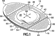
本願の開示内容の一部をなす図面の図1〜図4を参照すると、本発明の好ましい一実施形態である楕円形絆創膏14が、可撓性フィルム材料の皮膚接触層16を有し、この皮膚接触層16に、接着材料の層18が接着されている。接着材料の層18は、容易に取外し可能なライナ20によって保護されており、このライナ20は、それを横切って延びる切れ目22によって2つの別々の半部に分割され、それにより、人の皮膚への絆創膏14の貼付け中、ライナ20の半部を別々に取外すことを可能にする。変形例として、ライナ20の一方の部分は、切れ目22の箇所に沿って他方の部分の上に重なってもよく、重なり部分は、絆創膏を貼るためにライナ20を皮膚接触層16から取外すことを容易にするために、破線で示す折返し縁フラップ23を有している。一つの好ましいサイズとして、絆創膏14の長さ24は、66.67mm(2.625インチ)、その幅26は、38.1mm(1.5インチ)である。
Referring to FIGS. 1-4 of the drawings forming part of the present disclosure, an
ドーム28が、皮膚接触層16の中央に位置し且つこれに接着式に取付けられている。ドーム28は、頂部分30と円周方向側壁部分32とを有し、側壁部分32は、頂部分30と皮膚接触層16及び絆創膏14の中間部分とに相互に連結しており、これについては後で詳細に説明する。ドーム28は、薄く、強く且つ可撓性のフィルム材料のものであり、その頂部分30は、ドームの側壁部分32の高さ33によって原理的に制限されながら、中立位置から任意の方向に皮膚接触層16と平行に自由に移動する。ドームの直径29は、25.15mm(0.990インチ)であるのがよく、頂部分30の直径31は、例えば22.86mm(0.0900インチ)であり、ドーム28の高さ33は、4.76mm(0.1875インチ)であるのがよい。
A
図2〜図5に示すように、絆創膏14の好ましい実施形態では、ドーム28は、ドーム頂部層36及びドームベース層38を有している。ドームベース層38は、皮膚接触層16の第1の面、即ち、上面に固定され、例えば、ドームベース層38と同一の広がりを持つ接着材料の層40によって接着式に取付けられている。本明細書で用いるように、用語「接着式に取付けられる」は、熱融着、超音波融着及び化学的融着等の、絆創膏14の層を互いに連結する種々の機構の使用、並びに、後で詳細に説明する特に感圧接着剤等の接着材料の層の使用を含むことを理解すべきである。
As shown in FIGS. 2-5, in the preferred embodiment of the
ドーム頂部層36は、頂部分30と、側壁部分32と、スカート部分42とを有し、スカート部分42は、ほぼ平らであり、側壁部分32の基部を包囲し、この基部からすべての方向に半径方向外方に延びている。スカート部分42は、例えば接着材料の層44によって、ドームベース層38及び皮膚接触層16に接着式に取付けられている。接着材料の層44は、スカート部分42と同一の広がりを持つが、ドーム28の側壁部分32にも頂部分30にも延びていない。
The
皮膚接触層16は、ドームベース層38又はドーム頂部層36のいずれかよりも大きく、好ましくは、楕円形又はその他の細長い長円形を有し、ドーム28から互いに1対の反対方向に遠ざかるように両端部48,50まで延びている。その他の形状も、特定の場所における絆創膏14の使用に有用である。
The
ドームベース層38は、皮膚接触層16を横切る方向に横断して延び且つ互いに平行に反対側に位置する1対の直線縁部52を有し、互い反対側に位置するドームベース層38の弧状端部54は、皮膚接触層16の側縁部56の部分と一致している。同様に、ドーム頂部層36のスカート部分42は、1対の互いに平行な直線縁部58と、皮膚接触層16の側縁部56の部分と一致し且つ互いに反対側に位置する1対の弧状端部60とを有している。
The
ドーム頂部層36の直線縁部58は、ドームベース層38の互いに平行な直線縁部52の間の距離70よりも幾分大きな距離72だけ互いに離れ、その結果、各直線縁部58はそれぞれ、隣接した直線縁部52を越えて、絆創膏14の各端部の皮膚接触層16の両端部48,50のうちの近い方の端部に向かって延びている。例えば、直線縁部52間におけるドームベース層38の幅70は、好ましくは、28.6mm(1.125インチ)であって、ドーム頂部層36の幅72は、31.75mm(1.25インチ)であるのがよく、したがって、皮膚接触層16に取付けられたスカート部分42の一部が、両側で直線縁部52を越えて約1.6mm(0.0625インチ)の幅74だけドームベース層38に重なっている。かくして、接着剤層44は、ドーム頂部層36を、ドーム28を包囲する領域においてドームベース層38に取付けると共に、直線縁部52,58間の狭い領域及びドーム28と皮膚接触層16の互いに反対側に位置する端部48,50の各々との間の狭い領域において、皮膚接触層16の第1の面、即ち、上面に取付けている。スカート部分42の縁部58が縁部52を越えて重なるこの構成により、ドーム頂部層36と皮膚接触層16との連結部における絆創膏14の滑らかな輪郭が得られると共に、皮膚接触層16とのドーム28の連結部の安全性を追加する。
The
接着剤層44がドーム頂部層36のスカート部分42上にのみ存在しているので、ドームの頂部分30には、ドームベース層38には対向する上面が無い。かくして、頂部分30は、それが押される任意の方向に、それが側壁部分32の高さ33によって移動することが許される程度まで、ドームベース層38の上面と平行に且つそれに沿って移動することができる。ドーム頂部層36及びドームベース層38の薄いフィルム材料は、可撓性の強い膜であり、類似の材料の表面とこすれたときのドームの頂部分30とドームベース層38との間の摩擦が、例えば人の皮膚と靴の内面によって皮膚に押し付けられる靴下との間に生じ得る摩擦よりも著しく低くなるのに十分に小さな摩擦係数を有する。
Since the
ドーム頂部層36のフィルムは又、ガスに対して幾分透過性があるのがよく、その結果、ドーム28は、特定のドームの設計及びドーム頂部層36として用いられる特定の材料に応じて、膨らんだり、すぼまったり、潰れたりすることができる。頂部分30は、矢印66で示すように、ドームベース層38(又は、もしドームベース層38が設けられていない場合には皮膚接触層16)に接触し、且つ、それに沿って任意の方向に移動することができる。かくして、図2〜図5では、ドーム28を中立位置で示すけれども、図1では、ドーム28を潰れ位置で示し、ドーム28は、図3に破線で示すように、ベース層16の端部50に向かってオフセットされている。
The film of the
圧力又はこすれにさらされる人の皮膚の部分を、潜在的な刺激を追加しないように保護するために、絆創膏14全体は、可撓性であり、十分な強度と実用的に両立する程度に薄いことが好ましい。したがって、ドーム頂部層36は、厚さ62が約25ミクロン(1ミル)のポリエチレンフィルムのものであるのがよく、ドームベース層38も、好ましくは、厚さ64が約25ミクロン(1ミル)の同様のフィルム材料のものである。かかる薄い厚さにおいても、ポリエチレンは、十分に可撓性があり、しかも遭遇する通常の力に耐えるのに十分強い。かかる厚さの適当なポリエチレンフィルムは、ミネソタ州マンカト(Mankato)所在のクオリティー・イクストリュージョン(Quality Extrusion)からQCE5%EVA型Aポリエチレンフィルムとして入手できる。
The
好ましくは、ドームベース層38と皮膚接触層16とを相互連結する接着剤層40及びドーム頂部層36のスカート部分42とドームベース層38及び皮膚接触層16とを相互連結する接着剤層44は、約25ミクロン(1ミル)の同様の厚さ65,67を有している。適当な転写接着剤の1つは、マサチューセッツ州ノーウッド(Norwood)所在のタイコ・アドヒーシブズ(Tyco Adhesives)から“TR2295C Medical Grade Transfer Adhesive”として入手可能な、コイル状転写テープの形態をなす非感作性医療グレード生体適合性転写接着剤であり、この接着剤のウェブは、接着剤をドーム頂部層36又はドームベース層38のいずれかのポリエチレンフィルム材料とを結合させた後で比較的容易に取外し可能な裏材又はライナに支持されている。
Preferably, an
皮膚接触層16の適当な材料は、厚さ68が約50ミクロン(2ミル)のポリウレタンフィルムである。かかるポリウレタンフィルムは、適度に強くて可撓性であり、しかも、ポリエチレンよりも僅かに弾性が大きく、かくして、運動中に人の皮膚が伸びたり弛緩したりするとき、ドーム頂部層36及びドームベース層38にとって好ましいポリエチレン材料よりも皮膚に一致させることができる。
A suitable material for the
皮膚接触層16として使用するのに許容されるポリウレタンフィルムは、フィルムの一方の面に配置され且つ接着剤層18として使用できるように用意された非感作性の感圧アクリルコポリマー接着剤コーティング、及び、既に接着材料の層18に接着されたシリコーンコーティングラフト紙と一緒に、上記厚さで、ライナオハイオ州メンター(Mentor)所在のアベリー・デニソン・メディカル(Avery Dennison Medical)から入手できる。かかる積層材料は、アベリー・デニソン・メディカルからMED5042ポリウレタンフィルムとして入手できる。
An acceptable polyurethane film for use as the
かくして、使用される絆創膏14は、例えば靴の内部におけるように、嵩の追加による人の皮膚に加わる圧力の増大を回避するために、ライナ20を除いて約0.15mm(6ミル)以下の厚さを有する。
Thus, the
さらに薄い絆創膏の場合、ドーム頂部層36と皮膚接触層16との間に低摩擦係数を持つように選択された材料を用いてもよいし、ドーム頂部層36と皮膚接触層16との間に少量の適当な潤滑剤(図示せず)を含んでいてもよい。この形態では、ドームベース層38を省いてもよいけれども、この場合、皮膚接触層16に対して容易に移動するドーム28の性能、又は、ユーザに一致させる皮膚接触層16の性能のいずれかに関して妥協する必要があり得る。
For thinner bandages, a material selected to have a low coefficient of friction between the
絆創膏14は、好ましくは、絆創膏14が取付けられる皮膚からの蒸気及び水分の透過を助けるように孔あけされる。かかる孔は又、皮膚接触層の可撓性及びその延伸能力を高めることができる。孔80のアレイは、好ましくは、両端部分48,50及びスカート部分42の範囲内に設けられ、ドーム28自体に設けられてもよいし、設けられなくてもよい。孔80は、好ましくは、小さい間隔81、例えば1.27mm(0.050インチ)、好ましくは0.76〜2.28mm(0.030〜0.090インチ)だけ互いに離されている。ドーム頂部層36の直線縁部58の各々に沿って延びる領域76には、皮膚接触層16に対するドーム28の接着式取付けの安定性に対する妨害を回避するために、好ましくは、孔が設けられていない。例えば、上述の絆創膏14では、直線縁部58の各々の両側で約1.6mm(0.0625インチ)の距離78にわたって延びる領域76には、孔80がないままである。
The
絆創膏14は、ドーム28を皮膚の一部分に整列させた状態で人の皮膚に貼付けられ、上述の構成を有していなければ、かかる皮膚の一部分は、患者の皮膚と触れる物品、例えば車椅子、寝具、靴、運動用品等とこすれる場合がある。図6に示すように、ドーム28は、人の足首の外側の隆起部と整列しており、ドームの頂部分30は、スカート部分42及びその下に位置するドームベース層38に対して自由に動くことができ、皮膚接触層16は、その接着剤層18によって人の皮膚にしっかりと取付けられている。皮膚接触層16の可撓性及び弾性により、皮膚接触層16が人の足首に容易に一致し、皮膚接触層自体、人が活動するときに伸縮することを可能にする。ドーム28の頂部分30は、上述したように、ドーム28の高さによって課される制限の範囲内で、矢印66で指示するように任意の方向に自由に移動する。
The
絆創膏14又は同様の構造を有しているが寸法が異なる別の絆創膏の長さ24は、絆創膏を手の指又は足の指96等の身体の一部に貼付けるときに、皮膚接触層16の両端部分48,50が図7に示すように互いに重なることを可能にするように構成されており、これは、皮膚の破れに対する予防又は治療のために剪断力及び摩擦力を減少させることが必要な場所にドーム28が配置された状態で、絆創膏を適所にしっかりと保持するためである。
The
図8Aを参照すると、摩擦減少絆創膏、例えば絆創膏14は、好ましくは、プラスチックのフィルム又はその他の材料ウェブと作用させるための既知の生産設備を用いて、新規な工程の組合せを実施して製造される。図8Aの符号82で示す第1の工程として、転写接着材料のウェブにおいて、ドーム28の寸法及び形状と一致した開口を切取って接着剤層44を形成することによって、ドーム28が準備される。転写接着材料のウェブは、接着材料層の少なくとも一方の面に、容易に剥離する保護キャリヤシート又はライナの被覆紙を有している。いったん転写接着材料層の開口を切取ったら、転写接着材料層を、ドーム頂部層36のための1ミルのポリエチレンフィルム材料ウェブの一方の面に接着させ、符号84で指示するように、ドーム頂部層36、接着剤層44及び被覆紙キャリヤの積層体を形成する。これら最初の2つの工程は両方とも、回転コンバータ装置を用いて行われるのがよく、回転コンバータ装置は、例えば、ミネソタ州ミネアポリス所在のデルタ・インダストリーズ(Delta Industries)から入手できるCrusader(登録商標)コンバータ、又は、種々のウェブ相互間の所要の整列及び位置合わせを維持した状態で多数のウェブを個々のスプールからの多ウェブの巻出し、分離、案内、結合、再巻取りが可能な同等のコンバータ装置を用いて達成するのがよい。
Referring to FIG. 8A, a friction-reducing adhesive bandage, such as an
しかる後、符号86で注目するように、ポリエチレン又はその他のポリマーフィルムを成形するための熱及び圧力を用いて、接着剤層44を貫通する各開口内に、ドーム頂部層36のドーム28を形成する。例えば、クラムシェル包装材の製造用にかなり厚いプラスチック材料シートを形成するために通常用いられる機械を使用して、熱及び圧力の1回の付与と同時に製造される数個のドーム28を継続的に形成し、アレイをなすドーム28を形成するのがよい。加熱及び加圧サイクルの各々において27個の絆創膏14のためのドーム28及びこれらのスカート42のアレイを製造するために、ドーム頂部層36の非常に薄いポリエチレンフィルムを形成するのに適していることが判明した機械の1つは、カンザス州レネクサ(Lenexa)所在のプレコ・インダストリーズ社(Preco Industries, Inc.)から“ConvertaForm(登録商標)”形成システムとして入手できる。この機械は、自動空気圧成形システム内で適当に加熱された金型及びダイを利用し、各サイクルで約330×420mm(13インチ×16.5インチ)の成形面積を取り扱うことができる。絆創膏14に関し、かかるドームを準備するのに、最初、高さ33が0.250インチ(6.35mm)であり且つ直径31が0.900インチ(22.86mm)の平らな頂部分30を含むドームを製造するツールを用い、この頂部分30は、丸みのついた移行ゾーン92によって側壁部分32と相互連結され、移行ゾーン92の半径94は、好ましくは0.125インチであり、1.27〜3.81mm(0.050〜0.150インチ)に収まっていれば満足できる。典型的には、ドーム28の形成後、ポリエチレン材料は僅かに引込み、ドーム高さ33は、最終的には、約4.76mm(0.1875インチ)になる。かくして、ドーム28は、側壁部分32の高さ34、移行ゾーン92の範囲及びドーム頂部層36の材料の可撓性によって定められる限度の範囲内で、ドームベース層38に沿って任意の方向に自由に動くことができるようにする。
Thereafter, as noted at 86, the
頂部分30は、それが平らである代わりに、例えば、完成された絆創膏14の特性に悪影響を及ぼすことがないように、球面の一部分の形態で延びるように形成されてもよい。
Instead of being flat, the
ドーム28を、ポリエチレンのドーム頂部層36及び転写接着材料の層44の積層体の形態で形成した後、符号88に記載するように、積層体を細長く切断して、ドーム28が形成されたドーム頂部層36、接着剤層44及びそのカバーシート(図示せず)からなる積層体の連続ウェブを形成し、この連続ウェブは、直線縁部58により境界付けられ、上述した幅72を有する。
After the
次に図8Bを参照すると、符号100で示すように、上述した回転コンバータ等の回転コンバータを用いて、接着剤層40を形成するための転写接着剤層を、ドームベース層38として使用すべきフィルム材料ウェブに積層させる。符号102で示すように、ドームベース層フィルムと転写接着剤とからなる積層体を細長く切断して、所要の幅70だけ分離された直線縁部52を形成する。
Referring now to FIG. 8B, the transfer adhesive layer for forming the
図9に示すように、上述した回転コンバータ等の回転コンバータを用いて絆創膏を組み立てる。最初、符号103で示すように、皮膚接触層16に必要な材料のウェブを、絆創膏14の長さ24を包含するのに十分な幅、例えば約76mm(3インチ)の幅で細長く切る。
As shown in FIG. 9, a bandage is assembled using a rotary converter such as the rotary converter described above. Initially, as indicated at 103, the web of material required for the
次に、任意のキャリヤ又はライナを転写接着材料の層40から適当に取外すことによって、符号102で上述したように形成された層38及び層40からなるドームベース積層体を、皮膚接触層16に取付け、符号104で示すように、ドームベース層38を皮膚接触層16上に配置し、接着剤層40の作用によって皮膚接触層16に固定する。ドームベース層38は、その直線縁部52が皮膚接触層材料の細長いウェブの側面に向かってそれに面するように且つ皮膚接触層材料のウェブの長さ方向と平行になるように、皮膚接触層ウェブの中間部分に整列させられる。
Next, the dome base laminate composed of
次に、符号106で注目するように、ドーム28、スカート部分42及び接着剤層44からなる、予め形成されたドーム頂部積層体を、ドームベース層38と正確に整列させた状態で、ドーム頂部層36の直線縁部58がドームベース層の直線縁部52の外側に且つそれと平行に位置するように、ドームベース層38及び皮膚接触層36に取付ける。かくして、ドーム頂部層36のスカート部分42が、ドームベース層38と支持層16の両方に接着剤層44によって取付けられ、この状態で、ドーム頂部層36の縁部58は、ドームベース層38の直線縁部52を越えて延びている。
Next, as noted at 106, the pre-formed dome top laminate comprising the
ドーム頂部層36をドームベース層38及び皮膚接触層16に取付けた後、各絆創膏14を、好ましくはコンバータと関連した音波孔あけ機によって、適当な孔108をあける。例えば、適当な音波孔あけ機は、コネチカット州ダンベリー(Danbury)所在のブランソン・ウルトラソニック・コーポレイション(Branson Ultrasonic Corporation)から入手できる。次に、符号110で示すように、個々の絆創膏14を仕上げ寸法及び形状に切断し、好ましくは回転コンバータを用いた打抜きによって、ライナ20に切れ目22を入れる。変形例として、個々の絆創膏14を仕上げ寸法及び形状に切断する前、ライナ20を取外して、それを、一方が図1に破線で示すフラップ23としての縁折返し部を有するライナ部分の組合せに置き換えてもよい。
After attaching the
次に、絆創膏14を、皮膚接触層16、ドームベース層38及びドーム頂部層36からなる積層ウェブの周囲領域から切離し、そして、符号112で注目するように、個々の絆創膏を適当に包装する。
The
次に図10を参照すると、絆創膏114は、絆創膏14と類似した構造のものであるが、1対の拡大端部分116,118及び幅の狭いくびれ部分120を有する8の字形に似た異なる形状のものである。絆創膏114のドーム122も、1対の凸に弧状の端部分124,126を有し、これらの端部分124,126は、幅の狭いくびれ部分128によって互いに連結されている。かかる絆創膏114は、主として、人の解剖学的構造の凸状部分、例えば、ひじ、かかと、手の指及び足の指を保護するのに使用され、かかる絆創膏を、一定の範囲の寸法で製造することができ、好ましい全長130は、57mm(2.25インチ)であり、全幅132は、31.75mm(1.25インチ)であり、くびれの幅134は、22.23mm(0.875インチ)である。全長130及び全幅132は、少なくとも±1/2インチの範囲内で変化してもよい。
Referring now to FIG. 10, the
ドーム122は、絆創膏を人の皮膚にしっかりと取付けるのに十分な接着剤支持領域を皮膚接触層の端部124,126に設けるために、全長130よりも著しく短い。かくして、ドーム122の好ましい全長136は、約35mm(1.375インチ)であり、その全幅138は、約12.7mm(0.5インチ)であるが、これら寸法は両方とも、少なくとも±6.3mm(0.25インチ)の範囲内で変化してもよい。かかるドームの高さは、4〜6mm(0.18〜0.25インチ)であるのがよい。
The
次に図11を参照すると、絆創膏141が、長円形をしており、例えば、全長146が108mm(4.25インチ)であり且つ全幅148が76.2mm(3インチ)であり楕円形であり、これら両方の寸法は、±19mm(±0.75インチ)程度の大きさで変化してもよい。中央に位置する円形ドーム150が、絆創膏144の全長146及び全幅148と一致するよう設けられ、その直径は、好ましく、約57.2mm(2.25インチ)であってもよいし、それに対して±9.5mm(±3/8インチ)の範囲内で変化してもよい。絆創膏144は、ドーム150を包囲するのに十分に広いスカート部分152を有し、更に、適度に可撓性且つ弾性の皮膚接触層の或る程度の延長部を各端部分154,156に有している。上述した絆創膏14,114を比較したときの大きい方の絆創膏144は、それを圧迫潰瘍の予防及び治療に用いるのに一層適している。絆創膏144は、好ましくは、上述したフィルム材料及び接着剤等のフィルム材料と接着剤とによって作られてもよいし、異なる水分蒸気移送速度を有するフィルム材料の変形例と接着剤とによって作られてもよい。かかる絆創膏は、例えば人の仙骨(腰部)、大転子(股関節部)、大臀筋(臀部)、かかと又はひじ等の箇所に使用される。
Referring now to FIG. 11, the adhesive bandage 141 has an oval shape, for example, an
この絆創膏は、本発明から逸脱することなしに、他の特定の用途に使用すべき他の形状のドーム及び皮膚接触層を有するように製造されてもよい。 This bandage may be manufactured with other shaped domes and skin contact layers to be used for other specific applications without departing from the invention.
絆創膏14の寸法は又、患者の皮膚の領域を適当に大きい絆創膏で保護するために、同一の比率を維持したまま上述した寸法よりも例えば20%又は40%大きな寸法の絆創膏14を提供するように変化してもよい。
The size of the
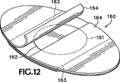
既に水疱ができた又は擦り剥いた皮膚をかかる皮膚の治癒を促進するよう治療する場合、図12に示す絆創膏160を利用するのがよい。絆創膏160は、ドームの寸法及び形状がほぼ一致し且つドーム頂部層のスカート部分の領域163及びドームベース層の領域を選択的に含む領域161において、絆創膏14にほぼ類似しているけれども、接着剤を支持する皮膚接触層の下面、即ち、第2の面が、接着剤層の無い状態のままであってもよいし、半透明で可撓性の接着剤親水コロイド材料の層162を有していてもよい。かかる親水コロイド材料は、いったんライナ164を絆創膏から取外すと、患者のただれた又は擦り剥けた皮膚又は他の創部に接触して配置され、創部からの滲出液を吸収し、湿気のある創部治癒環境を促進し、クッション材となる。かかる親水コロイド材料は、例えば、オハイオ州メンター(Mentor)所在のアベリー・デニソン・メディカル(Avery Dennison Medical)から、18ミル親水コロイド低剥離力転写接着剤テープである“MED2190H”として入手できる。これと同様な材料を、種々の用途のために10〜50ミルの範囲の種々の厚さで利用できる。
When treating already blistered or scratched skin to promote healing of such skin, a
本発明を具体化した器具は、ユーザの皮膚ではなく、器具又は衣料品の表面に貼付けられてもよい。例えば、皮膚接触層16に相当する適当な材料の層が、縫合又はその他の結合技術、即ち、熱又は超音波によって、ユーザの衣料品の内部、即ち、アンダーウェア、ソックス又は靴に取付けられてもよい。また、本発明を具体化した器具は、競技又はレクリエーション活動に使用するための肩パッド、ひじパット又はバックパックストラップに取付けられてもよい。
A device embodying the present invention may be affixed to the surface of the device or apparel rather than the user's skin. For example, a layer of suitable material corresponding to the
他の考え得る環境を取り扱うために、本発明を具体化する摩擦減少装置は、多くの物品の本来の製造中にその物品に組み込まれるのがよく、物品には、例えば、病院マットレスカバー、車椅子クッション、自転車シート、靴インサート、靴用の着脱自在なヒールカウンタ、靴の内部のその他の箇所、ソックス、下着、下着用のストラップ及びバックパックが含まれる。 In order to handle other possible environments, the friction reduction device embodying the present invention may be incorporated into the article during the original manufacture of many articles, such as hospital mattress covers, wheelchairs, etc. Includes cushions, bicycle seats, shoe inserts, removable heel counters for shoes, other parts of the shoe, socks, underwear, underwear straps and backpacks.
例えば、図13及び図14は、本発明による摩擦減少装置168を組み込んだ、スポーツ靴用の着脱自在なヒールカウンタ166を示しており、かかる摩擦減少装置168では、ドーム170が着脱自在なヒールカウンタ166の内向き面172に露出している。摩擦減少装置168は、ドーム170とドーム支持層174との間にドームベース層173を有するのがよい。ドームベース層173は、ドーム支持層174に取付けられ、ドーム170が自由に滑ることができる材料のものである。かくして、摩擦減少装置168は、ヒールカウンタ166の支持構造体中で上述したような摩擦減少絆創膏14の機能を発揮することができる構造体を有し、このヒールカウンタは、着脱自在な靴アクセサリであってもよいし、靴に固定された部分であってもよい。
For example, FIGS. 13 and 14 show a
かかる摩擦減少装置168のドーム支持層174は、図1〜図5に示す絆創膏の皮膚接触層16に相当し、厚い材料のものであるのがよく、ヒールカウンタ166自体の構造に熱的に積層されているのがよい。ドームベース層173が設けられない場合、ドーム支持層174は、ドーム頂部層170の滑り運動を邪魔しない材料のものであるべきである。絆創膏用よりも耐久性のあるものが好ましいので、ドーム支持層174は、皮膚接触層16の薄いポリウレタンフィルム材料の代わりに、より厚いフィルムのものであることが好ましく、又は、耐久性があって丈夫な織物(textile fabric)、例えば織布(woven cloth)又は編み繊維材料(knitted textile material)であってもよいし、ヒールカウンタ166の残部の隣接材料と適合性のあるポリアミド又はポリエステルのフィルム又はシート等の異なるプラスチックのものであってもよい。
The
図15及び図16に示す別の物品、例えば交換可能なアクセサリインソール180では、ドーム支持層174は、本発明の摩擦減少装置182のしっかりとした組み込みを可能にするために、摩擦減少装置182と関連した物品の構造の他の層の中に成形され又はこれらの間に挿入されるのに適したプラスチック材料、例えばポリウレタンのものであるのがよい。摩擦減少装置182も、ドーム170を有し、このドーム170は、支持層174によって支持されて、ユーザの足が接触するように露出し、ドーム28と同一の仕方で機能する。
In another article, such as the
摩擦減少ドーム170を、絆創膏14について上述した仕方とほぼ同一の仕方で製造することができ、摩擦減少装置が組み込まれる物品に応じた必要により、支持層174に修正を施してもよい。
The
図17及び図18に示すように、類似の摩擦減少装置を、スポーツ用品又は例えば上述したような他の用途の物品に含む一例として、靴188が摩擦減少装置190を有し、摩擦減少装置190の各々は、ドーム28とほぼ同一の仕方で機能する一体のドーム192を有する。摩擦減少装置190は、靴の内蔵ヒールカウンタ部分、ヒールカラー、固定インソール又は靴188の上部内の別な重要な場所に配置されるのがよい。
As shown in FIGS. 17 and 18, as an example of including a similar friction reducing device in a sporting article or other application article such as described above, a
衣料品、スポーツ用品又はその他の器具、例えば靴188に組み込まれた摩擦減少装置190の十分に長い耐久性を確保するために、ドーム頂部層194及びドームベース層196を、上述した絆創膏14のドーム頂部層36として用いられる厚さ25ミクロンのポリエチレンフィルムよりも高い強度の可撓性材料で作るのがよい。例えば、25ミクロン乃至1.525mm(1〜60mil)のより厚い厚さ198を備えたポリエチレンフィルム材料が満足のゆくものである。ポリエチレンに代えて、別のポリマー材料、例えばポリエステルフィルム又は密に織られ又は編まれた可撓性繊維材料を用いてもよいが、少量の潤滑剤をドーム頂部層194とドームベース層196との間に用いることが必要であろう。より好ましくは、頂部層194及び底部層196は、適当に形成され且つ相互連結された、靴188又はその他の物品を構成する織物、プラスチック含浸布又はプラスチックフィルムの部分であり、容易に曲がるほど十分薄く、しかも必要に応じて、互いに沿って容易に滑ることができるように潤滑されている。ドーム192を形成する材料の層の形成及び相互連結は、ドーム192を含む物品の組立て方法の一部として行われる。
In order to ensure a sufficiently long durability of the
上記説明において用いられた用語及び表現は、説明の観点で用いられていて、本発明を限定するものではなく、かかる用語及び表現の使用において、図示し、説明した特徴及びその部分の均等例を排除するものではなく、本発明の範囲は、添付の特許請求の範囲の記載に基づいてのみ定められる。 The terms and expressions used in the above description are used for the purpose of description, and are not intended to limit the present invention. In the use of such terms and expressions, the illustrated and described features and their equivalents are equivalent. It is not intended to be excluded, but the scope of the present invention will be defined only on the basis of the appended claims.
Claims (43)
互いに反対側に位置する第1の面と第2の面とを備えた可撓性フィルムの皮膚接触層と、
前記皮膚接触層の第1の面の一部分に取付けられ且つ前記一部分の上を延びる可撓性フィルムの中空ドームと、を有し、この中空ドームは、その可撓性フィルムの側壁によって少なくとも部分的に定められる高さと、頂部分とを有し、前記皮膚接触層は、前記中空ドーム全体の下に延び、前記頂部分は、前記高さと関連した距離にわたって前記皮膚接触層の第1の面に沿って自由に移動可能であり、
前記第2の面は、保護すべき表面に接着式に取付け可能である、保護用絆創膏。A protective bandage,
A skin contact layer of a flexible film having a first surface and a second surface located on opposite sides;
A flexible film hollow dome attached to and extending over a portion of the first surface of the skin contact layer, the hollow dome being at least partially by a sidewall of the flexible film. The skin contact layer extends below the entire hollow dome, and the top portion is on a first surface of the skin contact layer over a distance associated with the height. Can move freely along,
The protective adhesive bandage, wherein the second surface is attachable to the surface to be protected.
(a)可撓性フィルムを成形して、可撓性の側壁及び頂部分を有する可撓性ドームを形成し、前記可撓性ドームを、それから半径方向外方に延びる前記可撓性ドームの可撓性フィルムのほぼ平らなスカートによって包囲されるように残す工程と、
(b)しかる後、前記スカートを、可撓性フィルムのほぼ平らな皮膚接触層に接着式に取付ける工程とを有し、前記皮膚接触層は、少なくとも前記可撓性ドーム全体の下に延び、前記可撓性ドームは、潰れ可能であり、前記頂部分は、前記皮膚接触層に沿って移動可能である、製造方法。A method of manufacturing a bandage,
(A) forming a flexible film to form a flexible dome having flexible sidewalls and a top portion, the flexible dome extending radially outward therefrom; Leaving it surrounded by a substantially flat skirt of flexible film;
(B) thereafter, adhesively attaching the skirt to a substantially flat skin contact layer of a flexible film, the skin contact layer extending at least under the entire flexible dome; The method of manufacturing, wherein the flexible dome is collapsible and the top portion is movable along the skin contact layer.
前記スカートを前記皮膚接触層に取付ける工程は、前記スカートの一部分を前記ドームベース層に接着式に取付ける工程を含む、請求項27記載の方法。Prior to the step of attaching the skirt to the skin contact layer, a substantially flat dome base layer of flexible film is adhesively attached to the skin contact layer and at least in place extending under the entire flexible dome. Having a process,
28. The method of claim 27, wherein the step of attaching the skirt to the skin contact layer comprises the step of adhesively attaching a portion of the skirt to the dome base layer.
(a)互いに反対側に位置する第1の面と第2の面とを有する可撓性材料の支持層と、
(b)前記支持層の第1の面の一部分に取付けられ且つその一部分を覆って延びる可撓性材料の中空ドームと、を有し、前記中空ドームは、高さ及び頂部分を有し、前記頂部分は、前記高さと関連した距離にわたって前記支持層の第1の面に沿って自由に移動可能であり、
(c)前記第2の面は、保護すべき表面に前記中空ドームを露出させるように前記靴の一部に取付けられる、靴。 A shoe having a friction reducing device, the friction reducing device comprising:
(A) a support layer of flexible material having a first surface and a second surface located on opposite sides;
(B) a hollow dome of flexible material attached to and extending over a portion of the first surface of the support layer, the hollow dome having a height and a top portion; The top portion is freely movable along the first surface of the support layer over a distance associated with the height;
(C) the second surface is attached to a portion of the shoe to expose the hollow dome surface to be protected, the shoe.
(a)互いに反対側に位置する第1の面と第2の面とを有する可撓性材料の支持層と、
(b)前記支持層の第1の面の一部分に取付けられ且つその一部分を覆って延びる可撓性材料の中空ドームと、を有し、前記中空ドームは、高さ及び頂部分を有し、前記頂部分は、前記高さと関連した距離にわたって前記支持層の第1の面に沿って自由に移動可能であり、
(c)前記ヒールカラーの使用中、前記第2の面は、保護すべき表面に前記中空ドームを露出させるように前記ヒールカラーの一部に取付けられる、ヒールカラー。 A removable heel collar for shoes, the heel collar having a friction reducing device, the friction reducing device comprising:
(A) a support layer of flexible material having a first surface and a second surface located on opposite sides;
(B) a hollow dome of flexible material attached to and extending over a portion of the first surface of the support layer, the hollow dome having a height and a top portion; The top portion is freely movable along the first surface of the support layer over a distance associated with the height;
(C) A heel collar, wherein the second surface is attached to a portion of the heel collar so that the hollow dome is exposed on the surface to be protected during use of the heel collar .
(a)互いに反対側に位置する第1の面と第2の面とを有する可撓性材料の支持層と、
(b)前記支持層の第1の面の一部分に取付けられ且つその一部分を覆って延びる可撓性材料の中空ドームと、を有し、前記中空ドームは、高さ及び頂部分を有し、前記頂部分は、前記高さと関連した距離にわたって前記支持層の第1の面に沿って自由に移動可能であり、
(c)前記ヒールカウンタの使用中、前記第2の面は、保護すべき表面に前記中空ドームを露出させるように前記ヒールカウンタの一部に取付けられる、ヒールカウンタ。A removable heel counter for shoes , the heel counter having a friction reducing device, the friction reducing device comprising:
(A) a support layer of flexible material having a first surface and a second surface located on opposite sides;
(B) a hollow dome of flexible material attached to and extending over a portion of the first surface of the support layer, the hollow dome having a height and a top portion; The top portion is freely movable along the first surface of the support layer over a distance associated with the height;
During use of (c) the heel counter, the second surface is attached to a portion of the heel counter to expose the hollow dome surface to be protected, the heel counter.
(a)互いに反対側に位置する第1の面と第2の面とを有する可撓性材料の支持層と、(A) a support layer of flexible material having a first surface and a second surface located on opposite sides;
(b)前記支持層の第1の面の一部分に取付けられ且つその一部分を覆って延びる可撓性材料の中空ドームと、を有し、前記中空ドームは、高さ及び頂部分を有し、前記頂部分は、前記高さと関連した距離にわたって前記支持層の第1の面に沿って自由に移動可能であり、(B) a hollow dome of flexible material attached to and extending over a portion of the first surface of the support layer, the hollow dome having a height and a top portion; The top portion is freely movable along the first surface of the support layer over a distance associated with the height;
(c)前記インソールの使用中、前記第2の面は、保護すべき表面に前記中空ドームを露出させるように前記インソールの一部に取付けられる、インソール。(C) during use of the insole, the second surface is attached to a portion of the insole such that the hollow dome is exposed on the surface to be protected.
(a)可撓性フィルムを成形して、可撓性の側壁及び頂部分を有する可撓性ドームを形成し、前記可撓性ドームを、それから半径方向外方に延び且つ前記可撓性ドームを構成する可撓性フィルムのほぼ平らなスカートによって包囲されるように残す工程と、
(b)しかる後、前記スカートを、少なくとも前記可撓性ドーム全体の下に延びるように可撓性フィルムの皮膚接触層に接着式に取付ける工程と、前記皮膚接触層と前記可撓性ドームの頂部分との間の前記側壁を、それが自由に曲がるように残し、それにより、前記可撓性ドームを潰れ可能に残し、前記頂部分を、それが前記側壁によって制限される程度まで前記皮膚接触層に沿って移動可能であるように残す工程と、を有する製造方法。A method of manufacturing a bandage,
(A) forming a flexible film to form a flexible dome having flexible sidewalls and a top portion, the flexible dome extending radially outward therefrom and the flexible dome; Leaving to be surrounded by a substantially flat skirt of flexible film comprising
(B) thereafter, adhesively attaching the skirt to the skin contact layer of the flexible film so as to extend at least under the entire flexible dome; and the skin contact layer and the flexible dome. Leaving the side wall between the top part so that it bends freely, thereby leaving the flexible dome collapsible and leaving the top part to the extent that it is limited by the side wall. And leaving it so as to be movable along the contact layer.
前記スカートを前記皮膚接触層に取付ける工程は、前記可撓性ドームを前記ドームベース層の上に配置する工程と、前記スカートの一部分を前記ドームベース層に接着式に取付ける工程と、前記側壁が自由に曲がるまま残し、それにより、前記頂部分が前記ドームベース層に沿って自由に移動したまま残す工程とを含む、請求項41記載の方法。Before the step of attaching the skirt to the skin contact layer, further comprising the step of adhesively attaching a dome base layer of a flexible film to the skin contact layer;
Attaching the skirt to the skin contact layer includes placing the flexible dome over the dome base layer, attaching a portion of the skirt to the dome base layer adhesively, and the sidewalls 42. The method of claim 41 , comprising leaving the bend freely and thereby leaving the top portion free moving along the dome base layer.
Applications Claiming Priority (3)
| Application Number | Priority Date | Filing Date | Title |
|---|---|---|---|
| US10/637,429 US20050033211A1 (en) | 2003-08-08 | 2003-08-08 | Friction reducing bandage |
| US10/672,731 US7087806B2 (en) | 2003-08-08 | 2003-09-25 | Friction reducing devices |
| PCT/US2004/025108 WO2005016179A2 (en) | 2003-08-08 | 2004-08-03 | Friction reducing devices |
Publications (3)
| Publication Number | Publication Date |
|---|---|
| JP2007501672A JP2007501672A (en) | 2007-02-01 |
| JP2007501672A5 JP2007501672A5 (en) | 2007-09-20 |
| JP4611980B2 true JP4611980B2 (en) | 2011-01-12 |
Family
ID=34198359
Family Applications (1)
| Application Number | Title | Priority Date | Filing Date |
|---|---|---|---|
| JP2006523227A Expired - Fee Related JP4611980B2 (en) | 2003-08-08 | 2004-08-03 | Friction reduction device |
Country Status (4)
| Country | Link |
|---|---|
| US (1) | US7479577B2 (en) |
| EP (1) | EP1660000B1 (en) |
| JP (1) | JP4611980B2 (en) |
| WO (1) | WO2005016179A2 (en) |
Families Citing this family (49)
| Publication number | Priority date | Publication date | Assignee | Title |
|---|---|---|---|---|
| CA2385826C (en) * | 2002-05-10 | 2003-12-02 | Earth Angel Inc. | Cap for attachment to a barrel end and storage means therefor |
| GB0224986D0 (en) | 2002-10-28 | 2002-12-04 | Smith & Nephew | Apparatus |
| US11298453B2 (en) | 2003-10-28 | 2022-04-12 | Smith & Nephew Plc | Apparatus and method for wound cleansing with actives |
| GB0325129D0 (en) | 2003-10-28 | 2003-12-03 | Smith & Nephew | Apparatus in situ |
| US8062272B2 (en) | 2004-05-21 | 2011-11-22 | Bluesky Medical Group Incorporated | Flexible reduced pressure treatment appliance |
| US7909805B2 (en) | 2004-04-05 | 2011-03-22 | Bluesky Medical Group Incorporated | Flexible reduced pressure treatment appliance |
| US10058642B2 (en) | 2004-04-05 | 2018-08-28 | Bluesky Medical Group Incorporated | Reduced pressure treatment system |
| US7753894B2 (en) | 2004-04-27 | 2010-07-13 | Smith & Nephew Plc | Wound cleansing apparatus with stress |
| GB0409446D0 (en) | 2004-04-28 | 2004-06-02 | Smith & Nephew | Apparatus |
| GB0508531D0 (en) | 2005-04-27 | 2005-06-01 | Smith & Nephew | Sai with ultrasound |
| CA2872297C (en) | 2006-09-28 | 2016-10-11 | Smith & Nephew, Inc. | Portable wound therapy system |
| GB0722820D0 (en) | 2007-11-21 | 2008-01-02 | Smith & Nephew | Vacuum assisted wound dressing |
| EP2214612B1 (en) | 2007-11-21 | 2019-05-01 | Smith & Nephew PLC | Wound dressing |
| CN101868203B (en) | 2007-11-21 | 2014-10-22 | 史密夫及内修公开有限公司 | Wound dressing |
| GB0723872D0 (en) | 2007-12-06 | 2008-01-16 | Smith & Nephew | Apparatus for topical negative pressure therapy |
| US8021347B2 (en) | 2008-07-21 | 2011-09-20 | Tyco Healthcare Group Lp | Thin film wound dressing |
| US9033942B2 (en) | 2008-03-07 | 2015-05-19 | Smith & Nephew, Inc. | Wound dressing port and associated wound dressing |
| US8298200B2 (en) | 2009-06-01 | 2012-10-30 | Tyco Healthcare Group Lp | System for providing continual drainage in negative pressure wound therapy |
| CA2731427C (en) | 2008-08-08 | 2020-01-28 | Tyco Healthcare Group Lp | Wound dressing of continuous fibers |
| EP2347788A4 (en) * | 2008-11-17 | 2012-05-16 | Yoichi Inaba | Simple device for treating trichophytosis unguium |
| US8162907B2 (en) | 2009-01-20 | 2012-04-24 | Tyco Healthcare Group Lp | Method and apparatus for bridging from a dressing in negative pressure wound therapy |
| GB0905290D0 (en) * | 2009-03-27 | 2009-05-13 | First Water Ltd | Multilayer compositions and dressings |
| US20100324516A1 (en) | 2009-06-18 | 2010-12-23 | Tyco Healthcare Group Lp | Apparatus for Vacuum Bridging and/or Exudate Collection |
| WO2011087871A2 (en) | 2009-12-22 | 2011-07-21 | Smith & Nephew, Inc. | Apparatuses and methods for negative pressure wound therapy |
| US9061095B2 (en) | 2010-04-27 | 2015-06-23 | Smith & Nephew Plc | Wound dressing and method of use |
| USRE48117E1 (en) | 2010-05-07 | 2020-07-28 | Smith & Nephew, Inc. | Apparatuses and methods for negative pressure wound therapy |
| LT2648668T (en) * | 2010-12-08 | 2018-08-10 | Convatec Technologies Inc. | Self-sealing dressing |
| USD714433S1 (en) | 2010-12-22 | 2014-09-30 | Smith & Nephew, Inc. | Suction adapter |
| WO2012087376A1 (en) | 2010-12-22 | 2012-06-28 | Smith & Nephew, Inc. | Apparatuses and methods for negative pressure wound therapy |
| US20120238971A1 (en) * | 2011-01-18 | 2012-09-20 | Omnitek Partners Llc | Shape and Pressure Adjustable Dressing For Blisters and Puncture Wounds |
| US9125787B2 (en) | 2011-09-30 | 2015-09-08 | Covidien Lp | Compression garment having a foam layer |
| US20170156812A1 (en) * | 2012-03-20 | 2017-06-08 | Carpal Aid, Llc | Therapeutic skin lifting device and related systems and methods |
| KR101538650B1 (en) | 2012-03-20 | 2015-07-22 | 카펄 에이드, 엘엘씨 | Therapeutic skin lifting device and related systems and methods |
| EP3650055A1 (en) | 2012-05-23 | 2020-05-13 | Smith & Nephew plc | Apparatuses and methods for negative pressure wound therapy |
| DK2879636T3 (en) | 2012-08-01 | 2017-06-19 | Smith & Nephew | Wound dressing |
| EP2879635A2 (en) | 2012-08-01 | 2015-06-10 | Smith & Nephew PLC | Wound dressing and method of treatment |
| US9402779B2 (en) | 2013-03-11 | 2016-08-02 | Covidien Lp | Compression garment with perspiration relief |
| AU2014266943B2 (en) | 2013-05-10 | 2018-03-01 | Smith & Nephew Plc | Fluidic connector for irrigation and aspiration of wounds |
| WO2016040695A1 (en) * | 2014-09-10 | 2016-03-17 | C.R. Bard, Inc. | Protective dressing for skin-placed medical device |
| US10456300B2 (en) * | 2014-12-04 | 2019-10-29 | Benjamin Schiff | Ring compression bandage |
| US10076594B2 (en) | 2015-05-18 | 2018-09-18 | Smith & Nephew Plc | Fluidic connector for negative pressure wound therapy |
| US9326504B1 (en) | 2015-06-23 | 2016-05-03 | Christine Graziano | Disposable antibacterial liner |
| JP6053878B1 (en) * | 2015-06-26 | 2016-12-27 | キヤノン株式会社 | Information processing apparatus and control method thereof, portable terminal and control method thereof, service providing system and program |
| WO2018100327A1 (en) * | 2016-12-02 | 2018-06-07 | Waters Leonard Vincent | Shear force negating plaster |
| USD816833S1 (en) | 2017-01-10 | 2018-05-01 | Tidi Products, Llc | Access needle securement device |
| GB201718014D0 (en) | 2017-11-01 | 2017-12-13 | Smith & Nephew | Dressing for negative pressure wound therapy with filter |
| GB201811449D0 (en) | 2018-07-12 | 2018-08-29 | Smith & Nephew | Apparatuses and methods for negative pressure wound therapy |
| USD952163S1 (en) | 2021-02-09 | 2022-05-17 | Coloplast A/S | Wound dressing |
| USD962449S1 (en) | 2021-02-09 | 2022-08-30 | Coloplast A/S | Wound dressing |
Family Cites Families (35)
| Publication number | Priority date | Publication date | Assignee | Title |
|---|---|---|---|---|
| US1913928A (en) | 1926-10-27 | 1933-06-13 | Morris P Kaufman | Means for treating and protecting corns |
| US2098312A (en) | 1935-11-11 | 1937-11-09 | William M Scholl | Foot pad |
| US2261041A (en) | 1939-10-02 | 1941-10-28 | Ross A Tennant | Orthopedic device |
| US2669989A (en) | 1947-04-02 | 1954-02-23 | Shoucair Edward | Friction reducing device |
| US2712311A (en) | 1950-09-09 | 1955-07-05 | William M Scholl | Molded foam latex surgical pad and method of making same |
| US2817335A (en) | 1955-06-10 | 1957-12-24 | Thalmer J Thompson | Bandage and dressing |
| US2918062A (en) | 1958-07-30 | 1959-12-22 | William M Scholl | Medicinal plaster or bandage |
| US3062208A (en) | 1959-11-12 | 1962-11-06 | William M Scholl | Surgical pad |
| US3260261A (en) | 1964-03-23 | 1966-07-12 | Matilda L Gallovich | Anti-chafing device and method |
| US3548420A (en) | 1967-03-06 | 1970-12-22 | Stryker Corp | Cushion structure |
| US3821954A (en) | 1971-04-16 | 1974-07-02 | H Grubel | Dressing with quantity of particulate material |
| GB1454292A (en) | 1973-02-24 | 1976-11-03 | Searle & Co | Body support means |
| USRE33727E (en) | 1980-09-11 | 1991-10-29 | Baxter International, Inc. | Bandage frame |
| CA1192825A (en) | 1980-11-10 | 1985-09-03 | Minnesota Mining And Manufacturing Company | Device and method for applying conformable, thin adhesive-coated films |
| JPS5819201A (en) * | 1981-07-20 | 1983-02-04 | スベンスカ・トバクス・アクテイエボラ−グ | Insole for footwear |
| US4572174A (en) | 1983-11-22 | 1986-02-25 | Kasriel Eilender | Low friction bed pad |
| US4600001A (en) | 1984-08-15 | 1986-07-15 | The Kendall Company | Combined wound dressing and delivery means composite |
| JPS6191214U (en) * | 1984-11-21 | 1986-06-13 | ||
| US4729369A (en) | 1986-06-20 | 1988-03-08 | Cook Donald E | Toe splint and bunion correction device |
| US4959059A (en) | 1989-01-17 | 1990-09-25 | Senecare Enterprises, Inc. | Low friction multilayer pad |
| US5188124A (en) | 1989-07-19 | 1993-02-23 | Johnson & Johnson Consumer Products, Inc. | Low friction film dressing |
| US5012801A (en) | 1989-07-19 | 1991-05-07 | Johnson & Johnson Consumer Products, Inc. | Low friction film dressing |
| US5170781A (en) | 1991-11-15 | 1992-12-15 | Loomis Dawn L | Protective bandage having improved impact protection |
| EP0690706B1 (en) | 1993-03-22 | 2000-11-02 | Minnesota Mining And Manufacturing Company | Windowless frame delivered dressing and method of manufacture |
| US5364339A (en) | 1993-04-07 | 1994-11-15 | Juanita Carver | Bed sore pad |
| US5590420A (en) * | 1994-03-24 | 1997-01-07 | Gunn; Robert T. | Low friction apparel |
| US5512041A (en) * | 1994-10-07 | 1996-04-30 | Scott Health Care | Wound dressing for promoting moist wound healing |
| US6093160A (en) * | 1994-11-21 | 2000-07-25 | Augustine Medical, Inc. | Flexible non-contact wound treatment device |
| US5580346A (en) * | 1995-02-17 | 1996-12-03 | Spier; I. Martin | Protective covering for body lesions |
| US5665060A (en) | 1995-12-15 | 1997-09-09 | Dr. Fabricant's Foot Health Products, Inc. | Bunion treatment apparatus and method |
| US5899207A (en) * | 1998-03-16 | 1999-05-04 | The Seaberg Company, Inc. | Protecting skin from friction |
| US6143945A (en) | 1998-04-06 | 2000-11-07 | Augustine Medical, Inc. | Bandage for autolytic wound debridement |
| US6362387B1 (en) * | 1998-06-15 | 2002-03-26 | Tamarack Habilitation Technologies, Inc. | Self-adhering friction reducing liner and method of use |
| US6916967B2 (en) * | 2003-07-09 | 2005-07-12 | Venture Tape Corp. | Adhesive bandage for protection of skin surfaces |
| US20050033211A1 (en) | 2003-08-08 | 2005-02-10 | Samuel Scheinberg | Friction reducing bandage |
-
2004
- 2004-08-03 WO PCT/US2004/025108 patent/WO2005016179A2/en active Application Filing
- 2004-08-03 JP JP2006523227A patent/JP4611980B2/en not_active Expired - Fee Related
- 2004-08-03 EP EP04780016A patent/EP1660000B1/en active Active
-
2006
- 2006-08-08 US US11/501,670 patent/US7479577B2/en not_active Expired - Lifetime
Also Published As
| Publication number | Publication date |
|---|---|
| US20070027423A1 (en) | 2007-02-01 |
| WO2005016179A3 (en) | 2005-08-18 |
| US7479577B2 (en) | 2009-01-20 |
| EP1660000A4 (en) | 2011-05-25 |
| JP2007501672A (en) | 2007-02-01 |
| EP1660000A2 (en) | 2006-05-31 |
| EP1660000B1 (en) | 2012-10-10 |
| WO2005016179A2 (en) | 2005-02-24 |
Similar Documents
| Publication | Publication Date | Title |
|---|---|---|
| JP4611980B2 (en) | Friction reduction device | |
| US7087806B2 (en) | Friction reducing devices | |
| EP2440167B1 (en) | Customizable therapeutic compression garment and method | |
| CN101431969B (en) | An adhesive wafer | |
| KR101158571B1 (en) | Finger/toe tip protective apparatus | |
| WO2006099405A2 (en) | Bandage with splint | |
| JP6945114B2 (en) | socks | |
| JPH0724008A (en) | Absorptive article with clasp and method for bonding the absorptive article to adjacent garment | |
| EP3344207A1 (en) | Contact point reduction garment | |
| JP7352701B2 (en) | foot cover | |
| JP6034521B1 (en) | Water absorbent bandage and water absorbent bandage group for toes | |
| JP2003183902A (en) | Shorts for fitting absorbent article | |
| US20210393444A1 (en) | Friction reducing devices and orthopedic foot inserts | |
| JP4804758B2 (en) | Molded ankle splint | |
| JP3939068B2 (en) | Patch with fastener | |
| JP3086861U (en) | Adhesive tape for knee joint fixation | |
| KR200461059Y1 (en) | Sack treat beauty or disease limb | |
| JP2019170627A (en) | Sweat absorbing pad for armpit | |
| JP2001258925A (en) | Strap formed with s-shaped cut and petal style elliptical strap |
Legal Events
| Date | Code | Title | Description |
|---|---|---|---|
| A521 | Request for written amendment filed |
Free format text: JAPANESE INTERMEDIATE CODE: A523 Effective date: 20070801 |
|
| A621 | Written request for application examination |
Free format text: JAPANESE INTERMEDIATE CODE: A621 Effective date: 20070801 |
|
| A711 | Notification of change in applicant |
Free format text: JAPANESE INTERMEDIATE CODE: A711 Effective date: 20091005 |
|
| A521 | Request for written amendment filed |
Free format text: JAPANESE INTERMEDIATE CODE: A821 Effective date: 20091005 |
|
| A131 | Notification of reasons for refusal |
Free format text: JAPANESE INTERMEDIATE CODE: A131 Effective date: 20100531 |
|
| A521 | Request for written amendment filed |
Free format text: JAPANESE INTERMEDIATE CODE: A523 Effective date: 20100826 |
|
| TRDD | Decision of grant or rejection written | ||
| A01 | Written decision to grant a patent or to grant a registration (utility model) |
Free format text: JAPANESE INTERMEDIATE CODE: A01 Effective date: 20100921 |
|
| A01 | Written decision to grant a patent or to grant a registration (utility model) |
Free format text: JAPANESE INTERMEDIATE CODE: A01 |
|
| A61 | First payment of annual fees (during grant procedure) |
Free format text: JAPANESE INTERMEDIATE CODE: A61 Effective date: 20101014 |
|
| FPAY | Renewal fee payment (event date is renewal date of database) |
Free format text: PAYMENT UNTIL: 20131022 Year of fee payment: 3 |
|
| R150 | Certificate of patent or registration of utility model |
Ref document number: 4611980 Country of ref document: JP Free format text: JAPANESE INTERMEDIATE CODE: R150 Free format text: JAPANESE INTERMEDIATE CODE: R150 |
|
| R250 | Receipt of annual fees |
Free format text: JAPANESE INTERMEDIATE CODE: R250 |
|
| R250 | Receipt of annual fees |
Free format text: JAPANESE INTERMEDIATE CODE: R250 |
|
| R250 | Receipt of annual fees |
Free format text: JAPANESE INTERMEDIATE CODE: R250 |
|
| R250 | Receipt of annual fees |
Free format text: JAPANESE INTERMEDIATE CODE: R250 |
|
| R250 | Receipt of annual fees |
Free format text: JAPANESE INTERMEDIATE CODE: R250 |
|
| R250 | Receipt of annual fees |
Free format text: JAPANESE INTERMEDIATE CODE: R250 |
|
| LAPS | Cancellation because of no payment of annual fees |