EP3404485B1 - A lithographic reticle system - Google Patents
A lithographic reticle system Download PDFInfo
- Publication number
- EP3404485B1 EP3404485B1 EP17171170.8A EP17171170A EP3404485B1 EP 3404485 B1 EP3404485 B1 EP 3404485B1 EP 17171170 A EP17171170 A EP 17171170A EP 3404485 B1 EP3404485 B1 EP 3404485B1
- Authority
- EP
- European Patent Office
- Prior art keywords
- pellicle
- reticle
- membrane
- pellicle membrane
- frame
- Prior art date
- Legal status (The legal status is an assumption and is not a legal conclusion. Google has not performed a legal analysis and makes no representation as to the accuracy of the status listed.)
- Active
Links
Images

Classifications
-
- G—PHYSICS
- G03—PHOTOGRAPHY; CINEMATOGRAPHY; ANALOGOUS TECHNIQUES USING WAVES OTHER THAN OPTICAL WAVES; ELECTROGRAPHY; HOLOGRAPHY
- G03F—PHOTOMECHANICAL PRODUCTION OF TEXTURED OR PATTERNED SURFACES, e.g. FOR PRINTING, FOR PROCESSING OF SEMICONDUCTOR DEVICES; MATERIALS THEREFOR; ORIGINALS THEREFOR; APPARATUS SPECIALLY ADAPTED THEREFOR
- G03F1/00—Originals for photomechanical production of textured or patterned surfaces, e.g., masks, photo-masks, reticles; Mask blanks or pellicles therefor; Containers specially adapted therefor; Preparation thereof
- G03F1/62—Pellicles, e.g. pellicle assemblies, e.g. having membrane on support frame; Preparation thereof
- G03F1/64—Pellicles, e.g. pellicle assemblies, e.g. having membrane on support frame; Preparation thereof characterised by the frames, e.g. structure or material, including bonding means therefor
-
- G—PHYSICS
- G03—PHOTOGRAPHY; CINEMATOGRAPHY; ANALOGOUS TECHNIQUES USING WAVES OTHER THAN OPTICAL WAVES; ELECTROGRAPHY; HOLOGRAPHY
- G03F—PHOTOMECHANICAL PRODUCTION OF TEXTURED OR PATTERNED SURFACES, e.g. FOR PRINTING, FOR PROCESSING OF SEMICONDUCTOR DEVICES; MATERIALS THEREFOR; ORIGINALS THEREFOR; APPARATUS SPECIALLY ADAPTED THEREFOR
- G03F1/00—Originals for photomechanical production of textured or patterned surfaces, e.g., masks, photo-masks, reticles; Mask blanks or pellicles therefor; Containers specially adapted therefor; Preparation thereof
- G03F1/62—Pellicles, e.g. pellicle assemblies, e.g. having membrane on support frame; Preparation thereof
-
- G—PHYSICS
- G03—PHOTOGRAPHY; CINEMATOGRAPHY; ANALOGOUS TECHNIQUES USING WAVES OTHER THAN OPTICAL WAVES; ELECTROGRAPHY; HOLOGRAPHY
- G03F—PHOTOMECHANICAL PRODUCTION OF TEXTURED OR PATTERNED SURFACES, e.g. FOR PRINTING, FOR PROCESSING OF SEMICONDUCTOR DEVICES; MATERIALS THEREFOR; ORIGINALS THEREFOR; APPARATUS SPECIALLY ADAPTED THEREFOR
- G03F7/00—Photomechanical, e.g. photolithographic, production of textured or patterned surfaces, e.g. printing surfaces; Materials therefor, e.g. comprising photoresists; Apparatus specially adapted therefor
- G03F7/70—Microphotolithographic exposure; Apparatus therefor
- G03F7/70691—Handling of masks or workpieces
- G03F7/70733—Handling masks and workpieces, e.g. exchange of workpiece or mask, transport of workpiece or mask
-
- G—PHYSICS
- G03—PHOTOGRAPHY; CINEMATOGRAPHY; ANALOGOUS TECHNIQUES USING WAVES OTHER THAN OPTICAL WAVES; ELECTROGRAPHY; HOLOGRAPHY
- G03F—PHOTOMECHANICAL PRODUCTION OF TEXTURED OR PATTERNED SURFACES, e.g. FOR PRINTING, FOR PROCESSING OF SEMICONDUCTOR DEVICES; MATERIALS THEREFOR; ORIGINALS THEREFOR; APPARATUS SPECIALLY ADAPTED THEREFOR
- G03F7/00—Photomechanical, e.g. photolithographic, production of textured or patterned surfaces, e.g. printing surfaces; Materials therefor, e.g. comprising photoresists; Apparatus specially adapted therefor
- G03F7/70—Microphotolithographic exposure; Apparatus therefor
- G03F7/708—Construction of apparatus, e.g. environment aspects, hygiene aspects or materials
- G03F7/70808—Construction details, e.g. housing, load-lock, seals or windows for passing light in or out of apparatus
- G03F7/70825—Mounting of individual elements, e.g. mounts, holders or supports
-
- G—PHYSICS
- G03—PHOTOGRAPHY; CINEMATOGRAPHY; ANALOGOUS TECHNIQUES USING WAVES OTHER THAN OPTICAL WAVES; ELECTROGRAPHY; HOLOGRAPHY
- G03F—PHOTOMECHANICAL PRODUCTION OF TEXTURED OR PATTERNED SURFACES, e.g. FOR PRINTING, FOR PROCESSING OF SEMICONDUCTOR DEVICES; MATERIALS THEREFOR; ORIGINALS THEREFOR; APPARATUS SPECIALLY ADAPTED THEREFOR
- G03F7/00—Photomechanical, e.g. photolithographic, production of textured or patterned surfaces, e.g. printing surfaces; Materials therefor, e.g. comprising photoresists; Apparatus specially adapted therefor
- G03F7/70—Microphotolithographic exposure; Apparatus therefor
- G03F7/708—Construction of apparatus, e.g. environment aspects, hygiene aspects or materials
- G03F7/70975—Assembly, maintenance, transport or storage of apparatus
-
- G—PHYSICS
- G03—PHOTOGRAPHY; CINEMATOGRAPHY; ANALOGOUS TECHNIQUES USING WAVES OTHER THAN OPTICAL WAVES; ELECTROGRAPHY; HOLOGRAPHY
- G03F—PHOTOMECHANICAL PRODUCTION OF TEXTURED OR PATTERNED SURFACES, e.g. FOR PRINTING, FOR PROCESSING OF SEMICONDUCTOR DEVICES; MATERIALS THEREFOR; ORIGINALS THEREFOR; APPARATUS SPECIALLY ADAPTED THEREFOR
- G03F7/00—Photomechanical, e.g. photolithographic, production of textured or patterned surfaces, e.g. printing surfaces; Materials therefor, e.g. comprising photoresists; Apparatus specially adapted therefor
- G03F7/70—Microphotolithographic exposure; Apparatus therefor
- G03F7/708—Construction of apparatus, e.g. environment aspects, hygiene aspects or materials
- G03F7/70983—Optical system protection, e.g. pellicles or removable covers for protection of mask
Landscapes
- Physics & Mathematics (AREA)
- General Physics & Mathematics (AREA)
- Health & Medical Sciences (AREA)
- Engineering & Computer Science (AREA)
- Environmental & Geological Engineering (AREA)
- Epidemiology (AREA)
- Public Health (AREA)
- Preparing Plates And Mask In Photomechanical Process (AREA)
- Exposure And Positioning Against Photoresist Photosensitive Materials (AREA)
Description
- The present inventive concept relates to a lithographic reticle system, a lithographic exposure tool and methods for exchanging a pellicle membrane of a lithographic exposure tool.
- In semiconductor fabrication, various lithographic processes are extensively used in the course of defining devices and circuit patterns. Depending on the size of the features to be defined, different optical lithographic processes may be used. In a lithographic process, a pattern present on a photomask or reticle may be transferred to a light-sensitive photoresist coating by illuminating the reticle. The light is modulated by the reticle pattern and imaged onto a photoresist-coated wafer.
- In conventional lithography, a pellicle is commonly placed on the reticle to protect the reticle from contamination during handling and exposure etcetera. The pellicle will thus protect the reticle from unwanted particles which otherwise could negatively impact the fidelity of the pattern transfer to the wafer. As the pellicle remains covers the reticle during exposure, there are stringent requirements on the pellicle in terms of absorption, durability and particle shielding capabilities etcetera.
- The membrane of the pellicle may however, due to the radiation and/or chemicals in the process environment, degrade over time. Some degradation may be acceptable but eventually the reticle and the pellicle need to be removed from the lithographic exposure tool to allow replacement of the pellicle. The reticle and the pellicle are typically returned to a mask shop where the pellicle replacement may be performed. This may cause undesired interruptions in the fabrication process. Moreover, while the pellicle is being replaced the reticle surface is exposed to the ambient atmosphere and particles existing in the environment.
- An objective of the present inventive concept is to address the above-mentioned issues. Further objectives may be understood from the following.
- According to a first aspect of the present inventive concept there is provided a lithographic reticle system comprising:
- a reticle,
- a first pellicle membrane mounted in front of the reticle, and
- a second pellicle membrane mounted in front of the first pellicle membrane,
- wherein the first pellicle membrane is arranged between the reticle and the second pellicle membrane, and
- wherein the second pellicle membrane is releasably mounted in relation to the first pellicle membrane and the reticle.
- By the inventive lithographic reticle system, there is provided a dual-pellicle membrane wherein the second pellicle membrane, by being releasably mounted in front of and in relation to the first pellicle membrane and the reticle, may be conveniently replaced when needed.
- By the second pellicle membrane being "releasably mounted in relation to the first pellicle membrane and the reticle" is hereby meant that the second pellicle membrane is mounted such that removal of the second pellicle membrane is allowed while the first pellicle membrane remains mounted in front of the reticle. The first pellicle membrane may accordingly shield or protect the reticle while the second pellicle membrane is being replaced.
- Since the first pellicle membrane is arranged between the reticle and the second pellicle membrane, the first pellicle membrane may be shielded from the process environment by the second pellicle membrane.
- The above-stated advantages may obviate or at least reduce the need for returning the reticle to the mask shop for pellicle replacement.
- Moreover, as will be further described below, the releasable arrangement of the second pellicle membrane may enable in-situ replacement of the second pellicle membrane, i.e. inside the lithography tool.
- Although pellicle degradation and replacement is an issue in the field of lithography at large. It may, as realized by the inventors, become an increasing issue in extreme ultraviolet lithography, EUVL, where the short wavelength, high power and the potentially adverse process conditions (for instance due to a hydrogen atmosphere in the reticle chamber environment) may accelerate the degradation of a pellicle membrane. The advantages of the inventive lithographic reticle system may hence be particularly pronounced in connection with EUVL.
- The reticle may be arranged on a reticle support. By "reticle support" is hereby meant a base or a support arranged to act as a support for the reticle in a lithographic exposure tool. The reticle support may be configured to allow releasable mounting of the reticle on the reticle support.
- By "reticle", or synomously mask or photomask, is hereby meant a structure or element provided with a pattern which is to be transferred to the wafer or substrate. The reticle may be formed as a reflective reticle. In other words the reticle may be arranged to reflect incident radiation. The reflected radiation may be directed towards the wafer.
- The first and the second pellicle membrane may each be formed by a film. The membrane may be formed of a material or a combination of materials presenting a relatively low absorption of the wavelengths used in the lithography exposure tool and preventing or at least counteracting passage of particle contaminants. Advantageously, each of the first and second pellicle membrane may present a transmission of at least 90 % to light of wavelengths in the range of wavelengths used in the lithographic exposure tool. For instance, each of the first and second pellicle membranes may present a transmission of at least 90 % to deep ultraviolet light (DUV) (such as 193 nm) or EUV (such as below 40 nm, e.g. 13.5 nm).
- The first pellicle membrane may be fixedly mounted in front of the reticle. The first pellicle membrane may however also be releasably mounted in relation to the reticle. The first pellicle membrane may be arranged to extend along and in parallel to a main surface of the reticle. The first pellicle membrane may be arranged at a distance from the reticle. The distance may advantageously be in the range of 1 mm to 6 mm.
- The second pellicle membrane may be arranged to extend along and in parallel to the first pellicle membrane. The second pellicle membrane may be arranged at a distance from the first pellicle membrane. The distance may advantageously be in the range of 0.25 mm to 4 mm.
- By the first pellicle membrane being arranged, mounted or positioned "in front of" the reticle, is hereby meant that the first pellicle membrane is arranged, mounted or positioned in front of the reticle along (or as seen) in a direction normal to (a reflective or patterned main surface of) the reticle. Correspondingly, by the second pellicle membrane being arranged, mounted or positioned "in front of" the first pellicle membrane, is hereby meant that the second pellicle membrane is arranged, mounted or positioned in front of the first pellicle membrane along (or as seen) in said normal direction to the reticle. In the following, this applies correspondingly to any second feature or element described herein as being arranged "in front of" a first feature or element.
- Additionally, a second feature or element, being arranged, mounted or positioned "in front of" a first feature or element may be interchangeably said to be arranged mounted or positioned above the first feature or element. Any reference to other "vertical" qualifiers, for instance "upper", "below", "under", or "lower" may correspondingly be understood to refer to positions as along said normal direction.
- According to one embodiment the first pellicle membrane is supported by a first pellicle frame, the first pellicle frame being mounted on the reticle. The first pellicle frame and the first pellicle membrane may form part of a first pellicle. A shielded space above the reticle may hence be defined by the first frame and the first pellicle membrane. A lower or bottom portion of the first frame may be attached to the reticle. The first pellicle membrane may be attached to an upper or top portion of the first frame.
- By a second feature or element being "arranged on", "mounted on", "positioned on" or "attached to" a first feature or element is hereby meant that the second feature is arranged, mounted, positioned or attached directly on/to the first feature, i.e. in abutment with the first feature, or with one or more features or elements intermediate the second and the first feature, i.e. not in direct contact with the first feature.
- The first pellicle frame may be formed of a material being permeable to gas. This is advantageous since stress on the first pellicle frame and the first pellicle membrane due to pressure changes, e.g. during loading and unloading, thereby may be reduced.
- According to one embodiment, the second pellicle membrane is supported by a second pellicle frame, the second pellicle frame being releasably mounted in relation to the first pellicle membrane and the reticle. The second pellicle frame and the second pellicle membrane may form part of a second pellicle. A shielded space above the first pellicle membrane may hence be defined by the second frame and the second pellicle membrane. The second pellicle membrane may be attached to an upper or top portion of the second frame.
- The system may further comprise a reticle support, wherein the reticle is arranged on the reticle support and the second pellicle frame is releasably mounted on and in relation to the reticle support.
- The second pellicle membrane (by being supported by the second pellicle frame) may thereby be releasably mounted in relation to the first pellicle membrane and the reticle. A lower or bottom portion of the second frame may be attached to the reticle support.
- By the second pellicle frame being mounted on the reticle support, a relatively reliable mounting and unmounting of the second pellicle frame is enabled. Among others, any risk of acts of mounting and unmounting the second pellicle frame causing stress or damage to the first pellicle membrane or first pellicle frame may be mitigated.
- Alternatively, the second pellicle frame may be releasably mounted on and in relation to a first pellicle including a first pellicle frame and the first pellicle membrane, the first pellicle frame supporting the first pellicle membrane. By the second pellicle frame being arranged on the first pellicle the second pellicle does not require in any additional point of contact with the reticle.
- The second pellicle frame may be releasably mounted on and in relation to the first pellicle frame. The first pellicle frame may provide a comparably strong and reliable support for the second pellicle frame. Moreover, this configuration enables the second pellicle membrane to shield or cover the first pellicle membrane completely.
- The second pellicle frame may be arranged in abutment with an outer sidewall surface of the first pellicle frame. A reliable sealing of the space above the first pellicle membrane may hence be achieved by the second pellicle. The second pellicle frame may be arranged to snugly fit about an outer sidewall surface of the first pellicle frame.
- Alternatively, the second pellicle frame may be arranged on a top surface of the first pellicle frame. This enables the second pellicle membrane to shield or cover the first pellicle membrane completely, without increasing the foot print of the second pellicle frame beyond that of the first pellicle frame. Correspondingly, the first and the second pellicle membrane may be formed to present the same lateral dimensions. The second pellicle frame may be arranged in abutment with the top surface of the first pellicle frame.
- The first pellicle membrane may be attached to the top surface of the first pellicle frame wherein the second pellicle frame may be arranged on the top surface of the first pellicle frame with the first pellicle membrane being intermediate with respect to the first pellicle frame and the second pellicle frame.
- According to one embodiment the second pellicle frame includes a mechanical coupling member adapted to releasably engage with a mechanical coupling member of a first pellicle frame (supporting the first pellicle membrane) or of a reticle support adapted to support the reticle.
- By the mechanical coupling members being adapted to releasably engage and cooperate with each other, a reliable mounting and convenient removal of the second pellicle frame is enabled.
- The mechanical coupling members may be adapted to form a snap lock arrangement.
- The mechanical coupling members may be formed as a combination of a flange and a slot adapted to receive the flange. The flange may be adapted to be slidingly received in the slot.
- According to one embodiment the second pellicle frame includes a magnetic coupling member adapted to magnetically couple with a magnetic coupling member of a first pellicle frame (supporting the first pellicle membrane) or of a reticle support adapted to support the reticle.
- By the magnetic coupling members being adapted to magnetically couple with each other, a reliable mounting and convenient removal of the second pellicle frame is enabled. The magnetic coupling may reliable keep the second pellicle frame in position in relation to the first pellicle frame. The second pellicle frame may be removed by applying a mechanical force exceeding the magnetic coupling force.
- One of the magnetic coupling members may include a permanent magnet or an electromagnet. The other magnetic coupling member may include a ferromagnetic material wherein an attractive force may be generated between the magnetic coupling members.
- A sealed space may be formed between the first pellicle membrane and the second pellicle membrane. The first pellicle membrane may accordingly be shielded from potentially adverse atmospheric conditions inside the lithographic tool. The sealed space may be defined by at least the first and second membranes and the second pellicle frame.
- According to one embodiment, the second pellicle frame includes a gas inlet. A gas inlet may enable pressure equalization during loading and unloading of the mask and the pellicles. A gas inlet may be adapted to allow introduction of species into the sealed space. For instance, species for forming a treating the first and/or second pellicle membrane may be introduced via the gas inlet. The treatment may include cooling of the pellicle membrane(s). The treatment may include forming of a protective coating may for instance protect the first pellicle membrane from reacting with a hydrogen atmosphere in the lithography tool.
- The second pellicle frame may further include a gas outlet. A gas outlet may enable pressure equalization during loading and unloading of the mask and pellicles. A gas outlet may further be adapted to allow removal of species from the sealed space.
- According to a second aspect of the present inventive concept there is provided a lithographic exposure tool comprising:
- a light source,
- a substrate support,
- a reticle system in accordance with the first aspect, and
- an optical system for directing light from the light source towards the substrate support via the reticle of the reticle system.
- This aspect may generally present the same or corresponding advantages as the former aspect. Reference is therefore made to the above discussion of advantages, variations and details of the first aspect.
- By "substrate support" is hereby meant a base or a support arranged to act as a support for the substrate or wafer during exposure. The substrate support may be configured to allow releasable mounting of the substrate on the substrate support.
- As discussed above, the reticle of the reticle system may be a reflective reticle wherein the first and the second pellicle membranes may be arranged between the reticle and the substrate support, (as viewed) along the light propagation path between the reticle and the substrate support.
- The light source may be an extreme ultraviolet light source. Hence the lithographic exposure tool may be an extreme ultraviolet lithographic exposure tool.
- According to a third aspect of the present inventive concept there is provided a method for exchanging a pellicle membrane of a lithographic exposure tool,
the lithographic exposure tool comprising: - a light source,
- a substrate support,
- a reticle system in accordance with the first aspect, and
- an optical system for directing light from the light source towards the substrate support via a reticle of the reticle system,
- and the method comprising:
- unloading the reticle, the first pellicle membrane and the second pellicle membrane from the lithographic exposure tool,
- removing (subsequent to unloading the reticle) the second pellicle membrane in front of the first pellicle membrane, wherein the first pellicle membrane remains on the reticle,
- releasably mounting a third pellicle membrane in front of the first pellicle membrane, and
- loading the reticle, the first pellicle membrane and the third pellicle membrane into the lithographic exposure tool.
- The second pellicle membrane may accordingly be exchanged or replaced by the third pellicle membrane while the first pellicle membrane remains mounted on the reticle to counteract contamination of the reticle during the replacement.
- During the unloading, the first pellicle membrane and the second pellicle membrane remain mounted on the reticle. The reticle, the first pellicle membrane and the second pellicle membrane may accordingly be unloaded as a single unit. During the loading, the first pellicle membrane and the third pellicle membrane are mounted on the reticle. The reticle, the first pellicle membrane and the third pellicle membrane may accordingly be loaded as a single unit.
- According to a fourth aspect there is provided a method for exchanging a pellicle membrane inside a lithographic exposure tool, the lithographic exposure tool comprising:
- a light source,
- a substrate support,
- a reticle system in accordance with the first aspect, and
- an optical system for directing light from the light source towards the substrate support via a reticle of the reticle system,
- and the method comprising:
- removing the second pellicle membrane in front of the first pellicle membrane, wherein the first pellicle membrane remains on the reticle, and
- releasably mounting a third pellicle membrane in front of the first pellicle membrane.
- The second pellicle membrane may accordingly be exchanged or replaced by the third pellicle membrane while the first pellicle membrane remains mounted on the reticle inside of the lithographic exposure tool. In-situ replacement of the second pellicle membrane is hence provided. During the replacement, the first pellicle membrane remains mounted on the reticle. The first pellicle membrane may hence counteract contamination of the reticle during the replacement.
- The second pellicle membrane may be removed while the reticle is arranged on the reticle support. This enables a time-efficient replacement of the second pellicle. Additionally, the reticle may remain in the relatively protected position on the reticle support during the replacement operation.
- The method may further comprise, prior to releasably mounting the third pellicle membrane, loading the third pellicle membrane into a load-lock and transferring the third pellicle membrane to a position in front of the first pellicle membrane.
- The method may further comprise, subsequent to removing the second pellicle membrane, transferring the second pellicle membrane to a load-lock of said tool and unloading the second pellicle frame from the load-lock. The second pellicle membrane may thereby be removed from the tool.
- The method may further comprise:
- subsequent to removing the second pellicle membrane, transferring the second pellicle frame to a storage location of said tool, and
- prior to releasably mounting the third pellicle membrane, transferring the third pellicle frame form the storage location of said tool to a position in front of the first pellicle membrane. The pellicle exchange may thereby be made even more automatic.
- The above, as well as additional objects, features and advantages of the present inventive concept, will be better understood through the following illustrative and non-limiting detailed description, with reference to the appended drawings. In the drawings like reference numerals will be used for like elements unless stated otherwise.
-
Fig. 1 is a schematic illustration of a reticle system. -
Fig. 2 is a schematic illustration of a variation of the reticle system. -
Fig. 3 is a schematic illustration of a further variation of the reticle system. -
Fig. 4 is a schematic illustration of a lithographic exposure tool and a method of exchanging a pellicle. -
Fig. 5 is a schematic illustration of a lithographic exposure tool and a method of exchanging a pellicle inside the tool. -
Fig. 1 illustrates a cross-sectional side view alithographic reticle system 100, hereinafter referred to as thesystem 100. Thesystem 100 comprises areticle 104. Afirst pellicle membrane 112 is mounted in front of or above thereticle 104, as viewed along the direction N normal to thereticle 104. Asecond pellicle membrane 122 is mounted in front of or above thefirst pellicle membrane 112. Accordingly, thefirst pellicle membrane 112 is arranged between thereticle 104 and thesecond pellicle membrane 122, along the direction N. Thesecond pellicle membrane 122 is releasably mounted in relation to thefirst pellicle membrane 112 and thereticle 104 such that removal of thesecond pellicle membrane 122, from its position in front of thefirst pellicle membrane 112 and thereticle 104, is allowed while thefirst pellicle membrane 112 remains mounted in front of thereticle 104. - The
reticle 104 is formed as a reflective reticle. A reflecting pattern which is to be transferred to a substrate may be formed on a main surface of thereticle 104. By way of example, the pattern may reflect incident light such that an optical system may collect the reflected light and direct it further towards the substrate. Thereticle 104 may be formed in a conventional manner and in accordance with the wavelength of the light of the lithographic exposure tool in which thereticle 104 is to be used. - The
reticle 104 is arranged on areticle support 102. Thereticle support 102 is configured to allow releasable mounting of thereticle 104 on thereticle support 102. Thereticle support 102 may be a reticle stage. Thereticle support 102 may be adapted to allow attachment of thereticle 104 by means of electrostatic forces or vacuum. However, mechanical attachment (for instance by means of a clamp) or any other conventional securing mechanism are also possible. - The
first pellicle membrane 112 may have a rectangular shape, although other shapes such as circular, oval or polygonal shapes also are conceivable. Thesecond pellicle membrane 122 may have a shape corresponding to the shape of thefirst pellicle membrane 112. - The
first pellicle membrane 112 and thesecond pellicle membrane 122 may be formed of a same material or material combination or of different materials or material combinations. The material(s) may be chosen in accordance with the wavelength of the light of the lithographic exposure tool in which thereticle 104 is to be used. - The
first pellicle membrane 112 and/or thesecond pellicle membrane 122 may advantageously be formed by or include one or more layers of a carbon nanotube (CNT) film. This may be particularly advantageous for EUVL applications. - The CNTs of the CNT film may be single walled CNTs, SWCNTs. Accordingly, each of the at least one CNT film may be formed by SWCNTs. A SWCNT may be described as a cylindrical or tubular molecule of a single graphene sheet. The at least one CNT film may be formed of SWCNTs with a diameter in the range of 0.5-2 nm. SWCNTs may typically present an advantageously low absorption of EUV radiation.
- The CNTs of the CNT film may also be multiple wall CNTs (MWCNTs). Accordingly, each of the at least one CNT film may be formed by MWCNTs. MWCNTs may be described as two or more concentric cylinders of tubes of SWCNTs. The at least one CNT film may be formed by MWCNTs with diameters in the range of 5-30 nm.
- A CNT pellicle membrane may preferably be formed as a free-standing CNT membrane, which may refer to any CNT membrane being free-standing or self-supporting in the sense that it is capable of supporting its own weight when being suspended by e.g. a pellicle frame. In other words, a free-standing CNT pellicle membrane is capable of supporting its own weight when having a size being relevant for use in lithography, without any appreciable sagging.
- By using a free-standing CNT pellicle membrane a pellicle may exhibit a relatively speaking high mechanical strength and low EUV light absorption. Also particle retention properties and chemical resistance of the pellicle may be enhanced.
- The CNT pellicle membrane may comprise a plurality of CNT films arranged on top of each other in a stacked fashion. The CNT pellicle membrane may for example include 2, 3, 4 or 10 CNT films just to give a few non-limiting examples. Each CNT film may include a random or regular web or grid of CNTs. The CNT films may be bonded together so as to form the CNT pellicle membrane.
- The CNTs may also be bundled within the CNT film in the sense that a plurality of individual CNTs form a bundle (i.e. a string or rope-like structure), wherein the CNT film is formed of a plurality of bundles forming a web of aligned or randomly oriented CNT bundles. A CNT bundle may include for instance 2-20 individual CNTs. In a CNT bundle, individual CNTs may be aligned and joined along their longitudinal directions. CNTs of a bundle may also be joined end-to-end such that the length of the CNT bundle is greater than the length of the individual CNTs. The CNTs may typically be joined by van der Waals forces.
- The one or more CNT films may be coated with a metal or semiconductor material. A coating may protect the CNTs of the membrane from the potentially adverse process environments during lithography. Examples of coating materials include B, B4C, ZrN, Mo, Ru, SiC, TiN, a-C and graphene, or combinations thereof.
- Other examples of materials for the
first pellicle membrane 112 and/or thesecond pellicle membrane 122 include fluoropolymers (especially suitable for DUV applications), ceramics, and/or other dielectric coatings. - The
system 100 includes afirst pellicle 110 including thefirst pellicle membrane 112 and afirst pellicle frame 114 supporting thefirst pellicle membrane 112. Thefirst pellicle frame 114 may include a number of sidewalls, such as two pairs of mutually opposite sidewalls. Thefirst pellicle frame 114 may be formed by a gas permeable material. Thepellicle frame 114 may for instance be formed by Si, SiN, SiO2 or quartz. However other materials are also possible for thepellicle frame 114, such as metal, plastic or ceramic materials to give a few examples. - The
first pellicle membrane 112 is attached to a top portion of thefirst pellicle frame 114. Thefirst pellicle membrane 112 may be attached to thefirst pellicle frame 114 by means of an adhesive, or by welding. - The
first pellicle frame 114 defines an opening or aperture above thereticle 104. Thefirst pellicle membrane 112 covers the aperture. Thefirst pellicle membrane 112 is suspended in front of thereticle 104 by thefirst pellicle frame 114. A height or thickness of thefirst pellicle frame 114 may be such that a distance between the main surface of thereticle 104 and thefirst pellicle membrane 112 is in the range of 1 mm to 6 mm. - A bottom portion of the
first pellicle frame 114 is attached to thereticle 104. Thefirst pellicle frame 114 may for instance be glued, welded or otherwise bonded to the reticle. - The
system 100 includes asecond pellicle 120 including thesecond pellicle membrane 122 and asecond pellicle frame 124 supporting thesecond pellicle membrane 122. Thesecond pellicle frame 124 may include a number of sidewalls, such as two pairs of mutually opposite sidewalls. Thesecond pellicle frame 124 may for instance be formed by any of the materials discussed in connection with thefirst pellicle frame 114. - The
second pellicle membrane 122 is attached to a top portion of thesecond pellicle frame 124. Thesecond pellicle membrane 122 may be attached to thesecond pellicle frame 124 by means of an adhesive, or by welding. - The
second pellicle frame 124 defines an opening or aperture above thefirst pellicle membrane 112. Thesecond pellicle membrane 122 is suspended in front of thefirst pellicle membrane 112 by thesecond pellicle frame 124. A height or thickness of thesecond pellicle frame 124 may be such that a distance (indicated by "d" inFig. 1 ) between thefirst pellicle membrane 112 and thesecond pellicle membrane 112 is in the range of 0.25 mm to 4 mm. - The
second pellicle frame 124 is releasably mounted on thefirst pellicle 110. More specifically, thesecond pellicle frame 124 is as shown inFig. 1 arranged on a top surface of thefirst pellicle frame 114. Thefirst pellicle membrane 112 may as shown inFig. 1 be attached to the top surface of thefirst pellicle frame 114 and completely cover the top surface. Accordingly, thesecond pellicle frame 124 may be arranged on thefirst pellicle membrane 112 on the top surface of the first pellicle frame 114 (i.e. on the portion of thefirst pellicle membrane 112 covering the top surface of the first pellicle frame 114). However, if at least portion of the top surface of thefirst pellicle frame 114 is exposed by thefirst pellicle membrane 112 thesecond pellicle frame 124 may be arranged directly on the top surface of thefirst pellicle frame 114. - The
second pellicle frame 124 may be provided with a coupling member. A corresponding coupling member may be provided on thefirst pellicle frame 114. The coupling members are indicated in a highly schematic manner by the dashedbox 129 inFig. 1 . - The
second pellicle frame 124 may be provided with amechanical coupling member 129 and thefirst pellicle frame 114 may be provided with a correspondingmechanical coupling member 129. Thecoupling members 129 may be adapted to releasably engage with each other. Various configurations of mechanical coupling members are possible:
Themechanical coupling members 129 may be adapted to form a snap lock arrangement. One of thecoupling members 129 may include a hook and theother coupling member 129 may include a groove. The hook may be adapted to engage with the groove when thesecond pellicle frame 124 is positioned on thefirst pellicle frame 114. The groove may for instance be formed in an outer sidewall surface of thefirst pellicle frame 114 of thesecond pellicle frame 124. The hook may be formed to extend from an outer sidewall surface of theother pellicle frame 114 and into the groove. The hook may be formed of a resilient material such that the hook may be elastically bent (e.g. in an outward direction with respect to the pellicle frames 114, 124) to disengage from the groove, thereby allowing removal of thesecond pellicle 120 from thefirst pellicle 110. The coupling members may include one or more of such hooks and grooves. For instance, hook and groove pairs may be formed on mutually opposite sides of the first and second pellicle frames 114, 124. - The
mechanical coupling members 129 may also be formed as a combination of a flange and a slot adapted to receive the flange. The flange may be adapted to be slidingly received in the slot. One of thecoupling members 129 may include a slot and theother coupling member 129 may include a flange, a lug or other protrusion, adapted to be received in the slot when thesecond pellicle frame 124 is positioned on thefirst pellicle frame 114. Said onecoupling member 129 may include a pair of mutually opposite slots. Saidother coupling member 129 may include a pair of mutually opposite flanges adapted to be received in said pair of slots. For instance, a pair of mutually opposite slots may be formed on the top surface of thefirst pellicle frame 114. A pair of mutually opposite and outwardly protruding flanges may be formed on a bottom portion of thesecond pellicle frame 124. Thesecond pellicle 120 may accordingly be releasably mounted on thefirst pellicle 110support 102 by inserting the flanges into the slots. The slots may be arranged to extend in a direction parallel to the main surface of thereticle 104. Thesecond pellicle 120 may accordingly be mounted on thefirst pellicle 110 by aligning the flanges with the respective mouths of the slots and moving thesecond pellicle 120 in a direction parallel to the main surface of thereticle 104. Thesecond pellicle 120 may be unmounted from thefirst pellicle 110 by reversing the movement. - By thusly or similarly configured coupling members, a simple yet reliable releasable mounting of the second pellicle is provided. Coupling members may also be formed by a clip or clamp arrangement.
- The
second pellicle frame 124 may alternatively be provided with amagnetic coupling member 129 and thefirst pellicle frame 114 may be provided with a correspondingmagnetic coupling member 129. Thecoupling members 129 may be adapted to be magnetically coupled to each other. For instance, thefirst pellicle frame 114 may be provided with one or more permanent magnets or one or more electromagnets. Thesecond pellicle frame 114 may be provided with one or more ferromagnetic material portions wherein a force attracting thesecond pellicle frame 114 towards thereticle support 102 or thefirst pellicle frame 114 may be generated when thesecond pellicle frame 124 is positioned on thefirst pellicle frame 114. In the case of electromagnets, the electromagnet(s) may be deactivated when thesecond pellicle frame 124 is to be removed and activated when thesecond pellicle frame 124 is to be mounted. Alternatively, thesecond pellicle frame 124 may be provided with one or more permanent magnets or one or more electromagnets and thefirst pellicle frame 124 may be provided with one or more ferromagnetic material portion. - As shown in
Fig. 1 , a sealed space is formed between thefirst pellicle membrane 112 and thesecond pellicle membrane 122. The space is defined by the inner sidewall surfaces of thesecond pellicle frame 124, thefirst pellicle membrane 112 and thesecond pellicle membrane 122. - The
second pellicle frame 124 may as shown includes agas inlet 126. Thegas inlet 126 may be selectively openable, e.g. by means of a valve. The valve may be actuated by a controller of the of the lithographic exposure tool in which thereticle system 100 is intended to be used. Thegas inlet 126 may for instance be opened during unloading of thereticle 104 and thepellicles first pellicle membrane 112. Thegas inlet 126 may however also be used for introduction of species into the sealed space. For instance, species for cooling the first and thesecond pellicle membranes gas inlet 126. Examples of species include He, B and N. For this purpose, the lithographic exposure tool may include a gas source (e.g. a He, B or N source) coupled to the inlet. - The
second pellicle frame 124 may further include agas outlet 128. Thegas outlet 128 may be selectively openable, e.g. by means of a valve. The valve may be controlled by electrical means. Thegas outlet 128 may for instance be opened during loading of thereticle 104 and thepellicles first pellicle membrane 112. -
Fig. 2 illustrates a cross-sectional side view of alithographic reticle system 100 according to a variation. Thesystem 100 shown inFig. 2 includes elements corresponding to those inFig. 1 . Thesystem 100 shown inFig. 2 merely differs from thesystem 100 shown inFig. 1 in that thesecond pellicle frame 120 is arranged on thereticle support 102. Thesecond pellicle frame 124 may be releasably mounted on thereticle support 102 in a similar manner as described with respect to thesecond pellicle frame 124 and thefirst pellicle frame 114 in connection withFig. 1 . For instance, a (mechanical or magnetic) coupling member may be provided on thesecond pellicle frame 124 and a corresponding (mechanical or magnetic) coupling member may be provided on thereticle support 102. - A sealed space is formed between the
first pellicle membrane 112 and thesecond pellicle membrane 122. The space is defined by the inner sidewall surfaces of thesecond pellicle frame 124, the outer sidewall surfaces of thefirst pellicle frame 114, thefirst pellicle membrane 112, and thesecond pellicle membrane 122. -
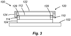
Fig. 3 illustrates a cross-sectional side view of alithographic reticle system 100 according to a further variation. Thesystem 100 shown inFig. 3 includes elements corresponding to those inFig. 1 . Thesystem 100 shown inFig. 3 merely differs from thesystem 100 shown inFig. 1 in that thesecond pellicle frame 120 is arranged in abutment with an outer sidewall surface of thefirst pellicle frame 114. Thesecond pellicle frame 124 is accordingly arranged to grip about, in a snugly fitting manner, about an outer sidewall surface of thefirst pellicle frame 114. Thesecond pellicle frame 124 may slidably bear against the outer sidewall surfaces of thefirst pellicle frame 114. - To improve the reliability of the releasable attachment of the
second pellicle frame 124 to thefirst pellicle frame 114, coupling members may be provided as described with respect to thesecond pellicle frame 124 and thefirst pellicle frame 114 in connection withFig. 1 . - A sealed space is formed between the
first pellicle membrane 112 and thesecond pellicle membrane 122. The space is defined by the portions of the inner sidewall surfaces of thesecond pellicle frame 124 protruding above thefirst pellicle membrane 112, thefirst pellicle membrane 112 and thesecond pellicle membrane 122. -
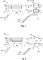
Fig. 4 is a schematic illustration of alithographic exposure tool 200, hereinafter referred to as thetool 200. Thetool 200 includes thereticle system 100. The tool includes alight source 206 for emitting light or radiation R. Thelight source 206 may be a DUV light source or an EUV light source, depending on the type of lithographic tool. - The
tool 200 includes asubstrate support 202 for supporting a substrate orwafer 204, which is to be processed. - The
tool 200 includes anoptical system 210 for directing light from thelight source 206 towards thesubstrate support 202 and thesubstrate 204 via thereticle 104. As schematically indicated the light R will hence propagate from the light source and pass through the first andsecond pellicle membranes substrate 204. - During a pellicle exchange or replacement method, the
reticle 104, thefirst pellicle 110 and thesecond pellicle 120 may be unloaded from thetool 200. Thereticle 104 may be released from thereticle support 102 and transported by an automatic unloading mechanism to aload lock 212 of thetool 200. This is schematically shown by the arrow A. The combination of thereticle 104, the first pellicle and thesecond pellicle 120 may subsequently be unloaded from theload lock 212 via a load port of theload lock 212. This is schematically shown by the arrow B. - Outside of the
tool 200, thesecond pellicle 120 may be manually removed from thefirst pellicle 110. Athird pellicle 130 having a third pellicle membrane and being of a same design and configuration as thesecond pellicle 120 may be releasably mounted on thefirst pellicle 110. It should be noted that thefirst pellicle 110 remains mounted on thereticle 104 throughout this operation. - The combination of the
reticle 104, thefirst pellicle 110 and thethird pellicle 130 may subsequently be loaded into theload lock 210 via the load port of theload lock 212. This is schematically shown by the arrow C. Following vacuum pumping, the combination of thereticle 104, thefirst pellicle 110 and thethird pellicle 130 may be transported by an automatic loading mechanism to thereticle support 102. This is schematically shown by the arrow D. The loading mechanism may be implemented in a manner corresponding to a conventional loading mechanism of a conventional lithographic exposure tool. Thereticle 104 may be arranged on thereticle support 102. Lithographic operation may then be commenced. -
Fig. 5 is a schematic illustration of alithographic exposure tool 200 corresponding to thetool 200 shown inFig. 4 . InFig. 5 is however a different pellicle exchange method shown. - Instead of unloading the combination of the
reticle 104, thefirst pellicle 110 and thesecond pellicle 120, thesecond pellicle 120 is removed from thefirst pellicle 110 while thereticle 104 and thefirst pellicle 110 remains on thereticle support 102. Thesecond pellicle 120 is subsequently transferred to theload lock 212. This is schematically shown by the arrow A. Thetool 200 may include a mechanism for disengaging the coupling members of thepellicles second pellicle 120 may subsequently be unloaded from theload lock 212 via a load port of theload lock 212. This is schematically shown by the arrow B. - A
third pellicle 130 having a third pellicle membrane and being of a same design and configuration as thesecond pellicle 120 may loaded into theload lock 212 through the load port thereof. This is schematically shown by the arrow C. Following vacuum pumping, thethird pellicle 130 may be transported by an automatic loading mechanism to thereticle support 102 and be mounted on thefirst reticle 110. The loading mechanism may be implemented in a manner corresponding to a conventional loading mechanism of a conventional lithographic exposure tool. This is schematically shown by the arrow D. Thetool 200 may include a mechanism for engaging the coupling members of thepellicles - Alternatively, the
second pellicle 120 may be transferred to a storage location (not shown), for instance a pellicle cartridge, of thetool 200. Thesecond pellicle 120 may for instance be transferred to a portion of the storage location intended for used pellicles. Correspondingly, thethird pellicle 130 may be transferred from the storage location to thereticle support 102 and be mounted on thefirst reticle 110. Thethird pellicle 130 may for instance be transferred from a portion of the storage location intended for un-used pellicles. The pellicle exchange may thereby be made even more automatic. The storage location may be emptied and/or replenished as needed during maintenance of thetool 200. - In the above the inventive concept has mainly been described with reference to a limited number of examples. However, as is readily appreciated by a person skilled in the art, other examples than the ones disclosed above are equally possible within the scope of the inventive concept, as defined by the appended claims. For instance, although in the above the
first pellicle 110 has been shown to have a same footprint as thereticle 104, it is also possible to form thefirst pellicle 110 with a smaller footprint than thereticle 104. This may be suitable for instance if the pattern is formed on only a sub-region of the main surface of thereticle 104. In such a configuration, thesecond pellicle 120 may be releasably mounted on the main surface of thereticle 104. Moreover, inFig. 4 and 5 thetool 200 was described in connection with thereticle system 100 shown inFig. 1 . However, it is equally possible to use the variations of thereticle system 100 shown inFig. 2 and3 in thetool 200.
Claims (15)
- A lithographic reticle system (100) comprising:a reticle (104),a first pellicle membrane (112) mounted in front of the reticle (104), anda second pellicle membrane (122) mounted in front of the first pellicle membrane (112),wherein the first pellicle membrane (112) is arranged between the reticle (104) and the second pellicle membrane (122), andwherein the second pellicle membrane (122) is releasably mounted in relation to the first pellicle membrane (112) and the reticle (104).
- A system according to claim 1, further comprising a first pellicle frame (114) supporting the first pellicle membrane (112), the first pellicle frame (114) being mounted on the reticle (102).
- A system according to any of the preceding claims, further comprising a second pellicle frame (124) supporting the second pellicle membrane (122), the second pellicle frame (124) being releasably mounted in relation to the first pellicle membrane (112) and the reticle (104).
- A system according to claim 3, further comprising a reticle support (102), wherein the reticle (104) is arranged on the reticle support (102) and the second pellicle frame (124) is releasably mounted on and in relation to the reticle support (102).
- A system according to claim 3, wherein the second pellicle frame (124) is releasably mounted on and in relation to a first pellicle frame (114) supporting the first pellicle membrane (112).
- A system according to claim 5, wherein the second pellicle frame (124) is arranged in abutment with an outer sidewall surface of the first pellicle frame (114).
- A system according to claim 5, wherein the second pellicle frame (124) is arranged on a top surface of the first pellicle frame (114).
- A system according to any one of claims 3-7, wherein the second pellicle frame (124) includes a mechanical coupling member (129) adapted to releasably engage with a mechanical coupling member (129) of a first pellicle frame (114) or of a reticle support (102) adapted to support the reticle (104).
- A system according to any one of claims 3-7, wherein the second pellicle frame (124) includes a magnetic coupling member (129) adapted to magnetically couple with a magnetic coupling member (129) of a first pellicle frame (114) or of a reticle support (102) adapted to support the reticle (104).
- A system according to any of the preceding claims, wherein the second pellicle frame (124) includes a gas inlet (126).
- A system according to any one of the preceding claims, wherein the first pellicle membrane (112) and the second pellicle membrane (122) are separated by a distance.
- A lithographic exposure tool (200) comprising:a light source (206),a substrate support (202),a reticle system (100) according to any one of the preceding claims, andan optical system (210) for directing light from the light source towards the substrate support via the reticle of the reticle system.
- A lithographic exposure tool according to claim 12, wherein the light source is an extreme ultraviolet light source.
- A method for exchanging a pellicle membrane of a lithographic exposure tool according to any of claims 12-13, the method comprising:unloading the reticle (104), the first pellicle membrane (112) and the second pellicle membrane (122) from the lithographic exposure tool (200),removing the second pellicle membrane (122) in front of the first pellicle membrane (112), wherein the first pellicle membrane (112) remains on the reticle (104),releasably mounting a third pellicle membrane (132) in front of the first pellicle membrane (112), andloading the reticle (104), the first pellicle membrane (112) and the third pellicle membrane (132) into the lithographic exposure tool.
- A method for exchanging a pellicle membrane inside a lithographic exposure tool according to any of claims 12-13, the method comprising:removing the second pellicle membrane (122) in front of the first pellicle membrane (112), wherein the first pellicle membrane (112) remains on the reticle (104), andreleasably mounting a third pellicle membrane (132) in front of the first pellicle membrane (112).
Priority Applications (4)
| Application Number | Priority Date | Filing Date | Title |
|---|---|---|---|
| EP17171170.8A EP3404485B1 (en) | 2017-05-15 | 2017-05-15 | A lithographic reticle system |
| US15/979,813 US10353284B2 (en) | 2017-05-15 | 2018-05-15 | Lithographic reticle system |
| CN201810462327.9A CN108873600A (en) | 2017-05-15 | 2018-05-15 | A kind of photo mask board system |
| JP2018093972A JP6854259B2 (en) | 2017-05-15 | 2018-05-15 | Lithography reticle system |
Applications Claiming Priority (1)
| Application Number | Priority Date | Filing Date | Title |
|---|---|---|---|
| EP17171170.8A EP3404485B1 (en) | 2017-05-15 | 2017-05-15 | A lithographic reticle system |
Publications (2)
| Publication Number | Publication Date |
|---|---|
| EP3404485A1 EP3404485A1 (en) | 2018-11-21 |
| EP3404485B1 true EP3404485B1 (en) | 2019-07-03 |
Family
ID=58709411
Family Applications (1)
| Application Number | Title | Priority Date | Filing Date |
|---|---|---|---|
| EP17171170.8A Active EP3404485B1 (en) | 2017-05-15 | 2017-05-15 | A lithographic reticle system |
Country Status (4)
| Country | Link |
|---|---|
| US (1) | US10353284B2 (en) |
| EP (1) | EP3404485B1 (en) |
| JP (1) | JP6854259B2 (en) |
| CN (1) | CN108873600A (en) |
Families Citing this family (10)
| Publication number | Priority date | Publication date | Assignee | Title |
|---|---|---|---|---|
| US11156927B1 (en) * | 2018-04-24 | 2021-10-26 | Kla Corporation | System and method for switching between an EUV pellicle and an optical pellicle |
| CN112840016A (en) | 2018-10-16 | 2021-05-25 | 东曹株式会社 | Cell culture substrate, method for producing cell culture substrate, and method for producing spheroid |
| EP3671342B1 (en) * | 2018-12-20 | 2021-03-17 | IMEC vzw | Induced stress for euv pellicle tensioning |
| TWI739179B (en) * | 2019-10-24 | 2021-09-11 | 美商微相科技股份有限公司 | Mask protection box structure |
| KR102194012B1 (en) * | 2020-04-10 | 2020-12-22 | 숭실대학교산학협력단 | Capacitor type pellicle using carbon nanotube ultrathin film and method for manufacturing the same |
| EP4165469A4 (en) | 2020-09-16 | 2023-12-13 | Lintec Of America, Inc. | Ultra-thin, ultra-low density films for euv lithography |
| CN112631066A (en) * | 2021-01-11 | 2021-04-09 | 长江存储科技有限责任公司 | Photomask protection structure, photomask substrate packaging method and photoetching method |
| US20230066653A1 (en) * | 2021-08-30 | 2023-03-02 | Taiwan Semiconductor Manufacturing Company, Ltd. | Reticle enclosure for lithography systems |
| CN113900352A (en) * | 2021-09-06 | 2022-01-07 | 长江存储科技有限责任公司 | Mask structure, manufacturing method thereof and photoetching method |
| CN116577967B (en) * | 2023-04-28 | 2024-01-30 | 广东科视光学技术股份有限公司 | Method for automatically opening and closing frame |
Family Cites Families (22)
| Publication number | Priority date | Publication date | Assignee | Title |
|---|---|---|---|---|
| JPS59189643U (en) * | 1983-05-31 | 1984-12-15 | シャープ株式会社 | Pellicle attachment device |
| JPH0342153U (en) * | 1989-08-31 | 1991-04-22 | ||
| JPH03263046A (en) * | 1990-03-14 | 1991-11-22 | Matsushita Electron Corp | Pellicle for photomask |
| JPH04283748A (en) * | 1991-03-13 | 1992-10-08 | Fujitsu Ltd | Pellicle |
| US6317479B1 (en) * | 1996-05-17 | 2001-11-13 | Canon Kabushiki Kaisha | X-ray mask, and exposure method and apparatus using the same |
| JPH09306820A (en) * | 1996-05-17 | 1997-11-28 | Canon Inc | X-ray mask structure, manufacture thereof, method and device for x-ray exposure, and semiconductor device and manufacture therefor |
| JPH09320935A (en) * | 1996-05-28 | 1997-12-12 | Canon Inc | X-ray mask, x-ray aligner using the x-ray mask, manufacture of semiconductor device which uses the x-ray mask, and semiconductor device manufactured by using the x-ray mask |
| JP4363725B2 (en) * | 1999-11-19 | 2009-11-11 | 旭化成イーマテリアルズ株式会社 | Pellicle |
| JP2002236352A (en) * | 2001-02-09 | 2002-08-23 | Umc Japan | Pellicle |
| US7061589B2 (en) * | 2002-09-03 | 2006-06-13 | Taiwan Semiconductor Manufacturing Company, Ltd. | Apparatus and method for mounting a hard pellicle |
| US7068347B2 (en) * | 2002-12-20 | 2006-06-27 | Intel Corporation | Apparatus for reducing pellicle darkening |
| JP2005234112A (en) * | 2004-02-18 | 2005-09-02 | Seiko Epson Corp | Photomask unit and circulation system |
| US7767985B2 (en) * | 2006-12-26 | 2010-08-03 | Globalfoundries Inc. | EUV pellicle and method for fabricating semiconductor dies using same |
| CN102253610A (en) * | 2010-05-20 | 2011-11-23 | 中芯国际集成电路制造(上海)有限公司 | Installation method and frameworks for photomask protective film |
| US8586267B2 (en) * | 2011-09-12 | 2013-11-19 | Samsung Austin Semiconductor, L.P. | Removable transparent membrane for a pellicle |
| CN103246157A (en) * | 2013-05-21 | 2013-08-14 | 上海和辉光电有限公司 | Dustproof film framework, optical mask and installation method thereof |
| WO2015160185A1 (en) * | 2014-04-17 | 2015-10-22 | 한양대학교 산학협력단 | Pellicle for euv lithography |
| EP3196699A4 (en) * | 2014-09-19 | 2018-05-16 | Mitsui Chemicals, Inc. | Pellicle, production method thereof, exposure method |
| JP6520041B2 (en) * | 2014-10-21 | 2019-05-29 | 凸版印刷株式会社 | Pellicle |
| JP2017032819A (en) * | 2015-08-03 | 2017-02-09 | 凸版印刷株式会社 | Photomask with pellicle and manufacturing method therefor |
| US9950349B2 (en) * | 2015-09-15 | 2018-04-24 | Internationa Business Machines Corporation | Drying an extreme ultraviolet (EUV) pellicle |
| US9835940B2 (en) * | 2015-09-18 | 2017-12-05 | Taiwan Semiconductor Manufacturing Company, Ltd. | Method to fabricate mask-pellicle system |
-
2017
- 2017-05-15 EP EP17171170.8A patent/EP3404485B1/en active Active
-
2018
- 2018-05-15 JP JP2018093972A patent/JP6854259B2/en active Active
- 2018-05-15 CN CN201810462327.9A patent/CN108873600A/en active Pending
- 2018-05-15 US US15/979,813 patent/US10353284B2/en active Active
Non-Patent Citations (1)
| Title |
|---|
| None * |
Also Published As
| Publication number | Publication date |
|---|---|
| US20180329290A1 (en) | 2018-11-15 |
| JP2018194841A (en) | 2018-12-06 |
| CN108873600A (en) | 2018-11-23 |
| JP6854259B2 (en) | 2021-04-07 |
| US10353284B2 (en) | 2019-07-16 |
| EP3404485A1 (en) | 2018-11-21 |
Similar Documents
| Publication | Publication Date | Title |
|---|---|---|
| EP3404485B1 (en) | A lithographic reticle system | |
| US6715495B2 (en) | Reduced particle contamination manufacturing and packaging for reticles | |
| JP2022066392A (en) | Mask assembly | |
| KR101968675B1 (en) | Lithographic apparatus and method | |
| KR101496076B1 (en) | Substrate transfer apparatus, substrate transfer method and exposure apparatus | |
| KR100714470B1 (en) | Container for a mask, method of transferring lithographic masks therein and method of scanning a mask in a container | |
| JP6325518B2 (en) | Reticle handling apparatus and method in EUV reticle inspection tool | |
| US9457947B2 (en) | Lithographic apparatus and device manufacturing method | |
| US20080024751A1 (en) | Reticle holding member, reticle stage, exposure apparatus, projection-exposure method and device manufacturing method | |
| US20070211232A1 (en) | Thermophoretic Techniques for Protecting Reticles from Contaminants | |
| US20180174873A1 (en) | Apparatus And Method For Processing Thin Substrates | |
| JP2006041499A (en) | Transfer of lithography apparatus and patterning device | |
| TWI812779B (en) | Lithographic system and method | |
| US8960928B2 (en) | Pellicle frame | |
| JP2005268464A (en) | Reticle cover and exposure apparatus | |
| JP6361964B2 (en) | Device manufacturing equipment | |
| TW202347571A (en) | Stocker pod, method and stocker for storing a semiconductor fabrication article | |
| NL2033682A (en) | Lithographic method by using a photomask contained in a transparent pod | |
| JP2011054999A (en) | Apparatus and method for exposure |
Legal Events
| Date | Code | Title | Description |
|---|---|---|---|
| PUAI | Public reference made under article 153(3) epc to a published international application that has entered the european phase |
Free format text: ORIGINAL CODE: 0009012 |
|
| STAA | Information on the status of an ep patent application or granted ep patent |
Free format text: STATUS: THE APPLICATION HAS BEEN PUBLISHED |
|
| AK | Designated contracting states |
Kind code of ref document: A1 Designated state(s): AL AT BE BG CH CY CZ DE DK EE ES FI FR GB GR HR HU IE IS IT LI LT LU LV MC MK MT NL NO PL PT RO RS SE SI SK SM TR |
|
| AX | Request for extension of the european patent |
Extension state: BA ME |
|
| STAA | Information on the status of an ep patent application or granted ep patent |
Free format text: STATUS: REQUEST FOR EXAMINATION WAS MADE |
|
| 17P | Request for examination filed |
Effective date: 20181127 |
|
| RBV | Designated contracting states (corrected) |
Designated state(s): AL AT BE BG CH CY CZ DE DK EE ES FI FR GB GR HR HU IE IS IT LI LT LU LV MC MK MT NL NO PL PT RO RS SE SI SK SM TR |
|
| GRAP | Despatch of communication of intention to grant a patent |
Free format text: ORIGINAL CODE: EPIDOSNIGR1 |
|
| STAA | Information on the status of an ep patent application or granted ep patent |
Free format text: STATUS: GRANT OF PATENT IS INTENDED |
|
| INTG | Intention to grant announced |
Effective date: 20190212 |
|
| GRAS | Grant fee paid |
Free format text: ORIGINAL CODE: EPIDOSNIGR3 |
|
| GRAA | (expected) grant |
Free format text: ORIGINAL CODE: 0009210 |
|
| STAA | Information on the status of an ep patent application or granted ep patent |
Free format text: STATUS: THE PATENT HAS BEEN GRANTED |
|
| AK | Designated contracting states |
Kind code of ref document: B1 Designated state(s): AL AT BE BG CH CY CZ DE DK EE ES FI FR GB GR HR HU IE IS IT LI LT LU LV MC MK MT NL NO PL PT RO RS SE SI SK SM TR |
|
| REG | Reference to a national code |
Ref country code: GB Ref legal event code: FG4D |
|
| REG | Reference to a national code |
Ref country code: CH Ref legal event code: EP Ref country code: AT Ref legal event code: REF Ref document number: 1151707 Country of ref document: AT Kind code of ref document: T Effective date: 20190715 |
|
| REG | Reference to a national code |
Ref country code: IE Ref legal event code: FG4D |
|
| REG | Reference to a national code |
Ref country code: DE Ref legal event code: R096 Ref document number: 602017004938 Country of ref document: DE |
|
| REG | Reference to a national code |
Ref country code: NL Ref legal event code: FP |
|
| REG | Reference to a national code |
Ref country code: LT Ref legal event code: MG4D |
|
| REG | Reference to a national code |
Ref country code: AT Ref legal event code: MK05 Ref document number: 1151707 Country of ref document: AT Kind code of ref document: T Effective date: 20190703 |
|
| PG25 | Lapsed in a contracting state [announced via postgrant information from national office to epo] |
Ref country code: PT Free format text: LAPSE BECAUSE OF FAILURE TO SUBMIT A TRANSLATION OF THE DESCRIPTION OR TO PAY THE FEE WITHIN THE PRESCRIBED TIME-LIMIT Effective date: 20191104 Ref country code: HR Free format text: LAPSE BECAUSE OF FAILURE TO SUBMIT A TRANSLATION OF THE DESCRIPTION OR TO PAY THE FEE WITHIN THE PRESCRIBED TIME-LIMIT Effective date: 20190703 Ref country code: CZ Free format text: LAPSE BECAUSE OF FAILURE TO SUBMIT A TRANSLATION OF THE DESCRIPTION OR TO PAY THE FEE WITHIN THE PRESCRIBED TIME-LIMIT Effective date: 20190703 Ref country code: LT Free format text: LAPSE BECAUSE OF FAILURE TO SUBMIT A TRANSLATION OF THE DESCRIPTION OR TO PAY THE FEE WITHIN THE PRESCRIBED TIME-LIMIT Effective date: 20190703 Ref country code: BG Free format text: LAPSE BECAUSE OF FAILURE TO SUBMIT A TRANSLATION OF THE DESCRIPTION OR TO PAY THE FEE WITHIN THE PRESCRIBED TIME-LIMIT Effective date: 20191003 Ref country code: SE Free format text: LAPSE BECAUSE OF FAILURE TO SUBMIT A TRANSLATION OF THE DESCRIPTION OR TO PAY THE FEE WITHIN THE PRESCRIBED TIME-LIMIT Effective date: 20190703 Ref country code: AT Free format text: LAPSE BECAUSE OF FAILURE TO SUBMIT A TRANSLATION OF THE DESCRIPTION OR TO PAY THE FEE WITHIN THE PRESCRIBED TIME-LIMIT Effective date: 20190703 Ref country code: NO Free format text: LAPSE BECAUSE OF FAILURE TO SUBMIT A TRANSLATION OF THE DESCRIPTION OR TO PAY THE FEE WITHIN THE PRESCRIBED TIME-LIMIT Effective date: 20191003 |
|
| PG25 | Lapsed in a contracting state [announced via postgrant information from national office to epo] |
Ref country code: IS Free format text: LAPSE BECAUSE OF FAILURE TO SUBMIT A TRANSLATION OF THE DESCRIPTION OR TO PAY THE FEE WITHIN THE PRESCRIBED TIME-LIMIT Effective date: 20191103 Ref country code: AL Free format text: LAPSE BECAUSE OF FAILURE TO SUBMIT A TRANSLATION OF THE DESCRIPTION OR TO PAY THE FEE WITHIN THE PRESCRIBED TIME-LIMIT Effective date: 20190703 Ref country code: ES Free format text: LAPSE BECAUSE OF FAILURE TO SUBMIT A TRANSLATION OF THE DESCRIPTION OR TO PAY THE FEE WITHIN THE PRESCRIBED TIME-LIMIT Effective date: 20190703 Ref country code: GR Free format text: LAPSE BECAUSE OF FAILURE TO SUBMIT A TRANSLATION OF THE DESCRIPTION OR TO PAY THE FEE WITHIN THE PRESCRIBED TIME-LIMIT Effective date: 20191004 Ref country code: LV Free format text: LAPSE BECAUSE OF FAILURE TO SUBMIT A TRANSLATION OF THE DESCRIPTION OR TO PAY THE FEE WITHIN THE PRESCRIBED TIME-LIMIT Effective date: 20190703 Ref country code: RS Free format text: LAPSE BECAUSE OF FAILURE TO SUBMIT A TRANSLATION OF THE DESCRIPTION OR TO PAY THE FEE WITHIN THE PRESCRIBED TIME-LIMIT Effective date: 20190703 |
|
| PG25 | Lapsed in a contracting state [announced via postgrant information from national office to epo] |
Ref country code: TR Free format text: LAPSE BECAUSE OF FAILURE TO SUBMIT A TRANSLATION OF THE DESCRIPTION OR TO PAY THE FEE WITHIN THE PRESCRIBED TIME-LIMIT Effective date: 20190703 |
|
| RAP2 | Party data changed (patent owner data changed or rights of a patent transferred) |
Owner name: IMEC VZW Owner name: IMEC USA NANOELECTRONICS DESIGN CENTER, INC. |
|
| PG25 | Lapsed in a contracting state [announced via postgrant information from national office to epo] |
Ref country code: EE Free format text: LAPSE BECAUSE OF FAILURE TO SUBMIT A TRANSLATION OF THE DESCRIPTION OR TO PAY THE FEE WITHIN THE PRESCRIBED TIME-LIMIT Effective date: 20190703 Ref country code: PL Free format text: LAPSE BECAUSE OF FAILURE TO SUBMIT A TRANSLATION OF THE DESCRIPTION OR TO PAY THE FEE WITHIN THE PRESCRIBED TIME-LIMIT Effective date: 20190703 Ref country code: DK Free format text: LAPSE BECAUSE OF FAILURE TO SUBMIT A TRANSLATION OF THE DESCRIPTION OR TO PAY THE FEE WITHIN THE PRESCRIBED TIME-LIMIT Effective date: 20190703 Ref country code: RO Free format text: LAPSE BECAUSE OF FAILURE TO SUBMIT A TRANSLATION OF THE DESCRIPTION OR TO PAY THE FEE WITHIN THE PRESCRIBED TIME-LIMIT Effective date: 20190703 Ref country code: IT Free format text: LAPSE BECAUSE OF FAILURE TO SUBMIT A TRANSLATION OF THE DESCRIPTION OR TO PAY THE FEE WITHIN THE PRESCRIBED TIME-LIMIT Effective date: 20190703 |
|
| PG25 | Lapsed in a contracting state [announced via postgrant information from national office to epo] |
Ref country code: IS Free format text: LAPSE BECAUSE OF FAILURE TO SUBMIT A TRANSLATION OF THE DESCRIPTION OR TO PAY THE FEE WITHIN THE PRESCRIBED TIME-LIMIT Effective date: 20200224 Ref country code: SK Free format text: LAPSE BECAUSE OF FAILURE TO SUBMIT A TRANSLATION OF THE DESCRIPTION OR TO PAY THE FEE WITHIN THE PRESCRIBED TIME-LIMIT Effective date: 20190703 Ref country code: SM Free format text: LAPSE BECAUSE OF FAILURE TO SUBMIT A TRANSLATION OF THE DESCRIPTION OR TO PAY THE FEE WITHIN THE PRESCRIBED TIME-LIMIT Effective date: 20190703 |
|
| REG | Reference to a national code |
Ref country code: DE Ref legal event code: R097 Ref document number: 602017004938 Country of ref document: DE |
|
| PLBE | No opposition filed within time limit |
Free format text: ORIGINAL CODE: 0009261 |
|
| STAA | Information on the status of an ep patent application or granted ep patent |
Free format text: STATUS: NO OPPOSITION FILED WITHIN TIME LIMIT |
|
| PG2D | Information on lapse in contracting state deleted |
Ref country code: IS |
|
| 26N | No opposition filed |
Effective date: 20200603 |
|
| REG | Reference to a national code |
Ref country code: DE Ref legal event code: R119 Ref document number: 602017004938 Country of ref document: DE |
|
| PG25 | Lapsed in a contracting state [announced via postgrant information from national office to epo] |
Ref country code: MC Free format text: LAPSE BECAUSE OF FAILURE TO SUBMIT A TRANSLATION OF THE DESCRIPTION OR TO PAY THE FEE WITHIN THE PRESCRIBED TIME-LIMIT Effective date: 20190703 Ref country code: LI Free format text: LAPSE BECAUSE OF NON-PAYMENT OF DUE FEES Effective date: 20200531 Ref country code: CH Free format text: LAPSE BECAUSE OF NON-PAYMENT OF DUE FEES Effective date: 20200531 |
|
| REG | Reference to a national code |
Ref country code: BE Ref legal event code: MM Effective date: 20200531 |
|
| PG25 | Lapsed in a contracting state [announced via postgrant information from national office to epo] |
Ref country code: LU Free format text: LAPSE BECAUSE OF NON-PAYMENT OF DUE FEES Effective date: 20200515 |
|
| PG25 | Lapsed in a contracting state [announced via postgrant information from national office to epo] |
Ref country code: FR Free format text: LAPSE BECAUSE OF NON-PAYMENT OF DUE FEES Effective date: 20200531 Ref country code: IE Free format text: LAPSE BECAUSE OF NON-PAYMENT OF DUE FEES Effective date: 20200515 |
|
| PG25 | Lapsed in a contracting state [announced via postgrant information from national office to epo] |
Ref country code: BE Free format text: LAPSE BECAUSE OF NON-PAYMENT OF DUE FEES Effective date: 20200531 Ref country code: DE Free format text: LAPSE BECAUSE OF NON-PAYMENT OF DUE FEES Effective date: 20201201 |
|
| GBPC | Gb: european patent ceased through non-payment of renewal fee |
Effective date: 20210515 |
|
| PG25 | Lapsed in a contracting state [announced via postgrant information from national office to epo] |
Ref country code: GB Free format text: LAPSE BECAUSE OF NON-PAYMENT OF DUE FEES Effective date: 20210515 |
|
| PG25 | Lapsed in a contracting state [announced via postgrant information from national office to epo] |
Ref country code: MT Free format text: LAPSE BECAUSE OF FAILURE TO SUBMIT A TRANSLATION OF THE DESCRIPTION OR TO PAY THE FEE WITHIN THE PRESCRIBED TIME-LIMIT Effective date: 20190703 Ref country code: CY Free format text: LAPSE BECAUSE OF FAILURE TO SUBMIT A TRANSLATION OF THE DESCRIPTION OR TO PAY THE FEE WITHIN THE PRESCRIBED TIME-LIMIT Effective date: 20190703 |
|
| PG25 | Lapsed in a contracting state [announced via postgrant information from national office to epo] |
Ref country code: MK Free format text: LAPSE BECAUSE OF FAILURE TO SUBMIT A TRANSLATION OF THE DESCRIPTION OR TO PAY THE FEE WITHIN THE PRESCRIBED TIME-LIMIT Effective date: 20190703 |
|
| P01 | Opt-out of the competence of the unified patent court (upc) registered |
Effective date: 20230513 |
|
| PGFP | Annual fee paid to national office [announced via postgrant information from national office to epo] |
Ref country code: NL Payment date: 20230419 Year of fee payment: 7 |
|
| PGFP | Annual fee paid to national office [announced via postgrant information from national office to epo] |
Ref country code: FI Payment date: 20230419 Year of fee payment: 7 |
|
| PG25 | Lapsed in a contracting state [announced via postgrant information from national office to epo] |
Ref country code: SI Free format text: LAPSE BECAUSE OF FAILURE TO SUBMIT A TRANSLATION OF THE DESCRIPTION OR TO PAY THE FEE WITHIN THE PRESCRIBED TIME-LIMIT Effective date: 20190703 |