EP3404383A1 - Vorrichtung und verfahren zum messen von temperaturen mit thermoelementen - Google Patents
Vorrichtung und verfahren zum messen von temperaturen mit thermoelementen Download PDFInfo
- Publication number
- EP3404383A1 EP3404383A1 EP18167749.3A EP18167749A EP3404383A1 EP 3404383 A1 EP3404383 A1 EP 3404383A1 EP 18167749 A EP18167749 A EP 18167749A EP 3404383 A1 EP3404383 A1 EP 3404383A1
- Authority
- EP
- European Patent Office
- Prior art keywords
- thermocouple
- thermocouples
- voltage
- connection
- negative pole
- Prior art date
- Legal status (The legal status is an assumption and is not a legal conclusion. Google has not performed a legal analysis and makes no representation as to the accuracy of the status listed.)
- Granted
Links
Images
Classifications
-
- G—PHYSICS
- G01—MEASURING; TESTING
- G01K—MEASURING TEMPERATURE; MEASURING QUANTITY OF HEAT; THERMALLY-SENSITIVE ELEMENTS NOT OTHERWISE PROVIDED FOR
- G01K7/00—Measuring temperature based on the use of electric or magnetic elements directly sensitive to heat ; Power supply therefor, e.g. using thermoelectric elements
- G01K7/02—Measuring temperature based on the use of electric or magnetic elements directly sensitive to heat ; Power supply therefor, e.g. using thermoelectric elements using thermoelectric elements, e.g. thermocouples
- G01K7/021—Particular circuit arrangements
-
- G—PHYSICS
- G01—MEASURING; TESTING
- G01K—MEASURING TEMPERATURE; MEASURING QUANTITY OF HEAT; THERMALLY-SENSITIVE ELEMENTS NOT OTHERWISE PROVIDED FOR
- G01K15/00—Testing or calibrating of thermometers
- G01K15/007—Testing
-
- G—PHYSICS
- G01—MEASURING; TESTING
- G01K—MEASURING TEMPERATURE; MEASURING QUANTITY OF HEAT; THERMALLY-SENSITIVE ELEMENTS NOT OTHERWISE PROVIDED FOR
- G01K7/00—Measuring temperature based on the use of electric or magnetic elements directly sensitive to heat ; Power supply therefor, e.g. using thermoelectric elements
- G01K7/02—Measuring temperature based on the use of electric or magnetic elements directly sensitive to heat ; Power supply therefor, e.g. using thermoelectric elements using thermoelectric elements, e.g. thermocouples
Definitions
- the invention relates to a device for measuring temperatures with embedded in a protective tube redundant thermocouples and a method for temperature measurement.
- thermowell thermocouples Generic embedded in a thermowell thermocouples are known from the published patent application DE 101 09 828 A1 , Embedding in a protective tube is used to protect against aggressive environmental influences of the measuring point.
- thermocouples For safety-relevant measuring tasks, it is known to use two thermocouples in a thermowell with independent measured value evaluation. This achieves redundancy. If the measured values deviate from one another, a malfunction can be concluded.
- the protective jacket is by design usually connected to the protective conductor potential (ground) of the device and thus the device electronics.
- thermocouples When measuring the temperature through thermocouples, only very low voltages in the millivolt range occur due to the principle. These low voltages are amplified and evaluated by an electrical amplifier. Depending on the type of evaluation, a limb of a thermocouple lies at a different electrical potential than the protective tube. The measurement takes place differentially between both leg potentials.
- thermocouples are electrically isolated. This is usually done in that the thermocouples are used in the protection tube in the production and are cast with an insulating compound.
- the parasitic resistance of the protective jacket to the individual thermocouples should ideally be very high in order not to influence the measurement result. Nevertheless, this resistance can be particularly high Temperatures of several hundred degrees Celsius are much smaller and sink into the two-digit kilo-ohm range. Because of the existing internal resistance of each thermocouple, this parasitic resistance between sheath and thermocouple on the free measuring leg affects the thermoelectric voltage. A leakage current flows from the base point via the supply line of the thermocouple and via the parasitic resistors. Here, the current causes a voltage drop, which distorts the measured thermal voltage. The effect occurs to the same extent on both redundant thermocouples. A plausibility comparison of the two temperatures would not reveal a falsified temperature measurement.
- thermocouples embedded in the protective tube each have a base point connected to a potential base at a respective terminal of different polarity. This may be a connection from one common or two equal voltage sources or may be a ground point with a 0 volt potential.
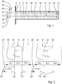
- FIG. 1 shows the inventive device for measuring temperatures.
- a protective tube 1 two thermocouples 11, 12 are introduced.
- the thermocouples 11, 12 each have thermocouple junctions 31, 32, to each of which a supply line 41, 42 to the negative pole and a respective supply line 51, 52 connects to the positive pole.
- the negative pole of the thermocouple junctions 31, 32 is marked with a thicker line.
- the leads 51, 52 and the leads 41, 42 are made of different materials, so that the thermoelectric effect can be used for measuring temperatures.
- the thermocouple junctions 31, 32 and the leads 41, 42, 51, 52 form the thermocouples 11, 12.
- the terminals 71, 72, 81, 82 allow the electrical connection to a her device not shown for the evaluation of the voltages.
- the protective tube 1 is optionally connected to a flange 2, with which the protective tube 1 can be fixed in operation at the temperature measuring point.
- a flange 2 With which the protective tube 1 can be fixed in operation at the temperature measuring point.
- Other mounting options are known in the art and included in the invention. Since the protective tube 1 is usually metallic and is connected by the connection with the measurement object electrically with this, the protective tube 1 is usually at ground potential.
- the leads 41, 42, 51, 52 must be electrically insulated from the protective tube. These are electrically isolated with an insulating 3 with respect to the protective tube 1 and each other.
- the insulating means 3 may for example be a cable insulation of the leads 41, 42, 51, 52.
- the insulating means 3 is formed by an insulating potting compound, which in the assembly of the thermocouples 11, 12 in the protective tube 1 in a liquid state is introduced and at the same time fixes the thermocouples in their position. Further embodiments of the insulating means 3 are also possible.
- the paired arrangement of the thermocouples 11, 12 is used for redundant temperature measurement in safety-critical applications. Thereby, the failure of one of the thermocouples 11, 12 can be easily detected.
- the apparatus for measuring temperatures may be exposed to high temperatures, degradation of the insulating means 3 may occur, with the result that the insulating effect wears off. According to the prior art, this can not be detected by comparing the measured values of the two thermocouples 11, 12, since the decreasing insulation acts on both thermocouples 11, 12 at the same time.
- the second lead 42 to the negative pole of the thermocouple junction 32 of the second thermocouple 12 and the first lead 51 to the positive pole of the thermocouple junction 31 of the first thermocouple 11 each connected to an electrical base point 61, 62, each having a Potential base 91, 92 is connected.
- These can be different potential bases as well as an identical potential basis.
- This may be a pole of a power supply or a ground connection, so that each leading to different poles of the thermocouple 11, 12 lead is pulled to this potential.
- This causes the thermocouples 11, 12 to be oppositely polarized. This has the consequence that voltage drops over a faulty insulation 3 have opposite effects on the thermoelectric voltage of the thermocouples 11, 12.
- thermocouples 11, 12 are here embedded in the protective tube 1 shown schematically.
- the connection points 31, 32 of the thermocouples 11, 12 are shown as voltage sources with the temperature-dependent voltage U_TC1 and U_TC2.
- the internal resistances R1.1 and R1.2 also represent the internal resistances of the leads 51, 41, 42, 52.
- the potentials TC + and TC- the measurement voltage are tapped at the electrical terminals 71, 72, 81, 82 for evaluation.
- the base points are marked with the reference numerals 61 and 62. At these base points, the potential is drawn to the voltage U_TC_Zero1, U_TC_Zero2 with the aid of a voltage source or a direct connection to ground.
- thermoelectric voltages are drawn in the direction of the potential of the protective tube (eg device ground).
- the parasitic resistances R2.1, R4.1, R2.2, R4.2 sink, both thermoelectric voltages are drawn in the direction of the potential of the protective tube (eg device ground).
- one of the thermovoltages is added to the base point potential (U_TC_Zero1) and the other thermovoltage is subtracted from the base point potential (U_TC_Zero2).
- the corruption due to the parasitic resistors R2.1, R4.1, R2.2, R4.2 which are too low acts in the same direction in each case.
- both measured values differ in the height of the measured voltages at the terminals 81, 71 and 72, 82. This difference can now be made plausible by comparing the measurement results. If the difference in the measured values becomes too high, an error in the insulation 3 can be detected. Because the influence of both measurements In the opposite direction, averaging of the two measured values (measured voltages) corrects a large part of the measurement error.
Landscapes
- Physics & Mathematics (AREA)
- General Physics & Mathematics (AREA)
- Measuring Temperature Or Quantity Of Heat (AREA)
- Investigating Or Analyzing Materials Using Thermal Means (AREA)
- Measurement Of Current Or Voltage (AREA)
Abstract
Description
- Die Erfindung betrifft eine Vorrichtung zum Messen von Temperaturen mit in einem Schutzrohr eingebetteten redundanten Thermoelementen und ein Verfahren zur Temperaturmessung.
- Gattungsgemäße in einem Schutzrohr eingebettete Thermoelemente sind bekannt aus der Offenlegungsschrift
DE 101 09 828 A1 . Die Einbettung in ein Schutzrohr erfolgt zum Schutz vor aggressiven Umgebungseinflüssen der Messstelle. - Für sicherheitsrelevante Messaufgaben ist es bekannt, zwei Thermoelemente in einem Schutzrohr mit unabhängiger Messwertauswertung zu verwenden. Dadurch wird eine Redundanz erreicht. Bei einem Abweichen der Messwerte voneinander kann auf eine Fehlfunktion geschlossen werden. Der Schutzmantel ist konstruktionsbedingt meist mit dem Schutzleiterpotential (Masse) des Gerätes und damit auch der Geräteelektronik verbunden.
- Bei der Temperaturmessung durch Thermoelemente treten prinzipbedingt nur sehr niedrige Spannungen im Millivolt-Bereich auf. Diese niedrigen Spannungen werden durch einen elektrischen Verstärker verstärkt und ausgewertet. Je nach Art der Auswertung liegt dabei ein Schenkel eines Thermoelementes auf einem anderen elektrischen Potential als das Schutzrohr. Die Messung findet differentiell zwischen beiden Schenkel-Potentialen statt.
- Zwar sind die beiden Thermoelemente elektrisch isoliert. Dies erfolgt in der Regel dadurch, dass bei der Herstellung die Thermoelemente in das Schutzrohr eingesetzt werden und mit einer Isoliermasse vergossen werden. Der parasitäre Widerstand vom Schutzmantel zu den einzelnen Thermoelementen sollte idealerweise sehr hoch sein, um das Messergebnis nicht zu beeinflussen. Dennoch kann dieser Widerstand insbesondere bei hohen Temperaturen von mehreren hundert Grad Celsius sehr viel kleiner werden und bis in den zweistelligen Kiloohm-Bereich sinken. Wegen des vorhandenen Innenwiderstandes eines jeden Thermoelementes wirkt sich dieser parasitäre Widerstand zwischen Mantel und Thermoelement am freien Messschenkel auf die Thermospannung aus. Ein Leckage-Strom fließt vom Basispunkt über die Zuleitung des Thermoelementes und über die parasitären Widerstände ab. Hierbei verursacht der Strom einen Spannungsabfall, der die gemessene Thermospannung verfälscht. Der Effekt tritt an beiden redundanten Thermoelementen in gleichem Maße auf. Ein Plausibilitätsvergleich der beiden Temperaturen würde eine verfälschte Temperaturmessung nicht aufdecken.
- Es ist daher Aufgabe der Erfindung, eine Vorrichtung zum Messen von Temperaturen mit redundanten Thermoelementen im Schutzrohr bereitzustellen, die die vorgenannten Nachteile vermeidet. Weitere Aufgabe ist es, ein Verfahren zum Messen mit vorgenannten Vorrichtung bereitzustellen, das die vorgenannten Nachteile vermeidet.
- Diese Aufgabe wird gemäß dem unabhängigen Vorrichtungsanspruch dadurch gelöst, dass die im Schutzrohr eingebetteten Thermoelemente an jeweils einem Anschluss mit unterschiedlicher Polarität jeweils einen Basispunkt aufweisen, der mit einer Potentialbasis verbunden ist. Dies kann ein Anschluss von einer gemeinsamen oder von zwei gleichen Spannungsquellen sein oder aber ein Massepunkt mit einem 0 Volt-Potential sein.
- Dies hat den Vorteil, dass bei nachlassender Isolierwirkung der Isoliermasse dies darin resultiert, dass sich die Beträge der Messwerte der beiden Thermoelemente in unterschiedliche Richtungen verschieben. Dies ergibt sich aus der entgegengesetzten unterschiedlichen Polung.
- Dadurch kann in einem erfindungsgemäßen Verfahren ein Defekt leicht erkannt und signalisiert werden.
- Die Erfindung wird nun anhand der Figuren detailliert erläutert.
- Es stellen dar:
-
Figur 1 : die erfindungsgemäße Vorrichtung, -
Figur 2 : das Ersatzschaltbild der erfindungsgemäßen Vorrichtung. -
Figur 1 zeigt die die erfindungsgemäße Vorrichtung zum Messen von Temperaturen. In einem Schutzrohr 1 sind zwei Thermoelemente 11, 12 eingebracht. Die Thermoelemente 11, 12 weisen jeweils Thermoelement-Verbindungsstellen 31, 32 auf, an welche sich jeweils eine Zuleitung 41, 42 zum negativen Pol und jeweils eine Zuleitung 51, 52 zum positiven Pol anschließt. Der negative Pol der Thermoelemente-Verbindungsstellen 31, 32 ist mit einer dickeren Linie gekennzeichnet. Die Zuleitungen 51, 52 und die Zuleitungen 41, 42 sind aus unterschiedlichem Material, so dass der thermoelektrische Effekt zum Messen von Temperaturen genutzt werden kann. Somit bilden die Thermoelement-Verbindungsstellen 31, 32 und die Zuleitungen 41, 42, 51, 52 die Thermoelemente 11, 12. Die Anschlüsse 71, 72, 81, 82 ermöglichen den elektrischen Anschluss an eine her nicht dargestellte Vorrichtung zur Auswertung der Spannungen. - Das Schutzrohr 1 ist optional mit einem Flansch 2 verbunden, mit dem das Schutzrohr 1 im Betrieb an der Temperaturmessstelle befestigt werden kann. Andere Befestigungsmöglichkeiten sind aus dem Stand der Technik bekannt und in der Erfindung eingeschlossen. Da das Schutzrohr 1 in der Regel metallisch ist und durch die Verbindung mit dem Messobjekt elektrisch mit diesem verbunden ist, liegt das Schutzrohr 1 in der Regel auf Massepotenzial. Die Zuleitungen 41, 42, 51, 52 müssen elektrisch gegenüber dem Schutzrohr isoliert sein. Dazu sind diese mit einem Isoliermittel 3 gegenüber dem Schutzrohr 1 und untereinander elektrisch isoliert. Das Isoliermittel 3 kann beispielsweise eine Kabelisolierung der Zuleitungen 41, 42, 51, 52 sein. Meist wird das Isoliermittel 3 jedoch durch eine isolierende Vergussmasse gebildet, die bei der Montage der Thermoelemente 11, 12 im Schutzrohr 1 in einem flüssigen Zustand eingebracht wird und zugleich die Thermoelemente in ihrer Lage fixiert. Weitere Ausgestaltungen des Isoliermittels 3 sind ebenfalls möglich. Die paarweise Anordnung der Thermoelemente 11, 12 dient der redundanten Temperaturmessung in sicherheitskritischen Anwendungen. Dadurch kann der Ausfall eines der Thermoelemente 11, 12 leicht erkannt werden. Da die Vorrichtung zum Messen von Temperaturen jedoch hohen Temperaturen ausgesetzt sein kann, kann es zu einer Degradation des Isoliermittels 3 kommen, mit der Folge, dass die Isolierwirkung nachlässt. Nach dem Stand der Technik kann dies nicht durch Vergleich der Messwerte der beiden Thermoelemente 11, 12 erkannt werden, da die nachlassende Isolierung auf beide Thermoelemente 11, 12 zugleich wirkt.
- Deshalb ist erfindungsgemäß die zweite Zuleitung 42 zum negativen Pol der Thermoelement-Verbindungsstelle 32 des zweiten Thermoelements 12 und die erste Zuleitung 51 zum positiven Pol der Thermoelement-Verbindungsstelle 31 des ersten Thermoelements 11 jeweils mit einem elektrischen Basispunkt 61, 62 verbunden, der mit jeweils einer Potenzialbasis 91, 92 verbunden ist. Dabei kann es sich um unterschiedliche Potenzialbasen als auch um eine identische Potenzialbasis handeln. Dies kann ein Pol einer Spannungsversorgung oder eine Masseverbindung sein, so dass jeweils eine zu unterschiedlichen Polen des Thermoelements 11, 12 führende Zuleitung auf dieses Potenzial gezogen wird. Dadurch wird bewirkt, dass die Thermoelemente 11, 12 entgegengesetzt polarisiert sind. Dies hat zur Folge, dass Spannungsabfälle über eine mangelhafte Isolierung 3 entgegengesetzte Wirkungen auf die Thermospannung der Thermoelemente 11, 12 haben.
- Dies soll nun anhand des Ersatzschaltbildes der erfindungsgemäßen Vorrichtung in
Figur 2 erläutert werden. Die inFigur 1 beschriebenen Thermoelemente 11, 12 sind hier eingebettet in das Schutzrohr 1 schematisch dargestellt. Die Verbindungsstellen 31, 32 der Thermoelemente 11, 12 werden als Spannungsquellen mit der temperaturabhängigen Spannung U_TC1 und U_TC2 dargestellt. Die Innenwiderstände R1.1 und R1.2 repräsentieren auch die Innenwiderstände der Zuleitungen 51, 41, 42, 52. Die Potenziale TC+ und TC- der Messspannung werden an den elektrischen Anschlüssen 71, 72, 81, 82 zur Auswertung abgegriffen. Die parasitären Widerstände des Isoliermittels 3 ausFigur 1 wird repräsentiert durch die Widerstände R2.1, R4.1, R2.2 und R4.2 zwischen der jeweiligen Zuleitung 51, 41, 42, 52 und der Masse des Schutzrohrs 1, sowie durch die Widerstände R3.1 und R3.2 zwischen den Zuleitungen 51 und 41 bzw. 42 und 52. Die Basispunkte sind mit den Bezugszeichen 61 und 62 gekennzeichnet. An diesen Basispunkten wird mit Hilfe einer Spannungsquelle oder einer direkten Verbindung zur Masse das Potenzial auf die Spannung U_TC_Zero1, U_TC_Zero2 gezogen. - Wegen des vorhandenen Innenwiderstandes R1.1, R1.2 eines jeden Thermoelementes wirkt sich dieser parasitäre Widerstand R2.1, R4.1, R2.2, R4.2 zwischen Mantel und Thermoelement am freien Messschenkel auf die Thermospannung aus. Wird ein Thermoelement 12 gegenüber dem anderen Thermoelement 11 hinsichtlich seiner seiner Polarität vertauscht, also eines mit dem positiven und eines mit dem negativen Schenkel an seinem elektrischen Basispunkt-Potential (TC_Zero) fixiert, muss diese Veränderung nur bei der Auswertung berücksichtigt werden. Sind die parasitären Widerstände R2.1, R4.1, R2.2, R4.2 ausreichend groß, muss nur das Vorzeichen dieser Thermospannung invertiert werden. Ansonsten hat die Vertauschung in diesem Fall keinen Einfluss auf die Thermospannung U_TC1, U_TC2. Erst wenn die parasitären Widerstände R2.1, R4.1, R2.2, R4.2 sinken, werden beide Thermospannungen in Richtung des Potentials des Schutzrohrs (z.B. Gerätemasse) gezogen. Dadurch wird in diesem Fall eine der Thermospannungen auf das Basispunktpotential (U_TC_Zero1) addiert und die andere Thermospannung vom Basispunktpotential (U_TC_Zero2) subtrahiert. Die Verfälschung durch die zu geringen parasitären Widerstände R2.1, R4.1, R2.2, R4.2 wirkt aber jeweils in die gleiche Richtung. Deswegen unterscheiden sich beide Messwerte in der Höhe der gemessenen Spannungen an den Anschlüssen 81, 71 und 72, 82. Dieser Unterschied kann nun mit einem Vergleich der Messergebnisse plausibilisiert werden. Wird der Unterschied der Messwerte zu hoch, kann damit ein Fehler in der Isolierung 3 entdeckt werden. Da die Beeinflussung beider Messungen in entgegengesetzter Richtung erfolgt, korrigiert eine Mittelwertbildung der beiden Messwerte (gemessene Spannungen) einen großen Teil des Messfehlers.
-
- 1
- Schutzrohr
- 2
- Flansch
- 3
- Isoliermittel
- 11
- Erstes Thermoelement
- 12
- Zweites Thermoelement
- 31
- Erste Thermoelement-Verbindungsstelle
- 32
- Zweite Thermoelement- Verbindungsstelle
- 41
- Erste Zuleitung zum positiven Pol
- 42
- Zweite Zuleitung zum positiven Pol
- 51
- Erste Zuleitung zum negativen Pol
- 52
- Zweite Zuleitung zum negativen Pol
- 61
- Erster elektrischer Basispunkt
- 62
- Zweiter elektrischer Basispunkt
- 71
- Erster elektrischer Anschluss am positiven Pol
- 72
- Zweiter elektrischer Anschluss am positiven Pol
- 81
- Erster elektrischer Anschluss am negativen Pol
- 82
- Zweiter elektrischer Anschluss am negativen Pol
- 91
- Erste Potentialbasis
- 92
- Zweite Potentialbasis
Claims (4)
- Vorrichtung zum Messen von Temperaturen, umfassend ein erstes Thermoelement (11) mit einer Zuleitung zum positiven Pol (41) und einer Zuleitung zum negativen Pol (51) einer Verbindungsstelle (31) und mit einem ersten elektrischen Anschluss (71) des positiven Pols und einem ersten elektrischen Anschluss (81) des negativen Pols, umfassend ein zweites Thermoelement (12) mit einer Zuleitung (42) zum positiven Pol (42) und einer Zuleitung zum negativen Pol (52) einer Verbindungsstelle (32) und mit einem zweiten elektrischen Anschluss (71) des positiven Pols und einem zweiten elektrischen Anschluss (81) des negativen Pols, wobei das erste (11) und das zweite Thermoelement (12) in einem gemeinsamen Schutzrohr (1) eingebettet sind, dadurch gekennzeichnet, dass jeweils eine Zuleitung (41, 52) zu den Polen jedes der Thermoelemente (11, 12) mit einem elektrischen Basispunkt (61, 62) direkt verbunden ist, dass die mit den Basispunkten (61, 62) direkt verbundenen Zuleitungen (41, 52) zu unterschiedlichen Polen der Thermoelement-Verbindungsstellen (31, 32) führen, und dass die elektrischen Basispunkte (61, 62) mit einer jeweils einer Potentialbasis (91, 92) verbunden sind mit annähernd gleichen Potentialen.
- Vorrichtung nach Anspruch 1, dadurch gekennzeichnet, dass die Potentialbasis (91, 92) durch einen Pol einer gemeinsamen Spannungsversorgung gebildet wird.
- Vorrichtung nach Anspruch 1, dadurch gekennzeichnet, dass die Potentialbasis (91, 92) durch einen Massepunkt gebildet wird.
- Verfahren zum Betreiben einer Vorrichtung nach einem der Ansprüche 1 bis 3, dadurch gekennzeichnet, dass die eine erste Spannung zwischen dem Anschluss des positiven Pols (71) und dem Anschluss des negativen Pols (81) des ersten Thermoelements (11) und eine zweite Spannung zwischen dem Anschluss des negativen Pols (72) und dem Anschluss des positiven Pols (82) des zweiten Thermoelements (12) gemessen wird, dass die invertierte erste Spannung mit der zweiten Spannung verglichen wird und bei einer Abweichung ein Fehler signalisiert wird.
Applications Claiming Priority (1)
| Application Number | Priority Date | Filing Date | Title |
|---|---|---|---|
| DE102017110445.3A DE102017110445B4 (de) | 2017-05-15 | 2017-05-15 | Vorrichtung und Verfahren zum Messen von Temperaturen mit Thermoelementen |
Publications (2)
| Publication Number | Publication Date |
|---|---|
| EP3404383A1 true EP3404383A1 (de) | 2018-11-21 |
| EP3404383B1 EP3404383B1 (de) | 2020-03-18 |
Family
ID=62017234
Family Applications (1)
| Application Number | Title | Priority Date | Filing Date |
|---|---|---|---|
| EP18167749.3A Active EP3404383B1 (de) | 2017-05-15 | 2018-04-17 | Vorrichtung und verfahren zum messen von temperaturen mit thermoelementen |
Country Status (4)
| Country | Link |
|---|---|
| EP (1) | EP3404383B1 (de) |
| DE (1) | DE102017110445B4 (de) |
| DK (1) | DK3404383T3 (de) |
| ES (1) | ES2785001T3 (de) |
Cited By (1)
| Publication number | Priority date | Publication date | Assignee | Title |
|---|---|---|---|---|
| CN109959463A (zh) * | 2019-03-12 | 2019-07-02 | 哈尔滨理工大学 | 一种快响应冗余膜式热电偶 |
Families Citing this family (1)
| Publication number | Priority date | Publication date | Assignee | Title |
|---|---|---|---|---|
| US11408779B2 (en) * | 2019-06-03 | 2022-08-09 | Daily Thermetrics Corporation | Temperature sensor and methods of use |
Citations (4)
| Publication number | Priority date | Publication date | Assignee | Title |
|---|---|---|---|---|
| JPS5560828A (en) * | 1978-11-01 | 1980-05-08 | Nippon Steel Corp | Detector for thermocouple failure |
| JPS5946525A (ja) * | 1982-09-03 | 1984-03-15 | Yokogawa Hokushin Electric Corp | 熱電対絶縁モニタ |
| DE10109828A1 (de) | 2001-03-01 | 2002-09-05 | Xcellsis Gmbh | Elekrische Temperaturmessvorrichtung |
| EP2511640A1 (de) * | 2011-04-14 | 2012-10-17 | Industrieofentechnik Frank Schubert GmbH & Co. KG. | Vorrichtung und Verfahren zum Prüfen eines Thermoelements |
Family Cites Families (6)
| Publication number | Priority date | Publication date | Assignee | Title |
|---|---|---|---|---|
| US6239351B1 (en) * | 1993-07-01 | 2001-05-29 | Hoskins Manufacturing Company | Multi-wire self-diagnostic thermocouple |
| JPH09152379A (ja) * | 1995-11-30 | 1997-06-10 | Natl Aerospace Lab | 熱電対を用いた温度計測装置 |
| GB2451693B (en) * | 2007-08-09 | 2011-12-14 | Weston Aerospace Ltd | Thermocouple Head Unit |
| DE102009005924A1 (de) * | 2008-06-16 | 2009-12-31 | Thermo- control Körtvélessy GmbH | Kompensiertes Thermoelementensystem |
| DE102010063474B4 (de) * | 2010-12-20 | 2014-02-13 | BSH Bosch und Siemens Hausgeräte GmbH | Kerntemperaturfühler |
| DE102012103952B3 (de) * | 2012-05-04 | 2013-08-29 | Temperaturmeßtechnik Geraberg GmbH | Messfühler für Anordnungen zur Temperaturüberwachung, insbesondere für Sicherheitstemperaturbegrenzer |
-
2017
- 2017-05-15 DE DE102017110445.3A patent/DE102017110445B4/de not_active Expired - Fee Related
-
2018
- 2018-04-17 ES ES18167749T patent/ES2785001T3/es active Active
- 2018-04-17 EP EP18167749.3A patent/EP3404383B1/de active Active
- 2018-04-17 DK DK18167749.3T patent/DK3404383T3/da active
Patent Citations (4)
| Publication number | Priority date | Publication date | Assignee | Title |
|---|---|---|---|---|
| JPS5560828A (en) * | 1978-11-01 | 1980-05-08 | Nippon Steel Corp | Detector for thermocouple failure |
| JPS5946525A (ja) * | 1982-09-03 | 1984-03-15 | Yokogawa Hokushin Electric Corp | 熱電対絶縁モニタ |
| DE10109828A1 (de) | 2001-03-01 | 2002-09-05 | Xcellsis Gmbh | Elekrische Temperaturmessvorrichtung |
| EP2511640A1 (de) * | 2011-04-14 | 2012-10-17 | Industrieofentechnik Frank Schubert GmbH & Co. KG. | Vorrichtung und Verfahren zum Prüfen eines Thermoelements |
Cited By (1)
| Publication number | Priority date | Publication date | Assignee | Title |
|---|---|---|---|---|
| CN109959463A (zh) * | 2019-03-12 | 2019-07-02 | 哈尔滨理工大学 | 一种快响应冗余膜式热电偶 |
Also Published As
| Publication number | Publication date |
|---|---|
| ES2785001T3 (es) | 2020-10-02 |
| DK3404383T3 (da) | 2020-04-14 |
| DE102017110445A1 (de) | 2018-11-15 |
| DE102017110445B4 (de) | 2020-02-13 |
| EP3404383B1 (de) | 2020-03-18 |
Similar Documents
| Publication | Publication Date | Title |
|---|---|---|
| DE102006045141B3 (de) | Magnetfeld-Sensor-Vorrichtung | |
| DE102017111410B4 (de) | Messungen in Schaltvorrichtungen | |
| DE102015113237A1 (de) | Temperaturmessgerät zur Messung der Temperatur eines in einem Behälter befindlichen Mediums | |
| DE102010029147A1 (de) | Verfahren zur Ermittlung der Temperatur eines Leistungshalbleiters | |
| EP2656034B1 (de) | Kerntemperaturfühler | |
| DE102020201240A1 (de) | Steckverbinderelement und Steckverbinder für Hochvoltanwendungen | |
| EP3404383B1 (de) | Vorrichtung und verfahren zum messen von temperaturen mit thermoelementen | |
| DE102010039904B4 (de) | Umgebungstemperaturabhängiger thermischer Schutz von Leistungsbauelementen | |
| DE202004021438U1 (de) | Anordnung von Sensorelementen zum zuverlässigen Messen einer Temperatur | |
| DE202016103030U1 (de) | Stecker, insbesondere mit einem Fahrzeugladekabel eines Elektro- oder Hybridfahrzeuges | |
| DE102015218290A1 (de) | Vorrichtung für Hoch-/Mittel-/Niederspannungsstrommessung | |
| DE102017221612A1 (de) | Stromsensor und Verfahren zum Messen eines elektrischen Stroms | |
| EP3341746A1 (de) | Verfahren und anordnung zur bestimmung der querempfindlichkeit von magnetfeldsensoren | |
| DE102011077580A1 (de) | Hallsensor und Verfahren zum Betreiben eines Hallsensors | |
| EP2632047B1 (de) | Schutzschaltung und Automatisierungskomponente | |
| DE102021122566A1 (de) | Feldgerät der Automatisierungstechnik | |
| EP0782002B1 (de) | Verfahren und Vorrichtung zum potentialfreien Erfassen eines Stromes | |
| DE102021124512B3 (de) | Hall-Sensor mit einem in eine Vergussmasse aus Kunststoff eingebetteten Halbleiterchip und Verfahren zum Betreiben eines solchen | |
| DE10331096A1 (de) | Integrierte Halbleiteranordnung und Verfahren zur Erzeugung eines druckabhängigen Signals sowie Verfahren zur Erzeugung eines temperaturabhängigen Signals | |
| DE102014116051A1 (de) | Messanordnung umfassend ein erstes und ein zweites Paar von Thermodrähten | |
| EP3671151A1 (de) | Batteriesensor und verfahren zum betrieb eines batteriesensors | |
| DE102006034979B4 (de) | Hochtemperatursensor | |
| DE102019111694A1 (de) | Verstärkerschaltung | |
| DE102015223636B4 (de) | Schaltung für einen Analogsensor | |
| DE102014222606A1 (de) | Sensoreinrichtung und entsprechendes Herstellungsverfahren |
Legal Events
| Date | Code | Title | Description |
|---|---|---|---|
| PUAI | Public reference made under article 153(3) epc to a published international application that has entered the european phase |
Free format text: ORIGINAL CODE: 0009012 |
|
| STAA | Information on the status of an ep patent application or granted ep patent |
Free format text: STATUS: THE APPLICATION HAS BEEN PUBLISHED |
|
| AK | Designated contracting states |
Kind code of ref document: A1 Designated state(s): AL AT BE BG CH CY CZ DE DK EE ES FI FR GB GR HR HU IE IS IT LI LT LU LV MC MK MT NL NO PL PT RO RS SE SI SK SM TR |
|
| AX | Request for extension of the european patent |
Extension state: BA ME |
|
| STAA | Information on the status of an ep patent application or granted ep patent |
Free format text: STATUS: REQUEST FOR EXAMINATION WAS MADE |
|
| 17P | Request for examination filed |
Effective date: 20190411 |
|
| RBV | Designated contracting states (corrected) |
Designated state(s): AL AT BE BG CH CY CZ DE DK EE ES FI FR GB GR HR HU IE IS IT LI LT LU LV MC MK MT NL NO PL PT RO RS SE SI SK SM TR |
|
| RIC1 | Information provided on ipc code assigned before grant |
Ipc: G01K 7/02 20060101AFI20190813BHEP Ipc: G01K 15/00 20060101ALI20190813BHEP |
|
| GRAP | Despatch of communication of intention to grant a patent |
Free format text: ORIGINAL CODE: EPIDOSNIGR1 |
|
| STAA | Information on the status of an ep patent application or granted ep patent |
Free format text: STATUS: GRANT OF PATENT IS INTENDED |
|
| INTG | Intention to grant announced |
Effective date: 20191024 |
|
| GRAS | Grant fee paid |
Free format text: ORIGINAL CODE: EPIDOSNIGR3 |
|
| GRAA | (expected) grant |
Free format text: ORIGINAL CODE: 0009210 |
|
| STAA | Information on the status of an ep patent application or granted ep patent |
Free format text: STATUS: THE PATENT HAS BEEN GRANTED |
|
| AK | Designated contracting states |
Kind code of ref document: B1 Designated state(s): AL AT BE BG CH CY CZ DE DK EE ES FI FR GB GR HR HU IE IS IT LI LT LU LV MC MK MT NL NO PL PT RO RS SE SI SK SM TR |
|
| REG | Reference to a national code |
Ref country code: GB Ref legal event code: FG4D Free format text: NOT ENGLISH |
|
| REG | Reference to a national code |
Ref country code: DE Ref legal event code: R096 Ref document number: 502018000963 Country of ref document: DE |
|
| REG | Reference to a national code |
Ref country code: DK Ref legal event code: T3 Effective date: 20200410 |
|
| REG | Reference to a national code |
Ref country code: AT Ref legal event code: REF Ref document number: 1246446 Country of ref document: AT Kind code of ref document: T Effective date: 20200415 Ref country code: IE Ref legal event code: FG4D Free format text: LANGUAGE OF EP DOCUMENT: GERMAN |
|
| REG | Reference to a national code |
Ref country code: NL Ref legal event code: FP |
|
| REG | Reference to a national code |
Ref country code: SE Ref legal event code: TRGR |
|
| PG25 | Lapsed in a contracting state [announced via postgrant information from national office to epo] |
Ref country code: FI Free format text: LAPSE BECAUSE OF FAILURE TO SUBMIT A TRANSLATION OF THE DESCRIPTION OR TO PAY THE FEE WITHIN THE PRESCRIBED TIME-LIMIT Effective date: 20200318 Ref country code: NO Free format text: LAPSE BECAUSE OF FAILURE TO SUBMIT A TRANSLATION OF THE DESCRIPTION OR TO PAY THE FEE WITHIN THE PRESCRIBED TIME-LIMIT Effective date: 20200618 Ref country code: RS Free format text: LAPSE BECAUSE OF FAILURE TO SUBMIT A TRANSLATION OF THE DESCRIPTION OR TO PAY THE FEE WITHIN THE PRESCRIBED TIME-LIMIT Effective date: 20200318 |
|
| REG | Reference to a national code |
Ref country code: SK Ref legal event code: T3 Ref document number: E 34380 Country of ref document: SK |
|
| PG25 | Lapsed in a contracting state [announced via postgrant information from national office to epo] |
Ref country code: BG Free format text: LAPSE BECAUSE OF FAILURE TO SUBMIT A TRANSLATION OF THE DESCRIPTION OR TO PAY THE FEE WITHIN THE PRESCRIBED TIME-LIMIT Effective date: 20200618 Ref country code: HR Free format text: LAPSE BECAUSE OF FAILURE TO SUBMIT A TRANSLATION OF THE DESCRIPTION OR TO PAY THE FEE WITHIN THE PRESCRIBED TIME-LIMIT Effective date: 20200318 Ref country code: LV Free format text: LAPSE BECAUSE OF FAILURE TO SUBMIT A TRANSLATION OF THE DESCRIPTION OR TO PAY THE FEE WITHIN THE PRESCRIBED TIME-LIMIT Effective date: 20200318 Ref country code: GR Free format text: LAPSE BECAUSE OF FAILURE TO SUBMIT A TRANSLATION OF THE DESCRIPTION OR TO PAY THE FEE WITHIN THE PRESCRIBED TIME-LIMIT Effective date: 20200619 |
|
| REG | Reference to a national code |
Ref country code: LT Ref legal event code: MG4D |
|
| REG | Reference to a national code |
Ref country code: ES Ref legal event code: FG2A Ref document number: 2785001 Country of ref document: ES Kind code of ref document: T3 Effective date: 20201002 |
|
| PG25 | Lapsed in a contracting state [announced via postgrant information from national office to epo] |
Ref country code: LT Free format text: LAPSE BECAUSE OF FAILURE TO SUBMIT A TRANSLATION OF THE DESCRIPTION OR TO PAY THE FEE WITHIN THE PRESCRIBED TIME-LIMIT Effective date: 20200318 Ref country code: SM Free format text: LAPSE BECAUSE OF FAILURE TO SUBMIT A TRANSLATION OF THE DESCRIPTION OR TO PAY THE FEE WITHIN THE PRESCRIBED TIME-LIMIT Effective date: 20200318 Ref country code: EE Free format text: LAPSE BECAUSE OF FAILURE TO SUBMIT A TRANSLATION OF THE DESCRIPTION OR TO PAY THE FEE WITHIN THE PRESCRIBED TIME-LIMIT Effective date: 20200318 Ref country code: RO Free format text: LAPSE BECAUSE OF FAILURE TO SUBMIT A TRANSLATION OF THE DESCRIPTION OR TO PAY THE FEE WITHIN THE PRESCRIBED TIME-LIMIT Effective date: 20200318 Ref country code: IS Free format text: LAPSE BECAUSE OF FAILURE TO SUBMIT A TRANSLATION OF THE DESCRIPTION OR TO PAY THE FEE WITHIN THE PRESCRIBED TIME-LIMIT Effective date: 20200718 Ref country code: PT Free format text: LAPSE BECAUSE OF FAILURE TO SUBMIT A TRANSLATION OF THE DESCRIPTION OR TO PAY THE FEE WITHIN THE PRESCRIBED TIME-LIMIT Effective date: 20200812 |
|
| REG | Reference to a national code |
Ref country code: DE Ref legal event code: R097 Ref document number: 502018000963 Country of ref document: DE |
|
| PG25 | Lapsed in a contracting state [announced via postgrant information from national office to epo] |
Ref country code: MC Free format text: LAPSE BECAUSE OF FAILURE TO SUBMIT A TRANSLATION OF THE DESCRIPTION OR TO PAY THE FEE WITHIN THE PRESCRIBED TIME-LIMIT Effective date: 20200318 |
|
| PLBE | No opposition filed within time limit |
Free format text: ORIGINAL CODE: 0009261 |
|
| STAA | Information on the status of an ep patent application or granted ep patent |
Free format text: STATUS: NO OPPOSITION FILED WITHIN TIME LIMIT |
|
| PG25 | Lapsed in a contracting state [announced via postgrant information from national office to epo] |
Ref country code: LU Free format text: LAPSE BECAUSE OF NON-PAYMENT OF DUE FEES Effective date: 20200417 |
|
| 26N | No opposition filed |
Effective date: 20201221 |
|
| PG25 | Lapsed in a contracting state [announced via postgrant information from national office to epo] |
Ref country code: PL Free format text: LAPSE BECAUSE OF FAILURE TO SUBMIT A TRANSLATION OF THE DESCRIPTION OR TO PAY THE FEE WITHIN THE PRESCRIBED TIME-LIMIT Effective date: 20200318 |
|
| PG25 | Lapsed in a contracting state [announced via postgrant information from national office to epo] |
Ref country code: IE Free format text: LAPSE BECAUSE OF NON-PAYMENT OF DUE FEES Effective date: 20200417 |
|
| PG25 | Lapsed in a contracting state [announced via postgrant information from national office to epo] |
Ref country code: SI Free format text: LAPSE BECAUSE OF FAILURE TO SUBMIT A TRANSLATION OF THE DESCRIPTION OR TO PAY THE FEE WITHIN THE PRESCRIBED TIME-LIMIT Effective date: 20200318 |
|
| PG25 | Lapsed in a contracting state [announced via postgrant information from national office to epo] |
Ref country code: MT Free format text: LAPSE BECAUSE OF FAILURE TO SUBMIT A TRANSLATION OF THE DESCRIPTION OR TO PAY THE FEE WITHIN THE PRESCRIBED TIME-LIMIT Effective date: 20200318 Ref country code: CY Free format text: LAPSE BECAUSE OF FAILURE TO SUBMIT A TRANSLATION OF THE DESCRIPTION OR TO PAY THE FEE WITHIN THE PRESCRIBED TIME-LIMIT Effective date: 20200318 |
|
| PG25 | Lapsed in a contracting state [announced via postgrant information from national office to epo] |
Ref country code: MK Free format text: LAPSE BECAUSE OF FAILURE TO SUBMIT A TRANSLATION OF THE DESCRIPTION OR TO PAY THE FEE WITHIN THE PRESCRIBED TIME-LIMIT Effective date: 20200318 Ref country code: AL Free format text: LAPSE BECAUSE OF FAILURE TO SUBMIT A TRANSLATION OF THE DESCRIPTION OR TO PAY THE FEE WITHIN THE PRESCRIBED TIME-LIMIT Effective date: 20200318 |
|
| PGFP | Annual fee paid to national office [announced via postgrant information from national office to epo] |
Ref country code: DK Payment date: 20240419 Year of fee payment: 7 |
|
| PGFP | Annual fee paid to national office [announced via postgrant information from national office to epo] |
Ref country code: CH Payment date: 20240501 Year of fee payment: 7 |
|
| PGFP | Annual fee paid to national office [announced via postgrant information from national office to epo] |
Ref country code: AT Payment date: 20240403 Year of fee payment: 7 |
|
| PGFP | Annual fee paid to national office [announced via postgrant information from national office to epo] |
Ref country code: CZ Payment date: 20250326 Year of fee payment: 8 |
|
| PGFP | Annual fee paid to national office [announced via postgrant information from national office to epo] |
Ref country code: SE Payment date: 20250426 Year of fee payment: 8 |
|
| REG | Reference to a national code |
Ref country code: DK Ref legal event code: EBP Effective date: 20250430 |
|
| REG | Reference to a national code |
Ref country code: CH Ref legal event code: H13 Free format text: ST27 STATUS EVENT CODE: U-0-0-H10-H13 (AS PROVIDED BY THE NATIONAL OFFICE) Effective date: 20251125 |
|
| REG | Reference to a national code |
Ref country code: AT Ref legal event code: MM01 Ref document number: 1246446 Country of ref document: AT Kind code of ref document: T Effective date: 20250417 |
|
| PG25 | Lapsed in a contracting state [announced via postgrant information from national office to epo] |
Ref country code: AT Free format text: LAPSE BECAUSE OF NON-PAYMENT OF DUE FEES Effective date: 20250417 |
|
| PG25 | Lapsed in a contracting state [announced via postgrant information from national office to epo] |
Ref country code: CH Free format text: LAPSE BECAUSE OF NON-PAYMENT OF DUE FEES Effective date: 20250430 |
|
| PGFP | Annual fee paid to national office [announced via postgrant information from national office to epo] |
Ref country code: GB Payment date: 20260323 Year of fee payment: 9 |
|
| PG25 | Lapsed in a contracting state [announced via postgrant information from national office to epo] |
Ref country code: DK Free format text: LAPSE BECAUSE OF NON-PAYMENT OF DUE FEES Effective date: 20250430 |
|
| PGFP | Annual fee paid to national office [announced via postgrant information from national office to epo] |
Ref country code: BE Payment date: 20260325 Year of fee payment: 9 |
|
| PGFP | Annual fee paid to national office [announced via postgrant information from national office to epo] |
Ref country code: NL Payment date: 20260325 Year of fee payment: 9 |
|
| PGFP | Annual fee paid to national office [announced via postgrant information from national office to epo] |
Ref country code: SK Payment date: 20260331 Year of fee payment: 9 |
|
| PGFP | Annual fee paid to national office [announced via postgrant information from national office to epo] |
Ref country code: ES Payment date: 20260504 Year of fee payment: 9 |
|
| PGFP | Annual fee paid to national office [announced via postgrant information from national office to epo] |
Ref country code: IT Payment date: 20260428 Year of fee payment: 9 |
|
| PGFP | Annual fee paid to national office [announced via postgrant information from national office to epo] |
Ref country code: DE Payment date: 20260325 Year of fee payment: 9 |
|
| PGFP | Annual fee paid to national office [announced via postgrant information from national office to epo] |
Ref country code: TR Payment date: 20260401 Year of fee payment: 9 |
|
| PGFP | Annual fee paid to national office [announced via postgrant information from national office to epo] |
Ref country code: FR Payment date: 20260429 Year of fee payment: 9 |