EP3404269B1 - Dispositif formant ventilateur pourvu de buse de division d'écoulement - Google Patents
Dispositif formant ventilateur pourvu de buse de division d'écoulement Download PDFInfo
- Publication number
- EP3404269B1 EP3404269B1 EP18159980.4A EP18159980A EP3404269B1 EP 3404269 B1 EP3404269 B1 EP 3404269B1 EP 18159980 A EP18159980 A EP 18159980A EP 3404269 B1 EP3404269 B1 EP 3404269B1
- Authority
- EP
- European Patent Office
- Prior art keywords
- impeller
- nozzle
- gap
- flow
- intake
- Prior art date
- Legal status (The legal status is an assumption and is not a legal conclusion. Google has not performed a legal analysis and makes no representation as to the accuracy of the status listed.)
- Active
Links
- 238000011144 upstream manufacturing Methods 0.000 claims description 4
- 230000007423 decrease Effects 0.000 claims 4
- 230000002349 favourable effect Effects 0.000 description 3
- 238000011161 development Methods 0.000 description 2
- 230000018109 developmental process Effects 0.000 description 2
- 230000008094 contradictory effect Effects 0.000 description 1
- 239000012530 fluid Substances 0.000 description 1
- 230000006872 improvement Effects 0.000 description 1
- 230000003993 interaction Effects 0.000 description 1
- 238000004519 manufacturing process Methods 0.000 description 1
- 230000009467 reduction Effects 0.000 description 1
Images


Classifications
-
- F—MECHANICAL ENGINEERING; LIGHTING; HEATING; WEAPONS; BLASTING
- F04—POSITIVE - DISPLACEMENT MACHINES FOR LIQUIDS; PUMPS FOR LIQUIDS OR ELASTIC FLUIDS
- F04D—NON-POSITIVE-DISPLACEMENT PUMPS
- F04D29/00—Details, component parts, or accessories
- F04D29/40—Casings; Connections of working fluid
- F04D29/42—Casings; Connections of working fluid for radial or helico-centrifugal pumps
- F04D29/44—Fluid-guiding means, e.g. diffusers
- F04D29/441—Fluid-guiding means, e.g. diffusers especially adapted for elastic fluid pumps
-
- F—MECHANICAL ENGINEERING; LIGHTING; HEATING; WEAPONS; BLASTING
- F04—POSITIVE - DISPLACEMENT MACHINES FOR LIQUIDS; PUMPS FOR LIQUIDS OR ELASTIC FLUIDS
- F04D—NON-POSITIVE-DISPLACEMENT PUMPS
- F04D29/00—Details, component parts, or accessories
- F04D29/40—Casings; Connections of working fluid
- F04D29/42—Casings; Connections of working fluid for radial or helico-centrifugal pumps
- F04D29/4206—Casings; Connections of working fluid for radial or helico-centrifugal pumps especially adapted for elastic fluid pumps
- F04D29/4213—Casings; Connections of working fluid for radial or helico-centrifugal pumps especially adapted for elastic fluid pumps suction ports
-
- F—MECHANICAL ENGINEERING; LIGHTING; HEATING; WEAPONS; BLASTING
- F04—POSITIVE - DISPLACEMENT MACHINES FOR LIQUIDS; PUMPS FOR LIQUIDS OR ELASTIC FLUIDS
- F04D—NON-POSITIVE-DISPLACEMENT PUMPS
- F04D29/00—Details, component parts, or accessories
- F04D29/08—Sealings
- F04D29/16—Sealings between pressure and suction sides
- F04D29/161—Sealings between pressure and suction sides especially adapted for elastic fluid pumps
- F04D29/162—Sealings between pressure and suction sides especially adapted for elastic fluid pumps of a centrifugal flow wheel
-
- F—MECHANICAL ENGINEERING; LIGHTING; HEATING; WEAPONS; BLASTING
- F04—POSITIVE - DISPLACEMENT MACHINES FOR LIQUIDS; PUMPS FOR LIQUIDS OR ELASTIC FLUIDS
- F04D—NON-POSITIVE-DISPLACEMENT PUMPS
- F04D29/00—Details, component parts, or accessories
- F04D29/40—Casings; Connections of working fluid
- F04D29/42—Casings; Connections of working fluid for radial or helico-centrifugal pumps
- F04D29/4206—Casings; Connections of working fluid for radial or helico-centrifugal pumps especially adapted for elastic fluid pumps
- F04D29/4226—Fan casings
-
- F—MECHANICAL ENGINEERING; LIGHTING; HEATING; WEAPONS; BLASTING
- F04—POSITIVE - DISPLACEMENT MACHINES FOR LIQUIDS; PUMPS FOR LIQUIDS OR ELASTIC FLUIDS
- F04D—NON-POSITIVE-DISPLACEMENT PUMPS
- F04D29/00—Details, component parts, or accessories
- F04D29/40—Casings; Connections of working fluid
- F04D29/42—Casings; Connections of working fluid for radial or helico-centrifugal pumps
- F04D29/44—Fluid-guiding means, e.g. diffusers
-
- F—MECHANICAL ENGINEERING; LIGHTING; HEATING; WEAPONS; BLASTING
- F04—POSITIVE - DISPLACEMENT MACHINES FOR LIQUIDS; PUMPS FOR LIQUIDS OR ELASTIC FLUIDS
- F04D—NON-POSITIVE-DISPLACEMENT PUMPS
- F04D29/00—Details, component parts, or accessories
- F04D29/66—Combating cavitation, whirls, noise, vibration or the like; Balancing
- F04D29/68—Combating cavitation, whirls, noise, vibration or the like; Balancing by influencing boundary layers
- F04D29/681—Combating cavitation, whirls, noise, vibration or the like; Balancing by influencing boundary layers especially adapted for elastic fluid pumps
-
- F—MECHANICAL ENGINEERING; LIGHTING; HEATING; WEAPONS; BLASTING
- F05—INDEXING SCHEMES RELATING TO ENGINES OR PUMPS IN VARIOUS SUBCLASSES OF CLASSES F01-F04
- F05D—INDEXING SCHEME FOR ASPECTS RELATING TO NON-POSITIVE-DISPLACEMENT MACHINES OR ENGINES, GAS-TURBINES OR JET-PROPULSION PLANTS
- F05D2240/00—Components
- F05D2240/10—Stators
- F05D2240/12—Fluid guiding means, e.g. vanes
- F05D2240/128—Nozzles
Definitions
- the invention relates to a fan arrangement with an impeller, a suction nozzle upstream of the impeller in the direction of flow and an outer nozzle which is spaced apart from the impeller and the suction nozzle in the radial direction and which is arranged surrounding them in the circumferential direction.
- the underlying technical task of a nozzle arrangement on a fan is to supply the fluid to be conveyed with as little loss as possible.
- the main volume flow represents the volume flow actually conveyed and is conveyed from the suction side through the impeller to the pressure side.
- the recirculation volume flow is a return flow that comes from the pressure side re-enters the fan wheel on the suction side through the gap between the impeller and the nozzle. This corresponds to a pulsed flow through the gap between the impeller and the nozzle, which is very advantageous for deflecting the flow in the area of the cover disk.
- this recirculation volume flow represents a volumetric loss.
- the prior art from the present technical field is for example in the publications DE 42 27 901 A1 , AT 241 674 B , U.S. 1,787,656 A and DE 10 2013 101 133 A1 disclosed.
- the invention is therefore based on the object of providing a fan arrangement with a nozzle which uses the advantages of the pulse flow between the impeller and the nozzle without having to accept a volumetric loss due to a recirculation volume flow.
- the main volume flow should continue to be fed to the impeller of the blower with as little loss as possible.
- a blower arrangement with an impeller with an axial suction opening which is formed by a cover disk which at least partially covers the impeller blades, an intake nozzle upstream of the impeller in the flow direction, which extends into the suction opening of the impeller at least in sections in an overlapping section, with between the Intake nozzle and the cover disk of the impeller, a circumferential nozzle gap is formed, and an outer nozzle which is spaced apart from the impeller and the intake nozzle in the radial direction and which is arranged surrounding them in the circumferential direction is proposed.
- a circumferential radial gap is provided between the outer nozzle and the suction nozzle, which forms an inlet nozzle channel running in the direction of flow.
- a circumferential radial gap is also provided between the outer nozzle and the cover disk of the impeller Forms a gap channel running in the direction of flow, so that a total volume flow sucked in by the impeller from the suction nozzle and the outer nozzle can be divided into a main volume flow flowing through the suction nozzle into the impeller and a secondary volume flow flowing through the inlet nozzle channel, and the secondary volume flow then from the cover disk of the impeller and the outer nozzle can be divided into a gap volume flow flowing through the gap channel and an auxiliary volume flow flowing into the nozzle gap to form the main volume flow.
- the suction nozzle therefore offers a twofold division both in the suction area and in the overlap area with the impeller and thus functions as a flow dividing nozzle.
- the blower arrangement according to the invention increases the efficiency of impellers, especially radial impellers, due to the avoidance or reduction of the recirculation volume flow while maintaining the advantageous pulse flow in the nozzle gap between the impeller and the suction nozzle.
- the fan arrangement provides that the total volume flow is formed from the sum of the main volume flow flowing from the suction nozzle and the outer nozzle into the main volume flow flowing through the suction nozzle into the impeller and the secondary volume flow flowing through the inlet nozzle channel.
- the secondary volume flow is in turn formed from the sum of the gap volume flow flowing through the gap duct and the auxiliary volume flow flowing into the nozzle gap to form the main volume flow.
- An advantageous variant of the fan arrangement provides that the suction nozzle extends in the axial direction beyond an axial end of the outer nozzle on the suction side and curved radially outward in its free axial end section, so that a radially outwardly pointing inlet opening is formed between the suction nozzle and the outer nozzle is.
- the Suction between the outer nozzle and the suction nozzle into the inlet nozzle channel therefore takes place not in the axial but in the radial direction, whereas the main flow through the entire suction nozzle runs mainly in the axial direction.
- suction nozzle and impeller in particular radial impeller
- the interaction between suction nozzle and impeller, in particular radial impeller provides in an embodiment according to the invention that the free end section of the suction nozzle, which extends into the suction opening of the impeller, runs radially outward onto the cover disk of the impeller, so that in the overlap section between Intake nozzle and impeller reduced a radial nozzle gap dimension of the nozzle gap viewed in the axial flow direction. The flow is thus directed against the cover disk of the impeller in the nozzle gap.
- an embodiment is favorable in which the cover disk runs parallel to the axis of rotation of the impeller at its axial section adjoining the suction opening.
- the course in the overlap section is also parallel to the axis of rotation of the impeller.
- the flow cross-section of the impeller increases along the cover disk in the flow direction, the cover disk correspondingly widening in the radial direction.
- an embodiment of the fan arrangement is advantageous in terms of flow in which a gap channel dimension spK of the gap channel between the outer nozzle and the cover disk of the impeller is essentially constant in the axial flow direction.
- the geometrical course of the outer nozzle and cover disk are therefore identical or essentially identical.
- the inlet nozzle channel gap dimension spN of the inlet nozzle gap channel is constant or essentially constant in the axial flow direction from the inlet opening to the cover disk of the impeller.
- the outer nozzle on the pressure side has a flow guide geometry which is extended beyond the impeller and which extends in the radial direction beyond a blow-out opening of the impeller adjacent to the cover disk of the impeller and which is designed to support the flow blown out by the impeller guide a predetermined direction.
- the outer nozzle on the pressure side has a flow-guiding geometry that is extended beyond the impeller and that spans in the axial direction and is formed over an outlet opening of the impeller adjacent to the cover disk of the impeller, which is blown out by the impeller Direct flow in a predetermined direction.
- the flow guide geometry can also be used to deflect the direction of flow.
- a radial impeller for example, from a radial to an axial direction.
- the fan arrangement is used, for example in a pipe or in a box, where an axial flow is to be achieved, this leads to a considerable increase in efficiency.
- additional components for aligning the flow are obsolete.
- Another exemplary embodiment of the fan arrangement provides that gap blades protruding in the direction of the outer nozzle are provided on the cover disk of the impeller. It is advantageous that the split blades ensure an improvement in efficiency by working against the pressure difference between the pressure side and suction side of the fan arrangement or from an area of the suction nozzle and a blow-out section on the impeller during operation of the impeller.
- the gap blades are designed as straight radial blades or blades that are curved forwards or backwards. Their height extension in the gap channel is in a range of 40-60% of the maximum height of the gap channel minus the manufacturing tolerance.
- the gap blades are arranged at a distance from the suction opening of the impeller in the axial flow direction. Their preferred extension in the direction of flow corresponds to 40-90%, in particular 40-70% of the axial projection length of the cover disk of the impeller.
- the gap blades are distributed at regular intervals over the entire circumference of the cover disk. In an advantageous embodiment, the number of gap blades is greater than 12, more preferably greater than 16, even more preferably greater than 20.
- the outer nozzle With regard to the geometry of the outer nozzle, it is advantageously provided that its flow cross section, viewed in the flow direction, is reduced from an initial cross section to a minimum cross section and then increased to an end cross section.
- the nozzle gap is preferably arranged between the suction nozzle and the cover disk of the impeller in a region of the minimum cross-section in which the pressure is minimal and the flow velocity is maximal.
- the ratio between the nozzle gap dimension spD of the nozzle gap and the impeller outer diameter DA of the impeller is set as small as possible and lies in a range from 0.003 to 0.007 or 0.005.
- the suction opening gap dimension spN is greater than the gap channel dimension spK of the gap channel and greater than the nozzle gap dimension spD of the nozzle gap.
- spN ten times the value must not be exceeded, so that spN ⁇ 10 * spK, SpD applies.
- An embodiment is also advantageous in terms of flow in which the flow cross section DH of the suction nozzle in the flow direction is reduced from a maximum suction flow cross section DHmax to a minimum flow cross section DHmin, with a ratio of the minimum and maximum intake flow cross-section DHmin, DHmax to an impeller outer diameter DA of the impeller is in a range that applies DHmin / DA ⁇ DHmax / DA ⁇ 1.
- an advantageous ratio of the minimum intake flow cross-section DHmin to the impeller outer diameter DA of the impeller is in a range that applies 0.3 ⁇ DHmin / DA ⁇ 0.9.
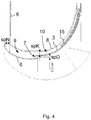
- FIG. 1 is a side sectional view of a fan assembly 1 in a first embodiment with detailed views A and B and an enlarged view ( Fig. 2 ) of the detail shown.
- the fan arrangement 1 comprises a (radial) impeller 2, formed from a flat bottom disk 12, a funnel-shaped cover disk 3 and a blade ring formed from several impeller blades 4 arranged between them.
- the cover disk 3 of the impeller 2 covers the impeller blades 4 and has an axial suction opening 21 and a radial discharge section.
- the fan arrangement 1 Upstream of the impeller 2 in the direction of flow, the fan arrangement 1 comprises a suction nozzle 6 which extends into the suction opening 21 of the impeller 2 in sections in the overlapping section 5.
- the outside diameter of the suction nozzle 6 in the overlap section 5 is smaller than that of the suction opening 21 of the impeller 2, so that a circumferential nozzle gap 7 is formed between the suction nozzle 6 and the cover plate 3 of the impeller 2.
- the impeller 2 and the suction nozzle 6 are surrounded radially on the outside by an outer nozzle 8 in the circumferential direction, with a circumferential radial gap being provided between the outer nozzle 8 and the suction nozzle 6, which forms the inlet nozzle channel 9 running in the direction of flow, and between the outer nozzle 8 and the cover disk 3 of the impeller 2 a circumferential radial gap is provided, which forms the gap channel 10 running in the direction of flow.
- the suction nozzle 6 protrudes in the axial direction beyond the suction-side axial end of the outer nozzle 8 and extends radially outwardly curved in its free axial end section 16, so that a radially outwardly pointing inlet opening 19 is formed between the suction nozzle 6 and the outer nozzle 8.
- the geometric shape of the outer nozzle 8 and the suction nozzle 6 is identical in the area of the inlet opening 19, so that both elements run parallel to one another and form the inlet nozzle channel 9 with an essentially constant gap dimension spN.
- the free one extending into the suction opening 21 of the impeller 2 The end section of the suction nozzle 6 is designed so that it tapers radially outwards towards the cover plate 3 of the impeller 2, so that in the overlap section 5 between the suction nozzle 6 and the impeller 2, the radial nozzle gap dimension spD of the nozzle gap 7 is reduced as viewed in the axial flow direction.
- the flow is directed against the inner wall of the cover plate 3.
- the geometric shape is implemented by a rounding of the suction nozzle 6 and an axial section of the cover disk 3 that runs parallel to the axis of rotation of the impeller 2 and adjoins the suction opening 21.
- the inlet channel 9 ends at the axial end of the cover disk 3, i.e. of the suction opening 21.
- the cover disk 3 divides the inlet channel 9 essentially centrally into a gap channel 10 that adjoins it in the flow direction between the cover disk 3 of the impeller 2 and the outer nozzle 8, which has an essentially constant gap dimension spK. This is achieved by an essentially identical geometric shape of the outer nozzle 8 and cover plate 3 in the area of cover plate 3.
- the outer nozzle 8 On the pressure side, the outer nozzle 8 has a flow guide geometry 11 which is extended beyond the impeller 2 and which extends in the radial and axial direction beyond the blow-out opening of the impeller 2 adjacent to the cover plate 3 of the impeller 2 and the flow blown out by the impeller 2 into the axial direction Direction directs.
- the outer nozzle 8 is shaped in such a way that its flow cross-section, viewed in the direction of flow, is reduced from an initial cross-section to a minimum cross-section and then initially enlarged up to the area of the cover plate 3 and beyond in the area of the flow-guiding geometry 11.
- the nozzle gap 7 between the suction nozzle 6 and the cover plate 3 of the impeller 2 is in the area of the minimum cross-section, i.e. arranged in the area of the maximum negative pressure.
- the total volume flow generated via the impeller 2 on the intake side of the intake nozzle 6 and the outer nozzle 8 in the main volume flow HV flowing through the suction nozzle 6 into the suction opening 21 of the impeller 2 and the secondary volume flow NV flowing through the inlet nozzle channel 9 are divided.
- the secondary volume flow NV is then divided by the cover plate 3 of the impeller 2 and the outer nozzle 8 into the gap volume flow SV flowing through the gap duct 10 and the auxiliary volume flow HiV flowing into the nozzle gap 7 as a pulse flow to the main volume flow HV.
- all of the flows are brought together again.
- Figure 3 is a for execution according to Figure 1 usable, designed as a radial impeller impeller 2 shown in a perspective view.
- a plurality of split blades 15 Arranged on the cover plate 3 are a plurality of split blades 15 designed as radial blades.
- the gap blades 15 are evenly distributed in the circumferential direction over the cover disk 3 and extend at a distance from and between the edge sections of the suction opening 21 and the blow-out section between the bottom disk 12 and cover disk 3.
- FIG. 3 is an alternative embodiment of the fan assembly 1 from FIGS Figures 1 and 2 shown.
- the impeller 2 shown with gap blades 15 is used, which protrude into the gap channel 10 in the direction of the outer nozzle 8.
- the radial extension of the gap blades 15 corresponds to 50% of the gap dimension spK of the gap channel 10.
- an alternative outer nozzle 8 is used, which is elongated in a straight line in the radial direction on the suction side and is designed without a flow guide geometry on the pressure side.
- the suction opening gap dimension spN is greater than the gap channel dimension spK of the gap channel 10 and is greater than the nozzle gap dimension spD of the nozzle gap 7.
- the ratios of the minimum and maximum intake flow cross-section DHmin, DHmax to the maximum impeller outer diameter DA of the impeller 2 are set at 0.3 ⁇ DHmin / DA ⁇ 0.9 and DHmin / DA ⁇ DHmax / DA ⁇ 1.
- the ratio between the nozzle gap dimension spD of the nozzle gap 7 and the impeller outer diameter DA is 0.005.
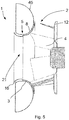
- FIG. 5 a side sectional view of the fan arrangement 1 is shown in an exemplary embodiment in which the outer nozzle 8 forms a diffuser 45. Otherwise, the features of the previous exemplary embodiments also apply in full to the exemplary embodiment according to FIG Fig. 5 .
- the diffuser 45 forms an extension of the nozzle contour at the impeller outlet of the impeller 2 in order to reduce the Carnot losses.
- the nozzle contour is designed in accordance with the contour of the cover disk 3 of the impeller 3, so that the gap duct 10 has an essentially constant throughflow cross-sectional area.
- Split blades 15 can also be used in this embodiment, as described above.
Claims (19)
- Dispositif formant ventilateur (1) aveca. une roue mobile (2), qui présente une ouverture d'aspiration (21) axiale, qui est formée par un disque de recouvrement (3) recouvrant au moins par section des aubes de roue mobile (4),b. une buse d'aspiration (6) en amont de la roue mobile (2) dans le sens d'écoulement, qui s'étend dans l'ouverture d'aspiration de la roue mobile (2) au moins par section dans une section de chevauchement (5), dans lequel une fente de buse (7) circonférentielle est formée entre la buse d'aspiration (6) et le disque de recouvrement (3) de la roue mobile (2),c. une buse extérieure (8), qui est agencée espacée de la roue mobile (2) et de la buse d'aspiration (6) dans la direction radiale et les entourant dans la direction circonférentielle,caractérisé en ce qu'une section d'extrémité libre de la buse d'aspiration (6), qui s'étend dans l'ouverture d'aspiration de la roue mobile (2), s'approche du disque de recouvrement (3) de la roue mobile (2) radialement vers l'extérieur, dans lequel une mesure de fente de buse radiale spD de la fente de buse diminue vu dans le sens d'écoulement axial dans la section de chevauchement (5) entre la buse d'aspiration (6) et la roue mobile (2).i. dans lequel une fente radiale circonférentielle est prévue entre la buse extérieure (8) et la buse d'aspiration (6), qui forme un canal de buse d'entrée (9) s'étendant dans le sens d'écoulement, et dans lequel une fente radiale circonférentielle est prévue entre la buse extérieure (8) et le disque de recouvrement (3) de la roue mobile (2), qui forme un canal de fente (10) s'étendant dans le sens d'écoulement,ii. de sorte qu'un débit volumique total aspiré par la roue mobile (2) peut être divisé par la buse d'aspiration (6) et la buse extérieure (8) en un débit volumique principal s'écoulant à travers la buse d'aspiration (6) dans la roue mobile (2) et un débit volumique secondaire s'écoulant à travers le canal de buse d'entrée (9) et le débit volumique secondaire peut ensuite être divisé par le disque de recouvrement (3) de la roue mobile (2) et la buse extérieure (8) en un débit volumique de fente s'écoulant à travers le canal de fente (10) et un débit volumique auxiliaire entrant dans la fente de buse (7) vers le débit volumique principal,
- Dispositif formant ventilateur selon la revendication 1, caractérisé en ce que la buse d'aspiration (6) s'étend dans la direction axiale au-delà d'une extrémité axiale côté aspiration de la buse extérieure (8) et incurvée radialement vers l'extérieur dans sa section d'extrémité (16) axiale libre, dans lequel une ouverture d'entrée tournée radialement vers l'extérieur est formée entre la buse d'aspiration (6) et le buse extérieure (8).
- Dispositif formant ventilateur selon l'une quelconque des revendications précédentes, caractérisé en ce que le disque de recouvrement (3) s'étend au niveau de sa section axiale adjacente à l'ouverture d'aspiration parallèlement à l'axe de rotation de la roue mobile (2).
- Dispositif formant ventilateur selon l'une quelconque des revendications précédentes, caractérisé en ce qu'une mesure de canal de fente spK du canal de fente (10) est constante dans le sens d'écoulement axial.
- Dispositif formant ventilateur selon l'une quelconque des revendications précédentes, caractérisé en ce qu'une mesure de fente de canal de buse d'entrée spN du canal de fente de buse d'entrée (9) est constante dans le sens d'écoulement axial de l'ouverture d'entrée (19) au disque de recouvrement (3) de la roue mobile (2).
- Dispositif formant ventilateur selon l'une quelconque des revendications précédentes, caractérisé en ce que la buse extérieure (8) présente côté pression une géométrie de conduite d'écoulement (11) prolongée au-delà de la roue mobile (2), qui s'étend dans la direction radiale au-delà d'une ouverture de soufflage de la roue mobile (2) adjacente au disque de recouvrement (3) de la roue mobile (2) et est réalisée pour conduire l'écoulement soufflé par la roue mobile (2).
- Dispositif formant ventilateur selon l'une quelconque des revendications précédentes, caractérisé en ce que la buse extérieure (8) présente côté pression une géométrie de conduite d'écoulement (11) prolongée au-delà de la roue mobile (2), qui couvre une ouverture de soufflage de la roue mobile (2) adjacente au disque de recouvrement (3) de la roue mobile (2) dans la direction axiale et est réalisée pour conduire l'écoulement soufflé par la roue mobile (2).
- Dispositif formant ventilateur selon l'une quelconque des revendications précédentes, caractérisé en ce que des aubes à fente (15) en saillie en direction de la buse extérieure (8) sont prévues sur le disque de recouvrement (3) de la roue mobile (2).
- Dispositif formant ventilateur selon la revendication précédente, caractérisé en ce que les aubes à fente (15) sont réalisées en tant qu'aubes radiales rectilignes ou aubes incurvées vers l'arrière.
- Dispositif formant ventilateur selon l'une quelconque des revendications précédentes 8-9, caractérisé en ce que les aubes à fente (15) sont agencées espacées par rapport à l'ouverture d'aspiration de la roue mobile (2) dans le sens d'écoulement axial.
- Dispositif formant ventilateur selon l'une quelconque des revendications précédentes, caractérisé en ce qu'une section transversale de passage de la buse extérieure (8) vu dans le sens d'écoulement diminue d'une section transversale de début à une section transversale minimum et augmente ensuite à une section transversale de fin, dans lequel la fente de buse (7) est agencée entre la buse d'aspiration (6) et le disque de recouvrement (3) de la roue mobile (2) dans une zone de la section transversale minimum.
- Dispositif formant ventilateur selon l'une quelconque des revendications précédentes 1 à 11, caractérisé en ce qu'un rapport spD/DA entre la mesure de fente de buse spD de la fente de buse et un diamètre extérieur de roue à aube DA de la roue mobile (2) se situe dans une plage de 0,003 à 0,003 ou de 0,005.
- Dispositif formant ventilateur selon l'une quelconque des revendications précédentes 5-12, caractérisé en ce que la mesure de fente d'ouverture d'aspiration spN est supérieure à la mesure de canal de fente spK du canal de fente et supérieure à la mesure de fente de buse spD de la fente de buse, dans lequel spN ≤ 10*spK, spD.
- Dispositif formant ventilateur selon l'une quelconque des revendications précédentes, caractérisé en ce qu'une section transversale de passage DH de la buse d'aspiration (6) diminue dans le sens d'écoulement d'une section transversale de passage d'aspiration maximum DHmax à une section transversale de passage minimum DHmin, dans lequel un rapport de la section transversale de passage d'aspiration minimum et maximum DHmin, DHmax par rapport à un diamètre extérieur de roue mobile DA de la roue mobile (2) se situe dans une plage, tel que DHmin/DA < DHmax/DA < 1.
- Dispositif formant ventilateur selon l'une quelconque des revendications précédentes, caractérisé en ce qu'une section transversale de passage DH de la buse d'aspiration (6) diminue dans la sens d'écoulement d'une section transversale de passage d'aspiration maximum DHMax à une section transversale de passage minimum DHmin, dans lequel un rapport de la section transversale de passage d'aspiration minium DHMin par rapport à un diamètre extérieur de roue mobile DA de la roue mobile (2) se situe dans une plage, tel que 0,3 < DMin/DA < 0,9.
- Dispositif formant ventilateur selon l'une quelconque des revendications précédentes, caractérisé en ce qu'une section transversale de passage de la roue mobile (2) augmente le long du disque de recouvrement (3) dans le sens d'écoulement.
- Dispositif formant ventilateur selon l'une quelconque des revendications précédentes, caractérisé en ce que le débit volumique total est formé de la somme du débit volumique principal s'écoulant de la buse d'aspiration (6) et de la buse extérieure (8) dans le à travers la buse d'aspiration (6) dans la roue mobile (2) et du débit volumique secondaire s'écoulant à travers le canal de buse d'entrée.
- Dispositif formant ventilateur selon l'une quelconque des revendications précédentes, caractérisé en ce que le débit volumique secondaire est formé de la somme du débit volumique de fente s'écoulant à travers le canal de fente et du débit volumique auxiliaire entrant dans la fente de buse (7) vers le débit volumique principal.
- Dispositif formant ventilateur selon l'une quelconque des revendications précédentes, caractérisé en ce que la buse extérieure (8) forme un diffuseur (45) une prolongé au-delà de la roue mobile (2) côté pression.
Applications Claiming Priority (1)
| Application Number | Priority Date | Filing Date | Title |
|---|---|---|---|
| DE102017110642.1A DE102017110642A1 (de) | 2017-05-16 | 2017-05-16 | Gebläseanordnung mit Strömungsteilungsdüse |
Publications (2)
| Publication Number | Publication Date |
|---|---|
| EP3404269A1 EP3404269A1 (fr) | 2018-11-21 |
| EP3404269B1 true EP3404269B1 (fr) | 2020-09-30 |
Family
ID=61381165
Family Applications (1)
| Application Number | Title | Priority Date | Filing Date |
|---|---|---|---|
| EP18159980.4A Active EP3404269B1 (fr) | 2017-05-16 | 2018-03-05 | Dispositif formant ventilateur pourvu de buse de division d'écoulement |
Country Status (4)
| Country | Link |
|---|---|
| US (1) | US10808719B2 (fr) |
| EP (1) | EP3404269B1 (fr) |
| CN (1) | CN206957995U (fr) |
| DE (1) | DE102017110642A1 (fr) |
Families Citing this family (5)
| Publication number | Priority date | Publication date | Assignee | Title |
|---|---|---|---|---|
| DE202019100240U1 (de) | 2019-01-16 | 2019-03-06 | Ebm-Papst Mulfingen Gmbh & Co. Kg | Strömungsleitvorrichtung und Gebläseanordnung mit Strömungsleitvorrichtung |
| DE102019101096A1 (de) | 2019-01-16 | 2020-07-16 | Ebm-Papst Mulfingen Gmbh & Co. Kg | Strömungsleitvorrichtung und Gebläseanordnung mit Strömungsleitvorrichtung |
| US11255348B2 (en) * | 2019-03-14 | 2022-02-22 | Regal Beloit America, Inc. | Blower assembly and methods of assembling the same |
| WO2020211706A1 (fr) * | 2019-04-16 | 2020-10-22 | Atlas Copco (Wuxi) Compressor Co., Ltd. | Dispositif de guidage permettant de diriger un gaz |
| DE102021204491A1 (de) | 2021-05-04 | 2022-11-10 | Ziehl-Abegg Se | Ventilator, insbesondere Radial- oder Diagonalventilator |
Citations (1)
| Publication number | Priority date | Publication date | Assignee | Title |
|---|---|---|---|---|
| DE19713712C1 (de) * | 1997-04-03 | 1998-04-16 | Laengerer & Reich Gmbh & Co | Radialventilator, insbesonders als Lüfter für die Kühlanlage eines Kraftfahrzeuges |
Family Cites Families (10)
| Publication number | Priority date | Publication date | Assignee | Title |
|---|---|---|---|---|
| US1787656A (en) * | 1929-09-21 | 1931-01-06 | American Blower Corp | Induction flow inlet fan |
| AT241674B (de) * | 1962-10-16 | 1965-08-10 | Theodor Dr Ing Helmbold | Axialgebläse |
| US5525036A (en) * | 1991-11-29 | 1996-06-11 | Goldstar Co., Ltd. | Suction structure of a sirocco fan housing |
| DE4227901C2 (de) * | 1992-08-22 | 2000-11-09 | Behr Gmbh & Co | Lüfteranordnung, insbesondere für die Kühlung von Kraftfahrzeugmotoren |
| SE515524C2 (sv) * | 1992-10-01 | 2001-08-20 | Flaekt Ab | Inloppsklocka för centrifugalfläktar |
| US5478201A (en) * | 1994-06-13 | 1995-12-26 | Carrier Corporation | Centrifugal fan inlet orifice and impeller assembly |
| DE4431840A1 (de) * | 1994-09-07 | 1996-03-14 | Behr Gmbh & Co | Lüfter für eine Kühlanlage eines Kraftfahrzeugs |
| EP1473465B2 (fr) * | 2003-04-30 | 2018-08-01 | Holset Engineering Company Limited | Compresseur |
| US9086073B2 (en) * | 2012-02-10 | 2015-07-21 | Halla Visteon Climate Control Corporation | Blower assembly |
| JP6001707B2 (ja) * | 2015-02-25 | 2016-10-05 | 株式会社オティックス | 過給機用のコンプレッサハウジング |
-
2017
- 2017-05-16 DE DE102017110642.1A patent/DE102017110642A1/de not_active Withdrawn
- 2017-07-18 CN CN201720871134.XU patent/CN206957995U/zh active Active
-
2018
- 2018-03-05 EP EP18159980.4A patent/EP3404269B1/fr active Active
- 2018-04-18 US US15/956,272 patent/US10808719B2/en active Active
Patent Citations (1)
| Publication number | Priority date | Publication date | Assignee | Title |
|---|---|---|---|---|
| DE19713712C1 (de) * | 1997-04-03 | 1998-04-16 | Laengerer & Reich Gmbh & Co | Radialventilator, insbesonders als Lüfter für die Kühlanlage eines Kraftfahrzeuges |
Also Published As
| Publication number | Publication date |
|---|---|
| EP3404269A1 (fr) | 2018-11-21 |
| US10808719B2 (en) | 2020-10-20 |
| DE102017110642A1 (de) | 2018-11-22 |
| US20180335048A1 (en) | 2018-11-22 |
| CN206957995U (zh) | 2018-02-02 |
Similar Documents
| Publication | Publication Date | Title |
|---|---|---|
| EP3404269B1 (fr) | Dispositif formant ventilateur pourvu de buse de division d'écoulement | |
| EP2418389B1 (fr) | Hélice pour un ventilateur | |
| EP2696029B1 (fr) | Grille d'aube avec définition de contour de la paroi latérale et turbomachine | |
| DE102009052142B3 (de) | Axialverdichter | |
| DE112013002698T5 (de) | Luftgebläse | |
| EP3325812B1 (fr) | Machine à canal latéral (compresseur, pompe à vide, ou ventilateur) avec un conduit de purge dans le barrage | |
| EP0903468A1 (fr) | Bandage annulaire pour turbine axiale | |
| DE1428191A1 (de) | Kreiselgeblaese | |
| DE102009006652B4 (de) | Seitenkanalgebläse, insbesondere Sekundärluftgebläse für eine Verbrennungskraftmaschine | |
| DE3238972C2 (de) | Horizontal geteiltes Gehäuse einer Strömungsarbeitsmaschine für Gase oder Dämpfe | |
| EP2746534B1 (fr) | Étage statorique et/ou rotorique de turbomachine, et turbine à gaz associée | |
| EP3051142A1 (fr) | Compresseur axial de turbine a gaz | |
| WO2016110373A1 (fr) | Soufflante à canal latéral pour un moteur à combustion interne | |
| EP3256732B1 (fr) | Roue pour un ventilateur et ventilateur | |
| DE102011013841B4 (de) | Radialventilatorrad und Radialventilator | |
| EP1914402B1 (fr) | Ventilateur axial et procédé destiné à éviter un flux de recirculation | |
| DE202017102950U1 (de) | Gebläseanordnung mit Strömungsteilungsdüse | |
| DE102005012815A1 (de) | Gehäuse, Laufrad und Radialgebläse mit einem Gehäuse und einem Laufrad | |
| WO2017194272A1 (fr) | Étage de retour pour un turbocompresseur radial et turbocompresseur radial | |
| EP3114354B1 (fr) | Roue de ventilateur pour ventilateur axial | |
| DE102015014900A1 (de) | Radialturbinengehäuse | |
| WO2019034740A1 (fr) | Diffuseur pour compresseur radial | |
| EP3375977A1 (fr) | Contournage d'une plate-forme de grille d'aube | |
| EP1582750B1 (fr) | Boitier et soufflante avec un boitier et une roue | |
| WO2021083442A1 (fr) | Ensemble aube directrice de turbomachine |
Legal Events
| Date | Code | Title | Description |
|---|---|---|---|
| PUAI | Public reference made under article 153(3) epc to a published international application that has entered the european phase |
Free format text: ORIGINAL CODE: 0009012 |
|
| STAA | Information on the status of an ep patent application or granted ep patent |
Free format text: STATUS: THE APPLICATION HAS BEEN PUBLISHED |
|
| AK | Designated contracting states |
Kind code of ref document: A1 Designated state(s): AL AT BE BG CH CY CZ DE DK EE ES FI FR GB GR HR HU IE IS IT LI LT LU LV MC MK MT NL NO PL PT RO RS SE SI SK SM TR |
|
| AX | Request for extension of the european patent |
Extension state: BA ME |
|
| STAA | Information on the status of an ep patent application or granted ep patent |
Free format text: STATUS: REQUEST FOR EXAMINATION WAS MADE |
|
| 17P | Request for examination filed |
Effective date: 20190410 |
|
| RBV | Designated contracting states (corrected) |
Designated state(s): AL AT BE BG CH CY CZ DE DK EE ES FI FR GB GR HR HU IE IS IT LI LT LU LV MC MK MT NL NO PL PT RO RS SE SI SK SM TR |
|
| GRAP | Despatch of communication of intention to grant a patent |
Free format text: ORIGINAL CODE: EPIDOSNIGR1 |
|
| STAA | Information on the status of an ep patent application or granted ep patent |
Free format text: STATUS: GRANT OF PATENT IS INTENDED |
|
| RIC1 | Information provided on ipc code assigned before grant |
Ipc: F04D 29/42 20060101ALI20200520BHEP Ipc: F04D 29/16 20060101AFI20200520BHEP Ipc: F04D 29/68 20060101ALI20200520BHEP |
|
| INTG | Intention to grant announced |
Effective date: 20200623 |
|
| GRAS | Grant fee paid |
Free format text: ORIGINAL CODE: EPIDOSNIGR3 |
|
| GRAA | (expected) grant |
Free format text: ORIGINAL CODE: 0009210 |
|
| STAA | Information on the status of an ep patent application or granted ep patent |
Free format text: STATUS: THE PATENT HAS BEEN GRANTED |
|
| AK | Designated contracting states |
Kind code of ref document: B1 Designated state(s): AL AT BE BG CH CY CZ DE DK EE ES FI FR GB GR HR HU IE IS IT LI LT LU LV MC MK MT NL NO PL PT RO RS SE SI SK SM TR |
|
| REG | Reference to a national code |
Ref country code: CH Ref legal event code: EP Ref country code: GB Ref legal event code: FG4D Free format text: NOT ENGLISH |
|
| REG | Reference to a national code |
Ref country code: DE Ref legal event code: R096 Ref document number: 502018002570 Country of ref document: DE Ref country code: AT Ref legal event code: REF Ref document number: 1319075 Country of ref document: AT Kind code of ref document: T Effective date: 20201015 |
|
| REG | Reference to a national code |
Ref country code: IE Ref legal event code: FG4D Free format text: LANGUAGE OF EP DOCUMENT: GERMAN |
|
| REG | Reference to a national code |
Ref country code: NL Ref legal event code: FP |
|
| REG | Reference to a national code |
Ref country code: SE Ref legal event code: TRGR |
|
| PG25 | Lapsed in a contracting state [announced via postgrant information from national office to epo] |
Ref country code: FI Free format text: LAPSE BECAUSE OF FAILURE TO SUBMIT A TRANSLATION OF THE DESCRIPTION OR TO PAY THE FEE WITHIN THE PRESCRIBED TIME-LIMIT Effective date: 20200930 Ref country code: GR Free format text: LAPSE BECAUSE OF FAILURE TO SUBMIT A TRANSLATION OF THE DESCRIPTION OR TO PAY THE FEE WITHIN THE PRESCRIBED TIME-LIMIT Effective date: 20201231 Ref country code: NO Free format text: LAPSE BECAUSE OF FAILURE TO SUBMIT A TRANSLATION OF THE DESCRIPTION OR TO PAY THE FEE WITHIN THE PRESCRIBED TIME-LIMIT Effective date: 20201230 Ref country code: BG Free format text: LAPSE BECAUSE OF FAILURE TO SUBMIT A TRANSLATION OF THE DESCRIPTION OR TO PAY THE FEE WITHIN THE PRESCRIBED TIME-LIMIT Effective date: 20201230 Ref country code: HR Free format text: LAPSE BECAUSE OF FAILURE TO SUBMIT A TRANSLATION OF THE DESCRIPTION OR TO PAY THE FEE WITHIN THE PRESCRIBED TIME-LIMIT Effective date: 20200930 |
|
| PG25 | Lapsed in a contracting state [announced via postgrant information from national office to epo] |
Ref country code: LV Free format text: LAPSE BECAUSE OF FAILURE TO SUBMIT A TRANSLATION OF THE DESCRIPTION OR TO PAY THE FEE WITHIN THE PRESCRIBED TIME-LIMIT Effective date: 20200930 Ref country code: RS Free format text: LAPSE BECAUSE OF FAILURE TO SUBMIT A TRANSLATION OF THE DESCRIPTION OR TO PAY THE FEE WITHIN THE PRESCRIBED TIME-LIMIT Effective date: 20200930 |
|
| REG | Reference to a national code |
Ref country code: LT Ref legal event code: MG4D |
|
| PG25 | Lapsed in a contracting state [announced via postgrant information from national office to epo] |
Ref country code: LT Free format text: LAPSE BECAUSE OF FAILURE TO SUBMIT A TRANSLATION OF THE DESCRIPTION OR TO PAY THE FEE WITHIN THE PRESCRIBED TIME-LIMIT Effective date: 20200930 Ref country code: EE Free format text: LAPSE BECAUSE OF FAILURE TO SUBMIT A TRANSLATION OF THE DESCRIPTION OR TO PAY THE FEE WITHIN THE PRESCRIBED TIME-LIMIT Effective date: 20200930 Ref country code: PT Free format text: LAPSE BECAUSE OF FAILURE TO SUBMIT A TRANSLATION OF THE DESCRIPTION OR TO PAY THE FEE WITHIN THE PRESCRIBED TIME-LIMIT Effective date: 20210201 Ref country code: RO Free format text: LAPSE BECAUSE OF FAILURE TO SUBMIT A TRANSLATION OF THE DESCRIPTION OR TO PAY THE FEE WITHIN THE PRESCRIBED TIME-LIMIT Effective date: 20200930 Ref country code: SM Free format text: LAPSE BECAUSE OF FAILURE TO SUBMIT A TRANSLATION OF THE DESCRIPTION OR TO PAY THE FEE WITHIN THE PRESCRIBED TIME-LIMIT Effective date: 20200930 |
|
| PG25 | Lapsed in a contracting state [announced via postgrant information from national office to epo] |
Ref country code: IS Free format text: LAPSE BECAUSE OF FAILURE TO SUBMIT A TRANSLATION OF THE DESCRIPTION OR TO PAY THE FEE WITHIN THE PRESCRIBED TIME-LIMIT Effective date: 20210130 Ref country code: PL Free format text: LAPSE BECAUSE OF FAILURE TO SUBMIT A TRANSLATION OF THE DESCRIPTION OR TO PAY THE FEE WITHIN THE PRESCRIBED TIME-LIMIT Effective date: 20200930 Ref country code: AL Free format text: LAPSE BECAUSE OF FAILURE TO SUBMIT A TRANSLATION OF THE DESCRIPTION OR TO PAY THE FEE WITHIN THE PRESCRIBED TIME-LIMIT Effective date: 20200930 Ref country code: ES Free format text: LAPSE BECAUSE OF FAILURE TO SUBMIT A TRANSLATION OF THE DESCRIPTION OR TO PAY THE FEE WITHIN THE PRESCRIBED TIME-LIMIT Effective date: 20200930 |
|
| PG25 | Lapsed in a contracting state [announced via postgrant information from national office to epo] |
Ref country code: SK Free format text: LAPSE BECAUSE OF FAILURE TO SUBMIT A TRANSLATION OF THE DESCRIPTION OR TO PAY THE FEE WITHIN THE PRESCRIBED TIME-LIMIT Effective date: 20200930 |
|
| REG | Reference to a national code |
Ref country code: DE Ref legal event code: R097 Ref document number: 502018002570 Country of ref document: DE |
|
| PLBE | No opposition filed within time limit |
Free format text: ORIGINAL CODE: 0009261 |
|
| STAA | Information on the status of an ep patent application or granted ep patent |
Free format text: STATUS: NO OPPOSITION FILED WITHIN TIME LIMIT |
|
| PG25 | Lapsed in a contracting state [announced via postgrant information from national office to epo] |
Ref country code: DK Free format text: LAPSE BECAUSE OF FAILURE TO SUBMIT A TRANSLATION OF THE DESCRIPTION OR TO PAY THE FEE WITHIN THE PRESCRIBED TIME-LIMIT Effective date: 20200930 |
|
| 26N | No opposition filed |
Effective date: 20210701 |
|
| PG25 | Lapsed in a contracting state [announced via postgrant information from national office to epo] |
Ref country code: MC Free format text: LAPSE BECAUSE OF FAILURE TO SUBMIT A TRANSLATION OF THE DESCRIPTION OR TO PAY THE FEE WITHIN THE PRESCRIBED TIME-LIMIT Effective date: 20200930 |
|
| REG | Reference to a national code |
Ref country code: CH Ref legal event code: PL |
|
| PG25 | Lapsed in a contracting state [announced via postgrant information from national office to epo] |
Ref country code: SI Free format text: LAPSE BECAUSE OF FAILURE TO SUBMIT A TRANSLATION OF THE DESCRIPTION OR TO PAY THE FEE WITHIN THE PRESCRIBED TIME-LIMIT Effective date: 20200930 |
|
| REG | Reference to a national code |
Ref country code: BE Ref legal event code: MM Effective date: 20210331 |
|
| PG25 | Lapsed in a contracting state [announced via postgrant information from national office to epo] |
Ref country code: LI Free format text: LAPSE BECAUSE OF NON-PAYMENT OF DUE FEES Effective date: 20210331 Ref country code: LU Free format text: LAPSE BECAUSE OF NON-PAYMENT OF DUE FEES Effective date: 20210305 Ref country code: CH Free format text: LAPSE BECAUSE OF NON-PAYMENT OF DUE FEES Effective date: 20210331 Ref country code: IE Free format text: LAPSE BECAUSE OF NON-PAYMENT OF DUE FEES Effective date: 20210305 |
|
| PG25 | Lapsed in a contracting state [announced via postgrant information from national office to epo] |
Ref country code: IS Free format text: LAPSE BECAUSE OF FAILURE TO SUBMIT A TRANSLATION OF THE DESCRIPTION OR TO PAY THE FEE WITHIN THE PRESCRIBED TIME-LIMIT Effective date: 20210130 |
|
| PG25 | Lapsed in a contracting state [announced via postgrant information from national office to epo] |
Ref country code: BE Free format text: LAPSE BECAUSE OF NON-PAYMENT OF DUE FEES Effective date: 20210331 |
|
| PGFP | Annual fee paid to national office [announced via postgrant information from national office to epo] |
Ref country code: FR Payment date: 20230320 Year of fee payment: 6 Ref country code: CZ Payment date: 20230221 Year of fee payment: 6 Ref country code: AT Payment date: 20230317 Year of fee payment: 6 |
|
| PGFP | Annual fee paid to national office [announced via postgrant information from national office to epo] |
Ref country code: SE Payment date: 20230315 Year of fee payment: 6 |
|
| P01 | Opt-out of the competence of the unified patent court (upc) registered |
Effective date: 20230522 |
|
| PG25 | Lapsed in a contracting state [announced via postgrant information from national office to epo] |
Ref country code: CY Free format text: LAPSE BECAUSE OF FAILURE TO SUBMIT A TRANSLATION OF THE DESCRIPTION OR TO PAY THE FEE WITHIN THE PRESCRIBED TIME-LIMIT Effective date: 20200930 |
|
| PG25 | Lapsed in a contracting state [announced via postgrant information from national office to epo] |
Ref country code: HU Free format text: LAPSE BECAUSE OF FAILURE TO SUBMIT A TRANSLATION OF THE DESCRIPTION OR TO PAY THE FEE WITHIN THE PRESCRIBED TIME-LIMIT; INVALID AB INITIO Effective date: 20180305 |
|
| PGFP | Annual fee paid to national office [announced via postgrant information from national office to epo] |
Ref country code: IT Payment date: 20230331 Year of fee payment: 6 |
|
| PGFP | Annual fee paid to national office [announced via postgrant information from national office to epo] |
Ref country code: NL Payment date: 20240320 Year of fee payment: 7 |
|
| PGFP | Annual fee paid to national office [announced via postgrant information from national office to epo] |
Ref country code: AT Payment date: 20240318 Year of fee payment: 7 |
|
| PG25 | Lapsed in a contracting state [announced via postgrant information from national office to epo] |
Ref country code: MK Free format text: LAPSE BECAUSE OF FAILURE TO SUBMIT A TRANSLATION OF THE DESCRIPTION OR TO PAY THE FEE WITHIN THE PRESCRIBED TIME-LIMIT Effective date: 20200930 |
|
| PGFP | Annual fee paid to national office [announced via postgrant information from national office to epo] |
Ref country code: DE Payment date: 20240321 Year of fee payment: 7 Ref country code: CZ Payment date: 20240223 Year of fee payment: 7 Ref country code: GB Payment date: 20240322 Year of fee payment: 7 |