EP3404156B1 - Herstellungsverfahren für dichtband - Google Patents
Herstellungsverfahren für dichtband Download PDFInfo
- Publication number
- EP3404156B1 EP3404156B1 EP18172030.1A EP18172030A EP3404156B1 EP 3404156 B1 EP3404156 B1 EP 3404156B1 EP 18172030 A EP18172030 A EP 18172030A EP 3404156 B1 EP3404156 B1 EP 3404156B1
- Authority
- EP
- European Patent Office
- Prior art keywords
- foam
- coating
- strips
- adhesive
- self
- Prior art date
- Legal status (The legal status is an assumption and is not a legal conclusion. Google has not performed a legal analysis and makes no representation as to the accuracy of the status listed.)
- Active
Links
Images
Classifications
-
- E—FIXED CONSTRUCTIONS
- E04—BUILDING
- E04B—GENERAL BUILDING CONSTRUCTIONS; WALLS, e.g. PARTITIONS; ROOFS; FLOORS; CEILINGS; INSULATION OR OTHER PROTECTION OF BUILDINGS
- E04B1/00—Constructions in general; Structures which are not restricted either to walls, e.g. partitions, or floors or ceilings or roofs
- E04B1/62—Insulation or other protection; Elements or use of specified material therefor
- E04B1/66—Sealings
- E04B1/68—Sealings of joints, e.g. expansion joints
- E04B1/6812—Compressable seals of solid form
-
- E—FIXED CONSTRUCTIONS
- E06—DOORS, WINDOWS, SHUTTERS, OR ROLLER BLINDS IN GENERAL; LADDERS
- E06B—FIXED OR MOVABLE CLOSURES FOR OPENINGS IN BUILDINGS, VEHICLES, FENCES OR LIKE ENCLOSURES IN GENERAL, e.g. DOORS, WINDOWS, BLINDS, GATES
- E06B1/00—Border constructions of openings in walls, floors, or ceilings; Frames to be rigidly mounted in such openings
- E06B1/62—Tightening or covering joints between the border of openings and the frame or between contiguous frames
- E06B2001/626—Tightening or covering joints between the border of openings and the frame or between contiguous frames comprising expanding foam strips
Definitions
- the present invention relates to a method of manufacturing a sealing tape.
- a wide variety of sealing tapes for a wide variety of applications are known.
- sealing tapes are also known which have a coating on a foam carrier, which is intended to reduce vapor diffusion, for example.
- Various procedures for the production of such sealing tapes are known from the prior art. For example, it is known that a foam carrier is cut open and a film is introduced into a cut area.
- a method for producing a roll of sealing tape in which a first foam strip, which is provided with at least one barrier layer on at least one of its side flanks, is brought together with a second foam strip in such a way that a foam barrier layer web is formed, in which the at least one Barrier layer is arranged between the two foam strips.
- the present invention is therefore based on the object of providing a method which makes it possible to produce such sealing tapes in a simpler manner. This object is achieved according to the invention by the subject matter of the independent patent claim.
- a foam carrier is first made available and this is transported at least temporarily in a predetermined transport direction.
- a coating is applied to a first surface of the foam backing.
- the foam backing is cut into at least two and preferably a large number of strips. At least some of the cut strips are shifted and/or staggered with respect to one another in such a way that their side surfaces, along which the cuts were made, become accessible for the application of the self-adhesive.
- a self-adhesive is attached to another surface of the individual strips.
- each of the cut strips has a coating on one surface and self-adhesive on another surface. These two surfaces are advantageously perpendicular to one another. In a further preferred method, these strips each have a substantially rectangular cross-section.
- the coating is preferably built on or attached to the foam carrier without gaps and/or continuously. Said cuts also advantageously extend in a transport direction of the foam carrier. However, it is possible that the foam carrier is at rest when the cuts are made, for example lying on a shelf.
- the foam carrier extends in the transport direction and in a width direction perpendicular thereto.
- the Foam carrier extend in said width direction, for example, by one meter.
- the coating is a flexible coating.
- this is a thin coating.
- This particularly preferably has a thickness of between 10 ⁇ m and 1 mm, preferably between 50 ⁇ m and 200 ⁇ m.
- the coating is particularly preferably selected from a group of coatings which contains plastic materials.
- a coating is first applied to the first surface of the foam backing, the foam is then cut, and then the self-adhesive is applied.
- an elastic and/or flexible foil and/or lamination or coating is that it is easier to apply longitudinal edges of this layer to joint flanks, the so-called flank closure.
- the lamination or the coating should meet these requirements.
- these coatings it would also be possible or additionally possible for these coatings to be UV-resistant, waterproof, impervious to driving rain, paintable and/or plasterable.
- the coating is a film coating or film lamination.
- This coating preferably consists of a plastic which is selected from a group of plastics which contains PU, PP, PE, PVC, PET, TPU and the like.
- metallized plastics can also be used.
- the coating it would also be possible to use a metal foil as the coating.
- nonwovens could also be used, which could be used with or without impregnation.
- elastic membranes such as EPDM foils could also be used.
- the coating it would also be conceivable for the coating to be a lamination with a further layer of foam. This further foam can be available in an impregnated or non-impregnated version. A foam can also be selected for this additional foam from a group of foams which contains PU, PP, PE, PVC, TPU, EPDM and the like.
- adhesives or sealants could be used, for example, which contain in particular, but not exclusively, silicones, PU, acrylates, hybrid sealants, PVAC and the like. Modifications of these materials could also be used.
- the coating is attached to the foam by means of a foil and in particular a hot-melt foil.
- a foil and in particular a hot-melt foil It is possible, for example, for an impregnated foam sheet to leave a dryer.
- a hotmelt film and a coating or laminating film are then unrolled from each supply roll and placed on the foam.
- This package can then run or be transported through a laminating system with which a predetermined temperature, for example a temperature between 80 and 200 °, preferably between 100 and 180 ° and particularly preferably between 120 and 160 is.
- the hotmelt film between the foam and the laminating film or the coating melts and in this way the composite of the foam and the film is produced.
- adhesion it would also be possible for adhesion to take place using a self-adhesive film or an adhesive mass between a foam material and the film.
- the foam web is coated not just on one side but on both sides, and in particular on two opposite sides. It is then conceivable that this upper and lower side of the preliminary product of the foam web result in an inner and outer side of the sealing tape end product.
- the advantage of such a double-sided lamination or the application of a coating on both sides could be coatings with different properties specifically tailored to the requirements of the end product. It would be conceivable here, for example, to have a UV-stable coating and a vapor-permeable coating on an outside and, on the other hand, a vapor-tight or vapor-retardant and airtight coating on the inside.
- the foam carrier is preferably transported continuously. However, clocked transport would also be conceivable. It is possible that the foam backing itself is stationary while the cuts are being made and instead the cutting blades move and in particular move in a predetermined longitudinal direction of the foam backing and in particular in the direction in which the foam backing would otherwise, i.e. if the cuts are not made , is transported.
- the knives can, for example, be rotating knives or knife discs.
- the foam backing is an impregnated foam backing, more preferably a foam backing impregnated for delayed recovery.
- the foam backing is also advantageously a dried foam backing and particularly preferably a foam backing which has been impregnated and dried prior to processing.
- aqueous dispersions are used as impregnates.
- Aqueous dispersions with acrylate binders are preferably used.
- other impregnations could also be used, in particular adhesives or sealants in different liquid media. These adhesives or sealants can be, for example, acrylates, bitumen, polyurethanes, resins and the like.
- liquid media Water with or without additives or else organic solvents can be considered as liquid media, for example.
- the foam carrier can be, for example, a polyurethane foam.
- This foam preferably has a bulk density of between 5 and 100 kg/m 3 , preferably between 10 and 80 kg/m 3 , preferably between 10 and 60 kg/m 3 , preferably between 15 and 50 kg/m 3 and particularly preferably between 20 and 40 kg/m 3 .
- the foam preferably has a compression hardness of between 1 kPa and 8 kPa, preferably between 2 kPa and 6 kPa, preferably between 3 kPa and 4 kPa.
- the air permeability of the foam is between 100 and 10,000 l/m 3 /s, preferably between 200 and 5,000 l/(m 3 *s), preferably between 200 and 2,000 l/(m 3 *s) , preferably between 300 and 900 l/(m 3 *s).
- the strips are preferably cut to length.
- the cutting to length is usually and preferably done as a web, from which the strips - already cut to length - are then cut.
- the first coating is applied to an upward or downward facing surface of the foam backing.
- the strips are not rotated after cutting.
- a variant of the method can be used here, in which the self-adhesive is guided laterally to the stiffeners and preferably individual rolls are compressed and rolled up lying flat.
- the individual strips are first cut and then preferably shifted relative to one another in a direction perpendicular to the transport direction, so that in particular the side surfaces of these strips are also accessible for the attachment of a self-adhesive. It would be conceivable here for the strips to be offset relative to one another in a vertical direction, for example alternately offset upwards and downwards.
- At least some of the cut strips are shifted relative to one another in such a way that their side faces, in which it is in particular the surfaces along which the cuts have been made that become accessible for the application of the self-adhesive.
- a stub shaft can preferably be used for each individual roller, with a separate drive for the stub shaft preferably being provided in each case.
- the cut strips are at least partially rolled up, the strips preferably being compressed in at least one direction during this rolling up.
- Compression preferably takes place to not less than 20% of the initial height of the foam strip, preferably to not less than 15% of the initial height, preferably to not less than 10% and particularly preferably to not less than 7% of the initial height.
- the latter means that the foam strip is compressed by 93%.
- the individual strips are rolled up with respect to a horizontal roll axis.
- the strips for applying the self-adhesive are guided onto a self-adhesive tape and, in particular, compressed.
- both the application of the self-adhesive and the compression of the foam strips are preferably carried out in a common step.
- the expanded strips pass between two compression rollers. Between these compression rollers, the strips are pressed to an intended degree of compression (e.g. the 11 to 15% mentioned above).
- a self-adhesive such as a self-adhesive strip, is fed from a supply roll and adhered and pressed to the compressed foam. This combination is preferably then wound onto a core and secured in compressed form with one or more wraps of adhesive tape.
- the foam web it would be possible for the foam web to be cut in a fully expanded state or also in a partially compressed state.
- the laminated web ie the foam web already provided with the coating
- This strip can follow the principle of a bread slicer.
- the cutting tool which can be, for example, a circular knife, a saw or an oscillating cutting edge, preferably moves around the workpiece, ie the foam material remains in place.
- a pressure device such as a pressure beam or pressure rollers.
- the applied coating is preferably airtight. It would also be conceivable that this airtight lamination also makes it possible to fix the foam sheet by means of a vacuum.
- the already coated web is compressed and docked without self-adhesive.
- rolls can be cut off in a desired width from this dock. These rolls are preferentially opened by further processing and the belts can expand.
- the self-adhesive is then applied as described in more detail above.
- the strips are cut in such a way that, in a substantially fully expanded state, the strips have an at least square cross-section, ie a width of the strip is greater than its height.
- the width indicates the side on the self-adhesive or the side opposite it.
- the foam web is first cut and then the coating is applied to the individual strips.
- a coating could be applied to the strips prior to compression onto the self-adhesive film. It would also be conceivable that the coating is applied laterally but also above, below or below and above.
- the self-adhesive tape is preferably a double-sided adhesive tape.
- This double-sided adhesive tape can initially also be equipped with a liner on the side facing away from the foam. In this case it is possible that the combination of the foam backing, the self-adhesive and the liner will roll up.
- the tape In a state wound up on the roll, the tape thus has a coating on the outside.
- This coating is preferably a film lamination or a sealant.
- a coating is applied to a second surface of the foam carrier, this second surface being different from the first surface and in particular being opposite the first surface.
- the present disclosure is also directed to a sealing tape made up as a roll of sealing tape, which extends in a first longitudinal direction and in a width direction perpendicular to this first longitudinal direction, this sealing tape having a first surface which extends in this longitudinal direction and the width direction and a second Has surface, which is opposite to the first surface, wherein an adhesive layer is arranged on one of these two surfaces.
- the sealing tape has a third surface which extends in the longitudinal direction and in a thickness direction of the tape and a fourth surface which is opposite to the third surface and which also extends in the longitudinal direction and the thickness direction, the third surface or a coating is arranged on the fourth or the third and fourth surface. This is preferably a coating of the type described above.
- sealing strip is preferably manufactured using a method of the type described above (not claimed).
- the sealing tape is rolled up in a state compressed in the thickness direction. Therefore, preferably the third and fourth surfaces each face outwards or are sides or faces of the roll of sealing tape in the rolled-up state.
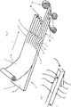
- FIG. 1 shows a schematic representation to illustrate a procedure not according to the invention.
- a foam carrier 2 with a surface 2c is transported in a transport direction T in an area B1.
- This transport direction also corresponds to the longitudinal direction of the sealing tape to be produced later.
- On the foam backing a coating 14 is applied.
- This coating 14 can be a surface element which is unwound from a roll.
- This coating 14 has a surface 14a.
- a multiplicity of cuts S are made in the foam carrier 2, which has already been provided with the coating 14. These cuts are parallel to one another and also extend in the transport direction T. These cuts produce a multiplicity of strips 22, 24, 26 which are parallel to one another and which extend in the transport direction T.
- these individual strips are each rotated counterclockwise by 90°, so that the surfaces provided with the coating 14 each point to the right, viewed in the direction of transport. If corresponding coatings are applied both to the surface 2c and to the opposite surface 2d, a corresponding coating would also be present after the rotation on the left-hand surface viewed in the transport direction.
- an adhesive layer 12 is attached to the underside of the individual cut strips. It is possible that the strips (not shown) are already compressed onto these adhesive layers.
- the individual sealing tapes are then rolled up (not shown) onto a sealing tape roll 20.
- Reference numerals 22b and 24b identify two surfaces on which the coating is arranged.
- FIG. 2 shows a schematic representation of a sealing tape 1 in an unrolled state.
- This sealing strip has a longitudinal direction L, as well as a width direction B perpendicular to this longitudinal direction L and a thickness direction D.
- Reference number 2c refers to a surface of the sealing strip on which a coating 14 is arranged.
- a coating could also be arranged on the rear surface 2d.
- the coating 14 on the side surface 2c and the optionally present coating on the side surface 2d preferably differ from one another in at least one physical property.
- Numeral 12 denotes an adhesive layer which is arranged on a downwardly facing surface 2b.
- the surface 2a is neither coated nor provided with an adhesive layer.
Landscapes
- Engineering & Computer Science (AREA)
- Architecture (AREA)
- Civil Engineering (AREA)
- Structural Engineering (AREA)
- Physics & Mathematics (AREA)
- Electromagnetism (AREA)
- Adhesive Tapes (AREA)
Description
- Die vorliegende Erfindung bezieht sich auf ein Verfahren zum Herstellen eines Dichtbandes. .Aus dem Stand der Technik sind unterschiedlichste Dichtbänder für unterschiedlichste Anwendungsbereiche bekannt. So sind auch Dichtbänder bekannt, welche auf einem Schaumstoffträger eine Beschichtung aufweisen, welche beispielsweise die Dampfdiffusion reduzieren soll. Aus dem Stand der Technik sind diverse Vorgehensweisen für die Herstellung derartiger Dichtbänder bekannt. So ist es beispielsweise bekannt, dass ein Schaumstoffträger aufgeschnitten wird und in einen Schnittbereich eine Folie eingebracht wird.
- Ein Beispiel für ein derartiges Verfahren und eine entsprechende Vorrichtung ist aus
DE 10 2015 116 667 A1 bekannt. Dabei erfolgt das Aufschneiden des Schaumstoffträgers während dessen Transports entlang einer vorgegebenen Transportrichtung. - Eine alternative Verfahrensführung ist aus
EP 2 107 176 A1 bekannt. Gemäß des darin beschriebenen Verfahrens erfolgt das Schneiden des Schaumstoffträgers beziehungsweise der Schaumstoffbahn nach dem Aufwickeln auf eine breite Rolle. Anschließend muss das Dichtband von jeder der dabei entstehenden Dichtbandrollen abgewickelt werden, um dann auf mindestens einer Seitenfläche mit einer flexiblen, folienartigen Beschichtung versehen zu werden. - Diese Vorgehensweisen sind jedoch relativ aufwändig.
- Aus
EP 2 990 552 A1 ist ein Verfahren zur Herstellung einer Dichtbandrolle bekannt, bei welchem ein erster Schaumstoffstreifen, der an mindestens einer seiner Seitenflanken mit mindestens einer Sperrschicht versehen ist, mit einem zweiten Schaumstoffstreifen derart zusammengeführt wird, dass eine Schaumstoff-Sperrschicht-Bahn entsteht, bei der die mindestens eine Sperrschicht zwischen den beiden Schaumstoffstreifen angeordnet ist. - Der vorliegenden Erfindung liegt daher die Aufgabe zugrunde, ein Verfahren zur Verfügung zu stellen, welches in einfacherer Weise eine Herstellung derartiger Dichtbänder ermöglicht. Diese Aufgabe wird erfindungsgemäß durch den Gegenstand des unabhängigen Patentanspruchs gelöst.
- Bei einem erfindungsgemäßen Verfahren zum Herstellen eines Dichtbandes wird zunächst ein Schaumstoffträger zur Verfügung gestellt und dieser wenigstens zeitweise in einer vorgegebenen Transportrichtung transportiert. In einem weiteren Verfahrensschritt wird an eine erste Oberfläche des Schaumstoffträgers eine Beschichtung angebracht. In einem weiteren Verfahrensschritt wird der Schaumstoffträger in wenigstens zwei und bevorzugt eine Vielzahl von Streifen geschnitten. Wenigstens einiger der geschnittenen Streifen werden derart bezüglich einander verschoben und/oder versetzt, dass deren Seitenflächen, entlang derer die Schnitte erfolgt sind, für die Anbringung der Selbstklebung zugänglich werden. Weiterhin wird an einer weiteren Oberfläche der einzelnen Streifen eine Selbstklebung angebracht.
- Auf diese Weise wird erreicht, dass jeder der geschnittenen Streifen an einer Oberfläche eine Beschichtung und an einer weiteren Oberfläche eine Selbstklebung aufweist. Vorteilhaft stehen dabei diese beiden Flächen senkrecht zueinander. Bei einem weiteren bevorzugten Verfahren weisen diese Streifen jeweils einen im Wesentlichen rechteckigen Querschnitt auf.
- Bevorzugt wird die Beschichtung lückenlos und/oder durchgehend an die Schaumstoffträger angebaut bzw. angebracht. Vorteilhaft erstrecken sich die besagten Schnitte ebenfalls in einer Transportrichtung des Schaumstoffträgers. Dabei ist es jedoch möglich, dass der Schaumstoffträger beim Einbringen der Schnitte ruht, beispielsweise auf einer Ablage liegt.
- Bei einem weiteren bevorzugten Verfahren erstreckt sich der Schaumstoffträger in der Transportrichtung und in einer hierzu senkrechten Breitenrichtung. Dabei kann sich der Schaumstoffträger in der besagten Breitenrichtung beispielsweise um einen Meter erstrecken.
- Bei einem bevorzugten Verfahren handelt es sich bei der Beschichtung um eine flexible Beschichtung. Vorteilhaft handelt es sich hierbei um eine dünne Beschichtung. Diese weist besonders bevorzugt eine Dicke auf, die zwischen 10µm und 1mm, bevorzugt zwischen 50µm und 200µm liegt. Weiterhin ist besonders bevorzugt die Beschichtung aus einer Gruppe von Beschichtungen ausgewählt, welche Kunststoffmaterialien enthält.
- Bei einem bevorzugten Verfahren wird zunächst eine Beschichtung an der ersten Oberfläche des Schaumstoffträgers aufgebracht, anschließend erfolgt das Schneiden des Schaumstoffes und anschließend wird die Selbstklebung angebracht.
- Es wäre jedoch auch denkbar, zunächst eine Selbstklebung anzubringen, anschließend den Schaumstoff mit der daran angeordneten Selbstklebung in Streifen zu schneiden und schließlich noch die Beschichtung anzubringen.
- Daneben wäre es auch denkbar, zunächst den Schaumstoffträger in Streifen zu schneiden und anschließend an diesem, bevorzugt zeitgleich, sowohl die Beschichtung als auch die Selbstklebung anzubringen.
- Der Vorteil, eine elastische und/oder flexible Folie und/oder Kaschierung bzw. Beschichtung zu verwenden liegt darin, dass das Anlegen von Längskanten dieser Schicht an Fugenflanken, der sogenannte Flankenschluss, leichter ermöglicht wird. Je nach vorgesehener Anwendung des Dichtbandes sollte die Kaschierung bzw. die Beschichtung diese Anforderungen erfüllen. Bei zusätzlichen Anwendungen wäre es auch möglich oder zusätzlich möglich, dass diese Beschichtungen UV-beständig, wasserfest, schlagregendicht, überstreichbar und/oder überputzbar sind.
- Bei einer bevorzugten Ausführungsform handelt es sich bei der Beschichtung um eine Folienbeschichtung bzw. Folienkaschierung. Diese Beschichtung besteht bevorzugt aus einem Kunststoff, der aus einer Gruppe von Kunststoffen ausgewählt ist, welche PU, PP, PE, PVC, PET, TPU und dergleichen enthält. Daneben können auch metallisierte Kunststoffe verwendet werden.
- Daneben wäre es auch möglich, als Beschichtung eine Metallfolie zu verwenden. Darüber hinaus könnten auch Vliesstoffe verwendet werden, die dabei mit oder ohne eine/r Imprägnierung verwendet werden könnten. Schließlich könnten auch elastische Membranen, wie etwa EPDM-Folien verwendet werden. Daneben wäre es auch denkbar, dass es sich bei der Beschichtung um eine Kaschierung mit einer weiteren Schicht Schaumstoff handelt. Dieser weitere Schaumstoff kann dabei in imprägnierter oder nicht imprägnierter Ausführung zur Verfügung stehen. Dabei kann für diesen weiteren Schaumstoff ebenfalls ein Schaumstoff aus einer Gruppe von Schaumstoffen ausgewählt werden, welche PU, PP, PE, PVC, TPU, EPDM und dergleichen enthält.
- Wie oben erwähnt, ist neben der Kaschierung mit einer mehr oder weniger festen bahnartigen Schicht auch das Beschichten mit einer Masse bzw. Flüssigkeit denkbar. In diesem Falle könnten beispielsweise Kleb- oder Dichtstoffe verwendet werden, die insbesondere, aber nicht ausschließlich Silikone, PU, Acrylate, Hybrid - Dichtstoffe, PVAC und dergleichen enthalten. Auch könnten Modifikationen dieser Stoffe verwendet werden.
- Bei einem bevorzugten Verfahren wird die Beschichtung mittels einer Folie und insbesondere einer Hotmelt-Folie auf dem Schaumstoff befestigt. Dabei ist es beispielsweise möglich, dass eine imprägnierte Schaumstoffbahn aus einem Trockner fährt. Von je einer Vorratsrolle werden dann eine Hotmelt-Folie und eine Beschichtung bzw. Kaschierfolie abgerollt und auf dem Schaumstoff abgelegt. Dieses Paket kann anschließend durch eine Kaschieranlage laufen bzw. transportiert werden, mit der mittels einer vorgegebenen Temperatur, beispielsweise einer Temperatur, die zwischen 80 und 200°, bevorzugt zwischen 100 und 180° und besonders bevorzugt zwischen 120 und 160 liegt. Die Hotmelt-Folie zwischen dem Schaumstoff und der Kaschierfolie bzw. der Beschichtung schmelzen und auf diese Weise wird der Verbund des Schaumstoffs mit der Folie hergestellt.
- Daneben wäre es auch möglich, dass eine Verklebung durch eine Selbstklebefolie oder eine Klebemasse zwischen einem Schaustoff und der Folie erfolgt.
- In einem weiteren Verfahren ist es auch denkbar, dass die Schaumstoffbahn nicht nur einseitig, sondern beidseitig beschichtet wird, und insbesondere an zwei aneinander gegenüberliegenden Seiten. Dabei ist es dann denkbar, dass diese Ober- und Unterseite des Vorprodukts der Schaumstoffbahn eine Innen- und Außenseite des Endprodukts Dichtband ergeben. Der Vorteil einer derartigen beidseitigen Kaschierung bzw. eines Anbringens einer Beschichtung an beiden Seiten, könnten Beschichtungen mit unterschiedlichen Eigenschaften speziell auf die Anforderungen der Ausrichtungen Endprodukt sein. Denkbar wäre hier beispielsweise eine UV-stabile Beschichtung und eine dampfoffene Beschichtung auf einer Außenseite und dagegen eine dampfdichtende bzw. dampfbremsende und luftdichte Beschichtung auf der Innenseite.
- Bevorzugt wird der Schaumstoffträger kontinuierlich transportiert. Es wäre jedoch auch ein getakteter Transport denkbar. Dabei ist es möglich, dass der Schaumstoffträger selbst während des Einbringens der Schnitte ruht und stattdessen sich Schneidemesser bewegen und insbesondere sich in einer vorgegebenen Längsrichtung des Schaumstoffträgers bewegen und insbesondere in der Richtung, in der der Schaumstoffträger ansonsten, das heißt wenn nicht die Schnitte eingebracht werden, transportiert wird.
- Bei den Messern kann es sich beispielsweise um sich drehende Messer handeln bzw. um Messerscheiben.
- Bei einem weiteren bevorzugten Verfahren ist der Schaumstoffträger ein imprägnierter Schaumstoffträger, besonders bevorzugt ein zur verzögerten Rückstellung imprägnierter Schaumstoffträger. Vorteilhaft ist der Schaumstoffträger auch ein getrockneter Schaumstoffträger und besonders bevorzugt ein Schaumstoffträger, der vor der Bearbeitung imprägniert und getrocknet wurde.
- Bei einem bevorzugten Verfahren werden als Imprägnate wässrige Dispersionen verwendet. Bevorzugt werden wässrige Dispersionen mit Acrylat-Bindern verwendet. Daneben könnten jedoch auch andere Imprägnierungen verwendet werden, insbesondere Kleb- oder Dichtstoffe in verschieden flüssigen Medien. Bei diesen Kleb- oder Dichtstoffen kann es sich beispielsweise um Acrylate, Bitumen, Polyurethane, Harze und dergleichen handeln.
- Als flüssige Medien kommen beispielsweise Wasser mit oder ohne Zusatzstoffe oder auch organische Lösungsmittel in Betracht.
- Bei dem Schaumstoffträger kann es sich beispielweise um einen Polyurethan-Schaumstoff handeln. Dieser Schaustoff weist dabei bevorzugt einen Rohdichte auf, die zwischen 5 und 100 kg/m3, bevorzugt zwischen 10 und 80 kg/m3, bevorzugt zwischen 10 und 60 kg/m3, bevorzugt zwischen 15 und 50 kg/m3 und besonders bevorzugt zwischen 20 und 40 kg/m3 liegt.
- Bevorzugt weist der Schaumstoff eine Stauchhärte auf, die zwischen 1 kPa und 8 kPa, bevorzugt zwischen 2 kPa und 6 kPa, bevorzugt zwischen 3 kPa und 4 kPa liegt.
- Bei einer bevorzugten Ausführungsform liegt eine Luftdurchlässigkeit des Schaumstoffs zwischen 100 und 10 000 l/m3/s, bevorzugt zwischen 200 und 5 000 l/(m3 *s), bevorzugt zwischen 200 und 2 000 l/(m3 *s), bevorzugt zwischen 300 und 900 l/(m3 *s).
- Weiterhin erfolgt bevorzugt ein Ablängen der Streifen. Das Ablängen erfolgt in der Regel und bevorzugt als Bahn, aus dieser werden dann die - schon abgelängten - Streifen geschnitten.
- Bei einem bevorzugten Verfahren wird die erste Beschichtung auf einer nach oben oder unten weisenden Oberfläche des Schaumstoffträgers aufgebracht.
- Es ist auch denkbar, dass nach dem Schneiden die Streifen nicht gedreht werden. Hier kann eine Variante des Verfahrens angewendet werden, bei dem die Selbstklebung seitlich zu den Steifen geführt wird und bevorzugt Einzelrollen liegend komprimiert und aufgerollt werden.
- Erfindungsgemäß ist vorgesehen, dass zunächst die einzelnen Streifen geschnitten werden und anschließend bevorzugt in einer zu der Transportrichtung senkrecht stehenden Richtung gegenüber einander verschoben werden, so dass insbesondere auch die Seitenflächen dieser Streifen für die Anbringung einer Selbstklebung zugänglich werden. Dabei wäre es sowohl denkbar, dass die Streifen in einer Höhenrichtung gegenüber einander versetzt werden, etwa beispielsweise abwechselnd nach oben und nach unten versetzt werden.
- Auch wäre es denkbar, dass die einzelnen Streifen in einer (ebenfalls zu der Transportdichtung senkrecht stehenden) Breitenrichtung zueinander versetzt werden und auch hierdurch die einzelnen Seitenflächen für die Anbringung der Selbstklebung zugänglich werden.
- Bei einem bevorzugten Verfahren werden daher wenigstens einige der geschnittenen Streifen derart bezüglich einander verschoben bzw. versetzt, dass deren Seitenflächen, bei denen es sich insbesondere um diejenigen Flächen handelt, entlang derer die Schnitte erfolgt sind, für die Anbringung der Selbstklebung zugänglich werden.
- Bevorzugt könnten bei diesem Verfahren zwischen den einzelnen geschnittenen Streifen bewusst Zwischenräume erzeugt werden, in denen die Selbstklebungen eingefügt werden können. Zum Einfügen dieser Selbstklebungen könnten etwa Wellenstummel verwendet werden, welche in diese Zwischenräume ragen.
- Durch die Drehung um 90° können mehrere Einzelrollen auf einer Welle mit einem Antrieb gewickelt werden. Wenn auf die Drehung verzichtet wird, kann bevorzugt für jede Einzelrolle ein Wellenstummel verwendet werden, wobei bevorzugt jeweils ein separater Antrieb für den Wellenstummel vorgesehen ist.
- Bei einem weiteren bevorzugten Verfahren werden die geschnittenen Streifen wenigstens teilweise aufgerollt, wobei bevorzugt während dieses Aufrollens die Streifen in wenigstens einer Richtung komprimiert werden.
- Vorteilhaft wird dabei diejenige Oberfläche, auf der die Beschichtung aufgebracht ist, komprimiert.
- Bevorzugt erfolgt eine Komprimierung auf nicht weniger als 20 % der Ausgangshöhe des Schaumstoffstreifens, bevorzugt auf nicht weniger als 15 % der Ausgangshöhe, bevorzugt auf nicht weniger als 10 % und besonders bevorzugt auf nicht weniger als 7 % der Ausgangshöhe. Letzteres bedeutet, dass der Schaumstoffstreifen um 93 % komprimiert wird.
- Bei einem weiteren bevorzugten Verfahren werden die einzelnen Streifen bezüglich einer horizontalen Rollenachse aufgerollt.
- Bei einem weiteren vorteilhaften Verfahren werden die Streifen zum Aufbringen der Selbstklebung auf ein Selbstklebeband geführt und insbesondere komprimiert. Damit erfolgt bevorzugt sowohl das Anbringen der Selbstklebung und auch das Komprimieren der Schaumstoffstreifen in einem gemeinsamen Schritt.
- Bei einem bevorzugten Verfahren verlaufen die expandierten Streifen zwischen zwei Komprimierwalzen. Zwischen diesen Komprimierwalzen werden die Streifen auf einen vorgesehenen Komprimiergrad (beispielsweise die oben genannten 11 bis 15 % gepresst). Von einer Vorratsrolle wird eine Selbstklebung wie etwa ein Selbstklebestreifen zugeführt und an den komprimierten Schaum verhaftet und gepresst. Diese Kombination wird bevorzugt anschließend auf einen Kern aufgewickelt und mit einer oder mehreren Wicklungen Klebeband in der komprimierten Form gesichert.
- Grundsätzlich wäre es möglich, dass das Schneiden der Schaumstoffbahn in einem vollen expandierten Zustand erfolgt oder auch in einem teilweise komprimierten Zustand. Bei einem bevorzugten Verfahren ist es denkbar, dass die kaschierte Bahn, das heißt die bereits mit der Beschichtung versehenen Schaumstoffbahn in einer vollen Länge (beispielsweise 10 m) auf einen Tisch ausgelegt wird. Von dieser Bahn werden anschließend einzelne Streifen geschnitten. Dieser Streifen kann dabei dem Prinzip einer Brotschneidemaschine folgen. Bevorzugt bewegt sich das Schneidewerkzeug, bei dem es sich beispielsweise um ein Rundmesser, eine Säge oder oszillierende Schneide handeln kann, um das Werkstück, das heißt der Schaumstoff bleibt liegen. Zum Fixieren der Schaumstoffbahn kann dabei mittels einer Druckvorrichtung, wie etwa einem Druckbalken oder Druckrollen, eine leichte Komprimierung erfolgen.
- Bevorzugt ist die aufgebrachte Beschichtung luftdicht. Dabei wäre es auch denkbar, dass diese luftdichte Kaschierung es auch ermöglicht, die Schaumstoffbahn mittels eines Vakuums zu fixieren.
- Auch wäre es denkbar, dass mehrere Streifen gleichzeitig mittels mehrerer Schneidwerkzeuge geschnitten werden.
- Bei einer weiteren bevorzugten Vorgehensweise wird die bereits beschichtete Bahn ohne eine Selbstklebung komprimiert und aufgedockt. Von diesem Dock können wiederum Rollen, die in einer gewünschten Breite abgestochen werden. Diese Rollen werden von der Weiterverarbeitung bevorzugt geöffnet und die Bänder können sich expandieren. Anschließend wird wie oben genauer beschrieben, die Selbstklebung aufgebracht.
- Bei dieser Vorgehensweise ergibt sich eine erhebliche Erleichterung bei der Zwischenlagerung und dem Transport der Vorprodukte.
- Bei einem bevorzugten Verfahren werden die Streifen derart geschnitten, dass die Streifen in einem im Wesentlichen vollständig expandierten Zustand einen mindestens quadratischen Querschnitt haben, das heißt eine Breite des Streifens größer als dessen Höhe ist. Dabei gibt die Breite die auf der Selbstklebung befindliche oder die ihr gegenüberliegende Seite an.
- Bei einem weiteren bevorzugten Verfahren wäre es auch denkbar, dass die Schaumstoffbahn zunächst geschnitten wird und anschließend die Beschichtung auf die einzelnen Streifen aufgebracht wird. Bei dieser Vorgehensweise könnte auf die Streifen eine Beschichtung vor dem Komprimieren auf die Selbstklebefolie aufgebracht werden. Dabei wäre es auch denkbar, dass die Beschichtung seitlich aber auch oben, unten oder unten und oben aufgebracht wird.
- Bevorzugt handelt es sich bei dem Selbstklebeband, wie oben erwähnt, um ein doppelseitiges Klebeband. Dabei kann dieses doppelseitige Klebeband auf der dem Schaumstoff abgewandten Seite zunächst noch mit einem Liner ausgestattet sein. In diesem Falle ist es möglich, dass ein Aufrollen der Kombination aus dem Schaumstoffträger, der Selbstklebung und dem Liner erfolgt.
- In einem auf der Rolle aufgewickelten Zustand weist damit das Band eine außenliegende Beschichtung auf.
- Bevorzugt handelt es sich bei dieser Beschichtung um eine Folienkaschierung oder um einen Dichtstoff.
- Bei einem weiteren vorteilhaften Verfahren wird an einer zweiten Oberfläche des Schaumstoffträgers eine Beschichtung angebracht, wobei sich diese zweite Oberfläche von der ersten Oberfläche unterscheidet und insbesondere der ersten Oberfläche gegenüberliegt. Auf diese Weise wird eine Möglichkeit geschaffen eine gezielte Steuerung von Eigenschaften zu erreichen wie etwa innen diffusionshemmend und luftdicht, außen hingegen diffusionsoffen und schlagregendicht.
- Die vorliegende Offenbarung ist weiterhin auf ein als Dichtbandrolle konfektioniertes Dichtband gerichtet, welches sich in einer ersten Längsrichtung und in einer zu dieser ersten Längsrichtung senkrechten Breitenrichtung erstreckt, wobei dieses Dichtband eine erste Oberfläche aufweist, welches sich in dieser Längsrichtung sowie der Breitenrichtung erstreckt und eine zweite Oberfläche aufweist, welche der ersten Oberfläche gegenüber liegt, wobei an einer dieser beiden Oberflächen eine Klebeschicht angeordnet ist. Daneben weist das Dichtband eine dritte Oberfläche auf, welche sich in der Längsrichtung sowie in einer Dickenrichtung des Bandes erstreckt sowie eine vierte Oberfläche, welche der dritten Oberfläche gegenüber liegt und welche sich ebenfalls in der Längsrichtung und der Dickenrichtung erstreckt, wobei an der dritten Oberfläche oder der vierten oder der dritten und vierten Oberfläche eine Beschichtung angeordnet ist. Bevorzugt handelt es sich hierbei um eine Beschichtung der oben bezeichneten Art.
- Weiterhin ist bevorzugt das Dichtband nach einem Verfahren der oben beschriebenen Art gefertigt (nicht beansprucht).
- Bei einer weiteren vorteilhaften Ausführungsform (nicht beansprucht) ist das Dichtband in einem in der Dickenrichtung komprimierten Zustand aufgerollt. Daher liegen bevorzugt die dritte und vierte Oberfläche in dem aufgerollten Zustand jeweils nach außen bzw. sind Seiten oder Stirnflächen der Dichtbandrolle.
- Weitere Vorteile und Ausführungsformen ergeben sich aus den beigefügten Zeichnungen:
-
- Fig. 1
- eine schematische Darstellung zur Veranschaulichung eines erfindungsgemäßen Verfahrens; und
- Fig. 2
- eine schematische Darstellung eines nicht aufgerollten Dichtbands.
-
Fig. 1 zeigt eine schematische Darstellung zur Veranschaulichung einer nicht erfindungsgemäßen Vorgehensweise. Hierbei wird in einem Bereich B1 ein Schaumstoffträger 2 mit einer Oberfläche 2c in einer Transportrichtung T transportiert. Diese Transportrichtung entspricht dabei auch der Längsrichtung des später herzustellenden Dichtbands. Auf dem Schaumstoffträger wird eine Beschichtung 14 aufgebracht. Bei dieser Beschichtung 14 kann es sich um ein Flächenelement handeln, welches von einer Rolle abgewickelt wird. Diese Beschichtung 14 weist eine Oberfläche 14a auf. Zusätzlich wäre es auch denkbar, an der der Oberfläche 2c gegenüberliegenden Oberfläche 2d (nicht gezeigt) eine weitere entsprechende Beschichtung (nicht gezeigt) anzubringen. - In einem Bereich B2 wird in den bereits mit der Beschichtung 14 versehenen Schaumstoffträger 2 eine Vielzahl von Schnitten S eingebracht. Diese Schnitte sind dabei parallel zueinander und erstrecken sich ebenfalls in der Transportrichtung T. Durch diese Schnitte wird eine Vielzahl von Streifen 22, 24, 26 erzeugt, die parallel zueinander sind und die sich in der Transportrichtung T erstrecken.
- In einem Bereich B3 werden diese einzelnen Streifen jeweils entgegen dem Uhrzeigersinn um 90° gedreht, so dass die mit der Beschichtung 14 versehenen Oberflächen jeweils in der Transportrichtung betrachtet nach rechts weisen. Falls sowohl an der Oberfläche 2c als auch an der gegenüberliegenden Oberfläche 2d entsprechende Beschichtungen aufgebracht werden, wäre eine entsprechende Beschichtung nach der Drehung auch an der in der Transportrichtung betrachtet linken Oberfläche vorhanden.
- In einem Bereich B4 wird schließlich hier an der Unterseite der einzelnen geschnittenen Streifen eine Klebeschicht 12 angebracht. Dabei ist es möglich, dass die Streifen (nicht gezeigt) bereits auf diese Klebeschichten komprimiert werden. Anschließend erfolgt ein (nicht gezeigtes) Aufrollen der einzelnen Dichtbänder auf eine Dichtbandrolle 20. Die Bezugszeichen 22b und 24b kennzeichnen zwei Oberflächen, an denen die Beschichtung angeordnet sind.
-
Fig. 2 zeigt eine schematische Darstellung eines Dichtbandes 1 in einem nicht aufgerollten Zustand. Dieses Dichtband weist dabei eine Längsrichtung L auf, sowie eine zu dieser Längsrichtung L senkrecht stehende Breitenrichtung B und eine Dickenrichtung D. Das Bezugszeichen 2c bezieht sich auf eine Oberfläche des Dichtbands, an der eine Beschichtung 14 angeordnet ist. Auch an der rückwärtigen Oberfläche 2d könnte eine Beschichtung angeordnet sein. Die Beschichtung 14 auf der Seitenfläche 2c und die optional vorhandene Beschichtung auf der Seitenfläche 2d unterscheiden sich bevorzugt in wenigstens einer physikalischen Eigenschaft voneinander. - Das Bezugszeichen 12 kennzeichnet eine Klebeschicht, welche an einer nach unten weisenden Oberfläche 2b angeordnet ist. Die Oberfläche 2a ist hier weder beschichtet noch mit einer Klebeschicht versehen.
-
- 1
- Dichtband
- 2
- Schaumstoffträger
- 2a - 2d
- Oberflächen
- 12
- Selbstklebung
- 14
- Beschichtung
- 14a
- Oberfläche der Beschichtung
- 20
- Dichtbandrolle
- 22, 24, 26
- Streifen
- 22b, 24b
- Oberflächen
- B1 - B4
- Arbeitsbereiche
- S
- Schnitte
- T
- Transportrichtung
- B
- Breitenrichtung
- D
- Dickenrichtung
- L
- Längenrichtung
Claims (8)
- Verfahren zum Herstellen eines Dichtbandes mit den Schritten:- Bereitstellen eines Schaumstoffträgers (2) und wenigstens zeitweises Transportieren desselben in einer vorgegebenen Transportrichtung (T),- Aufbringen einer Beschichtung (14) an einer ersten Oberfläche (2a) des Schaumstoffträgers;- Schneiden dieses Schaumstoffträgers in wenigstens zwei und bevorzugt eine Vielzahl von Streifen (22, 24, 26, 28);- Verschieben und/oder Versetzen wenigstens einiger der geschnittenen Streifen derart bezüglich einander, dass deren Seitenflächen, entlang derer die Schnitte erfolgt sind, für die Anbringung einer Selbstklebung zugänglich werden;- Anbringen einer Selbstklebung an einer weiteren Oberfläche (22b, 24b) der einzelnen Streifen.
- Verfahren nach Anspruch 1,
dadurch gekennzeichnet, dass
der Schaumstoffträger (2) ein imprägnierter, bevorzugt zur verzögerten Rückstellung imprägnierter, Schaumstoffträger (2) ist. - Verfahren nach wenigstens einem der vorangegangenen Ansprüche,
dadurch gekennzeichnet, dass
die Streifen (22, 24, 26, 28) wenigstens teilweise aufgerollt werden, wobei bevorzugt während dieses Aufrollvorgangs die Streifen (22, 24, 26, 28) in wenigstens einer Richtung komprimiert werden. - Verfahren nach wenigstens einem der vorangegangenen Ansprüche,
dadurch gekennzeichnet, dass
die Streifen zum Aufbringen der Selbstklebung auf ein Klebeband geführt werden. - Verfahren nach dem vorangegangenen Anspruch,
dadurch gekennzeichnet, dass
die Streifen auf ein doppelseitiges Klebeband komprimiert werden. - Verfahren nach wenigstens einem der vorangegangenen Ansprüche,
dadurch gekennzeichnet, dass
die Beschichtung eine Folienkaschierung und/oder ein Dichtstoff ist. - Verfahren nach wenigstens einem der vorangegangenen Ansprüche,
dadurch gekennzeichnet, dass
an einer zweiten Oberfläche (2d) des Schaumstoffträgers (2) eine Beschichtung angebracht wird, wobei sich diese zweite Oberfläche (2d) von der ersten Oberfläche (2c) unterscheidet und insbesondere der ersten Oberfläche (2c) gegenüberliegt. - Verfahren nach Anspruch 7,
dadurch gekennzeichnet, dass
an der zweiten Oberfläche (2d) des Schaumstoffträgers (2) und der ersten Oberfläche (2c) Beschichtungen mit unterschiedlichen Eigenschaften angebracht werden.
Priority Applications (1)
| Application Number | Priority Date | Filing Date | Title |
|---|---|---|---|
| EP22182701.7A EP4089245A1 (de) | 2017-05-18 | 2018-05-14 | Herstellungsverfahren für dichtband und dichtband |
Applications Claiming Priority (1)
| Application Number | Priority Date | Filing Date | Title |
|---|---|---|---|
| DE102017110856.4A DE102017110856A1 (de) | 2017-05-18 | 2017-05-18 | Herstellungsverfahren für Dichtband und Dichtband |
Related Child Applications (1)
| Application Number | Title | Priority Date | Filing Date |
|---|---|---|---|
| EP22182701.7A Division EP4089245A1 (de) | 2017-05-18 | 2018-05-14 | Herstellungsverfahren für dichtband und dichtband |
Publications (2)
| Publication Number | Publication Date |
|---|---|
| EP3404156A1 EP3404156A1 (de) | 2018-11-21 |
| EP3404156B1 true EP3404156B1 (de) | 2022-07-06 |
Family
ID=62167141
Family Applications (2)
| Application Number | Title | Priority Date | Filing Date |
|---|---|---|---|
| EP22182701.7A Pending EP4089245A1 (de) | 2017-05-18 | 2018-05-14 | Herstellungsverfahren für dichtband und dichtband |
| EP18172030.1A Active EP3404156B1 (de) | 2017-05-18 | 2018-05-14 | Herstellungsverfahren für dichtband |
Family Applications Before (1)
| Application Number | Title | Priority Date | Filing Date |
|---|---|---|---|
| EP22182701.7A Pending EP4089245A1 (de) | 2017-05-18 | 2018-05-14 | Herstellungsverfahren für dichtband und dichtband |
Country Status (3)
| Country | Link |
|---|---|
| EP (2) | EP4089245A1 (de) |
| DE (1) | DE102017110856A1 (de) |
| PL (1) | PL3404156T3 (de) |
Families Citing this family (4)
| Publication number | Priority date | Publication date | Assignee | Title |
|---|---|---|---|---|
| DK3567177T3 (da) | 2018-05-07 | 2020-04-06 | Iso Chemie Gmbh | Fremgangsmåde til fremstilling af tætningsbåndruller |
| DE102018118854A1 (de) | 2018-08-02 | 2020-02-06 | tremco illbruck GmbH | Herstellungsverfahren für Dichtband und Dichtband |
| DE102020118468A1 (de) | 2020-07-13 | 2022-01-13 | Tremco CPG Germany GmbH | Verfahren zur Herstellung eines Dichtbandes |
| EP4575114A1 (de) | 2023-12-22 | 2025-06-25 | Hanno-Werk GmbH & Co. KG | Fugendichtungsband |
Citations (16)
| Publication number | Priority date | Publication date | Assignee | Title |
|---|---|---|---|---|
| EP0072955A1 (de) | 1981-08-22 | 1983-03-02 | Irbit Holding AG | Zu einer Rolle aufgewickelter Schaumstoff-Streifen, vorzugsweise zu Abdichtungszwecken |
| US20050067092A1 (en) | 2003-09-25 | 2005-03-31 | Houpt Ronald A. | Frangible fiberglass insulation batts |
| EP1936246A1 (de) | 2006-12-18 | 2008-06-25 | ISO-Chemie GmbH | Dichtband aus Weichschaum und Verfahren zu seiner Herstellung |
| WO2008074389A1 (de) | 2006-12-18 | 2008-06-26 | Iso-Chemie Gmbh | Dichtband aus weichem schaumstoff |
| EP2107176A1 (de) * | 2008-03-31 | 2009-10-07 | ISO-Chemie GmbH | Dichtband aus weichem Schaumstoff |
| DE202010008331U1 (de) | 2010-08-23 | 2011-11-29 | Tremco Illbruck Produktion Gmbh | Schaumstoff-Dichtstreifen |
| DE102010055788A1 (de) | 2010-12-23 | 2012-06-28 | Hanno-Werk Gmbh & Co. Kg | Fugendichtungsband |
| EP2620565A1 (de) | 2012-01-24 | 2013-07-31 | ISO-Chemie GmbH | Dichtband zum Abdichten einer Fuge |
| DE202012005049U1 (de) | 2012-05-23 | 2013-08-26 | Tremco Illbruck Produktion Gmbh | Dichtband |
| DE202012101990U1 (de) | 2012-05-23 | 2013-08-27 | Tremco Illbruck Produktion Gmbh | Dichtband |
| DE202012103636U1 (de) | 2012-09-21 | 2014-01-02 | Tremco Illbruck Produktion Gmbh | Dichtband und Wandaufbau mit solchem |
| DE202011104063U1 (de) | 2011-08-04 | 2014-12-09 | Tremco Illbruck Produktion Gmbh | Fugendichtband sowie Bauwerk mit derartigem Dichtband |
| EP2990551A1 (de) | 2014-08-26 | 2016-03-02 | ISO-Chemie GmbH | Verfahren zur Herstellung einer Dichtbandrolle |
| EP2990552A1 (de) | 2014-08-26 | 2016-03-02 | ISO-Chemie GmbH | Verfahren zur Herstellung einer Dichtbandrolle und Dichtbandrolle |
| EP2990553A1 (de) | 2014-08-26 | 2016-03-02 | ISO-Chemie GmbH | Verfahren zur Herstellung einer Dichtbandrolle |
| DE102015116667A1 (de) | 2015-10-01 | 2017-04-06 | Tremco Illbruck Produktion Gmbh | Verfahren zum Herstellen eines Abdichtbands und Abdichtband |
-
2017
- 2017-05-18 DE DE102017110856.4A patent/DE102017110856A1/de active Pending
-
2018
- 2018-05-14 EP EP22182701.7A patent/EP4089245A1/de active Pending
- 2018-05-14 EP EP18172030.1A patent/EP3404156B1/de active Active
- 2018-05-14 PL PL18172030.1T patent/PL3404156T3/pl unknown
Patent Citations (16)
| Publication number | Priority date | Publication date | Assignee | Title |
|---|---|---|---|---|
| EP0072955A1 (de) | 1981-08-22 | 1983-03-02 | Irbit Holding AG | Zu einer Rolle aufgewickelter Schaumstoff-Streifen, vorzugsweise zu Abdichtungszwecken |
| US20050067092A1 (en) | 2003-09-25 | 2005-03-31 | Houpt Ronald A. | Frangible fiberglass insulation batts |
| EP1936246A1 (de) | 2006-12-18 | 2008-06-25 | ISO-Chemie GmbH | Dichtband aus Weichschaum und Verfahren zu seiner Herstellung |
| WO2008074389A1 (de) | 2006-12-18 | 2008-06-26 | Iso-Chemie Gmbh | Dichtband aus weichem schaumstoff |
| EP2107176A1 (de) * | 2008-03-31 | 2009-10-07 | ISO-Chemie GmbH | Dichtband aus weichem Schaumstoff |
| DE202010008331U1 (de) | 2010-08-23 | 2011-11-29 | Tremco Illbruck Produktion Gmbh | Schaumstoff-Dichtstreifen |
| DE102010055788A1 (de) | 2010-12-23 | 2012-06-28 | Hanno-Werk Gmbh & Co. Kg | Fugendichtungsband |
| DE202011104063U1 (de) | 2011-08-04 | 2014-12-09 | Tremco Illbruck Produktion Gmbh | Fugendichtband sowie Bauwerk mit derartigem Dichtband |
| EP2620565A1 (de) | 2012-01-24 | 2013-07-31 | ISO-Chemie GmbH | Dichtband zum Abdichten einer Fuge |
| DE202012005049U1 (de) | 2012-05-23 | 2013-08-26 | Tremco Illbruck Produktion Gmbh | Dichtband |
| DE202012101990U1 (de) | 2012-05-23 | 2013-08-27 | Tremco Illbruck Produktion Gmbh | Dichtband |
| DE202012103636U1 (de) | 2012-09-21 | 2014-01-02 | Tremco Illbruck Produktion Gmbh | Dichtband und Wandaufbau mit solchem |
| EP2990551A1 (de) | 2014-08-26 | 2016-03-02 | ISO-Chemie GmbH | Verfahren zur Herstellung einer Dichtbandrolle |
| EP2990552A1 (de) | 2014-08-26 | 2016-03-02 | ISO-Chemie GmbH | Verfahren zur Herstellung einer Dichtbandrolle und Dichtbandrolle |
| EP2990553A1 (de) | 2014-08-26 | 2016-03-02 | ISO-Chemie GmbH | Verfahren zur Herstellung einer Dichtbandrolle |
| DE102015116667A1 (de) | 2015-10-01 | 2017-04-06 | Tremco Illbruck Produktion Gmbh | Verfahren zum Herstellen eines Abdichtbands und Abdichtband |
Also Published As
| Publication number | Publication date |
|---|---|
| PL3404156T3 (pl) | 2022-11-14 |
| DE102017110856A1 (de) | 2018-12-06 |
| EP3404156A1 (de) | 2018-11-21 |
| EP4089245A1 (de) | 2022-11-16 |
Similar Documents
| Publication | Publication Date | Title |
|---|---|---|
| EP3404156B1 (de) | Herstellungsverfahren für dichtband | |
| EP3628808B1 (de) | Verfahren zur herstellung eines schaumstoffdichtbandes und schaumstoffdichtband | |
| EP2990552B1 (de) | Verfahren zur herstellung einer dichtbandrolle und dichtbandrolle | |
| EP3943261A1 (de) | Dichtband und verfahren zum herstellen eines dichtbandes | |
| DE102016114227A1 (de) | Verfahren und Vorrichtung zum Herstellen eines Dichtbandes | |
| EP3680304B1 (de) | Verfahren und vorrichtung zur herstellung eines dichtbandes und dichtband | |
| EP2742105B1 (de) | Verfahren zur herstellung eines klebebands mit überstehendem liner | |
| EP3567177B1 (de) | Verfahren zur herstellung von dichtbandrollen | |
| EP3453806B2 (de) | Dichtelement | |
| EP3603941B1 (de) | Herstellungsverfahren für dichtband und dichtband | |
| EP3608482B1 (de) | Verfahren zum herstellen einer dichtbandrolle | |
| EP3650608B1 (de) | Verfahren zum herstellen einer dichtbandrolle | |
| EP3848427A1 (de) | Verfahren und vorrichtung zur herstellung eines dichtbandes und dichtband | |
| DE102019100686B4 (de) | Verfahren und Vorrichtung zur Herstellung eines Dichtbandes | |
| DE102018127312A1 (de) | Verfahren zur Herstellung eines Schaumstoffdichtbandes und Schaumstoffdichtband | |
| DE102018123809A1 (de) | Verfahren zur Herstellung eines Schaumstoffdichtbandes und Schaumstoffdichtband | |
| DE102018123811A1 (de) | Verfahren zur Herstellung eines Schaumstoffdichtbandes und Schaumstoffdichtband | |
| DE102020118468A1 (de) | Verfahren zur Herstellung eines Dichtbandes | |
| DE102020132214A1 (de) | Dichtband mit zwei Schaumstoffstreifen |
Legal Events
| Date | Code | Title | Description |
|---|---|---|---|
| PUAI | Public reference made under article 153(3) epc to a published international application that has entered the european phase |
Free format text: ORIGINAL CODE: 0009012 |
|
| STAA | Information on the status of an ep patent application or granted ep patent |
Free format text: STATUS: THE APPLICATION HAS BEEN PUBLISHED |
|
| AK | Designated contracting states |
Kind code of ref document: A1 Designated state(s): AL AT BE BG CH CY CZ DE DK EE ES FI FR GB GR HR HU IE IS IT LI LT LU LV MC MK MT NL NO PL PT RO RS SE SI SK SM TR |
|
| AX | Request for extension of the european patent |
Extension state: BA ME |
|
| STAA | Information on the status of an ep patent application or granted ep patent |
Free format text: STATUS: REQUEST FOR EXAMINATION WAS MADE |
|
| 17P | Request for examination filed |
Effective date: 20190521 |
|
| RBV | Designated contracting states (corrected) |
Designated state(s): AL AT BE BG CH CY CZ DE DK EE ES FI FR GB GR HR HU IE IS IT LI LT LU LV MC MK MT NL NO PL PT RO RS SE SI SK SM TR |
|
| STAA | Information on the status of an ep patent application or granted ep patent |
Free format text: STATUS: EXAMINATION IS IN PROGRESS |
|
| 17Q | First examination report despatched |
Effective date: 20200330 |
|
| RAP1 | Party data changed (applicant data changed or rights of an application transferred) |
Owner name: TREMCO CPG GERMANY GMBH |
|
| GRAP | Despatch of communication of intention to grant a patent |
Free format text: ORIGINAL CODE: EPIDOSNIGR1 |
|
| STAA | Information on the status of an ep patent application or granted ep patent |
Free format text: STATUS: GRANT OF PATENT IS INTENDED |
|
| INTG | Intention to grant announced |
Effective date: 20220126 |
|
| GRAS | Grant fee paid |
Free format text: ORIGINAL CODE: EPIDOSNIGR3 |
|
| GRAA | (expected) grant |
Free format text: ORIGINAL CODE: 0009210 |
|
| STAA | Information on the status of an ep patent application or granted ep patent |
Free format text: STATUS: THE PATENT HAS BEEN GRANTED |
|
| AK | Designated contracting states |
Kind code of ref document: B1 Designated state(s): AL AT BE BG CH CY CZ DE DK EE ES FI FR GB GR HR HU IE IS IT LI LT LU LV MC MK MT NL NO PL PT RO RS SE SI SK SM TR |
|
| REG | Reference to a national code |
Ref country code: AT Ref legal event code: REF Ref document number: 1502979 Country of ref document: AT Kind code of ref document: T Effective date: 20220715 Ref country code: CH Ref legal event code: EP |
|
| REG | Reference to a national code |
Ref country code: IE Ref legal event code: FG4D Free format text: LANGUAGE OF EP DOCUMENT: GERMAN |
|
| REG | Reference to a national code |
Ref country code: DE Ref legal event code: R096 Ref document number: 502018010072 Country of ref document: DE |
|
| REG | Reference to a national code |
Ref country code: NL Ref legal event code: FP |
|
| REG | Reference to a national code |
Ref country code: SE Ref legal event code: TRGR Ref country code: LT Ref legal event code: MG9D |
|
| PG25 | Lapsed in a contracting state [announced via postgrant information from national office to epo] |
Ref country code: RS Free format text: LAPSE BECAUSE OF FAILURE TO SUBMIT A TRANSLATION OF THE DESCRIPTION OR TO PAY THE FEE WITHIN THE PRESCRIBED TIME-LIMIT Effective date: 20220706 Ref country code: PT Free format text: LAPSE BECAUSE OF FAILURE TO SUBMIT A TRANSLATION OF THE DESCRIPTION OR TO PAY THE FEE WITHIN THE PRESCRIBED TIME-LIMIT Effective date: 20221107 Ref country code: NO Free format text: LAPSE BECAUSE OF FAILURE TO SUBMIT A TRANSLATION OF THE DESCRIPTION OR TO PAY THE FEE WITHIN THE PRESCRIBED TIME-LIMIT Effective date: 20221006 Ref country code: LV Free format text: LAPSE BECAUSE OF FAILURE TO SUBMIT A TRANSLATION OF THE DESCRIPTION OR TO PAY THE FEE WITHIN THE PRESCRIBED TIME-LIMIT Effective date: 20220706 Ref country code: LT Free format text: LAPSE BECAUSE OF FAILURE TO SUBMIT A TRANSLATION OF THE DESCRIPTION OR TO PAY THE FEE WITHIN THE PRESCRIBED TIME-LIMIT Effective date: 20220706 Ref country code: FI Free format text: LAPSE BECAUSE OF FAILURE TO SUBMIT A TRANSLATION OF THE DESCRIPTION OR TO PAY THE FEE WITHIN THE PRESCRIBED TIME-LIMIT Effective date: 20220706 Ref country code: ES Free format text: LAPSE BECAUSE OF FAILURE TO SUBMIT A TRANSLATION OF THE DESCRIPTION OR TO PAY THE FEE WITHIN THE PRESCRIBED TIME-LIMIT Effective date: 20220706 |
|
| PG25 | Lapsed in a contracting state [announced via postgrant information from national office to epo] |
Ref country code: IS Free format text: LAPSE BECAUSE OF FAILURE TO SUBMIT A TRANSLATION OF THE DESCRIPTION OR TO PAY THE FEE WITHIN THE PRESCRIBED TIME-LIMIT Effective date: 20221106 Ref country code: HR Free format text: LAPSE BECAUSE OF FAILURE TO SUBMIT A TRANSLATION OF THE DESCRIPTION OR TO PAY THE FEE WITHIN THE PRESCRIBED TIME-LIMIT Effective date: 20220706 Ref country code: GR Free format text: LAPSE BECAUSE OF FAILURE TO SUBMIT A TRANSLATION OF THE DESCRIPTION OR TO PAY THE FEE WITHIN THE PRESCRIBED TIME-LIMIT Effective date: 20221007 |
|
| REG | Reference to a national code |
Ref country code: DE Ref legal event code: R026 Ref document number: 502018010072 Country of ref document: DE |
|
| PLBI | Opposition filed |
Free format text: ORIGINAL CODE: 0009260 |
|
| PLAX | Notice of opposition and request to file observation + time limit sent |
Free format text: ORIGINAL CODE: EPIDOSNOBS2 |
|
| PG25 | Lapsed in a contracting state [announced via postgrant information from national office to epo] |
Ref country code: SM Free format text: LAPSE BECAUSE OF FAILURE TO SUBMIT A TRANSLATION OF THE DESCRIPTION OR TO PAY THE FEE WITHIN THE PRESCRIBED TIME-LIMIT Effective date: 20220706 Ref country code: RO Free format text: LAPSE BECAUSE OF FAILURE TO SUBMIT A TRANSLATION OF THE DESCRIPTION OR TO PAY THE FEE WITHIN THE PRESCRIBED TIME-LIMIT Effective date: 20220706 Ref country code: DK Free format text: LAPSE BECAUSE OF FAILURE TO SUBMIT A TRANSLATION OF THE DESCRIPTION OR TO PAY THE FEE WITHIN THE PRESCRIBED TIME-LIMIT Effective date: 20220706 |
|
| 26 | Opposition filed |
Opponent name: HANNO WERK GMBH & CO. KG Effective date: 20230406 Opponent name: ISO-CHEMIE GMBH Effective date: 20230403 |
|
| PG25 | Lapsed in a contracting state [announced via postgrant information from national office to epo] |
Ref country code: SK Free format text: LAPSE BECAUSE OF FAILURE TO SUBMIT A TRANSLATION OF THE DESCRIPTION OR TO PAY THE FEE WITHIN THE PRESCRIBED TIME-LIMIT Effective date: 20220706 Ref country code: EE Free format text: LAPSE BECAUSE OF FAILURE TO SUBMIT A TRANSLATION OF THE DESCRIPTION OR TO PAY THE FEE WITHIN THE PRESCRIBED TIME-LIMIT Effective date: 20220706 |
|
| P01 | Opt-out of the competence of the unified patent court (upc) registered |
Effective date: 20230520 |
|
| PG25 | Lapsed in a contracting state [announced via postgrant information from national office to epo] |
Ref country code: AL Free format text: LAPSE BECAUSE OF FAILURE TO SUBMIT A TRANSLATION OF THE DESCRIPTION OR TO PAY THE FEE WITHIN THE PRESCRIBED TIME-LIMIT Effective date: 20220706 |
|
| PLBB | Reply of patent proprietor to notice(s) of opposition received |
Free format text: ORIGINAL CODE: EPIDOSNOBS3 |
|
| PG25 | Lapsed in a contracting state [announced via postgrant information from national office to epo] |
Ref country code: SI Free format text: LAPSE BECAUSE OF FAILURE TO SUBMIT A TRANSLATION OF THE DESCRIPTION OR TO PAY THE FEE WITHIN THE PRESCRIBED TIME-LIMIT Effective date: 20220706 |
|
| PG25 | Lapsed in a contracting state [announced via postgrant information from national office to epo] |
Ref country code: MC Free format text: LAPSE BECAUSE OF FAILURE TO SUBMIT A TRANSLATION OF THE DESCRIPTION OR TO PAY THE FEE WITHIN THE PRESCRIBED TIME-LIMIT Effective date: 20220706 |
|
| PG25 | Lapsed in a contracting state [announced via postgrant information from national office to epo] |
Ref country code: MC Free format text: LAPSE BECAUSE OF FAILURE TO SUBMIT A TRANSLATION OF THE DESCRIPTION OR TO PAY THE FEE WITHIN THE PRESCRIBED TIME-LIMIT Effective date: 20220706 Ref country code: LU Free format text: LAPSE BECAUSE OF NON-PAYMENT OF DUE FEES Effective date: 20230514 Ref country code: IT Free format text: LAPSE BECAUSE OF FAILURE TO SUBMIT A TRANSLATION OF THE DESCRIPTION OR TO PAY THE FEE WITHIN THE PRESCRIBED TIME-LIMIT Effective date: 20220706 |
|
| REG | Reference to a national code |
Ref country code: IE Ref legal event code: MM4A |
|
| PG25 | Lapsed in a contracting state [announced via postgrant information from national office to epo] |
Ref country code: IE Free format text: LAPSE BECAUSE OF NON-PAYMENT OF DUE FEES Effective date: 20230514 |
|
| PG25 | Lapsed in a contracting state [announced via postgrant information from national office to epo] |
Ref country code: IE Free format text: LAPSE BECAUSE OF NON-PAYMENT OF DUE FEES Effective date: 20230514 |
|
| PGFP | Annual fee paid to national office [announced via postgrant information from national office to epo] |
Ref country code: NL Payment date: 20240522 Year of fee payment: 7 |
|
| PGFP | Annual fee paid to national office [announced via postgrant information from national office to epo] |
Ref country code: GB Payment date: 20240522 Year of fee payment: 7 |
|
| PGFP | Annual fee paid to national office [announced via postgrant information from national office to epo] |
Ref country code: CH Payment date: 20240602 Year of fee payment: 7 |
|
| PGFP | Annual fee paid to national office [announced via postgrant information from national office to epo] |
Ref country code: CZ Payment date: 20240502 Year of fee payment: 7 Ref country code: AT Payment date: 20240517 Year of fee payment: 7 |
|
| PGFP | Annual fee paid to national office [announced via postgrant information from national office to epo] |
Ref country code: FR Payment date: 20240523 Year of fee payment: 7 |
|
| PGFP | Annual fee paid to national office [announced via postgrant information from national office to epo] |
Ref country code: PL Payment date: 20240502 Year of fee payment: 7 |
|
| PGFP | Annual fee paid to national office [announced via postgrant information from national office to epo] |
Ref country code: SE Payment date: 20240522 Year of fee payment: 7 Ref country code: BE Payment date: 20240521 Year of fee payment: 7 |
|
| PG25 | Lapsed in a contracting state [announced via postgrant information from national office to epo] |
Ref country code: BG Free format text: LAPSE BECAUSE OF FAILURE TO SUBMIT A TRANSLATION OF THE DESCRIPTION OR TO PAY THE FEE WITHIN THE PRESCRIBED TIME-LIMIT Effective date: 20220706 |
|
| PG25 | Lapsed in a contracting state [announced via postgrant information from national office to epo] |
Ref country code: BG Free format text: LAPSE BECAUSE OF FAILURE TO SUBMIT A TRANSLATION OF THE DESCRIPTION OR TO PAY THE FEE WITHIN THE PRESCRIBED TIME-LIMIT Effective date: 20220706 |
|
| PGFP | Annual fee paid to national office [announced via postgrant information from national office to epo] |
Ref country code: DE Payment date: 20250527 Year of fee payment: 8 |
|
| APAH | Appeal reference modified |
Free format text: ORIGINAL CODE: EPIDOSCREFNO |
|
| APAW | Appeal reference deleted |
Free format text: ORIGINAL CODE: EPIDOSDREFNO |
|
| APBP | Date of receipt of notice of appeal recorded |
Free format text: ORIGINAL CODE: EPIDOSNNOA2O |
|
| PG25 | Lapsed in a contracting state [announced via postgrant information from national office to epo] |
Ref country code: CY Free format text: LAPSE BECAUSE OF FAILURE TO SUBMIT A TRANSLATION OF THE DESCRIPTION OR TO PAY THE FEE WITHIN THE PRESCRIBED TIME-LIMIT; INVALID AB INITIO Effective date: 20180514 |
|
| PG25 | Lapsed in a contracting state [announced via postgrant information from national office to epo] |
Ref country code: HU Free format text: LAPSE BECAUSE OF FAILURE TO SUBMIT A TRANSLATION OF THE DESCRIPTION OR TO PAY THE FEE WITHIN THE PRESCRIBED TIME-LIMIT; INVALID AB INITIO Effective date: 20180514 |
|
| APBQ | Date of receipt of statement of grounds of appeal recorded |
Free format text: ORIGINAL CODE: EPIDOSNNOA3O |
|
| PG25 | Lapsed in a contracting state [announced via postgrant information from national office to epo] |
Ref country code: TR Free format text: LAPSE BECAUSE OF FAILURE TO SUBMIT A TRANSLATION OF THE DESCRIPTION OR TO PAY THE FEE WITHIN THE PRESCRIBED TIME-LIMIT Effective date: 20220706 |
|
| REG | Reference to a national code |
Ref country code: CH Ref legal event code: H13 Free format text: ST27 STATUS EVENT CODE: U-0-0-H10-H13 (AS PROVIDED BY THE NATIONAL OFFICE) Effective date: 20251223 |
|
| REG | Reference to a national code |
Ref country code: NL Ref legal event code: MM Effective date: 20250601 |
|
| PG25 | Lapsed in a contracting state [announced via postgrant information from national office to epo] |
Ref country code: AT Free format text: LAPSE BECAUSE OF NON-PAYMENT OF DUE FEES Effective date: 20250514 |
|
| REG | Reference to a national code |
Ref country code: AT Ref legal event code: MM01 Ref document number: 1502979 Country of ref document: AT Kind code of ref document: T Effective date: 20250514 |
|
| PG25 | Lapsed in a contracting state [announced via postgrant information from national office to epo] |
Ref country code: CH Free format text: LAPSE BECAUSE OF NON-PAYMENT OF DUE FEES Effective date: 20250531 |
|
| PG25 | Lapsed in a contracting state [announced via postgrant information from national office to epo] |
Ref country code: CZ Free format text: LAPSE BECAUSE OF NON-PAYMENT OF DUE FEES Effective date: 20250514 Ref country code: SE Free format text: LAPSE BECAUSE OF NON-PAYMENT OF DUE FEES Effective date: 20250515 |
|
| REG | Reference to a national code |
Ref country code: SE Ref legal event code: EUG |
|
| GBPC | Gb: european patent ceased through non-payment of renewal fee |
Effective date: 20250514 |
|
| REG | Reference to a national code |
Ref country code: BE Ref legal event code: MM Effective date: 20250531 |
|
| PG25 | Lapsed in a contracting state [announced via postgrant information from national office to epo] |
Ref country code: NL Free format text: LAPSE BECAUSE OF NON-PAYMENT OF DUE FEES Effective date: 20250601 |
|
| PG25 | Lapsed in a contracting state [announced via postgrant information from national office to epo] |
Ref country code: GB Free format text: LAPSE BECAUSE OF NON-PAYMENT OF DUE FEES Effective date: 20250514 |
|
| PG25 | Lapsed in a contracting state [announced via postgrant information from national office to epo] |
Ref country code: BE Free format text: LAPSE BECAUSE OF NON-PAYMENT OF DUE FEES Effective date: 20250531 |
|
| PG25 | Lapsed in a contracting state [announced via postgrant information from national office to epo] |
Ref country code: FR Free format text: LAPSE BECAUSE OF NON-PAYMENT OF DUE FEES Effective date: 20250531 |