EP3403933B1 - Hybridelektrisches antriebssystem für ein luftfahrzeug - Google Patents
Hybridelektrisches antriebssystem für ein luftfahrzeug Download PDFInfo
- Publication number
- EP3403933B1 EP3403933B1 EP18171704.2A EP18171704A EP3403933B1 EP 3403933 B1 EP3403933 B1 EP 3403933B1 EP 18171704 A EP18171704 A EP 18171704A EP 3403933 B1 EP3403933 B1 EP 3403933B1
- Authority
- EP
- European Patent Office
- Prior art keywords
- aircraft
- electric
- flight phase
- hybrid
- propulsion system
- Prior art date
- Legal status (The legal status is an assumption and is not a legal conclusion. Google has not performed a legal analysis and makes no representation as to the accuracy of the status listed.)
- Active
Links
- 238000004146 energy storage Methods 0.000 claims description 102
- 238000002485 combustion reaction Methods 0.000 claims description 80
- 238000000034 method Methods 0.000 claims description 72
- 230000004044 response Effects 0.000 claims description 25
- 230000008859 change Effects 0.000 claims description 8
- 239000007789 gas Substances 0.000 description 44
- 238000010586 diagram Methods 0.000 description 10
- 239000000446 fuel Substances 0.000 description 9
- 230000006870 function Effects 0.000 description 5
- 230000000712 assembly Effects 0.000 description 4
- 238000000429 assembly Methods 0.000 description 4
- 239000000567 combustion gas Substances 0.000 description 3
- 238000004891 communication Methods 0.000 description 3
- 239000012530 fluid Substances 0.000 description 3
- 239000003381 stabilizer Substances 0.000 description 3
- 238000011144 upstream manufacturing Methods 0.000 description 3
- HBBGRARXTFLTSG-UHFFFAOYSA-N Lithium ion Chemical compound [Li+] HBBGRARXTFLTSG-UHFFFAOYSA-N 0.000 description 2
- 230000008901 benefit Effects 0.000 description 2
- 238000007599 discharging Methods 0.000 description 2
- 229910001416 lithium ion Inorganic materials 0.000 description 2
- 238000012545 processing Methods 0.000 description 2
- 230000001133 acceleration Effects 0.000 description 1
- 230000000295 complement effect Effects 0.000 description 1
- 230000003750 conditioning effect Effects 0.000 description 1
- 238000013461 design Methods 0.000 description 1
- 230000009977 dual effect Effects 0.000 description 1
- 230000005611 electricity Effects 0.000 description 1
- 238000005516 engineering process Methods 0.000 description 1
- 230000004907 flux Effects 0.000 description 1
- 230000037406 food intake Effects 0.000 description 1
- 238000009434 installation Methods 0.000 description 1
- 238000004519 manufacturing process Methods 0.000 description 1
- 230000007246 mechanism Effects 0.000 description 1
- 239000000203 mixture Substances 0.000 description 1
- 230000037361 pathway Effects 0.000 description 1
- 230000008569 process Effects 0.000 description 1
- 230000004043 responsiveness Effects 0.000 description 1
- 239000013589 supplement Substances 0.000 description 1
Images


Classifications
-
- B—PERFORMING OPERATIONS; TRANSPORTING
- B64—AIRCRAFT; AVIATION; COSMONAUTICS
- B64D—EQUIPMENT FOR FITTING IN OR TO AIRCRAFT; FLIGHT SUITS; PARACHUTES; ARRANGEMENTS OR MOUNTING OF POWER PLANTS OR PROPULSION TRANSMISSIONS IN AIRCRAFT
- B64D27/00—Arrangement or mounting of power plant in aircraft; Aircraft characterised thereby
- B64D27/02—Aircraft characterised by the type or position of power plant
-
- B—PERFORMING OPERATIONS; TRANSPORTING
- B64—AIRCRAFT; AVIATION; COSMONAUTICS
- B64D—EQUIPMENT FOR FITTING IN OR TO AIRCRAFT; FLIGHT SUITS; PARACHUTES; ARRANGEMENTS OR MOUNTING OF POWER PLANTS OR PROPULSION TRANSMISSIONS IN AIRCRAFT
- B64D31/00—Power plant control; Arrangement thereof
- B64D31/02—Initiating means
- B64D31/06—Initiating means actuated automatically
-
- B64D27/026—
-
- B—PERFORMING OPERATIONS; TRANSPORTING
- B64—AIRCRAFT; AVIATION; COSMONAUTICS
- B64D—EQUIPMENT FOR FITTING IN OR TO AIRCRAFT; FLIGHT SUITS; PARACHUTES; ARRANGEMENTS OR MOUNTING OF POWER PLANTS OR PROPULSION TRANSMISSIONS IN AIRCRAFT
- B64D27/00—Arrangement or mounting of power plant in aircraft; Aircraft characterised thereby
- B64D27/02—Aircraft characterised by the type or position of power plant
- B64D27/16—Aircraft characterised by the type or position of power plant of jet type
-
- B—PERFORMING OPERATIONS; TRANSPORTING
- B64—AIRCRAFT; AVIATION; COSMONAUTICS
- B64D—EQUIPMENT FOR FITTING IN OR TO AIRCRAFT; FLIGHT SUITS; PARACHUTES; ARRANGEMENTS OR MOUNTING OF POWER PLANTS OR PROPULSION TRANSMISSIONS IN AIRCRAFT
- B64D27/00—Arrangement or mounting of power plant in aircraft; Aircraft characterised thereby
- B64D27/02—Aircraft characterised by the type or position of power plant
- B64D27/24—Aircraft characterised by the type or position of power plant using steam, electricity, or spring force
-
- B—PERFORMING OPERATIONS; TRANSPORTING
- B64—AIRCRAFT; AVIATION; COSMONAUTICS
- B64D—EQUIPMENT FOR FITTING IN OR TO AIRCRAFT; FLIGHT SUITS; PARACHUTES; ARRANGEMENTS OR MOUNTING OF POWER PLANTS OR PROPULSION TRANSMISSIONS IN AIRCRAFT
- B64D35/00—Transmitting power from power plant to propellers or rotors; Arrangements of transmissions
- B64D35/08—Transmitting power from power plant to propellers or rotors; Arrangements of transmissions characterised by the transmission being driven by a plurality of power plants
-
- Y—GENERAL TAGGING OF NEW TECHNOLOGICAL DEVELOPMENTS; GENERAL TAGGING OF CROSS-SECTIONAL TECHNOLOGIES SPANNING OVER SEVERAL SECTIONS OF THE IPC; TECHNICAL SUBJECTS COVERED BY FORMER USPC CROSS-REFERENCE ART COLLECTIONS [XRACs] AND DIGESTS
- Y02—TECHNOLOGIES OR APPLICATIONS FOR MITIGATION OR ADAPTATION AGAINST CLIMATE CHANGE
- Y02T—CLIMATE CHANGE MITIGATION TECHNOLOGIES RELATED TO TRANSPORTATION
- Y02T50/00—Aeronautics or air transport
- Y02T50/60—Efficient propulsion technologies, e.g. for aircraft
Definitions
- the present subject matter relates generally to a hybrid-electric propulsion system for an aircraft having an energy storage unit, and more particularly to a method for charging the energy storage unit of the hybrid-electric propulsion system.
- a conventional commercial airplane generally includes a fuselage, a pair of wings, and a propulsion system that provides thrust.
- the propulsion system typically includes at least two aircraft engines, such as turbofan jet engines.
- Each turbofan jet engine is typically mounted to a respective one of the wings of the aircraft, such as in a suspended position beneath the wing, separated from the wing and fuselage.
- propulsion systems have been proposed of a hybrid-electric design.
- an electric machine driven by a turbomachine may provide electric power to an electric fan to power the electric fan.
- Similar hybrid electric propulsion systems have been proposed for other aircraft as well, such as for helicopters.
- Such hybrid electric propulsion systems may, or may not, include, e.g., an electric fan assembly.
- the inventors of the present disclosure have discovered that it may be less desirable to draw power from the turbomachine to generate electrical power. Accordingly, a hybrid-electric propulsion system designed to coordinate drawing power from the turbomachine to generate electrical power would be useful.
- a method of operating a hybrid-electric propulsion system for an aircraft includes determining a flight phase parameter for the aircraft is equal to a first value, and operating the hybrid-electric propulsion system in an electric charge mode in response to determining the flight phase parameter for the aircraft is equal to the first value.
- Operating the hybrid-electric propulsion system in the electric charge mode includes driving the electric machine with a combustion engine to generate electrical power, driving a prime propulsor with the combustion engine to generate thrust, and charging an energy storage unit with at least a portion of the electrical power generated.
- the method also includes determining the flight phase parameter for the aircraft is equal to a second value different from the first value, and operating the hybrid-electric propulsion system in an electric discharge mode in response to determining the flight phase parameter for the aircraft is equal to the second value.
- Operating the hybrid-electric propulsion system in the electric discharge mode includes providing electrical power from the energy storage unit to at least one of an electric propulsor assembly to drive the electric propulsor assembly or to the electric machine to drive one or more components of the combustion engine.
- Operation of the first combustion engine is modified in response to determining the flight phase parameter for the aircraft is equal to the second value, wherein modifying operation of the combustion engine comprises operating the combustion engine in an idle or sub-idle mode.
- Modifying operation of the first combustion engine also comprises operating a second combustion engine of the hybrid-electric propulsion system in a high power mode to mechanically drive a second prime propulsor and further to drive a second electric machine to generate electrical power.
- operating the hybrid-electric propulsion system in the electric discharge mode includes providing electrical power from the energy storage unit to an electric motor of the electric propulsor assembly, the electric motor drivingly connected to a propulsor of the electric propulsor assembly.
- the first value corresponds to the aircraft being in a takeoff flight phase
- the second value corresponds to the aircraft being in a top of climb flight phase
- the first value corresponds to the aircraft being in a first cruise flight phase
- the second value corresponds to the aircraft being in a second cruise flight phase
- the first value corresponds to a cruise flight phase
- the second value corresponds to a descent flight phase
- the method further includes determining the flight phase parameter for the aircraft is equal to a third value; operating the hybrid-electric propulsion system in the electric charge mode in response to determining the flight phase parameter for the aircraft is equal to the third value; determining the flight phase parameter for the aircraft is equal to a fourth value; and operating the hybrid-electric propulsion system in the electric discharge mode in response to determining the flight phase parameter for the aircraft is equal to the fourth value.
- the first value corresponds to the aircraft being in a takeoff flight phase
- the second value corresponds to the aircraft being in a top of climb flight phase
- the third value corresponds to the aircraft being in a cruise flight phase
- the fourth value corresponds to the aircraft being in a descent flight phase
- determining the flight phase parameter for the aircraft is equal to the first value includes determining the value of the flight phase parameter based on a performance map for the aircraft.
- determining the flight phase parameter for the aircraft is equal to the first value includes determining one or more operational parameters of the aircraft, and determining a value of the flight phase parameter based at least in part on the determined operational parameter of the aircraft.
- the one or more operational parameters of the aircraft includes one or more of an altitude of the aircraft, a change in altitude of the aircraft, an air speed of the aircraft, a change in airspeed of the aircraft, or a duration of a current flight of the aircraft.
- the energy storage unit includes one or more batteries.
- the aircraft is a helicopter, wherein the combustion engine is a turboshaft engine, and wherein the prime propulsor is a main rotor assembly.
- the first combustion engine is a turboshaft engine and operating the hybrid-electric propulsion system in the electric discharge mode comprises providing electrical power from the energy storage unit to the first electric machine to increase an effective power output of an output shaft of the turboshaft engine.
- first, second, and third may be used interchangeably to distinguish one component from another and are not intended to signify location or importance of the individual components.
- forward and aft refer to relative positions within a gas turbine engine or vehicle, and refer to the normal operational attitude of the gas turbine engine or vehicle.
- forward refers to a position closer to an engine inlet and aft refers to a position closer to an engine nozzle or exhaust.
- upstream and downstream refer to the relative direction with respect to a flow in a pathway.
- upstream refers to the direction from which the fluid flows
- downstream refers to the direction to which the fluid flows.
- upstream and downstream as used herein may also refer to a flow of electricity.
- Approximating language is applied to modify any quantitative representation that could permissibly vary without resulting in a change in the basic function to which it is related. Accordingly, a value modified by a term or terms, such as “about”, “approximately”, and “substantially”, are not to be limited to the precise value specified. In at least some instances, the approximating language may correspond to the precision of an instrument for measuring the value, or the precision of the methods or machines for constructing or manufacturing the components and/or systems. For example, the approximating language may refer to being within a ten percent margin.
- Certain embodiments of the present disclosure generally provide for a hybrid-electric propulsion system having a combustion engine-driven electric machine, an energy storage unit, and optionally an electric propulsor assembly.
- the energy storage unit it is configured to both receive and store electrical power from the electric machine, as well as provide stored electrical power to one or both of the electric propulsor assembly to drive the electric propulsor assembly and back to the electric machine to drive, or assist with driving, one or more components of the combustion engine.
- the present disclosure further provides for a method for determining when to operate the hybrid-electric propulsion system in a charge mode (wherein electrical power is provided from the electric machine to the energy storage unit) versus a discharge mode (wherein electrical power is provided from the energy storage unit to the electric propulsor assembly and/or back to the electric machine).
- the method generally makes control decisions regarding the charging or discharging of electrical power from the energy storage unit based on a flight phase of the aircraft. For example, the method may first determine the aircraft is in a first flight phase (i.e., a flight phase parameter for the aircraft is equal to a first value). In response, the method may operate the hybrid-electric propulsion system in the electric charge mode to charge the energy storage unit with at least a portion of the electrical power generated by the electric machine. Subsequently, the method may determine the aircraft is in a second flight phase (i.e., the flight phase parameter for the aircraft is equal to a second value). In response, the method may operate the hybrid-electric propulsion system in the electric discharge mode to provide electrical power stored within the energy storage unit to one or both of the electric propulsor assembly (if included) or back to the electric machine.
- a flight phase parameter for the aircraft is equal to a first value
- the method may operate the hybrid-electric propulsion system in the electric charge mode to charge the energy storage unit with at least a portion of the electrical
- the method may determine which flight phase the aircraft is in (i.e., a value of flight phase parameter), in any suitable manner. For example, the method may determine the value of the flight phase parameter based on a performance map for the particular aircraft and/or for the particular flight, by one or more operational parameters of the aircraft, or a combination thereof.
- FIG. 1 provides a top view of an exemplary aircraft 10 as may incorporate various embodiments of the present disclosure.
- the aircraft 10 defines a longitudinal centerline 14 that extends therethrough, a lateral direction L, a forward end 16, and an aft end 18.
- the aircraft 10 includes a fuselage 12, extending longitudinally from the forward end 16 of the aircraft 10 to the aft end 18 of the aircraft 10, and an empennage 19 at the aft end of the aircraft 10.
- the aircraft 10 includes a wing assembly including a first, port side wing 20 and a second, starboard side wing 22.
- the first and second wings 20, 22 each extend laterally outward with respect to the longitudinal centerline 14.
- the first wing 20 and a portion of the fuselage 12 together define a first side 24 of the aircraft 10, and the second wing 22 and another portion of the fuselage 12 together define a second side 26 of the aircraft 10.
- the first side 24 of the aircraft 10 is configured as the port side of the aircraft 10
- the second side 26 of the aircraft 10 is configured as the starboard side of the aircraft 10.
- Each of the wings 20, 22 for the exemplary embodiment depicted includes one or more leading edge flaps 28 and one or more trailing edge flaps 30.
- the aircraft 10 further includes, or rather, the empennage 19 of the aircraft 10 includes, a vertical stabilizer 32 having a rudder flap (not shown) for yaw control, and a pair of horizontal stabilizers 34, each having an elevator flap 36 for pitch control.
- the fuselage 12 additionally includes an outer surface or skin 38. It should be appreciated however, that in other exemplary embodiments of the present disclosure, the aircraft 10 may additionally or alternatively include any other suitable configuration. For example, in other embodiments, the aircraft 10 may include any other configuration of stabilizer.
- the exemplary aircraft 10 of FIG. 1 additionally includes a hybrid-electric propulsion system 50 having a first propulsor assembly 52 and a second propulsor assembly 54.
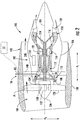
- FIG. 2 provides a schematic, cross-sectional view of the first propulsor assembly 52
- FIG. 3 provides a schematic, cross-sectional view of the second propulsor assembly 54.
- the first propulsor assembly 52 and second propulsor assembly 54 are each configured in an underwing-mounted configuration.
- one or both of the first and second propulsor assemblies 52, 54 may in other exemplary embodiments be mounted at any other suitable location.
- the exemplary hybrid-electric propulsion system 50 generally includes the first propulsor assembly 52 having a combustion engine and a prime propulsor (which, for the embodiment of FIG. 2 are configured together as a turbofan engine 100), an electric machine (which for the embodiment depicted in FIG. 2 is an electric machine 56) drivingly coupled to the combustion engine, the second propulsor assembly 54 (which for the embodiment of FIG. 3 is configured as an electric propulsor assembly 200 electrically connectable to the electric machine), an energy storage unit 55, a controller 72, and a power bus 58.
- the electric propulsor assembly 200, the energy storage unit 55, and the electric machine are each electrically connectable through one or more electric lines 60 of the power bus 58.
- the power bus 58 may include various switches or other power electronics movable to selectively electrically connect the various components of the hybrid electric propulsion system 50.
- the controller 72 is generally configured to distribute electrical power between the various components of the hybrid-electric propulsion system 50.
- the controller 72 may be operable with the power bus 58 (including the one or more switches or other power electronics) to provide electrical power to, or draw electrical power from, the various components to operate the hybrid electric propulsion system 50 between, e.g., a charging mode and a discharging mode as will be described in greater detail below.
- the electric lines 60 of the power bus 58 extending through the controller 72.
- the controller 72 may be a stand-alone controller, dedicated to the hybrid-electric propulsion system 50, or alternatively, may be incorporated into one or more of a main system controller for the aircraft 10, a separate controller for the exemplary turbofan engine 100 (such as a full authority digital engine control system for the turbofan engine 100, also referred to as a FADEC), etc.
- the energy storage unit 55 may generally be configured as an electrical energy storage unit for storing electrical energy.
- the energy storage unit 55 may be configured as one or more batteries, such as one or more lithium-ion batteries, or alternatively may be configured as any other suitable electrical energy storage devices.
- the energy storage unit 55 is configured to store a relatively large amount of electrical power.
- the energy storage unit may be configured to store at least about fifty kilowatt hours of electrical power, such as at least about sixty-five kilowatt hours of electrical power, such as at least about seventy-five kilowatt hours of electrical power, and up to about five hundred kilowatt hours of electrical power.
- the first propulsor assembly 52 includes a combustion engine mounted, or configured to be mounted, to the first wing 20 of the aircraft 10. More specifically, as is depicted, for the embodiment of FIG. 2 , the combustion engine is a turbomachine 102, and the first propulsor assembly 52 additionally includes a primary fan (referred to simply as "fan 104" with reference to FIG. 2 ). More specifically, for the embodiment depicted the turbomachine 102 and the fan 104 are configured together as part of a turbofan engine 100.
- the turbofan 100 defines an axial direction A1 (extending parallel to a longitudinal centerline 101 provided for reference) and a radial direction R1.
- the turbofan 100 includes the fan 104 and the turbomachine 102 disposed downstream from the fan 104.
- the exemplary turbomachine 102 depicted generally includes a substantially tubular outer casing 106 that defines an annular inlet 108.
- the outer casing 106 encases, in serial flow relationship, a compressor section including a booster or low pressure (LP) compressor 110 and a high pressure (HP) compressor 112; a combustion section 114; a turbine section including a first, high pressure (HP) turbine 116 and a second, low pressure (LP) turbine 118; and a jet exhaust nozzle section 120.
- LP booster or low pressure
- HP high pressure
- the exemplary turbomachine 102 of the turbofan 100 additionally includes one or more shafts rotatable with at least a portion of the turbine section and, for the embodiment depicted, at least a portion of the compressor section. More particularly, for the embodiment depicted, the turbofan 100 includes a high pressure (HP) shaft or spool 122, which drivingly connects the HP turbine 116 to the HP compressor 112. Additionally, the exemplary turbofan 100 includes a low pressure (LP) shaft or spool 124, which drivingly connects the LP turbine 118 to the LP compressor 110.
- HP high pressure
- LP low pressure
- the exemplary fan 104 depicted is configured as a variable pitch fan having a plurality of fan blades 128 coupled to a disk 130 in a spaced apart manner.
- the fan blades 128 extend outwardly from disk 130 generally along the radial direction R1.
- Each fan blade 128 is rotatable relative to the disk 130 about a respective pitch axis PI by virtue of the fan blades 128 being operatively coupled to a suitable actuation member 132 configured to collectively vary the pitch of the fan blades 128.
- the fan 104 is mechanically coupled to the LP shaft 124, such that the fan 104 is mechanically driven by the second, LP turbine 118.
- the fan 104 including the fan blades 128, disk 130, and actuation member 132, is mechanically coupled to the LP shaft 124 through a power gearbox 134, and is rotatable about the longitudinal axis 101 by the LP shaft 124 across the power gear box 134.
- the power gear box 134 includes a plurality of gears for stepping down the rotational speed of the LP shaft 124 to a more efficient rotational fan speed. Accordingly, the fan 104 is powered by an LP system (including the LP turbine 118) of the turbomachine 102.
- the disk 130 is covered by rotatable front hub 136 aerodynamically contoured to promote an airflow through the plurality of fan blades 128.
- the turbofan 100 includes an annular fan casing or outer nacelle 138 that circumferentially surrounds the fan 104 and/or at least a portion of the turbomachine 102. Accordingly, the exemplary turbofan 100 depicted may be referred to as a "ducted" turbofan engine.
- the nacelle 138 is supported relative to the turbomachine 102 by a plurality of circumferentially-spaced outlet guide vanes 140. A downstream section 142 of the nacelle 138 extends over an outer portion of the turbomachine 102 so as to define a bypass airflow passage 144 therebetween.
- the hybrid-electric propulsion system 50 additionally includes an electric machine 56, which for the embodiment depicted is configured as an electric motor/generator.
- the electric machine 56 is, for the embodiment depicted, positioned within the turbomachine 102 of the turbofan engine 100 and is in mechanical communication with one of the shafts of the turbofan engine 100. More specifically, for the embodiment depicted, the electric machine is mechanically coupled to the second, LP turbine 118 through the LP shaft 124.
- the electric machine 56 is configured to convert mechanical power of the LP shaft 124 to electric power when operated as an electric generator, and further is configured to convert electrical power to mechanical power for the LP shaft 124 when operated as an electric motor. Accordingly, the electric machine 56 may be powered by the LP system (including the LP turbine 118) of the turbomachine 102 during certain operations, and further may power (or add power to) the LP system of the turbomachine 102 in other operations.
- the electric machine 56 may be a relatively powerful electric machine.
- the electric machine 56 may be configured to generate at least about seventy-five kilowatts of electrical power, or at least about one hundred horsepower of mechanical power.
- the electric machine 56 may be configured to generate up to about one hundred and fifty kilowatts of electrical power and up to at least about two hundred horsepower of mechanical power, such as up to about one megawatt of electrical power and up to at least about one thousand three hundred horsepower of mechanical power.
- the electric machine 56 may instead be positioned at any other suitable location within the turbomachine 102 or elsewhere, and may be, e.g., powered in any other suitable manner.
- the electric machine 56 may be, in other embodiments, mounted coaxially with the LP shaft 124 within the turbine section, or alternatively may be offset from the LP shaft 124 and driven through a suitable gear train.
- the electric machine 56 may instead be powered by the HP system, i.e., by the HP turbine 116 through the HP shaft 122, or by both the LP system (e.g., the LP shaft 124) and the HP system (e.g., the HP shaft 122) via a dual drive system.
- the electric machine 56 may include a plurality of electric machines, e.g., with one being drivingly connected to the LP system (e.g., the LP shaft 124) and one being drivingly connected to the HP system (e.g., the HP shaft 122).
- the electric machine 56 may instead be configured simply as an electric generator.
- the exemplary turbofan engine 100 depicted in FIG. 2 may, in other exemplary embodiments, have any other suitable configuration.
- the fan 104 may not be a variable pitch fan, and further, in other exemplary embodiments, the LP shaft 124 may be directly mechanically coupled to the fan 104 (i.e., the turbofan engine 100 may not include the gearbox 134).
- the first propulsor assembly 52 may include any other suitable type of engine.
- the turbofan engine 100 may instead be configured as a turboprop engine or an unducted turbofan engine.
- the turbofan engine 100 may instead be configured as any other suitable combustion engine for driving the electric machine 56.
- the turbofan engine may be configured as a turboshaft engine, or any other suitable combustion engine.
- the turbofan engine 100 further includes a controller 150, and although not depicted, one or more sensors.
- the controller 150 may be a full authority digital engine control system, also referred to as a FADEC.
- the controller 150 of the turbofan engine 100 may be configured to control operation of, e.g., the actuation member 132, a fuel delivery system to the combustion section 114 (not shown), etc.
- the controller 150 may be operably connected to the one or more sensors to receive data from the sensors and determine various operational parameters of the turbofan engine 100. For example, the controller 150 may determine one or more of an exhaust gas temperature, a rotational core speed, a compressor discharge temperature, etc. Further, referring back also to FIG.
- the controller 150 of the turbofan engine 100 is operably connected to the controller 72 of the hybrid-electric propulsion system 50.
- the controller 72 may further be operably connected to one or more of the first propulsor assembly 52 (including controller 150), the electric machine 56, the second propulsor assembly 54, and the energy storage unit 55 through a suitable wired or wireless communication system (depicted in phantom).
- the exemplary hybrid-electric propulsion system 50 additionally includes the second propulsor assembly 54 mounted, for the embodiment depicted, to the second wing 22 of the aircraft 10.
- the second propulsor assembly 54 is generally configured as an electric propulsor assembly 200 including an electric motor 206 and a propulsor/fan 204.
- the electric propulsor assembly 200 defines an axial direction A2 extending along a longitudinal centerline axis 202 that extends therethrough for reference, as well as a radial direction R2.
- the fan 204 is rotatable about the centerline axis 202 by the electric motor 206.
- the fan 204 includes a plurality of fan blades 208 and a fan shaft 210.
- the plurality of fan blades 208 are attached to/rotatable with the fan shaft 210 and spaced generally along a circumferential direction of the electric propulsor assembly 200 (not shown).
- the plurality of fan blades 208 may be attached in a fixed manner to the fan shaft 210, or alternatively, the plurality of fan blades 208 may be rotatable relative to the fan shaft 210, such as in the embodiment depicted.
- the plurality of fan blades 208 each define a respective pitch axis P2, and for the embodiment depicted are attached to the fan shaft 210 such that a pitch of each of the plurality of fan blades 208 may be changed, e.g., in unison, by a pitch change mechanism 211. Changing the pitch of the plurality of fan blades 208 may increase an efficiency of the second propulsor assembly 54 and/or may allow the second propulsor assembly 54 to achieve a desired thrust profile.
- the fan 204 may be referred to as a variable pitch fan.
- the electric propulsor assembly 200 depicted additionally includes a fan casing or outer nacelle 212, attached to a core 214 of the electric propulsor assembly 200 through one or more struts or outlet guide vanes 216.
- the outer nacelle 212 substantially completely surrounds the fan 204, and particularly the plurality of fan blades 208. Accordingly, for the embodiment depicted, the electric propulsor assembly 200 may be referred to as a ducted electric fan.
- the fan shaft 210 is mechanically coupled to the electric motor 206 within the core 214, such that the electric motor 206 drives the fan 204 through the fan shaft 210.
- the fan shaft 210 is supported by one or more bearings 218, such as one or more roller bearings, ball bearings, or any other suitable bearings.
- the electric motor 206 may be an inrunner electric motor (i.e., including a rotor positioned radially inward of a stator), or alternatively may be an outrunner electric motor (i.e., including a stator positioned radially inward of a rotor), or alternatively, still, may be an axial flux electric motor (i.e., with the rotor neither outside the stator nor inside the stator, but rather offset from it along the axis of the electric motor).
- the electric power source e.g., the electric machine 56 or the energy storage unit 55
- the electric propulsor assembly 200 i.e., the electric motor 206
- the electric motor 206 is in electrical communication with the electric machine 56 through the electrical power bus 58, and more particularly through the one or more electrical cables or lines 60 extending therebetween.
- the exemplary hybrid-electric propulsion system 50 may have any other suitable configuration, and further, may be integrated into an aircraft 10 in any other suitable manner.
- the electric propulsor assembly 200 of the hybrid electric propulsion system 50 may instead be configured as a plurality of electric propulsor assemblies 200 and/or the hybrid electric propulsion system 50 may further include a plurality of combustion engines (such as turbomachines 102) and electric machines 56.
- the electric propulsor assembly(ies) 200 and/or combustion engine(s) and electric machine(s) 56 may be mounted to the aircraft 10 at any other suitable location in any other suitable manner (including, e.g., tail mounted configurations).
- FIGS. 4 and 5 an aircraft 10 and hybrid-electric propulsion system 50 in accordance with still another exemplary embodiment of the present disclosure is depicted.
- the exemplary aircraft 10 and hybrid-electric propulsion system 50 of FIGS. 4 and 5 may be configured in substantially the same manner as exemplary aircraft 10 and hybrid-electric propulsion system 50 of FIGS. 1 through 3 , and accordingly, the same or similar numbers may refer to same or similar parts.
- the exemplary aircraft 10 of FIGS. 4 and 5 generally includes a fuselage 12, an empennage 19, an energy storage unit 55, a first wing 20, and a second wing 22.
- the hybrid-electric propulsion system 50 includes a first propulsor assembly 52 and one or more electric machines (i.e., generators 56A, 56B, discussed below) mechanically driven by the first propulsor assembly 52.
- the hybrid-electric propulsion system 50 includes a second propulsor assembly 54, which is an electric propulsor assembly 200.
- the first propulsor assembly 52 includes a first aircraft engine and a second aircraft engine, configured as first turbofan engine 100A and a second turbofan engine 100B, respectively.
- turbofan engines 100A, 100B may be configured as turbofan engines (see, e.g., FIG. 2 ), or any other suitable type of combustion engine, attached to and suspended beneath the wings 20, 22 in an under-wing configuration.
- the hybrid-electric propulsion system 50 further includes one or more electric machines operable with each of the turbofan engines 100A, 100B.
- the hybrid-electric propulsion system 50 further includes a first electric machine 56A operable with the first turbofan engine 100A and a second electric machine 56B operable with the second turbofan engine 100B.
- a first electric machine 56A operable with the first turbofan engine 100A and a second electric machine 56B operable with the second turbofan engine 100B.
- the electric machines 56A, 56B may be positioned within a respective turbofan engines 100A, 100B (see, e.g., FIG. 2 ).
- the electric propulsion assembly includes an electric propulsor assembly 200 configured to be mounted at the aft end 18 of the aircraft 10 to at least one of the empennage 19 of the aircraft 10 or the fuselage 12 of the aircraft, and hence the electric propulsor assembly 200 depicted may be referred to as an "aft engine.” More specifically, the exemplary electric propulsor assembly 200 depicted is mounted to the fuselage 12 of the aircraft 10 at the aft end 18 of the aircraft 10 and configured to ingest and consume air forming a boundary layer over the fuselage 12 of the aircraft 10. Accordingly, the exemplary electric propulsor assembly 200 depicted in FIGS.
- the electric propulsor assembly 200 is mounted to the aircraft 10 at a location aft of the wings 20, 22 and/or the turbofan engines 100A, 100B. Specifically, for the embodiment depicted, the electric propulsor assembly 200 is fixedly connected to the fuselage 12 at the aft end 18, such that the electric propulsor assembly 200 is incorporated into or blended with a tail section at the aft end 18.
- the hybrid electric propulsion assembly further includes a controller 72.
- the energy storage unit 55 may be configured, in certain operating conditions, to receive electrical power from one or both of the first electric machine 56A and the second electric machine 56B. Further, in certain operating conditions, the energy storage unit 55 may be configured to provide stored electrical power to the electric propulsor assembly 200.
- the controller 72 is operably connected to turbofan engines 100A, 100B, electric machines 56A, 56B, electric propulsor assembly 200, energy storage unit 55, and power bus 58, such that the controller 72 may, e.g., direct electrical power between the various components of the hybrid electric propulsion system 50.
- any other suitable aircraft 10 may be provided having a hybrid-electric propulsion system 50 configured in any other suitable manner.
- the electric propulsor assembly 200 may be incorporated into the fuselage of the aircraft 10, and thus configured as a "podded engine,” or pod-installation engine. Further, in still other embodiments, the electric propulsor assembly 200 may be incorporated into a wing of the aircraft 10, and thus may be configured as a "blended wing engine.”
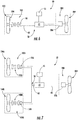
- FIG. 6 provides a schematic diagram of the example hybrid electric propulsion system 50 described above with reference to FIGS. 1 through 3 .
- the example hybrid-electric propulsion system 50 of FIG. 6 generally includes a combustion engine, a prime propulsor 104, an electric machine 56, an energy storage unit 55, a controller 72, a power bus 58, and an electric propulsor assembly 200, the electric propulsor assembly 200 generally including an electric motor 206 drivingly connected to a propulsor or fan 204.
- the combustion engine is configured as a turbomachine 102 and is mechanically coupled to the prime propulsor 104 for driving the prime propulsor 104 and generating thrust (the turbomachine 102 and prime propulsor 104 together configured as a turbofan engine 100). Additionally, the turbomachine 102 is mechanically coupled to the electric machine 56 to generate electrical power.
- the power bus 58 generally electrically connects the electric machine 56, the energy storage unit 55, and the electric motor 206 of the electric propulsor assembly 200. More specifically, for the example depicted, the power bus 58 electrically connects the electric machine 56, the energy storage unit 55, and the electric motor 206 all through the controller 72.
- the controller 72 may instead be operably connected to, e.g., one or more switches or other hardware for directing electrical power between the electric machine 56, the energy storage unit 55, and the electric motor 206.
- the hybrid electric propulsion system 50 may further include one or more rectifiers, inverters, converters, or other power electronics for conditioning or converting the electrical power within and throughout the hybrid electric propulsion system 50.
- the example hybrid-electric propulsion system 50 is operable in a variety of different modes.
- the example hybrid-electric propulsion system 50 may generally be operable in an electric charge mode, in which at least a portion of the electric power generated by the electric machine 56 is transferred through the power bus 58 to the energy storage unit 55 to charge the energy storage unit 55.
- the electric charge mode at least a portion of the electric power generated by the electric machine 56 may further be transferred through the power bus 58 to the electric motor 206 of the electric propulsor assembly 200.
- a ratio of an amount of the electric power transferred to the energy storage unit 55 to an amount of the electric power transferred to the electric motor 206 may be a fixed ratio, or alternatively, may vary based on one or more operating parameters of the hybrid electric propulsor assembly 200.
- the ratio may be between about 1:10 and about 10:1, such as between about 1:5 and about 5:1.
- the example hybrid-electric propulsion system 50 may further be operable in an electric discharge mode, in which electrical power stored within the energy storage unit 55 is transferred through the power bus 58 to the electric motor 206 of the electric propulsor assembly 200.
- the electric motor 206 of the electric propulsor assembly 200 may receive electrical power solely from the energy storage unit 55, or may receive a combination of electrical power from the energy storage unit 55 as well as from the electric machine 56.
- the energy storage unit 55 may receive no electrical power from the electric machine 56 during the electric discharge mode. Additionally, or alternatively, in other examples, the energy storage unit 55 may further provide electrical power to the electric machine 56 to drive one or more components of the turbomachine 102 in the electric discharge mode.
- example hybrid-electric propulsion system 50 may additionally be operable in a maintain mode.
- electrical power is neither transferred to or from the energy storage unit 55, and instead any charge within the energy storage unit 55 is maintained.
- substantially all of the electric power generated by the electric machine 56 (if any) may be transferred directly to the electric motor 206 of the electric propulsor assembly 200.
- the hybrid-electric propulsion system 50 may be configured in any other suitable manner.
- FIG. 7 the exemplary hybrid electric propulsion system 50 of FIGS. 4 and 5 is depicted schematically. As is discussed above, the hybrid electric propulsion system 50 of FIGS. 4 and 5 , depicted schematically in FIG. 7 , is configured in a similar manner as the hybrid electric propulsion system 50 of FIGS. 1 through 3 , depicted schematically in FIG. 6 .
- the exemplary hybrid-electric propulsion system 50 generally includes a combustion engine (i.e., turbomachine 102 for the embodiment depicted), a prime propulsor 104, an electric machine 56, an energy storage unit 55, a controller 72, a power bus 58, and an electric propulsor assembly 200, with the electric propulsor assembly 200 generally including an electric motor 206 drivingly connected to a propulsor 204.
- the turbomachine 102 is instead configured as a plurality of turbomachines 102, and the electric machine 56 is instead configured as a plurality of electric machines 56. More specifically, for the embodiment of FIG. 7 , the turbomachine 102 is configured as a first turbomachine 102A and a second turbomachine 102B, and the electric machine 56 is configured as a first electric machine 56A and a second electric machine 56B.
- the first turbomachine 102A is coupled to and mechanically drives the first electric machine 56A such that the first electric machine 56A may generate electrical power
- the second turbomachine 102B is coupled to and mechanically drives the second electric machine 56B such that the second electric machine 56B may generate electrical power.
- Each of the first and second electric machines 56A, 56B are electrically coupled to the power bus 58.
- the power bus 58 accordingly electrically connects the first electric machine 56A, the second electric machine 56B, the energy storage unit 55, and the electric motor 206 of the electric propulsor assembly 200 all through the controller 72.
- the exemplary hybrid-electric propulsion system 50 of the exemplary embodiment of FIG. 7 is operable between an electric charge mode, a maintain mode, and an electric discharge mode. In the electric charge mode at least a portion of the electric power generated by one or both of the first electric machine 56A and second electric machine 56B is transferred through the power bus 58 to the energy storage unit 55 to charge the energy storage unit 55.
- substantially all of the electrical power generated by one or both of the first electric machine 56A and second electric machine 56B may be transferred to the energy storage unit 55 for charging the energy storage unit 55.
- substantially all of the electric power generated by the first electric machine 56A may be transferred to the energy storage unit 55 for charging the energy storage unit 55
- substantially all the electrical power from the second electric machine 56B may be transferred to the electric motor 206 for driving the electric motor 206.
- a portion of the electrical power generated by one or both of the first electric machine 56A and second electric machine 56B may be transferred to the energy storage unit 55 for charging energy storage unit 55.
- the electric motor 206 of the electric propulsor assembly 200 may receive electrical power solely from the energy storage unit 55, or may receive a combination of electrical power from the energy storage unit 55 as well as from one or both of the first electric machine 56A and second electric machine 56B.
- first electric machine 56A and second electric machine 56B may receive electrical power from the energy storage unit 55 during operation of the hybrid electric propulsion system in the electric discharge mode.
- one of the first turbomachine 102A or second turbomachine 102B may be operated in a "low-power" mode, while the other is operated in a "high-power” mode during operation of the hybrid electric propulsion system in the electric discharge mode.
- the electric machine 56 coupled to the turbomachine 102 operated in the low-power mode may receive electrical power to drive one or more components of such turbomachine 102 (e.g., drive, or assist with driving, a prime propulsor), while the electric machine 56 coupled to the turbomachine 102 operated in the high power mode may generate electrical power, and provide at least a portion of such electrical power to one or more of the energy storage unit 55, the electric propulsor assembly 200, and/or the other electric motor 56 coupled to the turbomachine 102 operated the low-power mode.
- electrical power to drive one or more components of such turbomachine 102 (e.g., drive, or assist with driving, a prime propulsor)
- the electric machine 56 coupled to the turbomachine 102 operated in the high power mode may generate electrical power, and provide at least a portion of such electrical power to one or more of the energy storage unit 55, the electric propulsor assembly 200, and/or the other electric motor 56 coupled to the turbomachine 102 operated the low-power mode.
- FIG. 8 a schematic diagram of a hybrid electric propulsion system 50 in accordance with yet another example useful for understanding the invention is provided.
- the exemplary hybrid electric propulsion system 50 of FIG. 8 is configured in substantially the same manner as example hybrid electric propulsion system 50 of FIG. 6 .
- the electric propulsor assembly 200 is instead configured as a plurality of electric propulsor assemblies 200, with each of the plurality of electric propulsor assemblies 200 including an electric motor 206 drivingly connected to a respective propulsor 204. More specifically, for the example of FIG. 8 , the electric propulsor assembly 200 is configured as a first electric propulsor assembly 200A and a second electric propulsor assembly 200B.
- the first electric propulsor assembly 200A includes a first electric motor 206A drivingly connected to a first propulsor 204A, and similarly, the second electric propulsor assembly 200B includes a second electric motor 206B drivingly connected to a second propulsor 204B.
- the power bus 58 electrically connects the electric machine 56, the energy storage unit 55, the first electric motor 206A of the first electric propulsor assembly 200A, and the second electric motor 206B of the second electric propulsor assembly 200B. More specifically, for the example depicted, the power bus 58 electrically connects the electric machine 56, the energy storage unit 55, and the first and second electric motors 206A, 206B all through the controller 72. Further, the example hybrid-electric propulsion system 50 of the example of FIG. 8 is also operable between an electric charge mode, a maintain mode, and an electric discharge mode.
- At least a portion of the electric power generated by the electric machine 56 is transferred through the power bus 58 to the energy storage unit 55 to charge the energy storage unit 55.
- at least a portion of the electric power may optionally also be transferred to one or both of the first electric motor 206 and second electric motor 206.
- electrical power is neither transferred to or from the energy storage unit 55, and instead any charge within the energy storage unit 55 is maintained.
- first electric motor 206A and the second electric motor 206B when in the electric discharge mode electrical power stored within the energy storage unit 55 may be transferred through the power bus 58 to one or both of the first electric motor 206A and the second electric motor 206B.
- one of the first electric motor 206A or second electric motor 206B may receive electrical power from the energy storage unit 55, and the other of the first electric motor 206A or second electric motor 206B may receive electrical power directly from the electric machine 56.
- both the first electric motor 206A and the second electric motor 206B may receive electrical power solely from the energy storage unit 55, or may each receive electrical power from both the energy storage unit 55 and the electric machine 56.
- the electric machine 56 may receive electrical power from the energy storage unit 55 during operation of the hybrid electric propulsion system in the electric discharge mode to drive one or more components of the turbomachine 102.
- any other suitable hybrid-electric propulsion system 50 may be provided.
- FIGS. 9 and 10 an aircraft and a hybrid electric propulsion system in accordance with another example useful in understanding the invention are provided. More particularly, referring first to FIG. 9 , a perspective view is provided of an example aircraft 300 in accordance with still another example useful in understanding the invention.
- the aircraft 300 generally defines a transverse direction T, a longitudinal direction L, and a vertical direction V. In operation, the aircraft 300 may move along or around the transverse direction T, the longitudinal direction L, and/or the vertical direction V.
- the aircraft 300 includes an airframe 312 defining a cockpit.
- the aircraft 300 further includes a main rotor assembly 340 and a tail rotor assembly 350.
- the main rotor assembly 340 includes a main rotor hub 342 and a plurality of main rotor blades 344. As shown, each main rotor blade 344 extends outwardly from the main rotor hub 342.
- the tail rotor assembly 350 includes a tail rotor hub 352 and a plurality of tail rotor blades 354. Each tail rotor blade 354 extends outwardly from the tail rotor hub 352.
- the aircraft 300 includes a hybrid electric propulsion assembly (not labeled), as will be described in greater detail below.
- the hybrid electric propulsion assembly generally includes a first gas turbine engine 360 and a second gas turbine engine 362. It should be appreciated, that in at least certain examples, one or both of the first and second gas turbine engines 360, 362 of the aircraft 300 in FIG. 9 may be configured in substantially the same manner as the gas turbine engine 402 depicted in FIG. 10 , described below, and further that the hybrid electric propulsion system may further include one or more of the additional components from the example hybrid electric propulsion system depicted in FIG. 10 .
- first and second gas turbine engines 360, 362 may be mechanically coupled to one another such that the first and second gas turbine engines 360, 362 operate together.
- first and second gas turbine engines 360, 362 may be ganged together in a gearbox by, e.g., differentials and one-way clutches (such as sprag clutches), such that they operate together.
- first and second gas turbine engines 360, 362 may generally generate and transmit power to drive rotation of the main rotor blades 344 and the tail rotor blades 354.
- rotation of the main rotor blades 344 generates lift for the aircraft 300 (or vertical thrust) will, while rotation of the tail rotor blades 354 generates sideward thrust at the tail rotor assembly 350 and counteracts torque exerted on the airframe 312 by the main rotor blades 344.
- Rotation of the tail rotor blades 354 may also pivot the aircraft 300 about the vertical direction V.
- FIG. 10 a schematic view is provided of a hybrid electric propulsion system 400 for an aircraft in accordance with an example useful for understanding the invention.
- the example hybrid electric propulsion system 400 may be incorporated into an aircraft similar to the example aircraft 300 described above with reference to FIG. 9 .
- the hybrid electric propulsion system 400 may instead be utilized with any other suitable aircraft, as described below.
- the hybrid electric propulsion system 400 generally includes a gas turbine engine 402, a prime propulsor mechanically coupled to the gas turbine engine 402, an electric machine 462 also mechanically coupled to the gas turbine engine 402, an energy storage unit 464, and a controller 466. Functionality of each of these components is as follows.
- the gas turbine engine 402 defines a longitudinal or centerline axis 403 extending therethrough for reference.
- the gas turbine engine 402 generally includes a substantially tubular outer casing 404 that defines an annular inlet 406.
- the outer casing 404 encloses, in serial flow relationship, a gas generator compressor 410 (or high pressure compressor), a combustion section 430, a turbine section 440, and an exhaust section 450.
- the exemplary gas generator compressor 410 depicted includes an annular array of inlet guide vanes 412, one or more sequential stages of compressor blades 414, and a stage of centrifugal rotor blades 418.
- the gas generator compressor 410 may also include a plurality of fixed or variable stator vanes.
- the combustion section 430 generally includes a combustion chamber 432, one or more fuel nozzles 434 extending into the combustion chamber 432, and a fuel delivery system 438.
- the fuel delivery system 438 is configured to provide fuel to the one or more fuel nozzles 434, which, in turn, supply fuel to mix with compressed air from the gas generator compressor 410 entering the combustion chamber 432. Further, the mixture of fuel and compressed air is ignited within the combustion chamber 432 to form combustion gases. As will be described below in more detail, the combustion gases drive both the gas generator compressor 410 and the turbines within the turbine section 440.
- the turbine section 440 includes a gas generator turbine 442 (or high pressure turbine) and a power turbine 444 (or low pressure turbine).
- the gas generator turbine 442 includes one or more sequential stages of turbine rotor blades 446, and may further include one or more sequential stages of stator vanes (not shown).
- the power turbine 444 includes one or more sequential stages of turbine rotor blades 448, and may further include one or more sequential stages of stator vanes (also not shown).
- the gas generator turbine 442 is drivingly connected to the gas generator compressor 410 via a gas generator shaft 452
- the power turbine 444 is drivingly connected to an output shaft 456 via a power turbine shaft 454.
- the combustion gases drive both the gas generator turbine 442 and the power turbine 444.
- the gas generator turbine 442 rotates around the centerline axis 403
- the gas generator compressor 410 and the gas generator shaft 452 both also rotate around the centerline axis 403.
- the power turbine shaft 454 rotates and transfers rotational energy to the output shaft 456. Accordingly, it will be appreciated that the gas generator turbine 442 drives the gas generator compressor 410 and the power turbine 444 drives the output shaft 456.
- the gas turbine engine 402 of FIG. 10 may instead have any other suitable configuration.
- the combustion section 430 may include a reverse flow combustor
- the gas turbine engine may include any suitable number of compressors, spools, and turbines, etc.
- the output shaft 456 is configured to rotate the prime propulsor of the hybrid electric propulsion system 400, which for the example depicted is a main rotor assembly 458 (which may be configured in substantially the same manner as the exemplary main rotor assembly 340 of the aircraft 300 of FIG. 9 ).
- the output shaft 456 is mechanically coupled to the main rotor assembly 458 through a gearbox 460.
- the output shaft 456 may be coupled to the main rotor assembly 458 in any other suitable manner.
- the example hybrid electric propulsion system 400 additionally includes the electric machine 462, which may be configured as an electric motor/generator, and the energy storage unit 464.
- the electric machine 462 is directly mechanically coupled to the output shaft 456 of the gas turbine engine 402 (i.e., a rotor of the electric machine 462 is mounted to the output shaft 456).
- the electric machine 462 may instead be mechanically coupled to the output shaft 456 in any other suitable manner, such as through a suitable gear train.
- the electric machine 462 may be configured to convert electrical power received to mechanical power (i.e., function as an electric motor), and further may be configured to receive mechanical power and convert such mechanical power to electrical power (i.e., function as an electric machine). Therefore, it will be appreciated that the electric machine 462 may be configured to increase or decrease an effective mechanical power output of the gas turbine engine 402, and more particularly of the output shaft 456 of the gas turbine engine 402 by adding power to, or extracting power from, the output shaft 456.
- the energy storage unit 464 may be any component suitable for receiving, storing, and providing electrical power.
- the energy storage unit 464 may be a battery pack, such as a plurality of lithium-ion batteries. In other examples, however, any other suitable chemistry of batteries may be utilized.
- the energy storage unit 464 may be configured in substantially the same manner as the energy storage unit 55 described above (e.g., may store at least about fifty kilowatt-hours of electrical power), and the electric machine 462 may be configured as a relatively powerful electric machine also in substantially the same manner as the electric machine 56 described above.
- the electric machine 462 may be configured to generate at least about seventy-five kilowatts of electrical power, or at least about one hundred horsepower of mechanical power.
- the electric machine 462 may be configured to generate up to about one hundred and fifty kilowatts of electrical power and up to at least about two hundred horsepower of mechanical power, such as up to about one megawatt of electrical power and up to at least about one thousand three hundred horsepower of mechanical power.
- the controller 466 is operably connected to, e.g., the electric machine 462 and the energy storage unit 464 and configured to electrically connect these components and direct electrical power between these components.
- the hybrid electric propulsion system 400 is configured to add power to, or extract power from, the gas turbine engine 402 using the electric machine 462 by way of an electrical connection between the electric machine 462 and the energy storage unit 464. More particularly, for the example depicted, the hybrid electric propulsion system is operable between an electric charge mode, an electric discharge mode, and optionally a maintain mode.
- power When operated in the electric charge mode, power may be extracted from the gas turbine engine 402 by operating the electric machine 462 as an electric machine, such that the electric machine 462 generates electrical power, and provides such electrical power to the energy storage unit 464.
- power when operated in the electric discharge mode, power may be provided to the gas turbine engine 402 by operating the electric machine 462 as an electric motor, such that the electric power provided from the energy storage unit 464 to the electric machine 462 provides additional mechanical power to the output shaft 456 of the turboshaft engine 402.
- the hybrid electric propulsion system 400 may further include various power electronics components operable with the controller 466 (and/or a power bus, not labeled) to facilitate the controller 466 directing the electrical power to and/or from energy storage unit 464.
- These various power electronics components may further convert and/or condition electrical power provided between these components as necessary or desired.
- the aircraft may be any other suitable rotary wing aircraft, typically referred to as a helicopter. Additionally, or alternatively, the aircraft may instead be configured as a vertical takeoff and landing aircraft, a fixed wing aircraft commonly referred to as an airplane (similar to the embodiment of FIGS. 1 through 5 and 7 ), etc.
- FIG. 11 a flow diagram of a method 500 for operating a hybrid-electric propulsion system for an aircraft is provided.
- the hybrid-electric propulsion system operated by the method 500 may be configured in substantially the same manner as one or more of the exemplary hybrid-electric propulsion systems described above with reference to FIGS. 1 through 10 .
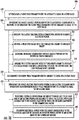
- the exemplary method 500 generally includes at (502) determining a flight phase parameter for the aircraft is equal to a first value, and at (504) operating the hybrid electric propulsion system in an electric charge mode in response to determining the flight phase parameter for the aircraft is equal to the first value at (502). More particularly, for the exemplary aspect depicted, operating the hybrid electric propulsion system in an electric charge mode at (504) includes at (505) driving the electric machine with a combustion engine to generate electrical power; at (506) driving a prime propulsor with the combustion engine to generate thrust; and at (507) charging an energy storage unit with at least a portion of the electrical power generated. Further, as is described in greater detail below, in certain exemplary aspects, the flight phase parameter value may correspond to one or more of a takeoff flight phase, a top of climb flight phase, a cruise flight phase, or a descent flight phase.
- the exemplary method 500 further includes at (508) determining the flight phase parameter for the aircraft is equal to a second value.
- the second value is different than the first value.
- the method 500 includes at (510) operating the hybrid-electric propulsion system in an electric discharge mode in response to determining flight phase parameter for the aircraft is equal to the second value at (508).
- operating the hybrid-electric propulsion system in the electric discharge mode at (510) includes at (512) providing electrical power from the energy storage unit to at least one of an electric propulsor assembly to drive the electric propulsor assembly or to the electric machine to drive one or more components of the combustion engine. More specifically for the exemplary aspect of the method 500 depicted in FIG.
- the hybrid electric propulsion system includes an electric propulsor assembly, and providing electrical power from the energy storage unit at (512) includes at (513) providing electrical power from the energy storage unit to electric propulsor assembly to drive the electric propulsor assembly and generate thrust for the aircraft, and more particularly, providing electrical power from the energy storage unit to an electric motor of the electric propulsor assembly, such that the electric motor may drive a propulsor of the electric propulsor assembly (e.g., a fan).
- a propulsor of the electric propulsor assembly e.g., a fan
- the method 500 further includes at (514) determining the flight phase parameter for the aircraft is equal to a third value; at (515) operating the hybrid-electric propulsion system in the electric charge mode in response to determining the flight phase parameter for the aircraft is equal to the third value at (514); at (516) determining the flight phase parameter for the aircraft is equal to a fourth value; and at (518) operating the hybrid electric propulsion system in the electric discharge mode in response to determining the flight phase parameter is equal to the fourth value at (516).
- operating the hybrid electric propulsion system in the electric charge mode at (515) may be similar to operating the hybrid electric propulsion system in the electric charge mode at (504), and similarly operating the hybrid electric propulsion system in the electric discharge mode at (518) may be similar to operating the hybrid electric propulsion system in the electric discharge mode at (510).
- determining the flight phase parameter for the aircraft is equal to the first value at (502)
- determining the flight phase parameter the aircraft is equal to the second value at (508)
- determining the flight phase parameter the aircraft is equal to the fourth value at (518) may each occur sequentially.
- determining the flight phase parameter is equal to the first value at (502) may include any suitable means for determining the flight phase parameter.
- determining the flight phase parameter is equal to the first value at (502) may include at (520) determining the value of the flight phase parameter based on a performance map for the aircraft.
- the performance map for the aircraft may be a chart showing various flight phases for a particular flight over a span of time.
- determining the flight phase parameter is equal to the second value at (508), determining the flight phase parameter of the aircraft is equal to the third value at (514), and determining the flight phase parameter the aircraft is equal to the fourth value at (518) may each also include determining the value of the flight phase parameter based on a performance map for the aircraft.
- a performance map 600 for the exemplary aircraft for a particular flight is depicted.
- the performance map 600 for the embodiment of FIG. 13 shows altitude (Y-axis) over time (X-axis).
- the performance map identifies four distinct flight phases, namely: a takeoff flight phase 602, a top of climb flight phase 604, a cruise flight phase 606, and a descent phase 608. Accordingly, referring back also to the exemplary method 500 of FIG.
- the first value of the flight phase parameter may correspond to the aircraft being in the takeoff flight phase 602
- the second value of the flight phase parameter may correspond to the aircraft being in the top of flight phase 604
- the third value of the flight phase parameter may correspond to the aircraft being in a cruise flight phase 606
- the fourth value of the flight phase parameter may correspond to the aircraft being in the descent flight phase 608.
- the hybrid-electric propulsion system may charge the energy storage unit during at least a portion of the takeoff flight phase 602, may discharge electrical power from the energy storage unit during a top of flight phase 604, may recharge energy storage unit during at least a portion of the cruise flight phase 606, and further made discharge electrical power from the energy storage unit during the descent flight phase 608.
- determining the value of the flight phase parameter based on a performance map for the aircraft at (520) may further include at (521) determining the value of the flight phase parameter based on the performance map for the aircraft and one or more operational parameters of the aircraft, such as altitude, flight duration, etc.
- determining the flight phase parameter for the aircraft is equal to the first value at (502) may include any other suitable steps or methods.
- determining the flight phase parameter for the aircraft is equal to the first value at (502) may include at (522) determining one or more operational parameters of the aircraft, and at (524) determining a value of the flight phase parameter based at least in part on the determined operational parameter of the aircraft.
- the one or more operational parameters of the aircraft may include one or more of an altitude of the aircraft, a change in altitude of the aircraft, an airspeed of the aircraft, a change in airspeed of the aircraft, a duration of the current flight of the aircraft, or any other suitable operational parameter which may be indicative of a flight phase of the aircraft.
- determining the flight phase parameter is equal to the first value, second value, third value and fourth value at (502), (508), (514), and (516) may each also include determining a value of the flight phase parameter based at least in part on a determined operational parameter of the aircraft, and further may not occur sequentially and instead may occur in any other suitable order.
- the flight phase parameter being equal to the first value may correspond to the aircraft being in a cruise flight phase 606, and the flight phase parameter being equal to the second value may correspond to the aircraft being in a descent flight phase 608.
- the flight phase parameter may be determined to have any other suitable value.
- the flight phase parameter being equal to the first value may correspond to the aircraft being in a first cruise flight phase
- the flight phase parameter being equal to the second value may correspond to the aircraft being a second cruise flight phase.
- the second cruise flight phase may be sequential with the first cruise flight phase.
- the first and second values of the flight phase parameter correspond to sequential phases of the cruise portion of the (i.e., a first cruise flight phase 606A and a second cruise flight phase 606B).
- the aircraft further defines two descent flight phases 608A, 608B.
- the aircraft may define any suitable number of flight phases. Additionally, it should be appreciated, that although not described with reference to FIG. 11 through 14 , in other exemplary aspects, the method 500 may further include operating the hybrid electric propulsion in a maintain mode in response to one or more of the values of the flight phase parameter.
- FIG. 15 provides a flow diagram of another exemplary aspect of the exemplary method 500 described above with reference to FIG. 11 .
- the exemplary method 500 of FIG. 15 may accordingly be similar to the exemplary method 500 of FIG. 11 .
- the method 500 of FIG. 15 generally includes at (502) determining a flight phase parameter for the aircraft is equal to a first value, and at (504) operating the hybrid electric propulsion system in an electric charge mode in response to determining the flight phase parameter for the aircraft is equal to the first value at (502).
- the exemplary aspect of the method 500 depicted in FIG. 15 further includes at (508) determining the flight phase parameter for the aircraft is equal to a second value, and at (510) operating the hybrid-electric propulsion system in an electric discharge mode in response to determining flight phase parameter for the aircraft is equal to the second value at (508).
- the exemplary method further includes modifying operation of the combustion engine in response to determining a value of the flight phase parameter the aircraft. More specifically, for the exemplary aspect depicted, the exemplary method 500 includes at (526) modifying operation of the combustion engine response to determining the flight phase parameter for the aircraft is equal to the second value at (508).
- modifying operation of the combustion engine at (526) includes at (528) operating the combustion engine in a low power mode.
- Operating the combustion engine in the low power mode at (528) may include operating the combustion engine in an idle or sub-idle mode (e.g., at a rotational speed less than or equal to about fifty percent of a maximum rotational speed, such as less than or equal to about forty percent of a maximum rotational speed).
- an idle or sub-idle mode e.g., at a rotational speed less than or equal to about fifty percent of a maximum rotational speed, such as less than or equal to about forty percent of a maximum rotational speed.
- such may be done to generate a minimum amount of thrust with the prime propulsor, or simply to operate the combustion engine more efficiently.
- the minimum amount of thrust may be a thrust less than or equal to about twenty-five percent of a maximum amount thrust.
- the method 500 includes at (510) operating the hybrid electric propulsion system in the electric discharge mode in response to determining the flight phase parameter for the aircraft is equal to the second value.
- operating the hybrid electric propulsion system in the electric discharge mode at (510) further includes at (529) providing electrical power from the energy storage unit to the electric machine to drive one or more components of the combustion engine.
- the electric machine may supplement an output power of the combustion engine and provide power to drive the prime propulsor when the combustion engine is operated in the low power mode at (528).
- the combustion engine is a first combustion engine
- the prime propulsor is a first prime propulsor
- the electric machine is a first electric machine.
- the hybrid electric propulsion system further includes a second combustion engine, a second prime propulsor, and a second electric machine.
- the second combustion engine is mechanically coupled to the second prime propulsor, and is further mechanically coupled to the second electric machine.
- modifying operation of the first combustion engine at (526) further includes at (534) modifying operation of the second combustion engine of the hybrid-electric propulsion system such that the second combustion engine operates differently than the first combustion engine (e.g., at a different rotational core speed), and more specifically, at (536) operating the second combustion engine in a high power mode to mechanically drive the second prime propulsor and further to drive the second electric machine to generate electrical power.
- operating the second combustion engine in the high power mode at (536) may include operating the second combustion engine at a rotational speed at least fifty percent greater than a rotational speed of the first combustion engine when operated in the low power mode at (528) (the rotational speed referring to a core speed, N2).
- an effective power output of the second combustion engine may be substantially equal to an effective power output of the first combustion engine, with the differential being made up with the respective electric machines.
- the effective power output may refer to an effective power provided to, e.g., a respective prime propulsor.
- the hybrid-electric propulsion system in response to determining the aircraft is in a descent flight phase, may power the electric propulsor assembly at least in part using stored energy from the electric storage unit, may effectively shut down one of the combustion engines (e.g., one of the turbofan engines), and may continue to operate the second combustion engine at a relatively high power, where the second combustion engine operates most efficiently.
- the combustion engines e.g., one of the turbofan engines
- FIG. 16 another exemplary aspect of the present disclosure is depicted.
- the exemplary aspect of the method 500 depicted in FIG. 16 may be most suitable for operation with the exemplary hybrid electric propulsion system of FIGS. 9 and 10 .
- the exemplary aspect of the method 500 depicted in FIG. 16 may additionally, or alternatively, be operable with any other suitable hybrid electric propulsion system.
- FIG. 16 provides a flow diagram of another exemplary aspect of the exemplary method 500 described above with reference to FIG. 11 .
- the exemplary method 500 of FIG. 16 may accordingly be similar to the exemplary method 500 of FIG. 11 .
- the method 500 of FIG. 16 generally includes at (502) determining a flight phase parameter for the aircraft is equal to a first value, and at (504) operating the hybrid electric propulsion system in an electric charge mode in response to determining the flight phase parameter for the aircraft is equal to the first value at (502).
- operating the hybrid electric propulsion system in an electric charge mode at (504) includes at (505) driving the electric machine with a combustion engine to generate electrical power; at (506) driving a prime propulsor with the combustion engine to generate thrust; and at (507) charging an energy storage unit with at least a portion of the electrical power generated.
- the exemplary aspect of the method 500 depicted in FIG. 16 further includes at (508) determining the flight phase parameter for the aircraft is equal to a second value, and at (510) operating the hybrid-electric propulsion system in an electric discharge mode in response to determining the flight phase parameter for the aircraft is equal to the second value at (508). Also for the exemplary aspect depicted, operating the hybrid-electric propulsion system in the electric discharge mode at (510) includes at (512) providing electrical power from the energy storage unit to at least one of an electric propulsor assembly to drive the electric propulsor assembly or to the electric machine to drive one or more components of the combustion engine.
- the hybrid electric propulsion system may be configured in a similar manner to the exemplary hybrid electric propulsion system 600 described above with reference to FIG. 10 .
- the aircraft is a helicopter
- the combustion engine is a turboshaft engine
- the hybrid electric propulsion system may not include an electric propulsor assembly.
- the turboshaft engine may include an output shaft and a low pressure shaft mechanically coupled to the output shaft.
- operating the hybrid electric propulsion system in an electric charge mode at (504) further includes at (538) driving the electric machine with the turboshaft engine to generate electrical power and to reduce a rotational speed of the output shaft, the low pressure shaft, or both.
- operating the electric machine in such a manner may act as a drag on the output shaft, the low pressure shaft, or both to reduce a rotational speed of such component.
- operating the hybrid-electric propulsion system in the electric discharge mode at (510) includes at (540) providing electrical power from the energy storage unit to the electric machine to increase an effective power output to an output shaft of the turboshaft engine.
- providing electrical power from the energy storage unit to the electric machine may include providing electrical power from the energy storage unit to the electric machine to drive the output shaft of the turboshaft engine.
- providing electrical power from the energy storage unit to the electric machine may include driving a core of the turboshaft engine, which as will be appreciated, may increase an airflow through the turboshaft engine, correspondingly increasing an effective power output to the output shaft of the turboshaft engine. Accordingly, operating the electric machine in such a manner may act as a boost to the output shaft, the LP shaft, or both to increase an effective power output to the output shaft.
- the first value may correspond to the aircraft being in a descent flight phase
- the second value may correspond to the aircraft being in an ascent flight phase.
- the turboshaft engine is typically dropped to a "no-load" condition
- the main rotor assembly may be rotated substantially completely by an airflow through such main rotor assembly.
- the main rotor assembly rotates at a maximum main rotor speed (which must be accommodated).
- the no-load condition generally refers to a condition in which the engine is operated at a minimum power level, such as on a minimum fuel flow schedule or at minimum sustainable speed.
- the method 500 may operate the hybrid electric propulsion system in the electric charge mode, such that the electric machine converts mechanical rotational power from, e.g., the output shaft or low pressure shaft of the turboshaft engine, to electrical power, acting as a drag on one or both of the output shaft and low pressure shaft to reduce a rotational speed of such output shaft or low pressure shaft.
- the electric machine converts mechanical rotational power from, e.g., the output shaft or low pressure shaft of the turboshaft engine, to electrical power, acting as a drag on one or both of the output shaft and low pressure shaft to reduce a rotational speed of such output shaft or low pressure shaft.
- the turbomachine when the aircraft switches from a descent flight phase to an ascent flight phase, the turbomachine must be rapidly re-accelerated (e.g., from the no-load condition) in order to start adding power to the output shaft, and rotating the main rotor assembly. Due to an acceleration schedule of the turboshaft engine, it may not be able to re-accelerate as quickly as desired.
- the method 500 may operate the hybrid electric propulsion system in the electric discharge mode during such a flight phase, such that electrical power is provided to the electric machine, which may in turn, may convert such electrical power to substantially instantaneously provide additional mechanical rotational power for the output shaft, or low pressure shaft, of the turboshaft engine, increasing an effective power output of the turboshaft engine and a responsiveness of the turboshaft engine.
- the electric machine may be coupled to a core of the turboshaft engine, in which case, the electric machine may increase an airflow through the core, which in turn may more rapidly re-accelerate the low pressure turbine and a low pressure shaft to increase an output power to the main rotor assembly.
- the computing system 700 can be used, for example, as a controller 72 in a hybrid electric propulsion system 50.
- the computing system 700 can include one or more computing device(s) 710.
- the computing device(s) 710 can include one or more processor(s) 710A and one or more memory device(s) 710B.
- the one or more processor(s) 710A can include any suitable processing device, such as a microprocessor, microcontroller, integrated circuit, logic device, and/or other suitable processing device.
- the one or more memory device(s) 710B can include one or more computer-readable media, including, but not limited to, non-transitory computer-readable media, RAM, ROM, hard drives, flash drives, and/or other memory devices.
- the one or more memory device(s) 710B can store information accessible by the one or more processor(s) 710A, including computer-readable instructions 710C that can be executed by the one or more processor(s) 710A.
- the instructions 710C can be any set of instructions that when executed by the one or more processor(s) 710A, cause the one or more processor(s) 710A to perform operations.
- the instructions 710C can be executed by the one or more processor(s) 710A to cause the one or more processor(s) 710A to perform operations, such as any of the operations and functions for which the computing system 700 and/or the computing device(s) 710 are configured, the operations for operating a hybrid electric propulsion system of an aircraft (e.g, method 500), as described herein, and/or any other operations or functions of the one or more computing device(s) 710.
- the exemplary method 500 above may be a computer-implemented method, such that one or more of the steps of the method 500 may be carried out using one or more computing devices, such as one or more of the computing devices 710.
- the instructions 710C can be software written in any suitable programming language or can be implemented in hardware. Additionally, and/or alternatively, the instructions 710C can be executed in logically and/or virtually separate threads on processor(s) 710A.
- the memory device(s) 710B can further store data 710D that can be accessed by the processor(s) 710A.
- the data 710D can include data indicative of operational parameters of the aircraft and/or the hybrid electric propulsion system, data indicative of performance maps for the aircraft and/or the hybrid electric propulsion system, any user input, such as flight phase data, and/or any other data and/or information described herein.
- the computing device(s) 710 can also include a network interface 710E used to communicate, for example, with the other components of system 700 (e.g., via a network).
- the network interface 710E can include any suitable components for interfacing with one or more network(s), including for example, transmitters, receivers, ports, controllers, antennas, and/or other suitable components.
- One or more external display devices can be configured to receive one or more commands from the computing device(s) 710.
Claims (12)
- Verfahren zum Betreiben eines hybridelektrischen Vortriebssystems (50) eines Luftfahrzeugs (10), wobei das Verfahren Folgendes umfasst:Bestimmen (502), dass ein Flugphasenparameter für das Luftfahrzeug (10) gleich einem ersten Wert ist;Betreiben (504) des hybridelektrischen Vortriebssystems (50) in einem Modus für elektrische Ladung als Reaktion auf das Bestimmen, dass der Flugphasenparameter für das Luftfahrzeug (10) gleich dem ersten Wert ist, wobei das Betreiben des hybridelektrischen Vortriebssystems (50) in dem Modus für elektrische Ladung ein Antreiben (505) einer ersten elektrischen Maschine (56A) mit einem ersten Verbrennungsmotor (102A), um elektrische Leistung zu erzeugen, das Antreiben (506) eines ersten Hauptantriebs (104A) mit dem ersten Verbrennungsmotor (102A), um Schub zu erzeugen, und ein Laden (507) einer Energiespeichereinheit (55) mit wenigstens einem Anteil der erzeugten elektrischen Leistung umfasst;Bestimmen (508), dass der Flugphasenparameter für das Luftfahrzeug (10) gleich einem zweiten Wert ist, der sich von dem ersten Wert unterscheidet;Betreiben (510) des hybridelektrischen Vortriebssystems (50) in einem Modus für elektrische Entladung als Reaktion auf das Bestimmen, dass der Flugphasenparameter für das Luftfahrzeug (10) gleich dem zweiten Wert ist, wobei das Betreiben des hybridelektrischen Vortriebssystems (50) in dem Modus für elektrische Entladung ein Bereitstellen (512) elektrischer Leistung von der Energiespeichereinheit (55) an Folgendes umfasst:eine elektrische Antriebsanordnung (200), um die elektrische Antriebsanordnung (200) anzutreiben; und/oderdie erste elektrische Maschine (56A), um eine oder mehrere Komponenten des ersten Verbrennungsmotors (102A) anzutreiben; undModifizieren (526) des Betriebs des ersten Verbrennungsmotors (102A) als Reaktion auf das Bestimmen, dass der Flugphasenparameter für das Luftfahrzeug (10) gleich dem zweiten Wert ist, wobei das Modifizieren des Betriebs des ersten Verbrennungsmotors (102A) das Betreiben (528) des ersten Verbrennungsmotors (102A) in einem Leerlauf- oder Unterleerlaufmodus umfasst;dadurch gekennzeichnet, dass das Modifizieren des Betriebs des ersten Verbrennungsmotors (102A) das Betreiben (536) eines zweiten Verbrennungsmotors (102B) des hybridelektrischen Vortriebssystems (50) in einem Hochleistungsmodus umfasst, um einen zweiten Hauptantrieb (104B) mechanisch anzutreiben und ferner, um eine zweite elektrische Maschine (56B) anzutreiben, um elektrische Leistung zu erzeugen.
- Verfahren nach Anspruch 1, wobei das Betreiben (510) des hybridelektrischen Vortriebssystems in dem Modus für elektrische Entladung das Bereitstellen (513) elektrischer Leistung von der Energiespeichereinheit (55) an einen elektrischen Motor der elektrischen Antriebsanordnung (200) umfasst, wobei der elektrische Motor mit einem Antrieb der elektrischen Antriebsanordnung (200) antreibend verbunden ist.
- Verfahren nach Anspruch 1 oder 2, wobei es dem ersten Wert entspricht, dass sich das Luftfahrzeug in einer Startflugphase befindet, und wobei es dem zweiten Wert entspricht, dass sich das Luftfahrzeug in einer Steigendpunktflugphase befindet.
- Verfahren nach einem vorhergehenden Anspruch, wobei es dem ersten Wert entspricht, dass sich das Luftfahrzeug in einer ersten Reiseflugphase befindet, und wobei es dem zweiten Wert entspricht, dass sich das Luftfahrzeug in einer zweiten Reiseflugphase befindet.
- Verfahren nach einem der Ansprüche 1 bis 3, wobei der erste Wert einer Reiseflugphase entspricht und wobei der zweite Wert einer Sinkflugphase entspricht.
- Verfahren nach einem der Ansprüche 1 bis 3, das ferner Folgendes umfasst:Bestimmen (514), dass der Flugphasenparameter für das Luftfahrzeug gleich einem dritten Wert ist;Betreiben (515) des hybridelektrischen Vortriebssystems in dem Modus für elektrische Ladung als Reaktion auf das Bestimmen, dass der Flugphasenparameter für das Luftfahrzeug gleich dem dritten Wert ist;Bestimmen (516), dass der Flugphasenparameter für das Luftfahrzeug gleich einem vierten Wert ist; undBetreiben (518) des hybridelektrischen Vortriebssystems in dem Modus für elektrische Entladung als Reaktion auf das Bestimmen, dass der Flugphasenparameter für das Luftfahrzeug gleich dem vierten Wert ist.
- Verfahren nach Anspruch 6, wobei es dem ersten Wert entspricht, dass sich das Luftfahrzeug in einer Startflugphase befindet, wobei es dem zweiten Wert entspricht, dass sich das Luftfahrzeug in einer Steigendpunktflugphase befindet, wobei es dem dritten Wert entspricht, dass sich das Luftfahrzeug in einer Reiseflugphase befindet, und wobei es dem vierten Wert entspricht, dass sich das Luftfahrzeug in einer Sinkflugphase befindet.
- Verfahren nach einem vorhergehenden Anspruch, wobei das Bestimmen (502), dass der Flugphasenparameter für das Luftfahrzeug gleich dem ersten Wert ist, das Bestimmen (520) des Werts des Flugphasenparameters basierend auf einer Leistungskarte für das Luftfahrzeug umfasst.
- Verfahren nach einem vorhergehenden Anspruch, wobei das Bestimmen (502), dass der Flugphasenparameter für das Luftfahrzeug gleich dem ersten Wert ist, Folgendes umfasst:Bestimmen (522) eines oder mehrerer Betriebsparameter des Luftfahrzeugs; undBestimmen (524) eines Werts des Flugphasenparameters, der wenigstens teilweise auf dem bestimmten Betriebsparameter des Luftfahrzeugs basiert.
- Verfahren nach Anspruch 9, wobei der eine oder die mehreren Betriebsparameter des Luftfahrzeugs eine Höhe des Luftfahrzeugs, eine Änderung der Höhe des Luftfahrzeugs, eine Luftgeschwindigkeit des Luftfahrzeugs, eine Änderung der Luftgeschwindigkeit des Luftfahrzeugs und/oder eine Dauer eines aktuellen Flugs des Luftfahrzeugs beinhalten.
- Verfahren nach einem vorhergehenden Anspruch, wobei die Energiespeichereinheit eine oder mehrere Batterien umfasst.
- Verfahren nach Anspruch 11, wobei der erste Verbrennungsmotor (102A) ein Turbomotor ist und wobei das Betreiben (510) des hybridelektrischen Vortriebssystems in dem Modus für elektrische Entladung das Bereitstellen (540) elektrischer Leistung von der Energiespeichereinheit an die erste elektrische Maschine (56A) umfasst, um eine wirksame Ausgangsleistung einer Ausgangswelle des Turbomotors zu steigern.
Applications Claiming Priority (1)
| Application Number | Priority Date | Filing Date | Title |
|---|---|---|---|
| US15/597,597 US10633104B2 (en) | 2017-05-17 | 2017-05-17 | Hybrid-electric propulsion system for an aircraft |
Publications (2)
| Publication Number | Publication Date |
|---|---|
| EP3403933A1 EP3403933A1 (de) | 2018-11-21 |
| EP3403933B1 true EP3403933B1 (de) | 2021-03-03 |
Family
ID=62152388
Family Applications (1)
| Application Number | Title | Priority Date | Filing Date |
|---|---|---|---|
| EP18171704.2A Active EP3403933B1 (de) | 2017-05-17 | 2018-05-10 | Hybridelektrisches antriebssystem für ein luftfahrzeug |
Country Status (5)
| Country | Link |
|---|---|
| US (1) | US10633104B2 (de) |
| EP (1) | EP3403933B1 (de) |
| JP (1) | JP6703036B2 (de) |
| CN (1) | CN108945479B (de) |
| CA (1) | CA3003823C (de) |
Families Citing this family (29)
| Publication number | Priority date | Publication date | Assignee | Title |
|---|---|---|---|---|
| US10352189B2 (en) * | 2017-05-10 | 2019-07-16 | Pratt & Whitney Canada Corp. | Method and system for setting an acceleration schedule for engine start |
| US20190002117A1 (en) * | 2017-06-30 | 2019-01-03 | General Electric Company | Propulsion system for an aircraft |
| CN109229361A (zh) * | 2017-07-11 | 2019-01-18 | 深圳市道通智能航空技术有限公司 | 电机控制系统及无人机 |
| US11188066B2 (en) * | 2017-10-12 | 2021-11-30 | Mitsubishi Power, Ltd. | Service menu presentation system, operation pattern display system, service menu presentation method, and program |
| US11374469B2 (en) * | 2018-01-23 | 2022-06-28 | MAGicALL, Inc. | Electric machine with integrated controller |
| US11214378B2 (en) * | 2018-08-21 | 2022-01-04 | Zunum Aero, Inc. | System controller for series hybrid powertrain |
| US10968765B2 (en) * | 2018-12-04 | 2021-04-06 | General Electric Company | Power system with a coordinated power draw |
| US11725597B2 (en) | 2019-02-08 | 2023-08-15 | Pratt & Whitney Canada Corp. | System and method for exiting an asymmetric engine operating regime |
| EP3931096A4 (de) * | 2019-03-01 | 2022-11-23 | Pratt & Whitney Canada Corp. | Drehmomentausgleich für hybride elektrische antriebssysteme und flugzeug mit hybriden elektrischen antriebssystemen |
| CN109896022B (zh) * | 2019-03-28 | 2023-12-08 | 河南机电职业学院 | 一种轻型无人机高压气动助推起飞装置 |
| US11548651B2 (en) * | 2019-07-25 | 2023-01-10 | Raytheon Technologies Corporation | Asymmeiric hybrid aircraft idle |
| US11549464B2 (en) | 2019-07-25 | 2023-01-10 | Raytheon Technologies Corporation | Hybrid gas turbine engine starting control |
| EP3772462A1 (de) * | 2019-08-05 | 2021-02-10 | Hamilton Sundstrand Corporation | Hybride elektrische flugzeugenergie-rückgewinnung |
| US11603800B2 (en) * | 2019-12-03 | 2023-03-14 | Rohr, Inc. | Firewall assemblies for hybrid electric aircraft powerplants |
| US11465518B2 (en) | 2020-04-17 | 2022-10-11 | Hamilton Sundstrand Corporation | Charging scheme for electric propulsion systems |
| US11378016B2 (en) * | 2020-08-27 | 2022-07-05 | Ampaire, Inc. | Systems and methods for determining and/or controlling motor thrust and engine thrust in a parallel hybrid aircraft |
| US11866162B2 (en) * | 2020-12-01 | 2024-01-09 | Textron Innovations Inc. | Power management systems for electrically distributed yaw control systems |
| JP7355726B2 (ja) * | 2020-12-22 | 2023-10-03 | 本田技研工業株式会社 | 航空機用推進システム |
| JP7430134B2 (ja) * | 2020-12-22 | 2024-02-09 | 本田技研工業株式会社 | 航空機用推進システム |
| US11518538B2 (en) | 2021-02-17 | 2022-12-06 | Rolls-Royce Singapore Pte. Ltd. | Control for a target common bus voltage |
| US11520362B2 (en) | 2021-02-17 | 2022-12-06 | Rolls-Royce Singapore Pte. Ltd. | Control for a target common bus voltage |
| US11520361B2 (en) | 2021-02-17 | 2022-12-06 | Rolls-Royce Singapore Pte. Ltd. | Control for a target common bus voltage |
| US11524767B2 (en) * | 2021-03-31 | 2022-12-13 | Beta Air, Llc | Methods and systems for flight control configured for use in an electric aircraft |
| US20220326704A1 (en) * | 2021-03-31 | 2022-10-13 | Beta Air, Llc | Methods and systems for flight control configured for use in an electric aircraft |
| KR102365065B1 (ko) * | 2021-05-06 | 2022-02-23 | 한성산업(주) | 전기 비행기 |
| FR3123051A1 (fr) * | 2021-05-20 | 2022-11-25 | Safran Aircraft Engines | Procede et dispositif d’optimisation d’energie electrique d’un aeronef a motorisation hybride |
| CN113716054B (zh) * | 2021-09-14 | 2023-06-27 | 上海峰飞航空科技有限公司 | 动力系统控制方法及无人机控制方法 |
| JP2023064430A (ja) * | 2021-10-26 | 2023-05-11 | 国立研究開発法人宇宙航空研究開発機構 | 航空機及びbli推進部 |
| CN114137839B (zh) * | 2021-11-26 | 2023-03-24 | 南京航空航天大学 | 适用于分布式电推进飞机多推进器的协同控制方法 |
Family Cites Families (33)
| Publication number | Priority date | Publication date | Assignee | Title |
|---|---|---|---|---|
| US4968942A (en) | 1988-10-14 | 1990-11-06 | Allied-Signal Inc. | Method for monitoring aircraft battery status |
| WO1997020734A2 (en) | 1995-12-06 | 1997-06-12 | Mc Donnell Douglas Corporation | Flight control system for jet powered tri-mode aircraft |
| US6012676A (en) | 1998-03-31 | 2000-01-11 | Sikorsky Aircraft Corporation | Integrated fire and flight control system with automatic engine torque limiting |
| US7791347B2 (en) | 2003-11-18 | 2010-09-07 | Teledyne Technologies Incorporated | Battery assembly with enhanced properties |
| US7876542B2 (en) | 2007-08-16 | 2011-01-25 | Hamilton Sundstrand Corporation | Generator for gas turbine engine having DC bus fault short circuit control using a battery |
| US8271151B2 (en) | 2008-03-31 | 2012-09-18 | Sikorsky Aircraft Corporation | Flight control system for rotary wing aircraft |
| US8218341B2 (en) | 2008-09-26 | 2012-07-10 | General Electric Company | Integrated aircraft power conditioning unit |
| US8314588B2 (en) | 2009-11-18 | 2012-11-20 | Honeywell International Inc. | Control system for battery charge maintenance in a power system with main AC generator control |
| EP2502825A1 (de) | 2011-03-25 | 2012-09-26 | Eurocopter | Hilfsflugsteuerungssystem über linearen Stellantrieb für manuelle Flugsteuerungskette eines Luftfahrzeugs und Methode |
| DE102012021339A1 (de) * | 2012-10-31 | 2014-04-30 | Eads Deutschland Gmbh | Unbemanntes Luftfahrzeug und Betriebsverfahren hierfür |
| DE102013209388B4 (de) | 2013-05-22 | 2021-07-22 | Robert Bosch Gmbh | Hybridantrieb für kraftgetriebenes Luftfahrzeug, kraftgetriebenes Luftfahrzeug mit Hybridantrieb und zugehöriges Betriebsverfahren |
| DE102013209538B4 (de) | 2013-05-23 | 2020-12-03 | Robert Bosch Gmbh | Hybridantrieb für kraftgetriebenes Luftfahrzeug, kraftgetriebenes Luftfahrzeug mit Hybridantrieb und zugehöriges Betriebsverfahren |
| FR3006669B1 (fr) | 2013-06-07 | 2015-06-05 | Eads Europ Aeronautic Defence | Dispositif d’alimentation electrique pour aeronef a propulsion electrique |
| US9248908B1 (en) | 2013-06-12 | 2016-02-02 | The Boeing Company | Hybrid electric power helicopter |
| JP6396006B2 (ja) | 2013-08-30 | 2018-09-26 | ナブテスコ株式会社 | 航空機用電動アクチュエータ駆動装置 |
| US9221535B2 (en) | 2013-09-18 | 2015-12-29 | Honeywell International Inc. | Adaptive remaining useful life balancing control system and method for multi-engine systems |
| US20160023773A1 (en) * | 2014-07-23 | 2016-01-28 | Hamilton Sundstrand Corporation | Hybrid electric pulsed-power propulsion system for aircraft |
| US20160257416A1 (en) * | 2014-09-02 | 2016-09-08 | Hamilton Sundstrand Corporation | Propulsion system |
| EP3034834B1 (de) * | 2014-12-16 | 2019-04-10 | Airbus (Sas) | Steuerungsverfahren einer Leistungsanforderung zum Betrieb eines unbemannten Luftfahrzeugs, das mit einem Verbrennungsmotor ausgestattet ist |
| US10533492B2 (en) * | 2015-02-20 | 2020-01-14 | Pratt & Whitney Canada Corp. | Compound engine assembly with mount cage |
| JP6437347B2 (ja) * | 2015-02-27 | 2018-12-12 | 三菱重工業株式会社 | 推力発生装置及び航空機 |
| JP6128155B2 (ja) | 2015-03-25 | 2017-05-17 | トヨタ自動車株式会社 | ハイブリッド自動車 |
| GB201506473D0 (en) * | 2015-04-16 | 2015-06-03 | Rolls Royce Plc | Aircraft propulsion system |
| US20160304214A1 (en) * | 2015-04-20 | 2016-10-20 | Hamilton Sundstrand Corporation | Emergency power sources for propulsion systems |
| JP6730842B2 (ja) * | 2015-05-05 | 2020-07-29 | ロールス−ロイス コーポレイション | 航空機の推進およびリフトのための電気直結駆動装置 |
| US10124889B2 (en) | 2015-05-06 | 2018-11-13 | Sikorsky Aircraft Corporation | Tail rotor failure recovery controller |
| EP3124379B1 (de) * | 2015-07-29 | 2019-05-01 | Airbus Defence and Space GmbH | Hybrid-elektrischer antriebsstrang für vtol drohnen |
| US10267191B2 (en) * | 2015-08-07 | 2019-04-23 | Pratt & Whitney Canada Corp. | Turboprop engine assembly with combined engine and cooling exhaust |
| US9957055B2 (en) | 2015-09-21 | 2018-05-01 | General Electric Company | Aft engine for an aircraft |
| WO2017085406A1 (fr) * | 2015-11-16 | 2017-05-26 | Safran Aircraft Engines | Ensemble propulsif comprenant un moteur principal et un moteur auxiliaire |
| US10189574B2 (en) * | 2015-12-10 | 2019-01-29 | General Electric Company | Electric vehicle propulsion systems and methods of assembling the same |
| US10227137B2 (en) * | 2016-03-22 | 2019-03-12 | Ge Aviation Systems Llc | Hybrid power system for an aircraft |
| US20170291712A1 (en) * | 2016-04-08 | 2017-10-12 | Hamilton Sundstrand Corporation | Hybrid electric aircraft propulsion incorporating a recuperated prime mover |
-
2017
- 2017-05-17 US US15/597,597 patent/US10633104B2/en active Active
-
2018
- 2018-05-03 CA CA3003823A patent/CA3003823C/en active Active
- 2018-05-10 EP EP18171704.2A patent/EP3403933B1/de active Active
- 2018-05-15 JP JP2018093511A patent/JP6703036B2/ja active Active
- 2018-05-17 CN CN201810474062.4A patent/CN108945479B/zh active Active
Non-Patent Citations (1)
| Title |
|---|
| None * |
Also Published As
| Publication number | Publication date |
|---|---|
| US20190002115A1 (en) | 2019-01-03 |
| JP2019039420A (ja) | 2019-03-14 |
| US10633104B2 (en) | 2020-04-28 |
| EP3403933A1 (de) | 2018-11-21 |
| CA3003823A1 (en) | 2018-11-17 |
| CA3003823C (en) | 2021-01-19 |
| CN108945479B (zh) | 2022-01-28 |
| CN108945479A (zh) | 2018-12-07 |
| JP6703036B2 (ja) | 2020-06-03 |
Similar Documents
| Publication | Publication Date | Title |
|---|---|---|
| EP3403933B1 (de) | Hybridelektrisches antriebssystem für ein luftfahrzeug | |
| EP3412575B1 (de) | Hybridelektrisches antriebssystem für ein luftfahrzeug | |
| CA3009823C (en) | Propulsion system for an aircraft | |
| EP3415436B1 (de) | Antriebssystem für ein flugzeug | |
| EP3421369B1 (de) | Antriebssystem für ein flugzeug | |
| CA3009027C (en) | Propulsion system for an aircraft | |
| CA3008982C (en) | Propulsion system for an aircraft | |
| EP3421368B1 (de) | Antriebssystem für ein flugzeug | |
| CA3009010C (en) | Propulsion system for an aircraft |
Legal Events
| Date | Code | Title | Description |
|---|---|---|---|
| PUAI | Public reference made under article 153(3) epc to a published international application that has entered the european phase |
Free format text: ORIGINAL CODE: 0009012 |
|
| STAA | Information on the status of an ep patent application or granted ep patent |
Free format text: STATUS: THE APPLICATION HAS BEEN PUBLISHED |
|
| AK | Designated contracting states |
Kind code of ref document: A1 Designated state(s): AL AT BE BG CH CY CZ DE DK EE ES FI FR GB GR HR HU IE IS IT LI LT LU LV MC MK MT NL NO PL PT RO RS SE SI SK SM TR |
|
| AX | Request for extension of the european patent |
Extension state: BA ME |
|
| STAA | Information on the status of an ep patent application or granted ep patent |
Free format text: STATUS: REQUEST FOR EXAMINATION WAS MADE |
|
| 17P | Request for examination filed |
Effective date: 20190521 |
|
| RBV | Designated contracting states (corrected) |
Designated state(s): AL AT BE BG CH CY CZ DE DK EE ES FI FR GB GR HR HU IE IS IT LI LT LU LV MC MK MT NL NO PL PT RO RS SE SI SK SM TR |
|
| STAA | Information on the status of an ep patent application or granted ep patent |
Free format text: STATUS: EXAMINATION IS IN PROGRESS |
|
| 17Q | First examination report despatched |
Effective date: 20191002 |
|
| GRAP | Despatch of communication of intention to grant a patent |
Free format text: ORIGINAL CODE: EPIDOSNIGR1 |
|
| STAA | Information on the status of an ep patent application or granted ep patent |
Free format text: STATUS: GRANT OF PATENT IS INTENDED |
|
| INTG | Intention to grant announced |
Effective date: 20200928 |
|
| GRAS | Grant fee paid |
Free format text: ORIGINAL CODE: EPIDOSNIGR3 |
|
| STAA | Information on the status of an ep patent application or granted ep patent |
Free format text: STATUS: GRANT OF PATENT IS INTENDED |
|
| GRAA | (expected) grant |
Free format text: ORIGINAL CODE: 0009210 |
|
| STAA | Information on the status of an ep patent application or granted ep patent |
Free format text: STATUS: THE PATENT HAS BEEN GRANTED |
|
| AK | Designated contracting states |
Kind code of ref document: B1 Designated state(s): AL AT BE BG CH CY CZ DE DK EE ES FI FR GB GR HR HU IE IS IT LI LT LU LV MC MK MT NL NO PL PT RO RS SE SI SK SM TR |
|
| REG | Reference to a national code |
Ref country code: GB Ref legal event code: FG4D |
|
| REG | Reference to a national code |
Ref country code: AT Ref legal event code: REF Ref document number: 1366960 Country of ref document: AT Kind code of ref document: T Effective date: 20210315 Ref country code: CH Ref legal event code: EP |
|
| REG | Reference to a national code |
Ref country code: DE Ref legal event code: R096 Ref document number: 602018013240 Country of ref document: DE |
|
| REG | Reference to a national code |
Ref country code: IE Ref legal event code: FG4D |
|
| REG | Reference to a national code |
Ref country code: LT Ref legal event code: MG9D |
|
| PG25 | Lapsed in a contracting state [announced via postgrant information from national office to epo] |
Ref country code: LT Free format text: LAPSE BECAUSE OF FAILURE TO SUBMIT A TRANSLATION OF THE DESCRIPTION OR TO PAY THE FEE WITHIN THE PRESCRIBED TIME-LIMIT Effective date: 20210303 Ref country code: NO Free format text: LAPSE BECAUSE OF FAILURE TO SUBMIT A TRANSLATION OF THE DESCRIPTION OR TO PAY THE FEE WITHIN THE PRESCRIBED TIME-LIMIT Effective date: 20210603 Ref country code: GR Free format text: LAPSE BECAUSE OF FAILURE TO SUBMIT A TRANSLATION OF THE DESCRIPTION OR TO PAY THE FEE WITHIN THE PRESCRIBED TIME-LIMIT Effective date: 20210604 Ref country code: HR Free format text: LAPSE BECAUSE OF FAILURE TO SUBMIT A TRANSLATION OF THE DESCRIPTION OR TO PAY THE FEE WITHIN THE PRESCRIBED TIME-LIMIT Effective date: 20210303 Ref country code: FI Free format text: LAPSE BECAUSE OF FAILURE TO SUBMIT A TRANSLATION OF THE DESCRIPTION OR TO PAY THE FEE WITHIN THE PRESCRIBED TIME-LIMIT Effective date: 20210303 Ref country code: BG Free format text: LAPSE BECAUSE OF FAILURE TO SUBMIT A TRANSLATION OF THE DESCRIPTION OR TO PAY THE FEE WITHIN THE PRESCRIBED TIME-LIMIT Effective date: 20210603 |
|
| REG | Reference to a national code |
Ref country code: NL Ref legal event code: MP Effective date: 20210303 |
|
| REG | Reference to a national code |
Ref country code: AT Ref legal event code: MK05 Ref document number: 1366960 Country of ref document: AT Kind code of ref document: T Effective date: 20210303 |
|
| PG25 | Lapsed in a contracting state [announced via postgrant information from national office to epo] |
Ref country code: SE Free format text: LAPSE BECAUSE OF FAILURE TO SUBMIT A TRANSLATION OF THE DESCRIPTION OR TO PAY THE FEE WITHIN THE PRESCRIBED TIME-LIMIT Effective date: 20210303 Ref country code: LV Free format text: LAPSE BECAUSE OF FAILURE TO SUBMIT A TRANSLATION OF THE DESCRIPTION OR TO PAY THE FEE WITHIN THE PRESCRIBED TIME-LIMIT Effective date: 20210303 Ref country code: PL Free format text: LAPSE BECAUSE OF FAILURE TO SUBMIT A TRANSLATION OF THE DESCRIPTION OR TO PAY THE FEE WITHIN THE PRESCRIBED TIME-LIMIT Effective date: 20210303 Ref country code: RS Free format text: LAPSE BECAUSE OF FAILURE TO SUBMIT A TRANSLATION OF THE DESCRIPTION OR TO PAY THE FEE WITHIN THE PRESCRIBED TIME-LIMIT Effective date: 20210303 |
|
| PG25 | Lapsed in a contracting state [announced via postgrant information from national office to epo] |
Ref country code: NL Free format text: LAPSE BECAUSE OF FAILURE TO SUBMIT A TRANSLATION OF THE DESCRIPTION OR TO PAY THE FEE WITHIN THE PRESCRIBED TIME-LIMIT Effective date: 20210303 |
|
| PG25 | Lapsed in a contracting state [announced via postgrant information from national office to epo] |
Ref country code: SM Free format text: LAPSE BECAUSE OF FAILURE TO SUBMIT A TRANSLATION OF THE DESCRIPTION OR TO PAY THE FEE WITHIN THE PRESCRIBED TIME-LIMIT Effective date: 20210303 Ref country code: AT Free format text: LAPSE BECAUSE OF FAILURE TO SUBMIT A TRANSLATION OF THE DESCRIPTION OR TO PAY THE FEE WITHIN THE PRESCRIBED TIME-LIMIT Effective date: 20210303 Ref country code: EE Free format text: LAPSE BECAUSE OF FAILURE TO SUBMIT A TRANSLATION OF THE DESCRIPTION OR TO PAY THE FEE WITHIN THE PRESCRIBED TIME-LIMIT Effective date: 20210303 Ref country code: CZ Free format text: LAPSE BECAUSE OF FAILURE TO SUBMIT A TRANSLATION OF THE DESCRIPTION OR TO PAY THE FEE WITHIN THE PRESCRIBED TIME-LIMIT Effective date: 20210303 |
|
| PG25 | Lapsed in a contracting state [announced via postgrant information from national office to epo] |
Ref country code: IS Free format text: LAPSE BECAUSE OF FAILURE TO SUBMIT A TRANSLATION OF THE DESCRIPTION OR TO PAY THE FEE WITHIN THE PRESCRIBED TIME-LIMIT Effective date: 20210703 Ref country code: PT Free format text: LAPSE BECAUSE OF FAILURE TO SUBMIT A TRANSLATION OF THE DESCRIPTION OR TO PAY THE FEE WITHIN THE PRESCRIBED TIME-LIMIT Effective date: 20210705 Ref country code: RO Free format text: LAPSE BECAUSE OF FAILURE TO SUBMIT A TRANSLATION OF THE DESCRIPTION OR TO PAY THE FEE WITHIN THE PRESCRIBED TIME-LIMIT Effective date: 20210303 Ref country code: SK Free format text: LAPSE BECAUSE OF FAILURE TO SUBMIT A TRANSLATION OF THE DESCRIPTION OR TO PAY THE FEE WITHIN THE PRESCRIBED TIME-LIMIT Effective date: 20210303 |
|
| REG | Reference to a national code |
Ref country code: DE Ref legal event code: R097 Ref document number: 602018013240 Country of ref document: DE |
|
| REG | Reference to a national code |
Ref country code: CH Ref legal event code: PL |
|
| PLBE | No opposition filed within time limit |
Free format text: ORIGINAL CODE: 0009261 |
|
| STAA | Information on the status of an ep patent application or granted ep patent |
Free format text: STATUS: NO OPPOSITION FILED WITHIN TIME LIMIT |
|
| PG25 | Lapsed in a contracting state [announced via postgrant information from national office to epo] |
Ref country code: ES Free format text: LAPSE BECAUSE OF FAILURE TO SUBMIT A TRANSLATION OF THE DESCRIPTION OR TO PAY THE FEE WITHIN THE PRESCRIBED TIME-LIMIT Effective date: 20210303 Ref country code: LI Free format text: LAPSE BECAUSE OF NON-PAYMENT OF DUE FEES Effective date: 20210531 Ref country code: MC Free format text: LAPSE BECAUSE OF FAILURE TO SUBMIT A TRANSLATION OF THE DESCRIPTION OR TO PAY THE FEE WITHIN THE PRESCRIBED TIME-LIMIT Effective date: 20210303 Ref country code: LU Free format text: LAPSE BECAUSE OF NON-PAYMENT OF DUE FEES Effective date: 20210510 Ref country code: AL Free format text: LAPSE BECAUSE OF FAILURE TO SUBMIT A TRANSLATION OF THE DESCRIPTION OR TO PAY THE FEE WITHIN THE PRESCRIBED TIME-LIMIT Effective date: 20210303 Ref country code: DK Free format text: LAPSE BECAUSE OF FAILURE TO SUBMIT A TRANSLATION OF THE DESCRIPTION OR TO PAY THE FEE WITHIN THE PRESCRIBED TIME-LIMIT Effective date: 20210303 Ref country code: CH Free format text: LAPSE BECAUSE OF NON-PAYMENT OF DUE FEES Effective date: 20210531 |
|
| 26N | No opposition filed |
Effective date: 20211206 |
|
| REG | Reference to a national code |
Ref country code: BE Ref legal event code: MM Effective date: 20210531 |
|
| PG25 | Lapsed in a contracting state [announced via postgrant information from national office to epo] |
Ref country code: SI Free format text: LAPSE BECAUSE OF FAILURE TO SUBMIT A TRANSLATION OF THE DESCRIPTION OR TO PAY THE FEE WITHIN THE PRESCRIBED TIME-LIMIT Effective date: 20210303 |
|
| PG25 | Lapsed in a contracting state [announced via postgrant information from national office to epo] |
Ref country code: IT Free format text: LAPSE BECAUSE OF FAILURE TO SUBMIT A TRANSLATION OF THE DESCRIPTION OR TO PAY THE FEE WITHIN THE PRESCRIBED TIME-LIMIT Effective date: 20210303 Ref country code: IE Free format text: LAPSE BECAUSE OF NON-PAYMENT OF DUE FEES Effective date: 20210510 |
|
| PG25 | Lapsed in a contracting state [announced via postgrant information from national office to epo] |
Ref country code: IS Free format text: LAPSE BECAUSE OF FAILURE TO SUBMIT A TRANSLATION OF THE DESCRIPTION OR TO PAY THE FEE WITHIN THE PRESCRIBED TIME-LIMIT Effective date: 20210703 |
|
| PG25 | Lapsed in a contracting state [announced via postgrant information from national office to epo] |
Ref country code: BE Free format text: LAPSE BECAUSE OF NON-PAYMENT OF DUE FEES Effective date: 20210531 |
|
| P01 | Opt-out of the competence of the unified patent court (upc) registered |
Effective date: 20230414 |
|
| PG25 | Lapsed in a contracting state [announced via postgrant information from national office to epo] |
Ref country code: CY Free format text: LAPSE BECAUSE OF FAILURE TO SUBMIT A TRANSLATION OF THE DESCRIPTION OR TO PAY THE FEE WITHIN THE PRESCRIBED TIME-LIMIT Effective date: 20210303 |
|
| PG25 | Lapsed in a contracting state [announced via postgrant information from national office to epo] |
Ref country code: HU Free format text: LAPSE BECAUSE OF FAILURE TO SUBMIT A TRANSLATION OF THE DESCRIPTION OR TO PAY THE FEE WITHIN THE PRESCRIBED TIME-LIMIT; INVALID AB INITIO Effective date: 20180510 |
|
| PGFP | Annual fee paid to national office [announced via postgrant information from national office to epo] |
Ref country code: FR Payment date: 20230420 Year of fee payment: 6 Ref country code: DE Payment date: 20230419 Year of fee payment: 6 |
|
| PGFP | Annual fee paid to national office [announced via postgrant information from national office to epo] |
Ref country code: GB Payment date: 20230420 Year of fee payment: 6 |