EP3403749A1 - Counterbearing for machining spindles of operating machines and method of clamping counterbearings and tools - Google Patents
Counterbearing for machining spindles of operating machines and method of clamping counterbearings and tools Download PDFInfo
- Publication number
- EP3403749A1 EP3403749A1 EP18000450.9A EP18000450A EP3403749A1 EP 3403749 A1 EP3403749 A1 EP 3403749A1 EP 18000450 A EP18000450 A EP 18000450A EP 3403749 A1 EP3403749 A1 EP 3403749A1
- Authority
- EP
- European Patent Office
- Prior art keywords
- pressure
- plunger
- clamping
- abutment according
- pressure chamber
- Prior art date
- Legal status (The legal status is an assumption and is not a legal conclusion. Google has not performed a legal analysis and makes no representation as to the accuracy of the status listed.)
- Pending
Links
Images


Classifications
-
- B—PERFORMING OPERATIONS; TRANSPORTING
- B23—MACHINE TOOLS; METAL-WORKING NOT OTHERWISE PROVIDED FOR
- B23B—TURNING; BORING
- B23B31/00—Chucks; Expansion mandrels; Adaptations thereof for remote control
- B23B31/02—Chucks
- B23B31/24—Chucks characterised by features relating primarily to remote control of the gripping means
- B23B31/26—Chucks characterised by features relating primarily to remote control of the gripping means using mechanical transmission through the working-spindle
- B23B31/261—Chucks characterised by features relating primarily to remote control of the gripping means using mechanical transmission through the working-spindle clamping the end of the toolholder shank
-
- B—PERFORMING OPERATIONS; TRANSPORTING
- B23—MACHINE TOOLS; METAL-WORKING NOT OTHERWISE PROVIDED FOR
- B23B—TURNING; BORING
- B23B31/00—Chucks; Expansion mandrels; Adaptations thereof for remote control
- B23B31/02—Chucks
- B23B31/24—Chucks characterised by features relating primarily to remote control of the gripping means
- B23B31/30—Chucks characterised by features relating primarily to remote control of the gripping means using fluid-pressure means in the chuck
- B23B31/302—Hydraulic equipment, e.g. pistons, valves, rotary joints
-
- B—PERFORMING OPERATIONS; TRANSPORTING
- B23—MACHINE TOOLS; METAL-WORKING NOT OTHERWISE PROVIDED FOR
- B23B—TURNING; BORING
- B23B31/00—Chucks; Expansion mandrels; Adaptations thereof for remote control
- B23B31/02—Chucks
- B23B31/24—Chucks characterised by features relating primarily to remote control of the gripping means
- B23B31/30—Chucks characterised by features relating primarily to remote control of the gripping means using fluid-pressure means in the chuck
- B23B31/305—Chucks characterised by features relating primarily to remote control of the gripping means using fluid-pressure means in the chuck the gripping means is a deformable sleeve
-
- B—PERFORMING OPERATIONS; TRANSPORTING
- B23—MACHINE TOOLS; METAL-WORKING NOT OTHERWISE PROVIDED FOR
- B23B—TURNING; BORING
- B23B2231/00—Details of chucks, toolholder shanks or tool shanks
- B23B2231/26—Detection of clamping
-
- B—PERFORMING OPERATIONS; TRANSPORTING
- B23—MACHINE TOOLS; METAL-WORKING NOT OTHERWISE PROVIDED FOR
- B23B—TURNING; BORING
- B23B2260/00—Details of constructional elements
- B23B2260/008—Bearings
-
- B—PERFORMING OPERATIONS; TRANSPORTING
- B23—MACHINE TOOLS; METAL-WORKING NOT OTHERWISE PROVIDED FOR
- B23B—TURNING; BORING
- B23B2260/00—Details of constructional elements
- B23B2260/026—Bushings, e.g. adapter sleeves
-
- B—PERFORMING OPERATIONS; TRANSPORTING
- B23—MACHINE TOOLS; METAL-WORKING NOT OTHERWISE PROVIDED FOR
- B23B—TURNING; BORING
- B23B2260/00—Details of constructional elements
- B23B2260/088—Indication scales
-
- B—PERFORMING OPERATIONS; TRANSPORTING
- B23—MACHINE TOOLS; METAL-WORKING NOT OTHERWISE PROVIDED FOR
- B23B—TURNING; BORING
- B23B2260/00—Details of constructional elements
- B23B2260/142—Valves
-
- B—PERFORMING OPERATIONS; TRANSPORTING
- B23—MACHINE TOOLS; METAL-WORKING NOT OTHERWISE PROVIDED FOR
- B23B—TURNING; BORING
- B23B2270/00—Details of turning, boring or drilling machines, processes or tools not otherwise provided for
- B23B2270/48—Measuring or detecting
- B23B2270/483—Measurement of force
Definitions
- the invention relates to an abutment for machining spindles of machine tools according to the preamble of claim 1 and a method for clamping of counter bearings and tools on machining spindles of machine tools according to the preamble of claim 13.
- clamping devices which are provided with expansion sleeves. They each have an elastically deformable wall which delimits an annular pressure chamber. In the pressure chambers, a pressure medium, preferably fat, introduced with pressure.
- a high-pressure grease press is connected to a corresponding port, with which the grease is pumped into the pressure chamber at high pressure. To release the voltage, a valve is opened, through which a part of the grease is discharged. With such a clamping device a clean work is not possible. The grease not only reaches the outside during the clamping process but also during the dissolving process and leads to contamination.
- the use of a high pressure grease press for clamping the anvil on the spindle is very complex.
- the invention has the object of providing the generic counter bearing and the generic method in such a way that a simple, reliable and clean clamping and releasing operation is possible.
- the erfindungsmäße abutment is characterized by a closed system for clamping.
- the pressure element is mechanically actuated by means of a tool, whereby a piston is displaced in the direction of the pressure chamber and pressurizes the pressure medium located therein.
- the pressure element sits in a threaded hole. This makes it possible to steplessly rotate the pressure element with the tool so that the required clamping pressure is achieved. If the voltage to be released, the pressure element is rotated back, whereby the piston also retracted and the pressure acting on the pressure medium pressure is reduced.
- the pressure element is formed by a threaded pin which is screwed into the threaded bore.
- the pressure medium in the pressure chamber can be reliably pressurized, the piston is sealed in a piston chamber displaced.
- the pressure chamber is conductively connected to a pressure indicator. This allows the user when setting the clamping pressure very easily determine whether the necessary clamping pressure is achieved.
- the pressure indicator advantageously has a plunger which sits in a bore opening into the pressure chamber and can be displaced in the bore in a sealed manner. If the pressure medium is pressurized by means of the pressure element in the pressure chamber, the medium presses on the end face of the tappet, which acts as a piston and which is displaced in accordance with the applied pressure. As a result, it can be very easily determined via the position of the plunger, whether the required clamping pressure is reached.
- the plunger is advantageously spring-loaded in the direction of the pressure chamber. Due to the spring load, when the pressure medium is not pressurized, the plunger assumes a home position. During the clamping process, the plunger is moved against the spring load until equilibrium of forces between the piston force and the spring force prevails.
- the plunger is surrounded by a plate spring package. It is supported at one end on a plunger-side stop and the other end on a securing part. Since for clamping very high pressures are required, for example, about 300 bar, the plate spring package allows correspondingly high, acting on the plunger in the direction of the pressure chamber spring forces.
- the securing part for supporting the cup spring assembly is in a structurally simple design a threaded sleeve which is screwed into a threaded bore.
- the threaded sleeve has a passage opening into which the plunger protrudes.
- the vote of the spring force, in particular a cup spring force, and the force exerted by the pressure medium piston force are selected in an advantageous manner so that upon reaching the clamping force, the end face of the plunger in height of the end face of the threaded sleeve lies. This position of the plunger, which is still in the initial position within the threaded sleeve can be reliably detected by the user.
- the expansion sleeve is arranged in an advantageous embodiment in a bearing hub of the abutment.
- the closed system allows a clean and reliable clamping of the bearing hub of the abutment or the tool on the spindle.
- the clamping device For the initial filling of the pressure chamber, the clamping device is provided with a connection, via which the pressure medium can be introduced into the pressure chamber.
- the pressure chamber is conductively connected to a pressure relief valve.
- the method according to the invention initially takes place first filling with the pressure medium.
- a closed clamping system is obtained, with the counter-bearing or tools can then be simply clamped by the fact that the pressure medium is mechanically pressurized by means of the piston.
- the piston is thereby displaced by a pressure element to put the pressure medium under the appropriate pressure.
- the pressure display shows the setting of the clamping pressure and can thus be checked or monitored by the user. If the voltage is canceled, the pressure element is only mechanically moved in the reverse direction, so that the piston is pushed back under the pressure of the pressure medium.
- a screw such as a threaded pin used as a pressure element.
- the piston can be moved continuously, so that the clamping pressure can be set exactly.
- To operate the screw is only a simple tool, such as an Allen key required.
- a plunger is advantageously used, which acts as a loaded by the pressure medium piston, which is displaced against spring force by the pressure medium during the clamping operation.
- the spring force also ensures that the plunger is pushed back when releasing the voltage.
- the clamping device is in the illustrated embodiment part of an abutment that allows a backlash-free and centric connection with the spindle. It has a hydraulic expansion sleeve 1 ( Fig. 2 ), which surrounds a spindle pin 2.
- the hydraulic expansion sleeve 1 is provided with a pressure chamber 3, which extends over part of the length and over the circumference of the hydraulic expansion sleeve 1. Radially inwardly, the pressure chamber 3 is bounded by a thin-walled portion 4 of the hydraulic expansion sleeve 1, which can be radially elastically deformed inwardly under the pressure of a pressure medium in the pressure chamber to tension the spindle pin.
- the hydraulic expansion bushing 1 is accommodated in a passage opening 5 of a bearing hub 6.
- the passage opening 5 is bounded by a wall 7, which is provided with an annular shoulder 8, on which the hydraulic expansion sleeve 1 is supported in an axial direction.
- the hydraulic expansion bushing 1 is provided at one end with a projecting radial flange 9, with which the hydraulic expansion bush 1 is axially supported on the annular shoulder 8.
- sealing rings 10, 11, preferably O-rings which are inserted in annular grooves 12, 13 on the outer circumference of the hydraulic expansion sleeve 1 and ensure the seal between the hydraulic expansion sleeve and the bearing hub 6.
- the pressure chamber 3 is sufficiently long to safely clamp the spindle pin 2 can. He protrudes with his two ends on the bearing hub 6 and points to his in Fig. 2 lower end a thread 57 for the spindle nut and a portion 58 for a locking ring. Also visible is a part of a tool holder 59.
- the hydraulic expansion bushing 1 ends with its one end flush with an outer side 14 of the bearing hub 6, while the other, the radial flange 9 having end lies within the through hole 5.
- the bearing hub 6 is provided with a pressure gauge 15 and a pressure generator 16, with which the pressure medium located in the pressure chamber 3 can be pressurized.
- the bearing hub 6 is also provided with a valve 17 for the venting in the first filling with pressure medium and for the pressure release in the pressure chamber 3 and with a port 18 ( Fig. 3 ), via which the pressure medium is filled into the pressure chamber 3.
- the pressure gauge 15, the pressure generator 16, the pressure relief valve 17 and the terminal 18 are advantageously offset by 90 ° to each other at the one end of the bearing hub 6.
- the bearing hub 6 is advantageously widened in the area of the parts 15 to 18, so that sufficient installation space for these parts is available.
- the broadening is formed by an annular flange 19, which is provided near the one end of the bearing hub 6 and protrudes radially from a bush-shaped base body 20 of the bearing hub.
- the main body 20 has the passage opening 5 for receiving the hydraulic expansion bushing 1.
- the bearing hub 6 is surrounded by a sliding beech 22, which surrounds the bearing hub 6 almost over its entire length.
- the sliding sleeve 22 is provided on the inside with a radially projecting ring 23, with which the sliding sleeve 22, the annular flange 19 of the bearing hub 6 engages behind.
- the sliding sleeve 22 is held axially displaceable in the embodiment of a receiving plate 24 and is axially moved with an axial adjustment of the spindle with this.
- the receiving plate 24 is advantageously attached to a counter-bearing plate, which in turn is arranged on the machine stand.
- pivot bearing 25 On the side facing away from the parts 15 to 18 side of the ring 23 is at least one pivot bearing 25, which is formed in the embodiment as a rolling bearing. With the pivot bearing 25, the bearing hub 6 is rotatably mounted in the sliding sleeve 22.
- the pivot bearing 25 is axially tensioned by means of a clamping ring 26 against an annular shoulder 27 on the outside of the base body 20.
- the clamping ring 26 is placed in the in the Fig. 2 and 3 pushed lower end of the base 20 of the bearing hub 6 and secured with a threaded pin 60 thereon.
- the sealing ring 28 Between the clamping ring 26 and the pivot bearing 25 is a sealing ring 28, whose outer edge is fastened with screws 29 on the end face of the sliding sleeve 22.
- the sealing ring 28 and the clamping ring 26 are formed so that they form a lying before the pivot bearing 25 labyrinth seal.
- the sealing ring 28 has a radially outwardly projecting annular shoulder 61 which, together with an oppositely disposed on the sliding sleeve 22 annular shoulder 62 defines an axial displacement region of the sliding sleeve 22 in the receiving plate 24. This additionally prevents the anvil can fall out of the receiving plate 24.
- the pressure gauge 15 ( Fig. 4 ) has a plunger 30 which protrudes with its one end into a through hole 31 of a threaded sleeve 32 which is screwed into an opening into the end face 21 of the annular flange 19 threaded bore 33.
- the end face of the threaded sleeve 33 is flush with the end face 21 of the annular flange 19th
- the plunger 30 protrudes into a bore 34 which is provided in the base body 20 of the bearing hub 6 and opens into the pressure chamber 3 ( Fig. 2 ).
- the lying in the bore 34 part of the plunger 30 is sealed by a sealing ring 35, preferably an O-ring, against the wall of the bore 34 ( Fig. 2 ).
- the plunger 30 is surrounded in the area outside the bore 34 by at least one compression spring 36, which is formed in the embodiment by a disc spring assembly, wherein the individual disc springs stacked on each other and the stack are aligned in opposite directions to each other.
- the threaded sleeve 32 facing the end of the compression spring 36 is supported with the interposition of a spacer 37 on the threaded sleeve 32.
- the other end of the compression spring 36 abuts a shoulder 38 ( Fig. 4 ), which is formed at the transition from a smaller diameter plunger member 39 into a larger diameter plunger member 40.
- the compression spring 36 is located in a receiving space 41 which is provided in the region of the annular flange 19 of the bearing hub 6 and has a larger diameter than the bore 34 opening into it and which continues outwardly into the threaded bore 33.
- the spacer 37 serves to compensate for spring tolerances, so that the function of the plunger 30 to be described is ensured at all times.
- the plunger part 40 which projects into the bore 34, forms a piston which is loaded by the pressurized medium located in the pressure chamber 3.
- the plunger 30 is loaded to the outside.
- the plunger 30 By acting on the piston 40 force of the pressure medium, the plunger 30 is moved so far until a force equilibrium between the force acting on the piston 40 and the counteracting force of the compression spring 36 is.
- the vote of the spring force is advantageously chosen so that in the tensioned state, the plunger 30 with its end face 42 is flush with the end face 43 of the threaded sleeve 32. Then, the pressure in the pressure chamber 3 is sufficiently high to securely clamp the spindle pin 2. Since the end plunger member 40 is sealed out in the bore 34, a reliable pressure indication is ensured by the plunger 30.
- the pressure indication can also be done by a mark on the plunger 30, such as an annular groove, a marker and the like.
- the pressure generator 16 has a screwed into a threaded bore 44 threaded pin 55 ( Fig. 2 ), which cooperates with a piston 46 which is sealed by means of a sealing ring 47 in a piston chamber 48 slidably.
- the threaded bore 44 opens into the end face 21 of the annular flange 19 of the bearing hub 6. With the threaded pin 45, the piston 46 can be adjusted in the piston chamber 48.
- the piston 46 may also be releasably connected to the threaded pin 45 or formed integrally therewith.
- the bore 50 which is provided in the main body 20 of the bearing hub 6, has a smaller diameter than the piston chamber 48, which is provided substantially in the region of the annular flange 19.
- the threaded pin 45 projects advantageously over the end face 21 of the annular flange 19, so that the threaded pin 45 can be easily adjusted with a corresponding tool.
- the sliding beech 22 extends beyond the annular flange 19 so far axially that the sliding bush 22 axially projects beyond the threaded pin 45.
- the threaded pin 45 With the threaded pin 45, the medium located in the pressure chamber 3 is pressurized by the piston 47 is moved inwardly by turning the threaded pin 45.
- the pressure medium is located not only in the pressure chamber 3, but also in the bores 34, 50 and in the piston chamber 48, so that small displacement paths of the piston 46 are sufficient to pressurize the medium.
- the pressure chamber 3 For filling the pressure chamber 3 with the pressure medium of the terminal 18 ( Fig. 3 ), which is designed as a high-pressure nipple. It is inserted into a bore 51 which opens into a bottom 52 of a recess 53 which is provided in the end face 21 of the annular flange 19 of the bearing hub 6. In the bore 51 opens a feed hole 54 which connects the bore 51 with the pressure chamber 3.
- a high pressure grease press is connected, via which the fat to be placed under pressure is filled as a pressure medium in the pressure chamber 3.
- the pressure relief valve 17 is also provided in the end face 21 of the annular flange 19. It is primarily used for venting when filling with pressure medium. If necessary, the pressure can also be reduced with the valve 17 by allowing a small amount of pressure medium to escape when opening.
- the pressure medium is first filled with the pressure release valve 17 open by means of the high-pressure grease press until the system is vented, that is completely filled with grease. Thereafter, the pressure relief valve 17 is closed and filled the pressure medium until the plunger 30 is flush with its end face 42 with the end face 43 of the threaded sleeve 32. If the high-pressure grease press itself has a manometer, then the pressure can be read off via the manometer. To relax the threaded pin 45 can now be turned back so far until the pressure is reduced. The subsequent clamping operations always take place in such a way that the threaded pin 45 is screwed in until it stops, which automatically establishes the correct clamping pressure. This is indicated by the pressure gauge and controlled by the operator.
- the filling process can also be carried out so that the threaded pin 45 is screwed back into its other end position.
- the filling with the pressure medium takes place in this case without pressure build-up.
- the threaded pin 45 is screwed into the threaded bore 44, so that the piston 46, the pressure medium under pressure.
- the threaded pin 45 is screwed in until the correct clamping pressure is displayed on the pressure gauge 15.
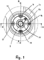
- the spindle pin 2 is provided with an axial cam groove 55 into which a torque take-off 56 (FIG. Fig. 1 ) intervenes. It is attached to the front side of the bearing hub 6.
- the threaded pin 45 has to be rotated with a corresponding tool in order to generate the clamping pressure in the pressure chamber 3.
- the threaded pin 45 is advantageously designed as Allen screw, which can be rotated about its axis with a corresponding key.
- the pressure gauge 15 can be a simple tension control make.
- the threaded pin 46 is merely turned back with the tool. The tool for rotating the threaded pin 45 can carry the user with him. When clamping and releasing process, no pressure medium escapes to the outside, so that a clean work is guaranteed.
- a possible leakage of the pressure medium can be compensated at any time by refilling the medium through the port 18, if it should be necessary.
- the clamping system described represents a closed system.
- the pressure medium is filled via the port 18 during the first filling by means of a high-pressure grease press. Since the bearing hub 6 has the pressure gauge 15, the grease gun need not have a pressure gauge, since the correct pressure is indicated by the pressure gauge 15. For initial filling of the system and for checking the correct display of the pressure gauge 15, however, a manometer is advantageous.
- the tool required for actuating the threaded pin 45 is necessary, which is for example an Allen wrench. It can also be used for other operations when setting up a machine. As a result, only a few tools are required to set up the machine.
- the pressure gauge 15 can be checked at any time, whether the voltage is still guaranteed with the desired clamping force. This is advisable daily and every time the machine is switched on. It eliminates the time-consuming handling of a grease gun, by means of which so far the correct voltage must be controlled. To do this, the grease gun must be connected to port 18 each time and pumped up to the desired pressure, which must be read via the pressure gauge.
- the closed system for clamping has been described on the basis of an abutment for a spindle journal 2. It is equally possible to use the described closed system for clamping tools on a spindle.
- the elements 15 to 18 are in the main body of the tool to which the required for the machining of workpieces knives and the like. Are attached.
Landscapes
- Engineering & Computer Science (AREA)
- Mechanical Engineering (AREA)
- Gripping On Spindles (AREA)
- Turning (AREA)
Abstract
Das Gegenlager ist für Bearbeitungsspindeln von Bearbeitungsmaschinen, insbesondere Holzbearbeitungsmaschinen, vorzugsweise Kehlmaschinen, vorgesehen. Es hat wenigstens eine Dehnbuchse, deren elastisch verformbare Wand wenigstens eine Druckkammer (3) begrenzt. Sie nimmt ein Druckmedium auf. In die Druckkammer (3) mündet eine Druckleitung (50), in der ein mechanisch mittels eines Werkzeuges betätigbares Druckelement (45) sitzt. Mit ihm ist ein das Druckmedium beaufschlagender Kolben (47) verschiebbar.

Description
Die Erfindung betrifft ein Gegenlager für Bearbeitungsspindeln von Bearbeitungsmaschinen nach dem Oberbegriff des Anspruches 1 sowie ein Verfahren zum Spannen von Gegenlagern und Werkzeugen auf Bearbeitungsspindeln von Bearbeitungsmaschinen nach dem Oberbegriff des Anspruches 13.The invention relates to an abutment for machining spindles of machine tools according to the preamble of claim 1 and a method for clamping of counter bearings and tools on machining spindles of machine tools according to the preamble of
Zum Spannen von Gegenlager auf Spindeln sind Spanneinrichtungen bekannt, die mit Dehnbuchsen versehen sind. Sie weisen jeweils eine elastisch verformbare Wand auf, die eine ringförmige Druckkammer begrenzt. In die Druckkammern wird ein Druckmedium, vorzugsweise Fett, mit Druck eingebracht. Soll das Gegenlager auf der Spindel gespannt werden, wird an einen entsprechenden Anschluss eine Hochdruckfettpresse angeschlossen, mit der das Fett in die Druckkammer mit hohem Druck gepumpt wird. Zum Lösen der Spannung wird ein Ventil geöffnet, über das ein Teil des Fettes abgelassen wird. Mit einer solchen Spanneinrichtung ist ein sauberes Arbeiten nicht möglich. Das Fett gelangt nicht nur beim Spannvorgang, sondern auch beim Lösevorgang nach außen und führt zu einer Verschmutzung. Zudem ist der Einsatz einer Hochdruckfettpresse zum Spannen des Gegenlagers auf der Spindel sehr aufwändig.For clamping abutment on spindles clamping devices are known, which are provided with expansion sleeves. They each have an elastically deformable wall which delimits an annular pressure chamber. In the pressure chambers, a pressure medium, preferably fat, introduced with pressure. If the counter bearing is to be clamped on the spindle, a high-pressure grease press is connected to a corresponding port, with which the grease is pumped into the pressure chamber at high pressure. To release the voltage, a valve is opened, through which a part of the grease is discharged. With such a clamping device a clean work is not possible. The grease not only reaches the outside during the clamping process but also during the dissolving process and leads to contamination. In addition, the use of a high pressure grease press for clamping the anvil on the spindle is very complex.
Der Erfindung liegt die Aufgabe zugrunde, das gattungsgemäße Gegenlager und das gattungsgemäße Verfahren so auszubilden, dass ein einfacher, zuverlässiger und sauberer Spann- sowie Lösevorgang möglich ist.The invention has the object of providing the generic counter bearing and the generic method in such a way that a simple, reliable and clean clamping and releasing operation is possible.
Diese Aufgabe wird beim gattungsgemäßen Gegenlager erfindungsgemäß mit den kennzeichnenden Merkmalen des Anspruches 1 und beim gattungsgemäßen Verfahren erfindungsgemäß mit den kennzeichnenden Merkmalen des Anspruches 13 gelöst.This object is achieved in the generic abutment according to the invention with the characterizing features of claim 1 and the generic method according to the invention with the characterizing features of
Das erfindungsmäße Gegenlager zeichnet sich durch ein geschlossenes System zum Spannen aus. Um das Druckmedium für den Spannvorgang unter Druck zu setzen, wird das Druckelement mittels eines Werkzeuges mechanisch betätigt, wodurch ein Kolben in Richtung auf die Druckkammer verschoben wird und das darin befindliche Druckmedium unter Druck setzt. Dadurch ist eine einfache und schnelle Spannung ohne Verwendung einer Fettpresse mit einem einfachen Werkzeug, wie beispielsweise einem Inbusschlüssel, möglich.The erfindungsmäße abutment is characterized by a closed system for clamping. In order to pressurize the printing medium for the clamping operation, the pressure element is mechanically actuated by means of a tool, whereby a piston is displaced in the direction of the pressure chamber and pressurizes the pressure medium located therein. As a result, a simple and fast tension without the use of a grease gun with a simple tool, such as an Allen key, possible.
Vorteilhaft sitzt das Druckelement in einer Gewindebohrung. Dadurch ist es möglich, das Druckelement stufenlos mit dem Werkzeug so zu drehen, dass der erforderliche Spanndruck erreicht wird. Soll die Spannung gelöst werden, wird das Druckelement zurückgedreht, wodurch der Kolben ebenfalls zurückgefahren und der auf das Druckmedium wirkende Druck verringert wird.Advantageously, the pressure element sits in a threaded hole. This makes it possible to steplessly rotate the pressure element with the tool so that the required clamping pressure is achieved. If the voltage to be released, the pressure element is rotated back, whereby the piston also retracted and the pressure acting on the pressure medium pressure is reduced.
Bei einer konstruktiv sehr einfachen Ausführungsform wird das Druckelement durch einen Gewindestift gebildet, der in die Gewindebohrung geschraubt ist.In a structurally very simple embodiment, the pressure element is formed by a threaded pin which is screwed into the threaded bore.
Damit das Druckmedium in der Druckkammer zuverlässig unter Druck gesetzt werden kann, ist der Kolben in einem Kolbenraum abgedichtet verschiebbar.Thus, the pressure medium in the pressure chamber can be reliably pressurized, the piston is sealed in a piston chamber displaced.
Vorteilhaft ist die Druckkammer mit einer Druckanzeige leitungsverbunden. Dadurch kann der Benutzer beim Einstellen des Spanndruckes sehr einfach feststellen, ob der notwenige Spanndruck erreicht wird.Advantageously, the pressure chamber is conductively connected to a pressure indicator. This allows the user when setting the clamping pressure very easily determine whether the necessary clamping pressure is achieved.
Die Druckanzeige weist in vorteilhafter Weise einen Stößel auf, der in einer in die Druckkammer mündenden Bohrung sitzt und abgedichtet in der Bohrung verschiebbar ist. Wird das Druckmedium mittels des Druckelementes in der Druckkammer unter Druck gesetzt, drückt das Medium auf die Stirnseite des Stößels, der als Kolben wirkt und der entsprechend dem aufgebrachten Druck verschoben wird. Dadurch kann über die Lage des Stößels sehr einfach festgestellt werden, ob der erforderliche Spanndruck erreicht ist.The pressure indicator advantageously has a plunger which sits in a bore opening into the pressure chamber and can be displaced in the bore in a sealed manner. If the pressure medium is pressurized by means of the pressure element in the pressure chamber, the medium presses on the end face of the tappet, which acts as a piston and which is displaced in accordance with the applied pressure. As a result, it can be very easily determined via the position of the plunger, whether the required clamping pressure is reached.
Der Stößel ist vorteilhaft in Richtung auf die Druckkammer federbelastet. Infolge der Federbelastung nimmt der Stößel, wenn das Druckmedium nicht unter Druck gesetzt ist, eine Ausgangsstellung ein. Beim Spannvorgang wird der Stößel gegen die Federbelastung verschoben, bis Kräftegleichgewicht zwischen der Kolbenkraft und der Federkraft herrscht.The plunger is advantageously spring-loaded in the direction of the pressure chamber. Due to the spring load, when the pressure medium is not pressurized, the plunger assumes a home position. During the clamping process, the plunger is moved against the spring load until equilibrium of forces between the piston force and the spring force prevails.
Vorteilhaft ist der Stößel von einem Tellerfederpaket umgeben. Es stützt sich mit dem einen Ende an einem stößelseitigen Anschlag und mit dem anderen Ende an einem Sicherungsteil ab. Da zum Spannen sehr hohe Drücke erforderlich sind, beispielsweise etwa 300 bar, ermöglicht das Tellerfederpaket entsprechend hohe, auf den Stößel in Richtung auf die Druckkammer wirkende Federkräfte.Advantageously, the plunger is surrounded by a plate spring package. It is supported at one end on a plunger-side stop and the other end on a securing part. Since for clamping very high pressures are required, for example, about 300 bar, the plate spring package allows correspondingly high, acting on the plunger in the direction of the pressure chamber spring forces.
Das Sicherungsteil zur Abstützung des Tellerfederpaketes ist bei einer konstruktiv einfachen Ausbildung eine Gewindehülse, die in eine Gewindebohrung geschraubt ist. Die Gewindehülse hat eine Durchgangsöffnung, in die der Stößel ragt. Für den Benutzer ist es auf diese Weise sehr einfach möglich, die Lage des Stößels in der Gewindehülse festzustellen. Die Abstimmung der Federkraft, insbesondere einer Tellerfederkraft, und die vom Druckmedium ausgeübte Kolbenkraft werden in vorteilhafter Weise so gewählt, dass bei Erreichen der Spannkraft die Stirnseite des Stößels in Höhe der Stirnseite der Gewindehülse liegt. Diese Lage des Stößels, der in der Ausgangsstellung noch innerhalb der Gewindehülse liegt, kann vom Benutzer zuverlässig erkannt werden.The securing part for supporting the cup spring assembly is in a structurally simple design a threaded sleeve which is screwed into a threaded bore. The threaded sleeve has a passage opening into which the plunger protrudes. For the user, it is very easy to determine the position of the plunger in the threaded sleeve in this way. The vote of the spring force, in particular a cup spring force, and the force exerted by the pressure medium piston force are selected in an advantageous manner so that upon reaching the clamping force, the end face of the plunger in height of the end face of the threaded sleeve lies. This position of the plunger, which is still in the initial position within the threaded sleeve can be reliably detected by the user.
Die Dehnbuchse ist bei einer vorteilhaften Ausführungsform in einer Lagernabe des Gegenlagers angeordnet.The expansion sleeve is arranged in an advantageous embodiment in a bearing hub of the abutment.
Es ist aber auch möglich, die Dehnbuchse in einem Werkzeug vorzusehen, um das Werkzeug auf einer Spindel zu befestigen.But it is also possible to provide the expansion sleeve in a tool to secure the tool on a spindle.
In beiden Fällen ermöglicht das geschlossene System ein sauberes und zuverlässiges Spannen der Lagernabe des Gegenlagers bzw. des Werkzeuges auf der Spindel.In both cases, the closed system allows a clean and reliable clamping of the bearing hub of the abutment or the tool on the spindle.
Für die Erstbefüllung der Druckkammer ist die Spanneinrichtung mit einem Anschluss versehen, über den das Druckmedium in die Druckkammer eingebracht werden kann.For the initial filling of the pressure chamber, the clamping device is provided with a connection, via which the pressure medium can be introduced into the pressure chamber.
Vorteilhaft ist die Druckkammer mit einem Druckablassventil leitungsverbunden.Advantageously, the pressure chamber is conductively connected to a pressure relief valve.
Beim erfindungsgemäßen Verfahren erfolgt zunächst eine Erstbefüllung mit dem Druckmedium. Auf diese Weise wird ein geschlossenes Spannsystem erhalten, mit dem Gegenlager oder auch Werkzeuge anschließend einfach dadurch gespannt werden können, dass das Druckmedium mittels des Kolbens mechanisch unter Druck gesetzt wird. Der Kolben wird hierbei durch ein Druckelement verschoben, um das Druckmedium unter den entsprechenden Druck zu setzen. Mit der Druckanzeige wird hierbei die Einstellung des Spanndruckes angezeigt und kann damit vom Anwender kontrolliert bzw. überwacht werden. Soll die Spannung aufgehoben werden, wird das Druckelement lediglich mechanisch in umgekehrter Richtung bewegt, so dass der Kolben unter dem Druck des Druckmediums zurückgeschoben wird.In the method according to the invention initially takes place first filling with the pressure medium. In this way, a closed clamping system is obtained, with the counter-bearing or tools can then be simply clamped by the fact that the pressure medium is mechanically pressurized by means of the piston. The piston is thereby displaced by a pressure element to put the pressure medium under the appropriate pressure. The pressure display shows the setting of the clamping pressure and can thus be checked or monitored by the user. If the voltage is canceled, the pressure element is only mechanically moved in the reverse direction, so that the piston is pushed back under the pressure of the pressure medium.
Vorteilhaft wird als Druckelement ein Schraubteil, wie ein Gewindestift, verwendet. Mit ihm kann der Kolben stufenlos verschoben werden, so dass der Spanndruck exakt eingestellt werden kann. Zum Betätigen des Schraubteiles ist nur ein einfaches Werkzeug, wie beispielsweise ein Inbusschlüssel, erforderlich.Advantageously, a screw, such as a threaded pin used as a pressure element. With it, the piston can be moved continuously, so that the clamping pressure can be set exactly. To operate the screw is only a simple tool, such as an Allen key required.
Als Druckanzeige wird vorteilhaft ein Stößel verwendet, der als ein durch das Druckmedium belasteter Kolben wirkt, der gegen Federkraft durch das Druckmedium beim Spannvorgang verschoben wird. Die Federkraft sorgt auch dafür, dass der Stößel beim Lösen der Spannung wieder zurückgeschoben wird.As a pressure indicator, a plunger is advantageously used, which acts as a loaded by the pressure medium piston, which is displaced against spring force by the pressure medium during the clamping operation. The spring force also ensures that the plunger is pushed back when releasing the voltage.
Der Anmeldungsgegenstand ergibt sich nicht nur aus dem Gegenstand der einzelnen Patentansprüche, sondern auch durch alle in den Zeichnungen und der Beschreibung offenbarten Angaben und Merkmale. Sie werden, auch wenn sie nicht Gegenstand der Ansprüche sind, als erfindungswesentlich beansprucht, soweit sie einzeln oder in Kombination gegenüber dem Stand der Technik neu sind.The subject of the application results not only from the subject matter of the individual claims, but also by all the information and features disclosed in the drawings and the description. They are, even if they are not the subject of the claims, claimed as essential to the invention, as far as they are new individually or in combination over the prior art.
Weitere Merkmale der Erfindung ergeben sich aus den weiteren Ansprüchen, der Beschreibung und den Zeichnungen.Further features of the invention will become apparent from the other claims, the description and the drawings.
Die Erfindung wird nachstehend anhand eines in den Zeichnungen dargestellten Ausführungsbeispieles näher erläutert. Es zeigen
- Fig. 1
- eine Stirnansicht einer erfindungsgemäßen Spanneinrichtung,
- Fig. 2
- einen Schnitt längs der Linie A - A in
Fig.1 , - Fig. 3
- einen Schnitt längs der Linie B - B in
Fig. 1 , - Fig. 4
- die Einzelheit C in
Fig. 2 in vergrößerter Darstellung.
- Fig. 1
- an end view of a clamping device according to the invention,
- Fig. 2
- a section along the line A - A in
Fig.1 . - Fig. 3
- a section along the line B - B in
Fig. 1 . - Fig. 4
- the detail C in
Fig. 2 in an enlarged view.
Die Spanneinrichtung ist im dargestellten Ausführungsbeispiel Teil eines Gegenlagers, das eine spielfreie und zentrische Verbindung mit der Spindel ermöglicht. Es hat eine Hydrodehnbuchse 1 (
Die Hydrodehnbuchse 1 ist in einer Durchgangsöffnung 5 einer Lagernabe 6 untergebracht. Die Durchgangsöffnung 5 wird von einer Wand 7 begrenzt, die mit einer Ringschulter 8 versehen ist, an der die Hydrodehnbuchse 1 in einer Achsrichtung abgestützt ist. Hierzu ist die Hydrodehnbuchse 1 an einem Ende mit einem vorstehenden Radialflansch 9 versehen, mit dem die Hydrodehnbuchse 1 an der Ringschulter 8 axial abgestützt ist. Beiderseits der ringförmigen Druckkammer 3 befinden sich Dichtringe 10, 11, vorzugsweise O-Ringe, die in Ringnuten 12, 13 am Außenumfang der Hydrodehnbuchse 1 eingelegt sind und die Abdichtung zwischen der Hydrodehnbuchse und der Lagernabe 6 gewährleisten.The hydraulic expansion bushing 1 is accommodated in a
Die Druckkammer 3 ist ausreichend lang, um den Spindelzapfen 2 sicher spannen zu können. Er ragt mit seinen beiden Enden über die Lagernabe 6 vor und weist an seinem in
Die Hydrodehnbuchse 1 schließt mit ihrem einen Ende bündig mit einer Außenseite 14 der Lagernabe 6 ab, während das andere, den Radialflansch 9 aufweisende Ende innerhalb der Durchgangsöffnung 5 liegt.The hydraulic expansion bushing 1 ends with its one end flush with an
Die Lagernabe 6 ist mit einer Druckanzeige 15 und einem Druckerzeuger 16 versehen, mit dem das in der Druckkammer 3 befindliche Druckmedium unter Druck gesetzt werden kann.The bearing
Die Lagernabe 6 ist außerdem mit einem Ventil 17 für die Entlüftung bei der Erstbefüllung mit Druckmedium und für den Druckablass in der Druckkammer 3 und mit einem Anschluss 18 versehen (
Wie aus
Die Lagernabe 6 ist im Bereich der Teile 15 bis 18 vorteilhaft verbreitert ausgebildet, so dass ausreichend Einbauraum für diese Teile zur Verfügung steht. Die Verbreiterung wird durch einen Ringflansch 19 gebildet, der nahe dem einen Ende der Lagernabe 6 vorgesehen ist und radial von einem buchsenförmigen Grundkörper 20 der Lagernabe absteht. Der Grundkörper 20 weist die Durchgangsöffnung 5 zur Aufnahme der Hydrodehnbuchse 1 auf.The bearing
Die Lagernabe 6 ist von einer Schiebebuche 22 umgeben, die die Lagernabe 6 nahezu über deren gesamte Länge umgibt. Die Schiebebuchse 22 ist innenseitig mit einem radial vorstehenden Ring 23 versehen, mit dem die Schiebebuchse 22 den Ringflansch 19 der Lagernabe 6 hintergreift. Die Schiebebuchse 22 ist im Ausführungsbeispiel an einer Aufnahmeplatte 24 axial verschiebbar gehalten und wird bei einer Axialverstellung der Spindel mit dieser axial mitbewegt. Die Aufnahmeplatte 24 wird vorteilhaft an einer Gegenlagerplatte befestigt, welche wiederum am Maschinenständer angeordnet ist.The bearing
Auf der von den Teilen 15 bis 18 abgewandten Seite des Ringes 23 befindet sich wenigstens ein Drehlager 25, das im Ausführungsbeispiel als Wälzlager ausgebildet ist. Mit dem Drehlager 25 ist die Lagernabe 6 drehbar in der Schiebebuchse 22 gelagert.On the side facing away from the
Das Drehlager 25 wird mittels eines Spannringes 26 gegen eine Ringschulter 27 an der Außenseite des Grundkörpers 20 axial gespannt. Der Spannring 26 wird auf das in den
Zwischen dem Spannring 26 und dem Drehlager 25 liegt ein Dichtring 28, dessen äußerer Rand mit Schrauben 29 an der Stirnseite der Schiebebuchse 22 befestigt ist. Der Dichtring 28 und der Spannring 26 sind so ausgebildet, dass sie eine vor dem Drehlager 25 liegende Labyrinthdichtung bilden. Der Dichtring 28 hat eine radial nach außen abstehende Ringschulter 61, die zusammen mit einer gegenüberliegend an der Schiebebuchse 22 angeordneten Ringschulter 62 einen axialen Verschiebebereich der Schiebebuchse 22 in der Aufnahmeplatte 24 festlegt. Damit ist zusätzlich verhindert, dass das Gegenlager aus der Aufnahmeplatte 24 herausfallen kann.Between the clamping
Die Druckanzeige 15 (
Der Stößel 30 ragt in eine Bohrung 34, die im Grundkörper 20 der Lagernabe 6 vorgesehen ist und in die Druckkammer 3 mündet (
Der Stößel 30 ist im Bereich außerhalb der Bohrung 34 von wenigstens einer Druckfeder 36 umgeben, die im Ausführungsbeispiel durch ein Tellerfederpaket gebildet wird, wobei die einzelnen Tellerfedern aufeinander gestapelt und die Stapel gegensinnig zueinander ausgerichtet sind. Das der Gewindehülse 32 zugewandte Ende der Druckfeder 36 ist unter Zwischenlage einer Distanzscheibe 37 an der Gewindehülse 32 abgestützt. Das andere Ende der Druckfeder 36 liegt an einem Absatz 38 an (
Die Druckfeder 36 liegt in einem Aufnahmeraum 41, der im Bereich des Ringflansches 19 der Lagernabe 6 vorgesehen ist und größeren Durchmesser hat als die in ihn mündende Bohrung 34 und der sich nach außen hin in der Gewindebohrung 33 fortsetzt.The
Die Distanzscheibe 37 dient zum Ausgleich von Federtoleranzen, so dass die noch zu beschreibende Funktion des Stößels 30 jederzeit gewährleistet ist.The
Der Stößelteil 40, der in die Bohrung 34 ragt, bildet einen Kolben, der durch das in der Druckkammer 3 befindliche, unter Druck stehende Medium belastet wird.The
Wird die Druckkammer 3 mit dem Medium, in der Regel Hydraulikfett, gefüllt und unter Druck gesetzt, wird der Stößel 30 nach außen belastet. Durch die auf den Kolben 40 wirkende Kraft des Druckmediums wird der Stößel 30 so weit verschoben, bis ein Kräftegleichgewicht zwischen der auf den Kolben 40 wirkenden Kraft und der entgegenwirkenden Kraft der Druckfeder 36 besteht. Die Abstimmung der Federkraft ist vorteilhaft so gewählt, dass im gespannten Zustand der Stößel 30 mit seiner Stirnseite 42 bündig mit der Stirnseite 43 der Gewindehülse 32 ist. Dann ist der Druck in der Druckkammer 3 ausreichend hoch, um den Spindelzapfen 2 sicher zu spannen. Da der endseitige Stößelteil 40 abgedichtet in der Bohrung 34 geführt ist, ist eine zuverlässige Druckanzeige durch den Stößel 30 sichergestellt.If the
Die Druckanzeige kann auch durch eine Markierung am Stößel 30 erfolgen, wie eine Ringnut, eine Markierung und dergleichen.The pressure indication can also be done by a mark on the
Der Druckerzeuger 16 hat einen in eine Gewindebohrung 44 geschraubten Gewindestift 55 (
Die Gewindebohrung 44 mündet in die Stirnseite 21 des Ringflansches 19 der Lagernabe 6. Mit dem Gewindestift 45 kann der Kolben 46 im Kolbenraum 48 verstellt werden. Der Kolben 46 kann auch lösbar mit dem Gewindestift 45 verbunden oder einstückig mit ihm ausgebildet sein.The threaded bore 44 opens into the
In den Boden 49 des Kolbenraumes 48 mündet eine Bohrung 50, die den Kolbenraum 48 mit der Druckkammer 3 verbindet. Die Bohrung 50, die im Grundkörper 20 der Lagernabe 6 vorgesehen ist, hat kleineren Durchmesser als der Kolbenraum 48, der im Wesentlichen im Bereich des Ringflansches 19 vorgesehen ist.In the bottom 49 of the
Der Gewindestift 45 ragt vorteilhaft über die Stirnseite 21 des Ringflansches 19, so dass der Gewindestift 45 mit einem entsprechenden Werkzeug bequem verstellt werden kann.The threaded
Vorteilhaft überragt die Schiebebuche 22 den Ringflansch 19 axial so weit, dass die Schiebebuchse 22 den Gewindestift 45 axial überragt.Advantageously, the sliding
Mit dem Gewindestift 45 wird das in der Druckkammer 3 befindliche Medium unter Druck gesetzt, indem durch Drehen des Gewindestiftes 45 der Kolben 47 nach innen bewegt wird. Das Druckmedium befindet sich nicht nur in der Druckkammer 3, sondern auch in den Bohrungen 34, 50 und im Kolbenraum 48, so dass geringe Verstellwege des Kolbens 46 ausreichen, das Medium unter Druck zu setzen. Durch Drehen des Gewindestiftes 45 beim Spannvorgang wird der Stößel 30 der Druckanzeige 15 aus seiner in
Zum Befüllen der Druckkammer 3 mit dem Druckmedium dient der Anschluss 18 (
An den Anschluss 18 wird beispielhaft eine Hochdruckfettpresse angeschlossen, über die das unter Druck zu setzende Fett als Druckmedium in die Druckkammer 3 gefüllt wird.To the terminal 18, for example, a high pressure grease press is connected, via which the fat to be placed under pressure is filled as a pressure medium in the
Das Druckablassventil 17 ist ebenfalls in der Stirnseite 21 des Ringflansches 19 vorgesehen. Es dient primär zur Entlüftung bei der Befüllung mit Druckmedium. Mit dem Ventil 17 kann bei Bedarf auch der Druck abgebaut werden, indem beim Öffnen eine geringe Menge an Druckmedium nach außen treten kann.The
Bei der Erstbefüllung wird der Gewindestift 45 so weit eingeschraubt, dass der Kolben 46 am Boden 49 des Kolbenraumes 48 anliegt. Über den Anschluss 18 wird mittels der Hochdruckfettpresse das Druckmedium zunächst bei geöffnetem Druckablassventil 17 eingefüllt, bis das System entlüftet, das heißt komplett mit Fett befüllt ist. Danach wird das Druckablassventil 17 geschlossen und das Druckmedium so weit eingefüllt, bis der Stößel 30 mit seiner Stirnseite 42 bündig mit der Stirnseite 43 der Gewindehülse 32 liegt. Hat die Hochdruckfettpresse selbst ein Manometer, dann kann über das Manometer der Druck abgelesen werden. Zum Entspannen kann nun der Gewindestift 45 so weit zurückgedreht werden, bis der Druck abgebaut ist. Die nachfolgenden Spannvorgänge erfolgen immer in der Weise, dass der Gewindestift 45 bis auf Anschlag eingeschraubt wird, womit automatisch der richtige Spanndruck aufgebaut wird. Dieser wird durch die Druckanzeige angezeigt und durch den Bediener kontrolliert.When first filling the threaded
Der Befüllvorgang kann auch so durchgeführt werden, dass der Gewindestift 45 in seine andere Endlage zurückgeschraubt wird. Die Befüllung mit dem Druckmedium erfolgt in diesem Falle ohne Druckaufbau. Sobald der Befüllvorgang abgeschlossen ist, wird der Gewindestift 45 in die Gewindebohrung 44 geschraubt, so dass der Kolben 46 das Druckmedium unter Druck setzt. Der Gewindestift 45 wird so weit eingeschraubt, bis der korrekte Spanndruck an der Druckanzeige 15 angezeigt wird.The filling process can also be carried out so that the threaded
Der Spindelzapfen 2 ist mit einer axialen Mitnehmernut 55 versehen, in die eine Drehmomentmitnahme 56 (
Mit dem beschriebenen Gegenlager ist eine einfache und schnelle Montage möglich. Zur Druckerzeugung muss lediglich der Gewindestift 45 mit einem entsprechenden Werkzeug gedreht werden, um den Spanndruck in der Druckkammer 3 zu erzeugen. Der Gewindestift 45 ist vorteilhaft als Inbusschraube ausgebildet, die mit einem entsprechenden Schlüssel um ihre Achse gedreht werden kann. Mittels der Druckanzeige 15 lässt sich eine einfache Spannkontrolle vornehmen. Zum Lösen der Spannung wird der Gewindestift 46 mit dem Werkzeug lediglich zurückgedreht. Das Werkzeug zum Drehen des Gewindestiftes 45 kann der Anwender bei sich tragen. Beim Spann- und Lösevorgang tritt kein Druckmedium nach außen, so dass ein sauberes Arbeiten gewährleistet ist.With the abutment described a simple and quick installation is possible. To generate pressure, only the threaded
Eine mögliche Leckage des Druckmediums lässt sich jederzeit durch Nachfüllen des Mediums über den Anschluss 18 ausgleichen, wenn es erforderlich sein sollte.A possible leakage of the pressure medium can be compensated at any time by refilling the medium through the
Geringfügige Leckagen können durch den Stößel 30 ausgeglichen werden. Da er mittels der Druckfeder 36 vorgespannt ist, wird der Stößel 30 bei geringen Leckagen durch die Druckfeder 36 so nachgestellt, dass ein zum sicheren Spannen ausreichender Druck erhalten bleibt.Minor leaks can be compensated by the
Das beschriebene Spannsystem stellt ein geschlossenes System dar. Das Druckmedium wird bei der Erstbefüllung mittels einer Hochdruckfettpresse über den Anschluss 18 eingefüllt. Da die Lagernabe 6 die Druckanzeige 15 aufweist, muss die Fettpresse ein Druckmanometer nicht aufweisen, da der korrekte Druck durch die Druckanzeige 15 angezeigt wird. Für die Erstbefüllung des Systems und zur Kontrolle der richtigen Anzeige der Druckanzeige 15 ist allerdings ein Manometer vorteilhaft.The clamping system described represents a closed system. The pressure medium is filled via the
Zum Spannen und Lösen des Spindelzapfens 2 ist nur noch das zum Betätigen des Gewindestiftes 45 erforderliche Werkzeug notwendig, das beispielsweise ein Inbusschlüssel ist. Er kann auch für andere Betätigungen beim Rüsten einer Maschine eingesetzt werden. Dadurch sind zum Rüsten der Maschine nur noch wenige Werkzeuge notwendig.For clamping and releasing the
Durch die Druckanzeige 15 kann jederzeit kontrolliert werden, ob die Spannung mit der gewünschten Spannkraft noch gewährleistet ist. Dies ist täglich und nach jedem Einschalten der Maschine ratsam. Es entfällt hierbei die aufwändige Handhabung einer Fettpresse, mittels derer bisher die noch richtige Spannung kontrolliert werden muss. Dazu muss die Fettpresse jedes Mal an den Anschluss 18 angeschlossen und mit dem gewünschten Druck, der über das Manometer abgelesen werden muss, aufgepumpt werden.By the
Das geschlossene System zum Spannen ist anhand eines Gegenlagers für einen Spindelzapfen 2 beschrieben worden. Es ist in gleicher Weise möglich, das beschriebene geschlossene System zum Spannen von Werkzeugen auf einer Spindel einzusetzen. In diesem Falle befinden sich die Elemente 15 bis 18 im Grundkörper des Werkzeuges, an dem die zur Bearbeitung von Werkstücken erforderlichen Messer und dgl. befestigt sind.The closed system for clamping has been described on the basis of an abutment for a
Da Werkzeuge je nach Drehrichtung in unterschiedlichen Ausrichtungen auf den Bearbeitungsspindeln montiert werden, weisen diese vorteilhaft an beiden Stirnseiten die Druckanzeige 15 und den Druckerzeuger 16 auf, die jeweils mit der Druckkammer 3 verbunden sind. Lange Werkzeuge können auch mit jeweils einer Dehnbuchse an den gegenüberliegenden Seiten ausgeführt sein. Hier sind die Druckkammern 3 der beiden Dehnbuchsen 1 sowie die beidseitigen stirnseitigen Druckanzeigen 15 und Druckerzeuger 16 über Bohrungen im Werkzeuggrundkörper miteinander verbunden, so dass auch hier nur ein geschlossenes System vorhanden ist. Es ist nicht notwendig, den Anschluss 18 zum Befüllen und das Druckablassventil 17 an beiden Stirnseiten vorzusehen. Es ist ausreichend, dies an einer Stirnseite oder vorteilhaft am Umfang des Werkzeuggrundkörpers anzuordnen, da diese nicht für die normale Werkzeugspannung gebraucht werden, sondern nur für die Erstbefüllung und bei Bedarf für eine spätere Nachbefüllung oder Nachkontrolle.Since tools are mounted depending on the direction of rotation in different orientations on the machining spindles, they have advantageous at both ends of the
Claims (16)
dadurch gekennzeichnet, dass in die Druckkammer (3) eine Druckleitung (50) mündet, in der ein mechanisch mittels eines Werkzeuges betätigbares Druckelement (45) sitzt, mit dem ein das Druckmedium beaufschlagender Kolben (47) verschiebbar ist.Counter bearing for processing spindles of processing machines, in particular woodworking machines, preferably moulders, with at least one expansion sleeve whose elastically deformable wall delimits at least one pressure chamber, which receives a pressure medium and into which a supply line for the pressure medium opens,
characterized in that in the pressure chamber (3) a pressure line (50) opens, in which a mechanically actuated by a tool pressure element (45) sits, with which a pressure medium acting on the piston (47) is displaceable.
dadurch gekennzeichnet, dass das Druckelement (45) in einer Gewindebohrung (44) sitzt.An abutment according to claim 1,
characterized in that the pressure element (45) in a threaded bore (44) sits.
dadurch gekennzeichnet, dass das Druckelement (45) ein Gewindestift ist.An abutment according to claim 1 or 2,
characterized in that the pressure element (45) is a threaded pin.
dadurch gekennzeichnet, dass der Kolben (47) abgedichtet in einem Kolbenraum (48) verschiebbar ist.An abutment according to one of claims 1 to 3,
characterized in that the piston (47) sealed in a piston chamber (48) is displaceable.
dadurch gekennzeichnet, dass die Druckkammer (3) mit einer Druckanzeige (15) leitungsverbunden ist.An abutment according to one of claims 1 to 4,
characterized in that the pressure chamber (3) is conductively connected to a pressure indicator (15).
dadurch gekennzeichnet, dass die Druckanzeige (15) einen Stößel (30) aufweist, der in einer in die Druckkammer (3) mündenden Bohrung (34) sitzt und abgedichtet in der Bohrung (34) verschiebbar ist.An abutment according to claim 4,
characterized in that the pressure indicator (15) has a plunger (30) which sits in a in the pressure chamber (3) opening bore (34) and sealed in the bore (34) is displaceable.
dadurch gekennzeichnet, dass der Stößel (30) in Richtung auf die Druckkammer (3) federbelastet ist.An abutment according to claim 6,
characterized in that the plunger (30) is spring-loaded in the direction of the pressure chamber (3).
dadurch gekennzeichnet, dass der Stößel (30) von einem Tellerfederpaket (36) umgeben ist, das mit dem einen Ende an einem stößelseitigen Anschlag (38) und mit dem anderen Ende an einem Sicherungsteil (32) abgestützt ist.An abutment according to claim 6 or 7,
characterized in that the plunger (30) by a disc spring assembly (36) is surrounded, which is supported with one end to a plunger-side stop (38) and with the other end to a securing part (32).
dadurch gekennzeichnet, dass das Sicherungsteil (32) eine Gewindehülse ist, die in eine Gewindebohrung (33) geschraubt ist und eine Durchgangsöffnung (31) aufweist, in die der Stößel (30) ragt.An abutment according to claim 8,
characterized in that the securing part (32) is a threaded sleeve which is screwed into a threaded bore (33) and has a passage opening (31) into which the plunger (30) protrudes.
dadurch gekennzeichnet, dass die Dehnbuchse (19 in einer Lagernabe (6) des Gegenlagers angeordnet ist.An abutment according to one of claims 1 to 9,
characterized in that the expansion bushing (19 in a bearing hub (6) of the anvil is arranged.
dadurch gekennzeichnet, dass die Dehnbuchse 19 in einem Werkzeug angeordnet ist.An abutment according to one of claims 1 to 9,
characterized in that the expansion sleeve 19 is arranged in a tool.
dadurch gekennzeichnet, dass die Druckkammer (3) mit einem
Anschluss (18) zum Befüllen der Druckkammer mit dem Druckmedium leitungsverbunden ist.An abutment according to one of claims 1 to 11,
characterized in that the pressure chamber (3) with a
Connection (18) for filling the pressure chamber is conductively connected to the pressure medium.
dadurch gekennzeichnet, dass die Druckkammer (3) mit einem Druckablassventil (17) leitungsverbunden ist.An abutment according to one of claims 1 to 11,
characterized in that the pressure chamber (3) with a pressure relief valve (17) is conductively connected.
dadurch gekennzeichnet, dass das Druckelement (45) ein Schraubteil ist.Method according to claim 14,
characterized in that the pressure element (45) is a screw member.
dadurch gekennzeichnet, dass die Druckanzeige (15) einen durch das Druckmedium belasteten, als Kolben wirkenden Stößel (30) aufweist, der gegen Federkraft durch das Druckmedium verschoben wird.Method according to claim 13 or 14,
characterized in that the pressure indicator (15) has a loaded by the pressure medium, acting as a piston plunger (30) which is displaced against spring force by the pressure medium.
Applications Claiming Priority (1)
| Application Number | Priority Date | Filing Date | Title |
|---|---|---|---|
| DE102017004994.7A DE102017004994A1 (en) | 2017-05-17 | 2017-05-17 | Counter bearing for machining spindles of machine tools and method for clamping counter bearings and tools |
Publications (1)
| Publication Number | Publication Date |
|---|---|
| EP3403749A1 true EP3403749A1 (en) | 2018-11-21 |
Family
ID=62492373
Family Applications (1)
| Application Number | Title | Priority Date | Filing Date |
|---|---|---|---|
| EP18000450.9A Pending EP3403749A1 (en) | 2017-05-17 | 2018-05-14 | Counterbearing for machining spindles of operating machines and method of clamping counterbearings and tools |
Country Status (3)
| Country | Link |
|---|---|
| US (1) | US10821523B2 (en) |
| EP (1) | EP3403749A1 (en) |
| DE (1) | DE102017004994A1 (en) |
Families Citing this family (4)
| Publication number | Priority date | Publication date | Assignee | Title |
|---|---|---|---|---|
| DE102018214190A1 (en) * | 2018-08-22 | 2020-02-27 | Gühring KG | Hydraulic chucks |
| DE102018214189A1 (en) * | 2018-08-22 | 2020-02-27 | Gühring KG | expansion chucks |
| EP4032644A4 (en) * | 2019-09-20 | 2023-06-07 | Big Daishowa Co., Ltd. | Hydrochuck |
| CN110977518B (en) * | 2019-11-20 | 2020-12-22 | 中国航发沈阳黎明航空发动机有限责任公司 | Manufacturing precision adjusting method based on zero locator tool |
Citations (5)
| Publication number | Priority date | Publication date | Assignee | Title |
|---|---|---|---|---|
| DE2424593B1 (en) * | 1974-05-21 | 1975-10-30 | Friedrich Deckel Ag, 8000 Muenchen | Device for clamping a drilling spindle arranged in the milling spindle of a machine tool |
| US4533287A (en) * | 1981-10-09 | 1985-08-06 | Ex-Cell-O Corporation | Cutter head with locking pressure indicator |
| DE4012980A1 (en) * | 1990-04-24 | 1991-10-31 | Schrem Werkzeugfab Albert | Hydraulic clamping nut for rotating tool - has interconnected cylinders for clamping pistons |
| DE4224872A1 (en) * | 1992-07-28 | 1994-02-03 | Weinig Michael Ag | Clamp for clamping planing cutter on arbor - consists of clamping bushes in cutter bore which clamp onto arbor when closed hydraulic circuit is pressurised by contact of piston with arbor nut |
| KR101594627B1 (en) * | 2009-12-17 | 2016-02-16 | 두산인프라코어 주식회사 | Spindle support apparatus for a machine tool |
Family Cites Families (15)
| Publication number | Priority date | Publication date | Assignee | Title |
|---|---|---|---|---|
| US3250542A (en) * | 1964-05-04 | 1966-05-10 | Erickson Tool Co | Hydraulic chucks and arbors |
| US3388917A (en) * | 1966-03-14 | 1968-06-18 | Erickson Tool Co | Hydraulic chucks and arbors |
| US3592482A (en) * | 1968-05-27 | 1971-07-13 | Scully Jones Co | Hydraulic chuck |
| US3770287A (en) * | 1972-01-13 | 1973-11-06 | Positrol Inc | Hydraulically controlled holding device |
| US4147312A (en) * | 1977-09-22 | 1979-04-03 | Great Lakes Industries, Inc. | Gas-liquid hydraulic expandable chucks and shafts |
| DE3213483A1 (en) * | 1982-04-10 | 1983-10-13 | Albert Schrem Werkzeugfabrik GmbH, 7928 Giengen | HYDRAULIC TENSION NUT |
| DE3422000A1 (en) * | 1984-06-14 | 1985-12-19 | Albert Schrem Werkzeugfabrik GmbH, 7928 Giengen | PRESSURE-OPERATED CLAMPING DEVICE FOR CLAMPING TOOLS OR WORKPIECES |
| US5388487A (en) * | 1990-10-17 | 1995-02-14 | Sandvik Ab | Hydraulic tool holder with coolant jets |
| US5141370A (en) * | 1990-12-06 | 1992-08-25 | Carrier Corporation | High precision tool holder |
| US5221098A (en) * | 1991-11-05 | 1993-06-22 | Hardinge Brothers, Inc. | Collet closer |
| DE4317502A1 (en) * | 1993-05-26 | 1994-12-01 | Schrem Werkzeugfab Albert | Hydraulic tensioning element |
| US6299179B1 (en) * | 1995-03-22 | 2001-10-09 | R. S. R. Adtec Ltd. | Fluid actuated chuck |
| DE202004005321U1 (en) * | 2004-04-03 | 2005-08-11 | Kennametal Inc. | Hydraulic expansion chuck |
| DE102008008855A1 (en) * | 2008-02-13 | 2009-08-20 | Schaeffler Kg | bearing arrangement |
| DE102010032284A1 (en) * | 2010-07-26 | 2012-01-26 | Rainer Pfister | Hydraulic expansion |
-
2017
- 2017-05-17 DE DE102017004994.7A patent/DE102017004994A1/en active Pending
-
2018
- 2018-05-14 EP EP18000450.9A patent/EP3403749A1/en active Pending
- 2018-05-17 US US15/981,944 patent/US10821523B2/en active Active
Patent Citations (5)
| Publication number | Priority date | Publication date | Assignee | Title |
|---|---|---|---|---|
| DE2424593B1 (en) * | 1974-05-21 | 1975-10-30 | Friedrich Deckel Ag, 8000 Muenchen | Device for clamping a drilling spindle arranged in the milling spindle of a machine tool |
| US4533287A (en) * | 1981-10-09 | 1985-08-06 | Ex-Cell-O Corporation | Cutter head with locking pressure indicator |
| DE4012980A1 (en) * | 1990-04-24 | 1991-10-31 | Schrem Werkzeugfab Albert | Hydraulic clamping nut for rotating tool - has interconnected cylinders for clamping pistons |
| DE4224872A1 (en) * | 1992-07-28 | 1994-02-03 | Weinig Michael Ag | Clamp for clamping planing cutter on arbor - consists of clamping bushes in cutter bore which clamp onto arbor when closed hydraulic circuit is pressurised by contact of piston with arbor nut |
| KR101594627B1 (en) * | 2009-12-17 | 2016-02-16 | 두산인프라코어 주식회사 | Spindle support apparatus for a machine tool |
Also Published As
| Publication number | Publication date |
|---|---|
| US10821523B2 (en) | 2020-11-03 |
| US20180333787A1 (en) | 2018-11-22 |
| DE102017004994A1 (en) | 2018-11-22 |
Similar Documents
| Publication | Publication Date | Title |
|---|---|---|
| EP3403749A1 (en) | Counterbearing for machining spindles of operating machines and method of clamping counterbearings and tools | |
| DE102013003053B4 (en) | Clamping device and method for clamping workpieces with axially displaceable clamping screw in axially displaceable plunger | |
| DE69800037T2 (en) | Chuck | |
| EP0855243A2 (en) | Clamping arrangement, particularly for workpieces | |
| EP2353774B1 (en) | Clamping device with height compensation | |
| DE102009041907B4 (en) | Brake and / or clamping device with dimensionally stable central body | |
| DE2520889A1 (en) | TWO-WAY SHUT-OFF VALVE, IN PARTICULAR FOR PNEUMATIC VEHICLE BRAKING SYSTEMS | |
| EP2832478B1 (en) | Connection system and intermediate bush and kit with an intermediate bush and a detent bolt for use in such a connection system | |
| DE3422000A1 (en) | PRESSURE-OPERATED CLAMPING DEVICE FOR CLAMPING TOOLS OR WORKPIECES | |
| EP0991872B1 (en) | Fastening device | |
| EP0252208B2 (en) | Pressure fluid driven cylinder | |
| DE102007031463A1 (en) | Pressurized medium cylinder e.g. simple-working pressurized medium cylinder, for use in e.g. quick-action clamping cylinder, has locking unit for locking piston in one of end positions or intermediate position between end positions | |
| DE4339755C1 (en) | Arrangement for making holes in a dish or a rim of a wheel of a motor vehicle | |
| DE2854121C2 (en) | A device that can be attached to a machine part for cutting out ring lips in bearing bushes mortised in bores there | |
| DE102017000671B4 (en) | Lathe chuck and machine tool | |
| DE1966073B2 (en) | Pressure medium transmitter on a machine tool or the like | |
| EP0366105A2 (en) | Tool-clamping device, especially for grinding wheels | |
| WO2019020783A1 (en) | Adjusting device for a cutting tool and cutting tool having an adjusting device | |
| EP2008748A2 (en) | Collet chuck | |
| DE3413285A1 (en) | CLAMPING DEVICE FOR TOOLS LIKE DRILLING, MILLING OR THE LIKE | |
| EP3403766A1 (en) | Clamping device for at least one component to be clamped | |
| DE1945866A1 (en) | Line coupling for connecting two lines | |
| DE10125154A1 (en) | Assembly to clamp a cutting/grinding tool has a clamping sleeve within a cylindrical holder, pressed against the tool sleeve/shaft by a pressure flow medium through axial drillings | |
| DE1222755B (en) | Clamping device | |
| DE2626557C3 (en) | Clamping device, in particular machine vice |
Legal Events
| Date | Code | Title | Description |
|---|---|---|---|
| PUAI | Public reference made under article 153(3) epc to a published international application that has entered the european phase |
Free format text: ORIGINAL CODE: 0009012 |
|
| STAA | Information on the status of an ep patent application or granted ep patent |
Free format text: STATUS: THE APPLICATION HAS BEEN PUBLISHED |
|
| AK | Designated contracting states |
Kind code of ref document: A1 Designated state(s): AL AT BE BG CH CY CZ DE DK EE ES FI FR GB GR HR HU IE IS IT LI LT LU LV MC MK MT NL NO PL PT RO RS SE SI SK SM TR |
|
| AX | Request for extension of the european patent |
Extension state: BA ME |
|
| STAA | Information on the status of an ep patent application or granted ep patent |
Free format text: STATUS: REQUEST FOR EXAMINATION WAS MADE |
|
| 17P | Request for examination filed |
Effective date: 20190521 |
|
| RBV | Designated contracting states (corrected) |
Designated state(s): AL AT BE BG CH CY CZ DE DK EE ES FI FR GB GR HR HU IE IS IT LI LT LU LV MC MK MT NL NO PL PT RO RS SE SI SK SM TR |
|
| STAA | Information on the status of an ep patent application or granted ep patent |
Free format text: STATUS: EXAMINATION IS IN PROGRESS |
|
| 17Q | First examination report despatched |
Effective date: 20220211 |