EP3403592A1 - Hermetically sealed printed circuit boards - Google Patents
Hermetically sealed printed circuit boards Download PDFInfo
- Publication number
- EP3403592A1 EP3403592A1 EP18173035.9A EP18173035A EP3403592A1 EP 3403592 A1 EP3403592 A1 EP 3403592A1 EP 18173035 A EP18173035 A EP 18173035A EP 3403592 A1 EP3403592 A1 EP 3403592A1
- Authority
- EP
- European Patent Office
- Prior art keywords
- wall
- substrate
- end portion
- electronic components
- flex cable
- Prior art date
- Legal status (The legal status is an assumption and is not a legal conclusion. Google has not performed a legal analysis and makes no representation as to the accuracy of the status listed.)
- Granted
Links
Images


Classifications
-
- H—ELECTRICITY
- H05—ELECTRIC TECHNIQUES NOT OTHERWISE PROVIDED FOR
- H05K—PRINTED CIRCUITS; CASINGS OR CONSTRUCTIONAL DETAILS OF ELECTRIC APPARATUS; MANUFACTURE OF ASSEMBLAGES OF ELECTRICAL COMPONENTS
- H05K5/00—Casings, cabinets or drawers for electric apparatus
- H05K5/06—Hermetically-sealed casings
- H05K5/069—Other details of the casing, e.g. wall structure, passage for a connector, a cable, a shaft
-
- H—ELECTRICITY
- H05—ELECTRIC TECHNIQUES NOT OTHERWISE PROVIDED FOR
- H05K—PRINTED CIRCUITS; CASINGS OR CONSTRUCTIONAL DETAILS OF ELECTRIC APPARATUS; MANUFACTURE OF ASSEMBLAGES OF ELECTRICAL COMPONENTS
- H05K5/00—Casings, cabinets or drawers for electric apparatus
- H05K5/06—Hermetically-sealed casings
-
- A—HUMAN NECESSITIES
- A61—MEDICAL OR VETERINARY SCIENCE; HYGIENE
- A61B—DIAGNOSIS; SURGERY; IDENTIFICATION
- A61B17/00—Surgical instruments, devices or methods
- A61B17/068—Surgical staplers, e.g. containing multiple staples or clamps
- A61B17/072—Surgical staplers, e.g. containing multiple staples or clamps for applying a row of staples in a single action, e.g. the staples being applied simultaneously
- A61B17/07207—Surgical staplers, e.g. containing multiple staples or clamps for applying a row of staples in a single action, e.g. the staples being applied simultaneously the staples being applied sequentially
-
- A—HUMAN NECESSITIES
- A61—MEDICAL OR VETERINARY SCIENCE; HYGIENE
- A61B—DIAGNOSIS; SURGERY; IDENTIFICATION
- A61B17/00—Surgical instruments, devices or methods
- A61B17/11—Surgical instruments, devices or methods for performing anastomosis; Buttons for anastomosis
- A61B17/115—Staplers for performing anastomosis, e.g. in a single operation
- A61B17/1155—Circular staplers comprising a plurality of staples
-
- H—ELECTRICITY
- H05—ELECTRIC TECHNIQUES NOT OTHERWISE PROVIDED FOR
- H05K—PRINTED CIRCUITS; CASINGS OR CONSTRUCTIONAL DETAILS OF ELECTRIC APPARATUS; MANUFACTURE OF ASSEMBLAGES OF ELECTRICAL COMPONENTS
- H05K1/00—Printed circuits
- H05K1/18—Printed circuits structurally associated with non-printed electric components
- H05K1/182—Printed circuits structurally associated with non-printed electric components associated with components mounted in printed circuit boards [PCB], e.g. insert-mounted components [IMC]
- H05K1/185—Printed circuits structurally associated with non-printed electric components associated with components mounted in printed circuit boards [PCB], e.g. insert-mounted components [IMC] associated with components encapsulated in the insulating substrate of the PCBs; associated with components incorporated in internal layers of multilayer circuit boards
-
- H—ELECTRICITY
- H05—ELECTRIC TECHNIQUES NOT OTHERWISE PROVIDED FOR
- H05K—PRINTED CIRCUITS; CASINGS OR CONSTRUCTIONAL DETAILS OF ELECTRIC APPARATUS; MANUFACTURE OF ASSEMBLAGES OF ELECTRICAL COMPONENTS
- H05K5/00—Casings, cabinets or drawers for electric apparatus
- H05K5/02—Details
- H05K5/0217—Mechanical details of casings
- H05K5/023—Handles; Grips
-
- H—ELECTRICITY
- H05—ELECTRIC TECHNIQUES NOT OTHERWISE PROVIDED FOR
- H05K—PRINTED CIRCUITS; CASINGS OR CONSTRUCTIONAL DETAILS OF ELECTRIC APPARATUS; MANUFACTURE OF ASSEMBLAGES OF ELECTRICAL COMPONENTS
- H05K5/00—Casings, cabinets or drawers for electric apparatus
- H05K5/02—Details
- H05K5/0247—Electrical details of casings, e.g. terminals, passages for cables or wiring
-
- H—ELECTRICITY
- H05—ELECTRIC TECHNIQUES NOT OTHERWISE PROVIDED FOR
- H05K—PRINTED CIRCUITS; CASINGS OR CONSTRUCTIONAL DETAILS OF ELECTRIC APPARATUS; MANUFACTURE OF ASSEMBLAGES OF ELECTRICAL COMPONENTS
- H05K7/00—Constructional details common to different types of electric apparatus
- H05K7/02—Arrangements of circuit components or wiring on supporting structure
-
- H—ELECTRICITY
- H05—ELECTRIC TECHNIQUES NOT OTHERWISE PROVIDED FOR
- H05K—PRINTED CIRCUITS; CASINGS OR CONSTRUCTIONAL DETAILS OF ELECTRIC APPARATUS; MANUFACTURE OF ASSEMBLAGES OF ELECTRICAL COMPONENTS
- H05K7/00—Constructional details common to different types of electric apparatus
- H05K7/14—Mounting supporting structure in casing or on frame or rack
- H05K7/1422—Printed circuit boards receptacles, e.g. stacked structures, electronic circuit modules or box like frames
- H05K7/1427—Housings
-
- H—ELECTRICITY
- H10—SEMICONDUCTOR DEVICES; ELECTRIC SOLID-STATE DEVICES NOT OTHERWISE PROVIDED FOR
- H10W—GENERIC PACKAGES, INTERCONNECTIONS, CONNECTORS OR OTHER CONSTRUCTIONAL DETAILS OF DEVICES COVERED BY CLASS H10
- H10W76/00—Containers; Fillings or auxiliary members therefor; Seals
- H10W76/60—Seals
-
- A—HUMAN NECESSITIES
- A61—MEDICAL OR VETERINARY SCIENCE; HYGIENE
- A61B—DIAGNOSIS; SURGERY; IDENTIFICATION
- A61B17/00—Surgical instruments, devices or methods
- A61B17/068—Surgical staplers, e.g. containing multiple staples or clamps
-
- A—HUMAN NECESSITIES
- A61—MEDICAL OR VETERINARY SCIENCE; HYGIENE
- A61B—DIAGNOSIS; SURGERY; IDENTIFICATION
- A61B17/00—Surgical instruments, devices or methods
- A61B2017/00017—Electrical control of surgical instruments
-
- A—HUMAN NECESSITIES
- A61—MEDICAL OR VETERINARY SCIENCE; HYGIENE
- A61B—DIAGNOSIS; SURGERY; IDENTIFICATION
- A61B17/00—Surgical instruments, devices or methods
- A61B2017/00367—Details of actuation of instruments, e.g. relations between pushing buttons, or the like, and activation of the tool, working tip, or the like
- A61B2017/00398—Details of actuation of instruments, e.g. relations between pushing buttons, or the like, and activation of the tool, working tip, or the like using powered actuators, e.g. stepper motors, solenoids
-
- A—HUMAN NECESSITIES
- A61—MEDICAL OR VETERINARY SCIENCE; HYGIENE
- A61B—DIAGNOSIS; SURGERY; IDENTIFICATION
- A61B17/00—Surgical instruments, devices or methods
- A61B2017/0046—Surgical instruments, devices or methods with a releasable handle; with handle and operating part separable
-
- A—HUMAN NECESSITIES
- A61—MEDICAL OR VETERINARY SCIENCE; HYGIENE
- A61B—DIAGNOSIS; SURGERY; IDENTIFICATION
- A61B17/00—Surgical instruments, devices or methods
- A61B2017/0046—Surgical instruments, devices or methods with a releasable handle; with handle and operating part separable
- A61B2017/00473—Distal part, e.g. tip or head
-
- A—HUMAN NECESSITIES
- A61—MEDICAL OR VETERINARY SCIENCE; HYGIENE
- A61B—DIAGNOSIS; SURGERY; IDENTIFICATION
- A61B17/00—Surgical instruments, devices or methods
- A61B2017/00526—Methods of manufacturing
-
- A—HUMAN NECESSITIES
- A61—MEDICAL OR VETERINARY SCIENCE; HYGIENE
- A61B—DIAGNOSIS; SURGERY; IDENTIFICATION
- A61B17/00—Surgical instruments, devices or methods
- A61B2017/00681—Aspects not otherwise provided for
- A61B2017/00734—Aspects not otherwise provided for battery operated
-
- A—HUMAN NECESSITIES
- A61—MEDICAL OR VETERINARY SCIENCE; HYGIENE
- A61B—DIAGNOSIS; SURGERY; IDENTIFICATION
- A61B90/00—Instruments, implements or accessories specially adapted for surgery or diagnosis and not covered by any of the groups A61B1/00 - A61B50/00, e.g. for luxation treatment or for protecting wound edges
- A61B90/06—Measuring instruments not otherwise provided for
- A61B2090/064—Measuring instruments not otherwise provided for for measuring force, pressure or mechanical tension
-
- A—HUMAN NECESSITIES
- A61—MEDICAL OR VETERINARY SCIENCE; HYGIENE
- A61B—DIAGNOSIS; SURGERY; IDENTIFICATION
- A61B90/00—Instruments, implements or accessories specially adapted for surgery or diagnosis and not covered by any of the groups A61B1/00 - A61B50/00, e.g. for luxation treatment or for protecting wound edges
- A61B90/08—Accessories or related features not otherwise provided for
- A61B2090/0813—Accessories designed for easy sterilising, i.e. re-usable
Definitions
- the present disclosure relates generally to reusable surgical devices. More particularly, the present disclosure relates to powered surgical devices with enhanced durability and increased moisture resistance.
- Powered surgical devices include electronic components, such as printed circuit boards, switches, sensors, etc., to enhance the control of functions of the surgical devices.
- the intelligence of such surgical devices result in a higher product cost compared to currently available disposable units. Accordingly, it would be beneficial if such intelligent devices are reusable.
- Reusable surgical devices must be cleaned and sterilized prior to subsequent uses. Cleaning and sterilization procedures, however, are aggressive in nature. Cleaning (e.g., washing and/or disinfecting) utilizes alkaline solutions having high pH values (e.g., a pH of 11). Autoclaving (a common method of sterilization) utilizes high pressure superheated steam (e.g., 30 PSI @ 160°C for 20 minutes). Such environments are known to damage various electronic components. For example, surgical devices may suffer from moisture ingress during cleaning and/or sterilizing procedures which, in turn, may corrode and/or degrade the electronic components.
- the electronic components of reusable surgical devices may be protected from high temperatures, steam, and/or moisture by utilizing, for example, conformal coatings, potting, sealed enclosures, and/or overmolding.
- the electronic components may still suffer from moisture ingress during cleaning and/or sterilizing procedures (e.g., cracking or delamination of conformal coatings), and/or may be damaged during application of the protective materials (e.g., heat damage during sealing of enclosures).
- the surgical devices of the present disclosure include a printed circuit board having electronic components housed within a hermetically sealed chamber.
- the electronic components are thus protected and configured to withstand environmental stresses associated with high pH cleaning and sterilization (e.g., autowashing and/or autoclaving), thereby rendering the electronic components more durable for re-use.
- methods of the present disclosure include integrating and hermetically sealing the electronic components of the printed circuit board to minimize and/or prevent damage which may occur to the electronic components during the assembly process.
- a method of assembling a hermetically sealed printed circuit board includes: securing a first end portion of a wall of a cap to a substrate around an electrical contact region of the substrate, the wall including a second end portion disposed in an open configuration; mounting an electronic component to the electrical contact region of the substrate; and sealing the second end portion of the wall closed to form a hermetically sealed chamber between the substrate and the cap to encase the electronic component therein.
- securing the wall of the cap includes bonding the first end portion of the wall to the substrate.
- the first end portion of the wall includes a flange and bonding the first end portion includes welding the flange to the substrate.
- the substrate may be a flex cable
- mounting the electronic component may include forming a printed circuit board on the flex cable.
- sealing the second end portion of the wall includes heat sealing sections of the wall together. In some embodiments, sealing the second end portion of the wall includes securing a cover of a cap to the wall.
- Mounting the electronic component may include positioning the electronic component of the substrate a spaced distance from outer edges of the substrate, and securing the first end portion of the wall of the cap to the substrate may include bonding the first end portion to the outer edges of the substrate. Mounting of the electronic component may be performed prior or subsequent to securing the first end portion of the wall of the cap to the substrate.
- the method further includes placing the substrate in an inert gas environment prior to mounting the electronic component and sealing the second end portion of the wall. In some embodiments, the method further includes applying a coating over the electronic component prior to sealing the second end portion of the wall.
- a method of assembling a flex cable and integrating the flex cable into a surgical device includes: assembling electronic components on a first side of a substrate of a flex cable within a perimeter of a wall secured to the substrate, the wall extending transversely from the first side of the substrate and terminating at an open end; and closing the open end of the wall such that the electronic components are disposed within a sealed chamber.
- Assembling the electronic components may include forming a printed circuit board on the flex cable.
- the method may include placing the flex cable in an insert gas environment prior to assembling the electronic components and closing the open end of the wall, and/or applying a conformal coating over the electronic components prior to closing the open end of the wall.
- the method may include placing the flex cable into an adapter assembly of the surgical device.
- the method further includes electrically connecting the flex cable to a sensor disposed within the adapter assembly.
- the method further includes electrically connecting the flex cable with a handle assembly and an end effector of the surgical device to enable communication between the handle assembly, the adapter assembly, and the end effector.
- a hermetic electronic assembly includes a printed circuit board and a cap.
- the printed circuit board includes a plurality of electronic components disposed on a first side thereof and offset a distance from outer edges of the printed circuit board.
- the cap includes a wall having a first end portion and a second end portion. The first end portion is bonded to the printed circuit board entirely around the plurality of electronic components and the second end portion is heat sealed closed a distance spaced from the plurality of electronic components. The bonding of the first end portion to the printed circuit board and the heat sealing of the second portion of the wall together form a hermetic seal encasing the plurality of electronic components therein.
- the first end portion of the cap includes a flange, and the flange is bonded to the outer edges of the printed circuit board.
- the printed circuit board may be a flex cable.
- Surgical devices in accordance with embodiments of the present disclosure include a printed circuit board having electronic components disposed within a hermetically sealed chamber to protect the electronic components from exposure to moisture during, for example, cleaning and/or sterilizing procedures where the surgical devices may be subjected to high temperatures, steam, chemicals, and/or moisture.
- the electronic components of the surgical devices of the present disclosure are protected to prevent and/or resist breakdown over multiple/repeated cleaning and sterilizing cycles.
- While the present disclosure is directed to printed circuit boards integrated on a flexible or flex cable of a surgical device, it is envisioned that the principles of the present disclosure are equally applicable to a range of printed circuit boards (e.g., rigid printed circuit boards, such as FR4 circuit boards) and electronic components (e.g., sensors) housed within reusable surgical devices.
- printed circuit boards e.g., rigid printed circuit boards, such as FR4 circuit boards
- electronic components e.g., sensors housed within reusable surgical devices.
- proximal refers to a portion of a device, or component thereof, that is closer to a user
- distal refers to a portion of the device, or component thereof, that is farther from the user.
- the surgical device 1 is in the form of a powered handheld electromechanical surgical instrument, and includes a powered handle assembly 10, an adapter assembly 20, and a tool assembly or end effector 30.
- the powered handle assembly 10 is configured for selective connection with the adapter assembly 20 and, in turn, the adapter assembly 20 is configured for selective connection with the end effector 30.
- the surgical device 1 will only further be described to the extent necessary to disclose aspects of the present disclosure.
- the handle assembly 10 includes a handle housing 12 housing a power-pack (not shown) configured to power and control various operations of the surgical device 1, and a plurality of actuators 14 (e.g., finger-actuated control buttons, knobs, toggles, slides, interfaces, and the like) for activating various functions of the surgical device 1.
- the adapter assembly 20 includes a proximal portion 20a configured for operable connection to the handle assembly 10 and a distal portion 20b configured for operable connection to the end effector 30.
- the end effector 30 including a loading unit 32 having a plurality of staples (not shown) disposed therein and an anvil assembly 34 including an anvil head 34a and an anvil rod 34b.
- the adapter assembly 20 includes a wiring harness 22 having at least one flex cable 100 electronically interconnecting the handle assembly 10 and the end effector 30 of the surgical device 1.
- the wiring harness 22 of the adapter assembly 20 is configured to enable communication between the handle assembly 10 and the end effector 30, and to relay power from the handle assembly 10 to the end effector 30.
- this communication allows for calibration and communication of data and control signals between the end effector 30 and the adapter assembly 20, as well as between the adapter assembly 20 and the handle assembly 10, thereby transferring data pertaining to the end effector 30 to the handle assembly 10 and signals from the handle assembly 10 to the end effector 30.
- the flex cable 100 includes a body or substrate 110 suitable for supporting and/or electrically connecting electronic components 120 thereto.
- the substrate 110 is formed from one or more layers or sheets of dielectric material, such as a polymer or a ceramic, and one or more layers of conductive material, such as copper foil, that form conductive traces (not explicitly shown) in the substrate 110.
- the substrate 110 of the flex cable 100 is formed from copper-clade polyimides, such as PYRALUX® or NIKAFLEX®, which are registered trademarks owned by DuPont.
- the substrate 110 is formed from high temperature materials, such as PYRALUX® HT, also a registered trademark owned by DuPont. It should be understood that the substrate 110 is configured to allow for the fabrication of single or double sided flex circuits, multilayer flex circuits, and rigid flex circuits.
- the layers of the substrate 110 may be joined to one another by, for example, laminating, welding, and/or using adhesives, among other methods and materials within the purview of those skilled in the art.
- a plurality of electrical contact regions 112 are disposed at terminal ends of the conductive traces (not shown) defined through the substrate 110 on a first side 114 of the flex cable 100.
- Each of the plurality of electrical contact regions 112 includes one or more pads (e.g., solder pads) to which electronic components 120 are joined (e.g., soldered).
- the electronic components 120 may be, for example, surface mount technology and/or through-hole technology, including, for example, integrated circuits (e.g., microchips, microcontrollers, microprocessors), resistors, amplifiers, inductors, capacitors, sensing elements (e.g., optical sensors, pressure sensors, capacitive sensors), buttons, switches, circuit boards, electrical connectors, cables, and/or wires, among other elements or circuitry within the purview of those skilled in the art.
- integrated circuits e.g., microchips, microcontrollers, microprocessors
- resistors e.g., amplifiers, inductors, capacitors
- sensing elements e.g., optical sensors, pressure sensors, capacitive sensors
- buttons switches, circuit boards, electrical connectors, cables, and/or wires, among other elements or circuitry within the purview of those skilled in the art.
- the first electrical contact regions 112a includes electronic components 120 (see e.g., FIG. 4 ) disposed thereon.
- a cap 130 is disposed over the first electrical contact region 112a to hermetically seal the electronic components 120 therein, as described in further detail below.
- the second electrical contact region 112b is in the form of solder pads which are aligned and soldered to solder pads 24 of an adapter flex cable 26 which, in turn, is electrically coupled to a force sensor 28 disposed within the adapter assembly 20 ( FIG. 1 ) for measuring forces of the end effector 30 (e.g., as shown in FIG.
- a proximal portion 110a of the substrate 110 includes the third electrical contact region 112c configured for electrical connection with the handle assembly 10 ( FIG. 1 ).
- a distal portion 110b of the substrate 110 includes the fourth electrical contact region 112d (shown in phantom) coupled to an electronic component 120 in the form of an electrical connector "C" for electrical connection with the end effector 30 ( FIG. 1 ).
- the flex cable 100 is shown including four electrical contact regions 112, the flex cable 100 may have any number of electrical contact regions depending upon the desired configuration and functionality of the flex cable 100, as is within the purview of those skilled in the art.
- a cap 130 in an initial open-ended configuration, is joined to the substrate 110 of the flex cable 100 such that a wall 132 of the cap 130 extends transversely from the first side 114 of the substrate 110 and defines a closed perimeter around the first electrical contact region 112a of the substrate 110.
- the wall 132 may be sized to be complementary in shape with the first electrical contact region 112a of the substrate 110.
- the wall 132 may be formed from the same material or a different material from that of the substrate 110 (e.g., the same or a different polymeric material).
- a first end portion 132a of the wall 132 includes a flange 134 that provides a flat surface or increased surface area for bonding of the wall 132 to the substrate 110.
- the first end portion 132a of the wall 132 may be secured to the substrate 110 by, for example, laminating or welding the flange 134 around an entire perimeter thereof to the substrate 110 to seal and form a leak-proof barrier at the junction of the substrate 110 and the cap 130.
- the flange 134 is positioned adjacent to and is aligned with outer edges 116 of the substrate 110, and extends along the outer edges 116 as well as across the substrate 110.
- a second end portion 132b of the wall 132 is open to provide access to the first electrical contact region 112a of the substrate 110. Accordingly, the cap 130 is open-ended during the initial stages of assembling the flex cable 100.
- electronic components 120 are assembled onto the substrate 110 at the first electrical contract region 112a disposed within the wall 132 of the cap 130 to form a printed circuit board 122.
- the electronic components 120 are disposed on the substrate 110 in spaced relation relative to the wall 132 of the cap 130 such that the electronic components 120 are offset a distance from the outer edge 116 of the substrate 110 to which the flange 134 of the cap 130 is bonded, as well as the portions of the flange 134 extending across the substrate 110.
- Bonding processes may require high temperatures and/or high pressure which may transfer to the substrate 110.
- high temperatures and/or long bonding times may be required to secure the wall 132 to the substrate 110. Accordingly, assembling the electronic components 120 onto the substrate 110 a spaced distance from the flange 134 of the cap 130 either prior to or after securing the wall 132 to the substrate 110 minimizes potential damage to the electronic components 120. Further, assembling the electronic components 120 onto the substrate 110 after securing the wall 132 to the substrate 110 mitigates potential damage to the electronic components 120.
- the cap 130 is sealed to a closed configuration by joining together the second end portion 132b of the wall 132.
- the second end portion 132b of the wall 132 is gathered and secured together in a fluid tight manner to define a hermetically sealed chamber 135 housing the electronic components 120 therein.
- the second end portion 132b of first and second sections 133a, 133b of the wall 132 are moved from an open position (see e.g., first section 133a) to a closed position (see e.g., second section 133b) so that, as shown in FIG.
- the second end portion 132b of the first and second sections 133a, 133b can be secured together along the entire length of the junction thereof.
- the second end portion 132b of the wall 132 may be secured together by, for example, laminating or welding the second end portion 132b of the wall 132 together to seal and form a leak-proof barrier at the second end portion 132 of the wall 132. Accordingly, the cap 130 is close-ended at the end stages of assembling the flex cable 100.
- the space provided by the wall 132 around the electronic components 120 minimizes damage which may occur during the process of closing the second end portion 132b of the wall 132 (e.g., by spacing the second end portion 132 of the wall 132 a distance from the electronic components 120 so that heat from the bonding process does not reach the electronic components 120).
- the height of the wall 132 may vary depending, for example, on the space and/or distance needed to optimize protection of the electronic components 120 from the settings (e.g., heat) of the bonding process utilized.
- the second end portion 132b of the wall 132 may be shaped (e.g., have a domed shape) to provide additional space within the cap 130 for the electronic components 120.
- a flex cable 200 includes a substrate 110, electronic components 120 (see e.g., FIG.
- a cap 230 including a wall 232 secured to the substrate 110 at a first end portion 232a thereof around the electronic components 120, and a cover 236 positioned over and secured to a second end portion 232b of the wall 232 in a fluid tight manner to define a hermetically sealed chamber 235 (shown in phantom) housing the electronic components 120 (see e.g., FIG. 4 ) therein.
- the cover 236 may be secured to the wall 232 by, for example, laminating or welding the entire outer perimeter of the cover 236 to the second end portion 232b of the wall 232 to seal and form a leak-proof barrier between the wall 232 and the cover 236.
- the cover 236 may be formed from the same material or a different material from that of the wall 232.
- Assembly of the flex cable 100, 200 may be performed using vacuum or in the presence of an inert gas (i.e., argon, nitrogen, etc.), as is within the purview of those skilled in the art.
- an inert gas i.e., argon, nitrogen, etc.
- the electronic components 120 are assembled onto the substrate 110 and sealed with the cap 130, 230 by fully drying, assembling, and sealing the electronic components 120 in an inert gas environment, such as an inert glove box (e.g., a nitrogen-filled atmosphere), to ensure zero moisture content within the electronic components 120 and the hermetically sealed chamber 135, 235.
- an inert gas environment such as an inert glove box (e.g., a nitrogen-filled atmosphere)
- a coating may be disposed over the electronic components 120 prior to sealing with the cap 130, 230.
- the coating may be a conformal coating that protects the electronic components 120 against moisture and/or heat. Accordingly, the coating may act as an additional layer of protection from any heat that may be produced while sealing the cap 130, 230 and/or in the event that the seal should fail and moisture should permeate or ingress through the cap 130, 230, the coating may provide a layer of protection from the moisture that may otherwise attack the substrate 110 and/or electronic components 120.
- a moisture collection agent e.g., a desiccant
- a moisture collection agent may be provided within the void of the cap 130, 230, prior to the sealing of the cap 130, 230 to the closed configuration.
- flex cable is shown and described above as being disposed within an adapter assembly of the surgical device, the flex cable may be utilized in other components of the surgical device, or other surgical devices. It should also be understood that while the flex cable is described and shown disposed within a powered surgical device, the flex cable may be utilized in non-motor driven yet powered surgical devices (e.g., reusable surgical devices subject to washing and/or sterilization procedures).
- the flexible cables of the present disclosure may be utilized in other surgical devices, such as robotic or powered surgical devices/instruments that are subject to sterilization procedures (e.g., autoclaving and/or autowashing).
Landscapes
- Engineering & Computer Science (AREA)
- Health & Medical Sciences (AREA)
- Microelectronics & Electronic Packaging (AREA)
- Life Sciences & Earth Sciences (AREA)
- Surgery (AREA)
- Medical Informatics (AREA)
- Biomedical Technology (AREA)
- Heart & Thoracic Surgery (AREA)
- Nuclear Medicine, Radiotherapy & Molecular Imaging (AREA)
- Molecular Biology (AREA)
- Animal Behavior & Ethology (AREA)
- General Health & Medical Sciences (AREA)
- Public Health (AREA)
- Veterinary Medicine (AREA)
- Casings For Electric Apparatus (AREA)
- Insertion, Bundling And Securing Of Wires For Electric Apparatuses (AREA)
- Endoscopes (AREA)
- Non-Metallic Protective Coatings For Printed Circuits (AREA)
Abstract
Description
- This application claims the benefit of and priority to
U.S. Provisional Patent Application No. 62/508,101 filed May 18, 2017 - The present disclosure relates generally to reusable surgical devices. More particularly, the present disclosure relates to powered surgical devices with enhanced durability and increased moisture resistance.
- Powered surgical devices include electronic components, such as printed circuit boards, switches, sensors, etc., to enhance the control of functions of the surgical devices. The intelligence of such surgical devices result in a higher product cost compared to currently available disposable units. Accordingly, it would be beneficial if such intelligent devices are reusable.
- Reusable surgical devices must be cleaned and sterilized prior to subsequent uses. Cleaning and sterilization procedures, however, are aggressive in nature. Cleaning (e.g., washing and/or disinfecting) utilizes alkaline solutions having high pH values (e.g., a pH of 11). Autoclaving (a common method of sterilization) utilizes high pressure superheated steam (e.g., 30 PSI @ 160°C for 20 minutes). Such environments are known to damage various electronic components. For example, surgical devices may suffer from moisture ingress during cleaning and/or sterilizing procedures which, in turn, may corrode and/or degrade the electronic components.
- The electronic components of reusable surgical devices may be protected from high temperatures, steam, and/or moisture by utilizing, for example, conformal coatings, potting, sealed enclosures, and/or overmolding. The electronic components, however, may still suffer from moisture ingress during cleaning and/or sterilizing procedures (e.g., cracking or delamination of conformal coatings), and/or may be damaged during application of the protective materials (e.g., heat damage during sealing of enclosures).
- Thus, it would be beneficial if the durability of the electronic components is enhanced to improve the reliability of the electronic components and/or extend the effective cycle life of the surgical devices.
- The surgical devices of the present disclosure include a printed circuit board having electronic components housed within a hermetically sealed chamber. The electronic components are thus protected and configured to withstand environmental stresses associated with high pH cleaning and sterilization (e.g., autowashing and/or autoclaving), thereby rendering the electronic components more durable for re-use. Additionally, methods of the present disclosure include integrating and hermetically sealing the electronic components of the printed circuit board to minimize and/or prevent damage which may occur to the electronic components during the assembly process.
- In one aspect of the present disclosure, a method of assembling a hermetically sealed printed circuit board includes: securing a first end portion of a wall of a cap to a substrate around an electrical contact region of the substrate, the wall including a second end portion disposed in an open configuration; mounting an electronic component to the electrical contact region of the substrate; and sealing the second end portion of the wall closed to form a hermetically sealed chamber between the substrate and the cap to encase the electronic component therein.
- In embodiments, securing the wall of the cap includes bonding the first end portion of the wall to the substrate. In some embodiments, the first end portion of the wall includes a flange and bonding the first end portion includes welding the flange to the substrate.
- The substrate may be a flex cable, and mounting the electronic component may include forming a printed circuit board on the flex cable.
- In embodiments, sealing the second end portion of the wall includes heat sealing sections of the wall together. In some embodiments, sealing the second end portion of the wall includes securing a cover of a cap to the wall.
- Mounting the electronic component may include positioning the electronic component of the substrate a spaced distance from outer edges of the substrate, and securing the first end portion of the wall of the cap to the substrate may include bonding the first end portion to the outer edges of the substrate. Mounting of the electronic component may be performed prior or subsequent to securing the first end portion of the wall of the cap to the substrate.
- In embodiments, the method further includes placing the substrate in an inert gas environment prior to mounting the electronic component and sealing the second end portion of the wall. In some embodiments, the method further includes applying a coating over the electronic component prior to sealing the second end portion of the wall.
- In another aspect of the present disclosure, a method of assembling a flex cable and integrating the flex cable into a surgical device includes: assembling electronic components on a first side of a substrate of a flex cable within a perimeter of a wall secured to the substrate, the wall extending transversely from the first side of the substrate and terminating at an open end; and closing the open end of the wall such that the electronic components are disposed within a sealed chamber.
- Assembling the electronic components may include forming a printed circuit board on the flex cable. The method may include placing the flex cable in an insert gas environment prior to assembling the electronic components and closing the open end of the wall, and/or applying a conformal coating over the electronic components prior to closing the open end of the wall.
- The method may include placing the flex cable into an adapter assembly of the surgical device. In embodiments, the method further includes electrically connecting the flex cable to a sensor disposed within the adapter assembly. In some embodiments, the method further includes electrically connecting the flex cable with a handle assembly and an end effector of the surgical device to enable communication between the handle assembly, the adapter assembly, and the end effector.
- According to a further aspect of the present disclosure, a hermetic electronic assembly includes a printed circuit board and a cap. The printed circuit board includes a plurality of electronic components disposed on a first side thereof and offset a distance from outer edges of the printed circuit board. The cap includes a wall having a first end portion and a second end portion. The first end portion is bonded to the printed circuit board entirely around the plurality of electronic components and the second end portion is heat sealed closed a distance spaced from the plurality of electronic components. The bonding of the first end portion to the printed circuit board and the heat sealing of the second portion of the wall together form a hermetic seal encasing the plurality of electronic components therein.
- In embodiments, the first end portion of the cap includes a flange, and the flange is bonded to the outer edges of the printed circuit board. The printed circuit board may be a flex cable.
- Other aspects, features, and advantages will be apparent from the description, drawings, and the claims.
- Various aspects of the present disclosure are described herein below with reference to the drawings, which are incorporated in and constitute a part of this specification, wherein:
-
FIG. 1 is a perspective view of a surgical device in accordance with an embodiment of the present disclosure; -
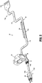
FIG. 2 is a perspective view of a wiring harness of an adapter assembly of the surgical device ofFIG. 1 ; -
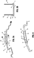
FIG. 3A is a perspective view of a flex cable of the wiring harness ofFIG. 2 , illustrating assembly of a cap, in an open configuration, on a substrate of the flex cable in accordance with an embodiment of the present disclosure; -
FIG. 3B is a cross-sectional view of the flex cable ofFIG. 3A , taken alongline 3B-3B ofFIG. 3A ; -
FIG. 4 is a top view of the flex cable ofFIGS. 3A and 3B , illustrating assembly of electronic components on the substrate of the flex cable; -
FIG. 5A is a perspective view of the flex cable ofFIGS. 3A-4 , illustrating closing of the cap towards a closed configuration; -
FIG. 5B is a cross-sectional view of the flex cable ofFIGS. 3A-5A , illustrating sealing of the cap to the closed configuration; and -
FIG. 6 is a perspective view of a flex cable in accordance with another embodiment of the present disclosure. - Surgical devices in accordance with embodiments of the present disclosure include a printed circuit board having electronic components disposed within a hermetically sealed chamber to protect the electronic components from exposure to moisture during, for example, cleaning and/or sterilizing procedures where the surgical devices may be subjected to high temperatures, steam, chemicals, and/or moisture. The electronic components of the surgical devices of the present disclosure are protected to prevent and/or resist breakdown over multiple/repeated cleaning and sterilizing cycles.
- While the present disclosure is directed to printed circuit boards integrated on a flexible or flex cable of a surgical device, it is envisioned that the principles of the present disclosure are equally applicable to a range of printed circuit boards (e.g., rigid printed circuit boards, such as FR4 circuit boards) and electronic components (e.g., sensors) housed within reusable surgical devices.
- Embodiments of the present disclosure are now described in detail with reference to the drawings in which like reference numerals designate identical or corresponding elements in each of the several views. Throughout this description, the term "proximal" refers to a portion of a device, or component thereof, that is closer to a user, and the term "distal" refers to a portion of the device, or component thereof, that is farther from the user.
- Turning now to
FIG. 1 , a surgical device 1 in accordance with an embodiment of the present disclosure is shown. The surgical device 1 is in the form of a powered handheld electromechanical surgical instrument, and includes apowered handle assembly 10, anadapter assembly 20, and a tool assembly orend effector 30. Thepowered handle assembly 10 is configured for selective connection with theadapter assembly 20 and, in turn, theadapter assembly 20 is configured for selective connection with theend effector 30. - The surgical device 1 will only further be described to the extent necessary to disclose aspects of the present disclosure. For a detailed description of the structure and function of exemplary surgical devices, reference may be made to commonly owned
U.S. Patent Publication Nos. 2016/0296234 , ("the '234 Publication"), and2016/0310134 ("the '134 Publication"), the entire contents of each of which are incorporated herein by reference. - With continued reference to
FIG. 1 , thehandle assembly 10 includes ahandle housing 12 housing a power-pack (not shown) configured to power and control various operations of the surgical device 1, and a plurality of actuators 14 (e.g., finger-actuated control buttons, knobs, toggles, slides, interfaces, and the like) for activating various functions of the surgical device 1. Theadapter assembly 20 includes aproximal portion 20a configured for operable connection to thehandle assembly 10 and adistal portion 20b configured for operable connection to theend effector 30. Theend effector 30 including aloading unit 32 having a plurality of staples (not shown) disposed therein and ananvil assembly 34 including ananvil head 34a and ananvil rod 34b. - For a detailed description of exemplary handle assemblies, adapter assemblies, and end effectors which may be utilized in a surgical device of the present disclosure, reference may be made to the '234 and '134 Publications, the entire contents of each of which were previously incorporated herein by reference.
- With reference now to
FIG. 2 , in conjunction withFIG. 1 , theadapter assembly 20 includes awiring harness 22 having at least oneflex cable 100 electronically interconnecting thehandle assembly 10 and theend effector 30 of the surgical device 1. Thewiring harness 22 of theadapter assembly 20 is configured to enable communication between thehandle assembly 10 and theend effector 30, and to relay power from thehandle assembly 10 to theend effector 30. For example, this communication allows for calibration and communication of data and control signals between theend effector 30 and theadapter assembly 20, as well as between theadapter assembly 20 and thehandle assembly 10, thereby transferring data pertaining to theend effector 30 to thehandle assembly 10 and signals from thehandle assembly 10 to theend effector 30. - The
flex cable 100 includes a body orsubstrate 110 suitable for supporting and/or electrically connectingelectronic components 120 thereto. Thesubstrate 110 is formed from one or more layers or sheets of dielectric material, such as a polymer or a ceramic, and one or more layers of conductive material, such as copper foil, that form conductive traces (not explicitly shown) in thesubstrate 110. - In embodiments, the
substrate 110 of theflex cable 100 is formed from copper-clade polyimides, such as PYRALUX® or NIKAFLEX®, which are registered trademarks owned by DuPont. In some embodiments, thesubstrate 110 is formed from high temperature materials, such as PYRALUX® HT, also a registered trademark owned by DuPont. It should be understood that thesubstrate 110 is configured to allow for the fabrication of single or double sided flex circuits, multilayer flex circuits, and rigid flex circuits. The layers of thesubstrate 110 may be joined to one another by, for example, laminating, welding, and/or using adhesives, among other methods and materials within the purview of those skilled in the art. - A plurality of electrical contact regions 112 (referred to herein as first, second, third, and fourth
electrical contact regions 112a-d) are disposed at terminal ends of the conductive traces (not shown) defined through thesubstrate 110 on afirst side 114 of theflex cable 100. Each of the plurality of electrical contact regions 112 includes one or more pads (e.g., solder pads) to whichelectronic components 120 are joined (e.g., soldered). Theelectronic components 120 may be, for example, surface mount technology and/or through-hole technology, including, for example, integrated circuits (e.g., microchips, microcontrollers, microprocessors), resistors, amplifiers, inductors, capacitors, sensing elements (e.g., optical sensors, pressure sensors, capacitive sensors), buttons, switches, circuit boards, electrical connectors, cables, and/or wires, among other elements or circuitry within the purview of those skilled in the art. - The first
electrical contact regions 112a includes electronic components 120 (see e.g.,FIG. 4 ) disposed thereon. Acap 130 is disposed over the firstelectrical contact region 112a to hermetically seal theelectronic components 120 therein, as described in further detail below. The secondelectrical contact region 112b is in the form of solder pads which are aligned and soldered tosolder pads 24 of anadapter flex cable 26 which, in turn, is electrically coupled to aforce sensor 28 disposed within the adapter assembly 20 (FIG. 1 ) for measuring forces of the end effector 30 (e.g., as shown inFIG. 1 , the pressure applied by theanvil head 34a in the direction of arrow "A" against thedistal portion 20b of theadapter assembly 20, the pressure applied by tissue acting on theanvil head 34a in a direction opposite of arrow "A" as theanvil head 34a is closed onto tissue, etc.). - With continued reference to
FIG. 2 , aproximal portion 110a of thesubstrate 110 includes the thirdelectrical contact region 112c configured for electrical connection with the handle assembly 10 (FIG. 1 ). Adistal portion 110b of thesubstrate 110 includes the fourthelectrical contact region 112d (shown in phantom) coupled to anelectronic component 120 in the form of an electrical connector "C" for electrical connection with the end effector 30 (FIG. 1 ). - It should be understood that while the
flex cable 100 is shown including four electrical contact regions 112, theflex cable 100 may have any number of electrical contact regions depending upon the desired configuration and functionality of theflex cable 100, as is within the purview of those skilled in the art. - Referring now to
FIGS. 3A-5B , a method of integrating and hermetically sealing a printedcircuit board 122 to thesubstrate 110 of theflex cable 100 in accordance with an embodiment of the present disclosure is shown. As shown initially inFIGS. 3A and 3B , acap 130, in an initial open-ended configuration, is joined to thesubstrate 110 of theflex cable 100 such that awall 132 of thecap 130 extends transversely from thefirst side 114 of thesubstrate 110 and defines a closed perimeter around the firstelectrical contact region 112a of thesubstrate 110. Thewall 132 may be sized to be complementary in shape with the firstelectrical contact region 112a of thesubstrate 110. Thewall 132 may be formed from the same material or a different material from that of the substrate 110 (e.g., the same or a different polymeric material). - A
first end portion 132a of thewall 132 includes aflange 134 that provides a flat surface or increased surface area for bonding of thewall 132 to thesubstrate 110. Thefirst end portion 132a of thewall 132 may be secured to thesubstrate 110 by, for example, laminating or welding theflange 134 around an entire perimeter thereof to thesubstrate 110 to seal and form a leak-proof barrier at the junction of thesubstrate 110 and thecap 130. Theflange 134 is positioned adjacent to and is aligned withouter edges 116 of thesubstrate 110, and extends along theouter edges 116 as well as across thesubstrate 110. Asecond end portion 132b of thewall 132 is open to provide access to the firstelectrical contact region 112a of thesubstrate 110. Accordingly, thecap 130 is open-ended during the initial stages of assembling theflex cable 100. - As shown in
FIG. 4 ,electronic components 120 are assembled onto thesubstrate 110 at the firstelectrical contract region 112a disposed within thewall 132 of thecap 130 to form a printedcircuit board 122. Theelectronic components 120 are disposed on thesubstrate 110 in spaced relation relative to thewall 132 of thecap 130 such that theelectronic components 120 are offset a distance from theouter edge 116 of thesubstrate 110 to which theflange 134 of thecap 130 is bonded, as well as the portions of theflange 134 extending across thesubstrate 110. Placement of theelectronic components 120 onto thesubstrate 110 in spaced relation relative to theflange 134 of thecap 130 and/or placement of theelectronic components 120 onto thesubstrate 110 after securing thewall 132 to thesubstrate 110 prevents damage to theelectronic components 120 that may have occurred due to heat transfer during bonding of theflange 134 to thesubstrate 110. - Bonding processes may require high temperatures and/or high pressure which may transfer to the
substrate 110. For example, in embodiments in which thesubstrate 110 and thewall 132 are formed from high temperature materials, high temperatures and/or long bonding times may be required to secure thewall 132 to thesubstrate 110. Accordingly, assembling theelectronic components 120 onto thesubstrate 110 a spaced distance from theflange 134 of thecap 130 either prior to or after securing thewall 132 to thesubstrate 110 minimizes potential damage to theelectronic components 120. Further, assembling theelectronic components 120 onto thesubstrate 110 after securing thewall 132 to thesubstrate 110 mitigates potential damage to theelectronic components 120. - As shown in
FIGS. 5A and 5B , after theelectronic components 120 are assembled onto thesubstrate 110 of theflex cable 100, thecap 130 is sealed to a closed configuration by joining together thesecond end portion 132b of thewall 132. Thesecond end portion 132b of thewall 132 is gathered and secured together in a fluid tight manner to define a hermetically sealedchamber 135 housing theelectronic components 120 therein. As specifically shown inFIG. 5A , for example, thesecond end portion 132b of first andsecond sections wall 132 are moved from an open position (see e.g.,first section 133a) to a closed position (see e.g.,second section 133b) so that, as shown inFIG. 5B , thesecond end portion 132b of the first andsecond sections second end portion 132b of thewall 132 may be secured together by, for example, laminating or welding thesecond end portion 132b of thewall 132 together to seal and form a leak-proof barrier at thesecond end portion 132 of thewall 132. Accordingly, thecap 130 is close-ended at the end stages of assembling theflex cable 100. - The space provided by the
wall 132 around theelectronic components 120 minimizes damage which may occur during the process of closing thesecond end portion 132b of the wall 132 (e.g., by spacing thesecond end portion 132 of thewall 132 a distance from theelectronic components 120 so that heat from the bonding process does not reach the electronic components 120). The height of thewall 132 may vary depending, for example, on the space and/or distance needed to optimize protection of theelectronic components 120 from the settings (e.g., heat) of the bonding process utilized. Thesecond end portion 132b of thewall 132 may be shaped (e.g., have a domed shape) to provide additional space within thecap 130 for theelectronic components 120. - While the
wall 132 is shown as a single piece that is secured to thesubstrate 110 and to itself at thesecond end portion 132b thereof to form the hermetically sealedchamber 135, other configurations of thecap 130 are envisioned. For example, as shown inFIG. 6 , aflex cable 200 includes asubstrate 110, electronic components 120 (see e.g.,FIG. 4 ) assembled onto thesubstrate 110, and acap 230 including awall 232 secured to thesubstrate 110 at afirst end portion 232a thereof around theelectronic components 120, and acover 236 positioned over and secured to asecond end portion 232b of thewall 232 in a fluid tight manner to define a hermetically sealed chamber 235 (shown in phantom) housing the electronic components 120 (see e.g.,FIG. 4 ) therein. Thecover 236 may be secured to thewall 232 by, for example, laminating or welding the entire outer perimeter of thecover 236 to thesecond end portion 232b of thewall 232 to seal and form a leak-proof barrier between thewall 232 and thecover 236. Thecover 236 may be formed from the same material or a different material from that of thewall 232. - Assembly of the
flex cable electronic components 120 are assembled onto thesubstrate 110 and sealed with thecap electronic components 120 in an inert gas environment, such as an inert glove box (e.g., a nitrogen-filled atmosphere), to ensure zero moisture content within theelectronic components 120 and the hermetically sealedchamber - In embodiments, a coating may be disposed over the
electronic components 120 prior to sealing with thecap electronic components 120 against moisture and/or heat. Accordingly, the coating may act as an additional layer of protection from any heat that may be produced while sealing thecap cap substrate 110 and/orelectronic components 120. - In an embodiment, it is further contemplated that a moisture collection agent, e.g., a desiccant, may be provided within the void of the
cap cap U.S. Provisional Patent Application Serial No. 62/464,584, filed on February 28, 2017 - It should be understood that while the flex cable is shown and described above as being disposed within an adapter assembly of the surgical device, the flex cable may be utilized in other components of the surgical device, or other surgical devices. It should also be understood that while the flex cable is described and shown disposed within a powered surgical device, the flex cable may be utilized in non-motor driven yet powered surgical devices (e.g., reusable surgical devices subject to washing and/or sterilization procedures).
- Persons skilled in the art will understand that the structures specifically described herein and shown in the accompanying figures are non-limiting exemplary embodiments, and that the description, disclosure, and figures should be construed merely as exemplary of particular embodiments. It is to be understood, therefore, that the present disclosure is not limited to the precise embodiments described, and that various other changes and modifications may be effected by one skilled in the art without departing from the scope or spirit of the disclosure. For example, the flexible cables of the present disclosure may be utilized in other surgical devices, such as robotic or powered surgical devices/instruments that are subject to sterilization procedures (e.g., autoclaving and/or autowashing). Additionally, the elements and features shown or described in connection with certain embodiments may be combined with the elements and features of certain other embodiments without departing from the scope of the present disclosure, and that such modifications and variations are also included within the scope of the present disclosure. Accordingly, the subject matter of the present disclosure is not limited by what has been particularly shown and described.
- The invention may be described by reference to the following numbered paragraphs:-
- 1. A method of assembling a hermetically sealed printed circuit board, the method comprising:
- securing a first end portion of a wall of a cap to a substrate around an electrical contact region of the substrate, the wall including a second end portion disposed in an open configuration;
- mounting an electronic component to the electrical contact region of the substrate; and
- sealing the second end portion of the wall closed to form a hermetically sealed chamber between the substrate and the cap to encase the electronic component therein.
- 2. The method according to paragraph 1, wherein securing the wall of the cap includes bonding the first end portion of the wall to the substrate.
- 3. The method according to
paragraph 2, wherein the first end portion of the wall includes a flange and bonding the first end portion includes welding the flange to the substrate. - 4. The method according to paragraph 1, wherein the substrate is a flex cable, and mounting the electronic component includes forming a printed circuit board on the flex cable.
- 5. The method according to paragraph 1, wherein sealing the second end portion of the wall includes heat sealing sections of the wall together.
- 6. The method according to paragraph 1, wherein sealing the second end portion of the wall includes securing a cover of the cap to the wall.
- 7. The method according to paragraph 1, wherein mounting the electronic component includes positioning the electronic component on the substrate a spaced distance from outer edges of the substrate, and securing the first end portion of the wall of the cap to the substrate includes bonding the first end portion to the outer edges of the substrate.
- 8. The method according to paragraph 7, wherein mounting the electronic component is subsequent to securing the first end portion of the wall of the cap to the substrate.
- 9. The method according to paragraph 1, further comprising placing the substrate in an inert gas environment prior to mounting the electronic component and sealing the second end portion of the wall.
- 10. The method according to paragraph 1, further comprising applying a coating over the electronic component prior to sealing the second end portion of the wall.
- 11. A method of assembling a flex cable and integrating the flex cable into a surgical device, the method comprising:
- assembling electronic components on a first side of a substrate of a flex cable within a perimeter of a wall secured to the substrate, the wall extending transversely from the first side of the substrate and terminating at an open end; and
- closing the open end of the wall such that the electronic components are disposed within a sealed chamber.
- 12. The method according to paragraph 11, wherein assembling the electronic components includes forming a printed circuit board on the flex cable.
- 13. The method according to paragraph 11, further comprising placing the flex cable in an insert gas environment prior to assembling the electronic components and closing the open end of the wall.
- 14. The method according to paragraph 11, further comprising applying a conformal coating over the electronic components prior to closing the open end of the wall.
- 15. The method according to paragraph 11, further comprising placing the flex cable into an adapter assembly of the surgical device.
- 16. The method according to paragraph 15, further comprising electrically connecting the flex cable to a sensor disposed within the adapter assembly.
- 17. The method according to paragraph 15, further comprising electrically connecting the flex cable with a handle assembly and an end effector of the surgical device to enable communication between the handle assembly, the adapter assembly, and the end effector.
- 18. A hermetic electronics assembly comprising:
- a printed circuit board including a plurality of electronic components disposed on a first side thereof, the plurality of electronic components offset a distance from outer edges of the printed circuit board; and
- a cap including a wall having a first end portion and a second end portion, the first end portion bonded to the printed circuit board entirely around the plurality of electronic components and the second end portion heat sealed closed a distance spaced from the plurality of electronic components,
- wherein the bonding of the first end portion to the printed circuit board and the heat sealing of the second portion of the wall together form a hermetic seal encasing the plurality of electronic components therein.
- 19. The hermetic electronics assembly according to paragraph 18, wherein the first end portion of the cap includes a flange, and the flange is bonded to the outer edges of the printed circuit board.
- 20. The hermetic electronics assembly according to paragraph 18, wherein the printed circuit board is a flex cable.
Claims (15)
- A method of assembling a hermetically sealed printed circuit board, the method comprising:securing a first end portion of a wall of a cap to a substrate around an electrical contact region of the substrate, the wall including a second end portion disposed in an open configuration;mounting an electronic component to the electrical contact region of the substrate; andsealing the second end portion of the wall closed to form a hermetically sealed chamber between the substrate and the cap to encase the electronic component therein.
- The method according to claim 1, wherein securing the wall of the cap includes bonding the first end portion of the wall to the substrate, preferably wherein the first end portion of the wall includes a flange and bonding the first end portion includes welding the flange to the substrate.
- The method according to claim 1 or claim 2, wherein the substrate is a flex cable, and mounting the electronic component includes forming a printed circuit board on the flex cable; and/or wherein sealing the second end portion of the wall includes heat sealing sections of the wall together.
- The method according to any preceding claim, wherein sealing the second end portion of the wall includes securing a cover of the cap to the wall.
- The method according to any preceding claim, wherein mounting the electronic component includes positioning the electronic component on the substrate a spaced distance from outer edges of the substrate, and securing the first end portion of the wall of the cap to the substrate includes bonding the first end portion to the outer edges of the substrate; preferably wherein mounting the electronic component is subsequent to securing the first end portion of the wall of the cap to the substrate.
- The method according to any preceding claim, further comprising placing the substrate in an inert gas environment prior to mounting the electronic component and sealing the second end portion of the wall; and/or further comprising applying a coating over the electronic component prior to sealing the second end portion of the wall.
- A method of assembling a flex cable and integrating the flex cable into a surgical device, the method comprising:assembling electronic components on a first side of a substrate of a flex cable within a perimeter of a wall secured to the substrate, the wall extending transversely from the first side of the substrate and terminating at an open end; andclosing the open end of the wall such that the electronic components are disposed within a sealed chamber.
- The method according to claim 7, wherein assembling the electronic components includes forming a printed circuit board on the flex cable.
- The method according to claim 7 or claim 8, further comprising placing the flex cable in an insert gas environment prior to assembling the electronic components and closing the open end of the wall; and/or further comprising applying a conformal coating over the electronic components prior to closing the open end of the wall.
- The method according to any of claim 7 to 9, further comprising placing the flex cable into an adapter assembly of the surgical device.
- The method according to claim 11, further comprising electrically connecting the flex cable to a sensor disposed within the adapter assembly.
- The method according to claim 10, further comprising electrically connecting the flex cable with a handle assembly and an end effector of the surgical device to enable communication between the handle assembly, the adapter assembly, and the end effector.
- A hermetic electronics assembly comprising:a printed circuit board including a plurality of electronic components disposed on a first side thereof, the plurality of electronic components offset a distance from outer edges of the printed circuit board; anda cap including a wall having a first end portion and a second end portion, the first end portion bonded to the printed circuit board entirely around the plurality of electronic components and the second end portion heat sealed closed a distance spaced from the plurality of electronic components,wherein the bonding of the first end portion to the printed circuit board and the heat sealing of the second portion of the wall together form a hermetic seal encasing the plurality of electronic components therein.
- The hermetic electronics assembly according to claim 13, wherein the first end portion of the cap includes a flange, and the flange is bonded to the outer edges of the printed circuit board.
- The hermetic electronics assembly according to claim 13 or claim 14, wherein the printed circuit board is a flex cable.
Applications Claiming Priority (2)
| Application Number | Priority Date | Filing Date | Title |
|---|---|---|---|
| US201762508101P | 2017-05-18 | 2017-05-18 | |
| US15/947,314 US10588231B2 (en) | 2017-05-18 | 2018-04-06 | Hermetically sealed printed circuit boards |
Publications (2)
| Publication Number | Publication Date |
|---|---|
| EP3403592A1 true EP3403592A1 (en) | 2018-11-21 |
| EP3403592B1 EP3403592B1 (en) | 2020-05-13 |
Family
ID=62235807
Family Applications (1)
| Application Number | Title | Priority Date | Filing Date |
|---|---|---|---|
| EP18173035.9A Active EP3403592B1 (en) | 2017-05-18 | 2018-05-17 | Hermetically sealed printed circuit boards |
Country Status (4)
| Country | Link |
|---|---|
| US (1) | US10588231B2 (en) |
| EP (1) | EP3403592B1 (en) |
| CN (1) | CN108966565B (en) |
| AU (1) | AU2018202601B2 (en) |
Cited By (1)
| Publication number | Priority date | Publication date | Assignee | Title |
|---|---|---|---|---|
| EP3756586A1 (en) * | 2019-06-24 | 2020-12-30 | Covidien LP | Load sensing assemblies and methods of manufacturing load sensing assemblies |
Families Citing this family (306)
| Publication number | Priority date | Publication date | Assignee | Title |
|---|---|---|---|---|
| US9060770B2 (en) | 2003-05-20 | 2015-06-23 | Ethicon Endo-Surgery, Inc. | Robotically-driven surgical instrument with E-beam driver |
| US20070084897A1 (en) | 2003-05-20 | 2007-04-19 | Shelton Frederick E Iv | Articulating surgical stapling instrument incorporating a two-piece e-beam firing mechanism |
| US9072535B2 (en) | 2011-05-27 | 2015-07-07 | Ethicon Endo-Surgery, Inc. | Surgical stapling instruments with rotatable staple deployment arrangements |
| US11890012B2 (en) | 2004-07-28 | 2024-02-06 | Cilag Gmbh International | Staple cartridge comprising cartridge body and attached support |
| US7669746B2 (en) | 2005-08-31 | 2010-03-02 | Ethicon Endo-Surgery, Inc. | Staple cartridges for forming staples having differing formed staple heights |
| US10159482B2 (en) | 2005-08-31 | 2018-12-25 | Ethicon Llc | Fastener cartridge assembly comprising a fixed anvil and different staple heights |
| US11246590B2 (en) | 2005-08-31 | 2022-02-15 | Cilag Gmbh International | Staple cartridge including staple drivers having different unfired heights |
| US11484312B2 (en) | 2005-08-31 | 2022-11-01 | Cilag Gmbh International | Staple cartridge comprising a staple driver arrangement |
| US7934630B2 (en) | 2005-08-31 | 2011-05-03 | Ethicon Endo-Surgery, Inc. | Staple cartridges for forming staples having differing formed staple heights |
| US20070106317A1 (en) | 2005-11-09 | 2007-05-10 | Shelton Frederick E Iv | Hydraulically and electrically actuated articulation joints for surgical instruments |
| US7845537B2 (en) | 2006-01-31 | 2010-12-07 | Ethicon Endo-Surgery, Inc. | Surgical instrument having recording capabilities |
| US11793518B2 (en) | 2006-01-31 | 2023-10-24 | Cilag Gmbh International | Powered surgical instruments with firing system lockout arrangements |
| US11278279B2 (en) | 2006-01-31 | 2022-03-22 | Cilag Gmbh International | Surgical instrument assembly |
| US20120292367A1 (en) | 2006-01-31 | 2012-11-22 | Ethicon Endo-Surgery, Inc. | Robotically-controlled end effector |
| US8186555B2 (en) | 2006-01-31 | 2012-05-29 | Ethicon Endo-Surgery, Inc. | Motor-driven surgical cutting and fastening instrument with mechanical closure system |
| US7753904B2 (en) | 2006-01-31 | 2010-07-13 | Ethicon Endo-Surgery, Inc. | Endoscopic surgical instrument with a handle that can articulate with respect to the shaft |
| US8820603B2 (en) | 2006-01-31 | 2014-09-02 | Ethicon Endo-Surgery, Inc. | Accessing data stored in a memory of a surgical instrument |
| US20110295295A1 (en) | 2006-01-31 | 2011-12-01 | Ethicon Endo-Surgery, Inc. | Robotically-controlled surgical instrument having recording capabilities |
| US8708213B2 (en) | 2006-01-31 | 2014-04-29 | Ethicon Endo-Surgery, Inc. | Surgical instrument having a feedback system |
| US11224427B2 (en) | 2006-01-31 | 2022-01-18 | Cilag Gmbh International | Surgical stapling system including a console and retraction assembly |
| US8992422B2 (en) | 2006-03-23 | 2015-03-31 | Ethicon Endo-Surgery, Inc. | Robotically-controlled endoscopic accessory channel |
| US8322455B2 (en) | 2006-06-27 | 2012-12-04 | Ethicon Endo-Surgery, Inc. | Manually driven surgical cutting and fastening instrument |
| US10568652B2 (en) | 2006-09-29 | 2020-02-25 | Ethicon Llc | Surgical staples having attached drivers of different heights and stapling instruments for deploying the same |
| US11980366B2 (en) | 2006-10-03 | 2024-05-14 | Cilag Gmbh International | Surgical instrument |
| US8684253B2 (en) | 2007-01-10 | 2014-04-01 | Ethicon Endo-Surgery, Inc. | Surgical instrument with wireless communication between a control unit of a robotic system and remote sensor |
| US11291441B2 (en) | 2007-01-10 | 2022-04-05 | Cilag Gmbh International | Surgical instrument with wireless communication between control unit and remote sensor |
| US8840603B2 (en) | 2007-01-10 | 2014-09-23 | Ethicon Endo-Surgery, Inc. | Surgical instrument with wireless communication between control unit and sensor transponders |
| US8827133B2 (en) | 2007-01-11 | 2014-09-09 | Ethicon Endo-Surgery, Inc. | Surgical stapling device having supports for a flexible drive mechanism |
| US7673782B2 (en) | 2007-03-15 | 2010-03-09 | Ethicon Endo-Surgery, Inc. | Surgical stapling instrument having a releasable buttress material |
| US8931682B2 (en) | 2007-06-04 | 2015-01-13 | Ethicon Endo-Surgery, Inc. | Robotically-controlled shaft based rotary drive systems for surgical instruments |
| US11564682B2 (en) | 2007-06-04 | 2023-01-31 | Cilag Gmbh International | Surgical stapler device |
| US7753245B2 (en) | 2007-06-22 | 2010-07-13 | Ethicon Endo-Surgery, Inc. | Surgical stapling instruments |
| US11849941B2 (en) | 2007-06-29 | 2023-12-26 | Cilag Gmbh International | Staple cartridge having staple cavities extending at a transverse angle relative to a longitudinal cartridge axis |
| US11986183B2 (en) | 2008-02-14 | 2024-05-21 | Cilag Gmbh International | Surgical cutting and fastening instrument comprising a plurality of sensors to measure an electrical parameter |
| US8573465B2 (en) | 2008-02-14 | 2013-11-05 | Ethicon Endo-Surgery, Inc. | Robotically-controlled surgical end effector system with rotary actuated closure systems |
| US7866527B2 (en) | 2008-02-14 | 2011-01-11 | Ethicon Endo-Surgery, Inc. | Surgical stapling apparatus with interlockable firing system |
| US9179912B2 (en) | 2008-02-14 | 2015-11-10 | Ethicon Endo-Surgery, Inc. | Robotically-controlled motorized surgical cutting and fastening instrument |
| US8636736B2 (en) | 2008-02-14 | 2014-01-28 | Ethicon Endo-Surgery, Inc. | Motorized surgical cutting and fastening instrument |
| US7819298B2 (en) | 2008-02-14 | 2010-10-26 | Ethicon Endo-Surgery, Inc. | Surgical stapling apparatus with control features operable with one hand |
| BRPI0901282A2 (en) | 2008-02-14 | 2009-11-17 | Ethicon Endo Surgery Inc | surgical cutting and fixation instrument with rf electrodes |
| US20130153641A1 (en) | 2008-02-15 | 2013-06-20 | Ethicon Endo-Surgery, Inc. | Releasable layer of material and surgical end effector having the same |
| US9386983B2 (en) | 2008-09-23 | 2016-07-12 | Ethicon Endo-Surgery, Llc | Robotically-controlled motorized surgical instrument |
| US8210411B2 (en) | 2008-09-23 | 2012-07-03 | Ethicon Endo-Surgery, Inc. | Motor-driven surgical cutting instrument |
| US11648005B2 (en) | 2008-09-23 | 2023-05-16 | Cilag Gmbh International | Robotically-controlled motorized surgical instrument with an end effector |
| US9005230B2 (en) | 2008-09-23 | 2015-04-14 | Ethicon Endo-Surgery, Inc. | Motorized surgical instrument |
| US8608045B2 (en) | 2008-10-10 | 2013-12-17 | Ethicon Endo-Sugery, Inc. | Powered surgical cutting and stapling apparatus with manually retractable firing system |
| US8220688B2 (en) | 2009-12-24 | 2012-07-17 | Ethicon Endo-Surgery, Inc. | Motor-driven surgical cutting instrument with electric actuator directional control assembly |
| US8783543B2 (en) | 2010-07-30 | 2014-07-22 | Ethicon Endo-Surgery, Inc. | Tissue acquisition arrangements and methods for surgical stapling devices |
| US11812965B2 (en) | 2010-09-30 | 2023-11-14 | Cilag Gmbh International | Layer of material for a surgical end effector |
| US8746535B2 (en) | 2010-09-30 | 2014-06-10 | Ethicon Endo-Surgery, Inc. | Tissue thickness compensator comprising detachable portions |
| US10405854B2 (en) | 2010-09-30 | 2019-09-10 | Ethicon Llc | Surgical stapling cartridge with layer retention features |
| US11925354B2 (en) | 2010-09-30 | 2024-03-12 | Cilag Gmbh International | Staple cartridge comprising staples positioned within a compressible portion thereof |
| US9839420B2 (en) | 2010-09-30 | 2017-12-12 | Ethicon Llc | Tissue thickness compensator comprising at least one medicament |
| US10945731B2 (en) | 2010-09-30 | 2021-03-16 | Ethicon Llc | Tissue thickness compensator comprising controlled release and expansion |
| US12213666B2 (en) | 2010-09-30 | 2025-02-04 | Cilag Gmbh International | Tissue thickness compensator comprising layers |
| US9386988B2 (en) | 2010-09-30 | 2016-07-12 | Ethicon End-Surgery, LLC | Retainer assembly including a tissue thickness compensator |
| US11298125B2 (en) | 2010-09-30 | 2022-04-12 | Cilag Gmbh International | Tissue stapler having a thickness compensator |
| US9629814B2 (en) | 2010-09-30 | 2017-04-25 | Ethicon Endo-Surgery, Llc | Tissue thickness compensator configured to redistribute compressive forces |
| US8695866B2 (en) | 2010-10-01 | 2014-04-15 | Ethicon Endo-Surgery, Inc. | Surgical instrument having a power control circuit |
| BR112013027794B1 (en) | 2011-04-29 | 2020-12-15 | Ethicon Endo-Surgery, Inc | CLAMP CARTRIDGE SET |
| US11207064B2 (en) | 2011-05-27 | 2021-12-28 | Cilag Gmbh International | Automated end effector component reloading system for use with a robotic system |
| JP6105041B2 (en) | 2012-03-28 | 2017-03-29 | エシコン・エンド−サージェリィ・インコーポレイテッドEthicon Endo−Surgery,Inc. | Tissue thickness compensator containing capsules defining a low pressure environment |
| RU2014143258A (en) | 2012-03-28 | 2016-05-20 | Этикон Эндо-Серджери, Инк. | FABRIC THICKNESS COMPENSATOR CONTAINING MANY LAYERS |
| US9101358B2 (en) | 2012-06-15 | 2015-08-11 | Ethicon Endo-Surgery, Inc. | Articulatable surgical instrument comprising a firing drive |
| US9289256B2 (en) | 2012-06-28 | 2016-03-22 | Ethicon Endo-Surgery, Llc | Surgical end effectors having angled tissue-contacting surfaces |
| US20140001231A1 (en) | 2012-06-28 | 2014-01-02 | Ethicon Endo-Surgery, Inc. | Firing system lockout arrangements for surgical instruments |
| BR112014032776B1 (en) | 2012-06-28 | 2021-09-08 | Ethicon Endo-Surgery, Inc | SURGICAL INSTRUMENT SYSTEM AND SURGICAL KIT FOR USE WITH A SURGICAL INSTRUMENT SYSTEM |
| US9649111B2 (en) | 2012-06-28 | 2017-05-16 | Ethicon Endo-Surgery, Llc | Replaceable clip cartridge for a clip applier |
| US11278284B2 (en) | 2012-06-28 | 2022-03-22 | Cilag Gmbh International | Rotary drive arrangements for surgical instruments |
| US20140005678A1 (en) | 2012-06-28 | 2014-01-02 | Ethicon Endo-Surgery, Inc. | Rotary drive arrangements for surgical instruments |
| US12383267B2 (en) | 2012-06-28 | 2025-08-12 | Cilag Gmbh International | Robotically powered surgical device with manually-actuatable reversing system |
| US9700310B2 (en) | 2013-08-23 | 2017-07-11 | Ethicon Llc | Firing member retraction devices for powered surgical instruments |
| MX368026B (en) | 2013-03-01 | 2019-09-12 | Ethicon Endo Surgery Inc | Articulatable surgical instruments with conductive pathways for signal communication. |
| MX364729B (en) | 2013-03-01 | 2019-05-06 | Ethicon Endo Surgery Inc | Surgical instrument with a soft stop. |
| US9629629B2 (en) | 2013-03-14 | 2017-04-25 | Ethicon Endo-Surgey, LLC | Control systems for surgical instruments |
| BR112015026109B1 (en) | 2013-04-16 | 2022-02-22 | Ethicon Endo-Surgery, Inc | surgical instrument |
| US9649110B2 (en) | 2013-04-16 | 2017-05-16 | Ethicon Llc | Surgical instrument comprising a closing drive and a firing drive operated from the same rotatable output |
| JP6416260B2 (en) | 2013-08-23 | 2018-10-31 | エシコン エルエルシー | Firing member retractor for a powered surgical instrument |
| US12232723B2 (en) | 2014-03-26 | 2025-02-25 | Cilag Gmbh International | Systems and methods for controlling a segmented circuit |
| US9690362B2 (en) | 2014-03-26 | 2017-06-27 | Ethicon Llc | Surgical instrument control circuit having a safety processor |
| BR112016021943B1 (en) | 2014-03-26 | 2022-06-14 | Ethicon Endo-Surgery, Llc | SURGICAL INSTRUMENT FOR USE BY AN OPERATOR IN A SURGICAL PROCEDURE |
| US9743929B2 (en) | 2014-03-26 | 2017-08-29 | Ethicon Llc | Modular powered surgical instrument with detachable shaft assemblies |
| BR112016023825B1 (en) | 2014-04-16 | 2022-08-02 | Ethicon Endo-Surgery, Llc | STAPLE CARTRIDGE FOR USE WITH A SURGICAL STAPLER AND STAPLE CARTRIDGE FOR USE WITH A SURGICAL INSTRUMENT |
| US10426476B2 (en) | 2014-09-26 | 2019-10-01 | Ethicon Llc | Circular fastener cartridges for applying radially expandable fastener lines |
| BR112016023807B1 (en) | 2014-04-16 | 2022-07-12 | Ethicon Endo-Surgery, Llc | CARTRIDGE SET OF FASTENERS FOR USE WITH A SURGICAL INSTRUMENT |
| US20150297225A1 (en) | 2014-04-16 | 2015-10-22 | Ethicon Endo-Surgery, Inc. | Fastener cartridges including extensions having different configurations |
| JP6636452B2 (en) | 2014-04-16 | 2020-01-29 | エシコン エルエルシーEthicon LLC | Fastener cartridge including extension having different configurations |
| US10111679B2 (en) | 2014-09-05 | 2018-10-30 | Ethicon Llc | Circuitry and sensors for powered medical device |
| BR112017004361B1 (en) | 2014-09-05 | 2023-04-11 | Ethicon Llc | ELECTRONIC SYSTEM FOR A SURGICAL INSTRUMENT |
| US11311294B2 (en) | 2014-09-05 | 2022-04-26 | Cilag Gmbh International | Powered medical device including measurement of closure state of jaws |
| US10105142B2 (en) | 2014-09-18 | 2018-10-23 | Ethicon Llc | Surgical stapler with plurality of cutting elements |
| US11523821B2 (en) | 2014-09-26 | 2022-12-13 | Cilag Gmbh International | Method for creating a flexible staple line |
| US9924944B2 (en) | 2014-10-16 | 2018-03-27 | Ethicon Llc | Staple cartridge comprising an adjunct material |
| US10517594B2 (en) | 2014-10-29 | 2019-12-31 | Ethicon Llc | Cartridge assemblies for surgical staplers |
| US11141153B2 (en) | 2014-10-29 | 2021-10-12 | Cilag Gmbh International | Staple cartridges comprising driver arrangements |
| US9844376B2 (en) | 2014-11-06 | 2017-12-19 | Ethicon Llc | Staple cartridge comprising a releasable adjunct material |
| US10736636B2 (en) | 2014-12-10 | 2020-08-11 | Ethicon Llc | Articulatable surgical instrument system |
| US9987000B2 (en) | 2014-12-18 | 2018-06-05 | Ethicon Llc | Surgical instrument assembly comprising a flexible articulation system |
| US9844374B2 (en) | 2014-12-18 | 2017-12-19 | Ethicon Llc | Surgical instrument systems comprising an articulatable end effector and means for adjusting the firing stroke of a firing member |
| US9844375B2 (en) | 2014-12-18 | 2017-12-19 | Ethicon Llc | Drive arrangements for articulatable surgical instruments |
| US10085748B2 (en) | 2014-12-18 | 2018-10-02 | Ethicon Llc | Locking arrangements for detachable shaft assemblies with articulatable surgical end effectors |
| US9968355B2 (en) | 2014-12-18 | 2018-05-15 | Ethicon Llc | Surgical instruments with articulatable end effectors and improved firing beam support arrangements |
| BR112017012996B1 (en) | 2014-12-18 | 2022-11-08 | Ethicon Llc | SURGICAL INSTRUMENT WITH AN ANvil WHICH IS SELECTIVELY MOVABLE ABOUT AN IMMOVABLE GEOMETRIC AXIS DIFFERENT FROM A STAPLE CARTRIDGE |
| US11154301B2 (en) | 2015-02-27 | 2021-10-26 | Cilag Gmbh International | Modular stapling assembly |
| US10441279B2 (en) | 2015-03-06 | 2019-10-15 | Ethicon Llc | Multiple level thresholds to modify operation of powered surgical instruments |
| US10052044B2 (en) | 2015-03-06 | 2018-08-21 | Ethicon Llc | Time dependent evaluation of sensor data to determine stability, creep, and viscoelastic elements of measures |
| US9808246B2 (en) | 2015-03-06 | 2017-11-07 | Ethicon Endo-Surgery, Llc | Method of operating a powered surgical instrument |
| US9993248B2 (en) | 2015-03-06 | 2018-06-12 | Ethicon Endo-Surgery, Llc | Smart sensors with local signal processing |
| JP2020121162A (en) | 2015-03-06 | 2020-08-13 | エシコン エルエルシーEthicon LLC | Time dependent evaluation of sensor data to determine stability element, creep element and viscoelastic element of measurement |
| US10390825B2 (en) | 2015-03-31 | 2019-08-27 | Ethicon Llc | Surgical instrument with progressive rotary drive systems |
| US10238386B2 (en) | 2015-09-23 | 2019-03-26 | Ethicon Llc | Surgical stapler having motor control based on an electrical parameter related to a motor current |
| US10105139B2 (en) | 2015-09-23 | 2018-10-23 | Ethicon Llc | Surgical stapler having downstream current-based motor control |
| US10299878B2 (en) | 2015-09-25 | 2019-05-28 | Ethicon Llc | Implantable adjunct systems for determining adjunct skew |
| US10736633B2 (en) | 2015-09-30 | 2020-08-11 | Ethicon Llc | Compressible adjunct with looping members |
| US11890015B2 (en) | 2015-09-30 | 2024-02-06 | Cilag Gmbh International | Compressible adjunct with crossing spacer fibers |
| US11690623B2 (en) | 2015-09-30 | 2023-07-04 | Cilag Gmbh International | Method for applying an implantable layer to a fastener cartridge |
| US10265068B2 (en) | 2015-12-30 | 2019-04-23 | Ethicon Llc | Surgical instruments with separable motors and motor control circuits |
| US10292704B2 (en) | 2015-12-30 | 2019-05-21 | Ethicon Llc | Mechanisms for compensating for battery pack failure in powered surgical instruments |
| US11213293B2 (en) | 2016-02-09 | 2022-01-04 | Cilag Gmbh International | Articulatable surgical instruments with single articulation link arrangements |
| BR112018016098B1 (en) | 2016-02-09 | 2023-02-23 | Ethicon Llc | SURGICAL INSTRUMENT |
| US10448948B2 (en) | 2016-02-12 | 2019-10-22 | Ethicon Llc | Mechanisms for compensating for drivetrain failure in powered surgical instruments |
| US11224426B2 (en) | 2016-02-12 | 2022-01-18 | Cilag Gmbh International | Mechanisms for compensating for drivetrain failure in powered surgical instruments |
| US10828028B2 (en) | 2016-04-15 | 2020-11-10 | Ethicon Llc | Surgical instrument with multiple program responses during a firing motion |
| US11607239B2 (en) | 2016-04-15 | 2023-03-21 | Cilag Gmbh International | Systems and methods for controlling a surgical stapling and cutting instrument |
| US10357247B2 (en) | 2016-04-15 | 2019-07-23 | Ethicon Llc | Surgical instrument with multiple program responses during a firing motion |
| US10426467B2 (en) | 2016-04-15 | 2019-10-01 | Ethicon Llc | Surgical instrument with detection sensors |
| US10492783B2 (en) | 2016-04-15 | 2019-12-03 | Ethicon, Llc | Surgical instrument with improved stop/start control during a firing motion |
| US20170296173A1 (en) | 2016-04-18 | 2017-10-19 | Ethicon Endo-Surgery, Llc | Method for operating a surgical instrument |
| US11317917B2 (en) | 2016-04-18 | 2022-05-03 | Cilag Gmbh International | Surgical stapling system comprising a lockable firing assembly |
| US10433840B2 (en) | 2016-04-18 | 2019-10-08 | Ethicon Llc | Surgical instrument comprising a replaceable cartridge jaw |
| US10500000B2 (en) | 2016-08-16 | 2019-12-10 | Ethicon Llc | Surgical tool with manual control of end effector jaws |
| KR101838188B1 (en) * | 2016-10-31 | 2018-03-13 | 비앤알(주) | Circular Stapler |
| US10588630B2 (en) | 2016-12-21 | 2020-03-17 | Ethicon Llc | Surgical tool assemblies with closure stroke reduction features |
| US10918385B2 (en) | 2016-12-21 | 2021-02-16 | Ethicon Llc | Surgical system comprising a firing member rotatable into an articulation state to articulate an end effector of the surgical system |
| US10603036B2 (en) | 2016-12-21 | 2020-03-31 | Ethicon Llc | Articulatable surgical instrument with independent pivotable linkage distal of an articulation lock |
| US20180168625A1 (en) | 2016-12-21 | 2018-06-21 | Ethicon Endo-Surgery, Llc | Surgical stapling instruments with smart staple cartridges |
| JP7010956B2 (en) | 2016-12-21 | 2022-01-26 | エシコン エルエルシー | How to staple tissue |
| US10639035B2 (en) | 2016-12-21 | 2020-05-05 | Ethicon Llc | Surgical stapling instruments and replaceable tool assemblies thereof |
| MX2019007311A (en) | 2016-12-21 | 2019-11-18 | Ethicon Llc | Surgical stapling systems. |
| CN110114014B (en) | 2016-12-21 | 2022-08-09 | 爱惜康有限责任公司 | Surgical instrument system including end effector and firing assembly lockout |
| US20180168615A1 (en) | 2016-12-21 | 2018-06-21 | Ethicon Endo-Surgery, Llc | Method of deforming staples from two different types of staple cartridges with the same surgical stapling instrument |
| JP7010957B2 (en) | 2016-12-21 | 2022-01-26 | エシコン エルエルシー | Shaft assembly with lockout |
| US11419606B2 (en) | 2016-12-21 | 2022-08-23 | Cilag Gmbh International | Shaft assembly comprising a clutch configured to adapt the output of a rotary firing member to two different systems |
| US10675026B2 (en) | 2016-12-21 | 2020-06-09 | Ethicon Llc | Methods of stapling tissue |
| JP6983893B2 (en) | 2016-12-21 | 2021-12-17 | エシコン エルエルシーEthicon LLC | Lockout configuration for surgical end effectors and replaceable tool assemblies |
| CN110114003A (en) | 2016-12-21 | 2019-08-09 | 爱惜康有限责任公司 | Surgical stapling system |
| US10973142B2 (en) | 2017-05-18 | 2021-04-06 | Covidien Lp | Hermetically sealed printed circuit boards |
| US11382638B2 (en) | 2017-06-20 | 2022-07-12 | Cilag Gmbh International | Closed loop feedback control of motor velocity of a surgical stapling and cutting instrument based on measured time over a specified displacement distance |
| US10779820B2 (en) | 2017-06-20 | 2020-09-22 | Ethicon Llc | Systems and methods for controlling motor speed according to user input for a surgical instrument |
| US11517325B2 (en) | 2017-06-20 | 2022-12-06 | Cilag Gmbh International | Closed loop feedback control of motor velocity of a surgical stapling and cutting instrument based on measured displacement distance traveled over a specified time interval |
| US11653914B2 (en) | 2017-06-20 | 2023-05-23 | Cilag Gmbh International | Systems and methods for controlling motor velocity of a surgical stapling and cutting instrument according to articulation angle of end effector |
| US10307170B2 (en) | 2017-06-20 | 2019-06-04 | Ethicon Llc | Method for closed loop control of motor velocity of a surgical stapling and cutting instrument |
| US10881399B2 (en) | 2017-06-20 | 2021-01-05 | Ethicon Llc | Techniques for adaptive control of motor velocity of a surgical stapling and cutting instrument |
| US11324503B2 (en) | 2017-06-27 | 2022-05-10 | Cilag Gmbh International | Surgical firing member arrangements |
| US11266405B2 (en) | 2017-06-27 | 2022-03-08 | Cilag Gmbh International | Surgical anvil manufacturing methods |
| US10993716B2 (en) | 2017-06-27 | 2021-05-04 | Ethicon Llc | Surgical anvil arrangements |
| US10765427B2 (en) | 2017-06-28 | 2020-09-08 | Ethicon Llc | Method for articulating a surgical instrument |
| BR112019027065B1 (en) | 2017-06-28 | 2023-12-26 | Ethicon Llc | SURGICAL INSTRUMENT AND SURGICAL SYSTEM |
| US11564686B2 (en) | 2017-06-28 | 2023-01-31 | Cilag Gmbh International | Surgical shaft assemblies with flexible interfaces |
| EP3420947B1 (en) | 2017-06-28 | 2022-05-25 | Cilag GmbH International | Surgical instrument comprising selectively actuatable rotatable couplers |
| USD906355S1 (en) | 2017-06-28 | 2020-12-29 | Ethicon Llc | Display screen or portion thereof with a graphical user interface for a surgical instrument |
| US20190000459A1 (en) | 2017-06-28 | 2019-01-03 | Ethicon Llc | Surgical instruments with jaws constrained to pivot about an axis upon contact with a closure member that is parked in close proximity to the pivot axis |
| US11484310B2 (en) | 2017-06-28 | 2022-11-01 | Cilag Gmbh International | Surgical instrument comprising a shaft including a closure tube profile |
| US10932772B2 (en) | 2017-06-29 | 2021-03-02 | Ethicon Llc | Methods for closed loop velocity control for robotic surgical instrument |
| US11944300B2 (en) | 2017-08-03 | 2024-04-02 | Cilag Gmbh International | Method for operating a surgical system bailout |
| US11304695B2 (en) | 2017-08-03 | 2022-04-19 | Cilag Gmbh International | Surgical system shaft interconnection |
| US11974742B2 (en) | 2017-08-03 | 2024-05-07 | Cilag Gmbh International | Surgical system comprising an articulation bailout |
| US11471155B2 (en) | 2017-08-03 | 2022-10-18 | Cilag Gmbh International | Surgical system bailout |
| US10743872B2 (en) | 2017-09-29 | 2020-08-18 | Ethicon Llc | System and methods for controlling a display of a surgical instrument |
| US11134944B2 (en) | 2017-10-30 | 2021-10-05 | Cilag Gmbh International | Surgical stapler knife motion controls |
| US10842490B2 (en) | 2017-10-31 | 2020-11-24 | Ethicon Llc | Cartridge body design with force reduction based on firing completion |
| US10779826B2 (en) | 2017-12-15 | 2020-09-22 | Ethicon Llc | Methods of operating surgical end effectors |
| US10835330B2 (en) | 2017-12-19 | 2020-11-17 | Ethicon Llc | Method for determining the position of a rotatable jaw of a surgical instrument attachment assembly |
| US11364027B2 (en) | 2017-12-21 | 2022-06-21 | Cilag Gmbh International | Surgical instrument comprising speed control |
| US12336705B2 (en) | 2017-12-21 | 2025-06-24 | Cilag Gmbh International | Continuous use self-propelled stapling instrument |
| US11311290B2 (en) | 2017-12-21 | 2022-04-26 | Cilag Gmbh International | Surgical instrument comprising an end effector dampener |
| US11324501B2 (en) | 2018-08-20 | 2022-05-10 | Cilag Gmbh International | Surgical stapling devices with improved closure members |
| US20200054321A1 (en) | 2018-08-20 | 2020-02-20 | Ethicon Llc | Surgical instruments with progressive jaw closure arrangements |
| US11291440B2 (en) | 2018-08-20 | 2022-04-05 | Cilag Gmbh International | Method for operating a powered articulatable surgical instrument |
| US11207065B2 (en) | 2018-08-20 | 2021-12-28 | Cilag Gmbh International | Method for fabricating surgical stapler anvils |
| CN111546552A (en) * | 2019-02-08 | 2020-08-18 | 柯惠Lp公司 | Fully encapsulated electronic device and printed circuit board |
| US11696761B2 (en) | 2019-03-25 | 2023-07-11 | Cilag Gmbh International | Firing drive arrangements for surgical systems |
| US11253254B2 (en) | 2019-04-30 | 2022-02-22 | Cilag Gmbh International | Shaft rotation actuator on a surgical instrument |
| US11452528B2 (en) | 2019-04-30 | 2022-09-27 | Cilag Gmbh International | Articulation actuators for a surgical instrument |
| US11426251B2 (en) | 2019-04-30 | 2022-08-30 | Cilag Gmbh International | Articulation directional lights on a surgical instrument |
| US11432816B2 (en) | 2019-04-30 | 2022-09-06 | Cilag Gmbh International | Articulation pin for a surgical instrument |
| US11471157B2 (en) | 2019-04-30 | 2022-10-18 | Cilag Gmbh International | Articulation control mapping for a surgical instrument |
| US11903581B2 (en) | 2019-04-30 | 2024-02-20 | Cilag Gmbh International | Methods for stapling tissue using a surgical instrument |
| US11648009B2 (en) | 2019-04-30 | 2023-05-16 | Cilag Gmbh International | Rotatable jaw tip for a surgical instrument |
| US11660163B2 (en) | 2019-06-28 | 2023-05-30 | Cilag Gmbh International | Surgical system with RFID tags for updating motor assembly parameters |
| US11298127B2 (en) | 2019-06-28 | 2022-04-12 | Cilag GmbH Interational | Surgical stapling system having a lockout mechanism for an incompatible cartridge |
| US11478241B2 (en) | 2019-06-28 | 2022-10-25 | Cilag Gmbh International | Staple cartridge including projections |
| US11684434B2 (en) | 2019-06-28 | 2023-06-27 | Cilag Gmbh International | Surgical RFID assemblies for instrument operational setting control |
| US11399837B2 (en) | 2019-06-28 | 2022-08-02 | Cilag Gmbh International | Mechanisms for motor control adjustments of a motorized surgical instrument |
| US11298132B2 (en) | 2019-06-28 | 2022-04-12 | Cilag GmbH Inlernational | Staple cartridge including a honeycomb extension |
| US12004740B2 (en) | 2019-06-28 | 2024-06-11 | Cilag Gmbh International | Surgical stapling system having an information decryption protocol |
| US20200405307A1 (en) * | 2019-06-28 | 2020-12-31 | Ethicon Llc | Control circuit comprising a coating |
| US11464601B2 (en) | 2019-06-28 | 2022-10-11 | Cilag Gmbh International | Surgical instrument comprising an RFID system for tracking a movable component |
| US11291451B2 (en) | 2019-06-28 | 2022-04-05 | Cilag Gmbh International | Surgical instrument with battery compatibility verification functionality |
| US11771419B2 (en) | 2019-06-28 | 2023-10-03 | Cilag Gmbh International | Packaging for a replaceable component of a surgical stapling system |
| US11523822B2 (en) | 2019-06-28 | 2022-12-13 | Cilag Gmbh International | Battery pack including a circuit interrupter |
| US11553971B2 (en) | 2019-06-28 | 2023-01-17 | Cilag Gmbh International | Surgical RFID assemblies for display and communication |
| US11426167B2 (en) | 2019-06-28 | 2022-08-30 | Cilag Gmbh International | Mechanisms for proper anvil attachment surgical stapling head assembly |
| US11361176B2 (en) | 2019-06-28 | 2022-06-14 | Cilag Gmbh International | Surgical RFID assemblies for compatibility detection |
| US11627959B2 (en) | 2019-06-28 | 2023-04-18 | Cilag Gmbh International | Surgical instruments including manual and powered system lockouts |
| US11259803B2 (en) | 2019-06-28 | 2022-03-01 | Cilag Gmbh International | Surgical stapling system having an information encryption protocol |
| US11350938B2 (en) | 2019-06-28 | 2022-06-07 | Cilag Gmbh International | Surgical instrument comprising an aligned rfid sensor |
| US11638587B2 (en) | 2019-06-28 | 2023-05-02 | Cilag Gmbh International | RFID identification systems for surgical instruments |
| US11853835B2 (en) | 2019-06-28 | 2023-12-26 | Cilag Gmbh International | RFID identification systems for surgical instruments |
| US11246678B2 (en) | 2019-06-28 | 2022-02-15 | Cilag Gmbh International | Surgical stapling system having a frangible RFID tag |
| US11497492B2 (en) | 2019-06-28 | 2022-11-15 | Cilag Gmbh International | Surgical instrument including an articulation lock |
| US11376098B2 (en) | 2019-06-28 | 2022-07-05 | Cilag Gmbh International | Surgical instrument system comprising an RFID system |
| US11224497B2 (en) | 2019-06-28 | 2022-01-18 | Cilag Gmbh International | Surgical systems with multiple RFID tags |
| US20210015512A1 (en) * | 2019-07-16 | 2021-01-21 | Covidien Lp | Sensor encapsulating assembly |
| US11666357B2 (en) * | 2019-09-16 | 2023-06-06 | Covidien Lp | Enclosure for electronics of a surgical instrument |
| US11529139B2 (en) | 2019-12-19 | 2022-12-20 | Cilag Gmbh International | Motor driven surgical instrument |
| US11607219B2 (en) | 2019-12-19 | 2023-03-21 | Cilag Gmbh International | Staple cartridge comprising a detachable tissue cutting knife |
| US12035913B2 (en) | 2019-12-19 | 2024-07-16 | Cilag Gmbh International | Staple cartridge comprising a deployable knife |
| US11304696B2 (en) | 2019-12-19 | 2022-04-19 | Cilag Gmbh International | Surgical instrument comprising a powered articulation system |
| US11911032B2 (en) | 2019-12-19 | 2024-02-27 | Cilag Gmbh International | Staple cartridge comprising a seating cam |
| US11576672B2 (en) | 2019-12-19 | 2023-02-14 | Cilag Gmbh International | Surgical instrument comprising a closure system including a closure member and an opening member driven by a drive screw |
| US11464512B2 (en) | 2019-12-19 | 2022-10-11 | Cilag Gmbh International | Staple cartridge comprising a curved deck surface |
| US11446029B2 (en) | 2019-12-19 | 2022-09-20 | Cilag Gmbh International | Staple cartridge comprising projections extending from a curved deck surface |
| US11529137B2 (en) | 2019-12-19 | 2022-12-20 | Cilag Gmbh International | Staple cartridge comprising driver retention members |
| US11504122B2 (en) | 2019-12-19 | 2022-11-22 | Cilag Gmbh International | Surgical instrument comprising a nested firing member |
| US11559304B2 (en) | 2019-12-19 | 2023-01-24 | Cilag Gmbh International | Surgical instrument comprising a rapid closure mechanism |
| US11234698B2 (en) | 2019-12-19 | 2022-02-01 | Cilag Gmbh International | Stapling system comprising a clamp lockout and a firing lockout |
| US11701111B2 (en) | 2019-12-19 | 2023-07-18 | Cilag Gmbh International | Method for operating a surgical stapling instrument |
| US11931033B2 (en) | 2019-12-19 | 2024-03-19 | Cilag Gmbh International | Staple cartridge comprising a latch lockout |
| US11844520B2 (en) | 2019-12-19 | 2023-12-19 | Cilag Gmbh International | Staple cartridge comprising driver retention members |
| US11291447B2 (en) | 2019-12-19 | 2022-04-05 | Cilag Gmbh International | Stapling instrument comprising independent jaw closing and staple firing systems |
| US12016124B2 (en) * | 2020-04-27 | 2024-06-18 | Covidien Lp | Coating for electrical components of surgical devices |
| USD974560S1 (en) | 2020-06-02 | 2023-01-03 | Cilag Gmbh International | Staple cartridge |
| USD967421S1 (en) | 2020-06-02 | 2022-10-18 | Cilag Gmbh International | Staple cartridge |
| USD975851S1 (en) | 2020-06-02 | 2023-01-17 | Cilag Gmbh International | Staple cartridge |
| USD975850S1 (en) | 2020-06-02 | 2023-01-17 | Cilag Gmbh International | Staple cartridge |
| USD975278S1 (en) | 2020-06-02 | 2023-01-10 | Cilag Gmbh International | Staple cartridge |
| USD976401S1 (en) | 2020-06-02 | 2023-01-24 | Cilag Gmbh International | Staple cartridge |
| USD966512S1 (en) | 2020-06-02 | 2022-10-11 | Cilag Gmbh International | Staple cartridge |
| US12220126B2 (en) | 2020-07-28 | 2025-02-11 | Cilag Gmbh International | Surgical instruments with double pivot articulation joint arrangements |
| US11627966B2 (en) * | 2020-08-26 | 2023-04-18 | Covidien Lp | Surgical stapling device |
| US11896217B2 (en) | 2020-10-29 | 2024-02-13 | Cilag Gmbh International | Surgical instrument comprising an articulation lock |
| US11779330B2 (en) | 2020-10-29 | 2023-10-10 | Cilag Gmbh International | Surgical instrument comprising a jaw alignment system |
| USD1013170S1 (en) | 2020-10-29 | 2024-01-30 | Cilag Gmbh International | Surgical instrument assembly |
| US11844518B2 (en) | 2020-10-29 | 2023-12-19 | Cilag Gmbh International | Method for operating a surgical instrument |
| US11717289B2 (en) | 2020-10-29 | 2023-08-08 | Cilag Gmbh International | Surgical instrument comprising an indicator which indicates that an articulation drive is actuatable |
| US11931025B2 (en) | 2020-10-29 | 2024-03-19 | Cilag Gmbh International | Surgical instrument comprising a releasable closure drive lock |
| USD980425S1 (en) | 2020-10-29 | 2023-03-07 | Cilag Gmbh International | Surgical instrument assembly |
| US11517390B2 (en) | 2020-10-29 | 2022-12-06 | Cilag Gmbh International | Surgical instrument comprising a limited travel switch |
| US11452526B2 (en) | 2020-10-29 | 2022-09-27 | Cilag Gmbh International | Surgical instrument comprising a staged voltage regulation start-up system |
| US11617577B2 (en) | 2020-10-29 | 2023-04-04 | Cilag Gmbh International | Surgical instrument comprising a sensor configured to sense whether an articulation drive of the surgical instrument is actuatable |
| US11534259B2 (en) | 2020-10-29 | 2022-12-27 | Cilag Gmbh International | Surgical instrument comprising an articulation indicator |
| US12053175B2 (en) | 2020-10-29 | 2024-08-06 | Cilag Gmbh International | Surgical instrument comprising a stowed closure actuator stop |
| US11849943B2 (en) | 2020-12-02 | 2023-12-26 | Cilag Gmbh International | Surgical instrument with cartridge release mechanisms |
| US12471982B2 (en) | 2020-12-02 | 2025-11-18 | Cilag Gmbh International | Method for tissue treatment by surgical instrument |
| US11890010B2 (en) | 2020-12-02 | 2024-02-06 | Cllag GmbH International | Dual-sided reinforced reload for surgical instruments |
| US11678882B2 (en) | 2020-12-02 | 2023-06-20 | Cilag Gmbh International | Surgical instruments with interactive features to remedy incidental sled movements |
| US11627960B2 (en) | 2020-12-02 | 2023-04-18 | Cilag Gmbh International | Powered surgical instruments with smart reload with separately attachable exteriorly mounted wiring connections |
| US11653920B2 (en) | 2020-12-02 | 2023-05-23 | Cilag Gmbh International | Powered surgical instruments with communication interfaces through sterile barrier |
| US11653915B2 (en) | 2020-12-02 | 2023-05-23 | Cilag Gmbh International | Surgical instruments with sled location detection and adjustment features |
| US11944296B2 (en) | 2020-12-02 | 2024-04-02 | Cilag Gmbh International | Powered surgical instruments with external connectors |
| US11744581B2 (en) | 2020-12-02 | 2023-09-05 | Cilag Gmbh International | Powered surgical instruments with multi-phase tissue treatment |
| US11737751B2 (en) | 2020-12-02 | 2023-08-29 | Cilag Gmbh International | Devices and methods of managing energy dissipated within sterile barriers of surgical instrument housings |
| US11749877B2 (en) | 2021-02-26 | 2023-09-05 | Cilag Gmbh International | Stapling instrument comprising a signal antenna |
| US11696757B2 (en) | 2021-02-26 | 2023-07-11 | Cilag Gmbh International | Monitoring of internal systems to detect and track cartridge motion status |
| US11950777B2 (en) | 2021-02-26 | 2024-04-09 | Cilag Gmbh International | Staple cartridge comprising an information access control system |
| US11744583B2 (en) | 2021-02-26 | 2023-09-05 | Cilag Gmbh International | Distal communication array to tune frequency of RF systems |
| US11723657B2 (en) | 2021-02-26 | 2023-08-15 | Cilag Gmbh International | Adjustable communication based on available bandwidth and power capacity |
| US11980362B2 (en) | 2021-02-26 | 2024-05-14 | Cilag Gmbh International | Surgical instrument system comprising a power transfer coil |
| US11812964B2 (en) | 2021-02-26 | 2023-11-14 | Cilag Gmbh International | Staple cartridge comprising a power management circuit |
| US11793514B2 (en) | 2021-02-26 | 2023-10-24 | Cilag Gmbh International | Staple cartridge comprising sensor array which may be embedded in cartridge body |
| US11950779B2 (en) | 2021-02-26 | 2024-04-09 | Cilag Gmbh International | Method of powering and communicating with a staple cartridge |
| US11701113B2 (en) | 2021-02-26 | 2023-07-18 | Cilag Gmbh International | Stapling instrument comprising a separate power antenna and a data transfer antenna |
| US11751869B2 (en) | 2021-02-26 | 2023-09-12 | Cilag Gmbh International | Monitoring of multiple sensors over time to detect moving characteristics of tissue |
| US11925349B2 (en) | 2021-02-26 | 2024-03-12 | Cilag Gmbh International | Adjustment to transfer parameters to improve available power |
| US11730473B2 (en) | 2021-02-26 | 2023-08-22 | Cilag Gmbh International | Monitoring of manufacturing life-cycle |
| US12324580B2 (en) | 2021-02-26 | 2025-06-10 | Cilag Gmbh International | Method of powering and communicating with a staple cartridge |
| US12108951B2 (en) | 2021-02-26 | 2024-10-08 | Cilag Gmbh International | Staple cartridge comprising a sensing array and a temperature control system |
| US11826042B2 (en) | 2021-03-22 | 2023-11-28 | Cilag Gmbh International | Surgical instrument comprising a firing drive including a selectable leverage mechanism |
| US11723658B2 (en) | 2021-03-22 | 2023-08-15 | Cilag Gmbh International | Staple cartridge comprising a firing lockout |
| US11717291B2 (en) | 2021-03-22 | 2023-08-08 | Cilag Gmbh International | Staple cartridge comprising staples configured to apply different tissue compression |
| US11806011B2 (en) | 2021-03-22 | 2023-11-07 | Cilag Gmbh International | Stapling instrument comprising tissue compression systems |
| US11737749B2 (en) | 2021-03-22 | 2023-08-29 | Cilag Gmbh International | Surgical stapling instrument comprising a retraction system |
| US11759202B2 (en) | 2021-03-22 | 2023-09-19 | Cilag Gmbh International | Staple cartridge comprising an implantable layer |
| US11826012B2 (en) | 2021-03-22 | 2023-11-28 | Cilag Gmbh International | Stapling instrument comprising a pulsed motor-driven firing rack |
| US11896218B2 (en) | 2021-03-24 | 2024-02-13 | Cilag Gmbh International | Method of using a powered stapling device |
| US11849944B2 (en) | 2021-03-24 | 2023-12-26 | Cilag Gmbh International | Drivers for fastener cartridge assemblies having rotary drive screws |
| US11744603B2 (en) | 2021-03-24 | 2023-09-05 | Cilag Gmbh International | Multi-axis pivot joints for surgical instruments and methods for manufacturing same |
| US12102323B2 (en) | 2021-03-24 | 2024-10-01 | Cilag Gmbh International | Rotary-driven surgical stapling assembly comprising a floatable component |
| US11849945B2 (en) | 2021-03-24 | 2023-12-26 | Cilag Gmbh International | Rotary-driven surgical stapling assembly comprising eccentrically driven firing member |
| US11896219B2 (en) | 2021-03-24 | 2024-02-13 | Cilag Gmbh International | Mating features between drivers and underside of a cartridge deck |
| US11793516B2 (en) | 2021-03-24 | 2023-10-24 | Cilag Gmbh International | Surgical staple cartridge comprising longitudinal support beam |
| US11944336B2 (en) | 2021-03-24 | 2024-04-02 | Cilag Gmbh International | Joint arrangements for multi-planar alignment and support of operational drive shafts in articulatable surgical instruments |
| US11786243B2 (en) | 2021-03-24 | 2023-10-17 | Cilag Gmbh International | Firing members having flexible portions for adapting to a load during a surgical firing stroke |
| US11903582B2 (en) | 2021-03-24 | 2024-02-20 | Cilag Gmbh International | Leveraging surfaces for cartridge installation |
| US11832816B2 (en) | 2021-03-24 | 2023-12-05 | Cilag Gmbh International | Surgical stapling assembly comprising nonplanar staples and planar staples |
| US11857183B2 (en) | 2021-03-24 | 2024-01-02 | Cilag Gmbh International | Stapling assembly components having metal substrates and plastic bodies |
| US11786239B2 (en) | 2021-03-24 | 2023-10-17 | Cilag Gmbh International | Surgical instrument articulation joint arrangements comprising multiple moving linkage features |
| US20220378425A1 (en) | 2021-05-28 | 2022-12-01 | Cilag Gmbh International | Stapling instrument comprising a control system that controls a firing stroke length |
| US12239317B2 (en) | 2021-10-18 | 2025-03-04 | Cilag Gmbh International | Anvil comprising an arrangement of forming pockets proximal to tissue stop |
| US11980363B2 (en) | 2021-10-18 | 2024-05-14 | Cilag Gmbh International | Row-to-row staple array variations |
| US11957337B2 (en) | 2021-10-18 | 2024-04-16 | Cilag Gmbh International | Surgical stapling assembly with offset ramped drive surfaces |
| US11877745B2 (en) | 2021-10-18 | 2024-01-23 | Cilag Gmbh International | Surgical stapling assembly having longitudinally-repeating staple leg clusters |
| US12089841B2 (en) | 2021-10-28 | 2024-09-17 | Cilag CmbH International | Staple cartridge identification systems |
| US11937816B2 (en) | 2021-10-28 | 2024-03-26 | Cilag Gmbh International | Electrical lead arrangements for surgical instruments |
| US12432790B2 (en) | 2021-10-28 | 2025-09-30 | Cilag Gmbh International | Method and device for transmitting UART communications over a security short range wireless communication |
Citations (5)
| Publication number | Priority date | Publication date | Assignee | Title |
|---|---|---|---|---|
| US4372037A (en) * | 1975-03-03 | 1983-02-08 | Hughes Aircraft Company | Large area hybrid microcircuit assembly |
| WO2008066894A2 (en) * | 2006-11-30 | 2008-06-05 | Tessera, Inc. | Substrate for a flexible microelectronic assembly |
| US20130070427A1 (en) * | 2011-07-08 | 2013-03-21 | Great Team Backend Foundry, Inc. | Pre molded can package |
| EP3078335A1 (en) * | 2015-04-10 | 2016-10-12 | Covidien LP | Adapter, extension, and connector assemblies for surgical devices |
| US20160310134A1 (en) | 2015-04-22 | 2016-10-27 | Covidien Lp | Handheld electromechanical surgical system |
Family Cites Families (22)
| Publication number | Priority date | Publication date | Assignee | Title |
|---|---|---|---|---|
| JPS5745955A (en) | 1980-09-02 | 1982-03-16 | Seikosha Co Ltd | Sealing container |
| DE3512628A1 (en) | 1984-04-11 | 1985-10-17 | Moran, Peter, Cork | PACKAGE FOR AN INTEGRATED CIRCUIT |
| DE3913066A1 (en) | 1989-04-21 | 1990-11-08 | Schoppe & Faeser Gmbh | METHOD FOR PRODUCING A HERMETICALLY SEALED HOUSING AND HOUSING PRODUCED BY THIS METHOD |
| US5223741A (en) | 1989-09-01 | 1993-06-29 | Tactical Fabs, Inc. | Package for an integrated circuit structure |
| US5041943A (en) | 1989-11-06 | 1991-08-20 | Allied-Signal Inc. | Hermetically sealed printed circuit board |
| DE4217837B4 (en) | 1991-05-29 | 2006-04-27 | Mitsubishi Denki K.K. | Hermetically sealed housing |
| US5280413A (en) | 1992-09-17 | 1994-01-18 | Ceridian Corporation | Hermetically sealed circuit modules having conductive cap anchors |
| DE19640466B4 (en) | 1996-09-30 | 2006-06-14 | Robert Bosch Gmbh | Metallic support member for electronic components or circuit carrier and method for producing the same |
| JP3982876B2 (en) | 1997-06-30 | 2007-09-26 | 沖電気工業株式会社 | Surface acoustic wave device |
| SE513352C2 (en) | 1998-10-26 | 2000-08-28 | Ericsson Telefon Ab L M | Circuit board and process for making the circuit board |
| TW579555B (en) * | 2000-03-13 | 2004-03-11 | Ibm | Semiconductor chip package and packaging of integrated circuit chip in electronic apparatus |
| US6320128B1 (en) | 2000-05-25 | 2001-11-20 | Visteon Global Technology, Inc. | Environmentally-sealed electronic assembly and method of making same |
| NL1030295C2 (en) | 2005-10-28 | 2007-05-03 | Fei Co | Hermetically sealed housing with electrical lead-through. |
| US8465175B2 (en) * | 2005-11-29 | 2013-06-18 | GE Lighting Solutions, LLC | LED lighting assemblies with thermal overmolding |
| DE102007038331B4 (en) | 2007-08-14 | 2022-02-24 | Vitesco Technologies GmbH | Electronic component and method for manufacturing an electronic component |
| US7898074B2 (en) | 2008-12-12 | 2011-03-01 | Helmut Eckhardt | Electronic devices including flexible electrical circuits and related methods |
| US8666505B2 (en) | 2010-10-26 | 2014-03-04 | Medtronic, Inc. | Wafer-scale package including power source |
| CN202494536U (en) * | 2012-02-17 | 2012-10-17 | 杭州科岛微电子有限公司 | Pressure sensor pressure sensitive element coated with parylene |
| CN203368358U (en) * | 2013-01-17 | 2013-12-25 | 西宁格桑太阳能有限公司 | Plateau-type distributed photovoltaic grid-connected inverter |
| US9442131B2 (en) | 2013-03-13 | 2016-09-13 | Analog Devices, Inc. | System and method for run-time hermeticity detection of a capped MEMS device |
| CN204409587U (en) * | 2015-01-15 | 2015-06-24 | 李辉 | There is the electronic cigarette of transparent windows |
| US20180235544A1 (en) * | 2017-02-17 | 2018-08-23 | General Electric Company | Implantable sensor assembly systems and methods |
-
2018
- 2018-04-06 US US15/947,314 patent/US10588231B2/en active Active
- 2018-04-13 AU AU2018202601A patent/AU2018202601B2/en not_active Ceased
- 2018-05-15 CN CN201810462530.6A patent/CN108966565B/en active Active
- 2018-05-17 EP EP18173035.9A patent/EP3403592B1/en active Active
Patent Citations (6)
| Publication number | Priority date | Publication date | Assignee | Title |
|---|---|---|---|---|
| US4372037A (en) * | 1975-03-03 | 1983-02-08 | Hughes Aircraft Company | Large area hybrid microcircuit assembly |
| WO2008066894A2 (en) * | 2006-11-30 | 2008-06-05 | Tessera, Inc. | Substrate for a flexible microelectronic assembly |
| US20130070427A1 (en) * | 2011-07-08 | 2013-03-21 | Great Team Backend Foundry, Inc. | Pre molded can package |
| EP3078335A1 (en) * | 2015-04-10 | 2016-10-12 | Covidien LP | Adapter, extension, and connector assemblies for surgical devices |
| US20160296234A1 (en) | 2015-04-10 | 2016-10-13 | Covidien Lp | Adapter, extension, and connector assemblies for surgical devices |
| US20160310134A1 (en) | 2015-04-22 | 2016-10-27 | Covidien Lp | Handheld electromechanical surgical system |
Cited By (3)
| Publication number | Priority date | Publication date | Assignee | Title |
|---|---|---|---|---|
| EP3756586A1 (en) * | 2019-06-24 | 2020-12-30 | Covidien LP | Load sensing assemblies and methods of manufacturing load sensing assemblies |
| US11058429B2 (en) | 2019-06-24 | 2021-07-13 | Covidien Lp | Load sensing assemblies and methods of manufacturing load sensing assemblies |
| EP3756586B1 (en) * | 2019-06-24 | 2023-09-27 | Covidien LP | Load sensing assemblies and methods of manufacturing load sensing assemblies |
Also Published As
| Publication number | Publication date |
|---|---|
| US20180338383A1 (en) | 2018-11-22 |
| AU2018202601A1 (en) | 2018-12-06 |
| EP3403592B1 (en) | 2020-05-13 |
| AU2018202601B2 (en) | 2022-10-06 |
| US10588231B2 (en) | 2020-03-10 |
| CN108966565B (en) | 2021-07-27 |
| CN108966565A (en) | 2018-12-07 |
Similar Documents
| Publication | Publication Date | Title |
|---|---|---|
| EP3403592B1 (en) | Hermetically sealed printed circuit boards | |
| US10667408B2 (en) | Fully encapsulated electronics and printed circuit boards | |
| EP3651558A1 (en) | Hermetically sealed printed circuit boards | |
| EP3694298A1 (en) | Fully encapsulated electronics and printed circuit boards | |
| US11304324B2 (en) | Hermetically sealed printed circuit boards | |
| EP3366225A2 (en) | Reusable powered surgical devices having improved durability | |
| US10648875B2 (en) | Force sensor for surgical devices | |
| KR100274279B1 (en) | Method for protecting electronic circuit components and assemblies using a metallized flexible enclosure | |
| US8676321B2 (en) | Connection housing and manufacture of same | |
| EP3766432A1 (en) | Sensor encapsulating assembly | |
| US8437144B2 (en) | Laminate mount assembly | |
| CA3060478A1 (en) | Hermetically sealed printed circuit boards | |
| US20250352213A1 (en) | Surgical devices including sealed electronic components | |
| US11963303B2 (en) | Electronic device for an endoscope, and endoscope | |
| EP3914053A1 (en) | Coating for electrical components of surgical devices | |
| EP4352478B1 (en) | Mechanical compression hermetic force sensors for surgical devices | |
| US12232771B2 (en) | Mechanical compression hermetic force sensors for surgical devices | |
| CN117529640A (en) | Mechanical Compression Seal Force Sensor for Surgical Devices |
Legal Events
| Date | Code | Title | Description |
|---|---|---|---|
| PUAI | Public reference made under article 153(3) epc to a published international application that has entered the european phase |
Free format text: ORIGINAL CODE: 0009012 |
|
| STAA | Information on the status of an ep patent application or granted ep patent |
Free format text: STATUS: THE APPLICATION HAS BEEN PUBLISHED |
|
| AK | Designated contracting states |
Kind code of ref document: A1 Designated state(s): AL AT BE BG CH CY CZ DE DK EE ES FI FR GB GR HR HU IE IS IT LI LT LU LV MC MK MT NL NO PL PT RO RS SE SI SK SM TR |
|
| AX | Request for extension of the european patent |
Extension state: BA ME |
|
| STAA | Information on the status of an ep patent application or granted ep patent |
Free format text: STATUS: REQUEST FOR EXAMINATION WAS MADE |
|
| 17P | Request for examination filed |
Effective date: 20190514 |
|
| RBV | Designated contracting states (corrected) |
Designated state(s): AL AT BE BG CH CY CZ DE DK EE ES FI FR GB GR HR HU IE IS IT LI LT LU LV MC MK MT NL NO PL PT RO RS SE SI SK SM TR |
|
| GRAP | Despatch of communication of intention to grant a patent |
Free format text: ORIGINAL CODE: EPIDOSNIGR1 |
|
| STAA | Information on the status of an ep patent application or granted ep patent |
Free format text: STATUS: GRANT OF PATENT IS INTENDED |
|
| INTG | Intention to grant announced |
Effective date: 20191206 |
|
| RIN1 | Information on inventor provided before grant (corrected) |
Inventor name: VALENTINE, DAVID Inventor name: FIRTH, SCOTT Inventor name: SGROI, ANTHONY |
|
| GRAS | Grant fee paid |
Free format text: ORIGINAL CODE: EPIDOSNIGR3 |
|
| GRAA | (expected) grant |
Free format text: ORIGINAL CODE: 0009210 |
|
| STAA | Information on the status of an ep patent application or granted ep patent |
Free format text: STATUS: THE PATENT HAS BEEN GRANTED |
|
| AK | Designated contracting states |
Kind code of ref document: B1 Designated state(s): AL AT BE BG CH CY CZ DE DK EE ES FI FR GB GR HR HU IE IS IT LI LT LU LV MC MK MT NL NO PL PT RO RS SE SI SK SM TR |
|
| REG | Reference to a national code |
Ref country code: GB Ref legal event code: FG4D |
|
| REG | Reference to a national code |
Ref country code: CH Ref legal event code: EP |
|
| REG | Reference to a national code |
Ref country code: DE Ref legal event code: R096 Ref document number: 602018004393 Country of ref document: DE |
|
| REG | Reference to a national code |
Ref country code: AT Ref legal event code: REF Ref document number: 1269191 Country of ref document: AT Kind code of ref document: T Effective date: 20200615 |
|
| REG | Reference to a national code |
Ref country code: LT Ref legal event code: MG4D |
|
| REG | Reference to a national code |
Ref country code: NL Ref legal event code: MP Effective date: 20200513 |
|
| PG25 | Lapsed in a contracting state [announced via postgrant information from national office to epo] |
Ref country code: IS Free format text: LAPSE BECAUSE OF FAILURE TO SUBMIT A TRANSLATION OF THE DESCRIPTION OR TO PAY THE FEE WITHIN THE PRESCRIBED TIME-LIMIT Effective date: 20200913 Ref country code: PT Free format text: LAPSE BECAUSE OF FAILURE TO SUBMIT A TRANSLATION OF THE DESCRIPTION OR TO PAY THE FEE WITHIN THE PRESCRIBED TIME-LIMIT Effective date: 20200914 Ref country code: NO Free format text: LAPSE BECAUSE OF FAILURE TO SUBMIT A TRANSLATION OF THE DESCRIPTION OR TO PAY THE FEE WITHIN THE PRESCRIBED TIME-LIMIT Effective date: 20200813 Ref country code: GR Free format text: LAPSE BECAUSE OF FAILURE TO SUBMIT A TRANSLATION OF THE DESCRIPTION OR TO PAY THE FEE WITHIN THE PRESCRIBED TIME-LIMIT Effective date: 20200814 Ref country code: FI Free format text: LAPSE BECAUSE OF FAILURE TO SUBMIT A TRANSLATION OF THE DESCRIPTION OR TO PAY THE FEE WITHIN THE PRESCRIBED TIME-LIMIT Effective date: 20200513 Ref country code: SE Free format text: LAPSE BECAUSE OF FAILURE TO SUBMIT A TRANSLATION OF THE DESCRIPTION OR TO PAY THE FEE WITHIN THE PRESCRIBED TIME-LIMIT Effective date: 20200513 Ref country code: LT Free format text: LAPSE BECAUSE OF FAILURE TO SUBMIT A TRANSLATION OF THE DESCRIPTION OR TO PAY THE FEE WITHIN THE PRESCRIBED TIME-LIMIT Effective date: 20200513 |
|
| PG25 | Lapsed in a contracting state [announced via postgrant information from national office to epo] |
Ref country code: BG Free format text: LAPSE BECAUSE OF FAILURE TO SUBMIT A TRANSLATION OF THE DESCRIPTION OR TO PAY THE FEE WITHIN THE PRESCRIBED TIME-LIMIT Effective date: 20200813 Ref country code: RS Free format text: LAPSE BECAUSE OF FAILURE TO SUBMIT A TRANSLATION OF THE DESCRIPTION OR TO PAY THE FEE WITHIN THE PRESCRIBED TIME-LIMIT Effective date: 20200513 Ref country code: LV Free format text: LAPSE BECAUSE OF FAILURE TO SUBMIT A TRANSLATION OF THE DESCRIPTION OR TO PAY THE FEE WITHIN THE PRESCRIBED TIME-LIMIT Effective date: 20200513 Ref country code: HR Free format text: LAPSE BECAUSE OF FAILURE TO SUBMIT A TRANSLATION OF THE DESCRIPTION OR TO PAY THE FEE WITHIN THE PRESCRIBED TIME-LIMIT Effective date: 20200513 |
|
| REG | Reference to a national code |
Ref country code: AT Ref legal event code: MK05 Ref document number: 1269191 Country of ref document: AT Kind code of ref document: T Effective date: 20200513 |
|
| PG25 | Lapsed in a contracting state [announced via postgrant information from national office to epo] |
Ref country code: NL Free format text: LAPSE BECAUSE OF FAILURE TO SUBMIT A TRANSLATION OF THE DESCRIPTION OR TO PAY THE FEE WITHIN THE PRESCRIBED TIME-LIMIT Effective date: 20200513 Ref country code: AL Free format text: LAPSE BECAUSE OF FAILURE TO SUBMIT A TRANSLATION OF THE DESCRIPTION OR TO PAY THE FEE WITHIN THE PRESCRIBED TIME-LIMIT Effective date: 20200513 |
|
| PG25 | Lapsed in a contracting state [announced via postgrant information from national office to epo] |
Ref country code: AT Free format text: LAPSE BECAUSE OF FAILURE TO SUBMIT A TRANSLATION OF THE DESCRIPTION OR TO PAY THE FEE WITHIN THE PRESCRIBED TIME-LIMIT Effective date: 20200513 Ref country code: EE Free format text: LAPSE BECAUSE OF FAILURE TO SUBMIT A TRANSLATION OF THE DESCRIPTION OR TO PAY THE FEE WITHIN THE PRESCRIBED TIME-LIMIT Effective date: 20200513 Ref country code: SM Free format text: LAPSE BECAUSE OF FAILURE TO SUBMIT A TRANSLATION OF THE DESCRIPTION OR TO PAY THE FEE WITHIN THE PRESCRIBED TIME-LIMIT Effective date: 20200513 Ref country code: DK Free format text: LAPSE BECAUSE OF FAILURE TO SUBMIT A TRANSLATION OF THE DESCRIPTION OR TO PAY THE FEE WITHIN THE PRESCRIBED TIME-LIMIT Effective date: 20200513 Ref country code: RO Free format text: LAPSE BECAUSE OF FAILURE TO SUBMIT A TRANSLATION OF THE DESCRIPTION OR TO PAY THE FEE WITHIN THE PRESCRIBED TIME-LIMIT Effective date: 20200513 Ref country code: IT Free format text: LAPSE BECAUSE OF FAILURE TO SUBMIT A TRANSLATION OF THE DESCRIPTION OR TO PAY THE FEE WITHIN THE PRESCRIBED TIME-LIMIT Effective date: 20200513 Ref country code: CZ Free format text: LAPSE BECAUSE OF FAILURE TO SUBMIT A TRANSLATION OF THE DESCRIPTION OR TO PAY THE FEE WITHIN THE PRESCRIBED TIME-LIMIT Effective date: 20200513 Ref country code: ES Free format text: LAPSE BECAUSE OF FAILURE TO SUBMIT A TRANSLATION OF THE DESCRIPTION OR TO PAY THE FEE WITHIN THE PRESCRIBED TIME-LIMIT Effective date: 20200513 |
|
| REG | Reference to a national code |
Ref country code: DE Ref legal event code: R097 Ref document number: 602018004393 Country of ref document: DE |
|
| PG25 | Lapsed in a contracting state [announced via postgrant information from national office to epo] |
Ref country code: MC Free format text: LAPSE BECAUSE OF FAILURE TO SUBMIT A TRANSLATION OF THE DESCRIPTION OR TO PAY THE FEE WITHIN THE PRESCRIBED TIME-LIMIT Effective date: 20200513 Ref country code: PL Free format text: LAPSE BECAUSE OF FAILURE TO SUBMIT A TRANSLATION OF THE DESCRIPTION OR TO PAY THE FEE WITHIN THE PRESCRIBED TIME-LIMIT Effective date: 20200513 Ref country code: SK Free format text: LAPSE BECAUSE OF FAILURE TO SUBMIT A TRANSLATION OF THE DESCRIPTION OR TO PAY THE FEE WITHIN THE PRESCRIBED TIME-LIMIT Effective date: 20200513 |
|
| PLBE | No opposition filed within time limit |
Free format text: ORIGINAL CODE: 0009261 |
|
| REG | Reference to a national code |
Ref country code: BE Ref legal event code: MM Effective date: 20200531 |
|
| STAA | Information on the status of an ep patent application or granted ep patent |
Free format text: STATUS: NO OPPOSITION FILED WITHIN TIME LIMIT |
|
| PG25 | Lapsed in a contracting state [announced via postgrant information from national office to epo] |
Ref country code: LU Free format text: LAPSE BECAUSE OF NON-PAYMENT OF DUE FEES Effective date: 20200517 |
|
| 26N | No opposition filed |
Effective date: 20210216 |
|
| PG25 | Lapsed in a contracting state [announced via postgrant information from national office to epo] |
Ref country code: IE Free format text: LAPSE BECAUSE OF NON-PAYMENT OF DUE FEES Effective date: 20200517 |
|
| PG25 | Lapsed in a contracting state [announced via postgrant information from national office to epo] |
Ref country code: BE Free format text: LAPSE BECAUSE OF NON-PAYMENT OF DUE FEES Effective date: 20200531 Ref country code: SI Free format text: LAPSE BECAUSE OF FAILURE TO SUBMIT A TRANSLATION OF THE DESCRIPTION OR TO PAY THE FEE WITHIN THE PRESCRIBED TIME-LIMIT Effective date: 20200513 |
|
| REG | Reference to a national code |
Ref country code: CH Ref legal event code: PL |
|
| PG25 | Lapsed in a contracting state [announced via postgrant information from national office to epo] |
Ref country code: CH Free format text: LAPSE BECAUSE OF NON-PAYMENT OF DUE FEES Effective date: 20210531 Ref country code: LI Free format text: LAPSE BECAUSE OF NON-PAYMENT OF DUE FEES Effective date: 20210531 |
|
| PG25 | Lapsed in a contracting state [announced via postgrant information from national office to epo] |
Ref country code: TR Free format text: LAPSE BECAUSE OF FAILURE TO SUBMIT A TRANSLATION OF THE DESCRIPTION OR TO PAY THE FEE WITHIN THE PRESCRIBED TIME-LIMIT Effective date: 20200513 Ref country code: MT Free format text: LAPSE BECAUSE OF FAILURE TO SUBMIT A TRANSLATION OF THE DESCRIPTION OR TO PAY THE FEE WITHIN THE PRESCRIBED TIME-LIMIT Effective date: 20200513 Ref country code: CY Free format text: LAPSE BECAUSE OF FAILURE TO SUBMIT A TRANSLATION OF THE DESCRIPTION OR TO PAY THE FEE WITHIN THE PRESCRIBED TIME-LIMIT Effective date: 20200513 |
|
| PG25 | Lapsed in a contracting state [announced via postgrant information from national office to epo] |
Ref country code: MK Free format text: LAPSE BECAUSE OF FAILURE TO SUBMIT A TRANSLATION OF THE DESCRIPTION OR TO PAY THE FEE WITHIN THE PRESCRIBED TIME-LIMIT Effective date: 20200513 |
|
| PGFP | Annual fee paid to national office [announced via postgrant information from national office to epo] |
Ref country code: DE Payment date: 20250423 Year of fee payment: 8 |
|
| PGFP | Annual fee paid to national office [announced via postgrant information from national office to epo] |
Ref country code: FR Payment date: 20250423 Year of fee payment: 8 |
|
| PGFP | Annual fee paid to national office [announced via postgrant information from national office to epo] |
Ref country code: GB Payment date: 20260317 Year of fee payment: 9 |