EP3403487B1 - Method for compacting harvested crops located in a silo - Google Patents
Method for compacting harvested crops located in a silo Download PDFInfo
- Publication number
- EP3403487B1 EP3403487B1 EP18160386.1A EP18160386A EP3403487B1 EP 3403487 B1 EP3403487 B1 EP 3403487B1 EP 18160386 A EP18160386 A EP 18160386A EP 3403487 B1 EP3403487 B1 EP 3403487B1
- Authority
- EP
- European Patent Office
- Prior art keywords
- crop material
- compacting
- silo
- crop
- control device
- Prior art date
- Legal status (The legal status is an assumption and is not a legal conclusion. Google has not performed a legal analysis and makes no representation as to the accuracy of the status listed.)
- Active
Links
- 238000000034 method Methods 0.000 title claims description 51
- 239000000463 material Substances 0.000 claims description 46
- 238000003306 harvesting Methods 0.000 claims description 30
- 238000005315 distribution function Methods 0.000 claims description 12
- 239000002245 particle Substances 0.000 claims description 11
- 230000008901 benefit Effects 0.000 claims description 10
- 238000009826 distribution Methods 0.000 claims description 9
- 230000008569 process Effects 0.000 claims description 7
- XLYOFNOQVPJJNP-UHFFFAOYSA-N water Substances O XLYOFNOQVPJJNP-UHFFFAOYSA-N 0.000 claims description 7
- 230000000694 effects Effects 0.000 claims description 4
- 239000011148 porous material Substances 0.000 claims description 4
- 230000009471 action Effects 0.000 claims description 3
- 238000009434 installation Methods 0.000 claims description 3
- 240000008042 Zea mays Species 0.000 claims description 2
- 235000005824 Zea mays ssp. parviglumis Nutrition 0.000 claims description 2
- 235000002017 Zea mays subsp mays Nutrition 0.000 claims description 2
- 230000006978 adaptation Effects 0.000 claims description 2
- 235000005822 corn Nutrition 0.000 claims description 2
- 230000003340 mental effect Effects 0.000 claims 1
- 238000005056 compaction Methods 0.000 description 108
- 238000007906 compression Methods 0.000 description 14
- 230000006835 compression Effects 0.000 description 13
- 230000032258 transport Effects 0.000 description 8
- 241001057636 Dracaena deremensis Species 0.000 description 3
- 230000001419 dependent effect Effects 0.000 description 3
- 239000004459 forage Substances 0.000 description 3
- 241000196324 Embryophyta Species 0.000 description 2
- 241000208202 Linaceae Species 0.000 description 2
- 235000004431 Linum usitatissimum Nutrition 0.000 description 2
- QVGXLLKOCUKJST-UHFFFAOYSA-N atomic oxygen Chemical compound [O] QVGXLLKOCUKJST-UHFFFAOYSA-N 0.000 description 2
- 230000005540 biological transmission Effects 0.000 description 2
- 230000008859 change Effects 0.000 description 2
- 238000004891 communication Methods 0.000 description 2
- 238000005429 filling process Methods 0.000 description 2
- 229910052760 oxygen Inorganic materials 0.000 description 2
- 239000001301 oxygen Substances 0.000 description 2
- 238000012545 processing Methods 0.000 description 2
- 238000011084 recovery Methods 0.000 description 2
- 230000009467 reduction Effects 0.000 description 2
- 244000025254 Cannabis sativa Species 0.000 description 1
- 239000003570 air Substances 0.000 description 1
- 239000012080 ambient air Substances 0.000 description 1
- 238000013459 approach Methods 0.000 description 1
- 238000002485 combustion reaction Methods 0.000 description 1
- 239000012141 concentrate Substances 0.000 description 1
- 230000003247 decreasing effect Effects 0.000 description 1
- 238000005265 energy consumption Methods 0.000 description 1
- 239000000446 fuel Substances 0.000 description 1
- 230000006872 improvement Effects 0.000 description 1
- 238000011900 installation process Methods 0.000 description 1
- 238000012544 monitoring process Methods 0.000 description 1
- 230000008520 organization Effects 0.000 description 1
- 230000003647 oxidation Effects 0.000 description 1
- 238000007254 oxidation reaction Methods 0.000 description 1
- 230000003252 repetitive effect Effects 0.000 description 1
- 230000009291 secondary effect Effects 0.000 description 1
- 238000004904 shortening Methods 0.000 description 1
- 239000004460 silage Substances 0.000 description 1
- 238000003860 storage Methods 0.000 description 1
- 230000002123 temporal effect Effects 0.000 description 1
- 238000012546 transfer Methods 0.000 description 1
Images

Classifications
-
- A—HUMAN NECESSITIES
- A01—AGRICULTURE; FORESTRY; ANIMAL HUSBANDRY; HUNTING; TRAPPING; FISHING
- A01F—PROCESSING OF HARVESTED PRODUCE; HAY OR STRAW PRESSES; DEVICES FOR STORING AGRICULTURAL OR HORTICULTURAL PRODUCE
- A01F25/00—Storing agricultural or horticultural produce; Hanging-up harvested fruit
- A01F25/16—Arrangements in forage silos
- A01F25/166—Arrangements in forage silos in trench silos
-
- A—HUMAN NECESSITIES
- A01—AGRICULTURE; FORESTRY; ANIMAL HUSBANDRY; HUNTING; TRAPPING; FISHING
- A01B—SOIL WORKING IN AGRICULTURE OR FORESTRY; PARTS, DETAILS, OR ACCESSORIES OF AGRICULTURAL MACHINES OR IMPLEMENTS, IN GENERAL
- A01B69/00—Steering of agricultural machines or implements; Guiding agricultural machines or implements on a desired track
-
- A—HUMAN NECESSITIES
- A01—AGRICULTURE; FORESTRY; ANIMAL HUSBANDRY; HUNTING; TRAPPING; FISHING
- A01F—PROCESSING OF HARVESTED PRODUCE; HAY OR STRAW PRESSES; DEVICES FOR STORING AGRICULTURAL OR HORTICULTURAL PRODUCE
- A01F25/00—Storing agricultural or horticultural produce; Hanging-up harvested fruit
- A01F25/16—Arrangements in forage silos
- A01F25/18—Loading or distributing arrangements
- A01F25/183—Loading arrangements
-
- G—PHYSICS
- G05—CONTROLLING; REGULATING
- G05D—SYSTEMS FOR CONTROLLING OR REGULATING NON-ELECTRIC VARIABLES
- G05D1/00—Control of position, course or altitude of land, water, air, or space vehicles, e.g. automatic pilot
- G05D1/02—Control of position or course in two dimensions
- G05D1/021—Control of position or course in two dimensions specially adapted to land vehicles
- G05D1/0212—Control of position or course in two dimensions specially adapted to land vehicles with means for defining a desired trajectory
- G05D1/0219—Control of position or course in two dimensions specially adapted to land vehicles with means for defining a desired trajectory ensuring the processing of the whole working surface
-
- G—PHYSICS
- G05—CONTROLLING; REGULATING
- G05D—SYSTEMS FOR CONTROLLING OR REGULATING NON-ELECTRIC VARIABLES
- G05D1/00—Control of position, course or altitude of land, water, air, or space vehicles, e.g. automatic pilot
- G05D1/02—Control of position or course in two dimensions
- G05D1/021—Control of position or course in two dimensions specially adapted to land vehicles
- G05D1/0287—Control of position or course in two dimensions specially adapted to land vehicles involving a plurality of land vehicles, e.g. fleet or convoy travelling
- G05D1/0291—Fleet control
- G05D1/0297—Fleet control by controlling means in a control room
Definitions
- the silo may in particular be a so-called flax silo, which is typically used for the storage of crop material. This applies in particular to those cases in which the crop is to be kept for a longer period of time as feed, wherein the crop is compacted in the silo to eliminate air pockets.
- the crop is sealed to the environment typically by means of a cover layer, such as a silo, so that a direct exchange of oxygen between the crop and the environment is prevented. In this way it is prevented that the stored crop rots.
- compaction machines As compaction machines tractors, wheel loaders, rollers or the like are typically used. Of particular importance is a comparatively high weight force that should be exerted by a compaction machine to achieve the desired compaction performance. Furthermore, compaction machines can support a vibration function, which increases the compaction performance noticeably.
- the use of a tractor is insofar preferred as a rule, as such can be readily equipped with a front loader, sliding plate or the like, so that the tractor can also perform a distribution function in addition to a pure compaction function for the crop to be stored. This includes in particular the distribution of delivered to the silo crop on the silo surface.
- the present application is therefore based on the object to provide a method by means of which the filling of a silo is basically optimized.
- the underlying object is achieved, starting from the method of the type described above, according to the invention by the following method step: d) At least within the compression period, the compaction machine moves over the crop autonomously, wherein the compaction machine is controlled by means of at least one control device.
- autonomous operation of a compacting machine is understood in the context of the present application that the compacting machine acts completely independently without the intervention of human intellectual activity. "Autonomous operation” does not necessarily require autonomous operation of the compaction machine completely detached from any external control. In particular, it is not necessary for a workflow of the autonomous compaction machine to be planned and executed exclusively on the basis of data collected by the compaction machine itself by means of its own control device. Instead, the control device can also be supplied with data and specifications from another source and depend on these, which are then only forwarded to the compacting machine and then autonomously converted by the latter.
- a "control device” is understood to mean a device which is suitable for transmitting data to the autonomous compaction machine, in particular for commanding the compaction machine.
- the control device of the compacting machine can specify a driving route and / or transmit further operating data to the compacting machine.
- a data transmission can be made from the compacting machine to the control device, whereby advantageously the compacting machine can give feedback to the control device. This may, for example, relate to the state of the crop to be compacted, as will be explained below separately.
- control device is arranged directly in, on or on the compacting machine or is stationed externally, for example in spatial proximity to the respective silo.
- a communication of an external control device with the autonomous compaction machine can be made in particular via radio.
- the present invention is based on the idea of basically freeing the method for filling a silo from the influence of a human error. Accordingly, the present invention provides a number of advantages, wherein in particular it is ensured that the compaction of the crop within the silo can autonomously follow a given plan.
- This plan is specified by the control device and is executed by the compacting machine in the predetermined manner. This may relate, for example, to a distribution of the compaction power over a silo area and to compliance with the compaction period.
- the efficiency of the method can be increased particularly easily.
- the faster compaction of the crop by means of the compacting machine according to the invention allows an overall shorter residence time of the crop in direct contact with the oxygen of the ambient air.
- the latter should preferably be kept as short as possible in order to improve the oxidation process of the crop avoid.
- the now shortened compression period thus helps to complete the respective silo faster and close by means of a tarpaulin against the environment than is the case in the prior art.
- a further advantage of the method according to the invention is that the basically comparatively repetitive compression process of the crop stored in the silo no longer has to be performed by a specially set-off worker, but can be carried out autonomously or autonomously by the compacting machine. As a result, the efficiency of the process can be further increased.
- the method according to the invention is of particular advantage when the crop is compacted by means of a plurality of compaction machines operating autonomously at the same time.
- the use of a plurality of compaction machines initially leads to a corresponding increase in the compaction power exerted on the crop. This in turn means that a particular desired compression result is achieved in a much shorter time.
- This temporal component is on the one hand under the above-mentioned aspect of the rapid closure of the silo of importance.
- an accelerated compaction of the crop causes a "compaction backlog" on the respective silo to be filled, which can result in a sensitive delay in the harvesting process, being avoided as far as possible.
- This is due to the fact that the work chain of transport vehicles that transport the crop from a harvester, such as a forage harvester, to the silo is disturbed as soon as the crop already delivered to the silo but not further processed does not move into the silo quickly enough is introduced.
- the increase in the compaction performance in the silo helps to bring the delivered crop faster in the silo and consequently as little as possible, preferably not at all, disturb the described working chain of the transport vehicles. In particular, it is at least less frequently necessary, by means of the use of several compaction machines, to deliberately reduce an operating speed of the harvesting vehicle.
- the transmission of movement data from the compacting machines to the control device is particularly advantageous, so that the control device can in particular coordinate travel routes of the compacting machines.
- both conflicts between the driving routes can be minimized, as well as the crossing frequency of all points of the silo can be optimized in such a way that, if possible, all points are crossed at least substantially equally often.
- This procedure corresponds to the most uniform possible distribution of the compaction performance of the compaction machines on the respective crop layer of the silo to be compacted.
- the compaction machines deliberately run over certain places more often than others, if, for example, a good parameter of the crop at certain points require it.
- one of the compaction machines is preferably treated by the control device compared to the other compaction machines.
- This preferred treatment involves the favor of the preferred compaction machine in case of a conflict between operations of different compaction machines. Said preference is implemented by having the preferred compacting machine's operation over the operations of the underage compacting machines.
- the work processes of the disadvantaged Compaction machines are at least temporarily interrupted for the benefit of the preferred compaction machine.
- the preferred compaction machine occupies the position of the so-called "master” within the swarm of all autonomous compaction machines, while the remaining compaction machines are configured as so-called "slaves".
- the master may continue in the event of a conflict between his route with that of a slave unhindered and without interruption, while the slave is at least braked, possibly even completely stopped.
- the control device controls the compaction machine or compaction machines as a function of at least one silo parameter.
- a "silo parameter" can be understood as meaning all parameters which describe either the silo together with the crop located therein or the crop located in the silo as such or the crop delivered to the silo.
- Silo parameters which are of particular importance for the control of the compaction machines can be, for example, the respective current silo height and / or a crop quality parameter of the crop, in particular of the harvested crop that has just been delivered but not yet installed.
- a thickness of an emerging, not yet completely compacted or finished Erntegut für represent a silo.
- control device can change the compaction performance of the compaction machines, for example, depending on the pore volume and / or on the dry mass of the crop and / or the silo height made dependent.
- the compaction performance can be achieved, for example, by changing the compression period.
- the autonomous compaction machine can be equipped, for example, with at least one eccentric. Other options for changing the compaction performance are of course also conceivable.
- a slip in the form of a difference between rotational speeds of a front and a rear axle of a compacting machine actively introduced.
- a change of the footprint of the compacting machine is conceivable, for example by increasing or decreasing a tire pressure of one or more tires of a respective compacting machine.
- At least one, preferably several, good parameters of the crop are advantageously collected directly by means of the compacting machine, the same being equipped with at least one sensor for determining at least one good parameter.
- the compaction machine can transmit the respectively determined good parameter to the control device, so that the latter can take this into account accordingly.
- a survey along with forwarding at least one good parameter continuously takes place, so that current information about the state of the crop is present at any time of the control device.
- the control device has at least one data connection with at least one harvesting vehicle, in particular a forage harvester.
- the harvesting vehicle is the one by which the crop is originally produced.
- the harvesting vehicle may be suitable for harvesting plants and then shredding them so that the crop material ultimately consists of an at least substantially homogenized mass of the shredded plants.
- the former makes it possible to transmit data to the harvesting vehicle as a function of at least one silo parameter.
- control device can deposit at least one piece of information to an operator of the harvesting vehicle in order to obtain this information about the state of the crop and / or the filling process of the silo to inform so that the operator based on this information, his operation and / or an operating parameter of the harvesting vehicle.
- the passing on of the information by the control device can be limited to the simple communication of the respective good parameter or may already include an action recommendation developed as a function of the good parameter.
- the control device informs the machine operator of the harvesting vehicle that the silo is already filled to 70%, from which the machine operator can independently draw the conclusion that the particle size of the crop should henceforth be reduced in order to achieve adequate compaction of the crop to ensure that the upper crop layers of the silo are still outstanding.
- the control device only informs the machine operator, please reduce the particle size of the crop.
- control device acts directly on at least one operating parameter of the harvesting vehicle or changes the same.
- the operator would possibly only be informed that from then on the respective operating parameter concerned was changed automatically, in which a further automation of the method for filling the silo as a whole can be seen.
- the control device acts at least indirectly on an adaptation of the working speed of the harvesting vehicle.
- the control device first effects an extension of the compression period on the basis of a determined good parameter of the crop, and consequently acts as a result of the harvesting vehicle reducing its operating speed.
- the latter should lead to a mass flow of new, additionally introduced into the silo crop is reduced by the harvester produces the crop slower. In this way, a sufficient compaction performance can be ensured in the silo without affecting the working chain of the transport vehicles.
- the inventive method further ausgestaltend meets the at least one autonomous compaction machine in addition to their compaction function also a distribution function by already delivered, but still uncompacted crop autonomously distributed in the silo. This distribution is such that an uncompacted Erntegut Mrs forms.
- the compacting machine upon specifying a layer height to be achieved, applies the uncompacted material to the respective crop layer which is being formed, and then automatically begins to compact it after reaching said layer height.
- the control device predetermines a layer height of compacted crop and the compacting machine continuously introduces and compacts material until the predetermined layer height is reached.
- the compacting machine according to the invention can also accomplish the filling of the silo completely autonomously while also performing a distribution function in addition to the compaction of the crop.
- the layer height of a respective crop layer is controlled as a function of at least one good parameter.
- the layer height in particular the water content of the crop and / or the silo height and / or an average particle size of the crop can be used.
- the latter can be between 5 mm and 40 mm, depending on the intended use of the crop. It is true that the finer the crop, the less it must be compacted.
- the control device can control a working position of the distributing device in a further advantageous embodiment of the method according to the invention, in particular depending on a layer height of the crop layer to be reached.
- the working position may relate to a sliding plate whose working height, with a lower working height leads to a flatter embodiment of the respective Erntegut für and conversely, a higher working height leads to an increase in the layer height.
- the compaction machines assign the crop as a function of at least one Gutparameters autonomous yet to be created or an already emerging crop layer.
- the distribution function of the autonomous compaction machine is not limited to merely distributing crops in the silo, but strategic planning in the silo Expanded on the next to be installed crop.
- the compaction machine preferably performs a layering of the silo in such a way that an installation height of crop material to be installed in the silo is made proportional to the water content and / or antiproportional to the average particle size of the crop and / or antiproportional to the silo height.
- Crop material that is difficult to compact is expediently arranged in a low crop layer within the silo in order to produce an additional compaction performance by means of further crop layers located above the respective crop layer.
- the compaction machine exclusively fulfills a distribution function, while the at least one further compaction machine exclusively fulfills a compaction function.
- exactly two compaction machines are used, exactly one being responsible for the distribution of crop to be fed, while the other one accomplishes the compaction of the crop only. It is understood that the compaction machine performing the distribution function, as part of the distribution of the crop within the silo, passes over crop material already in the silo and thus contributes to compaction thereof to a certain degree. Nevertheless, the task of said compacting machine is solely in the distribution of the crop within the silo.
- those compaction machines that only perform the distribution function are treated at a disadvantage or configured as a slave.
- the other compaction machines are preferably treated or configured as masters. In this way, a rapid compaction of the crop within the silo is ensured.
- a hierarchy between the compaction machines provided for compaction is equally conceivable.
- the inventive method is based on a in the FIGS. 1 to 3 illustrated embodiment illustrated.
- This comprises a silo 1, in which crop 2 is to be stored.
- the crop 2 is distributed by means of two autonomous compaction machines 3, 5 in the silo 1 and compacted there.
- the autonomous compaction machines 3, 5 are controlled by means of a control device 4 , wherein the compaction machines 3, 5 are each connected to the control device 4 by means of a wireless data connection 7 .
- the compacting machines 3, 5 are interconnected by means of a wireless data link 22 .
- the control device 4 is erected in the example shown next to the silo 1 . In the in FIG. 1 As an example, momentarily shown, the compaction machines 3, 5 are moving in the direction of the in FIG. 1 illustrated arrows 20, 21st
- the silo 1 is designed here in the form of a U-shaped flat silo, which is bounded on three of its four edges by means of silo walls 13 .
- the silo 1 is equipped on its underside towards the ground by means of a silo bottom 14 .
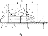
- the structural elements of the silo 1 are particularly well based on the cross section FIG. 3 , There is also a layered structure of the located in the silo 1 crop 2 recognizable. In the state shown, the silo 1 is already almost completely filled.
- the crop is distributed autonomously within the silo 1 by means of a compacting device 12 comprising a compacting machine 3 , wherein the installation of the crop 2 takes place in layers.
- each of the harvest material layer 10 prior to the introduction of a further, overlying that a harvest material layer 10 is produced first by means of the compacting machines 3, 5 is compressed.
- Each of the Erntegut füren 10 finally has a layer height 11 , wherein the sum of all layer tones 11 total results in the silo 6 . It will be appreciated that the latter continually increases during the process until finally the silo 1 is completely filled.
- the distributor 12 of the compacting machine 3 is formed here by a sliding plate.
- the crop layers 10 or their layer heights 11 are controlled as a function of their position within the silo 1 , with crop layers 10 located further down typically having a greater layer height 11 than crop layers 10 lying further up. This is due to the fact that the crop layers 10 located further down in addition to the compaction power which is applied as such by means of the weighting force of the compaction machines 3, 5 (in FIG FIG. 3 by no means closer indicated arrows), are further compressed by means of the weight of the overlying Erntegut Wegen 10 .
- the regulation of the layer height 11 can be carried out particularly easily by means of the distributing device 12 of the compacting machine 3 , it being possible to control a working position of the distributing device 12, in particular by means of the control device 4 .
- this is realized in that the distributor device 12 is mounted rotatably on the compacting machine 3 about an axis of rotation, so that the distributor device 12 is mounted in accordance with an in FIG. 3 shown double arrow 19 can be moved up and down.
- the setting of the working position of the distributor 12 thus corresponds to the setting of a working height thereof in the example shown.
- the compacting machines 3, 5 are configured in the example shown such that a first compacting machine 3, which is equipped with a distributing device 12 , also fulfills a distribution function in addition to a compaction function. This means that the compacting machine 3 autonomously transports the crop 2 delivered at the delivery point 18 into the silo 1 and distributes it there in accordance with a specification of the control device 4 . In this case, the compacting machine 3 typically ensures that the crop 2 is distributed uniformly over the surface of the silo 1 , so that an at least substantially uniform layer height 11 of a harvest crop layer 10 that is in each case formed is formed.
- the other compaction machine 5 does not fulfill a distribution function here, but only and exclusively a compaction function. In the example shown, it is controlled by means of the control device 4 such that it traverses the silo 1 along a travel route 17 , wherein it compresses the crop 2 by virtue of its own weight force.
- An area in which the second compacting machine 5 acts is limited here by way of example to a plateau area 16 of the silo 1 , in which a surface of the crop 2 is at least substantially planar. Subsequently to an open side of the silo 1 towards the plateau region 16 , there is a ramp region 15, in which a height level of the crop 2 drops down to a height level of a terrain upper edge.
- the ramp area 15 is required so that the compaction machines 3, 5 can drive the silo 1 . It forms automatically with increasing height of the silo 6 .
- both compaction machines 3, 5 are each equipped with a sensor not shown in the figures, which allows them to different Good parameters of the crop 2 to capture.
- a restoring behavior of the crop 2 by means of the compacting machines 3, 5 is investigated.
- This restoring behavior which corresponds in principle to a recovery of previously compressed crop 2 , allows a conclusion about the compressibility of the crop 2 .
- the data recorded by means of the sensors are transmitted by means of the data connections 7 to the control device 4 , which creates working sequences of the compacting machines 3, 5 on the basis of these data.
- the latter are in turn communicated to the compaction machines 3, 5 by means of the data connections 7 , whereupon the same continue their autonomous operation accordingly.
- control device 4 changes an estimated compression period as a function of the good parameter "return property" exemplified here in order to sufficiently ensure the compaction of the crop in each case, but at the same time to avoid compaction beyond the required extent.
- driving routes of the compacting machines 3, 5 are adapted to concentrate a compaction power of the same, for example, to a certain area.
- all sorts of further automatically occurring influences of the control device 4 on the operation of the compaction machines 3, 5 are readily conceivable.
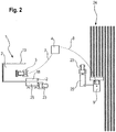
- the control device 4 is furthermore connected to a harvesting vehicle 9 by means of a wireless data connection 8 .
- the harvester 9 is here formed in the form of a forage harvester, which in the example shown is configured to chop corn plants 24 in one go.
- the chopped corn plants 24 then form the crop 2, which is passed directly from the harvester 9 to a trolley 25 , which is then driven by means of a transport vehicle 23 to the silo 1. There, the trolley 25 is emptied at the delivery point 18 .
- control device 4 both with the compaction machines 3, 5, of which in FIG. 2 simplified only the first compaction machine 3 is shown, as well as with the harvester 9 has the particular advantage that silo data of the silo 1 can directly affect the operating parameters of the harvester 9 .
- the control device 4 can transmit information to the harvesting vehicle 9 , from which, for example, an operator of the harvesting vehicle 9 can derive actions for further operation of the harvest. It is also conceivable that the control device 4 acts directly on the data link 8 on at least one operating parameter of the harvester 9 .
- features described above in connection with the exemplary embodiment can in principle also act independently of one another and are not dependent on the feature combination described here.
Description
Die vorliegende Anmeldung betrifft ein Verfahren zur Befüllung eines Silos mit zu lagerndem Erntegut, insbesondere eines Flachsilos mit gehäckseltem Mais, Gras und dergleichen, umfassend die folgenden Verfahrensschritte:
- a) Das zu lagernde Erntegut wird in dem Silo verteilt.
- b) Das in dem Silo befindliche Erntegut wird mittels mindestens einer Verdichtungsmaschine zumindest für die Dauer eines Verdichtungszeitraums fortwährend überfahren, wobei zumindest eine Gewichtskraft der Verdichtungsmaschine auf das Erntegut einwirkt.
- c) Zumindest mittels Wirkung der Gewichtskraft der Verdichtungsmaschine wird das Erntegut verdichtet.
- a) The crop to be stored is distributed in the silo.
- b) The crop located in the silo is continuously run over by means of at least one compaction machine at least for the duration of a compression period, wherein at least one weight of the compacting machine acts on the crop.
- c) At least by the effect of the weight of the compacting machine, the crop is compacted.
Bei dem Silo kann es sich im Sinne der vorliegenden Anmeldung insbesondere um ein sogenanntes Flachsilo handeln, das zur Lagerung von Erntegut typischerweise verwendet wird. Dies betrifft insbesondere solche Fälle, in denen das Erntegut über einen längeren Zeitraum hinweg als Futtermittel vorgehalten werden soll, wobei das Erntegut in dem Silo verdichtet wird, um Lufteinschlüsse zu eliminieren. Nach abgeschlossener Verdichtung bzw. vollständiger Verfüllung des Silos wird das Erntegut zur Umgebung hin typischerweise mittels einer Abdeckschicht, beispielsweise einer Siloplane, abgedichtet, sodass ein unmittelbarer Austausch von Sauerstoff zwischen dem Erntegut und der Umgebung unterbunden ist. Auf diese Weise wird verhindert, dass das gelagerte Erntegut verrottet.In the context of the present application, the silo may in particular be a so-called flax silo, which is typically used for the storage of crop material. This applies in particular to those cases in which the crop is to be kept for a longer period of time as feed, wherein the crop is compacted in the silo to eliminate air pockets. After completion of compaction or complete backfilling of the silo, the crop is sealed to the environment typically by means of a cover layer, such as a silo, so that a direct exchange of oxygen between the crop and the environment is prevented. In this way it is prevented that the stored crop rots.
Als Verdichtungsmaschinen werden typischerweise Traktoren, Radlader, Walzen oder dergleichen verwendet. Von besonderer Bedeutung ist eine vergleichsweise hohe Gewichtskraft, die von einer Verdichtungsmaschine ausgeübt werden sollte, um die gewünschte Verdichtungsleistung zu erzielen. Ferner können Verdichtungsmaschinen unterstützend eine Vibrationsfunktion aufweisen, die die Verdichtungsleistung spürbar erhöht. Die Verwendung eines Traktors wird insoweit in aller Regel bevorzugt, als ein solcher ohne Weiteres mit einem Frontlader, Schiebeschild oder dergleichen ausgestattet werden kann, sodass der Traktor neben einer reinen Verdichtungsfunktion für das zu lagernde Erntegut ferner eine Verteilfunktion erfüllen kann. Diese beinhaltet insbesondere die Verteilung von an dem Silo angeliefertem Erntegut auf der Silofläche.As compaction machines tractors, wheel loaders, rollers or the like are typically used. Of particular importance is a comparatively high weight force that should be exerted by a compaction machine to achieve the desired compaction performance. Furthermore, compaction machines can support a vibration function, which increases the compaction performance noticeably. The use of a tractor is insofar preferred as a rule, as such can be readily equipped with a front loader, sliding plate or the like, so that the tractor can also perform a distribution function in addition to a pure compaction function for the crop to be stored. This includes in particular the distribution of delivered to the silo crop on the silo surface.
Die Befüllung eines Silos mit anschließender Verdichtung des jeweiligen Ernteguts ist im Stand der Technik bereits weitlich bekannt. Ein Verbesserungsbedarf der an sich bewährten Vorgehensweise besteht insofern, als die Organisation des gesamten Befüllungsprozesses im Stand der Technik in aller Regel nicht optimal gestaltet ist. Dies betrifft insbesondere eine Sicherstellung von ausreichend erbrachter Verdichtungsleistung als auch den Einbauprozess des zu verdichtenden Ernteguts in dem Silo. Letzterer ist im Stand der Technik oftmals von fehlerhafter Vorgehensweise geprägt, wobei beispielsweise Erntegut nicht in korrekter Weise und/oder an korrekter Stelle in das Silo eingebracht wird.The filling of a silo with subsequent compaction of the respective crop is already widely known in the art. A need for improvement of the proven procedure is that the organization of the entire filling process in the prior art is generally not optimally designed. This relates in particular to ensuring sufficient compaction performance as well as the installation process of the crop to be compacted in the silo. The latter is often characterized by erroneous procedures in the art, for example, crop is not introduced in the correct way and / or at the correct place in the silo.
Eine Möglichkeit zur besseren Kontrolle des Verdichtungsprozesses offenbart beispielsweise die Europäische Patentanmeldung
Der vorliegenden Anmeldung liegt mithin die Aufgabe zugrunde, ein Verfahren bereitzustellen, mittels dessen die Befüllung eines Silos grundsätzlich optimierbar ist.The present application is therefore based on the object to provide a method by means of which the filling of a silo is basically optimized.
Aus der
Die zugrunde liegende Aufgabe wird ausgehend von dem Verfahren der eingangs beschriebenen Art erfindungsgemäß durch den folgenden Verfahrensschritt gelöst:
d) Zumindest innerhalb des Verdichtungszeitraums überfährt die Verdichtungsmaschine das Erntegut autonom, wobei die Verdichtungsmaschine mittels mindestens einer Steuerungseinrichtung gesteuert wird.The underlying object is achieved, starting from the method of the type described above, according to the invention by the following method step:
d) At least within the compression period, the compaction machine moves over the crop autonomously, wherein the compaction machine is controlled by means of at least one control device.
Unter einem "autonomen Betrieb" einer Verdichtungsmaschine wird im Sinne der vorliegenden Anmeldung verstanden, dass die Verdichtungsmaschine vollständig ohne den Eingriff menschlicher Verstandestätigkeit eigenständig agiert. "Autonomer Betrieb" verlangt nicht notwendigerweise einen eigenständigen Betrieb der Verdichtungsmaschine vollständig losgelöst von jeglicher externen Kontrolle. Insbesondere ist es nicht erforderlich, dass ein Arbeitsablauf der autonomen Verdichtungsmaschine ausschließlich auf Basis von der Verdichtungsmaschine selbst erhobenen Daten mittels einer eigenen Steuerungseinrichtung geplant und ausgeführt wird. Stattdessen kann die Steuerungseinrichtung auch aus anderer Quelle mit Daten und Vorgaben versorgt werden und von diesen abhängen, die sodann lediglich an die Verdichtungsmaschine weitergeleitet und sodann von letzterer autonom umgesetzt werden.Under an "autonomous operation" of a compacting machine is understood in the context of the present application that the compacting machine acts completely independently without the intervention of human intellectual activity. "Autonomous operation" does not necessarily require autonomous operation of the compaction machine completely detached from any external control. In particular, it is not necessary for a workflow of the autonomous compaction machine to be planned and executed exclusively on the basis of data collected by the compaction machine itself by means of its own control device. Instead, the control device can also be supplied with data and specifications from another source and depend on these, which are then only forwarded to the compacting machine and then autonomously converted by the latter.
Unter einer "Steuerungseinrichtung" ist dementsprechend eine Einrichtung zu verstehen, die dazu geeignet ist, Daten an die autonome Verdichtungsmaschine zu übertragen, insbesondere die Verdichtungsmaschine zu befehligen. Beispielsweise kann die Steuerungseinrichtung der Verdichtungsmaschine eine Fahrroute vorgeben und/oder weitere Betriebsdaten an die Verdichtungsmaschine übertragen. Umgekehrt kann eine Datenübertragung ausgehend von der Verdichtungsmaschine zu der Steuerungseinrichtung vorgenommen werden, wodurch vorteilhafterweise die Verdichtungsmaschine eine Rückmeldung an die Steuerungseinrichtung geben kann. Dies kann beispielsweise den Zustand des zu verdichtenden Ernteguts betreffen, wie nachstehend noch gesondert ausgeführt wird.Accordingly, a "control device" is understood to mean a device which is suitable for transmitting data to the autonomous compaction machine, in particular for commanding the compaction machine. For example, the control device of the compacting machine can specify a driving route and / or transmit further operating data to the compacting machine. Conversely, a data transmission can be made from the compacting machine to the control device, whereby advantageously the compacting machine can give feedback to the control device. This may, for example, relate to the state of the crop to be compacted, as will be explained below separately.
Grundsätzlich ist es unerheblich, ob die Steuerungseinrichtung unmittelbar in, an oder auf der Verdichtungsmaschine angeordnet ist oder extern stationiert ist, beispielsweise in räumlicher Nähe zu dem jeweiligen Silo. Eine Kommunikation einer externen Steuerungseinrichtung mit der autonomen Verdichtungsmaschine kann insbesondere über Funk vorgenommen werden.In principle, it is irrelevant whether the control device is arranged directly in, on or on the compacting machine or is stationed externally, for example in spatial proximity to the respective silo. A communication of an external control device with the autonomous compaction machine can be made in particular via radio.
Der vorliegenden Erfindung liegt die Idee zugrunde, das Verfahren zur Befüllung eines Silos grundsätzlich von dem Einfluss eines menschlichen Fehlers zu befreien. Entsprechend bietet die vorliegende Erfindung eine Reihe von Vorteilen, wobei insbesondere sichergestellt ist, dass die Verdichtung des Ernteguts innerhalb des Silos einem vorgegebenen Plan autonom folgen kann. Dieser Plan wird von der Steuerungseinrichtung vorgegeben und wird von der Verdichtungsmaschine in der vorgegebenen Weise ausgeführt. Dies kann beispielsweise eine Verteilung der Verdichtungsleistung über eine Silofläche hinweg sowie die Einhaltung des Verdichtungszeitraums betreffen. Letztlich kann mittels der autonomen Betriebsweise der Verdichtungsmaschine die Effizienz des Verfahrens besonders einfach gesteigert werden.The present invention is based on the idea of basically freeing the method for filling a silo from the influence of a human error. Accordingly, the present invention provides a number of advantages, wherein in particular it is ensured that the compaction of the crop within the silo can autonomously follow a given plan. This plan is specified by the control device and is executed by the compacting machine in the predetermined manner. This may relate, for example, to a distribution of the compaction power over a silo area and to compliance with the compaction period. Ultimately, by means of the autonomous operation of the compacting machine, the efficiency of the method can be increased particularly easily.
Weiterhin ergeben sich Sekundäreffekte, da beispielsweise die Verkürzung des Verdichtungszeitraums für eine jeweils zu verdichtende Erntegutschicht unmittelbar mit der Reduzierung des Energieverbrauchs der Verdichtungsmaschine einhergeht. Sofern letztere beispielsweise mittels eines Verbrennungsmotors angetrieben wird, führt die autonome Betriebsweise der Verdichtungsmaschine indirekt zur Reduktion von Kraftstoffkosten.Secondary effects also result because, for example, the shortening of the compression period for a crop layer to be compacted in each case is directly accompanied by the reduction of the energy consumption of the compacting machine. If the latter is driven for example by means of an internal combustion engine, the autonomous operation of the compacting machine leads indirectly to the reduction of fuel costs.
Weiterhin erlaubt die zügigere Verdichtung des Ernteguts mittels der erfindungsgemäßen Verdichtungsmaschine eine insgesamt kürzere Verweildauer des Ernteguts in unmittelbarem Kontakt mit dem Sauerstoff der Umgebungsluft. Letzterer sollte vorzugsweise möglichst kurz gehalten werden, um Oxidationsprozesses des Ernteguts zu vermeiden. Die nunmehr verkürzte Verdichtungsdauer hilft folglich dabei, das jeweilige Silo zügiger fertigzustellen und mittels einer Abdeckplane gegenüber der Umwelt zu verschließen als dies im Stand der Technik der Fall ist.Furthermore, the faster compaction of the crop by means of the compacting machine according to the invention allows an overall shorter residence time of the crop in direct contact with the oxygen of the ambient air. The latter should preferably be kept as short as possible in order to improve the oxidation process of the crop avoid. The now shortened compression period thus helps to complete the respective silo faster and close by means of a tarpaulin against the environment than is the case in the prior art.
Ein weiterer Vorteil des erfindungsgemäßen Verfahrens besteht darin, dass der im Grunde genommen vergleichsweise repetitive Verdichtungsprozess des in dem Silo eingelagerten Ernteguts nicht länger von einer extra hierfür abgestellten Arbeitskraft vorgenommen werden muss, sondern selbstständig bzw. autonom von der Verdichtungsmaschine ausgeführt werden kann. Hierdurch kann die Wirtschaftlichkeit des Verfahrens weiter gesteigert werden.A further advantage of the method according to the invention is that the basically comparatively repetitive compression process of the crop stored in the silo no longer has to be performed by a specially set-off worker, but can be carried out autonomously or autonomously by the compacting machine. As a result, the efficiency of the process can be further increased.
Das erfindungsgemäße Verfahren ist dann von besonderem Vorteil, wenn das Erntegut mittels einer Mehrzahl gleichzeitig autonom arbeitender Verdichtungsmaschinen verdichtet wird. Die Verwendung einer Mehrzahl von Verdichtungsmaschinen führt zunächst zu einer entsprechenden Steigerung der auf das Erntegut ausgeübten Verdichtungsleistung. Dies führt wiederum dazu, dass ein jeweils gewünschtes Verdichtungsergebnis in deutlich kürzerer Zeit erreicht wird.The method according to the invention is of particular advantage when the crop is compacted by means of a plurality of compaction machines operating autonomously at the same time. The use of a plurality of compaction machines initially leads to a corresponding increase in the compaction power exerted on the crop. This in turn means that a particular desired compression result is achieved in a much shorter time.
Diese zeitliche Komponente ist zum einen unter dem oben genannten Aspekt des zügigen Verschlusses des Silos von Bedeutung. Zum anderen bewirkt eine beschleunigte Verdichtung des Ernteguts, dass ein "Verdichtungsstau" an dem jeweilig zu befüllenden Silo, der eine empfindliche Verzögerung des Ernteprozesses zur Folge haben kann, möglichst vermieden wird. Dies liegt darin begründet, dass die Arbeitskette von Transportfahrzeugen, die das Erntegut von einem Erntefahrzeug, beispielsweise einem Feldhäcksler, zu dem Silo transportieren, gestört wird, sobald das bereits an dem Silo angelieferte, jedoch noch nicht weiter verarbeitete Erntegut nicht zügig genug in das Silo eingebracht wird. Die Erhöhung der Verdichtungsleistung in dem Silo hilft dabei, das angelieferte Erntegut zügiger in das Silo einzubringen und folglich die beschriebene Arbeitskette der Transportfahrzeuge möglichst wenig, vorzugsweise gar nicht, zu stören. Insbesondere ist es mittels der Verwendung mehrerer Verdichtungsmaschinen zumindest weniger häufig notwendig, eine Arbeitsgeschwindigkeit des Erntefahrzeugs bewusst zu reduzieren.This temporal component is on the one hand under the above-mentioned aspect of the rapid closure of the silo of importance. On the other hand, an accelerated compaction of the crop causes a "compaction backlog" on the respective silo to be filled, which can result in a sensitive delay in the harvesting process, being avoided as far as possible. This is due to the fact that the work chain of transport vehicles that transport the crop from a harvester, such as a forage harvester, to the silo is disturbed as soon as the crop already delivered to the silo but not further processed does not move into the silo quickly enough is introduced. The increase in the compaction performance in the silo helps to bring the delivered crop faster in the silo and consequently as little as possible, preferably not at all, disturb the described working chain of the transport vehicles. In particular, it is at least less frequently necessary, by means of the use of several compaction machines, to deliberately reduce an operating speed of the harvesting vehicle.
Von besonderem Vorteil ist die Verwendung von genau zwei autonom betriebenen Verdichtungsmaschinen, die für die Bearbeitung von Silos typischer Größe in aller Regel ausreichen. Die Verwendung von mehr als zwei Verdichtungsmaschinen könnte demgegenüber zu einem deutlich überproportionalen Anstieg von Konflikten zwischen den Verdichtungsmaschinen führen, beispielsweise hinsichtlich deren Fahrrouten.Of particular advantage is the use of exactly two autonomously operated compaction machines, which are usually sufficient for the processing of silos of typical size. In contrast, the use of more than two compaction machines could lead to a significantly disproportionate increase in conflicts between the compaction machines, for example with regard to their driving routes.
Grundsätzlich ist es denkbar, dass bei der Verwendung mehrerer autonomer Verdichtungsmaschinen selbige jeweils mittels einer eigenen Steuerungseinrichtung gesteuert werden. Gleichwohl ist es von besonderem Vorteil, wenn eine einzige zentrale Steuerungseinrichtung die Steuerung sämtlicher autonomer Verdichtungsmaschinen übernimmt. Insbesondere können auf diese Weise Betriebsparameter der Verdichtungsmaschinen mittels der einzigen Steuerungseinrichtung aufeinander abgestimmt werden. Somit ist es bei der Verwendung mehrerer Verdichtungsmaschinen von besonderem Vorteil, wenn diese jeweils Arbeitsdaten an die Steuerungseinrichtung übermitteln, sodass die Steuerungseinrichtung die Arbeitsabläufe der Verdichtungsmaschinen in Abhängigkeit der übermittelten Arbeitsdaten koordinieren kann. Bei diesen Arbeitsdaten kann es sich insbesondere um Sensordaten und/oder Bewegungsdaten der Verdichtungsmaschinen handeln. Die Sensordaten können insbesondere mittels mindestens eines Sensors mindestens einer Verdichtungsmaschine erfasst werden, wobei der Betrieb der Verdichtungsmaschinen von einer Vielzahl verschiedener Parameter abhängig gemacht werden kann. Dies ist nachstehend gesondert erläutert.In principle, it is conceivable that when using a plurality of autonomous compaction machines, the same are each controlled by means of a separate control device. However, it is of particular advantage if a single central control device takes over the control of all autonomous compaction machines. In particular, operating parameters of the compacting machines can be matched to one another in this way by means of the single control device. Thus, when using a plurality of compaction machines, it is of particular advantage if they respectively transmit working data to the control device, so that the control device can coordinate the working sequences of the compaction machines as a function of the transmitted working data. This work data may in particular be sensor data and / or movement data of the compacting machines. The sensor data can be detected in particular by means of at least one sensor of at least one compacting machine, wherein the operation of the compacting machines can be made dependent on a large number of different parameters. This will be explained separately below.
Überdies ist die Übermittlung von Bewegungsdaten von den Verdichtungsmaschinen an die Steuerungseinrichtung besonders vorteilhaft, sodass die Steuerungseinrichtung insbesondere Fahrrouten der Verdichtungsmaschinen koordinieren kann. Auf diese Weise können sowohl Konflikte zwischen den Fahrrouten minimiert, als auch die Überfahrhäufigkeit sämtlicher Stellen des Silos derart optimiert werden, dass nach Möglichkeit sämtliche Stellen zumindest im Wesentlichen gleich oft überfahren werden. Diese Verfahrensweise entspricht einer möglichst gleichmäßigen Verteilung der Verdichtungsleistung der Verdichtungsmaschinen auf die jeweilig zu verdichtende Erntegutschicht des Silos. Ebenso ist es denkbar, dass die Verdichtungsmaschinen bestimmte Stellen bewusst öfter überfahren als andere, falls zum Beispiel ein Gutparameter des Ernteguts an bestimmten Stellen dies verlangen.Moreover, the transmission of movement data from the compacting machines to the control device is particularly advantageous, so that the control device can in particular coordinate travel routes of the compacting machines. In this way, both conflicts between the driving routes can be minimized, as well as the crossing frequency of all points of the silo can be optimized in such a way that, if possible, all points are crossed at least substantially equally often. This procedure corresponds to the most uniform possible distribution of the compaction performance of the compaction machines on the respective crop layer of the silo to be compacted. Likewise, it is conceivable that the compaction machines deliberately run over certain places more often than others, if, for example, a good parameter of the crop at certain points require it.
Bei der Verwendung zweier oder mehrerer autonomer Verdichtungsmaschinen kann es weiterhin vorteilhaft sein, wenn eine der Verdichtungsmaschinen gegenüber den übrigen Verdichtungsmaschinen von der Steuerungseinrichtung bevorzugt behandelt wird. Diese bevorzugte Behandlung beinhaltet die Bevorteilung der bevorzugten Verdichtungsmaschine im Falle eines Konflikts zwischen Arbeitsabläufen verschiedener Verdichtungsmaschinen. Besagte Bevorteilung wird dadurch umgesetzt, dass der Arbeitsablauf der bevorzugten Verdichtungsmaschine Vorrang vor den Arbeitsabläufen der Benachteiligten Verdichtungsmaschinen hat. Insbesondere können die Arbeitsabläufe der Benachteiligten Verdichtungsmaschinen zum Vorteil der bevorzugten Verdichtungsmaschine zumindest zeitweise unterbrochen werden. Mit anderen Worten nimmt die bevorzugte Verdichtungsmaschine innerhalb des Schwarms sämtlicher autonomer Verdichtungsmaschinen die Position des sogenannten "Masters" ein, während die übrigen Verdichtungsmaschinen als sogenannte "Slaves" konfiguriert sind.When two or more autonomous compaction machines are used, it can also be advantageous if one of the compaction machines is preferably treated by the control device compared to the other compaction machines. This preferred treatment involves the favor of the preferred compaction machine in case of a conflict between operations of different compaction machines. Said preference is implemented by having the preferred compacting machine's operation over the operations of the underage compacting machines. In particular, the work processes of the disadvantaged Compaction machines are at least temporarily interrupted for the benefit of the preferred compaction machine. In other words, the preferred compaction machine occupies the position of the so-called "master" within the swarm of all autonomous compaction machines, while the remaining compaction machines are configured as so-called "slaves".
Ein typisches Beispiel für eine derartige Bevorteilung des Masters ist eine Vorfahrtsregelung zu seinen Gunsten, wobei der Master im Falle eines Konflikts zwischen seiner Fahrroute mit derjenigen eines Slaves ungehindert und ohne Unterbrechung weiterfahren darf, während der Slave zumindest gebremst wird, möglicherweise sogar vollständig angehalten wird.A typical example of such a preference of the master is a right of way control in his favor, the master may continue in the event of a conflict between his route with that of a slave unhindered and without interruption, while the slave is at least braked, possibly even completely stopped.
In einer besonders vorteilhaften Ausgestaltung des erfindungsgemäßen Verfahrens sowie unabhängig von der Anzahl der verwendeten autonomen Verdichtungsmaschinen steuert die Steuerungseinrichtung die Verdichtungsmaschine bzw. Verdichtungsmaschinen in Abhängigkeit mindestens eines Siloparameters. Unter einem "Siloparameter" können sämtliche Parameter verstanden werden, die entweder das Silo gemeinsam mit dem darin befindlichen Erntegut oder das in dem Silo befindliche Erntegut als solches oder das an dem Silo angelieferte Erntegut beschreiben. Siloparameter, die für die Steuerung der Verdichtungsmaschinen von besonderer Bedeutung sind, können beispielsweise die jeweils aktuelle Silohöhe und/oder ein Gutparameter des Ernteguts sein, insbesondere des gerade angelieferten, jedoch noch nicht eingebauten Ernteguts. Weiterhin kann eine Dicke einer im Entstehen begriffenen, noch nicht vollständig verdichteten bzw. fertiggestellten Erntegutschicht einen Siloparameter darstellen.In a particularly advantageous embodiment of the method according to the invention and independently of the number of autonomous compaction machines used, the control device controls the compaction machine or compaction machines as a function of at least one silo parameter. A "silo parameter" can be understood as meaning all parameters which describe either the silo together with the crop located therein or the crop located in the silo as such or the crop delivered to the silo. Silo parameters which are of particular importance for the control of the compaction machines can be, for example, the respective current silo height and / or a crop quality parameter of the crop, in particular of the harvested crop that has just been delivered but not yet installed. Furthermore, a thickness of an emerging, not yet completely compacted or finished Erntegutschicht represent a silo.
Dabei wird unter der "Silohöhe" die aktuelle, vom Siloboden aus gemessene Gesamthöhe des bereits in dem Silo angehäuften Ernteguts verstanden. Das bedeutet, dass die Silohöhe in jedem Fall die Höhe der aktuell bearbeiteten Erntegutschicht beschreibt, die in unmittelbaren Kontakt mit der/den Verdichtungsmaschine(n) tritt. Die "Gutparameter" können sämtliche Parameter betreffen, die das Erntegut als solches beschreiben. Hierunter sind insbesondere, jedoch nicht abschließend, die folgenden Parameter zu verstehen:
- ein Rückstellverhalten des Ernteguts;
- eine Dichte des Ernteguts;
- ein Porenvolumen des Ernteguts;
- ein Wassergehalt des Ernteguts;
- ein Trockenmasse des Ernteguts;
- eine durchschnittliche Partikelgröße des Ernteguts.
- a recovery behavior of the crop;
- a density of the crop;
- a pore volume of the crop;
- a water content of the crop;
- a dry matter of the crop;
- an average particle size of the crop.
Insbesondere kann die Steuerungseinrichtung die Verdichtungsleistung der Verdichtungsmaschinen verändern, beispielsweise in Abhängigkeit von dem Porenvolumen und/oder von der Trockenmasse des Ernteguts und/oder der Silohöhe abhängig gemacht werden. Die Verdichtungsleistung kann beispielsweise mittels Veränderung des Verdichtungszeitraums erreicht werden. Ebenso ist es denkbar, zusätzlich zu einer reinen Eigengewichtsverdichtung an der bzw. den Verdichtungsmaschine(n) eine Vibrationsfunktion zu aktivieren, um die Verdichtungsleistung mittels eines dynamischen Verdichtungsanteils zu steigern. Zur Erzeugung einer Vibration kann die autonome Verdichtungsmaschine beispielsweise mit mindestens einem Exzenter ausgestattet sein. Andere Möglichkeiten zur Veränderung der Verdichtungsleistungen sind grundsätzlich selbstverständlich ebenso denkbar. Somit kann beispielsweise ein Schlupf in Form einer Differenz zwischen Drehzahlen einer Vorder- und einer Hinterachse einer Verdichtungsmaschine, aktiv eingebracht werden. Ferner ist eine Veränderung der Aufstandsfläche der Verdichtungsmaschine denkbar, beispielsweise mittels Erhöhung oder Verringerung eines Reifendrucks eines oder mehrerer Reifen einer jeweiligen Verdichtungsmaschine.In particular, the control device can change the compaction performance of the compaction machines, for example, depending on the pore volume and / or on the dry mass of the crop and / or the silo height made dependent. The compaction performance can be achieved, for example, by changing the compression period. Likewise, it is conceivable to activate a vibration function in addition to a pure self-weight compression on the compacting machine (s), in order to increase the compression capacity by means of a dynamic compression ratio. To generate a vibration, the autonomous compaction machine can be equipped, for example, with at least one eccentric. Other options for changing the compaction performance are of course also conceivable. Thus, for example, a slip in the form of a difference between rotational speeds of a front and a rear axle of a compacting machine, actively introduced. Furthermore, a change of the footprint of the compacting machine is conceivable, for example by increasing or decreasing a tire pressure of one or more tires of a respective compacting machine.
Mindestens ein, vorzugsweise mehrere, Gutparameter des Ernteguts werden vorteilhafterweise unmittelbar mittels der Verdichtungsmaschine erhoben, wobei selbige mit mindestens einem Sensor zur Ermittlung mindestens eines Gutparameters ausgestattet ist. Die Verdichtungsmaschine kann den jeweils ermittelten Gutparameter an die Steuerungseinrichtung übertragen, sodass letztere diesen entsprechend berücksichtigen kann. Vorteilhafterweise findet eine Erhebung mitsamt Weiterleitung mindestens eines Gutparameters fortwährend statt, sodass zu jeder Zeit der Steuerungseinrichtung aktuelle Informationen über den Zustand des Ernteguts vorliegen.At least one, preferably several, good parameters of the crop are advantageously collected directly by means of the compacting machine, the same being equipped with at least one sensor for determining at least one good parameter. The compaction machine can transmit the respectively determined good parameter to the control device, so that the latter can take this into account accordingly. Advantageously, a survey along with forwarding at least one good parameter continuously takes place, so that current information about the state of the crop is present at any time of the control device.
In einer besonders vorteilhaften Ausgestaltung des erfindungsgemäßen Verfahrens weist die Steuerungseinrichtung mindestens eine Datenverbindung mit mindestens einem Erntefahrzeug, insbesondere einen Feldhäcksler, auf. Bei dem Erntefahrzeug handelt es sich um dasjenige Fahrzeug, mittels dessen das Erntegut ursprünglich produziert wird. Insbesondere kann das Erntefahrzeug dazu geeignet sein, Pflanzen zu ernten und sodann zu zerkleinern, sodass das Erntegut letztlich aus einer zumindest im Wesentlichen homogenisierten Masse der zerkleinerten Pflanzen besteht. Mittels der Datenverbindung zwischen der Steuerungseinrichtung und dem Erntefahrzeug ist es ersterer ermöglicht, in Abhängigkeit mindestens eines Siloparameters Daten an das Erntefahrzeug zu übermitteln. Insbesondere kann die Steuerungseinrichtung zumindest eine Information an einen Maschinenführer des Erntefahrzeugs absetzen, um diesen über den Zustand des Ernteguts und/oder des Befüllungsprozesses des Silos zu informieren, sodass der Maschinenführer auf Basis dieser Information seine Arbeitsweise und/oder einen Betriebsparameter des Erntefahrzeugs anpassen kann.In a particularly advantageous embodiment of the method according to the invention, the control device has at least one data connection with at least one harvesting vehicle, in particular a forage harvester. The harvesting vehicle is the one by which the crop is originally produced. In particular, the harvesting vehicle may be suitable for harvesting plants and then shredding them so that the crop material ultimately consists of an at least substantially homogenized mass of the shredded plants. By means of the data connection between the control device and the harvesting vehicle, the former makes it possible to transmit data to the harvesting vehicle as a function of at least one silo parameter. In particular, the control device can deposit at least one piece of information to an operator of the harvesting vehicle in order to obtain this information about the state of the crop and / or the filling process of the silo to inform so that the operator based on this information, his operation and / or an operating parameter of the harvesting vehicle.
Die Weitergabe der Information seitens der Steuerungseinrichtung kann dabei auf die schlichte Mitteilung des jeweiligen Gutparameters beschränkt sein oder bereits eine in Abhängigkeit des Gutparameters erarbeitete Handlungsempfehlung beinhalten. Somit ist es beispielsweise denkbar, dass die Steuerungseinrichtung den Maschinenführer des Erntefahrzeugs darüber informiert, dass das Silo bereits zu 70 % gefüllt ist, woraus der Maschinenführer eigenständig den Rückschluss ziehen kann, dass die Partikelgröße des Ernteguts fortan reduziert werden sollte, um eine hinreichende Verdichtung der noch ausstehenden oberen Erntegutschichten des Silos sicherstellen zu können. Alternativ ist es denkbar, dass die Steuerungseinrichtung dem Maschinenführer lediglich mitteilt, bitte die Partikelgröße des Ernteguts zu reduzieren.The passing on of the information by the control device can be limited to the simple communication of the respective good parameter or may already include an action recommendation developed as a function of the good parameter. Thus, it is conceivable, for example, that the control device informs the machine operator of the harvesting vehicle that the silo is already filled to 70%, from which the machine operator can independently draw the conclusion that the particle size of the crop should henceforth be reduced in order to achieve adequate compaction of the crop to ensure that the upper crop layers of the silo are still outstanding. Alternatively, it is conceivable that the control device only informs the machine operator, please reduce the particle size of the crop.
Noch darüber hinaus besteht die Möglichkeit, dass die Steuerungseinrichtung unmittelbar auf mindestens einen Betriebsparameter des Erntefahrzeugs einwirkt bzw. selbigen verändert. In diesem Fall würde der Maschinenführer womöglich lediglich informiert werden, dass fortan der jeweils betroffene Betriebsparameter automatisch verändert wurde, worin eine weitere Automatisierung des Verfahrens zur Befüllung des Silos insgesamt zu sehen ist.Moreover, there is the possibility that the control device acts directly on at least one operating parameter of the harvesting vehicle or changes the same. In this case, the operator would possibly only be informed that from then on the respective operating parameter concerned was changed automatically, in which a further automation of the method for filling the silo as a whole can be seen.
Soweit eine Datenübertragung von der Steuerungseinrichtung auf das Erntefahrzeug vorgenommen wird, ist es besonders vorteilhaft, wenn die Steuerungseinrichtung in Abhängigkeit von einer Länge des Verdichtungszeitraums zumindest mittelbar auf eine Anpassung der Arbeitsgeschwindigkeit des Erntefahrzeugs hinwirkt. Somit ist es beispielsweise denkbar, dass in einer logischen Abfolge zunächst aufgrund eines ermittelten Gutparameters des Ernteguts die Steuerungseinrichtung eine Verlängerung des Verdichtungszeitraums bewirkt und infolgedessen daraufhin wirkt, dass das Erntefahrzeug seine Arbeitsgeschwindigkeit verringert. Letzteres soll dazu führen, dass ein Massenstrom von neuem, zusätzlich in das Silo einzubringen Ernteguts verringert wird, indem das Erntefahrzeug das Erntegut langsamer produziert. Auf diese Weise kann ohne Beeinträchtigung der Arbeitskette der Transportfahrzeuge eine hinreichende Verdichtungsleistung in dem Silo sichergestellt werden.As far as a data transfer from the control device to the harvesting vehicle is carried out, it is particularly advantageous if the control device, depending on a length of the compression period, acts at least indirectly on an adaptation of the working speed of the harvesting vehicle. Thus, it is conceivable, for example, that, in a logical sequence, the control device first effects an extension of the compression period on the basis of a determined good parameter of the crop, and consequently acts as a result of the harvesting vehicle reducing its operating speed. The latter should lead to a mass flow of new, additionally introduced into the silo crop is reduced by the harvester produces the crop slower. In this way, a sufficient compaction performance can be ensured in the silo without affecting the working chain of the transport vehicles.
Das erfindungsgemäße Verfahren weiter ausgestaltend erfüllt die mindestens eine autonome Verdichtungsmaschine neben ihrer Verdichtungsfunktion ferner eine Verteilfunktion, indem sie bereits angeliefertes, jedoch noch unverdichtetes Erntegut autonom in dem Silo verteilt. Diese Verteilung erfolgt derart, dass sich eine unverdichtete Erntegutschicht bildet. Dabei ist es beispielsweise denkbar, dass die Verdichtungsmaschine unter Vorgabe einer zu erzielenden Schichthöhe der jeweils im Entstehen begriffenen Erntegutschicht unverdichtetes Material aufträgt und sodann nach Erreichen besagter Schichthöhe automatisch die Verdichtung derselben beginnt. Auch ist es denkbar, dass die Steuerungseinrichtung eine Schichthöhe von verdichtetem Erntegut vorgibt und die Verdichtungsmaschine fortwährend Material einbringt und verdichtet, bis die vorgegebene Schichthöhe erreicht ist. Weiterhin ist es denkbar, dass eine gestaffelte Bearbeitung einer jeweiligen Silofläche vorgenommen wird, wobei insbesondere verschiedene Bereiche des Silos bearbeitet werden. Somit ist es denkbar, dass zunächst eine erste Hälfte einer neu zu erstellenden Erntegutschicht eingebracht und verdichtet wird und erst im Anschluss die jeweils zweite Hälfte. In jedem Fall kann die erfindungsgemäße Verdichtungsmaschine unter Wahrnehmung auch einer Verteilfunktion neben der Verdichtung des Ernteguts ferner die Befüllung des Silos vollständig autonom bewerkstelligen.The inventive method further ausgestaltend meets the at least one autonomous compaction machine in addition to their compaction function also a distribution function by already delivered, but still uncompacted crop autonomously distributed in the silo. This distribution is such that an uncompacted Erntegutschicht forms. In this case, it is conceivable, for example, that the compacting machine, upon specifying a layer height to be achieved, applies the uncompacted material to the respective crop layer which is being formed, and then automatically begins to compact it after reaching said layer height. It is also conceivable that the control device predetermines a layer height of compacted crop and the compacting machine continuously introduces and compacts material until the predetermined layer height is reached. Furthermore, it is conceivable that a staggered processing of a respective silo surface is carried out, wherein in particular different regions of the silo are processed. Thus, it is conceivable that first a first half of a crop layer to be created new is introduced and compacted and only after the second half. In any case, the compacting machine according to the invention can also accomplish the filling of the silo completely autonomously while also performing a distribution function in addition to the compaction of the crop.
Dabei kann es besonders von Vorteil sein, wenn die Schichthöhe einer jeweiligen Erntegutschicht in Abhängigkeit mindestens eines Gutparameters gesteuert wird. Für die Einstellung der Schichthöhe kann insbesondere der Wassergehalt des Ernteguts und/oder die Silohöhe und/oder eine durchschnittliche Partikelgröße des Ernteguts herangezogen werden. Letztere kann je nach angestrebtem Verwendungszweck des Ernteguts im Bereich zwischen 5 mm und 40 mm liegen. Dabei gilt, dass umso feineres Erntegut umso weniger stark verdichtet werden muss.It may be particularly advantageous if the layer height of a respective crop layer is controlled as a function of at least one good parameter. For the adjustment of the layer height, in particular the water content of the crop and / or the silo height and / or an average particle size of the crop can be used. The latter can be between 5 mm and 40 mm, depending on the intended use of the crop. It is true that the finer the crop, the less it must be compacted.
Sofern die Verdichtungsmaschine mit mindestens einer Verteileinrichtung, insbesondere einem Schiebeschild, ausgestattet ist, kann die Steuerungseinrichtung in einer weiterhin vorteilhaften Ausgestaltung des erfindungsgemäßen Verfahrens eine Arbeitsstellung der Verteileinrichtung steuern, und zwar insbesondere in Abhängigkeit einer jeweils zu erreichenden Schichthöhe der Erntegutschicht. Insbesondere kann die Arbeitsstellung bei einem Schiebeschild dessen Arbeitshöhe betreffen, wobei eine umso niedrigere Arbeitshöhe zu einer umso flacheren Ausgestaltung der jeweiligen Erntegutschicht führt und umgekehrt eine höhere Arbeitshöhe zu einem Anstieg der Schichthöhe führt.If the compacting machine is equipped with at least one distributing device, in particular a sliding plate, the control device can control a working position of the distributing device in a further advantageous embodiment of the method according to the invention, in particular depending on a layer height of the crop layer to be reached. In particular, the working position may relate to a sliding plate whose working height, with a lower working height leads to a flatter embodiment of the respective Erntegutschicht and conversely, a higher working height leads to an increase in the layer height.
Hinsichtlich der Erstellung von Erntegutschichten innerhalb des Silos kann es weiterhin von besonderem Vorteil sein, wenn die Verdichtungsmaschinen das Erntegut in Abhängigkeit mindestens eines Gutparameters autonom einer noch zu erstellenden oder einer bereits im Entstehen begriffenen Erntegutschicht zuordnen. Bei diesem Verfahren ist die Verteilfunktion der autonomen Verdichtungsmaschine nicht lediglich auf ein reines Verteilen von Erntegut in dem Silo beschränkt, sondern um eine strategische Planung im Hinblick auf das als nächstes zu verbauende Erntegut erweitert. Dabei nimmt die Verdichtungsmaschine eine Schichtung des Silos vorzugsweise derart vor, dass eine Einbauhöhe von jeweilig zu verbauenden Erntegut in dem Silo proportional zum Wassergehalt und/oder antiproportional zur durchschnittlichen Partikelgröße des Ernteguts und/oder antiproportional zur Silohöhe vorgenommen wird. Dem liegt die Überlegung zugrunde, dass trockenes Erntegut ebenso wie solches mit vergleichsweise großen bzw. langen Partikeln verhältnismäßig schwierig zu verdichten ist, während feuchtes sowie feines Erntegut vergleichsweise einfach verdichtet werden kann. Schwierig zu verdichtendes Erntegut wird sinnvollerweise in einer niedrigen Erntegutschicht innerhalb des Silos angeordnet, um eine zusätzliche Verdichtungsleistung mittels über der jeweiligen Erntegutschicht befindlicher weiterer Erntegutschichten zu erzeugen.With regard to the creation of Erntegutschichten within the silo, it may also be of particular advantage when the compaction machines assign the crop as a function of at least one Gutparameters autonomous yet to be created or an already emerging crop layer. In this method, the distribution function of the autonomous compaction machine is not limited to merely distributing crops in the silo, but strategic planning in the silo Expanded on the next to be installed crop. The compaction machine preferably performs a layering of the silo in such a way that an installation height of crop material to be installed in the silo is made proportional to the water content and / or antiproportional to the average particle size of the crop and / or antiproportional to the silo height. This is based on the consideration that dry crops as well as those with comparatively large or long particles is relatively difficult to compact, while moist and fine crops can be relatively easily compacted. Crop material that is difficult to compact is expediently arranged in a low crop layer within the silo in order to produce an additional compaction performance by means of further crop layers located above the respective crop layer.
Soweit mehrere autonome Verdichtungsmaschinen zum Einsatz kommen und mindestens eine der Verdichtungsmaschinen neben ihrer Verdichtungsfunktion ferner eine Verteilfunktion erfüllt, ist es besonders von Vorteil, wenn zumindest letztgenannte Verdichtungsmaschine ausschließlich eine Verteilfunktion erfüllt, während die mindestens eine weitere Verdichtungsmaschine ausschließlich eine Verdichtungsfunktion erfüllt. Vorzugsweise werden genau zwei Verdichtungsmaschine verwendet, wobei genau eine ausschließlich für die Verteilung von einzubringenden Erntegut verantwortlich ist, während die andere ausschließlich die Verdichtung des Ernteguts bewerkstelligt. Hierbei versteht es sich, dass die die Verteilfunktion ausübende Verdichtungsmaschine im Zuge der Verteilung des Ernteguts innerhalb des Silos bereits in dem Silo befindliches Erntegut überfährt und somit notgedrungener Maßen zur Verdichtung desselben beiträgt. Gleichwohl besteht die Aufgabe besagter Verdichtungsmaschine ausschließlich in der Verteilung des Ernteguts innerhalb des Silos.If several autonomous compaction machines are used and at least one of the compaction machines also performs a distribution function in addition to their compaction function, it is particularly advantageous if at least the latter compaction machine exclusively fulfills a distribution function, while the at least one further compaction machine exclusively fulfills a compaction function. Preferably, exactly two compaction machines are used, exactly one being responsible for the distribution of crop to be fed, while the other one accomplishes the compaction of the crop only. It is understood that the compaction machine performing the distribution function, as part of the distribution of the crop within the silo, passes over crop material already in the silo and thus contributes to compaction thereof to a certain degree. Nevertheless, the task of said compacting machine is solely in the distribution of the crop within the silo.
Vorteilhafterweise werden diejenigen Verdichtungsmaschinen, die ausschließlich die Verteilfunktion wahrnehmen, benachteiligt behandelt bzw. als Slave konfiguriert. Die übrigen Verdichtungsmaschinen werden demgegenüber bevorzugt behandelt bzw. als Master konfiguriert. Auf diese Weise wird eine zügige Verdichtung des Ernteguts innerhalb des Silos sichergestellt. Eine Hierarchie zwischen den zur Verdichtung vorgesehenen Verdichtungsmaschinen ist gleichermaßen denkbar.Advantageously, those compaction machines that only perform the distribution function are treated at a disadvantage or configured as a slave. The other compaction machines, on the other hand, are preferably treated or configured as masters. In this way, a rapid compaction of the crop within the silo is ensured. A hierarchy between the compaction machines provided for compaction is equally conceivable.
Das erfindungsgemäße Verfahren wird nachstehend anhand von Ausführungsbeispielen, die in den Figuren dargestellt sind, näher erläutert. Es zeigt:
- Fig. 1:
- Eine Draufsicht auf ein Silo mit zwei autonomen Verdichtungsmaschinen,
- Fig. 2:
- Eine Draufsicht auf das Silo gemäß
Figur 1 sowie einen zu erntenden Schlag mitsamt einem Erntefahrzeug und - Fig. 3:
- Einen Querschnitt durch das Silo gemäß
Figur 1 .
- Fig. 1:
- A top view of a silo with two autonomous compaction machines,
- Fig. 2:
- A top view of the silo according to
FIG. 1 as well as a harvest to be harvested together with a harvesting vehicle and - 3:
- A cross section through the silo according to
FIG. 1 ,
Das erfindungsgemäße Verfahren ist anhand eines in den
Das Silo 1 ist hier in Form eines im Grundriss U-förmigen Flachsilos ausgeführt, das an drei seiner vier Ränder mittels Silowänden 13 begrenzt ist. Zudem ist das Silo 1 an seiner Unterseite zum Erdreich hin mittels eines Silobodens 14 ausgestattet. Die baulichen Elemente des Silos 1 ergeben sich besonders gut anhand des Querschnitts gemäß
Die Erntegutschichten 10 bzw. deren Schichthöhen 11 werden in Abhängigkeit ihrer Lage innerhalb des Silos 1 gesteuert, wobei typischerweise weiter unten gelegene Erntegutschichten 10 eine größere Schichthöhe 11 aufweisen als weiter oben liegende Erntegutschichten 10. Dies liegt darin begründet, dass die weiter unten gelegenen Erntegutschichten 10 zusätzlich zu der Verdichtungsleistung, die mittels der Gewichtskraft der Verdichtungsmaschinen 3, 5 als solcher aufgebracht wird (in
In unmittelbarer Nähe zu dem Silo 1 befindet sich eine Anlieferungsstelle 18, an der Transportfahrzeuge 23 Erntegut 2 anliefern, das in das Silo 1 eingebracht werden soll. Typischerweise wird das Erntegut 2 an der Anlieferungsstelle 18 lediglich lose abgeschüttet und sodann in dem Silo 1 verteilt. Die Verdichtungsmaschinen 3, 5 sind in dem gezeigten Beispiel derart konfiguriert, dass eine erste Verdichtungsmaschine 3, die mit einer Verteileinrichtung 12 ausgestattet ist, neben einer Verdichtungsfunktion ferner eine Verteilfunktion erfüllt. Das heißt, dass die Verdichtungsmaschine 3 das an der Anlieferungsstelle 18 angelieferte Erntegut 2 autonomen in das Silo 1 transportiert und dort entsprechend einer Vorgabe der Steuerungseinrichtung 4 verteilt. Dabei sorgt die Verdichtungsmaschine 3 typischerweise dafür, dass das Erntegut 2 gleichmäßig über die Fläche des Silos 1 verteilt wird, sodass sich eine zumindest im Wesentlichen gleichmäßige Schichthöhe 11 einer jeweils im Entstehen begriffenen Erntegutschicht 10 ausbildet.In the immediate vicinity of the silo 1 there is a
Die andere Verdichtungsmaschine 5 erfüllt hier keine Verteilfunktion, sondern lediglich und ausschließlich eine Verdichtungsfunktion. In dem gezeigten Beispiel wird sie mittels der Steuerungseinrichtung 4 derart gesteuert, dass sie entlang einer Fahrroute 17 das Silo 1 überfährt, wobei sie durch Wirkung ihrer Eigengewichtskraft das Erntegut 2 verdichtet. Ein Bereich, in dem die zweite Verdichtungsmaschine 5 wirkt, ist hier beispielhaft auf einen Plateaubereich 16 des Silos 1 beschränkt, in dem eine Oberfläche des Ernteguts 2 zumindest im Wesentlichen eben ausgeformt ist. Zu einer offenen Seite des Silos 1 hin an den Plateaubereich 16 anschließend befindet sich ein Rampenbereich 15, in dem ein Höhenniveau des Ernteguts 2 bis auf ein Höhenniveau einer Geländeoberkante abfällt. Der Rampenbereich 15 ist erforderlich, damit die Verdichtungsmaschinen 3, 5 das Silo 1 befahren können. Er bildet sich automatisch mit zunehmendem Anstieg der Silohöhe 6 aus.The
In dem gezeigten Beispiel sind beide Verdichtungsmaschinen 3, 5 jeweils mit einem in den Figuren nicht dargestellten Sensor ausgestattet, der es ihnen ermöglicht, verschiedene Gutparameter des Ernteguts 2 zu erfassen. Hier wird beispielhaft ein Rückstellverhalten des Ernteguts 2 mittels der Verdichtungsmaschinen 3, 5 untersucht. Dieses Rückstellverhalten, das im Prinzip eine Rückverformung zuvor komprimierten Ernteguts 2 entspricht, lässt einen Rückschluss über die Verdichtbarkeit des Ernteguts 2 zu. Die mittels der Sensoren erfassten Daten werden mittels der Datenverbindungen 7 an die Steuerungseinrichtung 4 übermittelt, die auf Basis dieser Daten Arbeitsabläufe der Verdichtungsmaschinen 3, 5 erstellt. Letztere werden wiederum den Verdichtungsmaschinen 3, 5 mittels der Datenverbindungen 7 mitgeteilt, worauf hin selbige ihren autonomen Betrieb entsprechend fortsetzen. Insbesondere ist es denkbar, dass die Steuerungseinrichtung 4 einen veranschlagten Verdichtungszeitraum in Abhängigkeit von dem hier beispielhaft erfassten Gutparameter "Rückstelleigenschaft" verändert, um die Verdichtung des Ernteguts in jedem Falle ausreichend sicherzustellen, gleichzeitig jedoch eine Verdichtung über das erforderliche Maß hinaus zu vermeiden. Ebenso ist es denkbar, dass die Fahrrouten der Verdichtungsmaschinen 3, 5 angepasst werden, um eine Verdichtungsleistung derselben beispielsweise auf einen bestimmten Bereich zu konzentrieren. Selbstverständlich sind allerlei weitere automatisch stattfindende Einflüsse der Steuerungseinrichtung 4 auf den Betrieb der Verdichtungsmaschinen 3, 5 ohne Weiteres denkbar.In the example shown, both
Wie sich insbesondere anhand der Darstellung gemäß
Die Verbindung der Steuerungseinrichtung 4 sowohl mit den Verdichtungsmaschinen 3, 5, von denen in
Vorstehend in Verbindung mit dem Ausführungsbeispiel beschriebene Merkmale können grundsätzlich auch unabhängig voneinander vorteilhaft wirken und sind nicht auf die hier beschriebene Merkmalskombination angewiesen.In principle, features described above in connection with the exemplary embodiment can in principle also act independently of one another and are not dependent on the feature combination described here.
- 11
- Silosilo
- 22
- Erntegutcrop
- 33
- Verdichtungsmaschinecompaction
- 44
- Steuerungseinrichtungcontrol device
- 55
- Verdichtungsmaschinecompaction
- 66
- SilohöheSilo height
- 77
- DatenverbindungData Connection
- 88th
- DatenverbindungData Connection
- 99
- Erntefahrzeugharvester
- 1010
- ErntegutschichtHarvest material layer
- 1111
- Schichthöhelayer height
- 1212
- Verteileinrichtungdistributor
- 1313
- Silowandsilo wall
- 1414
- Silobodensilo
- 1515
- Rampenbereichramp area
- 1616
- Plateaubereichplateau region
- 1717
- Fahrroutedriving directions
- 1818
- Anlieferungsstelledelivery point
- 1919
- Doppelpfeildouble arrow
- 2020
- Pfeilarrow
- 2121
- Pfeilarrow
- 2222
- DatenverbindungData Connection
- 2323
- Transportfahrzeugtransport vehicle
- 2424
- Maispflanzencorn plants
- 2525
- TransportwagenDolly
Claims (14)
- A method of filling a silo (1) with crop material (2) to be stored, in particular a flat silo with chopped corn, including the following method steps:a) the crop material (2) to be stored is distributed in the silo (1),b) the crop material (2) in the silo (1) is continuously driven over by means of at least one compacting machine (3, 5) at least for the duration of a compacting period, wherein at least a force due to the weight of the compacting machine (3, 5) acts on the crop material (2), andc) the crop material (2) is compacted by means of the action of the force due to the weight of the compacting machine (3, 5),characterised by the following method step:
d) the compacting machine (3, 5) is operated autonomously at least within the compacting period, wherein the compacting machine (3, 5) is controlled by means of at least one control device (4), wherein the compacting machine acts independently entirely without the intervention of human mental activity. - A method according to claim 1 characterised in that the crop material (2) is compacted by means of a plurality of, in particular by means of at least two, simultaneously autonomously operating compacting machines (3, 5) which are controlled preferably by means of the same control device (4).
- A method according to claim 2 characterised in that the compacting machines (3, 5) respectively transmit working data, in particular sensor data and/or movement data, to the control device (4), wherein working procedures of the compacting machines (3, 5), in particular the travel routes (17) thereof, are coordinated by means of the control device (4) in dependence on the transmitted working data.
- A method according to claim 2 or claim 3 characterised in that one of the compacting machines (3) is treated preferably by the control device (4) in comparison with the other compacting machines (5) in such a way that in the case of a conflict between working procedures of the compacting machines (3, 5) the working procedure of the preferred compacting machine (3) has precedence over the working procedures of the disadvantaged compacting machines (5), in particular a working procedure of a respective disadvantaged compacting machine (5) is at least temporarily interrupted in the case of a conflict to the advantage of the working procedure of the preferred compacting machine (3).
- A method according to one of claims 1 to 4 characterised in that the control device (4) controls the compacting machine (3, 5) in dependence on at least one ascertained silo parameter, in particular a current silo height (6) and/or a crop parameter of the crop material (2), and in particular changes a compacting power of the compacting machine (3, 5), preferably in dependence on a pore volume of the crop material (2).
- A method according to one of claims 1 to 5 wherein the compacting machine (3, 5) includes at least one sensor for ascertaining at least one crop parameter of the crop material (2), in particular for ascertaining:- a restoring behaviour on the part of the crop material (2),- a density of the crop material (2),- a pore volume of the crop material (2),- a water content of the crop material (2),- a dry mass of the crop material (2) and/or- an average particle size of the crop material (2),characterised in that at least one crop parameter of the crop material (2) is ascertained by means of the compacting machine (3, 5) and transmitted to the control device (4).
- A method according to claim 6 characterised in that the control device (4) on the basis of at least one crop parameter ascertains a compacting requirement in respect of the crop material (2) to be compacted and preferably correspondingly works out the compacting period.
- A method according to one of claims 1 to 7 wherein the control device (4) has a data link (8) with at least one harvesting vehicle (9), by means of which the crop material (2) is produced, characterised in that in dependence on at least one silo parameter, in particular a current silo height (6) and/or a crop material parameter, the control device (4) sends at least one item of information to a machine operator of the harvesting vehicle (9), and preferably directly changes at least one operating parameter of the harvesting vehicle (9), in particular its working speed and/or a particle size to be produced of the crop material (2).
- A method according to claim 8 characterised in that in dependence on a compacting period that the compacting machine (3, 5) needs to achieve a predetermined compacting result of a respective crop material layer (10) in the silo (1) the control device (4) transmits data to the harvesting vehicle (9), wherein preferably the control device (4) works at least indirectly towards adaptation of the working speed of the harvesting vehicle (9).
- A method according to one of claims 1 to 9 characterised in that the compacting machine (3, 5) autonomously distributes crop material (2) which has already been supplied but is still uncompacted in the silo (1) in such a way that an uncompacted crop material layer (10) is formed, wherein the compacting machine (3, 5) after the attainment of a given layer height (11) of the uncompacted crop material layer (10) automatically begins with compacting thereof.
- A method according to claim 10 characterised in that the layer height (11) of a respective crop material layer (10) is controlled in dependence on at least one crop parameter, in particular a water content of the crop material (2) and/or an average particle size of the crop material (2).
- A method according to claim 10 or claim 11 wherein the compacting machine (3, 5) has at least one distribution device (12), preferably in the form of a pusher plate, characterised in that the control device (4) controls a working position of the distribution device (12), in particular in dependence on a layer height (11) to be reached of the respective crop material layer (10).
- A method according to one of claims 10 to 12 characterised in that in dependence on at least crop material parameter, in particular in dependence on a water content of the crop material (2) and/or an average particle size of the crop material (2), the compacting machine (3, 5) autonomously allocates crop material (2) to be distributed to a crop material layer (10) which is still to be produced or which is already in the process of being produced, wherein preferably the compacting machine (3, 5) effects layering of the silo (1) in such a way that an installation height of the respective crop material (2) in the silo (1) is proportional to the water content and/or in anti-proportional relationship to the average particle size of the crop material (2).
- A method according to one of claims 2 to 4 in combination with one of claims 10 to 13 characterised in that at least one compacting machine (3) performs exclusively a distribution function for crop material (2) to be distributed and at least one other compacting machine (5) performs exclusively a compacting function, wherein preferably the at least one compacting machine (3) performing the distribution function is treated by the control device (4) disadvantagedly in relation to the at least one compacting machine (5) performing the compacting function.
Applications Claiming Priority (1)
| Application Number | Priority Date | Filing Date | Title |
|---|---|---|---|
| DE102017110471.2A DE102017110471A1 (en) | 2017-05-15 | 2017-05-15 | Method of compacting crops in a silo |
Publications (3)
| Publication Number | Publication Date |
|---|---|
| EP3403487A1 EP3403487A1 (en) | 2018-11-21 |
| EP3403487B1 true EP3403487B1 (en) | 2019-12-04 |
| EP3403487B2 EP3403487B2 (en) | 2022-11-16 |
Family
ID=61581077
Family Applications (1)
| Application Number | Title | Priority Date | Filing Date |
|---|---|---|---|
| EP18160386.1A Active EP3403487B2 (en) | 2017-05-15 | 2018-03-07 | Method for compacting harvested crops located in a silo |
Country Status (2)
| Country | Link |
|---|---|
| EP (1) | EP3403487B2 (en) |
| DE (1) | DE102017110471A1 (en) |
Cited By (1)
| Publication number | Priority date | Publication date | Assignee | Title |
|---|---|---|---|---|
| IT202100021326A1 (en) * | 2021-08-05 | 2023-02-05 | Cnh Ind Italia Spa | IMPROVED VEHICLE FOR COMPACTING A PRODUCT TO BE STORED IN A SILO |
Families Citing this family (7)
| Publication number | Priority date | Publication date | Assignee | Title |
|---|---|---|---|---|
| DE102020204475A1 (en) | 2020-04-07 | 2021-10-07 | Deere & Company | Method and arrangement for the production of silage |
| DE102020110297A1 (en) | 2020-04-15 | 2021-10-21 | Deere & Company | Method, control device and compaction vehicle for compaction of crops in a silo |
| DE102020206120A1 (en) | 2020-04-17 | 2021-10-21 | Deere & Company | Method to support a compaction-compatible crop distribution in a flat silo |
| EP3895521B1 (en) * | 2020-04-17 | 2023-03-15 | Deere & Company | Method for controlling the distribution and compaction of crops in a flat silo |
| DE102021117470A1 (en) | 2020-07-21 | 2022-01-27 | Deere & Company | Method and arrangement for checking an operating parameter of a forage harvester |
| DE102020129359A1 (en) | 2020-11-06 | 2022-05-12 | Deere & Company | Sensor arrangement for detecting the density of crops in a silo and compaction vehicle equipped therewith |
| DE102021120329A1 (en) | 2021-08-04 | 2023-02-09 | Deere & Company | Storage of crops in a silo |
Citations (10)
| Publication number | Priority date | Publication date | Assignee | Title |
|---|---|---|---|---|
| US5471391A (en) | 1993-12-08 | 1995-11-28 | Caterpillar Inc. | Method and apparatus for operating compacting machinery relative to a work site |
| EP0767112A1 (en) | 1995-10-05 | 1997-04-09 | M. Stotz GmbH & Co. KG | Apparatus for filling silos |
| US6112143A (en) | 1998-08-06 | 2000-08-29 | Caterpillar Inc. | Method and apparatus for establishing a perimeter defining an area to be traversed by a mobile machine |
| DE10317160A1 (en) | 2003-04-14 | 2004-11-18 | Wacker Construction Equipment Ag | System and method for automated soil compaction |
| US20070129869A1 (en) | 2005-12-06 | 2007-06-07 | Caterpillar Inc. | System for autonomous cooperative control of multiple machines |
| EP1795884A1 (en) | 2005-12-07 | 2007-06-13 | Leibnitz-Inst. für Agrartechnik-Potsdam-Bornim e.V | Method and apparatus for measuring the density of an agricultural product |
| DE102007053610A1 (en) | 2007-11-08 | 2009-05-14 | Humboldt-Universität Zu Berlin | Compression determining method for agricultural horizontal silo, involves considering characteristics of agricultural goods in horizontal silo during determination of local compression, and detecting position of compressor vehicle |
| EP2198688A1 (en) | 2008-12-19 | 2010-06-23 | CLAAS Selbstfahrende Erntemaschinen GmbH | Method for controlling the compaction of agricultural goods in a driving or horizontal silo and compaction vehicle |
| EP2591659A1 (en) | 2011-11-08 | 2013-05-15 | CLAAS Selbstfahrende Erntemaschinen GmbH | Method and control for forage harvesting and ensilage |
| WO2016209118A1 (en) | 2015-06-26 | 2016-12-29 | Сергей Валерьевич ЗЛОЧЕВСКИЙ | Animal feed preparation system |
Family Cites Families (2)
| Publication number | Priority date | Publication date | Assignee | Title |
|---|---|---|---|---|
| DE202010006957U1 (en) * | 2010-05-19 | 2010-08-05 | Stehr, Jürgen | silage compressor |
| WO2017026080A1 (en) * | 2015-08-13 | 2017-02-16 | ヤンマー株式会社 | Route designing method for autonomous vehicle |
-
2017
- 2017-05-15 DE DE102017110471.2A patent/DE102017110471A1/en active Pending
-
2018
- 2018-03-07 EP EP18160386.1A patent/EP3403487B2/en active Active
Patent Citations (11)
| Publication number | Priority date | Publication date | Assignee | Title |
|---|---|---|---|---|
| US5471391A (en) | 1993-12-08 | 1995-11-28 | Caterpillar Inc. | Method and apparatus for operating compacting machinery relative to a work site |
| EP0767112A1 (en) | 1995-10-05 | 1997-04-09 | M. Stotz GmbH & Co. KG | Apparatus for filling silos |
| US6112143A (en) | 1998-08-06 | 2000-08-29 | Caterpillar Inc. | Method and apparatus for establishing a perimeter defining an area to be traversed by a mobile machine |
| DE10317160A1 (en) | 2003-04-14 | 2004-11-18 | Wacker Construction Equipment Ag | System and method for automated soil compaction |
| US20070129869A1 (en) | 2005-12-06 | 2007-06-07 | Caterpillar Inc. | System for autonomous cooperative control of multiple machines |
| EP1795884A1 (en) | 2005-12-07 | 2007-06-13 | Leibnitz-Inst. für Agrartechnik-Potsdam-Bornim e.V | Method and apparatus for measuring the density of an agricultural product |
| DE102007053610A1 (en) | 2007-11-08 | 2009-05-14 | Humboldt-Universität Zu Berlin | Compression determining method for agricultural horizontal silo, involves considering characteristics of agricultural goods in horizontal silo during determination of local compression, and detecting position of compressor vehicle |
| EP2198688A1 (en) | 2008-12-19 | 2010-06-23 | CLAAS Selbstfahrende Erntemaschinen GmbH | Method for controlling the compaction of agricultural goods in a driving or horizontal silo and compaction vehicle |
| EP2591659A1 (en) | 2011-11-08 | 2013-05-15 | CLAAS Selbstfahrende Erntemaschinen GmbH | Method and control for forage harvesting and ensilage |
| WO2016209118A1 (en) | 2015-06-26 | 2016-12-29 | Сергей Валерьевич ЗЛОЧЕВСКИЙ | Animal feed preparation system |
| DE112016000130T5 (en) | 2015-06-26 | 2017-07-13 | Sergey Valerevich Zlochevskiy | System for the preparation of animal feed |
Non-Patent Citations (4)
| Title |
|---|
| ANONYMOUS: "The future of autonomous compaction has already begun", WORLD HIGHWAYS, 1 December 2016 (2016-12-01), pages 59 - 61, XP055794397 |
| GERIGHAUSEN: "Silieren: Drei Fehler, die sich immer rächen", TOP AGRAR, 1 April 2004 (2004-04-01), pages 104 - 107, XP055794394 |
| T. HOFFMANN ET AL.: "Radiometrie density measurement for silage compaction in bunker silos", AGRIC ENG INT: CIGR JOURNAL, vol. 15, no. 3, September 2013 (2013-09-01), pages 191 - 197, XP055626006 |
| TÖLLE RAINER, HÄBLER JAN, HAHN JÜRGEN: "Gute Verdichtung im Silo - der Schlüssel zu hoher Konservatqualität", BORNIMER AGRARTECHNISCHE BERICHTE, INSTITUT F�R AGRARTECHNIK BORNIM E.V., POTSDAM-BORNIM, vol. 68, 1 January 2009 (2009-01-01), Potsdam-Bornim, pages 25 - 34, XP055794405, ISSN: 0947-7314 |
Cited By (1)
| Publication number | Priority date | Publication date | Assignee | Title |
|---|---|---|---|---|
| IT202100021326A1 (en) * | 2021-08-05 | 2023-02-05 | Cnh Ind Italia Spa | IMPROVED VEHICLE FOR COMPACTING A PRODUCT TO BE STORED IN A SILO |
Also Published As
| Publication number | Publication date |
|---|---|
| EP3403487A1 (en) | 2018-11-21 |
| EP3403487B2 (en) | 2022-11-16 |
| DE102017110471A1 (en) | 2018-11-15 |
Similar Documents
| Publication | Publication Date | Title |
|---|---|---|
| EP3403487B1 (en) | Method for compacting harvested crops located in a silo | |
| EP3400774B1 (en) | Method for implementing an agricultural harvesting process | |
| EP3563667B1 (en) | Method for distributing harvested material | |
| EP1977640B1 (en) | Self-driving agricultural harvester with controllable transfer device | |
| EP2591659B1 (en) | Method and control for forage harvesting and ensilage | |
| EP2573266A2 (en) | Method for controlling a loading procedure of a transport vehicle with milled material, apparatus for carrying out such a method and a device for milling | |
| EP1051898A2 (en) | Device for regulate the rate of advance of a harvester by fuzzy logic | |
| EP2174537A1 (en) | Method for controlling the use of agricultural machines | |
| EP3895520A1 (en) | Method, control device and compacting vehicle for compacting crop material in a silo | |
| DE102014105820A1 (en) | Combination of a towing vehicle and a harvester pulled by it | |
| EP3533315A1 (en) | Field hay chopper and method for operating same | |
| DE102020206737A1 (en) | WORK MACHINE CONTROL BASED ON MACHINE SKILLS IN RELATION TO WORK ORDER CRITERIA | |
| DE102009004821A1 (en) | Forage harvester with adjustment-coupled feed and crop processing device and operating method thereto | |
| EP3095315A1 (en) | Method and control device for operating an agricultural loader wagon | |
| DE102015103688A1 (en) | Method for operating an agricultural loading wagon and control device | |
| DE102015104390A1 (en) | Method for operating an agricultural loading wagon and agricultural loading wagons | |
| EP3895521A1 (en) | Method for controlling the distribution and compaction of crops in a flat silo | |
| EP3498079B1 (en) | Method for filling a silo with harvested goods and distribution vehicle | |
| EP3569458A1 (en) | Agricultural train, brake system for an agricultural train and method for operating a brake system of an agricultural train. | |
| EP4074160B1 (en) | Method for operating a filling height in a container | |
| EP2108248B1 (en) | Chaff cutter and intake device for same | |
| DE102019004935B4 (en) | Process for the field collection of stalks and the production of highly compacted stalks aggregates | |
| EP4268560A1 (en) | Autonomous agricultural working machine | |
| AT517293B1 (en) | Method and control device for operating an agricultural loading wagon | |
| DE102022116881A1 (en) | PREDICTIVE POWER DEMAND DEMAND SYSTEM FOR AN AGRICULTURAL VEHICLE |
Legal Events
| Date | Code | Title | Description |
|---|---|---|---|
| PUAI | Public reference made under article 153(3) epc to a published international application that has entered the european phase |
Free format text: ORIGINAL CODE: 0009012 |
|
| STAA | Information on the status of an ep patent application or granted ep patent |
Free format text: STATUS: THE APPLICATION HAS BEEN PUBLISHED |
|
| AK | Designated contracting states |
Kind code of ref document: A1 Designated state(s): AL AT BE BG CH CY CZ DE DK EE ES FI FR GB GR HR HU IE IS IT LI LT LU LV MC MK MT NL NO PL PT RO RS SE SI SK SM TR |
|
| AX | Request for extension of the european patent |
Extension state: BA ME |
|
| STAA | Information on the status of an ep patent application or granted ep patent |
Free format text: STATUS: REQUEST FOR EXAMINATION WAS MADE |
|
| 17P | Request for examination filed |
Effective date: 20190521 |
|
| RBV | Designated contracting states (corrected) |
Designated state(s): AL AT BE BG CH CY CZ DE DK EE ES FI FR GB GR HR HU IE IS IT LI LT LU LV MC MK MT NL NO PL PT RO RS SE SI SK SM TR |
|
| RIC1 | Information provided on ipc code assigned before grant |
Ipc: G05D 1/02 20060101ALI20190704BHEP Ipc: A01F 25/16 20060101AFI20190704BHEP Ipc: A01F 25/18 20060101ALI20190704BHEP Ipc: A01B 69/00 20060101ALI20190704BHEP |
|
| GRAP | Despatch of communication of intention to grant a patent |
Free format text: ORIGINAL CODE: EPIDOSNIGR1 |
|
| STAA | Information on the status of an ep patent application or granted ep patent |
Free format text: STATUS: GRANT OF PATENT IS INTENDED |
|
| INTG | Intention to grant announced |
Effective date: 20190906 |
|
| GRAS | Grant fee paid |
Free format text: ORIGINAL CODE: EPIDOSNIGR3 |
|
| GRAA | (expected) grant |
Free format text: ORIGINAL CODE: 0009210 |
|
| STAA | Information on the status of an ep patent application or granted ep patent |
Free format text: STATUS: THE PATENT HAS BEEN GRANTED |
|
| AK | Designated contracting states |
Kind code of ref document: B1 Designated state(s): AL AT BE BG CH CY CZ DE DK EE ES FI FR GB GR HR HU IE IS IT LI LT LU LV MC MK MT NL NO PL PT RO RS SE SI SK SM TR |
|
| REG | Reference to a national code |
Ref country code: GB Ref legal event code: FG4D Free format text: NOT ENGLISH |
|
| REG | Reference to a national code |
Ref country code: CH Ref legal event code: EP |
|
| REG | Reference to a national code |
Ref country code: AT Ref legal event code: REF Ref document number: 1208234 Country of ref document: AT Kind code of ref document: T Effective date: 20191215 |
|
| REG | Reference to a national code |
Ref country code: DE Ref legal event code: R096 Ref document number: 502018000455 Country of ref document: DE |
|
| REG | Reference to a national code |
Ref country code: IE Ref legal event code: FG4D Free format text: LANGUAGE OF EP DOCUMENT: GERMAN |
|
| REG | Reference to a national code |
Ref country code: NL Ref legal event code: MP Effective date: 20191204 |
|
| REG | Reference to a national code |
Ref country code: LT Ref legal event code: MG4D |
|
| PG25 | Lapsed in a contracting state [announced via postgrant information from national office to epo] |
Ref country code: LV Free format text: LAPSE BECAUSE OF FAILURE TO SUBMIT A TRANSLATION OF THE DESCRIPTION OR TO PAY THE FEE WITHIN THE PRESCRIBED TIME-LIMIT Effective date: 20191204 Ref country code: SE Free format text: LAPSE BECAUSE OF FAILURE TO SUBMIT A TRANSLATION OF THE DESCRIPTION OR TO PAY THE FEE WITHIN THE PRESCRIBED TIME-LIMIT Effective date: 20191204 Ref country code: LT Free format text: LAPSE BECAUSE OF FAILURE TO SUBMIT A TRANSLATION OF THE DESCRIPTION OR TO PAY THE FEE WITHIN THE PRESCRIBED TIME-LIMIT Effective date: 20191204 Ref country code: NO Free format text: LAPSE BECAUSE OF FAILURE TO SUBMIT A TRANSLATION OF THE DESCRIPTION OR TO PAY THE FEE WITHIN THE PRESCRIBED TIME-LIMIT Effective date: 20200304 Ref country code: GR Free format text: LAPSE BECAUSE OF FAILURE TO SUBMIT A TRANSLATION OF THE DESCRIPTION OR TO PAY THE FEE WITHIN THE PRESCRIBED TIME-LIMIT Effective date: 20200305 Ref country code: BG Free format text: LAPSE BECAUSE OF FAILURE TO SUBMIT A TRANSLATION OF THE DESCRIPTION OR TO PAY THE FEE WITHIN THE PRESCRIBED TIME-LIMIT Effective date: 20200304 Ref country code: FI Free format text: LAPSE BECAUSE OF FAILURE TO SUBMIT A TRANSLATION OF THE DESCRIPTION OR TO PAY THE FEE WITHIN THE PRESCRIBED TIME-LIMIT Effective date: 20191204 |
|
| PG25 | Lapsed in a contracting state [announced via postgrant information from national office to epo] |
Ref country code: HR Free format text: LAPSE BECAUSE OF FAILURE TO SUBMIT A TRANSLATION OF THE DESCRIPTION OR TO PAY THE FEE WITHIN THE PRESCRIBED TIME-LIMIT Effective date: 20191204 Ref country code: RS Free format text: LAPSE BECAUSE OF FAILURE TO SUBMIT A TRANSLATION OF THE DESCRIPTION OR TO PAY THE FEE WITHIN THE PRESCRIBED TIME-LIMIT Effective date: 20191204 |
|
| PG25 | Lapsed in a contracting state [announced via postgrant information from national office to epo] |
Ref country code: AL Free format text: LAPSE BECAUSE OF FAILURE TO SUBMIT A TRANSLATION OF THE DESCRIPTION OR TO PAY THE FEE WITHIN THE PRESCRIBED TIME-LIMIT Effective date: 20191204 |
|
| REG | Reference to a national code |
Ref country code: DE Ref legal event code: R026 Ref document number: 502018000455 Country of ref document: DE |
|
| PG25 | Lapsed in a contracting state [announced via postgrant information from national office to epo] |
Ref country code: RO Free format text: LAPSE BECAUSE OF FAILURE TO SUBMIT A TRANSLATION OF THE DESCRIPTION OR TO PAY THE FEE WITHIN THE PRESCRIBED TIME-LIMIT Effective date: 20191204 Ref country code: CZ Free format text: LAPSE BECAUSE OF FAILURE TO SUBMIT A TRANSLATION OF THE DESCRIPTION OR TO PAY THE FEE WITHIN THE PRESCRIBED TIME-LIMIT Effective date: 20191204 Ref country code: PT Free format text: LAPSE BECAUSE OF FAILURE TO SUBMIT A TRANSLATION OF THE DESCRIPTION OR TO PAY THE FEE WITHIN THE PRESCRIBED TIME-LIMIT Effective date: 20200429 Ref country code: EE Free format text: LAPSE BECAUSE OF FAILURE TO SUBMIT A TRANSLATION OF THE DESCRIPTION OR TO PAY THE FEE WITHIN THE PRESCRIBED TIME-LIMIT Effective date: 20191204 Ref country code: NL Free format text: LAPSE BECAUSE OF FAILURE TO SUBMIT A TRANSLATION OF THE DESCRIPTION OR TO PAY THE FEE WITHIN THE PRESCRIBED TIME-LIMIT Effective date: 20191204 Ref country code: ES Free format text: LAPSE BECAUSE OF FAILURE TO SUBMIT A TRANSLATION OF THE DESCRIPTION OR TO PAY THE FEE WITHIN THE PRESCRIBED TIME-LIMIT Effective date: 20191204 |
|
| PLBI | Opposition filed |
Free format text: ORIGINAL CODE: 0009260 |
|
| PG25 | Lapsed in a contracting state [announced via postgrant information from national office to epo] |
Ref country code: SK Free format text: LAPSE BECAUSE OF FAILURE TO SUBMIT A TRANSLATION OF THE DESCRIPTION OR TO PAY THE FEE WITHIN THE PRESCRIBED TIME-LIMIT Effective date: 20191204 Ref country code: IS Free format text: LAPSE BECAUSE OF FAILURE TO SUBMIT A TRANSLATION OF THE DESCRIPTION OR TO PAY THE FEE WITHIN THE PRESCRIBED TIME-LIMIT Effective date: 20200404 Ref country code: SM Free format text: LAPSE BECAUSE OF FAILURE TO SUBMIT A TRANSLATION OF THE DESCRIPTION OR TO PAY THE FEE WITHIN THE PRESCRIBED TIME-LIMIT Effective date: 20191204 |
|
| 26 | Opposition filed |
Opponent name: DEERE & COMPANY Effective date: 20200729 |
|
| PLAX | Notice of opposition and request to file observation + time limit sent |
Free format text: ORIGINAL CODE: EPIDOSNOBS2 |
|
| PG25 | Lapsed in a contracting state [announced via postgrant information from national office to epo] |
Ref country code: MC Free format text: LAPSE BECAUSE OF FAILURE TO SUBMIT A TRANSLATION OF THE DESCRIPTION OR TO PAY THE FEE WITHIN THE PRESCRIBED TIME-LIMIT Effective date: 20191204 Ref country code: DK Free format text: LAPSE BECAUSE OF FAILURE TO SUBMIT A TRANSLATION OF THE DESCRIPTION OR TO PAY THE FEE WITHIN THE PRESCRIBED TIME-LIMIT Effective date: 20191204 |
|
| PG25 | Lapsed in a contracting state [announced via postgrant information from national office to epo] |
Ref country code: PL Free format text: LAPSE BECAUSE OF FAILURE TO SUBMIT A TRANSLATION OF THE DESCRIPTION OR TO PAY THE FEE WITHIN THE PRESCRIBED TIME-LIMIT Effective date: 20191204 Ref country code: SI Free format text: LAPSE BECAUSE OF FAILURE TO SUBMIT A TRANSLATION OF THE DESCRIPTION OR TO PAY THE FEE WITHIN THE PRESCRIBED TIME-LIMIT Effective date: 20191204 |
|
| PLBB | Reply of patent proprietor to notice(s) of opposition received |
Free format text: ORIGINAL CODE: EPIDOSNOBS3 |
|
| PLAB | Opposition data, opponent's data or that of the opponent's representative modified |
Free format text: ORIGINAL CODE: 0009299OPPO |
|
| REG | Reference to a national code |
Ref country code: BE Ref legal event code: MM Effective date: 20200331 |
|
| PG25 | Lapsed in a contracting state [announced via postgrant information from national office to epo] |
Ref country code: LU Free format text: LAPSE BECAUSE OF NON-PAYMENT OF DUE FEES Effective date: 20200307 |
|
| R26 | Opposition filed (corrected) |
Opponent name: DEERE & COMPANY/JOHN DEERE GMBH & CO. KG Effective date: 20200729 |
|
| PG25 | Lapsed in a contracting state [announced via postgrant information from national office to epo] |
Ref country code: IT Free format text: LAPSE BECAUSE OF FAILURE TO SUBMIT A TRANSLATION OF THE DESCRIPTION OR TO PAY THE FEE WITHIN THE PRESCRIBED TIME-LIMIT Effective date: 20191204 Ref country code: IE Free format text: LAPSE BECAUSE OF NON-PAYMENT OF DUE FEES Effective date: 20200307 Ref country code: FR Free format text: LAPSE BECAUSE OF NON-PAYMENT OF DUE FEES Effective date: 20200331 |
|
| PG25 | Lapsed in a contracting state [announced via postgrant information from national office to epo] |
Ref country code: BE Free format text: LAPSE BECAUSE OF NON-PAYMENT OF DUE FEES Effective date: 20200331 |
|
| REG | Reference to a national code |
Ref country code: CH Ref legal event code: PL |
|
| PG25 | Lapsed in a contracting state [announced via postgrant information from national office to epo] |
Ref country code: LI Free format text: LAPSE BECAUSE OF NON-PAYMENT OF DUE FEES Effective date: 20210331 Ref country code: CH Free format text: LAPSE BECAUSE OF NON-PAYMENT OF DUE FEES Effective date: 20210331 |
|
| PG25 | Lapsed in a contracting state [announced via postgrant information from national office to epo] |
Ref country code: TR Free format text: LAPSE BECAUSE OF FAILURE TO SUBMIT A TRANSLATION OF THE DESCRIPTION OR TO PAY THE FEE WITHIN THE PRESCRIBED TIME-LIMIT Effective date: 20191204 Ref country code: MT Free format text: LAPSE BECAUSE OF FAILURE TO SUBMIT A TRANSLATION OF THE DESCRIPTION OR TO PAY THE FEE WITHIN THE PRESCRIBED TIME-LIMIT Effective date: 20191204 Ref country code: CY Free format text: LAPSE BECAUSE OF FAILURE TO SUBMIT A TRANSLATION OF THE DESCRIPTION OR TO PAY THE FEE WITHIN THE PRESCRIBED TIME-LIMIT Effective date: 20191204 |
|
| PG25 | Lapsed in a contracting state [announced via postgrant information from national office to epo] |
Ref country code: MK Free format text: LAPSE BECAUSE OF FAILURE TO SUBMIT A TRANSLATION OF THE DESCRIPTION OR TO PAY THE FEE WITHIN THE PRESCRIBED TIME-LIMIT Effective date: 20191204 |
|
| PUAH | Patent maintained in amended form |
Free format text: ORIGINAL CODE: 0009272 |
|
| STAA | Information on the status of an ep patent application or granted ep patent |
Free format text: STATUS: PATENT MAINTAINED AS AMENDED |
|
| 27A | Patent maintained in amended form |
Effective date: 20221116 |
|
| AK | Designated contracting states |
Kind code of ref document: B2 Designated state(s): AL AT BE BG CH CY CZ DE DK EE ES FI FR GB GR HR HU IE IS IT LI LT LU LV MC MK MT NL NO PL PT RO RS SE SI SK SM TR |
|
| REG | Reference to a national code |
Ref country code: DE Ref legal event code: R102 Ref document number: 502018000455 Country of ref document: DE |
|
| GBPC | Gb: european patent ceased through non-payment of renewal fee |
Effective date: 20220307 |
|
| PG25 | Lapsed in a contracting state [announced via postgrant information from national office to epo] |
Ref country code: GB Free format text: LAPSE BECAUSE OF NON-PAYMENT OF DUE FEES Effective date: 20220307 |
|
| PGFP | Annual fee paid to national office [announced via postgrant information from national office to epo] |
Ref country code: DE Payment date: 20230321 Year of fee payment: 6 |
|
| P01 | Opt-out of the competence of the unified patent court (upc) registered |
Effective date: 20230516 |