EP1977640B1 - Self-driving agricultural harvester with controllable transfer device - Google Patents
Self-driving agricultural harvester with controllable transfer device Download PDFInfo
- Publication number
- EP1977640B1 EP1977640B1 EP07123613A EP07123613A EP1977640B1 EP 1977640 B1 EP1977640 B1 EP 1977640B1 EP 07123613 A EP07123613 A EP 07123613A EP 07123613 A EP07123613 A EP 07123613A EP 1977640 B1 EP1977640 B1 EP 1977640B1
- Authority
- EP
- European Patent Office
- Prior art keywords
- vehicles
- edge zone
- change
- crop material
- boundary
- Prior art date
- Legal status (The legal status is an assumption and is not a legal conclusion. Google has not performed a legal analysis and makes no representation as to the accuracy of the status listed.)
- Not-in-force
Links
Images
Classifications
-
- A—HUMAN NECESSITIES
- A01—AGRICULTURE; FORESTRY; ANIMAL HUSBANDRY; HUNTING; TRAPPING; FISHING
- A01D—HARVESTING; MOWING
- A01D43/00—Mowers combined with apparatus performing additional operations while mowing
- A01D43/08—Mowers combined with apparatus performing additional operations while mowing with means for cutting up the mown crop, e.g. forage harvesters
- A01D43/086—Mowers combined with apparatus performing additional operations while mowing with means for cutting up the mown crop, e.g. forage harvesters and means for collecting, gathering or loading mown material
- A01D43/087—Mowers combined with apparatus performing additional operations while mowing with means for cutting up the mown crop, e.g. forage harvesters and means for collecting, gathering or loading mown material with controllable discharge spout
Definitions
- the present invention relates generally to the field of agriculture and the processing of harvested produce.
- vehicles in particular self-propelled agricultural harvesting machines, which serve to receive the harvest and to process the goods used.
- Self-propelled agricultural harvesting machines are generally combine harvesters, forage harvesters and all types of harvesters equipped with processing and harvesting equipment.
- Such a conveying device is, for example, the transfer device, with which the entire crop is transferred to a transport vehicle or an attached transport container.
- the harvesting machines continuously pick up crops during the harvesting process, process them in a known manner and deliver the crop either continuously, for example in a self-propelled forage harvester, or after intermediate storage, for example in a combine harvester, to a side-by-side or trailing transport vehicle.
- the delivery of the crop takes place via the transfer device, which consists of a combine among others from a transfer device.
- the transfer device can be formed in a combine harvester from a grain tank outlet pipe and a forage harvester from a chute, at the end of which a Studentsladeklappe is located.
- the transfer device is for this purpose equipped with a control device for automatic or manual adjustment, and the self-propelled agricultural harvester, for detecting the positions of the vehicles involved, with a navigation system,
- Such vehicles in particular self-propelled agricultural harvesting machines with a transfer device for delivering the crop to a transport vehicle or transport container, the device comprising a transfer device, a controller for the position of the transfer device, the Studentsladeklappe and Erntegutaustrittstrahls, and a navigation system for determining the relative positions of the vehicles involved and a data transmission between the vehicles, are known from the prior art well known are various methods for automatic filling of transport vehicles with a forage harvester by automatic movements of the discharge chute.
- EP 1 454 520 A1 An example is from the EP 1 454 520 A1
- the above-mentioned EP describes a controller for positioning a transfer device according to its degrees of freedom, in which the ejection height, ie the height of the outlet of the discharge, can be maintained, regardless of the ground and the rotation about the vertical axis.
- the disadvantage of this control is that no consideration, for example, the relative speed and position of the transport vehicle, and thus the impact point of the crop on the transport vehicle, which receives the crop, can not be determined.
- Such a device for detecting the position and determining the dimensions of self-propelled agricultural vehicles is in the DE 100 64 862 A1 disclosed.
- the disclosed subject matter relates to a navigation system installed on the vehicles, which determines the relative position of the vehicles involved, between which crops are to be overloaded, for example consisting of a harvesting and transport vehicle.
- the data obtained are used for improved coordination of the vehicles with each other.
- the data is also used to control the transfer device. That is, from the current position of the harvesting vehicle and the transport vehicle a Setting the transfer device is calculated. Furthermore, the theoretical impact point of the crop on the transport vehicle from the transport container and / or the transport vehicle dimensions and the current setting of the transfer device is calculated from the determined data. If the impact point of the crop outside the transport container, a warning message is generated.
- a controller has been proposed for the transfer device, which reduces a permanent control of the transfer operation by the driver and ensures a lower loss transfer of the crop to the transport vehicle.
- the goal of this automation is to position a continuous crop stream within a given geometry.
- the defined geometry consists of a virtual grid surrounding a subarea or the entire area of the harvesting vehicle and thus also covering the transport vehicle.
- the grid consists of a variety of fields, With the help of Erntegutaustrittsstrahl tenuung the driver can take the Erntegutstrahl in the delivery from the transfer device on the controllable fields of the virtual grid, Overall, the transfer of the crop is based on the location and size of the virtual grid, as well the size and location of the fields such that the pivoting range of the transfer device is determined by the virtual raster and the virtual fields.
- a disadvantage of this embodiment of the control for the transfer device is that the driver of the self-propelled agricultural harvester must continue to make the steering of the transfer device or Erntegutaustrittstrahles to change the point of impact of the crop on the transport surface so that the transfer of the crop is lossless overall and is not conveyed past the transport vehicle and remains as a loss on the field.
- the invention is therefore an object of the invention to provide a control system or a control system of the type mentioned, which avoids the disadvantages of the known arrangements of the prior art and to provide a technical solution that allows the driver during the transfer process of the crop to support or relieve such that the loss of crop by poorly coordinated overloading, unclear transport vehicles or overloading in night operations, can be avoided.
- the invention proposes to make known from the prior art controls so that the delivery of the crop on the transport vehicle or its transport container takes place only in a permissible range
- the admissibility range is limited by an edge zone, the Zu farkeitsberesch and the edge zone depict the surface of the transport container,
- the surface of the transport container is by the transport container contour or by the dimensions of the transport vehicle and / or the Tr 3 r ! Sportbeha ters formed
- the transport container contour forms the outer Limiting the edge zone,
- the outer boundary of the edge zone depends on the geometry of the transport vehicle and / or the transport container and is therefore variably adjustable.
- the detection of the dimensions and the orientation of the transport vehicle / transport container can be done on a sensory path, for example via a navigation system with GPS antennas on the transport container and / or a combination of sensors and mathematical model, the inner boundary of the edge zone, however, lies within the boundary the surface of the transport container and is part of the loading area, wherein the inner boundary of the edge zone in the special case with the outer boundary of the edge zone, partially or in total, can coincide.
- the size of the admissibility range for the impact point of the crop stream can also be set by the variably adjustable inner boundary of the edge zone during the transfer operation.
- the setting of the size of the range of admissibility depends on the need or the harvest conditions. The need for the setting is thus dependent on various parameters, such as e.g. the machine- and crop-dependent parameters, whereby a change in the setting of the edge zone, uzw. the inner and / or outer boundary of the edge zone can take place.
- Crop-dependent parameters are, for example, the bulk cone of the conveyed crop, which can vary in size due to the different moisture content of the crop.
- the setting of the inner boundary of the edge zone and thus the size of the admissibility range for the point of impact of the Erntegutstrahles should be varied, the bulk cone has also the Variety and / or the shred length of the crop.
- Machine-dependent Parameters are, for example, the driving speed of the harvester and / or the transport vehicle, as well as the relative speed of the vehicles to each other, whereby the inner boundary of the edge zone can be changed and adapted to the new events during the Kochladevorgang.
- Another machine-dependent parameter takes into account the skew of the harvesting and transport vehicle, ie the inclination of the field or the inclination of the transport vehicle and / or the harvester to the field soil.
- These parameters are also included in the evaluation for the control when defining the inner boundary of the edge zone.
- Parameters of environmental conditions are, for example, the wind direction and the wind speed,
- the area formed between the inner and outer boundary of the edge zone represents a blocking zone for the point of impact of Erntegutstrahls.
- the exclusion zone forms a safety zone to the edge of the transport container for the overcharge of the crop, which increases or decreases as needed can be.
- the theoretical impact point of the Erntegutstrahls on the transport vehicle or transport container is in accordance with the described prior art methods of DE 100 64 862 A1 and DE 10 2004 052 298 A1 determined. The determined location of the point of impact decides whether an overload can be started or not. If the theoretically determined impact point of the Erntegutstrahles in the area of the exclusion zone, the Matterladevorgang is not started.
- the Erntegut an already active transfer operation is interrupted until the theoretical impact point of the crop is again in the permissible range of the loading zone, If the theoretical point of impact of Erntegutstrahls in the admissibility of the loading zone, the transfer device is turned on and started the overcharge. D, h., The overloading is automatically started and / or executed only in the allowable range of Erntegutauf Economicss, If the point of impact of Erntegutstrahles the permissible range leaves the overcharge is automatically switched off and the driver of the harvester and of the transport vehicle are informed by a warning signal. The harvester operator now has the option of continuing the transfer operation by manually controlling the transfer device.
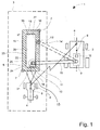
- FIG. 1 shows a schematic representation of two vehicles 1 traveling in parallel next to one another in plan view.
- a vehicle consists of a self-propelled harvester 2 in the form of a combine with the known elements eg Emtegutancevoriques, cab, grain tank, drive, wheels, etc., which will not be discussed here in detail and a transport vehicle 3, consisting of a tractor 4 and a
- a transporting vehicle 3 can also consist of a tractor 4 with integrated transport container 5, a so-called semi-trailer vehicle, for example lorries.
- the self-propelled harvester 2 may, for example, also be a forage harvester.
- the forage harvester picks up crop material from the processing field via the crop intake device, crushes the crop and delivers it to the transport vehicle 3 or transport container 5 by means of the transfer device 9, the transfer device 9 consists of a controller 12, a transfer device 10 and a transfer door 11 for the continuous delivery of the crop.
- the combine harvester 2 also takes on the Ernteguting owned crop from the edit box, crushed and separates the crop, the straw shares ejected and the grain fractions are stored in a grain tank, the Combine also has a transfer device 9, which takes over the emptying of the grain tank, wherein the overcharge of the crop from the grain tank on the transport vehicle 3 or transport container 5 by means of a transfer device 10 and a transfer flap 11 takes place.
- the transfer of the crop or the emptying of the grain tank can continuously during the Harvesting or discontinuous, Especially in the continuous harvesting of crops, it is not necessary to burden the driver in this activity in addition to other activities in order to ensure full concentration in the Erntegutage.
- the relief according to the invention is based on the fact that a crop delivery can be fully automatic, For fully automatic overcharging, it is necessary to detect the current positions of the participating vehicles 1, the harvester 2 and the transport vehicle 3 by means of a navigation system 6.
- the self-propelled harvester 2 and the transport vehicle 3, as well as its Transport container 5 are therefore equipped with GPS antennas 7.
- the navigation system 6 is necessary, on the one hand to allow the coordination between the vehicles involved 2.3 and on the other hand to capture the dimensions of the transport vehicle 3 or the transport container 5 and this specific information about the transport vehicle 3 and / or the transport container 5 a data memory (not shown). From the sum of the determined data, consisting of different machine and crop parameters, the theoretical impact point 13 of the Erntegutgutstrahls 14 is calculated on the transport container 5 and to control the transfer device 10 and transfer door 11th used. In order to further reduce crop losses during the overloading of the crop, it is proposed according to the invention to define a permissible area 15 for the impact point 13 of the crop jet 14 which lies within the boundary of the loading area 17. The loading area 17 is determined by the contour of the transport container 5.
- an edge zone 16 is formed around the transport container contour 18, which constitutes a blocking zone 23 for the point of impact 13 of the harvest crop 14.
- the edge zone 16 is defined on the one hand by the outer boundary 19 and on the other hand formed by the inner boundary 20.
- the outer boundary 19 of the edge zone 16 is defined by the transport container contour 18, wherein the inner boundary 20 of the edge zone 16 defines the admissibility area 15 for the theoretical loading zone 22.
- the loading zone 22 and the edge zone 16 together form the loading area 17.
- the inner boundary 19 of the edge zone 16 can be changed during the harvesting operation or during the overcharge and thus adapted to the harvesting conditions, wherein the inner boundary 20 of the edge zone 16, in the present example the FIG. 1 , is formed of four inner boundary lines 24, 25, 26, 27. In each case two boundary lines 24. 26 and 25, 27 are spaced approximately parallel and predetermined by the transport container contour 18. Other geometrical transport container contours 18 result in different geometric inner boundary lines, a change of the inner boundary 20 of the edge zone 16 may affect all four boundary lines 24, 25, 26, 27.
- all four boundary lines 24, 26, 26, 27 are changed with the change of the diameter of the slip cone 21, or two boundary lines 25, 27 with the slope of the Transport container 5, which is in an inclined position with the field floor
- Another exemplary change of the inner boundary line 24,26 may result from the consideration of the wind conditions. Also, a change of only one of the four boundary lines is possible.
- This theoretical loading zone 22 is controlled by the transfer device 10, wherein the transfer device 10 may consist of a Korntankleerrohr at a combine harvester and a forage harvester at a forage harvester, the overcharging of the crop from the harvester 2 to a transport vehicle 3 can be continuous or discontinuous.
- the transmission system 8 provides a data transmission path. By means of this data transmission path data for the coordination of the vehicles and the control of the transfer device 10 can be exchanged.
Landscapes
- Life Sciences & Earth Sciences (AREA)
- Environmental Sciences (AREA)
- Harvester Elements (AREA)
- Harvesting Machines For Specific Crops (AREA)
- Guiding Agricultural Machines (AREA)
- Combines (AREA)
- Management, Administration, Business Operations System, And Electronic Commerce (AREA)
- Harvesting Machines For Root Crops (AREA)
Abstract
Description
Die vorliegende Erfindung bezieht sich allgemein auf das Gebiet der Landwirtschaft und der Verarbeitung von Ernteerzeugnissen. Hierzu werden Fahrzeuge, insbesondere selbstfahrende landwirtschaftliche Erntemaschinen, welche zur Aufnahme der Ernte und zur Verarbeitung des Gutes dienen, eingesetzt. Bei den selbstfahrenden landwirtschaftlichen Erntemaschinen handelt es sich in der Regel um Mähdrescher, Feldhäcksler und alle Arten von Rodern, die mit Einrichtungen zur Verarbeitung und Vorrichtungen zur Förderung des Erntegutes ausgestattet sind. Eine solche Fördervorrichtung ist beispielsweise die Übergabevorrichtung, mit der das gesamte Erntegut auf ein Transportfahrzeug oder einen angehängten Transportbehälter übergeben wird. Die Erntemaschinen nehmen während des Erntevorganges kontinuierlich Erntegut auf, bearbeiten es in bekannter Art und Weise und geben das Erntegut entweder kontinuierlich, beispielsweise bei einem selbstfahrenden Feldhäcksler, oder nach einer Zwischenspeicherung, beispielsweise bei einem Mähdrescher, an ein neben- oder hinterherfahrendes Transportfahrzeug ab. Die Abgabe des Erntegutes erfolgt über die Überladeeinrichtung, die bei einem Mähdrescher u.a. aus einer Übergabevorrichtung besteht. Die Übergabevorrichtung kann bei einem Mähdrescher aus einem Korntankauslaufrohr und bei einem Feldhäcksler aus einem Auswurfkrümmer gebildet werden, an deren Ende sich eine Überladeklappe befindet. Die möglichst verlustarme Übergabe des Erntegutes zwischen einer selbstfahrenden Erntemaschine und einen Transportfahrzeug erfolgt mit Hilfe einer Übergabevorrichtung. Die Übergabevorrichtung ist dazu mit einer Steuerungseinrichtung, zur automatischen oder manuellen Einstellung, ausgestattet und die selbstfahrende landwirtschaftliche Erntemaschine, zur Erfassung der Positionen der beteiligten Fahrzeuge, mit einem Navigationssystem,The present invention relates generally to the field of agriculture and the processing of harvested produce. For this purpose, vehicles, in particular self-propelled agricultural harvesting machines, which serve to receive the harvest and to process the goods used. Self-propelled agricultural harvesting machines are generally combine harvesters, forage harvesters and all types of harvesters equipped with processing and harvesting equipment. Such a conveying device is, for example, the transfer device, with which the entire crop is transferred to a transport vehicle or an attached transport container. The harvesting machines continuously pick up crops during the harvesting process, process them in a known manner and deliver the crop either continuously, for example in a self-propelled forage harvester, or after intermediate storage, for example in a combine harvester, to a side-by-side or trailing transport vehicle. The delivery of the crop takes place via the transfer device, which consists of a combine among others from a transfer device. The transfer device can be formed in a combine harvester from a grain tank outlet pipe and a forage harvester from a chute, at the end of which a Überladeklappe is located. The lowest possible transfer of the crop between a self-propelled harvester and a transport vehicle using a transfer device. The transfer device is for this purpose equipped with a control device for automatic or manual adjustment, and the self-propelled agricultural harvester, for detecting the positions of the vehicles involved, with a navigation system,
Solche Fahrzeuge, insbesondere selbstfahrende landwirtschaftliche Erntemaschinen mit einer Überladeeinrichtung zur Abgabe des Erntegutes an ein Transportfahrzeug oder Transportbehälter, wobei die Einrichtung eine Übergabevorrichtung, eine Steuerung für die Stellung der Übergabevorrichtung, der Überladeklappe und des Erntegutaustrittstrahls, sowie ein Navigationssystem zur Ermittlung der Relativpositionen der beteiligten Fahrzeuge und einer Datenübertragung zwischen den Fahrzeugen, aufweist, sind aus dem Stand der Technik hinreichend bekannt Bekannt sind hierbei verschiedene Methoden zur automatischen Befüllung von Transportfahrzeugen mit einem Feldhäcksler durch automatische Bewegungen des Auswurfkrümmers. Ein Beispiel ist aus der
Um den vorgenannten Nachteil zu beseitigen, werden in diesem Zusammenhang verschiedene Methoden zur Erfassung der Position der beteiligten Fahrzeuge und deren Abmessungen im Stand der Technik beschrieben.In order to eliminate the aforementioned disadvantage, various methods for detecting the position of the involved vehicles and their dimensions in the prior art are described in this connection.
Eine solche Vorrichtung zur Erfassung der Position und Bestimmung der Abmessungen von selbstfahrenden landwirtschaftlichen Fahrzeugen wird in der
Um den Verlust von Erntegut beim Überladen weiter zu reduzieren bzw. zu minimieren, ist es erforderlich, den Auftreffpunkt des Erntegutes auf dem Transportfahrzeug noch genauer zu definieren und zu steuern.In order to further reduce or minimize the loss of crop during overloading, it is necessary to more precisely define and control the point of impact of the crop on the transport vehicle.
In der Offenlegungsschrift
Der Erfindung liegt daher die Aufgabe zugrunde, eine Steuerung bzw. ein Steuerungssystem der eingangs genannten Art zu schaffen, welche die genannten Nachteile der bekannten Anordnungen aus dem Stand der Technik vermeidet und eine technische Lösung anzugeben, die es ermöglicht, den Fahrer beim Überladevorgang des Erntegutes derart zu unterstützen bzw. zu entlasten, dass der Verlust von Erntegut durch schlecht koordiniertes Überladen, unübersichtliche Transportfahrzeuge oder bei Überladung in Nachteinsätzen, vermieden werden kann.The invention is therefore an object of the invention to provide a control system or a control system of the type mentioned, which avoids the disadvantages of the known arrangements of the prior art and to provide a technical solution that allows the driver during the transfer process of the crop to support or relieve such that the loss of crop by poorly coordinated overloading, unclear transport vehicles or overloading in night operations, can be avoided.
Erfindungsgemäß wird dieses Problem durch die kennzeichnenden Merkmale des Patentanspruchs 1 gelöst. Vorteilhafte Ausgestaltungen und Weiterbildungen der Erfindung ergeben sich aus den nachstehenden Unteransprüchen und den nachfolgenden Beschreibungen.According to the invention this problem is solved by the characterizing features of
Um Fahrzeuge mit diesen Merkmalen der vorliegenden Erfindung herzustellen, insbesondere selbstfahrende landwirtschaftliche Erntemaschinen, ausgestattet mit einem Navigationssystem zur Ermittlung der Relativpositionen der beteiligten Fahrzeuge, einem Datenübertragungssystem zum Austausch von Daten zwischen den Fahrzeugen, einer Überladeeinrichtung zur Abgabe des Erntegutes an ein Transportfahrzeug, wobei die Einrichtung eine Übergabevorrichtung, eine Steuerung zur Positionierung einer Übergabevorrichtung und einer Überladeklappe aufweist, wird erfindungsgemäß vorgeschlagen, die aus dem Stand der Technik bekannten Steuerungen so zu gestalten, dass die Abgabe des Erntegutes auf das Transportfahrzeug bzw. dessen Transportbehälter nur in einen zulässigen Bereich erfolgtTo produce vehicles with these features of the present invention, in particular self-propelled agricultural harvesters, equipped with a navigation system for determining the relative positions of the vehicles involved, a data transfer system for exchanging data between the vehicles, a transfer device for delivering the crop to a transport vehicle, wherein the device a transfer device, a controller for positioning a transfer device and a transfer hatch, the invention proposes to make known from the prior art controls so that the delivery of the crop on the transport vehicle or its transport container takes place only in a permissible range
D.h., dass der gewünschte Auftreffpunkt des Erntegutstrahls in einem zulässigen Bereich liegen sollte, Der Zulässigkeitsbereich wird durch eine Randzone begrenzt, wobei derZulässigkeitsberesch und die Randzone die Fläche des Transportbehälters abbilden, Die Fläche des Transportbehälters wird durch die Transportbehälterkontur bzw. durch die Abmessungen des Transportfahrzeuges und/oder des Tr3r!sportbeha!ters gebildet Die Transportbehaiterkontur bildet dabei die äußere Begrenzung der Randzone, Die äußere Begrenzung der Randzone ist abhängig von der Geometrie des Transportfahrzeuges und/oder des Transportbehälters und ist deshalb variabel einstellbar. Die Erfassung der Abmessungen und die Lagebestimmung des Transportfahrzeuges/ Transportbehälters können auf einem sensorischen Weg, beispielsweise über ein Navigationssystem mit GPS- Antennen am Transportbehälter und/oder aus einer Kombination aus Sensoren und mathematischem Modell erfolgen, Die innere Begrenzung der Randzone hingegen liegt innerhalb der Begrenzung der Fläche des Transportbehälters und ist Teil der Ladefläche, wobei die innere Begrenzung der Randzone im Sonderfall mit der äußeren Begrenzung der Randzone, teilweise oder im Ganzen, zusammenfallen kann.That is, that the desired impact point of the Erntegutstrahls should be within a permissible range, The admissibility range is limited by an edge zone, the Zulässigkeitsberesch and the edge zone depict the surface of the transport container, The surface of the transport container is by the transport container contour or by the dimensions of the transport vehicle and / or the Tr 3 r ! Sportbeha ters formed The transport container contour forms the outer Limiting the edge zone, The outer boundary of the edge zone depends on the geometry of the transport vehicle and / or the transport container and is therefore variably adjustable. The detection of the dimensions and the orientation of the transport vehicle / transport container can be done on a sensory path, for example via a navigation system with GPS antennas on the transport container and / or a combination of sensors and mathematical model, the inner boundary of the edge zone, however, lies within the boundary the surface of the transport container and is part of the loading area, wherein the inner boundary of the edge zone in the special case with the outer boundary of the edge zone, partially or in total, can coincide.
D.h., dass durch die variabel einstellbare innere Begrenzung der Randzone während des Überladevorganges auch die Größe des Zulässigkeitsbereiches für den Auftreffpunkt des Erntegutstrahles einstellbar ist. Die Einstellung der Größe des Zulässigkeitsbereiches richtet sich nach dem Bedarf bzw. den Erntebedingungen, Der Bedarf der Einstellung ist also abhängig von verschiedenen Parametern, wie z.B. den maschinen- und erntegutabhängigen Parametern, wodurch eine Änderung der Einstellung der Randzone, uzw. der inneren und/oder äußeren Begrenzung der Randzone erfolgen kann.In other words, the size of the admissibility range for the impact point of the crop stream can also be set by the variably adjustable inner boundary of the edge zone during the transfer operation. The setting of the size of the range of admissibility depends on the need or the harvest conditions. The need for the setting is thus dependent on various parameters, such as e.g. the machine- and crop-dependent parameters, whereby a change in the setting of the edge zone, uzw. the inner and / or outer boundary of the edge zone can take place.
Mit Änderung von erntegutabhängigen Parametern kann somit eine Änderung der Einstellung der inneren Begrenzung der Randzone erfolgen, Erntegutabhängige Parameter sind beispielsweise der Schüttkegel des geförderten Erntegutes, der durch die unterschiedliche Feuchtigkeit des Erntegutes in der Größe variieren kann. Trockenes Erntegut ergibt einen kleinen Schüttkegel und feuchtes Erntegut hingegen einen großen Schüttkegel, Mit Änderung der Größe des Schüttkegels soll auch die Einstellung der inneren Begrenzung der Randzone und somit die Größe des Zulässigkeitsbereiches für den Auftreffpunkt des Erntegutstrahles variiert werden, Einfluss auf den Schüttkegel hat auch die Sorte und/oder die Häcksellänge des Erntegutes.Thus, a change in the setting of the inner boundary of the edge zone can take place with the change of crop-dependent parameters. Crop-dependent parameters are, for example, the bulk cone of the conveyed crop, which can vary in size due to the different moisture content of the crop. With a change in the size of the bulk cone, the setting of the inner boundary of the edge zone and thus the size of the admissibility range for the point of impact of the Erntegutstrahles should be varied, the bulk cone has also the Variety and / or the shred length of the crop.
Auch Änderungen der maschinenabhängigen Parameter können eine Änderung der inneren Begrenzung der Randzone nach sich ziehen. Maschinenabhängige Parameter sind beispielsweise die Fahrgeschwindigkeit der Erntemaschine und/oder des Transportfahrzeuges, sowie die Relativgeschwindigkeit der Fahrzeuge zueinander, wodurch die innere Begrenzung der Randzone während des Überladevorganges verändert und den neuen Begebenheiten angepasst werden kann. Ein weiterer maschinenabhängiger Parameter berücksichtigt die Schräglage des Ernte- und Transportfahrzeuges, also die Neigung des Feldes oder die Neigung des Transportfahrzeuges und/oder der Erntemaschine zum Feldboden. Auch diese Parameter gehen bei der Festlegung der inneren Begrenzung der Randzone in die Auswertung für die Steuerung ein. In die Auswertung für die Steuerung der Übergabevorrichtung können auch Parameter von Sensoren eingehen, welche die Umgebuiigsbedingungen erfassen. Parameter von Umgebungsbedingungen sind beispielsweise die Windrichtung und die Windgeschwindigkeit,Changes to the machine-dependent parameters may also result in a change in the inner boundary of the edge zone. machine-dependent Parameters are, for example, the driving speed of the harvester and / or the transport vehicle, as well as the relative speed of the vehicles to each other, whereby the inner boundary of the edge zone can be changed and adapted to the new events during the Überladevorgang. Another machine-dependent parameter takes into account the skew of the harvesting and transport vehicle, ie the inclination of the field or the inclination of the transport vehicle and / or the harvester to the field soil. These parameters are also included in the evaluation for the control when defining the inner boundary of the edge zone. In the evaluation for the control of the transfer device and parameters of sensors may be received, which detect the ambient conditions. Parameters of environmental conditions are, for example, the wind direction and the wind speed,
Die zwischen der inneren und äußeren Begrenzung der Randzone gebildete Fläche stellt für den Auftreffpunkt des Erntegutstrahls eine Sperrzone dar. In diesen Sperrzonen darf kein Erntegut auftreffen, Die Sperrzone bildet für die Überladung des Erntegutes eine Sicherheitszone zum Rand des Transportbehälters, die nach Bedarf vergrößert oder verkleinert werden kann. Der theoretische Auftreffpunkt des Erntegutstrahls auf dem Transportfahrzeug bzw. Transportbehälter wird gemäß den beschriebenen Verfahren aus dem Stand der Technik der
Ein konkretes Ausführungsbeispiel der Erfindung, ist in der Zeichnung, anhand eines Überladevorganges, rein schematisch dargestellt und wird nachfolgend näher beschrieben. Es zeigt:
- Fig. 1
- eine schematische Darstellung von beteiligten Fahrzeugen während des Ernte- und Überladevorganges, wobei das eine Fahrzeug eine Erntemaschine und das Andere ein Erntetransportfahrzeug mit dem erfindungsgemäßen Überladebereich ist.
- Fig. 1
- a schematic representation of participating vehicles during the harvesting and Überladevorganges, wherein the one vehicle is a harvester and the other is a harvesting transport vehicle with the Überladebereich invention.
Die F!g.1 1 zeigt in schematischer Darstellung zwei parallel nebeneinander fahrende Fahrzeuge 1 in Draufsicht. Ein Fahrzeug besteht aus einer selbstfahrenden Erntemaschine 2 in der Form eines Mähdreschers mit den bekannten Elementen z.B. Emtegutaufnahmevorrichtung, Fahrerkabine, Korntank, Fahrantrieb, Laufräder usw., auf die hier nicht näher eingegangen werden soll und einem Transportfahrzeug 3, bestehend aus einer Zugmaschine 4 und einem anhängbaren Transportbehälter 5. Ein Transportfahrzeug 3 kann auch aus einer Zugmaschine 4 mit integriertem Transportbehälter 5 bestehen, einem so genannten AufliegerfahrzeLig, beispielsweise Lastkraftwagen.
Bei der selbstfahrenden Erntemaschine 2 kann es sich beispielsweise aber auch um einen Feldhäcksler handeln, Der Feldhäcksler nimmt über die Erntegutaufnahmeeinrichtung Erntegut vom Bearbeitungsfeld auf, zerkleinert das Erntegut und gibt es mittels der Überladeeinrichtung 9 an das Transportfahrzeug 3 oder Transportbehälter 5 ab, wobei die Überladeeinrichtung 9 aus einer Steuerung 12, einer Übergabevorrichtung 10 und einer Überladeklappe 11 für die kontinuierliche Abgabe des Erntegutes, besteht.
Der Mähdrescher 2 nimmt ebenfalls über die Erntegutaufnahmeeinrichtung Erntegut vom Bearbeitungsfeld auf, zerkleinert und trennt das Erntegut, wobei die Strohanteile ausgeworfen und die Kornanteile in einem Korntank gespeichert werden, Der Mähdrescher besitzt gleichfalls eine Überladeeinrichtung 9, welche die Entleerung des Korntanks übernimmt, wobei die Überladung des Erntegutes aus dem Korntank auf das Transportfahrzeug 3 bzw. Transportbehälter 5 mittels einer Übergabevorrichtung 10 und einer Übergabeklappe 11 erfolgt. Die Übergabe des Erntegutes bzw, die Entleerung des Korntanks kann kontinuierlich während der
Erntefahrt oder diskontinuierlich erfolgen, Gerade bei der kontinuierlichen Erntegutaufnahme ist es nohvendig, den Fahrer bei dieser Tätigkeit nicht zusätzlich mit anderen Tätigkeiten zu belasten, um die volle Konzentration bei der Erntegutaufnahme zu gewährleisten.
Die erfindungsgemäße Entlastung beruht nun darauf, dass eine Erntegutübergabe vollautomatisch erfolgen kann, Zur vollautomatischen Überladung ist es erforderlich, die aktuellen Positionen der beteiligten Fahrzeuge 1, der Erntemaschine 2 und des Transportfahrzeuges 3 mittels eines Navigationssystem 6 zu erfassen. Die selbstfahrende Erntemaschine 2 und das Transportfahrzeug 3, sowie dessen
Transportbehälter 5 sind deshalb mit GPS- Antennen 7 ausgerüstet. Das Navigationssystem 6 ist notwendig, um einerseits die Koordination zwischen den beteiligten Fahrzeugen 2,3 zu ermöglichen und andererseits die Abmessungen des Transportfahrzeuges 3 bzw, des Transportbehälters 5 zu erfassen und diese spezifischen Angaben über das Transportfahrzeug 3 und/oder den Transportbehälter 5 einem Datenspeicher (nicht dargestellt) zu zuführen. Diese speziellen Daten werden zur exakten Steuerung 12 der Übergabevorrichtung 10 benötigt, Aus der Summe der ermittelten Daten, bestehend aus unterschiedlichen Maschinen- und Erntegutparametem, wird der theoretische Auftreffpunkt 13 des Erntegutgutstrahls 14 auf dem Transportbehälter 5 berechnet und zur Steuerung der Übergabevorrichtung 10 und Übergabeklappe 11 herangezogen.
Um die Erntegutverluste bei der Überladung des Erntegutes weiter zu reduzieren, wird erfindungsgemäß, vorgeschlagen, für den Auftreffpunkt 13 des Erntegutstrahles 14 einen Zulässigkeitsbereich 15, der innerhalb der Begrenzung der Ladefläche 17 liegt, zu definieren. Die Ladefläche 17 wird durch die Kontur des Transportbehälters 5 bestimmt. Zur Reduzierung der Erntgutverluste ist es notwendig, den Erntegutstrahl 14 nicht bis an die Kontur des Transportbehälters 5 heranzuführen, sondern einen gewissen Abstand einzuhalten, Der Abstand sollte aber aufgrund der unterschiedlichen maschinen- und erntegutabhängigen Parameter variabel einstellbar sein. Um für den Auftreffpunkt 13 des Erntegutstrahles 14 einen definierten Abstand zur Transportbehälterkontur 18 zu erhalten, wird um die Transportbehälterkontur 18 eine Randzone 16 gebildet, die für den Auftreffpunkt 13 des Erntegutstrahtes 14 eine Sperrzone 23 darstellt, Die Randzone 16 wird einerseits durch die äußere Begrenzung 19 und andererseits durch die innere Begrenzung 20 gebildet. Die äußere Begrenzung 19 der Randzone 16 wird durch die Transportbehälterkontur 18 festgelegt, wobei die innere Begrenzung 20 der Randzone 16 den Zulässigkeitsbereich 15 für die theoretische Ladezone 22 definiert, Die Ladezone 22 und die Randzone 16 bilden gemeinsam die Ladefläche 17.
Wie bereits zuvor angegeben, kann die innere Begrenzung 19 der Randzone 16 während des Erntebetriebes bzw. während der Überladung verändert und somit den Erntebedingungen angepasst werden, wobei die innere Begrenzung 20 der Randzone 16, im vorliegenden Beispiel der
Diese theoretische Ladezone 22 wird von der Übergabevorrichtung 10 angesteuert, wobei die Übergabevorrichtung 10 bei einem Mähdrescher aus einem Korntankleerrohr und bei einem Feldhäcksler aus einem Auswurfkrümmer bestehen kann, Die Überladung des Erntegutes von der Erntemaschine 2 auf ein Transportfahrzeug 3 kann kontinuierlich oder diskontinuierlich erfolgen. Zwischen der Erntemaschine 2 und dem Transportfahrzeug 3 besteht eine weitere Verbindung, bestehend aus einem übertragungssystem 8. Das Übertragungssystem 8 stellt eine Datenübertragungsstrecke zur Verfügung. Mittels dieser Datenübertragungsstrecke können Daten für die Koordination der Fahrzeuge und die Steuerung der Übergabevorrichtung 10 ausgetauscht werden.FIG. 1 shows a schematic representation of two
The self-
The
Harvesting or discontinuous, Especially in the continuous harvesting of crops, it is not necessary to burden the driver in this activity in addition to other activities in order to ensure full concentration in the Erntegutaufnahme.
The relief according to the invention is based on the fact that a crop delivery can be fully automatic, For fully automatic overcharging, it is necessary to detect the current positions of the participating
Transport container 5 are therefore equipped with GPS antennas 7. The
In order to further reduce crop losses during the overloading of the crop, it is proposed according to the invention to define a
As already stated above, the
This
- 11
- Fahrzeugevehicles
- 22
- Erntemaschineharvester
- 33
- Transportfahrzeugtransport vehicle
- 44
- Zugmaschinetractor
- 55
- Transportbehältertransport container
- 66
- Navigationssystemnavigation system
- 77
- GPS- AntenneGPS antenna
- 88th
- Datenübertragung$systemData transfer $ system
- 99
- ÜberladeeinrichtungTransfer device
- 1010
- ÜbergabevorrichtungTransfer device
- 1111
- ÜberladeklappeTransfer flap
- 1212
- Steuerungcontrol
- 1313
- Auftreffpunktof impact
- 1414
- Erntegutstrahlcrop discharge flow
- 1515
- Zulässigkeitsbereichallowance range
- 1616
- Randzoneborder zone
- 1717
- Flächearea
- 1818
- TransportbehälterkonturTransport container contour
- 1919
- Äußere BegrenzungOuter limit
- 2020
- Innere BegrenzungInner boundary
- 2121
- Schüttkegelangle of repose
- 2222
- LadezoneLoading Zone
- 2323
- Sperrzoneexclusion zone
- 2424
- BegtenzurigslinieBegtenzurigslinie
- 2525
- Begrenzungslinieboundary line
- 2626
- Begrenzungslinieboundary line
- 2727
- Begrenzungs!inieLimiting inie!
Claims (21)
- Vehicles (1), in particular self-propelled agricultural harvesting machines (2) equipped with a navigation system (6) for ascertaining the relative positions of the vehicles (2, 3) involved, a data transmission system (8) for the exchange of data between the vehicles (2, 3), a transfer device (9) for discharge of the crop material to a transport vehicle (3), wherein the device (9) has a transfer apparatus (10), a control (12) for positioning a transfer apparatus (10) and a transfer flap (11),
characterised in that
the impingement point (13) of the jet of crop material (14) is in an admissibility region delimited by an edge zone (16), and
the admissibility region (15) and the edge zone (16) define the surface of the transport container (5). - Vehicles (1) according to claim 1 characterised in that the surface (17) of the transport container (5) is formed by the transport container contour (18).
- Vehicles (1) according to claims 1 to 2 characterised in that the transport container contour (18) forms the outer boundary (19) of the edge zone (16).
- Vehicles (1) according to claims 1 to 2 characterised in that the outer boundary (19) is variably adjustable.
- Vehicles (1) according to claims 1 to 3 characterised in that the inner boundary (20) of the edge zone (16) lies within the boundary (18) of the load surface (17).
- Vehicles (1) according to claims 1 to 4 characterised in that the inner boundary (20) partially or entirely coincides with the outer boundary (19) of the edge zone (16).
- Vehicles (1) according to one or more of the preceding claims characterised in that the size of the admissibility region (15) for the impingement point (13) of the jet of crop material (14) is also adjusted by the variably adjustable inner boundary (20) of the edge zone (16).
- Vehicles (1) according to one or more of the preceding claims characterised in that a change in the setting of the edge zone (16) is effected with a change in the machine-dependent and crop material-dependent parameters.
- Vehicles (1) according to one or more of the preceding claims characterised in that a change in the setting of the inner boundary (20) of the edge zone (16) is effected with a change in the crop material-dependent parameters.
- Vehicles (1) according to one or more of the preceding claims characterised in that a change in the inner boundary (20) of the edge zone (16) is effected with a change in the talus cone.
- Vehicles (1) according to one or more of the preceding claims characterised in that a change in the inner boundary (20) of the edge zone (16) is effected with a change in the machine-dependent parameters.
- Vehicles (1) according to one or more of the preceding claims characterised in that a change in the inner boundary (20) of the edge zones (16) is effected with a change in the relative speed.
- Vehicles (1) according to one or more of the preceding claims characterised in that the surface formed between the inner and outer boundaries (19, 20) of the edge zone (16) forms a barrier zone (23) for the impingement point (13) of the jet of crop material (14).
- Vehicles (1) according to one or more of the preceding claims characterised in that the theoretically ascertained position of the impingement point (13) decides about the start of the transfer operation.
- Vehicles (1) according to one or more of the preceding claims characterised in that the transfer operation is not started when the impingement point (13) of the jet of crop material (14) is in the barrier zone (23).
- Vehicles (1) according to one or more of the preceding claims characterised in that the transfer operation is started when the impingement point (13) of the jet of crop material (14) is in the admissibility region (15).
- Vehicles (1) according to one or more of the preceding claims characterised in that the transfer operation is shut down when the impingement point (13) of the jet of crop material (14) leaves the admissibility region (15).
- Vehicles (1) according to one or more of the preceding claims characterised in that the inner boundary (20) of the edge zone (16) is formed from four boundary lines (24, 25, 26, 27).
- Vehicles (1) according to one or more of the preceding claims characterised in that the transfer apparatus (10) in a combine harvester is formed from a grain tank emptying pipe.
- Vehicles (1) according to one or more of the preceding claims characterised in that the transfer apparatus (10) in the case of a forage harvester is formed from a discharge pipe bend.
- Vehicles (1) according to one or more of the preceding claims characterised in that transfer of the crop material from the harvesting machine (2) on to a transport vehicle (3) is effected continuously or discontinuously.
Applications Claiming Priority (1)
| Application Number | Priority Date | Filing Date | Title |
|---|---|---|---|
| DE102007016670A DE102007016670A1 (en) | 2007-04-04 | 2007-04-04 | Self-propelled agricultural harvester with controllable transfer device |
Publications (3)
| Publication Number | Publication Date |
|---|---|
| EP1977640A1 EP1977640A1 (en) | 2008-10-08 |
| EP1977640B1 true EP1977640B1 (en) | 2011-02-09 |
| EP1977640B2 EP1977640B2 (en) | 2014-02-26 |
Family
ID=39278307
Family Applications (1)
| Application Number | Title | Priority Date | Filing Date |
|---|---|---|---|
| EP07123613.7A Not-in-force EP1977640B2 (en) | 2007-04-04 | 2007-12-19 | Self-driving agricultural harvester with controllable transfer device |
Country Status (6)
| Country | Link |
|---|---|
| US (1) | US8428829B2 (en) |
| EP (1) | EP1977640B2 (en) |
| AT (1) | ATE497689T1 (en) |
| DE (2) | DE102007016670A1 (en) |
| RU (1) | RU2476061C2 (en) |
| UA (1) | UA95459C2 (en) |
Cited By (3)
| Publication number | Priority date | Publication date | Assignee | Title |
|---|---|---|---|---|
| US11930738B2 (en) | 2021-06-28 | 2024-03-19 | Deere & Company | Closed loop control of filling mechanisms |
| US11980134B2 (en) | 2021-03-09 | 2024-05-14 | Deere & Company | Operator commanded placement for control of filling mechanisms |
| US12004449B2 (en) | 2021-03-24 | 2024-06-11 | Deere & Company | Control system for controlling filling mechanisms in communication with a mobile device |
Families Citing this family (103)
| Publication number | Priority date | Publication date | Assignee | Title |
|---|---|---|---|---|
| DE102008014001A1 (en) * | 2008-03-13 | 2009-09-17 | Claas Selbstfahrende Erntemaschinen Gmbh | Agricultural harvester with a transfer device |
| US8145393B2 (en) * | 2008-09-17 | 2012-03-27 | Cnh America Llc | System and method employing short range communications for interactively coordinating unloading operations between a harvester and a grain transport |
| US8689527B2 (en) * | 2009-06-12 | 2014-04-08 | Reiter Affiliated Companies, Llc | Harvest aid machine |
| US8991140B2 (en) * | 2009-06-12 | 2015-03-31 | Reiter Affilated Companies, LLC | Harvest aid machine |
| US8602135B2 (en) * | 2009-06-25 | 2013-12-10 | Deere & Company | Drive quad module |
| US8789563B2 (en) * | 2010-10-12 | 2014-07-29 | Deere & Company | Intelligent grain bag loader |
| DE102011000057A1 (en) * | 2011-01-07 | 2012-07-12 | Claas Selbstfahrende Erntemaschinen Gmbh | Combine harvester with a distribution device for distributing shredded crops |
| US9002591B2 (en) | 2011-02-18 | 2015-04-07 | Cnh Industrial America Llc | Harvester spout control system and method |
| DE102011002071A1 (en) * | 2011-04-15 | 2012-10-18 | Claas Selbstfahrende Erntemaschinen Gmbh | System and method for controlling crop overload |
| US20130022430A1 (en) * | 2011-07-20 | 2013-01-24 | Anderson Noel W | Material transfer system |
| US8544574B2 (en) * | 2011-07-20 | 2013-10-01 | Deere & Company | Grain cart capable of self-propulsion |
| DE102011082052B4 (en) | 2011-09-02 | 2015-05-28 | Deere & Company | Arrangement and method for the automatic overloading of crop material from a harvester onto a transport vehicle |
| US8868304B2 (en) | 2012-02-10 | 2014-10-21 | Deere & Company | Method and stereo vision system for facilitating the unloading of agricultural material from a vehicle |
| US9861040B2 (en) | 2012-02-10 | 2018-01-09 | Deere & Company | Method and stereo vision system for facilitating the unloading of agricultural material from a vehicle |
| US9392746B2 (en) | 2012-02-10 | 2016-07-19 | Deere & Company | Artificial intelligence for detecting and filling void areas of agricultural commodity containers |
| DE102012215013A1 (en) * | 2012-08-23 | 2014-02-27 | Wirtgen Gmbh | Self-propelled milling machine, as well as method for unloading milled material |
| DE102013012026A1 (en) * | 2013-07-19 | 2015-01-22 | Claas Selbstfahrende Erntemaschinen Gmbh | Vehicle network, apparatus and method for its coordination |
| DE102013012027A1 (en) * | 2013-07-19 | 2015-01-22 | Claas Selbstfahrende Erntemaschinen Gmbh | Self-propelled harvester and vehicle network |
| BE1021158B1 (en) * | 2013-07-24 | 2015-10-30 | Cnh Industrial Belgium Nv | HARVESTING MACHINES FOR USE IN AGRICULTURE |
| BE1021164B1 (en) | 2013-10-28 | 2016-01-18 | Cnh Industrial Belgium Nv | DISCHARGE SYSTEMS |
| DE102014100136A1 (en) * | 2014-01-08 | 2015-07-09 | Claas Selbstfahrende Erntemaschinen Gmbh | harvester |
| BR102015013228B1 (en) | 2014-06-13 | 2020-11-24 | Cnh Industrial America Llc | CONTROL SYSTEM AND METHOD FOR AN AGRICULTURAL VEHICLE |
| BR102015013229B8 (en) | 2014-06-13 | 2021-12-14 | Cnh Ind America Llc | Control system for an agricultural vehicle and method for calibrating the alignment of a conveyor outlet of an agricultural vehicle with a storage compartment |
| DE102015109799A1 (en) * | 2015-06-18 | 2016-12-22 | Claas E-Systems Kgaa Mbh & Co Kg | Method for synchronizing two independent, self-propelled agricultural machines |
| PL3165078T3 (en) * | 2015-11-06 | 2020-11-02 | Exel Industries | Crop transfer device and corresponding method |
| US9675008B1 (en) | 2016-02-29 | 2017-06-13 | Cnh Industrial America Llc | Unloading arrangement for agricultural harvesting vehicles |
| US10152891B2 (en) * | 2016-05-02 | 2018-12-11 | Cnh Industrial America Llc | System for avoiding collisions between autonomous vehicles conducting agricultural operations |
| US10159191B2 (en) * | 2016-09-23 | 2018-12-25 | Deere & Company | Harvester grain unloader |
| EP3315005B1 (en) | 2016-10-28 | 2022-04-06 | Deere & Company | Stereo vision system for managing the unloading of an agricultural material from a vehicle |
| DE102016222589B4 (en) | 2016-11-16 | 2020-01-16 | Wirtgen Gmbh | Self-propelled milling machine and method for controlling a self-propelled milling machine |
| DE102017220869A1 (en) | 2017-11-22 | 2019-05-23 | Wirtgen Gmbh | Self-propelled milling machine, method for automatically loading a means of transport with milled material, as well as road or soil treatment unit |
| US11672203B2 (en) | 2018-10-26 | 2023-06-13 | Deere & Company | Predictive map generation and control |
| US11641800B2 (en) | 2020-02-06 | 2023-05-09 | Deere & Company | Agricultural harvesting machine with pre-emergence weed detection and mitigation system |
| US11653588B2 (en) | 2018-10-26 | 2023-05-23 | Deere & Company | Yield map generation and control system |
| US11957072B2 (en) | 2020-02-06 | 2024-04-16 | Deere & Company | Pre-emergence weed detection and mitigation system |
| US11240961B2 (en) | 2018-10-26 | 2022-02-08 | Deere & Company | Controlling a harvesting machine based on a geo-spatial representation indicating where the harvesting machine is likely to reach capacity |
| US11589509B2 (en) | 2018-10-26 | 2023-02-28 | Deere & Company | Predictive machine characteristic map generation and control system |
| US11079725B2 (en) | 2019-04-10 | 2021-08-03 | Deere & Company | Machine control using real-time model |
| US11178818B2 (en) | 2018-10-26 | 2021-11-23 | Deere & Company | Harvesting machine control system with fill level processing based on yield data |
| US11467605B2 (en) | 2019-04-10 | 2022-10-11 | Deere & Company | Zonal machine control |
| US12069978B2 (en) | 2018-10-26 | 2024-08-27 | Deere & Company | Predictive environmental characteristic map generation and control system |
| US10736267B2 (en) | 2019-01-07 | 2020-08-11 | Rhhe, Llc | Automated hemp field harvester |
| DE102019104218A1 (en) | 2019-02-19 | 2020-08-20 | Wirtgen Gmbh | Work train, comprising a tillage machine and another vehicle as well as an automated distance monitoring |
| US11778945B2 (en) | 2019-04-10 | 2023-10-10 | Deere & Company | Machine control using real-time model |
| US11234366B2 (en) | 2019-04-10 | 2022-02-01 | Deere & Company | Image selection for machine control |
| US11310963B2 (en) * | 2019-10-31 | 2022-04-26 | Deere & Company | Automated fill strategy for grain cart using open-loop volumetric estimation of fill level |
| US11659788B2 (en) | 2019-12-31 | 2023-05-30 | Deere & Company | Vehicle automated unloading |
| DE102020100299A1 (en) * | 2020-01-09 | 2021-07-15 | Claas E-Systems Gmbh | Method and system for overloading crop |
| US12035648B2 (en) | 2020-02-06 | 2024-07-16 | Deere & Company | Predictive weed map generation and control system |
| US12329148B2 (en) | 2020-02-06 | 2025-06-17 | Deere & Company | Predictive weed map and material application machine control |
| US12225846B2 (en) | 2020-02-06 | 2025-02-18 | Deere & Company | Machine control using a predictive map |
| US11477940B2 (en) | 2020-03-26 | 2022-10-25 | Deere & Company | Mobile work machine control based on zone parameter modification |
| AU2021203000A1 (en) | 2020-08-04 | 2022-02-24 | Deere & Company | Control arrangement and corresponding method for controlling the transfer of agricultural crop from a harvesting machine having a crop discharging device to a transport vehicle |
| US11983009B2 (en) | 2020-10-09 | 2024-05-14 | Deere & Company | Map generation and control system |
| US11849671B2 (en) | 2020-10-09 | 2023-12-26 | Deere & Company | Crop state map generation and control system |
| US11871697B2 (en) | 2020-10-09 | 2024-01-16 | Deere & Company | Crop moisture map generation and control system |
| US12013245B2 (en) | 2020-10-09 | 2024-06-18 | Deere & Company | Predictive map generation and control system |
| US11946747B2 (en) | 2020-10-09 | 2024-04-02 | Deere & Company | Crop constituent map generation and control system |
| US11864483B2 (en) | 2020-10-09 | 2024-01-09 | Deere & Company | Predictive map generation and control system |
| US11727680B2 (en) | 2020-10-09 | 2023-08-15 | Deere & Company | Predictive map generation based on seeding characteristics and control |
| US11889788B2 (en) | 2020-10-09 | 2024-02-06 | Deere & Company | Predictive biomass map generation and control |
| US12422847B2 (en) | 2020-10-09 | 2025-09-23 | Deere & Company | Predictive agricultural model and map generation |
| US12419220B2 (en) | 2020-10-09 | 2025-09-23 | Deere & Company | Predictive map generation and control system |
| US11650587B2 (en) | 2020-10-09 | 2023-05-16 | Deere & Company | Predictive power map generation and control system |
| US12069986B2 (en) | 2020-10-09 | 2024-08-27 | Deere & Company | Map generation and control system |
| US11635765B2 (en) | 2020-10-09 | 2023-04-25 | Deere & Company | Crop state map generation and control system |
| US11592822B2 (en) | 2020-10-09 | 2023-02-28 | Deere & Company | Machine control using a predictive map |
| US11845449B2 (en) | 2020-10-09 | 2023-12-19 | Deere & Company | Map generation and control system |
| US12386354B2 (en) | 2020-10-09 | 2025-08-12 | Deere & Company | Predictive power map generation and control system |
| US11711995B2 (en) | 2020-10-09 | 2023-08-01 | Deere & Company | Machine control using a predictive map |
| US11675354B2 (en) | 2020-10-09 | 2023-06-13 | Deere & Company | Machine control using a predictive map |
| US12178158B2 (en) | 2020-10-09 | 2024-12-31 | Deere & Company | Predictive map generation and control system for an agricultural work machine |
| US11895948B2 (en) | 2020-10-09 | 2024-02-13 | Deere & Company | Predictive map generation and control based on soil properties |
| US11927459B2 (en) | 2020-10-09 | 2024-03-12 | Deere & Company | Machine control using a predictive map |
| US11874669B2 (en) | 2020-10-09 | 2024-01-16 | Deere & Company | Map generation and control system |
| US12550802B2 (en) | 2020-10-08 | 2026-02-17 | Deere & Company | Predictive machine characteristic map generation and control system |
| US11844311B2 (en) | 2020-10-09 | 2023-12-19 | Deere & Company | Machine control using a predictive map |
| US11849672B2 (en) | 2020-10-09 | 2023-12-26 | Deere & Company | Machine control using a predictive map |
| US11474523B2 (en) | 2020-10-09 | 2022-10-18 | Deere & Company | Machine control using a predictive speed map |
| US11825768B2 (en) | 2020-10-09 | 2023-11-28 | Deere & Company | Machine control using a predictive map |
| US12250905B2 (en) | 2020-10-09 | 2025-03-18 | Deere & Company | Machine control using a predictive map |
| US11889787B2 (en) | 2020-10-09 | 2024-02-06 | Deere & Company | Predictive speed map generation and control system |
| US11553649B2 (en) | 2020-11-18 | 2023-01-17 | Levi Lynn | Conveyor with shock-absorbing boom |
| US12127500B2 (en) | 2021-01-27 | 2024-10-29 | Deere & Company | Machine control using a map with regime zones |
| US11968927B2 (en) * | 2021-02-18 | 2024-04-30 | Deere & Company | Harvester with feed forward control of filling mechanisms |
| US11765993B2 (en) | 2021-05-17 | 2023-09-26 | Deere & Company | Control system detecting fill level on receiving vehicle(s) |
| US12571669B2 (en) | 2021-06-11 | 2026-03-10 | Deere & Company | Detecting and generating a rendering of fill level and distribution of material in receiving vehicle(s) |
| US20230031013A1 (en) | 2021-07-28 | 2023-02-02 | Deere & Company | System for dynamically detecting alert conditions and optimization criteria |
| US12229886B2 (en) | 2021-10-01 | 2025-02-18 | Deere & Company | Historical crop state model, predictive crop state map generation and control system |
| DE102021130011A1 (en) * | 2021-11-17 | 2023-05-17 | Deere & Company | Self-propelled agricultural work machine |
| US12310286B2 (en) | 2021-12-14 | 2025-05-27 | Deere & Company | Crop constituent sensing |
| US12302791B2 (en) | 2021-12-20 | 2025-05-20 | Deere & Company | Crop constituents, predictive mapping, and agricultural harvester control |
| US12245549B2 (en) | 2022-01-11 | 2025-03-11 | Deere & Company | Predictive response map generation and control system |
| US12520759B2 (en) | 2022-01-26 | 2026-01-13 | Deere & Company | Systems and methods for predicting material dynamics |
| US12082531B2 (en) | 2022-01-26 | 2024-09-10 | Deere & Company | Systems and methods for predicting material dynamics |
| US12295288B2 (en) | 2022-04-05 | 2025-05-13 | Deere &Company | Predictive machine setting map generation and control system |
| US12058951B2 (en) | 2022-04-08 | 2024-08-13 | Deere & Company | Predictive nutrient map and control |
| US12284934B2 (en) | 2022-04-08 | 2025-04-29 | Deere & Company | Systems and methods for predictive tractive characteristics and control |
| US12358493B2 (en) | 2022-04-08 | 2025-07-15 | Deere & Company | Systems and methods for predictive power requirements and control |
| US12298767B2 (en) | 2022-04-08 | 2025-05-13 | Deere & Company | Predictive material consumption map and control |
| CA3251651A1 (en) | 2022-08-11 | 2024-02-15 | Deere & Company | Systems and methods for predictive harvesting logistics |
| CA3251707A1 (en) * | 2022-08-11 | 2024-02-15 | Deere & Company | Systems and methods for predictive harvesting logistics |
| DE102023100539A1 (en) | 2023-01-11 | 2024-07-11 | Deere & Company | Arrangement for the automatic control of a transfer process from a harvesting machine to a transport vehicle taking into account crop properties |
Family Cites Families (16)
| Publication number | Priority date | Publication date | Assignee | Title |
|---|---|---|---|---|
| SU1752255A1 (en) * | 1990-12-29 | 1992-08-07 | Головное Специализированное Конструкторское Бюро По Комплексу Кормоуборочных Машин Производственного Объединения "Гомсельмаш" | Unloading chute of agricultural harvester |
| DE4403893A1 (en) * | 1994-02-08 | 1995-08-10 | Claas Ohg | Device for the automatic filling of loading containers with a stream of material |
| DE19531662A1 (en) * | 1995-08-29 | 1997-03-06 | Claas Ohg | Device for the automatic filling of loading containers |
| DE19647522A1 (en) † | 1996-11-16 | 1998-05-20 | Claas Ohg | Device for monitoring the overloading of goods from a working machine onto a transport vehicle |
| DE19848127A1 (en) * | 1998-10-19 | 2000-04-20 | Claas Selbstfahr Erntemasch | Device for controlling a transfer device |
| DE10064862A1 (en) | 2000-12-23 | 2002-07-11 | Claas Selbstfahr Erntemasch | Device and method for coordinating and adjusting agricultural vehicles |
| DE10064860A1 (en) * | 2000-12-23 | 2002-06-27 | Claas Selbstfahr Erntemasch | Harvested crop transfer optimisation device uses control unit providing signals for controlling velocity and steering angle of crop transport vehicle adjacent harvesting machine |
| US6682416B2 (en) * | 2000-12-23 | 2004-01-27 | Claas Selbstfahrende Erntemaschinen Gmbh | Automatic adjustment of a transfer device on an agricultural harvesting machine |
| DE10064861A1 (en) * | 2000-12-23 | 2002-06-27 | Claas Selbstfahr Erntemasch | Automatic control of a top transfer device of a combine harvester so that it correctly directs harvested grain into a collection trailer by use of satellite or GPS positioning devices |
| DE10204702A1 (en) * | 2002-02-05 | 2003-08-14 | Claas Selbstfahr Erntemasch | Location system on self-propelled agricultural machines |
| DE10240219A1 (en) * | 2002-08-28 | 2004-03-11 | Claas Selbstfahrende Erntemaschinen Gmbh | Device for controlling a transfer device |
| DE10309700B4 (en) | 2003-03-06 | 2012-07-12 | Deere & Company | Discharge device of an agricultural harvester |
| DE102004039460B3 (en) * | 2004-08-14 | 2006-04-20 | Deere & Company, Moline | A system for determining the relative position of a second agricultural vehicle with respect to a first agricultural vehicle |
| DE102004052298A1 (en) | 2004-10-06 | 2006-06-08 | Claas Selbstfahrende Erntemaschinen Gmbh | Overcharge assistance system |
| ATE546991T1 (en) * | 2007-08-03 | 2012-03-15 | Agrocom Gmbh & Co Agrarsystem Kg | AGRICULTURAL WORKING MACHINE |
| DE102008002006A1 (en) * | 2008-05-27 | 2009-12-03 | Deere & Company, Moline | Control arrangement for controlling the transfer of agricultural crop from a harvester to a transport vehicle |
-
2007
- 2007-04-04 DE DE102007016670A patent/DE102007016670A1/en not_active Withdrawn
- 2007-12-19 AT AT07123613T patent/ATE497689T1/en active
- 2007-12-19 EP EP07123613.7A patent/EP1977640B2/en not_active Not-in-force
- 2007-12-19 DE DE502007006455T patent/DE502007006455D1/en active Active
-
2008
- 2008-03-10 US US12/045,244 patent/US8428829B2/en not_active Expired - Fee Related
- 2008-03-26 UA UAA200803824A patent/UA95459C2/en unknown
- 2008-03-31 RU RU2008111918/13A patent/RU2476061C2/en active
Cited By (4)
| Publication number | Priority date | Publication date | Assignee | Title |
|---|---|---|---|---|
| US11980134B2 (en) | 2021-03-09 | 2024-05-14 | Deere & Company | Operator commanded placement for control of filling mechanisms |
| US12004449B2 (en) | 2021-03-24 | 2024-06-11 | Deere & Company | Control system for controlling filling mechanisms in communication with a mobile device |
| US11930738B2 (en) | 2021-06-28 | 2024-03-19 | Deere & Company | Closed loop control of filling mechanisms |
| US12439853B2 (en) | 2021-06-28 | 2025-10-14 | Deere & Company | Closed loop control of filling mechanisms |
Also Published As
| Publication number | Publication date |
|---|---|
| EP1977640B2 (en) | 2014-02-26 |
| DE502007006455D1 (en) | 2011-03-24 |
| US20080245042A1 (en) | 2008-10-09 |
| US8428829B2 (en) | 2013-04-23 |
| ATE497689T1 (en) | 2011-02-15 |
| EP1977640A1 (en) | 2008-10-08 |
| RU2008111918A (en) | 2009-10-10 |
| RU2476061C2 (en) | 2013-02-27 |
| UA95459C2 (en) | 2011-08-10 |
| DE102007016670A1 (en) | 2008-10-09 |
Similar Documents
| Publication | Publication Date | Title |
|---|---|---|
| EP1977640B1 (en) | Self-driving agricultural harvester with controllable transfer device | |
| EP2302995B1 (en) | Control arrangement for controlling the transfer of agricultural crop from a harvesting machine to a transport vehicle | |
| EP2510775B1 (en) | Method and system for controlling the transfer of harvested goods | |
| EP2526752B1 (en) | Harvesting device | |
| EP1645178B1 (en) | Transfer assistance system | |
| EP3533315B2 (en) | Field hay chopper and method for operating same | |
| EP2936969B1 (en) | Combination of a towing vehicle and a harvesting machine pulled by it | |
| BE1025641B1 (en) | Control arrangement for a grinding device and / or device for adjusting the position of a counter-blade of a forage harvester | |
| DE102008027282A1 (en) | Agricultural vehicle and operating procedure for it | |
| EP3403487B2 (en) | Method for compacting harvested crops located in a silo | |
| EP2266383A1 (en) | Control assembly for controlling the transfer of harvested agricultural goods from a harvester to a transport vehicle with a loading container | |
| DE102012211001A1 (en) | Arrangement for controlling adjustable harvest conveying element of output device of harvester, has controller to bring harvest conveying element from loading into idle position, when overloading process is not possible | |
| EP1752037A1 (en) | Method for overloading of agricultural produce | |
| EP1733606B1 (en) | Process and device to operate a header for harvesting stalk crops | |
| DE102005004508A1 (en) | Device for the uniform loading of working machines | |
| EP3095315B1 (en) | Method and control device for operating an agricultural loader wagon | |
| EP4074160B1 (en) | Method for operating a filling height in a container | |
| DE102018120651A1 (en) | Harvester | |
| DE102018212931A1 (en) | Harvester with a header and a support wheel | |
| BE1026568B1 (en) | Self-propelled harvester with a loading device | |
| EP1929854B1 (en) | Device for collecting crops lying on the ground | |
| DE20201638U1 (en) | Transfer car for granular crops | |
| EP3069596B1 (en) | Forage harvester | |
| DE102023100539A1 (en) | Arrangement for the automatic control of a transfer process from a harvesting machine to a transport vehicle taking into account crop properties | |
| EP4371400A1 (en) | Harvesting apparatus and method |
Legal Events
| Date | Code | Title | Description |
|---|---|---|---|
| PUAI | Public reference made under article 153(3) epc to a published international application that has entered the european phase |
Free format text: ORIGINAL CODE: 0009012 |
|
| AK | Designated contracting states |
Kind code of ref document: A1 Designated state(s): AT BE BG CH CY CZ DE DK EE ES FI FR GB GR HU IE IS IT LI LT LU LV MC MT NL PL PT RO SE SI SK TR |
|
| AX | Request for extension of the european patent |
Extension state: AL BA HR MK RS |
|
| 17P | Request for examination filed |
Effective date: 20090408 |
|
| 17Q | First examination report despatched |
Effective date: 20090514 |
|
| AKX | Designation fees paid |
Designated state(s): AT BE BG CH CY CZ DE DK EE ES FI FR GB GR HU IE IS IT LI LT LU LV MC MT NL PL PT RO SE SI SK TR |
|
| GRAP | Despatch of communication of intention to grant a patent |
Free format text: ORIGINAL CODE: EPIDOSNIGR1 |
|
| GRAS | Grant fee paid |
Free format text: ORIGINAL CODE: EPIDOSNIGR3 |
|
| GRAA | (expected) grant |
Free format text: ORIGINAL CODE: 0009210 |
|
| AK | Designated contracting states |
Kind code of ref document: B1 Designated state(s): AT BE BG CH CY CZ DE DK EE ES FI FR GB GR HU IE IS IT LI LT LU LV MC MT NL PL PT RO SE SI SK TR |
|
| REG | Reference to a national code |
Ref country code: GB Ref legal event code: FG4D Free format text: NOT ENGLISH |
|
| REG | Reference to a national code |
Ref country code: CH Ref legal event code: EP |
|
| REG | Reference to a national code |
Ref country code: IE Ref legal event code: FG4D Free format text: LANGUAGE OF EP DOCUMENT: GERMAN |
|
| REF | Corresponds to: |
Ref document number: 502007006455 Country of ref document: DE Date of ref document: 20110324 Kind code of ref document: P |
|
| REG | Reference to a national code |
Ref country code: DE Ref legal event code: R096 Ref document number: 502007006455 Country of ref document: DE Effective date: 20110324 |
|
| REG | Reference to a national code |
Ref country code: NL Ref legal event code: VDEP Effective date: 20110209 |
|
| LTIE | Lt: invalidation of european patent or patent extension |
Effective date: 20110209 |
|
| PG25 | Lapsed in a contracting state [announced via postgrant information from national office to epo] |
Ref country code: SE Free format text: LAPSE BECAUSE OF FAILURE TO SUBMIT A TRANSLATION OF THE DESCRIPTION OR TO PAY THE FEE WITHIN THE PRESCRIBED TIME-LIMIT Effective date: 20110209 Ref country code: GR Free format text: LAPSE BECAUSE OF FAILURE TO SUBMIT A TRANSLATION OF THE DESCRIPTION OR TO PAY THE FEE WITHIN THE PRESCRIBED TIME-LIMIT Effective date: 20110510 Ref country code: LT Free format text: LAPSE BECAUSE OF FAILURE TO SUBMIT A TRANSLATION OF THE DESCRIPTION OR TO PAY THE FEE WITHIN THE PRESCRIBED TIME-LIMIT Effective date: 20110209 Ref country code: ES Free format text: LAPSE BECAUSE OF FAILURE TO SUBMIT A TRANSLATION OF THE DESCRIPTION OR TO PAY THE FEE WITHIN THE PRESCRIBED TIME-LIMIT Effective date: 20110520 Ref country code: LV Free format text: LAPSE BECAUSE OF FAILURE TO SUBMIT A TRANSLATION OF THE DESCRIPTION OR TO PAY THE FEE WITHIN THE PRESCRIBED TIME-LIMIT Effective date: 20110209 Ref country code: PT Free format text: LAPSE BECAUSE OF FAILURE TO SUBMIT A TRANSLATION OF THE DESCRIPTION OR TO PAY THE FEE WITHIN THE PRESCRIBED TIME-LIMIT Effective date: 20110609 |
|
| PG25 | Lapsed in a contracting state [announced via postgrant information from national office to epo] |
Ref country code: SI Free format text: LAPSE BECAUSE OF FAILURE TO SUBMIT A TRANSLATION OF THE DESCRIPTION OR TO PAY THE FEE WITHIN THE PRESCRIBED TIME-LIMIT Effective date: 20110209 Ref country code: CY Free format text: LAPSE BECAUSE OF FAILURE TO SUBMIT A TRANSLATION OF THE DESCRIPTION OR TO PAY THE FEE WITHIN THE PRESCRIBED TIME-LIMIT Effective date: 20110209 Ref country code: PL Free format text: LAPSE BECAUSE OF FAILURE TO SUBMIT A TRANSLATION OF THE DESCRIPTION OR TO PAY THE FEE WITHIN THE PRESCRIBED TIME-LIMIT Effective date: 20110209 Ref country code: NL Free format text: LAPSE BECAUSE OF FAILURE TO SUBMIT A TRANSLATION OF THE DESCRIPTION OR TO PAY THE FEE WITHIN THE PRESCRIBED TIME-LIMIT Effective date: 20110209 Ref country code: BG Free format text: LAPSE BECAUSE OF FAILURE TO SUBMIT A TRANSLATION OF THE DESCRIPTION OR TO PAY THE FEE WITHIN THE PRESCRIBED TIME-LIMIT Effective date: 20110509 Ref country code: FI Free format text: LAPSE BECAUSE OF FAILURE TO SUBMIT A TRANSLATION OF THE DESCRIPTION OR TO PAY THE FEE WITHIN THE PRESCRIBED TIME-LIMIT Effective date: 20110209 |
|
| REG | Reference to a national code |
Ref country code: IE Ref legal event code: FD4D |
|
| PG25 | Lapsed in a contracting state [announced via postgrant information from national office to epo] |
Ref country code: IE Free format text: LAPSE BECAUSE OF FAILURE TO SUBMIT A TRANSLATION OF THE DESCRIPTION OR TO PAY THE FEE WITHIN THE PRESCRIBED TIME-LIMIT Effective date: 20110209 Ref country code: EE Free format text: LAPSE BECAUSE OF FAILURE TO SUBMIT A TRANSLATION OF THE DESCRIPTION OR TO PAY THE FEE WITHIN THE PRESCRIBED TIME-LIMIT Effective date: 20110209 Ref country code: DK Free format text: LAPSE BECAUSE OF FAILURE TO SUBMIT A TRANSLATION OF THE DESCRIPTION OR TO PAY THE FEE WITHIN THE PRESCRIBED TIME-LIMIT Effective date: 20110209 |
|
| PLBI | Opposition filed |
Free format text: ORIGINAL CODE: 0009260 |
|
| PG25 | Lapsed in a contracting state [announced via postgrant information from national office to epo] |
Ref country code: SK Free format text: LAPSE BECAUSE OF FAILURE TO SUBMIT A TRANSLATION OF THE DESCRIPTION OR TO PAY THE FEE WITHIN THE PRESCRIBED TIME-LIMIT Effective date: 20110209 Ref country code: RO Free format text: LAPSE BECAUSE OF FAILURE TO SUBMIT A TRANSLATION OF THE DESCRIPTION OR TO PAY THE FEE WITHIN THE PRESCRIBED TIME-LIMIT Effective date: 20110209 Ref country code: CZ Free format text: LAPSE BECAUSE OF FAILURE TO SUBMIT A TRANSLATION OF THE DESCRIPTION OR TO PAY THE FEE WITHIN THE PRESCRIBED TIME-LIMIT Effective date: 20110209 |
|
| 26 | Opposition filed |
Opponent name: DEERE & COMPANY Effective date: 20111102 |
|
| PLAX | Notice of opposition and request to file observation + time limit sent |
Free format text: ORIGINAL CODE: EPIDOSNOBS2 |
|
| REG | Reference to a national code |
Ref country code: DE Ref legal event code: R026 Ref document number: 502007006455 Country of ref document: DE Effective date: 20111102 |
|
| PLBB | Reply of patent proprietor to notice(s) of opposition received |
Free format text: ORIGINAL CODE: EPIDOSNOBS3 |
|
| PG25 | Lapsed in a contracting state [announced via postgrant information from national office to epo] |
Ref country code: IT Free format text: LAPSE BECAUSE OF FAILURE TO SUBMIT A TRANSLATION OF THE DESCRIPTION OR TO PAY THE FEE WITHIN THE PRESCRIBED TIME-LIMIT Effective date: 20110209 |
|
| PG25 | Lapsed in a contracting state [announced via postgrant information from national office to epo] |
Ref country code: MC Free format text: LAPSE BECAUSE OF NON-PAYMENT OF DUE FEES Effective date: 20111231 |
|
| REG | Reference to a national code |
Ref country code: CH Ref legal event code: PL |
|
| GBPC | Gb: european patent ceased through non-payment of renewal fee |
Effective date: 20111219 |
|
| REG | Reference to a national code |
Ref country code: FR Ref legal event code: ST Effective date: 20120831 |
|
| PG25 | Lapsed in a contracting state [announced via postgrant information from national office to epo] |
Ref country code: GB Free format text: LAPSE BECAUSE OF NON-PAYMENT OF DUE FEES Effective date: 20111219 Ref country code: CH Free format text: LAPSE BECAUSE OF NON-PAYMENT OF DUE FEES Effective date: 20111231 Ref country code: LI Free format text: LAPSE BECAUSE OF NON-PAYMENT OF DUE FEES Effective date: 20111231 |
|
| PG25 | Lapsed in a contracting state [announced via postgrant information from national office to epo] |
Ref country code: MT Free format text: LAPSE BECAUSE OF FAILURE TO SUBMIT A TRANSLATION OF THE DESCRIPTION OR TO PAY THE FEE WITHIN THE PRESCRIBED TIME-LIMIT Effective date: 20110209 |
|
| PG25 | Lapsed in a contracting state [announced via postgrant information from national office to epo] |
Ref country code: FR Free format text: LAPSE BECAUSE OF NON-PAYMENT OF DUE FEES Effective date: 20120102 |
|
| PG25 | Lapsed in a contracting state [announced via postgrant information from national office to epo] |
Ref country code: LU Free format text: LAPSE BECAUSE OF NON-PAYMENT OF DUE FEES Effective date: 20111219 |
|
| PG25 | Lapsed in a contracting state [announced via postgrant information from national office to epo] |
Ref country code: IS Free format text: LAPSE BECAUSE OF FAILURE TO SUBMIT A TRANSLATION OF THE DESCRIPTION OR TO PAY THE FEE WITHIN THE PRESCRIBED TIME-LIMIT Effective date: 20110209 |
|
| PG25 | Lapsed in a contracting state [announced via postgrant information from national office to epo] |
Ref country code: TR Free format text: LAPSE BECAUSE OF FAILURE TO SUBMIT A TRANSLATION OF THE DESCRIPTION OR TO PAY THE FEE WITHIN THE PRESCRIBED TIME-LIMIT Effective date: 20110209 |
|
| PG25 | Lapsed in a contracting state [announced via postgrant information from national office to epo] |
Ref country code: HU Free format text: LAPSE BECAUSE OF FAILURE TO SUBMIT A TRANSLATION OF THE DESCRIPTION OR TO PAY THE FEE WITHIN THE PRESCRIBED TIME-LIMIT Effective date: 20110209 |
|
| PUAH | Patent maintained in amended form |
Free format text: ORIGINAL CODE: 0009272 |
|
| STAA | Information on the status of an ep patent application or granted ep patent |
Free format text: STATUS: PATENT MAINTAINED AS AMENDED |
|
| REG | Reference to a national code |
Ref country code: AT Ref legal event code: MM01 Ref document number: 497689 Country of ref document: AT Kind code of ref document: T Effective date: 20121219 |
|
| 27A | Patent maintained in amended form |
Effective date: 20140226 |
|
| AK | Designated contracting states |
Kind code of ref document: B2 Designated state(s): AT BE BG CH CY CZ DE DK EE ES FI FR GB GR HU IE IS IT LI LT LU LV MC MT NL PL PT RO SE SI SK TR |
|
| REG | Reference to a national code |
Ref country code: DE Ref legal event code: R102 Ref document number: 502007006455 Country of ref document: DE |
|
| REG | Reference to a national code |
Ref country code: DE Ref legal event code: R102 Ref document number: 502007006455 Country of ref document: DE Effective date: 20140226 |
|
| PG25 | Lapsed in a contracting state [announced via postgrant information from national office to epo] |
Ref country code: AT Free format text: LAPSE BECAUSE OF NON-PAYMENT OF DUE FEES Effective date: 20121219 |
|
| PG25 | Lapsed in a contracting state [announced via postgrant information from national office to epo] |
Ref country code: LV Free format text: LAPSE BECAUSE OF FAILURE TO SUBMIT A TRANSLATION OF THE DESCRIPTION OR TO PAY THE FEE WITHIN THE PRESCRIBED TIME-LIMIT Effective date: 20140226 |
|
| P01 | Opt-out of the competence of the unified patent court (upc) registered |
Effective date: 20230515 |
|
| PGFP | Annual fee paid to national office [announced via postgrant information from national office to epo] |
Ref country code: DE Payment date: 20231214 Year of fee payment: 17 |
|
| PGFP | Annual fee paid to national office [announced via postgrant information from national office to epo] |
Ref country code: BE Payment date: 20231220 Year of fee payment: 17 |
|
| REG | Reference to a national code |
Ref country code: DE Ref legal event code: R119 Ref document number: 502007006455 Country of ref document: DE |
|
| REG | Reference to a national code |
Ref country code: BE Ref legal event code: MM Effective date: 20241231 |
|
| PG25 | Lapsed in a contracting state [announced via postgrant information from national office to epo] |
Ref country code: DE Free format text: LAPSE BECAUSE OF NON-PAYMENT OF DUE FEES Effective date: 20250701 |
|
| PG25 | Lapsed in a contracting state [announced via postgrant information from national office to epo] |
Ref country code: BE Free format text: LAPSE BECAUSE OF NON-PAYMENT OF DUE FEES Effective date: 20241231 |