EP3402634B1 - Dispositif de préhension comprenant un dispositif de mesure de force - Google Patents
Dispositif de préhension comprenant un dispositif de mesure de force Download PDFInfo
- Publication number
- EP3402634B1 EP3402634B1 EP17700349.8A EP17700349A EP3402634B1 EP 3402634 B1 EP3402634 B1 EP 3402634B1 EP 17700349 A EP17700349 A EP 17700349A EP 3402634 B1 EP3402634 B1 EP 3402634B1
- Authority
- EP
- European Patent Office
- Prior art keywords
- gripper
- finger
- force
- limb
- measuring device
- Prior art date
- Legal status (The legal status is an assumption and is not a legal conclusion. Google has not performed a legal analysis and makes no representation as to the accuracy of the status listed.)
- Active
Links
Images


Classifications
-
- B—PERFORMING OPERATIONS; TRANSPORTING
- B25—HAND TOOLS; PORTABLE POWER-DRIVEN TOOLS; MANIPULATORS
- B25J—MANIPULATORS; CHAMBERS PROVIDED WITH MANIPULATION DEVICES
- B25J13/00—Controls for manipulators
- B25J13/08—Controls for manipulators by means of sensing devices, e.g. viewing or touching devices
- B25J13/081—Touching devices, e.g. pressure-sensitive
- B25J13/082—Grasping-force detectors
Definitions
- the invention relates to a gripper having a gripper base body, at least one first gripper finger and at least one second gripper finger, and a gear mechanism designed to mount the at least one first gripper finger and the at least one second gripper finger on the gripper base body so that they can be adjusted relative to one another.
- a device for quality control of a rotationally symmetrical body having a handling system with a gripper for gripping the body and for transporting the body to a working position, and at least one electronic camera for optically scanning the body in the working position, the gripper of the Handling system has gripper fingers with rotationally symmetrical holding elements for holding the body, wherein the holding elements are designed to be rotatable about their axes of rotation.
- the holding elements of the gripper fingers of the gripper are each non-rotatably connected to a gear wheel, with the gearwheels of all gripper fingers of the gripper meshing indirectly via at least one other gearwheel with a central gearwheel of the gripper, and the gripper has a drive mechanism which drives the central gearwheel in a rotational movement.
- a gripper for manipulating, in particular tubular, sample vessels is known, with a gripper base, at least two gripper fingers each having a holding section for grasping a sample vessel and each arranged on the gripper base such that they can rotate about a finger axis of rotation relative to the gripper base, with the holding sections of the gripper fingers each in are arranged acentrically with respect to the associated finger rotation axis, and with a first drive for rotating the gripper fingers, wherein the gripper fingers are coupled to one another in such a way that they are driven by the drive simultaneously and with the same rotational speed and direction in each case, wherein the gripper base is arranged on a base body and is rotatable relative thereto about a base rotation axis that differs from the finger rotation axes, that a second drive is provided for rotating the gripper base relative to the base body and that a control device is provided for controlling the drives in such a way that a movement combination of rotating the gripper fingers relative to the grip
- the DE 10 2013 107701 A1 describes a force-controlled electric hand, wherein a force sensor detects the gripping force depending on the amount of displacement of parallel beams in a direction of an axis line.
- the object of the invention is to create a gripper with an integrated force measuring device, which force measuring device can measure gripping forces on two opposite gripping surfaces of a gripper finger.
- the gripper can have more than two gripper fingers. In order to achieve opening and closing of the gripper, it is in principle sufficient if only a single gripper finger is designed to be movable and at least one further gripper finger can be rigidly fastened to the gripper base body. However, two, more or all of the gripper fingers can also be designed to be movable.
- the transmission can have at least one drive, so that the at least one movable gripper finger can be driven, in particular moved automatically.
- the gripper has at least two gripper fingers.
- the at least two gripper fingers can counteract each other by means of the gearing be adjusted. This can mean that the at least two gripper fingers can be moved towards each other to close the gripper so that an object positioned between the gripper fingers can be gripped from the outside, and that the at least two gripper fingers can be moved away from each other to close the gripper open so that an object can be released again.
- the gripper can also perform an inside grip.
- the gripper fingers move away from each other until they touch the object to be gripped with both gripper fingers on an inside of the object and the object can thus be gripped from the inside.
- the gripper fingers are then moved towards each other again, the object is released again.
- Such an inner grip is expedient, for example, when the object is a tubular body, into whose cavity the at least two gripper fingers are inserted in a state that is moved together, after which the at least two gripper fingers are moved apart, so that the at least two gripper fingers are on an inner casing wall of the tubular body abut and spread there, so that the tubular body is gripped by the gripper.
- the force-measuring device is designed to measure both forces in a first direction and forces in an opposite, second direction
- the force-measuring device can record or measure both tensile forces and compressive forces, for example.
- the force-measuring device can be arranged on the gripper in such a way that these tensile and compressive forces act directly on the force-measuring device.
- a simple force measurement can be carried out with the same arrangement using the gripper both in an outer grip and in an inner grip.
- the finger base body can be arranged on the gripper base body, for example, in that the finger base body is mounted on the gripper base body. Alternatively, the finger body be formed in one piece with the gripper body.
- the finger body forms a support for the gripping member.
- the finger body can be connected to an output side of the gear, so that by driving the gear, the finger body is moved relative to the gripper body and thus the gripping member is adjusted relative to the gripper body.
- the finger body may be coupled to the gearing such that it performs a linear movement to move the gripping member attached to the finger body relative to a second gripping member, whereby at least two opposing gripper fingers can be selectively opened or closed.
- the finger base body can also be coupled to the gearing in such a way that it performs a rotating or pivoting movement. Such a rotating or pivoting movement can be expedient in order to be able to turn the gripper finger so that either the first gripping surface of the gripper finger faces the object or its opposite second gripping surface faces the object.
- the gripping element forms the actual finger of the gripper finger, which protrudes from the gripper body in order to be able to grip an object in the outer grip or in the inner grip.
- the gripping member has the first gripping surface and the second gripping surface.
- Each gripping surface may be characterized in that its surfaces have a predetermined contour.
- a predetermined contour can be adapted to the shape of an object to be gripped.
- the predetermined contour can in particular correspond to the outer contour of the object to be gripped, ie it can be identical to it.
- each gripping surface can also have a special surface finish.
- the surface texture can be adapted in particular to increase a frictional force between the gripping surface and the object, so that an object can be gripped particularly reliably.
- the surface texture can also be adapted to prevent damage to the surfaces of the object.
- the gripping surface can also have kinematics that enable adaptive adjustment to the object being gripped.
- the gripping surface can be provided with a corrugation or a knurled structure, for example to increase friction.
- the gripping surface can consist of an elastic material.
- the gripping member can consist of an elastic material, or alternatively the gripping member can be covered or coated with an elastic material.
- the elastic material can be designed to have a high coefficient of friction in cooperation with the object to be gripped.
- the gripping member can have an L-shaped basic shape. Accordingly, the first leg can be formed together with the second leg as a one-piece component.
- the first leg can have a first longitudinal extension and the second leg can have a second longitudinal extension, it being possible for the two legs to be aligned with their longitudinal extensions preferably at right angles to one another.
- the fixed angle at which the first leg and the second leg are arranged aligned with one another can accordingly be a fixed angle of 90 degrees.
- the joint guide which is designed to adjustably mount the second leg on the main body of the finger, should at least predominantly only be adjustable in that direction allow in which direction a force measurement should take place. Accordingly, the joint guide should be designed to mount the second leg so that it can only be adjusted in the force measurement direction, such that the force measurement device can measure a force acting in the adjustment direction. This means that the joint guide should be designed so that the second leg should be mounted at least largely or even completely rigidly with respect to the finger body in all directions other than the adjustment direction.
- the force-measuring device is in particular a one-dimensional force-measuring device, i.e. the force-measuring device is designed to measure forces in only one spatial direction. However, the force-measuring device is designed to measure both tensile forces and compressive forces in the individually specified spatial direction.
- the force measuring device can have at least one force sensor.
- the force sensor can be, for example, a load cell, a load cell, a piezo force transducer and/or have at least one strain gauge (DMS).
- DMS strain gauge
- the force measurement can also be carried out using an optical reflection principle, in which the light is reflected according to strength and/or position as a function of the acting force.
- the joint guide has a pivot bearing which pivotally mounts the gripping member on the main finger body and the force measuring device is arranged between the main finger body and the second leg, which is pivotably mounted on the main finger body by the pivot bearing, in order to measure a gripping force acting on the first leg, which is a tensile force or can be a compressive force to measure.
- a jaw base ie the second leg
- the jaw On the side opposite the bearing, the jaw is supported on a tension/compression force sensor. Due to the leverage ratio, the distance at which the force acts on the jaw must be known in order to determine the force precisely.
- the jaw rotates in the bearing by an angular amount, depending on the rigidity of the sensor.
- This type of force measurement is therefore ideal for a gripper with a radial infeed movement, since these grippers vary the angular position of the gripper jaws when closing and opening.
- This is a simple measuring principle for the uniaxial measurement of the force on the gripper fingers. Such an arrangement is decoupled from lateral forces. However, the distance from the point at which the force is applied to the pivot bearing must be known and determined. The angular position of the gripping member changes slightly with respect to the finger body.
- the joint guide can be a parallelogram guide.
- the uniaxial force components can be measured exactly in the direction in which the degree of freedom of the parallel kinematics points. Any other gripping forces that may occur are taken up or absorbed by the kinematics of the parallelogram guide.
- the jaw ie the gripping element
- This parallel kinematics can be very stiff, so that lateral forces do not lead to any deformation of the jaw and its suspension (finger body).
- One degree of freedom of the parallel kinematics can be very smooth. However, the one degree of freedom of the parallel kinematics does not have to be smooth-running. It is important in this context that in such an embodiment, by the parallel kinematics shown spring is not dampened if possible.
- the parallel kinematics can certainly have a high spring stiffness, but the stiffness follows a predetermined, unchanging stiffness characteristic with whose specific force/displacement ratio the force measuring device can be calibrated.
- the tension-pressure sensor can be placed anywhere between the jaw and gripper base (finger body), depending on the space available. This type of force measurement is ideal for parallel grippers where the angular position of the jaws does not change when closing and opening.
- the parallelogram guide can comprise four pivots, of which two pivots, which are arranged at a first distance from each other, are formed on the second leg and two pivots, which are arranged at a second distance from each other, which is the same length as the first distance, are formed on the finder body are designed, with two coupling rods being provided, of which each coupling rod connects one of the pivot joints of the second leg to one of the pivot joints of the finder body, with the coupling rods in particular each having the same effective lengths which are smaller than the first distance and the second distance.
- the four-bar linkage formed by the parallelogram linkage accordingly has significantly different aspect ratios.
- the aspect ratio may be 1 to 2, 1 to 3, or greater.
- the force-measuring device can be arranged and aligned in such a way that the force-measuring device is aligned with its force-measuring direction parallel to the longer side of the parallelogram guide.
- the force-measuring device can be arranged between an end face of the second leg opposite the first leg and a support surface of the finger base body.
- the second leg can have a longitudinal extension with a first end face and a second end face.
- the first leg can be arranged on the first end face and can extend away from the second leg at a right angle.
- the force-measuring device is supported on the second end face, which is opposite the first end face.
- the force-measuring device is supported on the support surface of the finger body.
- the support surface can be formed by a side wall of a projection which projects laterally to the longitudinal extent of the second leg.
- the force measuring device is both firmly connected to the second end face of the second leg and also firmly connected to the support surface, in particular to the side wall of the projection of the finger body, so that not only compressive forces but also tensile forces between the second leg and the finger body can be measured .
- the second leg can have a first groove with two opposite leg groove walls and the finger base body can have a second groove with two opposite base body groove walls, one of the leg groove walls being arranged opposite one of the base body groove walls to form a receiving space and the force measuring device being arranged in the receiving space.
- the first groove of the second leg is opposite the second groove of the finger base body, so that the two grooves delimit the receiving space.
- the force-measuring device can be used in a space-saving manner be integrated into the gripper finger between the second leg and the finger body.
- the force measuring device is both firmly connected to one of the leg groove walls of the second leg and also firmly connected to one of the main body groove walls of the finger main body, so that not only compressive forces but also tensile forces between the second leg and the finger main body can be measured.
- the force-measuring device can be arranged between the two coupling rods in the force-measuring direction. Accordingly, the force-measuring device can be arranged within the four-bar linkage formed by the parallelogram linkage. This results in a particularly compact design, in which the force-measuring device is not only integrated in the gripper finger, but the force-measuring device is also integrated in the articulated guide, i.e. the parallelogram guide of the gripper finger.
- the two coupling rods can be arranged between the force-measuring device and the first gripping surface and/or the second gripping surface.
- the force-measuring device is thus located on the side of the parallelogram guide opposite the first gripping surface and/or the second gripping surface.
- the force-measuring device can be supported on the one hand on the second end face of the second leg, which is opposite the first end face.
- the force-measuring device can be supported on a support surface of the finger base body.
- the support surface can be formed by a side wall of a projection which projects laterally to the longitudinal extent of the second leg.
- the force measuring device is fixed to both the connected to the second end face of the second leg, as well as firmly connected to the support surface, in particular to the side wall of the projection of the finger body, so that not only compressive forces but also tensile forces between the second leg and the finger body can be measured.
- the force measuring device can also be fitted between the second leg and the gripper body in such a way that the tensile and compressive forces to be measured are transmitted to the measuring device as shear forces.
- the parallelogram can also be made in one piece.
- the rotary joints are then solid joints.
- the coupling rods are therefore part of the first and second leg and can have external shapes that affect the deformability of the coupling rods when a tensile or compressive force acts on the first leg.
- These flexure joints do not have a clear axis of rotation, but instead deform when force is applied, which results from their shape and material properties.
- the one-piece parallel kinematics is constructed in such a way that it can absorb forces and moments in all directions without being severely deformed and only due to forces acting in the measuring direction or in the opposite direction, a parallel displacement of the first leg with respect to the second leg is experienced.
- Such a one-piece design of the parallelogram has positive properties for the measurement.
- the friction during deformation can be neglected compared to the friction in a bearing if the parallelogram is built up in several parts. Friction during deformation is included in the measurement as an error.
- the functional relationship between the value of the force applied and the value of the deformation can be influenced well by the choice of shape and material and can thus be designed so that this does not change during the service life of the measuring jaws. This means that the measuring body used can be calibrated well and permanently.
- the force-measuring device can be designed to measure shear forces.
- the force-measuring device which is designed to measure shear forces
- Such a shear force measuring device can be designed analogously to the described embodiments to force measuring devices, which is designed to measure tensile and compressive forces, the arrangement then differing only in that the shear force measuring device is decoupled on two surfaces of the gripping members, which are orthogonal aligned with the faces of the gripping members of the force measuring device for measuring tensile and compressive forces.
- first gripping surface of the relevant gripper finger and the opposite second gripping surface of the relevant gripper finger can be selectively used by gripping an object either in an outer grip or in an inner grip.
- first gripping surface of the gripper finger in question and the opposite second gripping surface of the gripper finger in question can also be used by reorienting the gripper finger in question with respect to the gripper body, for example.
- the transmission can be designed, for example, to be able to reorient the at least one of the first and second gripper fingers in such a way relative to the gripper body, so that either the first gripping surface or the second gripping surface can be turned towards an object to be gripped.
- the gripper according to the invention can be designed and/or set up to be moved in space by means of a robot, in particular its robot arm.
- a robot controller of the robot can be set up to move or adjust the at least one gripper finger of the gripper in order to be able to grip and/or release an object.
- An exemplary gripper of a robot which has at least one gripper finger designed according to the invention with a force measuring device.
- the purpose of the transmission described for this purpose is to be able to move three rotary joints in a coordinated manner by means of just one drive motor in such a way that the gripper finger executes a linear movement with respect to the gripper base body.
- the coupling device described a movement path that deviates from a linear movement can also be achieved for the gripper finger.
- the gearing can be designed to enable a reorientation of the gripper finger, in particular a turning of the gripper finger.
- the gripper can optionally also be controlled with more than a single drive motor.
- the gripper can have a base member, which is mounted rotatably about a first axis of rotation with respect to the gripper body by means of a first pivot joint, and an intermediate member, which is mounted rotatably with respect to the base member by means of a second pivot joint, specifically about a second axis of rotation parallel to the first Axis of rotation is aligned and arranged at a constant first distance from the first axis of rotation, further comprising a Finger carrier which carries a first gripper finger and which is mounted by means of a third pivot joint to be rotatable with respect to the intermediate member about a third pivot axis which is aligned parallel to both the first pivot axis and the second pivot axis and is arranged at a constant second distance from the second pivot axis , wherein the gripper has a drive motor which moves the first gripper finger and is designed to move the first gripper finger by simultaneously adjusting the first pivot joint, the second pivot joint and the third pivot joint.
- the gripper has a base member, which is mounted rotatably about a first axis of rotation with respect to the gripper body by means of a first pivot joint, and an intermediate member which is mounted rotatably with respect to the base member by means of a second pivot joint, specifically about a second axis of rotation, which is aligned parallel to the first axis of rotation and is arranged at a constant first distance from the first axis of rotation, further comprising a finger carrier, which carries a first gripper finger and which is rotatably mounted by means of a third pivot joint with respect to the intermediate member, namely about a third axis of rotation aligned parallel to both the first axis of rotation and the second axis of rotation and disposed at a constant second distance from the second axis of rotation, the second distance having the same length as the first distance, the first pivot being coupled by a first coupling device direction is coupled to the second pivot joint in a predetermined first gear ratio of 1
- Robot arms with associated robot controls are working machines that can be equipped with tools for the automatic handling and/or processing of objects and can be programmed in several movement axes, for example with regard to orientation, position and workflow.
- Industrial robots usually have a robot arm with several links connected via joints and programmable robot controllers (control devices) that automatically control or regulate the movement sequences of the robot arm during operation in order to position and move a robot flange of the robot arm in space.
- the links are moved via drive motors, in particular electric drive motors, which are controlled by the robot controller, in particular with respect to the movement axes of the industrial robot, which represent the degrees of freedom of movement of the joints.
- the robot can be, for example, an industrial robot, which in particular can be an articulated-arm robot with rotary axes that follow one another in series, for example six rotary axes.
- the robot can be a SCARA robot, i.e. a horizontal articulated arm robot, which usually has four degrees of freedom or axes, i.e. joints, of which three joints can be rotating joints and one joint can be a sliding joint.
- the robot can also be a so-called lightweight robot, which in particular can have seven axes of rotation following one another in series.
- Lightweight robots initially differ from conventional industrial robots in that they are of a size that is favorable for human-machine cooperation and at the same time have a relatively high load-bearing capacity in relation to their own weight.
- lightweight robots can also be operated with force and/or torque control instead of just position control, which makes human-robot cooperation safer, for example.
- HRC safe human-machine cooperation
- such a safe human-machine cooperation (HRC) can be achieved that, for example, unintentional collisions of the robot arm with people, such as workers and fitters, can either be prevented or at least mitigated in such a way that the people or fitters are not harmed .
- the force measurement in the gripper fingers according to the invention can be used for HRC operation in order to ensure reliable closing and opening of the jaws by monitoring the forces that occur in the process. Forces of the gripper that cancel each other out, such as occur when closing the jaws against an object, are not recognized by the robot via the sensors with which the drive torques of the robot are determined in the respective joints. This can endanger the user.
- the reliable knowledge that there is an object between the jaws, the gripping width of which is known and/or can be measured, and reliable information about the position of the gripping jaws in the gripper and/or reliable information about the position of the gripping jaws relative to the object being gripped can be available It must be ensured that the jaws only close with a force that can pose a danger to people when the gripping jaws are so close to the surface of the object being gripped that the user can no longer move any part of his body between the jaws.
- Such a robot arm or such a lightweight robot preferably has more than six degrees of freedom, so that in this respect an overdetermined system is created, whereby the same point in space can be posed in the same orientation in several, in particular even an infinite number of different poses of the Robotic arm can be reached.
- the lightweight robot can react to external forces in appropriate ways. Torque sensors arranged on the joints can be used for force measurement, which can detect or measure torques and forces in several spatial directions. Alternatively or additionally, the external forces can also be estimated without sensors, for example using the measured motor currents of the drives on the joints of the lightweight robot. For example, indirect force control by modeling the lightweight robot as mechanical resistance (impedance) or direct force control can be used as control concepts.
- a SCARA robot can also have torque sensors arranged on the joints, which can detect or measure torques and forces in several spatial directions.
- the external forces can also be estimated without sensors, for example using the measured motor currents of the drive motors on the joints of the SCARA robot.
- the first pivot, the second pivot, and the third pivot are coupled together in a fixed structural configuration.
- the gripper has only a single degree of freedom.
- the gripper can therefore be opened or closed with just a single drive motor.
- the gripper is opened by moving the first (movable) gripper finger away from the second (fixed) gripper finger.
- the gripper is closed by moving the first (movable) gripper finger towards the second (fixed) gripper finger.
- the first gripper finger is moved by the gripper's single drive motor.
- a more robust and stiffer mechanism can be created through the exemplary coupling of the first pivot joint, second pivot joint and third pivot joint, than would be possible with a linear guide, for example.
- the first pivot joint, the second pivot joint and the third pivot joint can be mounted very rigidly by means of roller bearings in a manner known per se to a person skilled in the art. Overall, very high closing forces can therefore be realized on the gripper.
- the first pivot joint, the second pivot joint and the third pivot joint are coupled to one another in such a way that the finger carrier or the first gripper finger executes a linear movement with respect to the second (fixed) gripper finger.
- the coupling is achieved by constructively defining the distance between the second axis of rotation of the second swivel joint and the first axis of rotation of the first swivel joint, by constructively defining the distance between the third axis of rotation of the third swivel joint and the second axis of rotation of the second swivel joint and the two transmission ratios from the first swivel joint to second pivot and from second pivot to third pivot.
- the first distance from the first axis of rotation to the second axis of rotation must have the same length as the second distance from the second axis of rotation to the third axis of rotation. This means that the first distance must be the same as the second distance.
- the first pivot must rotate through a first coupling device relative to the second pivot at a specified first gear ratio of 1 to minus 2 and the second pivot must rotate through a second coupling device relative to the third pivot at a specified second gear ratio of 2 to minus 1. This alone has the consequence that the first gripper finger is on a straight line with respect to the second gripper finger Web moves without changing the orientation of the first gripper finger with respect to the second gripper finger.
- the gripper can have at least one second gripper finger which is stationary with respect to the gripper body.
- the gripper forms a gripper tongs which has two gripper jaws, i.e. two gripper fingers which can be opened and closed, of which one gripper jaw is formed by the first gripper finger and the other gripper jaw is formed by the second gripper finger becomes.
- the second gripper finger is designed to be stationary with respect to the gripper body, the gripper tongs are opened and closed by the first (movable) gripper finger being moved towards the second (fixed) gripper finger or moved away from the second (fixed) gripper finger. gripper finger is moved away. The first gripper finger is moved by the gripper's single drive motor.
- the gripper body can have a connecting flange, which is designed to fasten the gripper to a tool flange of a robot arm. Even if the gripper can be positioned by other automated devices, it is preferably provided that the gripper is moved in space by a robot arm, with the robot arm being able to be moved automatically by a robot controller, i.e. in particular under program control.
- the gripper can have a single drive motor, which is designed to adjust the first gripper finger in a straight path relative to the gripper body, without the orientation of the first gripper finger changing in the process.
- the drive motor of the gripper When the drive motor of the gripper is activated in a force- and/or torque-controlled manner, the rotary joints of the gripper can be parameterized with regard to their rigidity.
- the drive motor of the gripper can be controlled in a force- and/or torque-controlled manner by means of impedance control or admittance control.
- a gripper controller or a robot controller can be set up to generate a flexibility of the first gripper finger on the gripper that is suitable for safe human-robot cooperation, in particular by means of impedance control or admittance control.
- manual operation can also mean that the first gripper finger on the gripper can also be moved manually by a worker, i.e. the first gripper finger of the gripper can also be adjusted manually.
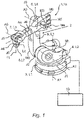
- the 1 shows a robot 1 having a robot arm 2 and a robot controller 10 .
- the robot arm 2 comprises a plurality of links L1 to L7 which are arranged one after the other and are rotatably connected to one another by means of joints J1 to J6.
- the robot controller 10 of the robot 1 is designed or set up to execute a robot program by means of which the joints J1 to J6 of the robot arm 2 can be automatically adjusted or rotated according to the robot program or in a manual operation mode.
- the robot controller 10 is connected to controllable electric motors M1 to M6, which are designed to adjust the joints J1 to J6 of the robot 1.
- the links L1 to L7 are a frame 3 and a carousel 4 rotatably mounted relative to the frame 3 about a vertical axis A1.
- Further links of the robot arm 2 are a rocker 5, an arm extension 6 and a preferably multi-axis robot hand 7 with a fastening device designed as a tool flange 8 for fastening a gripper 11 according to the invention pivoted about a preferably horizontal axis of rotation A2.
- the arm extension 6 is in turn pivotably mounted on the first joint J3 of the rocker 5 about a likewise preferably horizontal axis A3.
- This end carries the robot hand 7 with its preferably three axes of rotation A4, A5, A6.
- the joints J1 to J6 can each be driven in a program-controlled manner by one of the electric motors M1 to M6 via the robot controller 10 .
- a gear can be provided between each of the links L1 to L7 and the respective associated electric motors M1 to M6.
- link L7 is designed as a tool flange for attaching a gripper 11 according to the invention.
- the 2 shows a robot 1 in an exemplary embodiment as a so-called lightweight robot 1b, which has a robot arm 2 and a robot controller 10b.
- the robot arm 2 comprises eight links L1-L8 which are arranged one after the other and are rotatably connected to one another by means of joints J1-J7.
- link L8 is designed as a tool flange for attaching a gripper 11 according to the invention.
- the 3 shows a robot 1 in an exemplary embodiment as a so-called SCARA robot 1c, which has a robot arm 2 and a robot controller 10c.
- the robot arm 2 comprises five links L1-L5 which are arranged one after the other and are rotatably connected to one another by means of joints J1-J4.
- link L5 is designed as a tool flange for attaching a gripper 11 according to the invention.
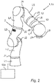
- the gripper 11 has a gripper base body 12 which includes a connecting flange 13 which is designed to fasten the gripper 11 to the tool flange 8 of the robot arm 2 .
- the gripper 11 also has a base member 14 which can be pivoted by means of a first pivot joint 15.1 ( 6 ) is rotatably mounted on the gripper body 12 about a first axis of rotation D1.
- the gripper 11 also has a first gripper finger 16.1, which by means of a second rotary joint 15.2 is rotatably mounted with respect to the base member 14 about a second axis of rotation D2, which is aligned parallel to the first axis of rotation D1.
- the gripper 11 also has at least one second gripper finger 16.2, 16.3.
- the gripper 11 has a finger carrier 17 to which the first gripper finger 16.1 is attached.
- the finger carrier 17 is rotatably mounted on an intermediate member 17a of the gripper 11 by means of a third rotary joint 15.3 about a third axis of rotation D3, which is aligned parallel to both the first axis of rotation D1 and the second axis of rotation D2.
- the intermediate member 17a is in turn mounted on the base member 14 so as to be rotatable about the second axis of rotation D2 by means of the second rotary joint 15.2.
- the links of the gripper 11, which are formed by the gripper body 12, the base member 14, the intermediate member 17a and the finger carrier 17, form a kinematic chain of links through the first pivot joint 15.1, the second pivot joint 15.2 and the third Swivel joint 15.3 can be adjusted in a rotatable manner, as explained in more detail below.
- the three axes of rotation D1, D2 and D3 of the first pivot joint 15.1, the second pivot joint 15.2 and the third pivot joint 15.3 are aligned parallel to one another.
- the first gripper finger 16.1 mounted on the finger carrier 17 can be moved towards or away from the stationary second gripper finger 16.2 or the third gripper finger 16.3 in the plane of the second end face of the gripper body 12.
- the first gripper finger 16.1 can be positioned on any path and in any orientation on the plane of the second end face of the gripper body proceed, provided that that the movement of each of the three rotary axes can be controlled independently of the others.
- the base member 14 has a rotationally symmetrical outer casing wall, on which the base member 14 is rotatably mounted completely within the outer contour of the gripper body 12 .
- the intermediate member 17a of the gripper 11 has a rotationally symmetrical outer casing wall, on which the intermediate member 17a is mounted so that it can rotate completely within the outer contour of the base member 14 .
- the finger carrier 17 of the gripper 11 has a rotationally symmetrical outer casing wall, on which the finger carrier 17 is rotatably mounted completely within the outer contour of the intermediate member 17a.
- the gripper 11 has the gripper base body 12, the base member 14, which is mounted by means of the first rotary joint 15.1 so that it can rotate about a first axis of rotation D1 (extending perpendicularly out of the plane of the drawing) with respect to the gripper base body 12, and the intermediate member 17a, which is mounted by means of the second Swivel joint 15.2 is rotatably mounted with respect to the base member 14, namely about a second axis of rotation D2 (extending perpendicularly out of the plane of the drawing) which is aligned parallel to the first axis of rotation D1 and is arranged at a constant first distance A1 from the first axis of rotation D1.
- the gripper 11 also has a finger carrier 17, which carries the first gripper finger 16.1 and which is rotatably mounted by means of a third pivot joint 15.3 with respect to the intermediate member 17a, specifically about a third axis of rotation D3 (extending perpendicularly out of the plane of the drawing) which is parallel to both aligned to the first axis of rotation as well as to the second axis of rotation and is arranged at a constant second distance A2 from the second axis of rotation D2, which second distance A2 has the same length as the first distance A1.
- the gripper 11 can have a single drive motor, which is designed to adjust the first gripper finger 16.1 relative to the gripper body 12 on a straight path without changing the orientation of the first gripper finger 16.1.
- the gripper 11 shown has a gripper base body 12, at least one first gripper finger 16.1 and at least one second gripper finger 16.2, 16.3, as well as a gear 21 which is designed so that the at least one first gripper finger 16.1 and the at least one second gripper finger 16.2 can be adjusted relative to one another on the gripper base body 12 to store.
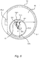
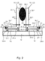
- the joint guide 23 is designed as a parallelogram guide 23a.
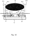
- the parallelogram guide 23a comprises four swivel joints 26.1, 26.2, 26.3, 26.4, these can also be solid joints that do not have a clear pivot point, of which two swivel joints 26.1, 26.2, which are arranged at a first distance A1 from one another, on the second leg 22.2 are formed and two rotary joints 26.3, 26.4, which are arranged at a second distance A2 from one another, which is the same length as the first distance A1, are formed on the finder base body 18, and two coupling rods 27.1, 27.2 are provided, of which each coupling rod 27.1 , 27.2 connects one of the pivot joints of the second leg 26.1, 26.2 to one of the pivot joints 26.3, 26.4 of the finder body 18, wherein the coupling rods 27.1, 27.2 each have the same effective lengths L1, L2, which are smaller than the first distance A1 and the second Distance A2 ( 10 ).
- the kinematic connection of the lengths between the flexure joints can also be given in a one-piece parallelogram. However, it can also be different, for example in such a way that only the deformations under the action of force are designed in such a way that the first leg deforms parallel to the second leg.
- the force-measuring device 24 is arranged between an end face 28 of the second leg 22.2 opposite the first leg 22.1 and a support surface 29 of the finger base body 18.
- the second leg 22.2 can accordingly have a longitudinal extension with a first end face and a second end face.
- the first leg 22.1 can be arranged on the first end face and can extend away from the second leg 22.2 at a right angle.
- the force-measuring device 24 is supported on the second end face, which is opposite the first end face.
- the force measuring device 24 is supported on the support surface 29 of the finger base body 18 .
- the support surface 29 can be formed by a side wall of a projection 30 which projects laterally to the longitudinal extent of the second leg 22.2.
- the two coupling rods 27.1, 27.2 are arranged in the force measuring direction between the force measuring device 24 and the second gripping surface 25.2.
- the force-measuring device 24 is thus located on a side of the parallelogram guide 23a opposite the first gripping surface 25.1 and the second gripping surface 25.2.
- the force-measuring device 24 can be supported on the one hand on the second end face 28 of the second leg 22.2, which is opposite the first end face.
- the force-measuring device 24 can be supported on the support surface 29 of the finger base body 18 .
- the support surface 29 can be formed by a side wall of the projection 30, which projects laterally to the longitudinal extent of the second leg 22.2.
- the force measuring device 24 is both fixed to the second end face 28 of the second leg 22.2, as well as fixed to the support surface 29, in particular with connected to the side wall of the projection 30 of the finger base body 18, so that not only compressive forces but also tensile forces between the second leg 22.2 and the finger base body 18 can be measured.
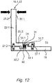
- the second leg 22.2 has a first groove 31 with two opposite leg groove walls 31.1, 31.2 and the finger base body 18 has a second groove 32 with two opposite base body groove walls 32.1, 32.2, one of the leg groove walls 31.1 being arranged opposite one of the base body groove walls 32.1, forming a receiving space 33 and the force-measuring device 24 is arranged in the receiving space 33 .
- the first groove 31 of the second leg 22.2 is opposite the second groove 32 of the finger base body 18, so that the two grooves 31, 32 delimit the receiving space 33.
- the formation of a receiving space 33 allows the force-measuring device 24 to be integrated in a space-saving manner in the gripper finger 16.1 between the second leg 22.2 and the finger base body 18.
- the force measuring device 24 is both firmly connected to the leg groove wall 31.1 of the second leg 22.2 and also firmly connected to the base body groove wall 32.1 of the finger base body 18, so that not only compressive forces but also tensile forces between the second leg 22.2 and the finger base body 18 can be measured .
- the force-measuring device 24 is arranged between the two coupling rods 27.1, 27.2 in the force-measuring direction, but can also be arranged at an angle, for example 90°, thereto.
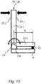
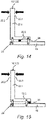
- the joint guide 23 has a pivot bearing 23b, which pivotally mounts the gripping member 22 on the finger base body 18, with the force measuring device 24 being arranged between the finger base body 18 and the second leg 22.2, which is pivotably mounted on the finger base body 18 by the pivot bearing 23b, in order to to measure the gripping force acting on the first leg 22.1, which can be a tensile force or a compressive force.
- the force measuring device 24 is designed to measure shear forces.
- the force-measuring device 24 is arranged inside the parallelogram guide (articulated guide 23). Due to tensile or compressive forces that act on the parallelogram guide (joint guide 23), for example due to an inside handle or an outside handle, which introduces external compressive forces (arrows) into the gripping member 22 either on the first gripping surface 25.1 or on the second gripping surface 25.2 in the arrangement shown 14 Shear forces on the force measuring device 24 a.
- the force measuring device 24 is designed to measure shear forces.
- the force-measuring device 24 is arranged outside of the parallelogram guide (articulated guide 23). Due to tensile or compressive forces that act on the parallelogram guide (joint guide 23), for example due to an inside handle or an outside handle, which introduces external compressive forces (arrows) into the gripping member 22 either on the first gripping surface 25.1 or on the second gripping surface 25.2 in the arrangement shown 14 Shear forces on the force measuring device 24 a.
Landscapes
- Engineering & Computer Science (AREA)
- Human Computer Interaction (AREA)
- Robotics (AREA)
- Mechanical Engineering (AREA)
- Manipulator (AREA)
Claims (8)
- Dispositif de préhension, présentant un corps de base de dispositif de préhension (12), au moins un premier doigt de dispositif de préhension (16.1) et au moins un deuxième doigt de dispositif de préhension (16.2, 16.3), ainsi qu'une transmission (21) qui est réalisée pour supporter l'au moins un premier doigt de dispositif de préhension (16.1) et l'au moins un deuxième doigt de dispositif de préhension (16.2) de manière déplaçable l'un par rapport à l'autre sur le corps de base de dispositif de préhension (12),au moins l'un des premiers et deuxièmes doigts de dispositif de préhension (16.1, 16.2, 16.3) présentant :- un corps de base de doigt (18) disposé sur le corps de base de dispositif de préhension (12),- un organe de préhension (22) comprenant une première branche (22.1) et une deuxième branche (22.2) qui est disposée de manière orientée suivant un angle fixe par rapport à la première branche (22.1) et est reliée rigidement à la première branche (22.1),- au moins un guide d'articulation (23) qui est réalisé pour supporter la deuxième branche (22.2) sur le corps de base de doigt (18) de manière déplaçable,- un dispositif de mesure de force (24) qui est réalisé pour mesurer à la fois des forces dans un premier sens, et des forces dans un deuxième sens opposé,- la première branche (22.1) présentant, sur une première surface, une première face de préhension (25.1) et, sur une deuxième surface opposée à la première surface, une deuxième face de préhension (25.2), etle dispositif de mesure de force (24) étant disposé entre la deuxième branche (22.2) et le corps de base de doigt (18) et étant conçu pour mesurer une force de préhension agissant sur la première face de préhension (25.1) de la première branche (22.1) et une force de préhension agissant sur la deuxième face de préhension (25.2) de la première branche (22.1), caractérisé en ce quele guide d'articulation (23) présente un palier de rotation (23b), lequel supporte l'organe de préhension (22) de manière pivotante sur le corps de base de doigt (18) et le dispositif de mesure de force (24) est disposé entre le corps de base de doigt (18) et la deuxième branche (22.2), qui est supportée de manière pivotante sur le corps de base de doigt (18) par le biais du palier de rotation (23b), afin de mesurer une force de préhension agissant sur la première branche (22.1), laquelle force de préhension peut être une force de traction ou une force de compression.
- Dispositif de préhension selon la revendication 1, caractérisé en ce que le guide d'articulation (23) est un guide à parallélogramme.
- Dispositif de préhension selon la revendication 2, caractérisé en ce que le guide à parallélogramme comporte quatre articulations rotatives (26.1, 26.2, 26.3, 26.4), parmi lesquelles deux articulations rotatives (26.1, 26.2), qui sont disposées à une première distance (A1) l'une de l'autre, sont réalisées sur la deuxième branche (22.2) et deux articulations rotatives (26.3, 26.4), qui sont disposées à une deuxième distance (A2) l'une de l'autre, laquelle est de même longueur que la première distance (A1), sont réalisées sur le corps de base de doigt (18), et deux tiges d'accouplement (27.1, 27.2) sont prévues, parmi lesquelles chaque tige d'accouplement (27.1, 27.2) relie respectivement l'une des articulations rotatives (26.1, 26.2) de la deuxième branche (22.2) à l'une des articulations rotatives (26.3, 26.4) du corps de base de doigt (18), en particulier les tiges d'accouplement (27.1, 27.2) présentant des longueurs (L1, L2) effectives respectivement de même longueur, qui sont inférieures à la première distance (A1) et à la deuxième distance (A2).
- Dispositif de préhension selon l'une des revendications 1 à 3, caractérisé en ce que le dispositif de mesure de force (24) est disposé entre un côté frontal (28), opposé à la première branche (22.1), de la deuxième branche (22.2) et une face d'appui (29) du corps de base de doigt (18).
- Dispositif de préhension selon l'une des revendications 1 à 4, caractérisé en ce que la deuxième branche (22.2) présente une première rainure (31) comprenant deux parois de rainure de branche (31.1, 31.2) en regard et le corps de base de doigt (18) présente une deuxième rainure (32) comprenant deux parois de rainure de corps de base (32.1, 32.2) en regard, l'une des parois de rainure de branche (31.1, 31.2) étant disposée en regard de l'une des parois de rainure de corps de base (32.1, 32.2) en formant un espace de réception (33) et le dispositif de mesure de force (24) étant disposé dans l'espace de réception (33).
- Dispositif de préhension selon l'une des revendications 2 à 5, caractérisé en ce que le dispositif de mesure de force (24) est disposé entre les deux tiges d'accouplement (27.1, 27.2) dans le sens de mesure de force.
- Dispositif de préhension selon l'une des revendications 1 à 6, caractérisé en ce que le dispositif de mesure de force (24) est réalisé pour la mesure de forces de cisaillement.
- Dispositif de préhension selon l'une des revendications 2 à 7, caractérisé en ce que les deux tiges d'accouplement (27.1, 27.2) sont disposées entre le dispositif de mesure de force (24) et la première face de préhension (25.1) et/ou la deuxième face de préhension (25.2) .
Applications Claiming Priority (2)
| Application Number | Priority Date | Filing Date | Title |
|---|---|---|---|
| DE102016200492.1A DE102016200492A1 (de) | 2016-01-15 | 2016-01-15 | Greifer mit einer Kraftmessvorrichtung |
| PCT/EP2017/050609 WO2017121827A1 (fr) | 2016-01-15 | 2017-01-12 | Dispositif de préhension comprenant un dispositif de mesure de force |
Publications (2)
| Publication Number | Publication Date |
|---|---|
| EP3402634A1 EP3402634A1 (fr) | 2018-11-21 |
| EP3402634B1 true EP3402634B1 (fr) | 2022-10-05 |
Family
ID=57796364
Family Applications (1)
| Application Number | Title | Priority Date | Filing Date |
|---|---|---|---|
| EP17700349.8A Active EP3402634B1 (fr) | 2016-01-15 | 2017-01-12 | Dispositif de préhension comprenant un dispositif de mesure de force |
Country Status (3)
| Country | Link |
|---|---|
| EP (1) | EP3402634B1 (fr) |
| DE (1) | DE102016200492A1 (fr) |
| WO (1) | WO2017121827A1 (fr) |
Families Citing this family (9)
| Publication number | Priority date | Publication date | Assignee | Title |
|---|---|---|---|---|
| DE102017218620B4 (de) | 2017-10-18 | 2019-07-04 | Kuka Aktiengesellschaft | Greiferfinger mit einer Kraftmessvorrichtung und Greifer |
| DE102019107848B4 (de) * | 2019-03-27 | 2022-06-15 | Franka Emika Gmbh | Robotergreifer und Verfahren zum Betrieb eines Robotergreifers |
| DE102020110692A1 (de) | 2020-04-20 | 2021-10-21 | Schunk Gmbh & Co. Kg Spann- Und Greiftechnik | Modularer Greiffinger, Greifvorrichtung und Baukasten |
| CN113892848B (zh) * | 2021-10-08 | 2022-10-14 | 杭州景吾智能科技有限公司 | 可翻转物体的翻转跟随轨迹规划方法、装置及系统 |
| US12358164B2 (en) * | 2021-10-19 | 2025-07-15 | Shanghai Flexiv Robotics Technology Co., Ltd. | Gripper and robot having the same |
| CN114080999B (zh) * | 2021-11-06 | 2023-02-28 | 天津市广源畜禽养殖有限公司 | 一种鸡蛋智能化筛选分装系统 |
| CN114770587A (zh) * | 2022-04-26 | 2022-07-22 | 黑龙江东方学院 | 一种三爪式空间抓取快递箱装置及其控制方法 |
| CN115122385A (zh) * | 2022-07-29 | 2022-09-30 | 杭州凯达电力建设有限公司 | 一种机械臂及其夹持器 |
| CN120831196A (zh) * | 2025-09-17 | 2025-10-24 | 歌尔股份有限公司 | 头模组件的调整机构和夹持力测量装置 |
Citations (1)
| Publication number | Priority date | Publication date | Assignee | Title |
|---|---|---|---|---|
| US4579380A (en) * | 1983-12-06 | 1986-04-01 | Carnegie-Mellon University | Servo robot gripper |
Family Cites Families (8)
| Publication number | Priority date | Publication date | Assignee | Title |
|---|---|---|---|---|
| US3948093A (en) * | 1975-06-30 | 1976-04-06 | International Business Machines Corporation | Six degree of freedom force transducer for a manipulator system |
| DE2636473C3 (de) * | 1976-08-13 | 1980-04-10 | Maschinenfabrik Augsburg-Nuernberg Ag, 8000 Muenchen | Greifer, insbesondere für Handhabungsgeräte |
| DE10138684C2 (de) * | 2001-08-07 | 2003-07-03 | Schunk Gmbh & Co Kg | Greif- oder Spannvorrichtung |
| DE102007002624B4 (de) | 2007-01-12 | 2008-11-13 | Inos Automationssoftware Gmbh | Verfahren und Vorrichtung zur Qualitätskontrolle eines rotationssymmetrischen Körpers und Greifer eines Handhabungssystems zum Greifen eines rotationssymmetrischen Körpers |
| JP2008221345A (ja) * | 2007-03-08 | 2008-09-25 | Toyota Industries Corp | ロボットハンド |
| FR2917660B1 (fr) * | 2007-06-25 | 2009-09-25 | Commissariat Energie Atomique | Pince pour robot manipulateur a precision de serrage amelioree et robot manipulateur comportant au moins une telle pince. |
| ES2536645T3 (es) | 2012-05-02 | 2015-05-27 | Glp Systems Gmbh | Mano mecánica |
| JP5543539B2 (ja) * | 2012-07-25 | 2014-07-09 | ファナック株式会社 | 力制御電動ハンド |
-
2016
- 2016-01-15 DE DE102016200492.1A patent/DE102016200492A1/de not_active Ceased
-
2017
- 2017-01-12 WO PCT/EP2017/050609 patent/WO2017121827A1/fr not_active Ceased
- 2017-01-12 EP EP17700349.8A patent/EP3402634B1/fr active Active
Patent Citations (1)
| Publication number | Priority date | Publication date | Assignee | Title |
|---|---|---|---|---|
| US4579380A (en) * | 1983-12-06 | 1986-04-01 | Carnegie-Mellon University | Servo robot gripper |
Also Published As
| Publication number | Publication date |
|---|---|
| WO2017121827A1 (fr) | 2017-07-20 |
| DE102016200492A1 (de) | 2017-07-20 |
| EP3402634A1 (fr) | 2018-11-21 |
Similar Documents
| Publication | Publication Date | Title |
|---|---|---|
| EP3402634B1 (fr) | Dispositif de préhension comprenant un dispositif de mesure de force | |
| EP3341164B1 (fr) | Préhenseur de robot | |
| EP3402635B1 (fr) | Dispositif de préhension comprenant au moins un doigt de préhension adaptatif | |
| DE102010045525B4 (de) | Handgelenk eines geschickten humanoiden Roboters | |
| EP3328598B1 (fr) | Robot équipé d'un dispositif de mesure de force | |
| EP2862677B1 (fr) | Procédé de manipulation d'objets au moyen d'au moins deux robots industriels | |
| EP3641993B1 (fr) | Système de préhension comprenant un capteur sur un palier d'élément de transmission du système de préhension | |
| EP2397279A1 (fr) | Bras robot articulé avec entraînement motorisé du bras | |
| WO2021130282A1 (fr) | Dispositif de préhension, robot et procédé de commande | |
| EP3455036B1 (fr) | Préhenseur de robot pourvu d'un dispositif d'entraînement | |
| DE112020001748T5 (de) | Haltevorrichtung und hiermit versehener roboter | |
| EP4161740A1 (fr) | Pince munie d'un corps de base | |
| EP3826812B1 (fr) | Procédé et système de commande pour étalonner un dispositif de manipulation | |
| EP2653415B1 (fr) | Dispositif de saisie destiné à saisir des objets | |
| WO2015135917A2 (fr) | Procédé pour faire fonctionner un robot et robot correspondant équipé d'un dispositif palpeur mécanique | |
| EP2104636A1 (fr) | Manipulateur | |
| DE102016218180A1 (de) | Assistenzgerät mit erweiterter Reichweite zum Durchführen von Montageaufgaben | |
| EP3341165B1 (fr) | Préhenseur de robot | |
| DE102019201169B4 (de) | Robotergreifer mit einem Kraftsensor | |
| DE102018220567A1 (de) | Handhabungseinrichtung und Roboterarm |
Legal Events
| Date | Code | Title | Description |
|---|---|---|---|
| STAA | Information on the status of an ep patent application or granted ep patent |
Free format text: STATUS: UNKNOWN |
|
| STAA | Information on the status of an ep patent application or granted ep patent |
Free format text: STATUS: THE INTERNATIONAL PUBLICATION HAS BEEN MADE |
|
| PUAI | Public reference made under article 153(3) epc to a published international application that has entered the european phase |
Free format text: ORIGINAL CODE: 0009012 |
|
| STAA | Information on the status of an ep patent application or granted ep patent |
Free format text: STATUS: REQUEST FOR EXAMINATION WAS MADE |
|
| 17P | Request for examination filed |
Effective date: 20180802 |
|
| AK | Designated contracting states |
Kind code of ref document: A1 Designated state(s): AL AT BE BG CH CY CZ DE DK EE ES FI FR GB GR HR HU IE IS IT LI LT LU LV MC MK MT NL NO PL PT RO RS SE SI SK SM TR |
|
| AX | Request for extension of the european patent |
Extension state: BA ME |
|
| DAV | Request for validation of the european patent (deleted) | ||
| DAX | Request for extension of the european patent (deleted) | ||
| GRAP | Despatch of communication of intention to grant a patent |
Free format text: ORIGINAL CODE: EPIDOSNIGR1 |
|
| STAA | Information on the status of an ep patent application or granted ep patent |
Free format text: STATUS: GRANT OF PATENT IS INTENDED |
|
| INTG | Intention to grant announced |
Effective date: 20220428 |
|
| GRAS | Grant fee paid |
Free format text: ORIGINAL CODE: EPIDOSNIGR3 |
|
| GRAA | (expected) grant |
Free format text: ORIGINAL CODE: 0009210 |
|
| STAA | Information on the status of an ep patent application or granted ep patent |
Free format text: STATUS: THE PATENT HAS BEEN GRANTED |
|
| AK | Designated contracting states |
Kind code of ref document: B1 Designated state(s): AL AT BE BG CH CY CZ DE DK EE ES FI FR GB GR HR HU IE IS IT LI LT LU LV MC MK MT NL NO PL PT RO RS SE SI SK SM TR |
|
| REG | Reference to a national code |
Ref country code: GB Ref legal event code: FG4D Free format text: NOT ENGLISH |
|
| REG | Reference to a national code |
Ref country code: CH Ref legal event code: EP |
|
| REG | Reference to a national code |
Ref country code: AT Ref legal event code: REF Ref document number: 1522470 Country of ref document: AT Kind code of ref document: T Effective date: 20221015 |
|
| REG | Reference to a national code |
Ref country code: IE Ref legal event code: FG4D Free format text: LANGUAGE OF EP DOCUMENT: GERMAN |
|
| REG | Reference to a national code |
Ref country code: DE Ref legal event code: R096 Ref document number: 502017013896 Country of ref document: DE |
|
| REG | Reference to a national code |
Ref country code: LT Ref legal event code: MG9D |
|
| REG | Reference to a national code |
Ref country code: NL Ref legal event code: MP Effective date: 20221005 |
|
| PG25 | Lapsed in a contracting state [announced via postgrant information from national office to epo] |
Ref country code: NL Free format text: LAPSE BECAUSE OF FAILURE TO SUBMIT A TRANSLATION OF THE DESCRIPTION OR TO PAY THE FEE WITHIN THE PRESCRIBED TIME-LIMIT Effective date: 20221005 |
|
| PG25 | Lapsed in a contracting state [announced via postgrant information from national office to epo] |
Ref country code: SE Free format text: LAPSE BECAUSE OF FAILURE TO SUBMIT A TRANSLATION OF THE DESCRIPTION OR TO PAY THE FEE WITHIN THE PRESCRIBED TIME-LIMIT Effective date: 20221005 Ref country code: PT Free format text: LAPSE BECAUSE OF FAILURE TO SUBMIT A TRANSLATION OF THE DESCRIPTION OR TO PAY THE FEE WITHIN THE PRESCRIBED TIME-LIMIT Effective date: 20230206 Ref country code: NO Free format text: LAPSE BECAUSE OF FAILURE TO SUBMIT A TRANSLATION OF THE DESCRIPTION OR TO PAY THE FEE WITHIN THE PRESCRIBED TIME-LIMIT Effective date: 20230105 Ref country code: LT Free format text: LAPSE BECAUSE OF FAILURE TO SUBMIT A TRANSLATION OF THE DESCRIPTION OR TO PAY THE FEE WITHIN THE PRESCRIBED TIME-LIMIT Effective date: 20221005 Ref country code: FI Free format text: LAPSE BECAUSE OF FAILURE TO SUBMIT A TRANSLATION OF THE DESCRIPTION OR TO PAY THE FEE WITHIN THE PRESCRIBED TIME-LIMIT Effective date: 20221005 Ref country code: ES Free format text: LAPSE BECAUSE OF FAILURE TO SUBMIT A TRANSLATION OF THE DESCRIPTION OR TO PAY THE FEE WITHIN THE PRESCRIBED TIME-LIMIT Effective date: 20221005 |
|
| PG25 | Lapsed in a contracting state [announced via postgrant information from national office to epo] |
Ref country code: RS Free format text: LAPSE BECAUSE OF FAILURE TO SUBMIT A TRANSLATION OF THE DESCRIPTION OR TO PAY THE FEE WITHIN THE PRESCRIBED TIME-LIMIT Effective date: 20221005 Ref country code: PL Free format text: LAPSE BECAUSE OF FAILURE TO SUBMIT A TRANSLATION OF THE DESCRIPTION OR TO PAY THE FEE WITHIN THE PRESCRIBED TIME-LIMIT Effective date: 20221005 Ref country code: LV Free format text: LAPSE BECAUSE OF FAILURE TO SUBMIT A TRANSLATION OF THE DESCRIPTION OR TO PAY THE FEE WITHIN THE PRESCRIBED TIME-LIMIT Effective date: 20221005 Ref country code: IS Free format text: LAPSE BECAUSE OF FAILURE TO SUBMIT A TRANSLATION OF THE DESCRIPTION OR TO PAY THE FEE WITHIN THE PRESCRIBED TIME-LIMIT Effective date: 20230205 Ref country code: HR Free format text: LAPSE BECAUSE OF FAILURE TO SUBMIT A TRANSLATION OF THE DESCRIPTION OR TO PAY THE FEE WITHIN THE PRESCRIBED TIME-LIMIT Effective date: 20221005 Ref country code: GR Free format text: LAPSE BECAUSE OF FAILURE TO SUBMIT A TRANSLATION OF THE DESCRIPTION OR TO PAY THE FEE WITHIN THE PRESCRIBED TIME-LIMIT Effective date: 20230106 |
|
| REG | Reference to a national code |
Ref country code: DE Ref legal event code: R097 Ref document number: 502017013896 Country of ref document: DE |
|
| P01 | Opt-out of the competence of the unified patent court (upc) registered |
Effective date: 20230528 |
|
| PG25 | Lapsed in a contracting state [announced via postgrant information from national office to epo] |
Ref country code: SM Free format text: LAPSE BECAUSE OF FAILURE TO SUBMIT A TRANSLATION OF THE DESCRIPTION OR TO PAY THE FEE WITHIN THE PRESCRIBED TIME-LIMIT Effective date: 20221005 Ref country code: RO Free format text: LAPSE BECAUSE OF FAILURE TO SUBMIT A TRANSLATION OF THE DESCRIPTION OR TO PAY THE FEE WITHIN THE PRESCRIBED TIME-LIMIT Effective date: 20221005 Ref country code: EE Free format text: LAPSE BECAUSE OF FAILURE TO SUBMIT A TRANSLATION OF THE DESCRIPTION OR TO PAY THE FEE WITHIN THE PRESCRIBED TIME-LIMIT Effective date: 20221005 Ref country code: DK Free format text: LAPSE BECAUSE OF FAILURE TO SUBMIT A TRANSLATION OF THE DESCRIPTION OR TO PAY THE FEE WITHIN THE PRESCRIBED TIME-LIMIT Effective date: 20221005 Ref country code: CZ Free format text: LAPSE BECAUSE OF FAILURE TO SUBMIT A TRANSLATION OF THE DESCRIPTION OR TO PAY THE FEE WITHIN THE PRESCRIBED TIME-LIMIT Effective date: 20221005 |
|
| PLBE | No opposition filed within time limit |
Free format text: ORIGINAL CODE: 0009261 |
|
| STAA | Information on the status of an ep patent application or granted ep patent |
Free format text: STATUS: NO OPPOSITION FILED WITHIN TIME LIMIT |
|
| PG25 | Lapsed in a contracting state [announced via postgrant information from national office to epo] |
Ref country code: SK Free format text: LAPSE BECAUSE OF FAILURE TO SUBMIT A TRANSLATION OF THE DESCRIPTION OR TO PAY THE FEE WITHIN THE PRESCRIBED TIME-LIMIT Effective date: 20221005 Ref country code: AL Free format text: LAPSE BECAUSE OF FAILURE TO SUBMIT A TRANSLATION OF THE DESCRIPTION OR TO PAY THE FEE WITHIN THE PRESCRIBED TIME-LIMIT Effective date: 20221005 |
|
| REG | Reference to a national code |
Ref country code: CH Ref legal event code: PL |
|
| 26N | No opposition filed |
Effective date: 20230706 |
|
| PG25 | Lapsed in a contracting state [announced via postgrant information from national office to epo] |
Ref country code: LU Free format text: LAPSE BECAUSE OF NON-PAYMENT OF DUE FEES Effective date: 20230112 |
|
| REG | Reference to a national code |
Ref country code: BE Ref legal event code: MM Effective date: 20230131 |
|
| PG25 | Lapsed in a contracting state [announced via postgrant information from national office to epo] |
Ref country code: LI Free format text: LAPSE BECAUSE OF NON-PAYMENT OF DUE FEES Effective date: 20230131 Ref country code: CH Free format text: LAPSE BECAUSE OF NON-PAYMENT OF DUE FEES Effective date: 20230131 |
|
| PG25 | Lapsed in a contracting state [announced via postgrant information from national office to epo] |
Ref country code: SI Free format text: LAPSE BECAUSE OF FAILURE TO SUBMIT A TRANSLATION OF THE DESCRIPTION OR TO PAY THE FEE WITHIN THE PRESCRIBED TIME-LIMIT Effective date: 20221005 Ref country code: BE Free format text: LAPSE BECAUSE OF NON-PAYMENT OF DUE FEES Effective date: 20230131 |
|
| PG25 | Lapsed in a contracting state [announced via postgrant information from national office to epo] |
Ref country code: IE Free format text: LAPSE BECAUSE OF NON-PAYMENT OF DUE FEES Effective date: 20230112 |
|
| REG | Reference to a national code |
Ref country code: AT Ref legal event code: MM01 Ref document number: 1522470 Country of ref document: AT Kind code of ref document: T Effective date: 20230112 |
|
| PG25 | Lapsed in a contracting state [announced via postgrant information from national office to epo] |
Ref country code: AT Free format text: LAPSE BECAUSE OF NON-PAYMENT OF DUE FEES Effective date: 20230112 |
|
| PG25 | Lapsed in a contracting state [announced via postgrant information from national office to epo] |
Ref country code: AT Free format text: LAPSE BECAUSE OF NON-PAYMENT OF DUE FEES Effective date: 20230112 |
|
| PG25 | Lapsed in a contracting state [announced via postgrant information from national office to epo] |
Ref country code: IT Free format text: LAPSE BECAUSE OF FAILURE TO SUBMIT A TRANSLATION OF THE DESCRIPTION OR TO PAY THE FEE WITHIN THE PRESCRIBED TIME-LIMIT Effective date: 20221005 |
|
| PG25 | Lapsed in a contracting state [announced via postgrant information from national office to epo] |
Ref country code: MC Free format text: LAPSE BECAUSE OF FAILURE TO SUBMIT A TRANSLATION OF THE DESCRIPTION OR TO PAY THE FEE WITHIN THE PRESCRIBED TIME-LIMIT Effective date: 20221005 |
|
| PG25 | Lapsed in a contracting state [announced via postgrant information from national office to epo] |
Ref country code: MC Free format text: LAPSE BECAUSE OF FAILURE TO SUBMIT A TRANSLATION OF THE DESCRIPTION OR TO PAY THE FEE WITHIN THE PRESCRIBED TIME-LIMIT Effective date: 20221005 |
|
| PG25 | Lapsed in a contracting state [announced via postgrant information from national office to epo] |
Ref country code: BG Free format text: LAPSE BECAUSE OF FAILURE TO SUBMIT A TRANSLATION OF THE DESCRIPTION OR TO PAY THE FEE WITHIN THE PRESCRIBED TIME-LIMIT Effective date: 20221005 |
|
| PG25 | Lapsed in a contracting state [announced via postgrant information from national office to epo] |
Ref country code: BG Free format text: LAPSE BECAUSE OF FAILURE TO SUBMIT A TRANSLATION OF THE DESCRIPTION OR TO PAY THE FEE WITHIN THE PRESCRIBED TIME-LIMIT Effective date: 20221005 |
|
| PGFP | Annual fee paid to national office [announced via postgrant information from national office to epo] |
Ref country code: GB Payment date: 20241205 Year of fee payment: 9 |
|
| PGFP | Annual fee paid to national office [announced via postgrant information from national office to epo] |
Ref country code: FR Payment date: 20241209 Year of fee payment: 9 |
|
| PGFP | Annual fee paid to national office [announced via postgrant information from national office to epo] |
Ref country code: DE Payment date: 20241203 Year of fee payment: 9 |
|
| PG25 | Lapsed in a contracting state [announced via postgrant information from national office to epo] |
Ref country code: CY Free format text: LAPSE BECAUSE OF FAILURE TO SUBMIT A TRANSLATION OF THE DESCRIPTION OR TO PAY THE FEE WITHIN THE PRESCRIBED TIME-LIMIT; INVALID AB INITIO Effective date: 20170112 |
|
| PG25 | Lapsed in a contracting state [announced via postgrant information from national office to epo] |
Ref country code: HU Free format text: LAPSE BECAUSE OF FAILURE TO SUBMIT A TRANSLATION OF THE DESCRIPTION OR TO PAY THE FEE WITHIN THE PRESCRIBED TIME-LIMIT; INVALID AB INITIO Effective date: 20170112 |
|
| PG25 | Lapsed in a contracting state [announced via postgrant information from national office to epo] |
Ref country code: TR Free format text: LAPSE BECAUSE OF FAILURE TO SUBMIT A TRANSLATION OF THE DESCRIPTION OR TO PAY THE FEE WITHIN THE PRESCRIBED TIME-LIMIT Effective date: 20221005 |