EP3402634B1 - Gripper having a force measurement device - Google Patents
Gripper having a force measurement device Download PDFInfo
- Publication number
- EP3402634B1 EP3402634B1 EP17700349.8A EP17700349A EP3402634B1 EP 3402634 B1 EP3402634 B1 EP 3402634B1 EP 17700349 A EP17700349 A EP 17700349A EP 3402634 B1 EP3402634 B1 EP 3402634B1
- Authority
- EP
- European Patent Office
- Prior art keywords
- gripper
- finger
- force
- limb
- measuring device
- Prior art date
- Legal status (The legal status is an assumption and is not a legal conclusion. Google has not performed a legal analysis and makes no representation as to the accuracy of the status listed.)
- Active
Links
Images


Classifications
-
- B—PERFORMING OPERATIONS; TRANSPORTING
- B25—HAND TOOLS; PORTABLE POWER-DRIVEN TOOLS; MANIPULATORS
- B25J—MANIPULATORS; CHAMBERS PROVIDED WITH MANIPULATION DEVICES
- B25J13/00—Controls for manipulators
- B25J13/08—Controls for manipulators by means of sensing devices, e.g. viewing or touching devices
- B25J13/081—Touching devices, e.g. pressure-sensitive
- B25J13/082—Grasping-force detectors
Definitions
- the invention relates to a gripper having a gripper base body, at least one first gripper finger and at least one second gripper finger, and a gear mechanism designed to mount the at least one first gripper finger and the at least one second gripper finger on the gripper base body so that they can be adjusted relative to one another.
- a device for quality control of a rotationally symmetrical body having a handling system with a gripper for gripping the body and for transporting the body to a working position, and at least one electronic camera for optically scanning the body in the working position, the gripper of the Handling system has gripper fingers with rotationally symmetrical holding elements for holding the body, wherein the holding elements are designed to be rotatable about their axes of rotation.
- the holding elements of the gripper fingers of the gripper are each non-rotatably connected to a gear wheel, with the gearwheels of all gripper fingers of the gripper meshing indirectly via at least one other gearwheel with a central gearwheel of the gripper, and the gripper has a drive mechanism which drives the central gearwheel in a rotational movement.
- a gripper for manipulating, in particular tubular, sample vessels is known, with a gripper base, at least two gripper fingers each having a holding section for grasping a sample vessel and each arranged on the gripper base such that they can rotate about a finger axis of rotation relative to the gripper base, with the holding sections of the gripper fingers each in are arranged acentrically with respect to the associated finger rotation axis, and with a first drive for rotating the gripper fingers, wherein the gripper fingers are coupled to one another in such a way that they are driven by the drive simultaneously and with the same rotational speed and direction in each case, wherein the gripper base is arranged on a base body and is rotatable relative thereto about a base rotation axis that differs from the finger rotation axes, that a second drive is provided for rotating the gripper base relative to the base body and that a control device is provided for controlling the drives in such a way that a movement combination of rotating the gripper fingers relative to the grip
- the DE 10 2013 107701 A1 describes a force-controlled electric hand, wherein a force sensor detects the gripping force depending on the amount of displacement of parallel beams in a direction of an axis line.
- the object of the invention is to create a gripper with an integrated force measuring device, which force measuring device can measure gripping forces on two opposite gripping surfaces of a gripper finger.
- the gripper can have more than two gripper fingers. In order to achieve opening and closing of the gripper, it is in principle sufficient if only a single gripper finger is designed to be movable and at least one further gripper finger can be rigidly fastened to the gripper base body. However, two, more or all of the gripper fingers can also be designed to be movable.
- the transmission can have at least one drive, so that the at least one movable gripper finger can be driven, in particular moved automatically.
- the gripper has at least two gripper fingers.
- the at least two gripper fingers can counteract each other by means of the gearing be adjusted. This can mean that the at least two gripper fingers can be moved towards each other to close the gripper so that an object positioned between the gripper fingers can be gripped from the outside, and that the at least two gripper fingers can be moved away from each other to close the gripper open so that an object can be released again.
- the gripper can also perform an inside grip.
- the gripper fingers move away from each other until they touch the object to be gripped with both gripper fingers on an inside of the object and the object can thus be gripped from the inside.
- the gripper fingers are then moved towards each other again, the object is released again.
- Such an inner grip is expedient, for example, when the object is a tubular body, into whose cavity the at least two gripper fingers are inserted in a state that is moved together, after which the at least two gripper fingers are moved apart, so that the at least two gripper fingers are on an inner casing wall of the tubular body abut and spread there, so that the tubular body is gripped by the gripper.
- the force-measuring device is designed to measure both forces in a first direction and forces in an opposite, second direction
- the force-measuring device can record or measure both tensile forces and compressive forces, for example.
- the force-measuring device can be arranged on the gripper in such a way that these tensile and compressive forces act directly on the force-measuring device.
- a simple force measurement can be carried out with the same arrangement using the gripper both in an outer grip and in an inner grip.
- the finger base body can be arranged on the gripper base body, for example, in that the finger base body is mounted on the gripper base body. Alternatively, the finger body be formed in one piece with the gripper body.
- the finger body forms a support for the gripping member.
- the finger body can be connected to an output side of the gear, so that by driving the gear, the finger body is moved relative to the gripper body and thus the gripping member is adjusted relative to the gripper body.
- the finger body may be coupled to the gearing such that it performs a linear movement to move the gripping member attached to the finger body relative to a second gripping member, whereby at least two opposing gripper fingers can be selectively opened or closed.
- the finger base body can also be coupled to the gearing in such a way that it performs a rotating or pivoting movement. Such a rotating or pivoting movement can be expedient in order to be able to turn the gripper finger so that either the first gripping surface of the gripper finger faces the object or its opposite second gripping surface faces the object.
- the gripping element forms the actual finger of the gripper finger, which protrudes from the gripper body in order to be able to grip an object in the outer grip or in the inner grip.
- the gripping member has the first gripping surface and the second gripping surface.
- Each gripping surface may be characterized in that its surfaces have a predetermined contour.
- a predetermined contour can be adapted to the shape of an object to be gripped.
- the predetermined contour can in particular correspond to the outer contour of the object to be gripped, ie it can be identical to it.
- each gripping surface can also have a special surface finish.
- the surface texture can be adapted in particular to increase a frictional force between the gripping surface and the object, so that an object can be gripped particularly reliably.
- the surface texture can also be adapted to prevent damage to the surfaces of the object.
- the gripping surface can also have kinematics that enable adaptive adjustment to the object being gripped.
- the gripping surface can be provided with a corrugation or a knurled structure, for example to increase friction.
- the gripping surface can consist of an elastic material.
- the gripping member can consist of an elastic material, or alternatively the gripping member can be covered or coated with an elastic material.
- the elastic material can be designed to have a high coefficient of friction in cooperation with the object to be gripped.
- the gripping member can have an L-shaped basic shape. Accordingly, the first leg can be formed together with the second leg as a one-piece component.
- the first leg can have a first longitudinal extension and the second leg can have a second longitudinal extension, it being possible for the two legs to be aligned with their longitudinal extensions preferably at right angles to one another.
- the fixed angle at which the first leg and the second leg are arranged aligned with one another can accordingly be a fixed angle of 90 degrees.
- the joint guide which is designed to adjustably mount the second leg on the main body of the finger, should at least predominantly only be adjustable in that direction allow in which direction a force measurement should take place. Accordingly, the joint guide should be designed to mount the second leg so that it can only be adjusted in the force measurement direction, such that the force measurement device can measure a force acting in the adjustment direction. This means that the joint guide should be designed so that the second leg should be mounted at least largely or even completely rigidly with respect to the finger body in all directions other than the adjustment direction.
- the force-measuring device is in particular a one-dimensional force-measuring device, i.e. the force-measuring device is designed to measure forces in only one spatial direction. However, the force-measuring device is designed to measure both tensile forces and compressive forces in the individually specified spatial direction.
- the force measuring device can have at least one force sensor.
- the force sensor can be, for example, a load cell, a load cell, a piezo force transducer and/or have at least one strain gauge (DMS).
- DMS strain gauge
- the force measurement can also be carried out using an optical reflection principle, in which the light is reflected according to strength and/or position as a function of the acting force.
- the joint guide has a pivot bearing which pivotally mounts the gripping member on the main finger body and the force measuring device is arranged between the main finger body and the second leg, which is pivotably mounted on the main finger body by the pivot bearing, in order to measure a gripping force acting on the first leg, which is a tensile force or can be a compressive force to measure.
- a jaw base ie the second leg
- the jaw On the side opposite the bearing, the jaw is supported on a tension/compression force sensor. Due to the leverage ratio, the distance at which the force acts on the jaw must be known in order to determine the force precisely.
- the jaw rotates in the bearing by an angular amount, depending on the rigidity of the sensor.
- This type of force measurement is therefore ideal for a gripper with a radial infeed movement, since these grippers vary the angular position of the gripper jaws when closing and opening.
- This is a simple measuring principle for the uniaxial measurement of the force on the gripper fingers. Such an arrangement is decoupled from lateral forces. However, the distance from the point at which the force is applied to the pivot bearing must be known and determined. The angular position of the gripping member changes slightly with respect to the finger body.
- the joint guide can be a parallelogram guide.
- the uniaxial force components can be measured exactly in the direction in which the degree of freedom of the parallel kinematics points. Any other gripping forces that may occur are taken up or absorbed by the kinematics of the parallelogram guide.
- the jaw ie the gripping element
- This parallel kinematics can be very stiff, so that lateral forces do not lead to any deformation of the jaw and its suspension (finger body).
- One degree of freedom of the parallel kinematics can be very smooth. However, the one degree of freedom of the parallel kinematics does not have to be smooth-running. It is important in this context that in such an embodiment, by the parallel kinematics shown spring is not dampened if possible.
- the parallel kinematics can certainly have a high spring stiffness, but the stiffness follows a predetermined, unchanging stiffness characteristic with whose specific force/displacement ratio the force measuring device can be calibrated.
- the tension-pressure sensor can be placed anywhere between the jaw and gripper base (finger body), depending on the space available. This type of force measurement is ideal for parallel grippers where the angular position of the jaws does not change when closing and opening.
- the parallelogram guide can comprise four pivots, of which two pivots, which are arranged at a first distance from each other, are formed on the second leg and two pivots, which are arranged at a second distance from each other, which is the same length as the first distance, are formed on the finder body are designed, with two coupling rods being provided, of which each coupling rod connects one of the pivot joints of the second leg to one of the pivot joints of the finder body, with the coupling rods in particular each having the same effective lengths which are smaller than the first distance and the second distance.
- the four-bar linkage formed by the parallelogram linkage accordingly has significantly different aspect ratios.
- the aspect ratio may be 1 to 2, 1 to 3, or greater.
- the force-measuring device can be arranged and aligned in such a way that the force-measuring device is aligned with its force-measuring direction parallel to the longer side of the parallelogram guide.
- the force-measuring device can be arranged between an end face of the second leg opposite the first leg and a support surface of the finger base body.
- the second leg can have a longitudinal extension with a first end face and a second end face.
- the first leg can be arranged on the first end face and can extend away from the second leg at a right angle.
- the force-measuring device is supported on the second end face, which is opposite the first end face.
- the force-measuring device is supported on the support surface of the finger body.
- the support surface can be formed by a side wall of a projection which projects laterally to the longitudinal extent of the second leg.
- the force measuring device is both firmly connected to the second end face of the second leg and also firmly connected to the support surface, in particular to the side wall of the projection of the finger body, so that not only compressive forces but also tensile forces between the second leg and the finger body can be measured .
- the second leg can have a first groove with two opposite leg groove walls and the finger base body can have a second groove with two opposite base body groove walls, one of the leg groove walls being arranged opposite one of the base body groove walls to form a receiving space and the force measuring device being arranged in the receiving space.
- the first groove of the second leg is opposite the second groove of the finger base body, so that the two grooves delimit the receiving space.
- the force-measuring device can be used in a space-saving manner be integrated into the gripper finger between the second leg and the finger body.
- the force measuring device is both firmly connected to one of the leg groove walls of the second leg and also firmly connected to one of the main body groove walls of the finger main body, so that not only compressive forces but also tensile forces between the second leg and the finger main body can be measured.
- the force-measuring device can be arranged between the two coupling rods in the force-measuring direction. Accordingly, the force-measuring device can be arranged within the four-bar linkage formed by the parallelogram linkage. This results in a particularly compact design, in which the force-measuring device is not only integrated in the gripper finger, but the force-measuring device is also integrated in the articulated guide, i.e. the parallelogram guide of the gripper finger.
- the two coupling rods can be arranged between the force-measuring device and the first gripping surface and/or the second gripping surface.
- the force-measuring device is thus located on the side of the parallelogram guide opposite the first gripping surface and/or the second gripping surface.
- the force-measuring device can be supported on the one hand on the second end face of the second leg, which is opposite the first end face.
- the force-measuring device can be supported on a support surface of the finger base body.
- the support surface can be formed by a side wall of a projection which projects laterally to the longitudinal extent of the second leg.
- the force measuring device is fixed to both the connected to the second end face of the second leg, as well as firmly connected to the support surface, in particular to the side wall of the projection of the finger body, so that not only compressive forces but also tensile forces between the second leg and the finger body can be measured.
- the force measuring device can also be fitted between the second leg and the gripper body in such a way that the tensile and compressive forces to be measured are transmitted to the measuring device as shear forces.
- the parallelogram can also be made in one piece.
- the rotary joints are then solid joints.
- the coupling rods are therefore part of the first and second leg and can have external shapes that affect the deformability of the coupling rods when a tensile or compressive force acts on the first leg.
- These flexure joints do not have a clear axis of rotation, but instead deform when force is applied, which results from their shape and material properties.
- the one-piece parallel kinematics is constructed in such a way that it can absorb forces and moments in all directions without being severely deformed and only due to forces acting in the measuring direction or in the opposite direction, a parallel displacement of the first leg with respect to the second leg is experienced.
- Such a one-piece design of the parallelogram has positive properties for the measurement.
- the friction during deformation can be neglected compared to the friction in a bearing if the parallelogram is built up in several parts. Friction during deformation is included in the measurement as an error.
- the functional relationship between the value of the force applied and the value of the deformation can be influenced well by the choice of shape and material and can thus be designed so that this does not change during the service life of the measuring jaws. This means that the measuring body used can be calibrated well and permanently.
- the force-measuring device can be designed to measure shear forces.
- the force-measuring device which is designed to measure shear forces
- Such a shear force measuring device can be designed analogously to the described embodiments to force measuring devices, which is designed to measure tensile and compressive forces, the arrangement then differing only in that the shear force measuring device is decoupled on two surfaces of the gripping members, which are orthogonal aligned with the faces of the gripping members of the force measuring device for measuring tensile and compressive forces.
- first gripping surface of the relevant gripper finger and the opposite second gripping surface of the relevant gripper finger can be selectively used by gripping an object either in an outer grip or in an inner grip.
- first gripping surface of the gripper finger in question and the opposite second gripping surface of the gripper finger in question can also be used by reorienting the gripper finger in question with respect to the gripper body, for example.
- the transmission can be designed, for example, to be able to reorient the at least one of the first and second gripper fingers in such a way relative to the gripper body, so that either the first gripping surface or the second gripping surface can be turned towards an object to be gripped.
- the gripper according to the invention can be designed and/or set up to be moved in space by means of a robot, in particular its robot arm.
- a robot controller of the robot can be set up to move or adjust the at least one gripper finger of the gripper in order to be able to grip and/or release an object.
- An exemplary gripper of a robot which has at least one gripper finger designed according to the invention with a force measuring device.
- the purpose of the transmission described for this purpose is to be able to move three rotary joints in a coordinated manner by means of just one drive motor in such a way that the gripper finger executes a linear movement with respect to the gripper base body.
- the coupling device described a movement path that deviates from a linear movement can also be achieved for the gripper finger.
- the gearing can be designed to enable a reorientation of the gripper finger, in particular a turning of the gripper finger.
- the gripper can optionally also be controlled with more than a single drive motor.
- the gripper can have a base member, which is mounted rotatably about a first axis of rotation with respect to the gripper body by means of a first pivot joint, and an intermediate member, which is mounted rotatably with respect to the base member by means of a second pivot joint, specifically about a second axis of rotation parallel to the first Axis of rotation is aligned and arranged at a constant first distance from the first axis of rotation, further comprising a Finger carrier which carries a first gripper finger and which is mounted by means of a third pivot joint to be rotatable with respect to the intermediate member about a third pivot axis which is aligned parallel to both the first pivot axis and the second pivot axis and is arranged at a constant second distance from the second pivot axis , wherein the gripper has a drive motor which moves the first gripper finger and is designed to move the first gripper finger by simultaneously adjusting the first pivot joint, the second pivot joint and the third pivot joint.
- the gripper has a base member, which is mounted rotatably about a first axis of rotation with respect to the gripper body by means of a first pivot joint, and an intermediate member which is mounted rotatably with respect to the base member by means of a second pivot joint, specifically about a second axis of rotation, which is aligned parallel to the first axis of rotation and is arranged at a constant first distance from the first axis of rotation, further comprising a finger carrier, which carries a first gripper finger and which is rotatably mounted by means of a third pivot joint with respect to the intermediate member, namely about a third axis of rotation aligned parallel to both the first axis of rotation and the second axis of rotation and disposed at a constant second distance from the second axis of rotation, the second distance having the same length as the first distance, the first pivot being coupled by a first coupling device direction is coupled to the second pivot joint in a predetermined first gear ratio of 1
- Robot arms with associated robot controls are working machines that can be equipped with tools for the automatic handling and/or processing of objects and can be programmed in several movement axes, for example with regard to orientation, position and workflow.
- Industrial robots usually have a robot arm with several links connected via joints and programmable robot controllers (control devices) that automatically control or regulate the movement sequences of the robot arm during operation in order to position and move a robot flange of the robot arm in space.
- the links are moved via drive motors, in particular electric drive motors, which are controlled by the robot controller, in particular with respect to the movement axes of the industrial robot, which represent the degrees of freedom of movement of the joints.
- the robot can be, for example, an industrial robot, which in particular can be an articulated-arm robot with rotary axes that follow one another in series, for example six rotary axes.
- the robot can be a SCARA robot, i.e. a horizontal articulated arm robot, which usually has four degrees of freedom or axes, i.e. joints, of which three joints can be rotating joints and one joint can be a sliding joint.
- the robot can also be a so-called lightweight robot, which in particular can have seven axes of rotation following one another in series.
- Lightweight robots initially differ from conventional industrial robots in that they are of a size that is favorable for human-machine cooperation and at the same time have a relatively high load-bearing capacity in relation to their own weight.
- lightweight robots can also be operated with force and/or torque control instead of just position control, which makes human-robot cooperation safer, for example.
- HRC safe human-machine cooperation
- such a safe human-machine cooperation (HRC) can be achieved that, for example, unintentional collisions of the robot arm with people, such as workers and fitters, can either be prevented or at least mitigated in such a way that the people or fitters are not harmed .
- the force measurement in the gripper fingers according to the invention can be used for HRC operation in order to ensure reliable closing and opening of the jaws by monitoring the forces that occur in the process. Forces of the gripper that cancel each other out, such as occur when closing the jaws against an object, are not recognized by the robot via the sensors with which the drive torques of the robot are determined in the respective joints. This can endanger the user.
- the reliable knowledge that there is an object between the jaws, the gripping width of which is known and/or can be measured, and reliable information about the position of the gripping jaws in the gripper and/or reliable information about the position of the gripping jaws relative to the object being gripped can be available It must be ensured that the jaws only close with a force that can pose a danger to people when the gripping jaws are so close to the surface of the object being gripped that the user can no longer move any part of his body between the jaws.
- Such a robot arm or such a lightweight robot preferably has more than six degrees of freedom, so that in this respect an overdetermined system is created, whereby the same point in space can be posed in the same orientation in several, in particular even an infinite number of different poses of the Robotic arm can be reached.
- the lightweight robot can react to external forces in appropriate ways. Torque sensors arranged on the joints can be used for force measurement, which can detect or measure torques and forces in several spatial directions. Alternatively or additionally, the external forces can also be estimated without sensors, for example using the measured motor currents of the drives on the joints of the lightweight robot. For example, indirect force control by modeling the lightweight robot as mechanical resistance (impedance) or direct force control can be used as control concepts.
- a SCARA robot can also have torque sensors arranged on the joints, which can detect or measure torques and forces in several spatial directions.
- the external forces can also be estimated without sensors, for example using the measured motor currents of the drive motors on the joints of the SCARA robot.
- the first pivot, the second pivot, and the third pivot are coupled together in a fixed structural configuration.
- the gripper has only a single degree of freedom.
- the gripper can therefore be opened or closed with just a single drive motor.
- the gripper is opened by moving the first (movable) gripper finger away from the second (fixed) gripper finger.
- the gripper is closed by moving the first (movable) gripper finger towards the second (fixed) gripper finger.
- the first gripper finger is moved by the gripper's single drive motor.
- a more robust and stiffer mechanism can be created through the exemplary coupling of the first pivot joint, second pivot joint and third pivot joint, than would be possible with a linear guide, for example.
- the first pivot joint, the second pivot joint and the third pivot joint can be mounted very rigidly by means of roller bearings in a manner known per se to a person skilled in the art. Overall, very high closing forces can therefore be realized on the gripper.
- the first pivot joint, the second pivot joint and the third pivot joint are coupled to one another in such a way that the finger carrier or the first gripper finger executes a linear movement with respect to the second (fixed) gripper finger.
- the coupling is achieved by constructively defining the distance between the second axis of rotation of the second swivel joint and the first axis of rotation of the first swivel joint, by constructively defining the distance between the third axis of rotation of the third swivel joint and the second axis of rotation of the second swivel joint and the two transmission ratios from the first swivel joint to second pivot and from second pivot to third pivot.
- the first distance from the first axis of rotation to the second axis of rotation must have the same length as the second distance from the second axis of rotation to the third axis of rotation. This means that the first distance must be the same as the second distance.
- the first pivot must rotate through a first coupling device relative to the second pivot at a specified first gear ratio of 1 to minus 2 and the second pivot must rotate through a second coupling device relative to the third pivot at a specified second gear ratio of 2 to minus 1. This alone has the consequence that the first gripper finger is on a straight line with respect to the second gripper finger Web moves without changing the orientation of the first gripper finger with respect to the second gripper finger.
- the gripper can have at least one second gripper finger which is stationary with respect to the gripper body.
- the gripper forms a gripper tongs which has two gripper jaws, i.e. two gripper fingers which can be opened and closed, of which one gripper jaw is formed by the first gripper finger and the other gripper jaw is formed by the second gripper finger becomes.
- the second gripper finger is designed to be stationary with respect to the gripper body, the gripper tongs are opened and closed by the first (movable) gripper finger being moved towards the second (fixed) gripper finger or moved away from the second (fixed) gripper finger. gripper finger is moved away. The first gripper finger is moved by the gripper's single drive motor.
- the gripper body can have a connecting flange, which is designed to fasten the gripper to a tool flange of a robot arm. Even if the gripper can be positioned by other automated devices, it is preferably provided that the gripper is moved in space by a robot arm, with the robot arm being able to be moved automatically by a robot controller, i.e. in particular under program control.
- the gripper can have a single drive motor, which is designed to adjust the first gripper finger in a straight path relative to the gripper body, without the orientation of the first gripper finger changing in the process.
- the drive motor of the gripper When the drive motor of the gripper is activated in a force- and/or torque-controlled manner, the rotary joints of the gripper can be parameterized with regard to their rigidity.
- the drive motor of the gripper can be controlled in a force- and/or torque-controlled manner by means of impedance control or admittance control.
- a gripper controller or a robot controller can be set up to generate a flexibility of the first gripper finger on the gripper that is suitable for safe human-robot cooperation, in particular by means of impedance control or admittance control.
- manual operation can also mean that the first gripper finger on the gripper can also be moved manually by a worker, i.e. the first gripper finger of the gripper can also be adjusted manually.
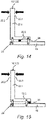
- the 1 shows a robot 1 having a robot arm 2 and a robot controller 10 .
- the robot arm 2 comprises a plurality of links L1 to L7 which are arranged one after the other and are rotatably connected to one another by means of joints J1 to J6.
- the robot controller 10 of the robot 1 is designed or set up to execute a robot program by means of which the joints J1 to J6 of the robot arm 2 can be automatically adjusted or rotated according to the robot program or in a manual operation mode.
- the robot controller 10 is connected to controllable electric motors M1 to M6, which are designed to adjust the joints J1 to J6 of the robot 1.
- the links L1 to L7 are a frame 3 and a carousel 4 rotatably mounted relative to the frame 3 about a vertical axis A1.
- Further links of the robot arm 2 are a rocker 5, an arm extension 6 and a preferably multi-axis robot hand 7 with a fastening device designed as a tool flange 8 for fastening a gripper 11 according to the invention pivoted about a preferably horizontal axis of rotation A2.
- the arm extension 6 is in turn pivotably mounted on the first joint J3 of the rocker 5 about a likewise preferably horizontal axis A3.
- This end carries the robot hand 7 with its preferably three axes of rotation A4, A5, A6.
- the joints J1 to J6 can each be driven in a program-controlled manner by one of the electric motors M1 to M6 via the robot controller 10 .
- a gear can be provided between each of the links L1 to L7 and the respective associated electric motors M1 to M6.
- link L7 is designed as a tool flange for attaching a gripper 11 according to the invention.
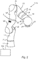
- the 2 shows a robot 1 in an exemplary embodiment as a so-called lightweight robot 1b, which has a robot arm 2 and a robot controller 10b.
- the robot arm 2 comprises eight links L1-L8 which are arranged one after the other and are rotatably connected to one another by means of joints J1-J7.
- link L8 is designed as a tool flange for attaching a gripper 11 according to the invention.
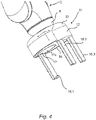
- the 3 shows a robot 1 in an exemplary embodiment as a so-called SCARA robot 1c, which has a robot arm 2 and a robot controller 10c.
- the robot arm 2 comprises five links L1-L5 which are arranged one after the other and are rotatably connected to one another by means of joints J1-J4.
- link L5 is designed as a tool flange for attaching a gripper 11 according to the invention.
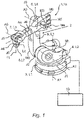
- the gripper 11 has a gripper base body 12 which includes a connecting flange 13 which is designed to fasten the gripper 11 to the tool flange 8 of the robot arm 2 .
- the gripper 11 also has a base member 14 which can be pivoted by means of a first pivot joint 15.1 ( 6 ) is rotatably mounted on the gripper body 12 about a first axis of rotation D1.
- the gripper 11 also has a first gripper finger 16.1, which by means of a second rotary joint 15.2 is rotatably mounted with respect to the base member 14 about a second axis of rotation D2, which is aligned parallel to the first axis of rotation D1.
- the gripper 11 also has at least one second gripper finger 16.2, 16.3.
- the gripper 11 has a finger carrier 17 to which the first gripper finger 16.1 is attached.
- the finger carrier 17 is rotatably mounted on an intermediate member 17a of the gripper 11 by means of a third rotary joint 15.3 about a third axis of rotation D3, which is aligned parallel to both the first axis of rotation D1 and the second axis of rotation D2.
- the intermediate member 17a is in turn mounted on the base member 14 so as to be rotatable about the second axis of rotation D2 by means of the second rotary joint 15.2.
- the links of the gripper 11, which are formed by the gripper body 12, the base member 14, the intermediate member 17a and the finger carrier 17, form a kinematic chain of links through the first pivot joint 15.1, the second pivot joint 15.2 and the third Swivel joint 15.3 can be adjusted in a rotatable manner, as explained in more detail below.
- the three axes of rotation D1, D2 and D3 of the first pivot joint 15.1, the second pivot joint 15.2 and the third pivot joint 15.3 are aligned parallel to one another.
- the first gripper finger 16.1 mounted on the finger carrier 17 can be moved towards or away from the stationary second gripper finger 16.2 or the third gripper finger 16.3 in the plane of the second end face of the gripper body 12.
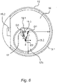
- the first gripper finger 16.1 can be positioned on any path and in any orientation on the plane of the second end face of the gripper body proceed, provided that that the movement of each of the three rotary axes can be controlled independently of the others.
- the base member 14 has a rotationally symmetrical outer casing wall, on which the base member 14 is rotatably mounted completely within the outer contour of the gripper body 12 .
- the intermediate member 17a of the gripper 11 has a rotationally symmetrical outer casing wall, on which the intermediate member 17a is mounted so that it can rotate completely within the outer contour of the base member 14 .
- the finger carrier 17 of the gripper 11 has a rotationally symmetrical outer casing wall, on which the finger carrier 17 is rotatably mounted completely within the outer contour of the intermediate member 17a.
- the gripper 11 has the gripper base body 12, the base member 14, which is mounted by means of the first rotary joint 15.1 so that it can rotate about a first axis of rotation D1 (extending perpendicularly out of the plane of the drawing) with respect to the gripper base body 12, and the intermediate member 17a, which is mounted by means of the second Swivel joint 15.2 is rotatably mounted with respect to the base member 14, namely about a second axis of rotation D2 (extending perpendicularly out of the plane of the drawing) which is aligned parallel to the first axis of rotation D1 and is arranged at a constant first distance A1 from the first axis of rotation D1.
- the gripper 11 also has a finger carrier 17, which carries the first gripper finger 16.1 and which is rotatably mounted by means of a third pivot joint 15.3 with respect to the intermediate member 17a, specifically about a third axis of rotation D3 (extending perpendicularly out of the plane of the drawing) which is parallel to both aligned to the first axis of rotation as well as to the second axis of rotation and is arranged at a constant second distance A2 from the second axis of rotation D2, which second distance A2 has the same length as the first distance A1.
- the gripper 11 can have a single drive motor, which is designed to adjust the first gripper finger 16.1 relative to the gripper body 12 on a straight path without changing the orientation of the first gripper finger 16.1.
- the gripper 11 shown has a gripper base body 12, at least one first gripper finger 16.1 and at least one second gripper finger 16.2, 16.3, as well as a gear 21 which is designed so that the at least one first gripper finger 16.1 and the at least one second gripper finger 16.2 can be adjusted relative to one another on the gripper base body 12 to store.
- the joint guide 23 is designed as a parallelogram guide 23a.
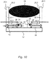
- the parallelogram guide 23a comprises four swivel joints 26.1, 26.2, 26.3, 26.4, these can also be solid joints that do not have a clear pivot point, of which two swivel joints 26.1, 26.2, which are arranged at a first distance A1 from one another, on the second leg 22.2 are formed and two rotary joints 26.3, 26.4, which are arranged at a second distance A2 from one another, which is the same length as the first distance A1, are formed on the finder base body 18, and two coupling rods 27.1, 27.2 are provided, of which each coupling rod 27.1 , 27.2 connects one of the pivot joints of the second leg 26.1, 26.2 to one of the pivot joints 26.3, 26.4 of the finder body 18, wherein the coupling rods 27.1, 27.2 each have the same effective lengths L1, L2, which are smaller than the first distance A1 and the second Distance A2 ( 10 ).
- the kinematic connection of the lengths between the flexure joints can also be given in a one-piece parallelogram. However, it can also be different, for example in such a way that only the deformations under the action of force are designed in such a way that the first leg deforms parallel to the second leg.
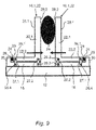
- the force-measuring device 24 is arranged between an end face 28 of the second leg 22.2 opposite the first leg 22.1 and a support surface 29 of the finger base body 18.
- the second leg 22.2 can accordingly have a longitudinal extension with a first end face and a second end face.
- the first leg 22.1 can be arranged on the first end face and can extend away from the second leg 22.2 at a right angle.
- the force-measuring device 24 is supported on the second end face, which is opposite the first end face.
- the force measuring device 24 is supported on the support surface 29 of the finger base body 18 .
- the support surface 29 can be formed by a side wall of a projection 30 which projects laterally to the longitudinal extent of the second leg 22.2.
- the two coupling rods 27.1, 27.2 are arranged in the force measuring direction between the force measuring device 24 and the second gripping surface 25.2.
- the force-measuring device 24 is thus located on a side of the parallelogram guide 23a opposite the first gripping surface 25.1 and the second gripping surface 25.2.
- the force-measuring device 24 can be supported on the one hand on the second end face 28 of the second leg 22.2, which is opposite the first end face.
- the force-measuring device 24 can be supported on the support surface 29 of the finger base body 18 .
- the support surface 29 can be formed by a side wall of the projection 30, which projects laterally to the longitudinal extent of the second leg 22.2.
- the force measuring device 24 is both fixed to the second end face 28 of the second leg 22.2, as well as fixed to the support surface 29, in particular with connected to the side wall of the projection 30 of the finger base body 18, so that not only compressive forces but also tensile forces between the second leg 22.2 and the finger base body 18 can be measured.
- the second leg 22.2 has a first groove 31 with two opposite leg groove walls 31.1, 31.2 and the finger base body 18 has a second groove 32 with two opposite base body groove walls 32.1, 32.2, one of the leg groove walls 31.1 being arranged opposite one of the base body groove walls 32.1, forming a receiving space 33 and the force-measuring device 24 is arranged in the receiving space 33 .
- the first groove 31 of the second leg 22.2 is opposite the second groove 32 of the finger base body 18, so that the two grooves 31, 32 delimit the receiving space 33.
- the formation of a receiving space 33 allows the force-measuring device 24 to be integrated in a space-saving manner in the gripper finger 16.1 between the second leg 22.2 and the finger base body 18.
- the force measuring device 24 is both firmly connected to the leg groove wall 31.1 of the second leg 22.2 and also firmly connected to the base body groove wall 32.1 of the finger base body 18, so that not only compressive forces but also tensile forces between the second leg 22.2 and the finger base body 18 can be measured .
- the force-measuring device 24 is arranged between the two coupling rods 27.1, 27.2 in the force-measuring direction, but can also be arranged at an angle, for example 90°, thereto.
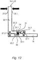
- the joint guide 23 has a pivot bearing 23b, which pivotally mounts the gripping member 22 on the finger base body 18, with the force measuring device 24 being arranged between the finger base body 18 and the second leg 22.2, which is pivotably mounted on the finger base body 18 by the pivot bearing 23b, in order to to measure the gripping force acting on the first leg 22.1, which can be a tensile force or a compressive force.
- the force measuring device 24 is designed to measure shear forces.
- the force-measuring device 24 is arranged inside the parallelogram guide (articulated guide 23). Due to tensile or compressive forces that act on the parallelogram guide (joint guide 23), for example due to an inside handle or an outside handle, which introduces external compressive forces (arrows) into the gripping member 22 either on the first gripping surface 25.1 or on the second gripping surface 25.2 in the arrangement shown 14 Shear forces on the force measuring device 24 a.
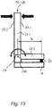
- the force measuring device 24 is designed to measure shear forces.
- the force-measuring device 24 is arranged outside of the parallelogram guide (articulated guide 23). Due to tensile or compressive forces that act on the parallelogram guide (joint guide 23), for example due to an inside handle or an outside handle, which introduces external compressive forces (arrows) into the gripping member 22 either on the first gripping surface 25.1 or on the second gripping surface 25.2 in the arrangement shown 14 Shear forces on the force measuring device 24 a.
Landscapes
- Engineering & Computer Science (AREA)
- Human Computer Interaction (AREA)
- Robotics (AREA)
- Mechanical Engineering (AREA)
- Manipulator (AREA)
Description
Die Erfindung betrifft einen Greifer, aufweisend einen Greifergrundkörper, wenigstens einen ersten Greiferfinger und wenigstens einen zweiten Greiferfinger, sowie ein Getriebe, das ausgebildet ist, den wenigstens einen ersten Greiferfinger und den wenigstens einen zweiten Greiferfinger relativ zueinander verstellbar am Greifergrundkörper zu lagern.The invention relates to a gripper having a gripper base body, at least one first gripper finger and at least one second gripper finger, and a gear mechanism designed to mount the at least one first gripper finger and the at least one second gripper finger on the gripper base body so that they can be adjusted relative to one another.
Aus der
Aus der
Die
Aus der
Aufgabe der Erfindung ist es, einen Greifer mit einer integrierten Kraftmessvorrichtung zu schaffen, welche Kraftmessvorrichtung Greifkräfte an zwei gegenüberliegenden Greifflächen eines Greiferfingers messen kann.The object of the invention is to create a gripper with an integrated force measuring device, which force measuring device can measure gripping forces on two opposite gripping surfaces of a gripper finger.
Diese Aufgabe wird erfindungsgemäß gelöst durch einen Greifer, aufweisend einen Greifergrundkörper, wenigstens einen ersten Greiferfinger und wenigstens einen zweiten Greiferfinger, sowie ein Getriebe, das ausgebildet ist, den wenigstens einen ersten Greiferfinger und den wenigstens einen zweiten Greiferfinger relativ zueinander verstellbar am Greifergrundkörper zu lagern, wobei mindestens einer der ersten und zweiten Greiferfinger aufweist:
- einen am Greifergrundkörper angeordneten Fingergrundkörper,
- ein Greifglied mit einem ersten Schenkel und einem zweiten Schenkel, der in einem festen Winkel zum ersten Schenkel ausgerichtet angeordnet und mit dem ersten Schenkel starr verbunden ist,
- wenigstens eine Gelenkführung, die ausgebildet ist, den zweite Schenkel am Fingergrundkörper verstellbar zu lagern,
- eine Kraftmessvorrichtung, die ausgebildet ist, sowohl Kräfte in einer ersten Richtung, als auch Kräfte in einer entgegengesetzten zweiten Richtung zu messen,
- wobei der erste Schenkel, an einer ersten Oberfläche eine erste Greiffläche und an einer der ersten Oberfläche gegenüberliegenden zweiten Oberfläche eine zweite Greiffläche aufweist, und
- a finger body arranged on the gripper body,
- a gripping member having a first leg and a second leg oriented at a fixed angle to the first leg and rigidly connected to the first leg,
- at least one joint guide, which is designed to adjustably mount the second leg on the finger base body,
- a force measuring device designed to measure both forces in a first direction and forces in an opposite second direction,
- wherein the first leg has a first gripping surface on a first surface and a second gripping surface on a second surface opposite the first surface, and
Der Greifer kann mehr als zwei Greiferfinger aufweisen. Um ein Öffnen und Schließen des Greifers zu erreichen, ist es prinzipiell ausreichend, wenn lediglich ein einziger Greiferfinger beweglich ausgebildet ist und mindestens ein weiterer Greiferfinger dabei starr am Greifergrundkörper befestigt sein kann. Es können jedoch auch zwei, mehr oder alle Greiferfinger beweglich ausgebildet sein. Das Getriebe kann wenigstens einen Antrieb aufweisen, so dass der wenigstens eine bewegliche Greiferfinger angetrieben, insbesondere automatisch bewegt werden kann.The gripper can have more than two gripper fingers. In order to achieve opening and closing of the gripper, it is in principle sufficient if only a single gripper finger is designed to be movable and at least one further gripper finger can be rigidly fastened to the gripper base body. However, two, more or all of the gripper fingers can also be designed to be movable. The transmission can have at least one drive, so that the at least one movable gripper finger can be driven, in particular moved automatically.
Der Greifer weist mindestens zwei Greiferfinger auf. Die mindestens zwei Greiferfinger können mittels des Getriebes gegeneinander verstellt werden. Dies kann bedeuten, dass die mindestens zwei Greiferfinger aufeinander zu bewegt werden können, um den Greifer zu schließen, so dass ein zwischen den Greiferfingern positioniertes Objekt von außen gegriffen werden kann, und dass die mindestens zwei Greiferfinger voneinander weg bewegt werden können, um den Greifer zu öffnen, so dass ein Objekt wieder losgelassen werden kann.The gripper has at least two gripper fingers. The at least two gripper fingers can counteract each other by means of the gearing be adjusted. This can mean that the at least two gripper fingers can be moved towards each other to close the gripper so that an object positioned between the gripper fingers can be gripped from the outside, and that the at least two gripper fingers can be moved away from each other to close the gripper open so that an object can be released again.
Der vorherige Absatz beschreibt einen Außengriff. Der Greifer kann aber auch einen Innengriff ausführen. Dabei bewegen sich die Greiferfinger voneinander weg, bis sie das Greifobjekt mit beiden Greiferfingern auf einer Innenseite des Objekts berühren und das Objekt so von innen gegriffen werden kann. Wenn die Greiferfinger danach wieder aufeinander zu gefahren werden, wird das Objekt wieder losgelassen. Ein solcher Innengriff ist beispielsweise dann zweckmäßig, wenn das Objekt ein rohrförmiger Körper ist, in dessen Hohlraum die wenigstens zwei Greiferfinger in einem zusammengefahrenen Zustand eingeführt werden, danach die wenigstens zwei Greiferfinger auseinandergefahren werden, so dass die wenigstens zwei Greiferfinger an einer Innenmantelwand des rohrförmigen Körper anliegen und sich dort einspreizen, so dass der rohrförmige Körper vom Greifer erfasst ist.The previous paragraph describes an outside handle. However, the gripper can also perform an inside grip. The gripper fingers move away from each other until they touch the object to be gripped with both gripper fingers on an inside of the object and the object can thus be gripped from the inside. When the gripper fingers are then moved towards each other again, the object is released again. Such an inner grip is expedient, for example, when the object is a tubular body, into whose cavity the at least two gripper fingers are inserted in a state that is moved together, after which the at least two gripper fingers are moved apart, so that the at least two gripper fingers are on an inner casing wall of the tubular body abut and spread there, so that the tubular body is gripped by the gripper.
Indem der gattungsgemäße Greifer mindestens einen Greiferfinger aufweist, der:
- einen am Greifergrundkörper angeordneten Fingergrundkörper aufweist,
- ein Greifglied mit einem ersten Schenkel und einem zweiten Schenkel aufweist, der in einem festen Winkel zum ersten Schenkel ausgerichtet angeordnet und mit dem ersten Schenkel starr verbunden ist,
- wenigstens eine Gelenkführung aufweist, die ausgebildet ist, den zweite Schenkel am Fingergrundkörper verstellbar zu lagern,
- eine Kraftmessvorrichtung aufweist, die ausgebildet ist, sowohl Kräfte in einer ersten Richtung, als auch Kräfte in einer entgegengesetzten zweiten Richtung zu messen,
- wobei der erste Schenkel, an einer ersten Oberfläche eine erste Greiffläche und an einer der ersten Oberfläche gegenüberliegenden zweiten Oberfläche eine zweite Greiffläche aufweist, und
- wobei die Kraftmessvorrichtung zwischen dem zweiten Schenkel und dem Fingergrundkörper angeordnet ist und eingerichtet ist, eine auf die erste Greiffläche des ersten Schenkels wirkende Greifkraft und eine auf die zweite Greiffläche des ersten Schenkels wirkende Greifkraft zu messen, wird ein Greifer mit einer integrierten Kraftmessvorrichtung geschaffen, welche Kraftmessvorrichtung Greifkräfte an zwei gegenüberliegenden Greifflächen eines Greiferfingers messen kann. So kann mit derselben integrierten Kraftmessvorrichtung eine Greifkraft sowohl im Falle eines Außengriffes als auch im Falle eines Innengriffes gemessen werden.
- has a finger base body arranged on the gripper base body,
- a gripping member having a first leg and a second leg oriented at a fixed angle to the first leg and rigidly connected to the first leg,
- has at least one joint guide which is designed to adjustably mount the second leg on the finger base body,
- has a force measuring device which is designed to measure both forces in a first direction and forces in an opposite second direction,
- wherein the first leg has a first gripping surface on a first surface and a second gripping surface on a second surface opposite the first surface, and
- wherein the force-measuring device is arranged between the second leg and the finger base body and is set up to measure a gripping force acting on the first gripping surface of the first leg and a gripping force acting on the second gripping surface of the first leg, a gripper with an integrated force-measuring device is created which Force measuring device can measure gripping forces on two opposite gripping surfaces of a gripper finger. With the same integrated force measuring device, a gripping force can be measured both in the case of an outside grip and in the case of an inside grip.
Indem die Kraftmessvorrichtung ausgebildet ist, sowohl Kräfte in einer ersten Richtung, als auch Kräfte in einer entgegengesetzten zweiten Richtung zu messen, können durch die Kraftmessvorrichtung beispielsweise sowohl Zugkräfte, als auch Druckkräfte aufgenommen bzw. gemessen werden. Die Kraftmessvorrichtung kann dabei derart an dem Greifer angeordnet sein, dass diese Zugkräfte und Druckkräfte unmittelbar auf die Kraftmessvorrichtung einwirken. Insbesondere kann dadurch mit derselben Anordnung mittels des Greifers sowohl in einem Außengriff, als auch in einem Innengriff eine einfache Kraftmessung durchgeführt werden.Because the force-measuring device is designed to measure both forces in a first direction and forces in an opposite, second direction, the force-measuring device can record or measure both tensile forces and compressive forces, for example. The force-measuring device can be arranged on the gripper in such a way that these tensile and compressive forces act directly on the force-measuring device. In particular, a simple force measurement can be carried out with the same arrangement using the gripper both in an outer grip and in an inner grip.
Der Fingergrundkörper kann am Greifergrundkörper beispielsweise dadurch angeordnet sein, dass der Fingergrundkörper am Greifergrundkörper gelagert ist. Alternativ kann der Fingergrundkörper einteilig mit dem Greifergrundkörper ausgebildet sein.The finger base body can be arranged on the gripper base body, for example, in that the finger base body is mounted on the gripper base body. Alternatively, the finger body be formed in one piece with the gripper body.
Der Fingergrundkörper bildet einen Träger für das Greifglied. Der Fingergrundkörper kann mit einer Abtriebsseite des Getriebes verbunden sein, so dass durch ein Antreiben des Getriebes der Fingergrundkörper relativ zum Greifergrundkörper bewegt wird und somit auch das Greifglied relativ zum Greifergrundkörper verstellt wird. Der Fingergrundkörper kann derart an das Getriebe angekoppelt sein, so dass er eine lineare Bewegung ausführt, um das am Fingergrundkörper befestigten Greifglied relativ zu einem zweiten Greifglied bewegen zu können, wodurch wenigstens zwei gegenüberliegende Greiferfinger wahlweise geöffnet oder geschlossen werden können. Alternativ oder ergänzend kann der Fingergrundkörper jedoch auch derart an das Getriebe angekoppelt sein, so dass er eine rotierende oder schwenkende Bewegung ausführt. Eine solche rotierende oder schwenkende Bewegung kann zweckmäßig sein, um den Greiferfinger wenden zu können, so dass entweder die erste Greiffläche des Greiferfingers dem Objekt zugewandt ist oder seine gegenüberliegende zweite Greiffläche dem Objekt zugewandt ist.The finger body forms a support for the gripping member. The finger body can be connected to an output side of the gear, so that by driving the gear, the finger body is moved relative to the gripper body and thus the gripping member is adjusted relative to the gripper body. The finger body may be coupled to the gearing such that it performs a linear movement to move the gripping member attached to the finger body relative to a second gripping member, whereby at least two opposing gripper fingers can be selectively opened or closed. Alternatively or additionally, however, the finger base body can also be coupled to the gearing in such a way that it performs a rotating or pivoting movement. Such a rotating or pivoting movement can be expedient in order to be able to turn the gripper finger so that either the first gripping surface of the gripper finger faces the object or its opposite second gripping surface faces the object.
Das Greifglied bildet den eigentlichen Finger des Greiferfingers, der von dem Greifergrundkörper vorspringt, um ein Objekt im Außengriff oder im Innengriff fassen zu können. Demgemäß weist das Greifglied die erste Greiffläche und die zweite Greiffläche auf. Jede Greiffläche kann dadurch gekennzeichnet sein, dass ihre Oberflächen eine vorbestimmte Kontur aufweist. Eine vorbestimmt Kontur kann an die Gestalt eines zu greifenden Objekts angepasst sein. Die vorbestimmt Kontur kann insbesondere der Außenkontur des zu greifenden Objekts entsprechen, d.h. zu dieser identisch sein. Alternativ oder ergänzend zu einer bestimmten Kontur kann jede Greiffläche auch eine spezielle Oberflächenbeschaffenheit aufweisen. Die Oberflächenbeschaffenheit kann insbesondere dazu angepasst sein, um eine Reibkraft zwischen der Greiffläche und dem Objekt zu erhöhen, so dass ein Objekt besonders zuverlässig gegriffen werden kann. Die Oberflächenbeschaffenheit kann aber auch dazu angepasst sein, um Beschädigungen der Oberflächen des Objekts zu verhindern.The gripping element forms the actual finger of the gripper finger, which protrudes from the gripper body in order to be able to grip an object in the outer grip or in the inner grip. Accordingly, the gripping member has the first gripping surface and the second gripping surface. Each gripping surface may be characterized in that its surfaces have a predetermined contour. A predetermined contour can be adapted to the shape of an object to be gripped. The predetermined contour can in particular correspond to the outer contour of the object to be gripped, ie it can be identical to it. As an alternative or in addition to a specific contour, each gripping surface can also have a special surface finish. the The surface texture can be adapted in particular to increase a frictional force between the gripping surface and the object, so that an object can be gripped particularly reliably. However, the surface texture can also be adapted to prevent damage to the surfaces of the object.
Die Greiffläche kann auch eine Kinematik aufweisen, die ein adaptives Anpassen an das Greifobjekt ermöglicht.The gripping surface can also have kinematics that enable adaptive adjustment to the object being gripped.
Generell kann die Greiffläche beispielsweise zur Erhöhung der Reibung mit einer Riffelung oder einer Rändelstruktur versehen sein. Alternativ oder ergänzend kann die Greiffläche aus einem elastischen Material bestehen. Dazu kann entweder das Greifglied aus einem elastischen Material bestehen, oder alternativ kann das Greifglied mit einem elastischen Material bedeckt oder überzogen sein. Das elastische Material kann ausgebildet sein, in Zusammenwirken mit dem zu greifenden Objekt einen hohen Reibungskoeffizienten aufzuweisen.In general, the gripping surface can be provided with a corrugation or a knurled structure, for example to increase friction. Alternatively or additionally, the gripping surface can consist of an elastic material. To this end, either the gripping member can consist of an elastic material, or alternatively the gripping member can be covered or coated with an elastic material. The elastic material can be designed to have a high coefficient of friction in cooperation with the object to be gripped.
Zur Bildung des ersten Schenkels und des zweiten Schenkels kann das Greifglied eine L-förmige Grundform aufweisen. Demgemäß kann der erste Schenkel zusammen mit dem zweiten Schenkel als ein einteiliges Bauteil ausgebildet sein. Der erste Schenkel kann eine erste Längserstreckung aufweisen und der zweite Schenkel kann eine zweite Längserstreckung aufweisen, wobei die beiden Schenkel mit ihren Längserstreckungen vorzugsweise in einem rechten Winkel zueinander ausgerichtet sein können. Der feste Winkel in dem der erste Schenkel und der zweite Schenkel zueinander ausgerichtet angeordnet sind kann demgemäß ein fester Winkel von 90 Grad sein.To form the first leg and the second leg, the gripping member can have an L-shaped basic shape. Accordingly, the first leg can be formed together with the second leg as a one-piece component. The first leg can have a first longitudinal extension and the second leg can have a second longitudinal extension, it being possible for the two legs to be aligned with their longitudinal extensions preferably at right angles to one another. The fixed angle at which the first leg and the second leg are arranged aligned with one another can accordingly be a fixed angle of 90 degrees.
Die Gelenkführung, die ausgebildet ist, den zweiten Schenkel am Fingergrundkörper verstellbar zu lagern, soll zumindest überwiegend nur eine Verstellbarkeit in derjenigen Richtung zulassen, in welcher Richtung eine Kraftmessung stattfinden soll. Die Gelenkführung soll demgemäß ausgebildet sein, den zweiten Schenkel lediglich in Kraftmessrichtung verstellbar zu lagern, derart, dass die Kraftmessvorrichtung eine in Verstellrichtung wirkende Kraft messen kann. Dies bedeutet, dass die Gelenkführung demgemäß ausgebildet sein soll, dass der zweite Schenkel in allen anderen Richtungen als der Verstellrichtung zumindest weitgehend oder sogar völlig starr bezüglich des Fingergrundkörpers gelagert sein soll.The joint guide, which is designed to adjustably mount the second leg on the main body of the finger, should at least predominantly only be adjustable in that direction allow in which direction a force measurement should take place. Accordingly, the joint guide should be designed to mount the second leg so that it can only be adjusted in the force measurement direction, such that the force measurement device can measure a force acting in the adjustment direction. This means that the joint guide should be designed so that the second leg should be mounted at least largely or even completely rigidly with respect to the finger body in all directions other than the adjustment direction.
Die Kraftmessvorrichtung ist insbesondere eine eindimensionale Kraftmessvorrichtung, d.h. die Kraftmessvorrichtung ist ausgebildet Kräfte nur in einer Raumrichtung zu messen. Die Kraftmessvorrichtung ist jedoch ausgebildet sowohl Zugkräfte, als auch Druckkräfte in der einzelnen vorgegebenen Raumrichtung zu messen. Die Kraftmessvorrichtung kann wenigstens einen Kraftsensor aufweisen. Der Kraftsensor kann beispielsweise eine Kraftmessdose, eine Wägezelle, ein Piezokraftaufnehmer sein und/oder wenigstens einen Dehnmessstreifen (DMS) aufweisen. Die Kraftmessung kann aber auch über ein optisches Reflexionsprinzip erfolgen, bei dem das Licht nach Stärke und/oder Position in Abhängigkeit zur angreifenden Kraft reflektiert wird.The force-measuring device is in particular a one-dimensional force-measuring device, i.e. the force-measuring device is designed to measure forces in only one spatial direction. However, the force-measuring device is designed to measure both tensile forces and compressive forces in the individually specified spatial direction. The force measuring device can have at least one force sensor. The force sensor can be, for example, a load cell, a load cell, a piezo force transducer and/or have at least one strain gauge (DMS). However, the force measurement can also be carried out using an optical reflection principle, in which the light is reflected according to strength and/or position as a function of the acting force.
Die Gelenkführung weist ein Drehlager auf, welches das Greifglied schwenkbar am Fingergrundkörper lagert und die Kraftmessvorrichtung zwischen dem Fingergrundkörper und dem zweiten Schenkel, der durch das Drehlager schwenkbar am Fingergrundkörper gelagert ist, angeordnet ist, um eine am ersten Schenkel angreifende Greifkraft, die eine Zugkraft oder eine Druckkraft sein kann, zu messen.The joint guide has a pivot bearing which pivotally mounts the gripping member on the main finger body and the force measuring device is arranged between the main finger body and the second leg, which is pivotably mounted on the main finger body by the pivot bearing, in order to measure a gripping force acting on the first leg, which is a tensile force or can be a compressive force to measure.
Eine Backenbasis, d.h. der zweite Schenkel kann an einer Seite an einem Backenabtrieb, d.h. am Fingergrundkörper drehbar gelagert sein. Über diese Lagerung werden alle Querkräfte, bis auf die in Rotationsrichtung aufgenommen. Die Backe stützt sich auf der der Lagerung gegenüber liegenden Seite auf einem Zug-Druckkraftsensor ab. Aufgrund der Hebelverhältnisse muss für eine genaue Kraftbestimmung der Abstand bekannt sein, in dem die Kraft an der Backe angreift. Weiterhin findet eine Drehung der Backe in der Lagerung um einen Winkelbetrag statt, in Abhängigkeit von der Steifigkeit des Sensors. Daher bietet sich diese Art der Kraftmessung für einen Greifer mit radialer Zustellbewegung an, da diese Greifer beim Schließen und Öffnen die Winkelstellung der Greiferbacken variiert. Hierbei handelt es sich um ein einfaches Messprinzip zur einachsigen Messung der Kraft auf den Greiferfinger. Eine solche Anordnung ist entkoppelt von Querkräften. Allerdings muss der Abstand des Krafteinleitungsortes zum Drehlager bekannt und bestimmt sein. Die Winkellage des Greifglieds ändert sich bezüglich des Fingergrundkörpers geringfügig.A jaw base, ie the second leg, can be rotatably mounted on one side on a jaw output, ie on the basic finger body. All lateral forces, except for those recorded in the direction of rotation. On the side opposite the bearing, the jaw is supported on a tension/compression force sensor. Due to the leverage ratio, the distance at which the force acts on the jaw must be known in order to determine the force precisely. Furthermore, the jaw rotates in the bearing by an angular amount, depending on the rigidity of the sensor. This type of force measurement is therefore ideal for a gripper with a radial infeed movement, since these grippers vary the angular position of the gripper jaws when closing and opening. This is a simple measuring principle for the uniaxial measurement of the force on the gripper fingers. Such an arrangement is decoupled from lateral forces. However, the distance from the point at which the force is applied to the pivot bearing must be known and determined. The angular position of the gripping member changes slightly with respect to the finger body.
Die Gelenkführung kann in einer zweiten Ausführungsform eine Parallelogrammführung sein. Mittels einer Parallelogrammführung können die einachsigen Kraftkomponenten genau in diejenige Richtung gemessen werden, in die der Freiheitsagrad der Parallelkinematik weist. Andere eventuell auftretende Greifkräfte werden von der Kinematik der Parallelogrammführung aufgenommen bzw. absorbiert.In a second embodiment, the joint guide can be a parallelogram guide. Using a parallelogram guide, the uniaxial force components can be measured exactly in the direction in which the degree of freedom of the parallel kinematics points. Any other gripping forces that may occur are taken up or absorbed by the kinematics of the parallelogram guide.
Die Backe, d.h. das Greifglied kann über eine Parallelkinematik (Parallelogrammführung) mit dem Abtrieb verbunden sein. Diese Parallelkinematik kann sehr steif ausgeführt sein, so dass Querkräfte zu keiner Verformung der Backe und deren Aufhängung (Fingergrundkörper) führen. Der eine Freiheitsgrad der Parallelkinematik kann sehr leichtgängig sein. Der eine Freiheitsgrad der Parallelkinematik muss jedoch nicht leichtgängig sein. Von Bedeutung ist es in diesem Zusammenhang, dass in einer solchen Ausführungsart die durch die Parallelkinematik dargestellte Feder möglichst nicht gedämpft ist. Beispielsweise im Falle von Festkörpergelenken kann die Parallelkinematik zwar durchaus eine große Federsteifigkeit aufweisen, allerdings folgt die Steifigkeit dabei einer vorbestimmten, unveränderlichen Steifigkeits-Kennlinie, mit derem spezifischen Kraft-/Weg-Verhältnis die Kraftmessvorrichtung kalibriert sein kann. Der Zug-Drucksensor kann frei zwischen Backe und Greiferbasis (Fingergrundkörper) platziert werden, in Abhängigkeit der Platzverhältnisse. Diese Art der Kraftmessung bietet sich für Parallelgreifer an, bei denen sich die Winkellage der Backen beim Zustellen und Öffnen nicht ändert.The jaw, ie the gripping element, can be connected to the output via parallel kinematics (parallelogram guide). This parallel kinematics can be very stiff, so that lateral forces do not lead to any deformation of the jaw and its suspension (finger body). One degree of freedom of the parallel kinematics can be very smooth. However, the one degree of freedom of the parallel kinematics does not have to be smooth-running. It is important in this context that in such an embodiment, by the parallel kinematics shown spring is not dampened if possible. For example, in the case of flexure joints, the parallel kinematics can certainly have a high spring stiffness, but the stiffness follows a predetermined, unchanging stiffness characteristic with whose specific force/displacement ratio the force measuring device can be calibrated. The tension-pressure sensor can be placed anywhere between the jaw and gripper base (finger body), depending on the space available. This type of force measurement is ideal for parallel grippers where the angular position of the jaws does not change when closing and opening.
Die Parallelogrammführung kann vier Drehgelenke umfassen, von denen zwei Drehgelenke, die in einem ersten Abstand voneinander angeordnet sind, am zweiten Schenkel ausgebildet sind und zwei Drehgelenke, die in einem zweiten Abstand, der gleichlang wie der erste Abstand ist, voneinander angeordnet sind, am Findergrundkörper ausgebildet sind, wobei zwei Koppelstangen vorgesehen sind, von denen jede Koppelstange jeweils eines der Drehgelenke des zweiten Schenkels mit einem der Drehgelenke des Findergrundkörpers verbindet, wobei insbesondere die Koppelstangen jeweils gleichlange wirksame Längen ausweisen, die kleiner sind als der erste Abstand und der zweite Abstand.The parallelogram guide can comprise four pivots, of which two pivots, which are arranged at a first distance from each other, are formed on the second leg and two pivots, which are arranged at a second distance from each other, which is the same length as the first distance, are formed on the finder body are designed, with two coupling rods being provided, of which each coupling rod connects one of the pivot joints of the second leg to one of the pivot joints of the finder body, with the coupling rods in particular each having the same effective lengths which are smaller than the first distance and the second distance.
Das durch die Parallelogrammführung gebildete Viergelenk weist demgemäß deutlich unterschiedliche Seitenverhältnisse auf. Das Seitenverhältnis kann beispielsweise 1 zu 2 sein, 1 zu 3 sein, oder größer sein. Die Kraftmessvorrichtung kann dabei derart angeordnet und ausgerichtet sein, dass die Kraftmessvorrichtung mit ihrer Kraftmessrichtung parallel zur längeren Seite der Parallelogrammführung ausgerichtet ist. Die Kraftmessvorrichtung kann zwischen einer dem ersten Schenkel gegenüberliegenden Stirnseite des zweiten Schenkels und einer Abstützfläche des Fingergrundkörpers angeordnet sein.The four-bar linkage formed by the parallelogram linkage accordingly has significantly different aspect ratios. For example, the aspect ratio may be 1 to 2, 1 to 3, or greater. The force-measuring device can be arranged and aligned in such a way that the force-measuring device is aligned with its force-measuring direction parallel to the longer side of the parallelogram guide. The force-measuring device can be arranged between an end face of the second leg opposite the first leg and a support surface of the finger base body.
Der zweite Schenkel kann demgemäß eine Längserstreckung mit einer ersten Stirnseite und einer zweiten Stirnseite aufweisen. An der ersten Stirnseite kann der erste Schenkel angeordnet sein und sich dabei in einem rechten Winkel von dem zweiten Schenkel wegerstrecken. An der zweiten Stirnseite, die der ersten Stirnseite gegenüberliegt, stützt sich die Kraftmessvorrichtung einerseits ab. Andererseits stützt sich die Kraftmessvorrichtung an der Abstützfläche des Fingergrundkörpers ab. Die Abstützfläche kann von einer Seitenwand eines Vorsprungs gebildet werden, der seitlich der Längserstreckung des zweiten Schenkels vorspringt. Die Kraftmessvorrichtung ist sowohl fest mit der zweiten Stirnseite des zweiten Schenkels verbunden, als auch fest mit der Abstützfläche, insbesondere mit der Seitenwand des Vorsprungs des Fingergrundkörpers verbunden, so dass nicht nur Druckkräfte, sondern auch Zugkräfte zwischen dem zweiten Schenkel und dem Fingergrundkörper gemessen werden können. Der zweite Schenkel kann eine erste Nut mit zwei gegenüberliegenden Schenkelnutwänden aufweisen und der Fingergrundkörper kann dabei eine zweite Nut mit zwei gegenüberliegenden Grundkörpernutwänden aufweisen, wobei zur Bildung eines Aufnahmeraumes eine der Schenkelnutwände einer der Grundkörpernutwände gegenüberliegt angeordnet ist und die Kraftmessvorrichtung in dem Aufnahmeraum angeordnet ist.Accordingly, the second leg can have a longitudinal extension with a first end face and a second end face. The first leg can be arranged on the first end face and can extend away from the second leg at a right angle. On the one hand, the force-measuring device is supported on the second end face, which is opposite the first end face. On the other hand, the force-measuring device is supported on the support surface of the finger body. The support surface can be formed by a side wall of a projection which projects laterally to the longitudinal extent of the second leg. The force measuring device is both firmly connected to the second end face of the second leg and also firmly connected to the support surface, in particular to the side wall of the projection of the finger body, so that not only compressive forces but also tensile forces between the second leg and the finger body can be measured . The second leg can have a first groove with two opposite leg groove walls and the finger base body can have a second groove with two opposite base body groove walls, one of the leg groove walls being arranged opposite one of the base body groove walls to form a receiving space and the force measuring device being arranged in the receiving space.
Die erste Nut des zweiten Schenkels liegt der zweiten Nut des Fingergrundkörpers gegenüber, so dass die beiden Nuten den Aufnahmeraum begrenzen. Durch die Ausbildung eines Aufnahmeraums kann die Kraftmessvorrichtung auf platzsparende Weise in den Greiferfinger zwischen dem zweiten Schenkel und dem Fingergrundkörper integriert werden.The first groove of the second leg is opposite the second groove of the finger base body, so that the two grooves delimit the receiving space. By forming a receiving space, the force-measuring device can be used in a space-saving manner be integrated into the gripper finger between the second leg and the finger body.
Die Kraftmessvorrichtung ist dabei sowohl fest mit einer der Schenkelnutwänden des zweiten Schenkels verbunden, als auch fest mit einer der Grundkörpernutwänden des Fingergrundkörpers verbunden, so dass nicht nur Druckkräfte, sondern auch Zugkräfte zwischen dem zweiten Schenkel und dem Fingergrundkörper gemessen werden können.The force measuring device is both firmly connected to one of the leg groove walls of the second leg and also firmly connected to one of the main body groove walls of the finger main body, so that not only compressive forces but also tensile forces between the second leg and the finger main body can be measured.
Die Kraftmessvorrichtung kann in Kraftmessrichtung zwischen den beiden Koppelstangen angeordnet sein. Die Kraftmessvorrichtung kann demgemäß innerhalb des durch die Parallelogrammführung gebildeten Viergelenks angeordnet sein. Dadurch ergibt sich eine besonders kompakte Bauweise, bei der die Kraftmessvorrichtung nicht nur in den Greiferfinger integriert ist, sondern die Kraftmessvorrichtung auch in die Gelenkführung, d.h. die Parallelogrammführung des Greiferfingers integriert ist.The force-measuring device can be arranged between the two coupling rods in the force-measuring direction. Accordingly, the force-measuring device can be arranged within the four-bar linkage formed by the parallelogram linkage. This results in a particularly compact design, in which the force-measuring device is not only integrated in the gripper finger, but the force-measuring device is also integrated in the articulated guide, i.e. the parallelogram guide of the gripper finger.
Die beiden Koppelstangen können zwischen der Kraftmessvorrichtung und der ersten Greiffläche und/oder der zweiten Greiffläche angeordnet sein.The two coupling rods can be arranged between the force-measuring device and the first gripping surface and/or the second gripping surface.
In einer solchen Anordnung befindet sich die Kraftmessvorrichtung somit auf der ersten Greiffläche und/oder der zweiten Greiffläche gegenüberliegenden Seite der Parallelogrammführung. Auch in dieser Anordnung kann sich die Kraftmessvorrichtung an der zweiten Stirnseite des zweiten Schenkels, die der ersten Stirnseite gegenüberliegt, einerseits abstützen. Andererseits kann sich die Kraftmessvorrichtung an einer Abstützfläche des Fingergrundkörpers abstützen. Die Abstützfläche kann von einer Seitenwand eines Vorsprungs gebildet werden, der seitlich der Längserstreckung des zweiten Schenkels vorspringt. Die Kraftmessvorrichtung ist sowohl fest mit der zweiten Stirnseite des zweiten Schenkels verbunden, als auch fest mit der Abstützfläche, insbesondere mit der Seitenwand des Vorsprungs des Fingergrundkörpers verbunden, so dass nicht nur Druckkräfte, sondern auch Zugkräfte zwischen dem zweiten Schenkel und dem Fingergrundkörper gemessen werden können.In such an arrangement, the force-measuring device is thus located on the side of the parallelogram guide opposite the first gripping surface and/or the second gripping surface. In this arrangement, too, the force-measuring device can be supported on the one hand on the second end face of the second leg, which is opposite the first end face. On the other hand, the force-measuring device can be supported on a support surface of the finger base body. The support surface can be formed by a side wall of a projection which projects laterally to the longitudinal extent of the second leg. The force measuring device is fixed to both the connected to the second end face of the second leg, as well as firmly connected to the support surface, in particular to the side wall of the projection of the finger body, so that not only compressive forces but also tensile forces between the second leg and the finger body can be measured.
Die Kraftmesseinrichtung kann auch so zwischen dem zweiten Schenkel und dem Greifergrundkörper angebracht sein, dass die zu messenden Zug- und Druckkräfte auf die Messeinrichtung als Schubkräfte übertragen werden.The force measuring device can also be fitted between the second leg and the gripper body in such a way that the tensile and compressive forces to be measured are transmitted to the measuring device as shear forces.
Das Parallelogramm kann auch einteilig ausgeführt sein. Bei den Drehgelenken handelt es sich dann um Festkörpergelenke. Die Koppelstangen sind in einer solchen Ausführungsform somit Teil vom ersten und zweiten Schenkel und können Außenformen aufweisen, die sich auf die Verformbarkeit der Koppelstangen auswirken, wenn eine Zug- bzw. Druckkraft auf den ersten Schenkel wirkt. Diese Festkörpergelenke weisen keine eindeutige Drehachse auf, sondern führen bei Kraftangriff eine Verformung durch, die sich aus deren Form und den Materialeigenschaften ergibt. Die einteilige Parallelkinematik ist dabei so aufgebaut, dass sie Kräfte und Momente in alle Richtungen aufnehmen kann, ohne sich stark zu verformen und nur aufgrund von Kräften, die in die Messrichtung oder entgegengesetzt wirken, eine Parallelverschiebung des ersten Schenkels bezüglich des zweiten Schenkels erfahren. Eine solche einteilige Bauform des Parallelogramms weist für die Messung positive Eigenschaften auf. Die Reibung bei einer Verformung kann gegenüber der Reibung in einer Lagerung, wenn das Parallelogramm mehrteilig aufgebaut wird, vernachlässigt werden. Eine Reibung bei der Verformung geht als Fehler in die Messung ein. Der funktionale Zusammenhang zwischen dem Wert der aufgebrachten Kraft und dem Wert der Verformung kann über die Form- und Materialgebung gut beeinflusst werden und kann so gestaltet sein, dass sich dieser während der Nutzungsdauer der Messbacken nicht ändert. Damit kann der genutzte Messkörper gut und dauerhaft kalibriert werden.The parallelogram can also be made in one piece. The rotary joints are then solid joints. In such an embodiment, the coupling rods are therefore part of the first and second leg and can have external shapes that affect the deformability of the coupling rods when a tensile or compressive force acts on the first leg. These flexure joints do not have a clear axis of rotation, but instead deform when force is applied, which results from their shape and material properties. The one-piece parallel kinematics is constructed in such a way that it can absorb forces and moments in all directions without being severely deformed and only due to forces acting in the measuring direction or in the opposite direction, a parallel displacement of the first leg with respect to the second leg is experienced. Such a one-piece design of the parallelogram has positive properties for the measurement. The friction during deformation can be neglected compared to the friction in a bearing if the parallelogram is built up in several parts. Friction during deformation is included in the measurement as an error. The functional relationship between the value of the force applied and the value of the deformation can be influenced well by the choice of shape and material and can thus be designed so that this does not change during the service life of the measuring jaws. This means that the measuring body used can be calibrated well and permanently.
Die Kraftmessvorrichtung kann, alternativ zu einer Messung von Zug- und Druckkräften, zur Messung von Schubkräften ausgebildet sein. Dazu kann die Kraftmessvorrichtung, welche zur Messung von Schubkräften ausgebildet ist, wahlweise innerhalb der Parallelogrammführung angeordnet sein, oder seitlich außerhalb der Parallelogrammführung angeordnet sein. Eine solche Schubkraft-Messvorrichtung kann analog der beschriebenen Ausführungsformen zu Kraftmessvorrichtungen ausgebildet sein, die zum Messen von Zug- und Druckkräften ausgebildet ist, wobei die Anordnung sich dann lediglich dadurch unterscheidet, dass die Schubkraft-Messvorrichtung an zwei Flächen der Greifglieder abgekoppelt ist, die orthogonal zu den Flächen der Greifglieder der Kraftmessvorrichtung zum Messen von Zug- und Druckkräften ausgerichtet ist.As an alternative to measuring tensile and compressive forces, the force-measuring device can be designed to measure shear forces. For this purpose, the force-measuring device, which is designed to measure shear forces, can optionally be arranged inside the parallelogram guide, or can be arranged laterally outside the parallelogram guide. Such a shear force measuring device can be designed analogously to the described embodiments to force measuring devices, which is designed to measure tensile and compressive forces, the arrangement then differing only in that the shear force measuring device is decoupled on two surfaces of the gripping members, which are orthogonal aligned with the faces of the gripping members of the force measuring device for measuring tensile and compressive forces.
Eine wahlweise Nutzung der ersten Greiffläche des betreffenden Greiferfingers und der gegenüberliegenden zweiten Greiffläche des betreffenden Greiferfingers kann, wie bereits erwähnt, dadurch erfolgen, dass ein Objekt entweder in einem Außengriff erfasst wird oder in einem Innengriff erfasst wird. Eine wahlweise Nutzung der ersten Greiffläche des betreffenden Greiferfingers und der gegenüberliegenden zweiten Greiffläche des betreffenden Greiferfingers kann aber auch dadurch erfolgen, indem der betreffende Greiferfinger bezüglich des Greifergrundkörpers beispielsweise umorientiert wird.As already mentioned, the first gripping surface of the relevant gripper finger and the opposite second gripping surface of the relevant gripper finger can be selectively used by gripping an object either in an outer grip or in an inner grip. Alternatively, the first gripping surface of the gripper finger in question and the opposite second gripping surface of the gripper finger in question can also be used by reorienting the gripper finger in question with respect to the gripper body, for example.
Generell kann das Getriebe beispielsweise ausgebildet sein, den mindestens einen der ersten und zweiten Greiferfinger derart bezüglich des Greifergrundkörpers umorientieren zu können, so dass wahlweise die erste Greiffläche oder die zweite Greiffläche einem zu greifenden Objekt zugewendet werden kann.In general, the transmission can be designed, for example, to be able to reorient the at least one of the first and second gripper fingers in such a way relative to the gripper body, so that either the first gripping surface or the second gripping surface can be turned towards an object to be gripped.
Ganz allgemein kann der erfindungsgemäße Greifer ausgebildet und/oder eingerichtet sein, mittels eines Roboters, insbesondere dessen Roboterarm im Raum bewegt zu werden. Eine Robotersteuerung des Roboters kann dabei eingerichtet sein, den wenigstens einen Greiferfinger des Greifers zu bewegen bzw. zu verstellen, um ein Objekt ergreifen und/oder loslassen zu können.In very general terms, the gripper according to the invention can be designed and/or set up to be moved in space by means of a robot, in particular its robot arm. A robot controller of the robot can be set up to move or adjust the at least one gripper finger of the gripper in order to be able to grip and/or release an object.
Im Folgenden wird ein beispielhafter Greifer eines Roboters beschrieben, der wenigstens einen erfindungsgemäß ausgebildeten Greiferfinger mit einer Kraftmessvorrichtung aufweist. Das dazu beschriebene Getriebe dient dazu, mittels lediglich eines Antriebsmotors drei Drehgelenke derart abgestimmt bewegen zu können, dass der Greiferfinger eine lineare Bewegung bezüglich des Greifergrundkörpers ausführt. Durch Veränderung, insbesondere Anpassung der beschriebenen Kopplungsvorrichtung kann jedoch auch ein von einer linearen Bewegung abweichender Bewegungsweg für den Greiferfinger erreicht werden. Beispielsweise kann das Getriebe ausgebildet sein, ein Umorientieren des Greiferfingers, insbesondere ein wenden des Greiferfingers zu ermöglichen. Dazu kann der Greifer gegebenenfalls auch mit mehr als einem einzigen Antriebsmotor angesteuert sein.An exemplary gripper of a robot is described below, which has at least one gripper finger designed according to the invention with a force measuring device. The purpose of the transmission described for this purpose is to be able to move three rotary joints in a coordinated manner by means of just one drive motor in such a way that the gripper finger executes a linear movement with respect to the gripper base body. However, by changing, in particular adapting, the coupling device described, a movement path that deviates from a linear movement can also be achieved for the gripper finger. For example, the gearing can be designed to enable a reorientation of the gripper finger, in particular a turning of the gripper finger. For this purpose, the gripper can optionally also be controlled with more than a single drive motor.
Beispielsweise kann der Greifer ein Basisglied aufweisen, welches mittels eines ersten Drehgelenks um eine erste Drehachse drehbar bezüglich des Greifergrundkörpers gelagert ist, und ein Zwischenglied, welches mittels eines zweiten Drehgelenks bezüglich des Basisglieds drehbar gelagert ist und zwar um eine zweite Drehachse, die parallel zur ersten Drehachse ausgerichtet und in einem konstanten ersten Abstand von der ersten Drehachse angeordnet ist, des Weiteren aufweisend einen Fingerträger, der einen ersten Greiferfinger trägt und der mittels eines dritten Drehgelenks bezüglich des Zwischenglieds drehbar gelagert ist und zwar um eine dritte Drehachse, die parallel sowohl zur ersten Drehachse als auch zur zweiten Drehachse ausgerichtet und in einem konstanten zweiten Abstand von der zweiten Drehachse angeordnet ist, wobei der Greifer einen den ersten Greiferfinger bewegenden Antriebsmotor aufweist, der ausgebildet ist, den ersten Greiferfinger durch gleichzeitiges Verstellen des ersten Drehgelenks, des zweiten Drehgelenks und des dritten Drehgelenks zu bewegen.For example, the gripper can have a base member, which is mounted rotatably about a first axis of rotation with respect to the gripper body by means of a first pivot joint, and an intermediate member, which is mounted rotatably with respect to the base member by means of a second pivot joint, specifically about a second axis of rotation parallel to the first Axis of rotation is aligned and arranged at a constant first distance from the first axis of rotation, further comprising a Finger carrier which carries a first gripper finger and which is mounted by means of a third pivot joint to be rotatable with respect to the intermediate member about a third pivot axis which is aligned parallel to both the first pivot axis and the second pivot axis and is arranged at a constant second distance from the second pivot axis , wherein the gripper has a drive motor which moves the first gripper finger and is designed to move the first gripper finger by simultaneously adjusting the first pivot joint, the second pivot joint and the third pivot joint.
In einer beispielhaften Form also, insbesondere des Getriebes, weist der Greifer ein Basisglied auf, welches mittels eines ersten Drehgelenks um eine erste Drehachse drehbar bezüglich des Greifergrundkörpers gelagert ist, und ein Zwischenglied, welches mittels eines zweiten Drehgelenks bezüglich des Basisglieds drehbar gelagert ist und zwar um eine zweite Drehachse, die parallel zur ersten Drehachse ausgerichtet und in einem konstanten ersten Abstand von der ersten Drehachse angeordnet ist, des Weiteren aufweisend einen Fingerträger, der einen ersten Greiferfinger trägt und der mittels eines dritten Drehgelenks bezüglich des Zwischenglieds drehbar gelagert ist und zwar um eine dritte Drehachse, die parallel sowohl zur ersten Drehachse als auch zur zweiten Drehachse ausgerichtet und in einem konstanten zweiten Abstand von der zweiten Drehachse angeordnet ist, welcher zweite Abstand dieselbe Länge aufweist, wie der erste Abstand, wobei das erste Drehgelenk durch eine erste Kopplungsvorrichtung mit dem zweiten Drehgelenk in einem festgelegten ersten Übersetzungsverhältnis von 1 zu minus 2 gekoppelt ist und das zweite Drehgelenk durch eine zweite Kopplungsvorrichtung mit dem dritten Drehgelenk in einem festgelegten zweiten Übersetzungsverhältnis von 2 zu minus 1 gekoppelt ist und der Greifer einen den ersten Greiferfinger bewegenden Antriebsmotor aufweist, der ausgebildet ist, den ersten Greiferfinger durch gleichzeitiges Verstellen des ersten Drehgelenks, des zweiten Drehgelenks und des dritten Drehgelenks zu bewegen.In an exemplary form, in particular of the transmission, the gripper has a base member, which is mounted rotatably about a first axis of rotation with respect to the gripper body by means of a first pivot joint, and an intermediate member which is mounted rotatably with respect to the base member by means of a second pivot joint, specifically about a second axis of rotation, which is aligned parallel to the first axis of rotation and is arranged at a constant first distance from the first axis of rotation, further comprising a finger carrier, which carries a first gripper finger and which is rotatably mounted by means of a third pivot joint with respect to the intermediate member, namely about a third axis of rotation aligned parallel to both the first axis of rotation and the second axis of rotation and disposed at a constant second distance from the second axis of rotation, the second distance having the same length as the first distance, the first pivot being coupled by a first coupling device direction is coupled to the second pivot joint in a predetermined first gear ratio of 1 to minus 2 and the second pivot joint is coupled through a second coupling device to the third pivot joint in a predetermined second gear ratio of 2 to minus 1 and the gripper has a drive motor that moves the first gripper finger which is designed to move the first gripper finger by simultaneously adjusting the first pivot joint, the second pivot joint and the third pivot joint.
Roboterarme mit zugehörigen Robotersteuerungen, insbesondere Industrieroboter sind Arbeitsmaschinen, die zur automatischen Handhabung und/oder Bearbeitung von Objekten mit Werkzeugen ausgerüstet werden können und in mehreren Bewegungsachsen beispielsweise hinsichtlich Orientierung, Position und Arbeitsablauf programmierbar sind. Industrieroboter weisen üblicherweise einen Roboterarm mit mehreren über Gelenke verbundene Glieder und programmierbare Robotersteuerungen (Steuervorrichtungen) auf, die während des Betriebs die Bewegungsabläufe des Roboterarms automatisch steuern bzw. regeln, um einen Roboterflansch des Roboterarms im Raum zu positionieren und zu bewegen. Die Glieder werden dazu über Antriebsmotoren, insbesondere elektrische Antriebsmotoren, die von der Robotersteuerung angesteuert werden, insbesondere bezüglich der Bewegungsachsen des Industrieroboters, welche die Bewegungsfreiheitsgrade der Gelenke repräsentieren, bewegt.Robot arms with associated robot controls, in particular industrial robots, are working machines that can be equipped with tools for the automatic handling and/or processing of objects and can be programmed in several movement axes, for example with regard to orientation, position and workflow. Industrial robots usually have a robot arm with several links connected via joints and programmable robot controllers (control devices) that automatically control or regulate the movement sequences of the robot arm during operation in order to position and move a robot flange of the robot arm in space. For this purpose, the links are moved via drive motors, in particular electric drive motors, which are controlled by the robot controller, in particular with respect to the movement axes of the industrial robot, which represent the degrees of freedom of movement of the joints.
Der Roboter kann beispielsweise ein Industrieroboter sein, der insbesondere ein Knickarmroboter mit seriell aufeinander folgenden Drehachsen, beispielsweise sechs Drehachsen sein kann. Alternativ kann der Roboter ein SCARA-Roboter, d.h. ein horizontaler Gelenkarmroboter sein, welcher in der Regel vier Freiheitsgrade bzw. Achsen, d.h. Gelenke aufweist, von denen drei Gelenke Drehgelenke sein können und ein Gelenk ein Schubgelenk sein kann. Der Roboter kann aber auch ein sogenannter Leichtbauroboter sein, welcher insbesondere sieben seriell aufeinander folgende Drehachsen aufweisen kann.The robot can be, for example, an industrial robot, which in particular can be an articulated-arm robot with rotary axes that follow one another in series, for example six rotary axes. Alternatively, the robot can be a SCARA robot, i.e. a horizontal articulated arm robot, which usually has four degrees of freedom or axes, i.e. joints, of which three joints can be rotating joints and one joint can be a sliding joint. However, the robot can also be a so-called lightweight robot, which in particular can have seven axes of rotation following one another in series.
Leichtbauroboter unterscheiden sich zunächst von üblichen Industrierobotern dadurch, dass sie eine für die Mensch-Maschine-Kooperation günstige Baugröße aufweisen und dabei eine zu ihrem Eigengewicht relativ hohe Tragfähigkeit aufweisen. Daneben können Leichtbauroboter insbesondere auch kraft- und/oder momentgeregelt statt lediglich positionsgeregelt betrieben werden, was beispielsweise eine Mensch-Roboter-Kooperation sicherer macht. Außerdem kann dadurch eine solche sichere Mensch-Maschine-Kooperation (MRK) erreicht werden, dass beispielsweise unbeabsichtigte Kollisionen des Roboterarmes mit Personen, wie beispielsweise Werker und Monteure entweder verhindert oder zumindest derart abgeschwächt werden können, so dass den Personen bzw. Monteuren kein Schaden entsteht. Die erfindungsmäßige Kraftmessung in den Greiferfingern kann für einen MRK-Betrieb genutzt werden, um ein sicheres Schließen und Öffnen der Backen durch eine Überwachung der dabei auftretenden Kräfte zu gewährleisten. Kräfte des Greifers, die sich gegenseitig aufheben, wie sie z.B. beim Schließen der Backen gegen einen Gegenstand auftreten, werden von dem Roboter über die Sensoren, mit denen in den jeweiligen Gelenken die Antriebsmomente des Roboters bestimmt werden, nicht erkannt. Dies kann eine Gefährdung des Nutzers zur Folge haben. Über das sichere Wissen, dass sich zwischen den Backen ein Objekt befindet, dessen Griffbreite bekannt ist und/oder gemessen werden kann, und sichere Information über die Position der Greifbacken im Greifer und/oder sicher Informationen zur Position der Greifbacken relativ zum Greifobjekt vorliegen, kann sichergestellt werden, dass die Backen erst mit einer Kraft schließen, die für den Menschen eine Gefahr darstellen kann, wenn die Greifbacken so nahe an der Oberfläche das Greifgegenstandes heranreichen, dass der Nutzer kein Körperteil mehr zwischen die Backen bewegen kann.Lightweight robots initially differ from conventional industrial robots in that they are of a size that is favorable for human-machine cooperation and at the same time have a relatively high load-bearing capacity in relation to their own weight. In addition, lightweight robots can also be operated with force and/or torque control instead of just position control, which makes human-robot cooperation safer, for example. In addition, such a safe human-machine cooperation (HRC) can be achieved that, for example, unintentional collisions of the robot arm with people, such as workers and fitters, can either be prevented or at least mitigated in such a way that the people or fitters are not harmed . The force measurement in the gripper fingers according to the invention can be used for HRC operation in order to ensure reliable closing and opening of the jaws by monitoring the forces that occur in the process. Forces of the gripper that cancel each other out, such as occur when closing the jaws against an object, are not recognized by the robot via the sensors with which the drive torques of the robot are determined in the respective joints. This can endanger the user. The reliable knowledge that there is an object between the jaws, the gripping width of which is known and/or can be measured, and reliable information about the position of the gripping jaws in the gripper and/or reliable information about the position of the gripping jaws relative to the object being gripped can be available It must be ensured that the jaws only close with a force that can pose a danger to people when the gripping jaws are so close to the surface of the object being gripped that the user can no longer move any part of his body between the jaws.
Ein solcher Roboterarm bzw. ein solcher Leichtbauroboter weist vorzugsweise mehr als sechs Freiheitsgrade auf, so dass insoweit ein überbestimmtes System geschaffen wird, wodurch derselbe Punkt im Raum in gleicher Orientierung in mehreren, insbesondere sogar unendlich vielen verschiedenen Posen des Roboterarms erreicht werden kann. Der Leichtbauroboter kann auf externe Krafteinwirkungen in geeigneten Weisen reagieren. Zur Kraftmessung können jeweils an den Gelenken angeordnete Drehmomentsensoren verwendet werden, die in mehreren Raumrichtungen Drehmomente und Kräfte erfassen bzw. messen können. Alternativ oder ergänzend können die externen Kräfte auch sensorlos, beispielsweise anhand der gemessenen Motorströme der Antriebe an den Gelenken des Leichtbauroboters abgeschätzt werden. Als Regelungskonzepte kann beispielsweise eine indirekte Kraftregelung durch Modellierung des Leichtbauroboters als mechanischer Widerstand (Impedanz) oder eine direkte Kraftregelung verwendet werden.Such a robot arm or such a lightweight robot preferably has more than six degrees of freedom, so that in this respect an overdetermined system is created, whereby the same point in space can be posed in the same orientation in several, in particular even an infinite number of different poses of the Robotic arm can be reached. The lightweight robot can react to external forces in appropriate ways. Torque sensors arranged on the joints can be used for force measurement, which can detect or measure torques and forces in several spatial directions. Alternatively or additionally, the external forces can also be estimated without sensors, for example using the measured motor currents of the drives on the joints of the lightweight robot. For example, indirect force control by modeling the lightweight robot as mechanical resistance (impedance) or direct force control can be used as control concepts.
In gleicher Weise kann auch ein SCARA-Roboter über jeweils an den Gelenken angeordnete Drehmomentsensoren verfügen, die in mehreren Raumrichtungen Drehmomente und Kräfte erfassen bzw. messen können. Alternativ oder ergänzend können auch bei einem SCARA-Roboter die externen Kräfte sensorlos, beispielsweise anhand der gemessenen Motorströme der Antriebsmotoren an den Gelenken des SCARA-Roboters abgeschätzt werden.In the same way, a SCARA robot can also have torque sensors arranged on the joints, which can detect or measure torques and forces in several spatial directions. Alternatively or additionally, in the case of a SCARA robot, the external forces can also be estimated without sensors, for example using the measured motor currents of the drive motors on the joints of the SCARA robot.
Das erste Drehgelenk, das zweite Drehgelenk und das dritte Drehgelenk sind beispielsweise in einer festen konstruktiven Konfiguration miteinander gekoppelt. Insoweit weist der Greifer nur einen einzigen Freiheitsgrad auf. Der Greifer kann deshalb mit nur einem einzigen Antriebsmotor geöffnet bzw. geschlossen werden. Ein Öffnen des Greifers erfolgt durch ein Wegbewegen des ersten (beweglichen) Greiferfingers von dem zweiten (feststehenden) Greiferfinger. Ein Schließen des Greifers erfolgt durch ein Zubewegen des ersten (beweglichen) Greiferfingers auf den zweiten (feststehenden) Greiferfinger zu. Der erste Greiferfinger wird von dem einzigen Antriebsmotor des Greifers bewegt. Durch die beispielhafte Kopplung von erstem Drehgelenk, zweitem Drehgelenk und drittem Drehgelenk kann eine robustere und steifere Mechanik geschaffen werden, als dies beispielsweise mit einer Linearführung möglich wäre. Das erste Drehgelenk, das zweite Drehgelenk und das dritte Drehgelenk können in einer dem Fachmann als solches bekannten Weise mittels Wälzlagern sehr steif gelagert werden. Insgesamt können folglich sehr hohe Schließkräfte am Greifer realisiert werden.For example, the first pivot, the second pivot, and the third pivot are coupled together in a fixed structural configuration. In that regard, the gripper has only a single degree of freedom. The gripper can therefore be opened or closed with just a single drive motor. The gripper is opened by moving the first (movable) gripper finger away from the second (fixed) gripper finger. The gripper is closed by moving the first (movable) gripper finger towards the second (fixed) gripper finger. The first gripper finger is moved by the gripper's single drive motor. A more robust and stiffer mechanism can be created through the exemplary coupling of the first pivot joint, second pivot joint and third pivot joint, than would be possible with a linear guide, for example. The first pivot joint, the second pivot joint and the third pivot joint can be mounted very rigidly by means of roller bearings in a manner known per se to a person skilled in the art. Overall, very high closing forces can therefore be realized on the gripper.
Das erste Drehgelenk, das zweite Drehgelenk und das dritte Drehgelenk sind derart miteinander gekoppelt, dass der Fingerträger bzw. der erste Greiferfinger eine lineare Bewegung bezüglich des zweiten (feststehenden) Greiferfingers ausführt. Die Kopplung erfolgt durch eine konstruktive Festlegung des Abstands der zweiten Drehachse des zweiten Drehgelenks von der ersten Drehachse des ersten Drehgelenks, durch eine konstruktive Festlegung des Abstands der dritten Drehachse des dritten Drehgelenks von der zweiten Drehachse des zweiten Drehgelenks und den beiden Übersetzungsverhältnissen von erstem Drehgelenk zu zweitem Drehgelenk und von zweitem Drehgelenk zu drittem Drehgelenk.The first pivot joint, the second pivot joint and the third pivot joint are coupled to one another in such a way that the finger carrier or the first gripper finger executes a linear movement with respect to the second (fixed) gripper finger. The coupling is achieved by constructively defining the distance between the second axis of rotation of the second swivel joint and the first axis of rotation of the first swivel joint, by constructively defining the distance between the third axis of rotation of the third swivel joint and the second axis of rotation of the second swivel joint and the two transmission ratios from the first swivel joint to second pivot and from second pivot to third pivot.
Damit sich der erste Greiferfinger trotz alleiniger Verwendung von Drehgelenken auf einer geraden Bahn bewegt, muss der erste Abstand von erster Drehachse zu zweiter Drehachse dieselbe Länge aufweisen, wie der zweite Abstand von zweiter Drehachse zu dritter Drehachse. Dies bedeutet, dass der erste Abstand genauso groß sein muss, wie der zweite Abstand. Außerdem muss sich das erste Drehgelenk durch eine erste Kopplungsvorrichtung gegenüber dem zweiten Drehgelenk in einem festgelegten ersten Übersetzungsverhältnis von 1 zu minus 2 drehen und das zweite Drehgelenk durch eine zweite Kopplungsvorrichtung gegenüber dem dritten Drehgelenk in einem festgelegten zweiten Übersetzungsverhältnis von 2 zu minus 1 drehen. Nur dies hat zur Folge, dass der erste Greiferfinger sich bezüglich des zweiten Greiferfingers auf einer geraden Bahn bewegt, ohne dass sich dabei die Orientierung des ersten Greiferfingers bezüglich des zweiten Greiferfingers ändert.So that the first gripper finger moves on a straight path despite the sole use of rotary joints, the first distance from the first axis of rotation to the second axis of rotation must have the same length as the second distance from the second axis of rotation to the third axis of rotation. This means that the first distance must be the same as the second distance. In addition, the first pivot must rotate through a first coupling device relative to the second pivot at a specified first gear ratio of 1 to
Der Greifer kann wenigstens einen bezüglich des Greifergrundkörpers feststehenden zweiten Greiferfinger aufweisen. Dies bedeutet, dass in einer beispielhaften Form der Greifer eine Greiferzange bildet, welche zwei Greiferbacken, d.h. zwei Greiferfinger aufweist, die geöffnet und geschlossen werden können, von denen die eine Greiferbacke von dem ersten Greiferfinger gebildet wird und die andere Greiferbacke von dem zweiten Greiferfinger gebildet wird. Ist in dieser beispielhaften Form der zweite Greiferfinger bezüglich des Greifergrundkörpers feststehend ausgeführt, dann wird ein Öffnen und Schließen der Greiferzange dadurch bewirkt, dass der erste (bewegliche) Greiferfinger auf den zweiten (feststehenden) Greiferfinger zu bewegt wird bzw. von dem zweiten (feststehenden) Greiferfinger weg bewegt wird. Der erste Greiferfinger wird mittels des einzigen Antriebsmotors des Greifers bewegt.The gripper can have at least one second gripper finger which is stationary with respect to the gripper body. This means that in an exemplary form the gripper forms a gripper tongs which has two gripper jaws, i.e. two gripper fingers which can be opened and closed, of which one gripper jaw is formed by the first gripper finger and the other gripper jaw is formed by the second gripper finger becomes. If, in this exemplary form, the second gripper finger is designed to be stationary with respect to the gripper body, the gripper tongs are opened and closed by the first (movable) gripper finger being moved towards the second (fixed) gripper finger or moved away from the second (fixed) gripper finger. gripper finger is moved away. The first gripper finger is moved by the gripper's single drive motor.
Generell lassen sich aber auch andere Arten von Bahnen erzeugen, auf denen sich der erste Greiferfinger zu bewegen vermag. Derartige andere Bahnformen können durch die Auswahl von spezifischen Abständen zwischen den jeweils zwei Drehachsen und durch die Auswahl von spezifischen Übersetzungsverhältnissen vom ersten Drehgelenk zum zweiten Drehgelenk und vom zweiten Drehgelenk zum dritten Drehgelenk erzeugt werden. Die anderen Bahnformen sind dabei jedoch stets durch die jeweilige konstruktive Ausführungsform des Greifers bestimmt d.h. festgelegt und können nicht durch automatisierte und/oder programmierte unterschiedliche Ansteuerung des Greifers erzeugt werden, da der Greifer nur über einen einzigen kinematischen Freiheitsgrad verfügt und insoweit die kinematische Konfiguration der drei Drehgelenke zueinander mechanisch konstruktiv festgelegt ist.In general, however, other types of paths can also be generated on which the first gripper finger can move. Such other track shapes can be created by selecting specific distances between the respective two pivot axes and by selecting specific gear ratios from the first pivot to the second pivot and from the second pivot to the third pivot. However, the other path forms are always determined by the respective design embodiment of the gripper and cannot be generated by automated and/or programmed different control of the gripper, since the gripper only has a single kinematic degree of freedom and in this respect the kinematic configuration of the three Swivel joints to each other is fixed mechanically constructively.
Der Greifergrundkörper kann in sämtlichen Ausführungsvarianten einen Anschlussflansch aufweisen, der zur Befestigung des Greifers an einem Werkzeugflansch eines Roboterarms ausgebildet ist. Auch wenn der Greifer von anderen automatisierten Vorrichtung positioniert werden kann, so ist vorzugsweise jedoch vorgesehen, dass der Greifers von einem Roboterarm im Raum bewegt wird, wobei der Roboterarm von einer Robotersteuerung automatisiert, d.h. insbesondere programmgesteuert bewegt werden kann.In all variants, the gripper body can have a connecting flange, which is designed to fasten the gripper to a tool flange of a robot arm. Even if the gripper can be positioned by other automated devices, it is preferably provided that the gripper is moved in space by a robot arm, with the robot arm being able to be moved automatically by a robot controller, i.e. in particular under program control.
Der Greifer kann einen einzigen Antriebsmotor aufweisen, der ausgebildet ist, den ersten Greiferfinger relativ zum Greifergrundkörper auf einer geraden Bahn zu verstellen, ohne dass sich die Orientierung des ersten Greiferfingers dabei ändert.The gripper can have a single drive motor, which is designed to adjust the first gripper finger in a straight path relative to the gripper body, without the orientation of the first gripper finger changing in the process.
Bei einem kraft- und/oder momentgeregelten Ansteuern des Antriebsmotors des Greifers können die Drehgelenke des Greifers insoweit hinsichtlich ihrer Steifigkeit parametriert sein. In allen Ausführungen kann dazu das kraft- und/oder momentgeregelten Ansteuern des Antriebsmotors des Greifers mittels Impedanzregelung oder Admittanzregelung erfolgen. Eine Greifersteuerung oder eine Robotersteuerung kann eingerichtet sein, eine für die sichere Mensch-Roboter-Kooperation geeignete Nachgiebigkeit des ersten Greiferfingers am Greifer insbesondere mittels Impedanzregelung oder Admittanzregelung zu erzeugen. In einer derartigen Nachgiebigkeitsregelung kann ein Handfahrbetrieb auch bedeuten, dass der erste Greiferfinger am Greifer auch von einem Werker handgeführt bewegt werden können, d.h. der erste Greiferfinger des Greifers auch manuelle verstellt werden kann.When the drive motor of the gripper is activated in a force- and/or torque-controlled manner, the rotary joints of the gripper can be parameterized with regard to their rigidity. In all versions, the drive motor of the gripper can be controlled in a force- and/or torque-controlled manner by means of impedance control or admittance control. A gripper controller or a robot controller can be set up to generate a flexibility of the first gripper finger on the gripper that is suitable for safe human-robot cooperation, in particular by means of impedance control or admittance control. In such a flexibility control, manual operation can also mean that the first gripper finger on the gripper can also be moved manually by a worker, i.e. the first gripper finger of the gripper can also be adjusted manually.
Konkrete Ausführungsbeispiele sind in der nachfolgenden Beschreibung unter Bezugnahme auf die beigefügten Figuren näher erläutert. Der Schutzumfang der Erfindung wird durch die Ansprüche definiert.Concrete exemplary embodiments are detailed in the following description with reference to the attached figures explained. The scope of the invention is defined by the claims.
Es zeigen:
- Fig. 1
- eine perspektivische Ansicht eines Industrieroboters in Art eines Sechsachs-Knickarmroboters;
- Fig. 2
- eine perspektivische Ansicht eines Roboters in Art eines Leichtbauroboters;
- Fig. 3
- eine perspektivische Ansicht eines Roboters in Art eines SCARA-Roboters;
- Fig. 4
- eine perspektivische Darstellung eines beispielhaf-ten Greifers, der an einem Werkzeugflansch eines Ro-boterarms gemäß
Fig. 2 befestigt ist und der einen beweglichen Greiferfinger und zwei feststehende Greiferfinger aufweist; - Fig. 5
- eine perspektivische Darstellung eines abgewandelten Greifers, der einen erfindungsgemäß beweglichen Greiferfinger und einen feststehenden Greiferfinger aufweist;
- Fig. 6
- eine Draufsicht auf den Greifer gemäß
Fig. 5 von unten; - Fig. 7
- eine perspektivische Darstellung des beispielhaften Greifers gemäß
Fig. 4 mit einer repräsentativen Ausführungsform von erfindungsgemäßen Greiferfingern;bis 6 - Fig. 8
- eine perspektivische Darstellung des Greifers gemäß
Fig. 7 mit einem umorientierten Greiferfinger, so dass eine gegenüberliegende von zwei Greifflächen den anderen Greiferfingern zugewandt ist; - Fig. 9
- eine schematische Darstellung zweier erfindungsgemäßer Greiferfinger, bei denen die beiden ersten Greifflächen ein Objekt greifen;
- Fig. 10
- eine schematische Darstellung zweier umorientierter Greiferfinger, bei denen die beiden zweiten Greifflächen das Objekt greifen;
- Fig. 11
- eine schematische Darstellung einer abgewandelten zweiten Ausführungsvariante eines Greiferfingers;
- Fig. 12
- eine schematische Darstellung einer abgewandelten dritten Ausführungsvariante eines Greiferfingers;
- Fig. 13
- eine schematische Darstellung einer abgewandelten vierten Ausführungsvariante eines Greiferfingers;
- Fig. 14
- eine schematische Darstellung einer Kraftmessvorrichtung, die zur Messung von Schubkräften ausgebildet ist, in einer ersten Ausführungsvariante; und
- Fig. 15
- eine schematische Darstellung einer Kraftmessvorrichtung, die zur Messung von Schubkräften ausgebildet ist, in einer zweiten Ausführungsvariante.
- 1
- a perspective view of an industrial robot in the manner of a six-axis articulated robot;
- 2
- a perspective view of a robot in the manner of a lightweight robot;
- 3
- a perspective view of a robot in the manner of a SCARA robot;
- 4
- a perspective view of an exemplary gripper that is attached to a tool flange of a robot arm according to FIG
2 is fixed and has a movable gripper finger and two fixed gripper fingers; - figure 5
- a perspective view of a modified gripper having a movable gripper finger according to the invention and a fixed gripper finger;
- 6
- a plan view of the gripper according to FIG
figure 5 from underneath; - 7
- a perspective view of the exemplary gripper according to FIG
Figures 4 to 6 with a representative Embodiment of gripper fingers according to the invention; - 8
- a perspective view of the gripper according to FIG
7 with one gripper finger reoriented such that an opposite one of two gripping surfaces faces the other gripper fingers; - 9
- a schematic representation of two gripper fingers according to the invention, in which the two first gripping surfaces grip an object;
- 10
- a schematic representation of two reoriented gripper fingers, in which the two second gripping surfaces grip the object;
- 11
- a schematic representation of a modified second embodiment of a gripper finger;
- 12
- a schematic representation of a modified third embodiment of a gripper finger;
- 13
- a schematic representation of a modified fourth embodiment of a gripper finger;
- 14
- a schematic representation of a force-measuring device, which is designed to measure shear forces, in a first embodiment; and
- 15
- a schematic representation of a force-measuring device, which is designed to measure shear forces, in a second embodiment.
Die
Die Robotersteuerung 10 des Roboters 1 ist ausgebildet bzw. eingerichtet, ein Roboterprogramm auszuführen, durch welches die Gelenke J1 bis J6 des Roboterarms 2 gemäß des Roboterprogramms automatisiert oder in einem Handfahrbetrieb automatisch verstellt bzw. drehbewegt werden können. Dazu ist die Robotersteuerung 10 mit ansteuerbaren elektrischen Motoren M1 bis M6 verbunden, die ausgebildet sind, die Gelenke J1 bis J6 des Roboters 1 zu verstellen.The
Bei den Gliedern L1 bis L7 handelt es sich im Falle des vorliegenden Ausführungsbeispiels eines Industrieroboters 1a um ein Gestell 3 und ein relativ zum Gestell 3 um eine vertikal verlaufende Achse A1 drehbar gelagertes Karussell 4. Weitere Glieder des Roboterarms 2 sind eine Schwinge 5, ein Armausleger 6 und eine vorzugsweise mehrachsige Roboterhand 7 mit einer als Werkzeugflansch 8 ausgeführten Befestigungsvorrichtung zum Befestigen eines erfindungsgemäßen Greifers 11. Die Schwinge 5 ist am unteren Ende, d.h. an dem Gelenk J2 der Schwinge 5, das auch als Schwingenlagerkopf bezeichnet werden kann, auf dem Karussell 4 um eine vorzugsweise horizontale Drehachse A2 schwenkbar gelagert.In the case of the present exemplary embodiment of an industrial robot 1a, the links L1 to L7 are a
Am oberen Ende der Schwinge 5 ist an dem ersten Gelenk J3 der Schwinge 5 wiederum um eine ebenfalls vorzugsweise horizontale Achse A3 der Armausleger 6 schwenkbar gelagert. Dieser trägt endseitig die Roboterhand 7 mit ihren vorzugsweise drei Drehachsen A4, A5, A6. Die Gelenke J1 bis J6 sind durch jeweils einen der elektrischen Motoren M1 bis M6 über die Robotersteuerung 10 programmgesteuert antreibbar. Generell kann dazu zwischen jedem der Glieder L1 bis L7 und dem jeweils zugeordneten elektrischen Motoren M1 bis M6 ein Getriebe vorgesehen sein. Im Falle des in
Die
Die
Im Falle der Ausführungsbeispiele gemäß
Der Greifer 11 weist einen Fingerträger 17 auf, an dem der erste Greiferfinger 16.1 befestigt ist. Der Fingerträger 17 ist mittels eines dritten Drehgelenks 15.3 um eine dritte Drehachse D3, die parallel sowohl zur ersten Drehachse D1 als auch zur zweiten Drehachse D2 ausgerichtet ist, an einem Zwischenglied 17a des Greifers 11 drehbar gelagert. Das Zwischenglied 17a ist seinerseits mittels des zweiten Drehgelenks 15.2 um die zweite Drehachse D2 drehbar an dem Basisglied 14 gelagert.The
In diesen Ausführungsformen bilden die Glieder des Greifers 11, welche durch den Greifergrundkörper 12, das Basisglied 14, das Zwischenglied 17a und dem Fingerträger 17 gebildet werden, eine kinematische Kette von Gliedern, die durch das erste Drehgelenk 15.1, das zweite Drehgelenk 15.2 und das dritte Drehgelenk 15.3 drehbar verstellt werden können, wie dies im Folgenden noch näher erläutert ist. Die drei Drehachsen D1, D2 und D3 des ersten Drehgelenk 15.1, des zweiten Drehgelenks 15.2 und des dritten Drehgelenks 15.3 sind dabei parallel zueinander ausgerichtet. Im Ergebnis kann dadurch der auf dem Fingerträger 17 montierte erste Greiferfinger 16.1 in der Ebene der zweiten Stirnseite des Greifergrundkörpers 12 auf einer geraden Bahn auf den feststehenden zweiten Greiferfinger 16.2 bzw. auf den dritten Greiferfinger 16.3 zubewegt werden bzw. von diesem wegbewegt werden. Wenn die Abstände zwischen der ersten Drehachse D1 und der zweiten Drehachse D2 bzw. zwischen der zweiten Drehachse D2 und der dritten Drehachse D3 gleich sind, kann der erste Greiferfinger 16.1 auf jeder beliebigen Bahn und in jeder beliebigen Orientierung auf der Ebene der zweiten Stirnseite des Greifergrundkörpers verfahren werden, unter der Voraussetzung, dass jeder der drei Drehachsen unabhängig von den anderen in ihrer Bewegung angesteuert werden kann.In these embodiments, the links of the
Das Basisglied 14 weist eine rotationssymmetrische Außenmantelwand auf, an der das Basisglied 14 vollständig innerhalb der Außenkontur des Greifergrundkörpers 12 drehbar gelagert ist. Das Zwischenglied 17a des Greifers 11 weist eine rotationssymmetrische Außenmantelwand auf, an der das Zwischenglied 17a vollständig innerhalb der Außenkontur des Basisglieds 14 drehbar gelagert ist. Der Fingerträger 17 des Greifers 11 weist eine rotationssymmetrische Außenmantelwand auf, an der der Fingerträger 17 vollständig innerhalb der Außenkontur des Zwischenglieds 17a drehbar gelagert ist.The
In der
In allen dargestellten Ausführungsvarianten kann der Greifer 11 einen einzigen Antriebsmotor aufweisen, der ausgebildet ist, den ersten Greiferfinger 16.1 relativ zum Greifergrundkörper 12 auf einer geraden Bahn zu verstellen, ohne dass sich die Orientierung des ersten Greiferfingers 16.1 dabei ändert.In all illustrated embodiment variants, the
In den
Der in
Im Falle der vorliegenden Ausführungsbeispiele weisen sowohl der erste Greiferfinger 16.1,, als auch die zweiten Greiferfinger 16.2, 16.3 jeweils auf:
- einen am
Greifergrundkörper 12 gelagerten Fingergrundkörper 18, ein Greifglied 22 mit einem ersten Schenkel 22.1 und einem zweiten Schenkel 22.2, der in einem festen Winkel zum ersten Schenkel 22.1 ausgerichtet angeordnet und mit dem ersten Schenkel 22.1 starr verbunden ist,wenigstens eine Gelenkführung 23, die ausgebildet ist, den zweite Schenkel 22.2am Fingergrundkörper 18 verstellbar zu lagern,- eine Kraftmessvorrichtung 24 (
Fig. 9 bis Fig. 13 ), die ausgebildet ist, sowohl Zugkräfte in einer ersten Richtung, als auch Druckkräfte in einer entgegengesetzten zweiten Richtung zu messen, - wobei der erste Schenkel 22.1, an einer ersten Oberfläche eine erste Greiffläche 25.1 und an einer der ersten Oberfläche gegenüberliegenden zweiten Oberfläche eine zweite Greiffläche 25.2 aufweist, und
- a
finger base body 18 mounted on thegripper base body 12, - a gripping
member 22 with a first leg 22.1 and a second leg 22.2, which is aligned at a fixed angle to the first leg 22.1 and is rigidly connected to the first leg 22.1, - at least one
joint guide 23, which is designed to adjustably mount the second leg 22.2 on thefinger base body 18, - a force measuring device 24 (
Figures 9 to 13 ), which is designed to measure both tensile forces in a first direction and compressive forces in an opposite second direction, - wherein the first leg 22.1, on a first surface a first gripping surface 25.1 and a second gripping surface 25.2 on a second surface opposite the first surface, and
Im Falle der Ausführungsbeispiele der
Die Parallelogrammführung 23a umfasst vier Drehgelenke 26.1, 26.2, 26.3, 26.4, hierbei kann es sich auch um Festkörpergelenke handeln, die keinen eindeutigen Drehpunkt aufweisen, von denen zwei Drehgelenke 26.1, 26.2, die in einem ersten Abstand A1 voneinander angeordnet sind, am zweiten Schenkel 22.2 ausgebildet sind und zwei Drehgelenke 26.3, 26.4, die in einem zweiten Abstand A2, der gleichlang wie der erste Abstand A1 ist, voneinander angeordnet sind, am Findergrundkörper 18 ausgebildet sind, und zwei Koppelstangen 27.1, 27.2 vorgesehen sind, von denen jede Koppelstange 27.1, 27.2 jeweils eines der Drehgelenke des zweiten Schenkels 26.1, 26.2 mit einem der Drehgelenke 26.3, 26.4 des Findergrundkörpers 18 verbindet, wobei die Koppelstangen 27.1, 27.2 jeweils gleichlange wirksame Längen L1, L2 ausweisen, die kleiner sind als der erste Abstand A1 und der zweite Abstand A2 (
Gemäß den Ausführungsbeispielen der
Der zweite Schenkel 22.2 kann demgemäß eine Längserstreckung mit einer ersten Stirnseite und einer zweiten Stirnseite aufweisen. An der ersten Stirnseite kann der erste Schenkel 22.1 angeordnet sein und sich dabei in einem rechten Winkel von dem zweiten Schenkel 22.2 wegerstrecken. An der zweiten Stirnseite, die der ersten Stirnseite gegenüberliegt, stützt sich die Kraftmessvorrichtung 24 einerseits ab. Andererseits stützt sich die Kraftmessvorrichtung 24 an der Abstützfläche 29 des Fingergrundkörpers 18 ab. Die Abstützfläche 29 kann von einer Seitenwand eines Vorsprungs 30 gebildet werden, der seitlich der Längserstreckung des zweiten Schenkels 22.2 vorspringt.The second leg 22.2 can accordingly have a longitudinal extension with a first end face and a second end face. The first leg 22.1 can be arranged on the first end face and can extend away from the second leg 22.2 at a right angle. On the one hand, the force-measuring
Die beiden Koppelstangen 27.1, 27.2 sind in Kraftmessrichtung zwischen der Kraftmessvorrichtung 24 und der zweiten Greiffläche 25.2 angeordnet. In einer solchen Anordnung befindet sich die Kraftmessvorrichtung 24 somit auf einer der ersten Greiffläche 25.1 und der zweiten Greiffläche 25.2 gegenüberliegenden Seite der Parallelogrammführung 23a. Auch in dieser Anordnung kann sich die Kraftmessvorrichtung 24 an der zweiten Stirnseite 28 des zweiten Schenkels 22.2, die der ersten Stirnseite gegenüberliegt, einerseits abstützen. Andererseits kann sich die Kraftmessvorrichtung 24 an der Abstützfläche 29 des Fingergrundkörpers 18 abstützen. Die Abstützfläche 29 kann von einer Seitenwand des Vorsprungs 30 gebildet werden, der seitlich der Längserstreckung des zweiten Schenkels 22.2 vorspringt. Die Kraftmessvorrichtung 24 ist sowohl fest mit der zweiten Stirnseite 28 des zweiten Schenkels 22.2 verbunden, als auch fest mit der Abstützfläche 29, insbesondere mit der Seitenwand des Vorsprungs 30 des Fingergrundkörpers 18 verbunden, so dass nicht nur Druckkräfte, sondern auch Zugkräfte zwischen dem zweiten Schenkel 22.2 und dem Fingergrundkörper 18 gemessen werden können.The two coupling rods 27.1, 27.2 are arranged in the force measuring direction between the
In einer abgewandelten Ausführungsform der
Die erste Nut 31 des zweiten Schenkels 22.2 liegt der zweiten Nut 32 des Fingergrundkörpers 18 gegenüber, so dass die beiden Nuten 31, 32 den Aufnahmeraum 33 begrenzen. Durch die Ausbildung eines Aufnahmeraums 33 kann die Kraftmessvorrichtung 24 auf platzsparende Weise in dem Greiferfinger 16.1 zwischen dem zweiten Schenkel 22.2 und dem Fingergrundkörper 18 integriert werden.The
Die Kraftmessvorrichtung 24 ist dabei sowohl fest mit der Schenkelnutwand 31.1 des zweiten Schenkels 22.2 verbunden, als auch fest mit der Grundkörpernutwand 32.1 des Fingergrundkörpers 18 verbunden, so dass nicht nur Druckkräfte, sondern auch Zugkräfte zwischen dem zweiten Schenkel 22.2 und dem Fingergrundkörper 18 gemessen werden können.The
Die Kraftmessvorrichtung 24 ist dabei in Kraftmessrichtung zwischen den beiden Koppelstangen 27.1, 27.2 angeordnet, kann aber auch in einem Winkel, z.B. 90° dazu angeordnet sein.The force-measuring
In einer alternativen Ausführungsform der
Die Kraftmessvorrichtung 24 gemäß
Die Kraftmessvorrichtung 24 gemäß
Claims (8)
- Gripper, having a gripper main body (12), at least a first gripper finger (16.1) and at least a second gripper finger (16.2, 16.3), and also a gear mechanism (21) which is designed to mount the at least one first gripper finger (16.1) and the at least one second gripper finger (16.2) on the gripper main body (12) such that they can be adjusted relative to one another,
wherein at least one of the first and the second gripper finger (16.1, 16.2, 16.3) has:- a finger main body (18) arranged on the gripper main body (12),- a gripping element (22) with a first limb (22.1) and a second limb (22.2) which is arranged oriented at a fixed angle in relation to the first limb (22.1) and rigidly connected to the first limb (22.1),- at least one articulation guide (23) which is designed to mount the second limb (22.2) on the finger main body (18) in an adjustable manner,- a force measuring device (24) which is designed to measure both forces in a first direction and forces in an opposite second direction,- wherein the first limb (22.1) has a first gripping area (25.1) on a first surface and a second gripping area (25.2) on a second surface which is situated opposite the first surface, and- the force measuring device (24) is arranged between the second limb (22.2) and the finger main body (18) and is designed to measure a gripping force which acts on the first gripping area (25.1) of the first limb (22.1) and a gripping force which acts on the second gripping area (25.2) of the first limb (22.1), characterized in that the articulation guide (23) has a rotary bearing (23b) which mounts the gripping element (22) in a pivotable manner on the finger main body (18) and the force measuring device (24) is arranged between the finger main body (18) and the second limb (22.2), which is mounted on the finger main body (18) in a pivotable manner by the rotary bearing (23b), in order to measure a gripping force which acts on the first limb (22.1) and may be a tensile force or a compressive force. - Gripper according to Claim 1, characterized in that the articulation guide (23) is a parallelogram guide.
- Gripper according to Claim 2, characterized in that the parallelogram guide comprises four rotary joints (26.1, 26.2, 26.3, 26.4), two of which rotary joints (26.1, 26.2), which are arranged at a first distance (A1) from one another, are formed on the second limb (22.2) and two of which rotary joints (26.3, 26.4), which are arranged at a second distance (A2), which is the same length as the first distance (A1), from one another, are formed on the finger main body (18), and two coupling rods (27.1, 27.2) are provided, each coupling rod (27.1, 27.2) of which connects one of the rotary joints (26.1, 26.2) of the second limb (22.2) to one of the rotary joints (26.3, 26.4) of the finger main body (18), wherein in particular the coupling rods (27.1, 27.2) each exhibit identical effective lengths (L1, L2) which are smaller than the first distance (A1) and the second distance (A2) .
- Gripper according to one of Claims 1 to 3, characterized in that the force measuring device (24) is arranged between an end side (28), which is situated opposite the first limb (22.1), of the second limb (22.2) and a supporting area (29) of the finger main body (18).
- Gripper according to one of Claims 1 to 4, characterized in that the second limb (22.2) has a first groove (31) with two opposite limb groove walls (31.1, 31.2) and the finger main body (18) has a second groove (32) with two opposite main body groove walls (32.1, 32.2), wherein one of the limb groove walls (31.1, 31.2) is arranged opposite one of the main body groove walls (32.1, 32.2) so as to form a receiving space (33) and the force measuring device (24) is arranged in the receiving space (33).
- Gripper according to one of Claims 2 to 5, characterized in that the force measuring device (24) is arranged between the two coupling rods (27.1, 27.2) in the force measuring direction.
- Gripper according to one of Claims 1 to 6, characterized in that the force measuring device (24) is designed for measuring shear forces.
- Gripper according to one of Claims 2 to 7, characterized in that the two coupling rods (27.1, 27.2) are arranged between the force measuring device (24) and the first gripping area (25.1) and/or the second gripping area (25.2).
Applications Claiming Priority (2)
| Application Number | Priority Date | Filing Date | Title |
|---|---|---|---|
| DE102016200492.1A DE102016200492A1 (en) | 2016-01-15 | 2016-01-15 | Gripper with a force measuring device |
| PCT/EP2017/050609 WO2017121827A1 (en) | 2016-01-15 | 2017-01-12 | Gripper having a force measurement device |
Publications (2)
| Publication Number | Publication Date |
|---|---|
| EP3402634A1 EP3402634A1 (en) | 2018-11-21 |
| EP3402634B1 true EP3402634B1 (en) | 2022-10-05 |
Family
ID=57796364
Family Applications (1)
| Application Number | Title | Priority Date | Filing Date |
|---|---|---|---|
| EP17700349.8A Active EP3402634B1 (en) | 2016-01-15 | 2017-01-12 | Gripper having a force measurement device |
Country Status (3)
| Country | Link |
|---|---|
| EP (1) | EP3402634B1 (en) |
| DE (1) | DE102016200492A1 (en) |
| WO (1) | WO2017121827A1 (en) |
Families Citing this family (9)
| Publication number | Priority date | Publication date | Assignee | Title |
|---|---|---|---|---|
| DE102017218620B4 (en) | 2017-10-18 | 2019-07-04 | Kuka Aktiengesellschaft | Gripper fingers with a force measuring device and gripper |
| DE102019107848B4 (en) * | 2019-03-27 | 2022-06-15 | Franka Emika Gmbh | Robotic gripper and method of operating a robotic gripper |
| DE102020110692A1 (en) | 2020-04-20 | 2021-10-21 | Schunk Gmbh & Co. Kg Spann- Und Greiftechnik | Modular gripping finger, gripping device and construction kit |
| CN113892848B (en) * | 2021-10-08 | 2022-10-14 | 杭州景吾智能科技有限公司 | Overturning following track planning method, device and system for overturning object |
| US12358164B2 (en) * | 2021-10-19 | 2025-07-15 | Shanghai Flexiv Robotics Technology Co., Ltd. | Gripper and robot having the same |
| CN114080999B (en) * | 2021-11-06 | 2023-02-28 | 天津市广源畜禽养殖有限公司 | Intelligent screening partial shipment system of egg |
| CN114770587A (en) * | 2022-04-26 | 2022-07-22 | 黑龙江东方学院 | A three-claw type space grabbing express box device and control method thereof |
| CN115122385A (en) * | 2022-07-29 | 2022-09-30 | 杭州凯达电力建设有限公司 | Mechanical arm and clamp holder thereof |
| CN120831196A (en) * | 2025-09-17 | 2025-10-24 | 歌尔股份有限公司 | Adjustment mechanism and clamping force measuring device of head mold assembly |
Citations (1)
| Publication number | Priority date | Publication date | Assignee | Title |
|---|---|---|---|---|
| US4579380A (en) * | 1983-12-06 | 1986-04-01 | Carnegie-Mellon University | Servo robot gripper |
Family Cites Families (8)
| Publication number | Priority date | Publication date | Assignee | Title |
|---|---|---|---|---|
| US3948093A (en) * | 1975-06-30 | 1976-04-06 | International Business Machines Corporation | Six degree of freedom force transducer for a manipulator system |
| DE2636473C3 (en) * | 1976-08-13 | 1980-04-10 | Maschinenfabrik Augsburg-Nuernberg Ag, 8000 Muenchen | Grippers, in particular for handling devices |
| DE10138684C2 (en) * | 2001-08-07 | 2003-07-03 | Schunk Gmbh & Co Kg | Gripping or tensioning device |
| DE102007002624B4 (en) | 2007-01-12 | 2008-11-13 | Inos Automationssoftware Gmbh | Method and device for quality control of a rotationally symmetrical body and gripper of a handling system for gripping a rotationally symmetrical body |
| JP2008221345A (en) * | 2007-03-08 | 2008-09-25 | Toyota Industries Corp | Robot hand |
| FR2917660B1 (en) * | 2007-06-25 | 2009-09-25 | Commissariat Energie Atomique | CLAMP FOR MANIPULATOR ROBOT WITH IMPROVED CLAMPING PRECISION AND MANIPULATOR ROBOT COMPRISING AT LEAST ONE SUCH CLAMP. |
| ES2536645T3 (en) | 2012-05-02 | 2015-05-27 | Glp Systems Gmbh | Mechanical hand |
| JP5543539B2 (en) * | 2012-07-25 | 2014-07-09 | ファナック株式会社 | Force control electric hand |
-
2016
- 2016-01-15 DE DE102016200492.1A patent/DE102016200492A1/en not_active Ceased
-
2017
- 2017-01-12 WO PCT/EP2017/050609 patent/WO2017121827A1/en not_active Ceased
- 2017-01-12 EP EP17700349.8A patent/EP3402634B1/en active Active
Patent Citations (1)
| Publication number | Priority date | Publication date | Assignee | Title |
|---|---|---|---|---|
| US4579380A (en) * | 1983-12-06 | 1986-04-01 | Carnegie-Mellon University | Servo robot gripper |
Also Published As
| Publication number | Publication date |
|---|---|
| WO2017121827A1 (en) | 2017-07-20 |
| DE102016200492A1 (en) | 2017-07-20 |
| EP3402634A1 (en) | 2018-11-21 |
Similar Documents
| Publication | Publication Date | Title |
|---|---|---|
| EP3402634B1 (en) | Gripper having a force measurement device | |
| EP3341164B1 (en) | Robot gripper | |
| EP3402635B1 (en) | Gripper with at least one adaptive gripper finger | |
| DE102010045525B4 (en) | Wrist of a skillful humanoid robot | |
| EP3328598B1 (en) | Robot having a force measurement device | |
| EP2862677B1 (en) | Method for handling objects using at least two industrial robots | |
| EP3641993B1 (en) | Gripper having a sensor on a transmission member bearing of the gripper | |
| EP2397279A1 (en) | Articulated arm robot with arm drive | |
| WO2021130282A1 (en) | Gripping device, robot and control method | |
| EP3455036B1 (en) | Robot gripper having a drive device | |
| DE112020001748T5 (en) | HOLDING DEVICE AND PROVIDED ROBOTS | |
| EP4161740A1 (en) | Gripper with a gripper main part | |
| EP3826812B1 (en) | Method and control system for calibrating a handling device | |
| EP2653415B1 (en) | Gripper device for gripping objects | |
| WO2015135917A2 (en) | Method for operating a robot, and an associated robot comprising a mechanical feeler device | |
| EP2104636A1 (en) | Handling device | |
| DE102016218180A1 (en) | Assistance device with extended range for performing assembly tasks | |
| EP3341165B1 (en) | Robot gripper | |
| DE102019201169B4 (en) | Robot gripper with a force sensor | |
| DE102018220567A1 (en) | Handling device and robot arm |
Legal Events
| Date | Code | Title | Description |
|---|---|---|---|
| STAA | Information on the status of an ep patent application or granted ep patent |
Free format text: STATUS: UNKNOWN |
|
| STAA | Information on the status of an ep patent application or granted ep patent |
Free format text: STATUS: THE INTERNATIONAL PUBLICATION HAS BEEN MADE |
|
| PUAI | Public reference made under article 153(3) epc to a published international application that has entered the european phase |
Free format text: ORIGINAL CODE: 0009012 |
|
| STAA | Information on the status of an ep patent application or granted ep patent |
Free format text: STATUS: REQUEST FOR EXAMINATION WAS MADE |
|
| 17P | Request for examination filed |
Effective date: 20180802 |
|
| AK | Designated contracting states |
Kind code of ref document: A1 Designated state(s): AL AT BE BG CH CY CZ DE DK EE ES FI FR GB GR HR HU IE IS IT LI LT LU LV MC MK MT NL NO PL PT RO RS SE SI SK SM TR |
|
| AX | Request for extension of the european patent |
Extension state: BA ME |
|
| DAV | Request for validation of the european patent (deleted) | ||
| DAX | Request for extension of the european patent (deleted) | ||
| GRAP | Despatch of communication of intention to grant a patent |
Free format text: ORIGINAL CODE: EPIDOSNIGR1 |
|
| STAA | Information on the status of an ep patent application or granted ep patent |
Free format text: STATUS: GRANT OF PATENT IS INTENDED |
|
| INTG | Intention to grant announced |
Effective date: 20220428 |
|
| GRAS | Grant fee paid |
Free format text: ORIGINAL CODE: EPIDOSNIGR3 |
|
| GRAA | (expected) grant |
Free format text: ORIGINAL CODE: 0009210 |
|
| STAA | Information on the status of an ep patent application or granted ep patent |
Free format text: STATUS: THE PATENT HAS BEEN GRANTED |
|
| AK | Designated contracting states |
Kind code of ref document: B1 Designated state(s): AL AT BE BG CH CY CZ DE DK EE ES FI FR GB GR HR HU IE IS IT LI LT LU LV MC MK MT NL NO PL PT RO RS SE SI SK SM TR |
|
| REG | Reference to a national code |
Ref country code: GB Ref legal event code: FG4D Free format text: NOT ENGLISH |
|
| REG | Reference to a national code |
Ref country code: CH Ref legal event code: EP |
|
| REG | Reference to a national code |
Ref country code: AT Ref legal event code: REF Ref document number: 1522470 Country of ref document: AT Kind code of ref document: T Effective date: 20221015 |
|
| REG | Reference to a national code |
Ref country code: IE Ref legal event code: FG4D Free format text: LANGUAGE OF EP DOCUMENT: GERMAN |
|
| REG | Reference to a national code |
Ref country code: DE Ref legal event code: R096 Ref document number: 502017013896 Country of ref document: DE |
|
| REG | Reference to a national code |
Ref country code: LT Ref legal event code: MG9D |
|
| REG | Reference to a national code |
Ref country code: NL Ref legal event code: MP Effective date: 20221005 |
|
| PG25 | Lapsed in a contracting state [announced via postgrant information from national office to epo] |
Ref country code: NL Free format text: LAPSE BECAUSE OF FAILURE TO SUBMIT A TRANSLATION OF THE DESCRIPTION OR TO PAY THE FEE WITHIN THE PRESCRIBED TIME-LIMIT Effective date: 20221005 |
|
| PG25 | Lapsed in a contracting state [announced via postgrant information from national office to epo] |
Ref country code: SE Free format text: LAPSE BECAUSE OF FAILURE TO SUBMIT A TRANSLATION OF THE DESCRIPTION OR TO PAY THE FEE WITHIN THE PRESCRIBED TIME-LIMIT Effective date: 20221005 Ref country code: PT Free format text: LAPSE BECAUSE OF FAILURE TO SUBMIT A TRANSLATION OF THE DESCRIPTION OR TO PAY THE FEE WITHIN THE PRESCRIBED TIME-LIMIT Effective date: 20230206 Ref country code: NO Free format text: LAPSE BECAUSE OF FAILURE TO SUBMIT A TRANSLATION OF THE DESCRIPTION OR TO PAY THE FEE WITHIN THE PRESCRIBED TIME-LIMIT Effective date: 20230105 Ref country code: LT Free format text: LAPSE BECAUSE OF FAILURE TO SUBMIT A TRANSLATION OF THE DESCRIPTION OR TO PAY THE FEE WITHIN THE PRESCRIBED TIME-LIMIT Effective date: 20221005 Ref country code: FI Free format text: LAPSE BECAUSE OF FAILURE TO SUBMIT A TRANSLATION OF THE DESCRIPTION OR TO PAY THE FEE WITHIN THE PRESCRIBED TIME-LIMIT Effective date: 20221005 Ref country code: ES Free format text: LAPSE BECAUSE OF FAILURE TO SUBMIT A TRANSLATION OF THE DESCRIPTION OR TO PAY THE FEE WITHIN THE PRESCRIBED TIME-LIMIT Effective date: 20221005 |
|
| PG25 | Lapsed in a contracting state [announced via postgrant information from national office to epo] |
Ref country code: RS Free format text: LAPSE BECAUSE OF FAILURE TO SUBMIT A TRANSLATION OF THE DESCRIPTION OR TO PAY THE FEE WITHIN THE PRESCRIBED TIME-LIMIT Effective date: 20221005 Ref country code: PL Free format text: LAPSE BECAUSE OF FAILURE TO SUBMIT A TRANSLATION OF THE DESCRIPTION OR TO PAY THE FEE WITHIN THE PRESCRIBED TIME-LIMIT Effective date: 20221005 Ref country code: LV Free format text: LAPSE BECAUSE OF FAILURE TO SUBMIT A TRANSLATION OF THE DESCRIPTION OR TO PAY THE FEE WITHIN THE PRESCRIBED TIME-LIMIT Effective date: 20221005 Ref country code: IS Free format text: LAPSE BECAUSE OF FAILURE TO SUBMIT A TRANSLATION OF THE DESCRIPTION OR TO PAY THE FEE WITHIN THE PRESCRIBED TIME-LIMIT Effective date: 20230205 Ref country code: HR Free format text: LAPSE BECAUSE OF FAILURE TO SUBMIT A TRANSLATION OF THE DESCRIPTION OR TO PAY THE FEE WITHIN THE PRESCRIBED TIME-LIMIT Effective date: 20221005 Ref country code: GR Free format text: LAPSE BECAUSE OF FAILURE TO SUBMIT A TRANSLATION OF THE DESCRIPTION OR TO PAY THE FEE WITHIN THE PRESCRIBED TIME-LIMIT Effective date: 20230106 |
|
| REG | Reference to a national code |
Ref country code: DE Ref legal event code: R097 Ref document number: 502017013896 Country of ref document: DE |
|
| P01 | Opt-out of the competence of the unified patent court (upc) registered |
Effective date: 20230528 |
|
| PG25 | Lapsed in a contracting state [announced via postgrant information from national office to epo] |
Ref country code: SM Free format text: LAPSE BECAUSE OF FAILURE TO SUBMIT A TRANSLATION OF THE DESCRIPTION OR TO PAY THE FEE WITHIN THE PRESCRIBED TIME-LIMIT Effective date: 20221005 Ref country code: RO Free format text: LAPSE BECAUSE OF FAILURE TO SUBMIT A TRANSLATION OF THE DESCRIPTION OR TO PAY THE FEE WITHIN THE PRESCRIBED TIME-LIMIT Effective date: 20221005 Ref country code: EE Free format text: LAPSE BECAUSE OF FAILURE TO SUBMIT A TRANSLATION OF THE DESCRIPTION OR TO PAY THE FEE WITHIN THE PRESCRIBED TIME-LIMIT Effective date: 20221005 Ref country code: DK Free format text: LAPSE BECAUSE OF FAILURE TO SUBMIT A TRANSLATION OF THE DESCRIPTION OR TO PAY THE FEE WITHIN THE PRESCRIBED TIME-LIMIT Effective date: 20221005 Ref country code: CZ Free format text: LAPSE BECAUSE OF FAILURE TO SUBMIT A TRANSLATION OF THE DESCRIPTION OR TO PAY THE FEE WITHIN THE PRESCRIBED TIME-LIMIT Effective date: 20221005 |
|
| PLBE | No opposition filed within time limit |
Free format text: ORIGINAL CODE: 0009261 |
|
| STAA | Information on the status of an ep patent application or granted ep patent |
Free format text: STATUS: NO OPPOSITION FILED WITHIN TIME LIMIT |
|
| PG25 | Lapsed in a contracting state [announced via postgrant information from national office to epo] |
Ref country code: SK Free format text: LAPSE BECAUSE OF FAILURE TO SUBMIT A TRANSLATION OF THE DESCRIPTION OR TO PAY THE FEE WITHIN THE PRESCRIBED TIME-LIMIT Effective date: 20221005 Ref country code: AL Free format text: LAPSE BECAUSE OF FAILURE TO SUBMIT A TRANSLATION OF THE DESCRIPTION OR TO PAY THE FEE WITHIN THE PRESCRIBED TIME-LIMIT Effective date: 20221005 |
|
| REG | Reference to a national code |
Ref country code: CH Ref legal event code: PL |
|
| 26N | No opposition filed |
Effective date: 20230706 |
|
| PG25 | Lapsed in a contracting state [announced via postgrant information from national office to epo] |
Ref country code: LU Free format text: LAPSE BECAUSE OF NON-PAYMENT OF DUE FEES Effective date: 20230112 |
|
| REG | Reference to a national code |
Ref country code: BE Ref legal event code: MM Effective date: 20230131 |
|
| PG25 | Lapsed in a contracting state [announced via postgrant information from national office to epo] |
Ref country code: LI Free format text: LAPSE BECAUSE OF NON-PAYMENT OF DUE FEES Effective date: 20230131 Ref country code: CH Free format text: LAPSE BECAUSE OF NON-PAYMENT OF DUE FEES Effective date: 20230131 |
|
| PG25 | Lapsed in a contracting state [announced via postgrant information from national office to epo] |
Ref country code: SI Free format text: LAPSE BECAUSE OF FAILURE TO SUBMIT A TRANSLATION OF THE DESCRIPTION OR TO PAY THE FEE WITHIN THE PRESCRIBED TIME-LIMIT Effective date: 20221005 Ref country code: BE Free format text: LAPSE BECAUSE OF NON-PAYMENT OF DUE FEES Effective date: 20230131 |
|
| PG25 | Lapsed in a contracting state [announced via postgrant information from national office to epo] |
Ref country code: IE Free format text: LAPSE BECAUSE OF NON-PAYMENT OF DUE FEES Effective date: 20230112 |
|
| REG | Reference to a national code |
Ref country code: AT Ref legal event code: MM01 Ref document number: 1522470 Country of ref document: AT Kind code of ref document: T Effective date: 20230112 |
|
| PG25 | Lapsed in a contracting state [announced via postgrant information from national office to epo] |
Ref country code: AT Free format text: LAPSE BECAUSE OF NON-PAYMENT OF DUE FEES Effective date: 20230112 |
|
| PG25 | Lapsed in a contracting state [announced via postgrant information from national office to epo] |
Ref country code: AT Free format text: LAPSE BECAUSE OF NON-PAYMENT OF DUE FEES Effective date: 20230112 |
|
| PG25 | Lapsed in a contracting state [announced via postgrant information from national office to epo] |
Ref country code: IT Free format text: LAPSE BECAUSE OF FAILURE TO SUBMIT A TRANSLATION OF THE DESCRIPTION OR TO PAY THE FEE WITHIN THE PRESCRIBED TIME-LIMIT Effective date: 20221005 |
|
| PG25 | Lapsed in a contracting state [announced via postgrant information from national office to epo] |
Ref country code: MC Free format text: LAPSE BECAUSE OF FAILURE TO SUBMIT A TRANSLATION OF THE DESCRIPTION OR TO PAY THE FEE WITHIN THE PRESCRIBED TIME-LIMIT Effective date: 20221005 |
|
| PG25 | Lapsed in a contracting state [announced via postgrant information from national office to epo] |
Ref country code: MC Free format text: LAPSE BECAUSE OF FAILURE TO SUBMIT A TRANSLATION OF THE DESCRIPTION OR TO PAY THE FEE WITHIN THE PRESCRIBED TIME-LIMIT Effective date: 20221005 |
|
| PG25 | Lapsed in a contracting state [announced via postgrant information from national office to epo] |
Ref country code: BG Free format text: LAPSE BECAUSE OF FAILURE TO SUBMIT A TRANSLATION OF THE DESCRIPTION OR TO PAY THE FEE WITHIN THE PRESCRIBED TIME-LIMIT Effective date: 20221005 |
|
| PG25 | Lapsed in a contracting state [announced via postgrant information from national office to epo] |
Ref country code: BG Free format text: LAPSE BECAUSE OF FAILURE TO SUBMIT A TRANSLATION OF THE DESCRIPTION OR TO PAY THE FEE WITHIN THE PRESCRIBED TIME-LIMIT Effective date: 20221005 |
|
| PGFP | Annual fee paid to national office [announced via postgrant information from national office to epo] |
Ref country code: GB Payment date: 20241205 Year of fee payment: 9 |
|
| PGFP | Annual fee paid to national office [announced via postgrant information from national office to epo] |
Ref country code: FR Payment date: 20241209 Year of fee payment: 9 |
|
| PGFP | Annual fee paid to national office [announced via postgrant information from national office to epo] |
Ref country code: DE Payment date: 20241203 Year of fee payment: 9 |
|
| PG25 | Lapsed in a contracting state [announced via postgrant information from national office to epo] |
Ref country code: CY Free format text: LAPSE BECAUSE OF FAILURE TO SUBMIT A TRANSLATION OF THE DESCRIPTION OR TO PAY THE FEE WITHIN THE PRESCRIBED TIME-LIMIT; INVALID AB INITIO Effective date: 20170112 |
|
| PG25 | Lapsed in a contracting state [announced via postgrant information from national office to epo] |
Ref country code: HU Free format text: LAPSE BECAUSE OF FAILURE TO SUBMIT A TRANSLATION OF THE DESCRIPTION OR TO PAY THE FEE WITHIN THE PRESCRIBED TIME-LIMIT; INVALID AB INITIO Effective date: 20170112 |
|
| PG25 | Lapsed in a contracting state [announced via postgrant information from national office to epo] |
Ref country code: TR Free format text: LAPSE BECAUSE OF FAILURE TO SUBMIT A TRANSLATION OF THE DESCRIPTION OR TO PAY THE FEE WITHIN THE PRESCRIBED TIME-LIMIT Effective date: 20221005 |