EP3402621B1 - Feuerfester kern mit einem hauptkörper und einer schale - Google Patents
Feuerfester kern mit einem hauptkörper und einer schale Download PDFInfo
- Publication number
- EP3402621B1 EP3402621B1 EP17706528.1A EP17706528A EP3402621B1 EP 3402621 B1 EP3402621 B1 EP 3402621B1 EP 17706528 A EP17706528 A EP 17706528A EP 3402621 B1 EP3402621 B1 EP 3402621B1
- Authority
- EP
- European Patent Office
- Prior art keywords
- shell
- core
- reinforcement
- cavity
- main body
- Prior art date
- Legal status (The legal status is an assumption and is not a legal conclusion. Google has not performed a legal analysis and makes no representation as to the accuracy of the status listed.)
- Active
Links
Images
Classifications
-
- B—PERFORMING OPERATIONS; TRANSPORTING
- B22—CASTING; POWDER METALLURGY
- B22C—FOUNDRY MOULDING
- B22C9/00—Moulds or cores; Moulding processes
- B22C9/10—Cores; Manufacture or installation of cores
-
- B—PERFORMING OPERATIONS; TRANSPORTING
- B22—CASTING; POWDER METALLURGY
- B22C—FOUNDRY MOULDING
- B22C9/00—Moulds or cores; Moulding processes
- B22C9/22—Moulds for peculiarly-shaped castings
- B22C9/24—Moulds for peculiarly-shaped castings for hollow articles
-
- F—MECHANICAL ENGINEERING; LIGHTING; HEATING; WEAPONS; BLASTING
- F01—MACHINES OR ENGINES IN GENERAL; ENGINE PLANTS IN GENERAL; STEAM ENGINES
- F01D—NON-POSITIVE DISPLACEMENT MACHINES OR ENGINES, e.g. STEAM TURBINES
- F01D5/00—Blades; Blade-carrying members; Heating, heat-insulating, cooling or antivibration means on the blades or the members
- F01D5/12—Blades
- F01D5/14—Form or construction
- F01D5/18—Hollow blades, i.e. blades with cooling or heating channels or cavities; Heating, heat-insulating or cooling means on blades
- F01D5/186—Film cooling
-
- F—MECHANICAL ENGINEERING; LIGHTING; HEATING; WEAPONS; BLASTING
- F05—INDEXING SCHEMES RELATING TO ENGINES OR PUMPS IN VARIOUS SUBCLASSES OF CLASSES F01-F04
- F05D—INDEXING SCHEME FOR ASPECTS RELATING TO NON-POSITIVE-DISPLACEMENT MACHINES OR ENGINES, GAS-TURBINES OR JET-PROPULSION PLANTS
- F05D2230/00—Manufacture
- F05D2230/20—Manufacture essentially without removing material
- F05D2230/21—Manufacture essentially without removing material by casting
-
- F—MECHANICAL ENGINEERING; LIGHTING; HEATING; WEAPONS; BLASTING
- F05—INDEXING SCHEMES RELATING TO ENGINES OR PUMPS IN VARIOUS SUBCLASSES OF CLASSES F01-F04
- F05D—INDEXING SCHEME FOR ASPECTS RELATING TO NON-POSITIVE-DISPLACEMENT MACHINES OR ENGINES, GAS-TURBINES OR JET-PROPULSION PLANTS
- F05D2260/00—Function
- F05D2260/20—Heat transfer, e.g. cooling
- F05D2260/202—Heat transfer, e.g. cooling by film cooling
Definitions
- the present disclosure relates to the lost wax type foundry, and more particularly to a refractory core for the manufacture of a hollow turbine engine blade by the lost wax casting process.
- a turbomachine comprises a combustion chamber in which air and fuel are mixed before being burned therein.
- the gases resulting from this combustion flow downstream from the combustion chamber and then supply a high pressure turbine and a low pressure turbine.
- Each turbine comprises one or more rows of fixed blades (called distributors) alternating with one or more rows of mobile blades (called movable wheels), spaced circumferentially all around the rotor of the turbine.
- These turbine blades are subjected to the very high temperatures of the combustion gases, which reach values much higher than those that these blades which are in direct contact with these gases can withstand without damage, which necessarily implies ensuring their continuous cooling.
- a refractory ceramic core is placed in a mold and then a metal or metal alloy is cast between the mold and the core to form a blade.
- the metal vane retracts more than the ceramic core, the ceramic core then exerting forces on the vane which induce stresses in the vane.
- the induced stresses can cause recrystallizations which are prohibitive for the use of the blades.
- the invention aims at least in part to remedy these drawbacks.
- the present disclosure relates to a refractory core for the manufacture of a hollow blade of a turbomachine according to the lost wax casting technique, comprising a main body and at least one shell connected to the main body and defining a cavity between the main body and the shell, the shell being configured to come into contact with the blade during manufacture.
- the term "refractory” denotes a material which is sufficiently resistant to heat to be suitable for the lost wax foundry of a turbine engine blade.
- the refractory material making up the core can be a ceramic material, for example a refractory material based on alumina (Al 2 O 3 ), silica (SiO 2 ) or zirconia (ZrO 2 ).
- the refractory core can also be made of refractory metal.
- the refractory core can essentially comprise at least one of the following elements: Si, Hf, Ta, B, W, Ti, Nb, Zr, Mo, V.
- the refractory core has elastic mechanical behavior and fragile.
- the core extends in a longitudinal direction.
- the longitudinal direction of the core corresponds to the longitudinal direction of the blade, which extends from the root of the blade to the head of the blade. Sections perpendicular to the longitudinal direction are called cross sections. Seen in cross section, the cavity is closed, so that the blade metal can be poured around the core, therefore around the hull, without entering the cavity.
- the shell can be attached to the main body or made in one piece with the main body.
- the cavity formed by the shell and the main body is not a porosity but a macroscopic cavity.
- the average diameter of the cavity is of the order of a few tenths of a millimeter to a few millimeters.
- the shell can collapse on itself when it is subjected to forces applied outside the cavity, in particular to the forces caused by the contraction of the metal of the blade during its cooling. .
- the rupture of the shell frees space allowing the free withdrawal of the metal, which has the effect of reducing the residual stresses in the metal during cooling. Thanks to such a core, it is now possible to melt hollow monocrystalline blades while avoiding recrystallizations due to excessive stresses in the metal, even for blade geometries which usually have high stress concentrations.
- the shell is also subjected to forces during the casting of the metal.
- these forces are much lower than those exerted on the hull during the cooling of the metal. Thanks to his general knowledge, a person skilled in the art can therefore size the shell so that it resists the pouring of the metal and breaks from a certain level of stresses during the cooling of the metal.
- This disclosure also relates to the manufacture of a core as described above by additive manufacturing, for example by stereolithography.
- the shell defines a convex volume.
- a convex volume is a volume (respectively a surface) such that whatever two points belonging to this volume (respectively to this surface), the line segment connecting these two points is entirely contained in the volume (respectively in the area).
- the shell defines a convex surface.
- the main body is solid.
- the term "solid" means that the main body does not have a hole and is not porous.
- the main body is dense and compact.
- the refractory core as a whole retains sufficient flexural rigidity.
- the areas having cavities, that is to say the shells are reserved for the areas of the blade subject to high cooling constraints.
- the main body is intended to come into contact with the blade, in particular in contact with parts of the blade where the stresses during cooling are lower than in the parts intended to come into contact with the blade.
- shell For example, the main body may be intended to come into contact with substantially flat parts of the blade. In these embodiments, the shell does not completely surround the main body.
- the refractory core further includes at least a first reinforcement disposed within the cavity, extending from one point on the shell to another point on the shell.
- the first reinforcement is separate from the main body and the shell.
- the first reinforcement may extend over the entire height of the core or only over part of the height of the core.
- the first reinforcement can include one or several recesses.
- the first reinforcement may or may not be plane.
- the geometry of the first reinforcement can be calculated by a person skilled in the art according to his general knowledge as a function of desired values for certain criteria such as tensile strength, elastic limit, etc.
- the refractory core can include several first reinforcements.
- the refractory core further comprises at least one second reinforcement disposed within the cavity and extending from a point of the shell to a point of the first reinforcement.
- the first reinforcement and the second reinforcement form a reinforcing structure of the shell.
- the second reinforcement can have all or some of the characteristics mentioned above with regard to the first reinforcement.
- the first and second reinforcements can be arranged so that their cross section is generally T-shaped.
- At least one of the reinforcements comprises an intermediate part forming a preferential rupture zone.
- a preferential rupture zone makes it possible to control the point of rupture of the reinforcements and therefore to precisely dimension the breaking strength of the shell.
- the intermediate part may belong to the first reinforcement and / or to the second reinforcement.
- the intermediate part forming a preferential rupture zone can be located at the intersection of the first reinforcement and of the second reinforcement.
- the intermediate part forming a preferential rupture zone can take the form of a thinning of the reinforcement (s), or of a notch in at least one of the reinforcements.
- one or each reinforcement in cross section, has an aspect ratio of at least 2, preferably at least 2.5, more preferably at least 3, preferably still at least equal to 3.5, more preferably at least equal to 4.
- the aspect ratio is at most equal to 50, more preferably at most equal to 40, more preferably at least equal to 40. plus equal to 30, more preferably at most equal to 20, more preferably at most equal to 10.
- the aspect ratio is the ratio of the greatest length to the smallest length. It determines the strength of the reinforcement, in particular when it is subjected to compressive, tensile and / or bending forces.
- the cavity has the general shape of a tube, the cavity being plugged in the vicinity of the ends of the tube.
- the ends of the cavity are plugged in parts of the shell which are not intended to come into contact with the metal.
- the shell remains locally hollow in its parts intended to come into contact with the metal.
- the cavity is blocked so that the metal cannot penetrate inside the parts of the shell intended to come into contact with the metal.
- the ends of the cavity can be plugged during said additive manufacturing.
- the main body and the shell are in one piece.
- the main body and the shell are made of the same material and have a continuity of the material between them.
- the shell can be attached to the main body.
- the present disclosure also relates to a method of manufacturing a hollow turbine engine blade according to the lost wax casting technique using a refractory core as described above.
- the refractory core prior to injecting the wax onto the refractory core, is manually coated with wax.
- the preliminary plaster forms a first layer of wax that can directly wrap around the core.
- the first wax layer after cooling, forms a buffer layer making it possible to attenuate the stresses actually exerted on the refractory core.
- the core withstands the stresses generated by the contraction of the wax which is then injected onto the refractory core in greater quantity.
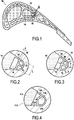
- the figure 1 shows a schematic cross-sectional view of a blade 10 cast around a refractory core 12 according to a first embodiment.
- the blade 10 is a turbine blade, but the refractory core 12 could also be used to cast other types of blades.
- the refractory core 12 is made of ceramic and will therefore be referred to below as “ceramic core 12”. More precisely, the refractory core 12 here has the following composition (mass percentages): coarse vitreous silica of 58% to 69%, fine vitreous silica from 8% to 19%, zircon (ZrSiO 4 ) 20% and cristobalite 3%. However, as previously indicated, the refractory core 12 could also be made of another material, typically refractory metal or refractory metal alloy.
- the blade 10 is hollow in order to allow it to be cooled by internal circulation of air.
- the ceramic core 12 makes it possible to form the internal cavities of the vane, the external surface of the ceramic core 12 corresponding substantially to the internal surface of the vane 10.
- the ceramic core 12 comprises a main body 14 and a shell 16.
- the ceramic core 12 comprises a single shell 16 but it could include several.
- the main body 14 and the shell 16 will now be detailed with reference to figure 2 , which presents a detail of the figure 1 .
- the shell 16 is connected to the main body 14.
- the shell 16 defines with the main body 14 a cavity 18.
- the cavity 18 is therefore located between the main body 14 and the shell 16.
- the shell 16 forms a relatively thin envelope by relative to the main body 14.
- the shell 16 is configured to come into contact with the blade 10 during manufacture.
- the main body 14 is solid.
- the presence of the shell 16 is advantageous in the regions of strong curvature of the cooling channels of the blade. Indeed, the regions of strong curvature exhibit particularly high stress concentrations.
- the shell 16 defines a convex volume, or, at least, in cross section (that is to say in the plane of the figures 1 and 2 ), the shell 16 defines a convex surface.
- the ceramic core 12 comprises a first reinforcement 20 and a second reinforcement 22.
- the first reinforcement 20 is disposed inside the cavity 18.
- the first reinforcement 20 is here rectilinear, in cross section.
- the first reinforcement 20 extends from one point of the shell 16 to another point of the shell 16, therefore passing through the cavity 18.
- the second reinforcement 22 is arranged inside the cavity 18.
- the second reinforcement 22 is here rectilinear, in cross section.
- the second reinforcement 20 extends from a point of the shell 16 to a point of the first reinforcement 20.
- the first reinforcement 20 and the second reinforcement 22 have a generally T-shaped cross section.
- the first reinforcement 20 and the second reinforcement 22 extend here over the entire length (in the longitudinal direction, that is to say along an axis perpendicular to the plane of the figure 2 ) of ceramic core 12.
- the first reinforcement 20 has an aspect ratio L / a approximately equal to 6.6.
- the second reinforcement 22 has an aspect ratio of approximately equal to 4. In any event, it is preferable that each reinforcement has an aspect ratio of between 2 and 50.
- the cavity is plugged in the vicinity of its ends in the longitudinal direction, preferably in parts of the shell which are not intended to come into contact with the cooling metal.
- the plugged parts can be manufactured continuously with the shell and the main body, as well as with any reinforcements.
- the metal vane 10 retracts more than the ceramic core 12 and exerts on the ceramic core forces F, shown schematically on the figure 3 , directed towards the main body 14.
- the ceramic core forces F shown schematically on the figure 3 , directed towards the main body 14.
- the shell 16 and the reinforcements 20, 22 are deformed.
- the first and second reinforcements have at their intersection an intermediate portion 24 forming a preferential rupture zone.
- the intermediate part 24 is dimensioned to be the first point of rupture under the effect of the forces due to the contraction of the vane 10.
- the character of preferential rupture zone of the intermediate part 24 is here ensured by the intersection of the first and second reinforcements 20, 22 in a T-shape, the intermediate part 24 being located at the intersection of the first and second reinforcements 20, 22.
- the intermediate part 24 breaks, which causes the weakening of the reinforcing structure formed by the reinforcements 20, 22 and the rupture of the shell. 16.
- the ceramic core 12 no longer hinders, at the location of the now destroyed shell 16, the free withdrawal of the blade 10. Consequently, the residual stresses in the blade 10 are greatly reduced and recrystallization phenomena can be avoided.
- the ceramic core 12 can be formed by additive manufacturing or by any other method suitable for producing the shell 16 and its possible reinforcements 20, 22. Manufacturing by ceramic injection of the solid part of the ceramic core 12 and of the shell 16 , separately, followed by gluing, for example by refractory glue, is also possible.
- the lost wax manufacturing process of the blade 10 once the ceramic core 12 has been produced is conventional and consists first of all in forming an injection mold in which the ceramic core 12 is placed before injection of the wax.
- the wax model thus created is then dipped in slips made of ceramic suspension to make a casting mold (also called shell mold). Finally, the wax is removed and the shell mold is fired into which the molten metal can then be poured.
- the cooling of the wax blade model can give rise to stresses similar to those which appear during the cooling of the metal blade 10.
- the shell 16 must not break during this step.
- a person skilled in the art can size the shell 16, for example using digital simulations, so that it withstands the forces exerted by the wax while cooling and that it breaks under pressure. effect of the more intense forces exerted by the metal in cooling.
- the ceramic core 12 is manually coated with wax.
- This step is called pre-waxing the core.
- This preliminary coating can be done directly on the surface of the ceramic core 12.
- the coating can be done on the entire surface of the ceramic core 12, only on the shell 16 or even on any part of the external surface of the ceramic core 12.
- This The preliminary coating forms a buffer layer making it possible to attenuate the forces effectively exerted on the ceramic core 12, thus protecting the shell 16 from breaking.
- the pre-wax coating can be removed from the core together with the complete wax model.
- the figure 4 presents another embodiment of the ceramic core.
- the ceramic core 112 of the figure 4 is identical to the ceramic core 12 of the first embodiment except as regards the reinforcements and the aspects detailed below.
- the main body 114, the shell 116 and the cavity 118 will not be described again.
- the ceramic core 112 comprises a first reinforcement 120 having a substantially V-shaped shape. Furthermore, the first reinforcement comprises an intermediate part 124 forming a preferential rupture zone. In this case, the intermediate part 124 takes the form of a notch in the first reinforcement. The intermediate part 124 therefore forms a stress concentration zone, which results in a preferential rupture zone.
- the ceramic core 112 is obtained by a process in which the main body 114 and the shell 116 are produced separately, for example by ceramic injection, and then assembled, for example by gluing.
Landscapes
- Engineering & Computer Science (AREA)
- Mechanical Engineering (AREA)
- Molds, Cores, And Manufacturing Methods Thereof (AREA)
- Turbine Rotor Nozzle Sealing (AREA)
Claims (11)
- Feuerfester Kern (12, 112) für die Herstellung einer hohlen Schaufel (10) einer Turbomaschine gemäß der Technik des Wachsausschmelzgießens, umfassend einen Hauptkörper (14, 114) und mindestens eine mit dem Hauptkörper (14, 114) verbundene Schale (16, 116) und definierend einen Hohlraum (18, 118) zwischen dem Hauptkörper und der Schale, wobei die Schale (16, 116) ausgelegt ist, um mit der Schaufel (10) bei der Herstellung in Kontakt zu kommen, wobei der Hohlraum (18, 118) derart verstopft ist, dass das Gießmaterial beim Gießen der Schaufel (10) nicht in den Hohlraum eindringt.
- Feuerfester Kern (12, 112) nach Anspruch 1, wobei die Schale (16, 116) ein konvexes Volumen definiert.
- Feuerfester Kern (12, 112) nach Anspruch 1 oder 2, wobei der Hauptkörper (14, 114) voll ist.
- Feuerfester Kern (12, 112) nach einem der Ansprüche 1 bis 3, umfassend ferner mindestens eine erste Verstärkung (20, 120), die im Inneren des Hohlraums (18, 118) angeordnet ist, die sich von einem Punkt der Schale (16, 116) zu einem anderen Punkt der Schale erstreckt.
- Feuerfester Kern (12) nach Anspruch 4, umfassend ferner mindestens eine zweite Verstärkung (22), die im Inneren des Hohlraums (18) angeordnet ist und sich von einem Punkt der Schale (16) zu einem Punkt der ersten Verstärkung (20) erstreckt.
- Feuerfester Kern (12, 112) nach Anspruch 4 oder Anspruch 5, wobei mindestens eine der Verstärkungen (20, 22, 120) einen Übergangsabschnitt (24, 124) aufweist, der eine bevorzugte Bruchzone bildet.
- Feuerfester Kern (12, 112) nach einem der Ansprüche 4 bis 6, wobei im Querschnitt jede Verstärkung (20, 22, 120) ein Seitenverhältnis hat, das zwischen 2 und 50 liegt.
- Feuerfester Kern (12, 112) nach einem der Ansprüche 1 bis 7, wobei der Hohlraum (18, 118) die allgemeine Form eines Rohrs hat, wobei der Hohlraum in der Nähe der Enden des Rohrs verstopft ist.
- Feuerfester Kern (12, 112) nach einem der Ansprüche 1 bis 8, wobei der Hauptkörper (14, 114) und die Schale (16, 116) einteilig sind.
- Verfahren zur Herstellung einer hohlen Schaufel (10) einer Turbomaschine gemäß der Technik des Wachsausschmelzgießens mit Hilfe eines feuerfesten Kerns (12, 112) nach einem der Ansprüche 1 bis 9.
- Herstellungsverfahren nach Anspruch 10, wobei vor dem Einleiten des Wachses auf den feuerfesten Kern (12, 112) der feuerfeste Kern (12, 112) manuell mit Wachs beschichtet wird.
Applications Claiming Priority (2)
| Application Number | Priority Date | Filing Date | Title |
|---|---|---|---|
| FR1650332A FR3046736B1 (fr) | 2016-01-15 | 2016-01-15 | Noyau refractaire comprenant un corps principal et une coque |
| PCT/FR2017/050082 WO2017121972A1 (fr) | 2016-01-15 | 2017-01-13 | Noyau réfractaire comprenant un corps principal et une coque |
Publications (2)
| Publication Number | Publication Date |
|---|---|
| EP3402621A1 EP3402621A1 (de) | 2018-11-21 |
| EP3402621B1 true EP3402621B1 (de) | 2020-12-16 |
Family
ID=55953203
Family Applications (1)
| Application Number | Title | Priority Date | Filing Date |
|---|---|---|---|
| EP17706528.1A Active EP3402621B1 (de) | 2016-01-15 | 2017-01-13 | Feuerfester kern mit einem hauptkörper und einer schale |
Country Status (8)
| Country | Link |
|---|---|
| US (1) | US10654098B2 (de) |
| EP (1) | EP3402621B1 (de) |
| CN (1) | CN108472715B (de) |
| BR (1) | BR112018014384B1 (de) |
| CA (1) | CA3011498C (de) |
| FR (1) | FR3046736B1 (de) |
| RU (1) | RU2721260C2 (de) |
| WO (1) | WO2017121972A1 (de) |
Family Cites Families (14)
| Publication number | Priority date | Publication date | Assignee | Title |
|---|---|---|---|---|
| US5295530A (en) * | 1992-02-18 | 1994-03-22 | General Motors Corporation | Single-cast, high-temperature, thin wall structures and methods of making the same |
| DE19821770C1 (de) * | 1998-05-14 | 1999-04-15 | Siemens Ag | Verfahren und Vorrichtung zur Herstellung eines metallischen Hohlkörpers |
| EP1266706A1 (de) * | 2001-06-13 | 2002-12-18 | Siemens Aktiengesellschaft | Gussvorrichtung, Verfahren zur Herstellung einer Gussvorrichtung und Verwendung einer Gussvorrichtung |
| US6929054B2 (en) | 2003-12-19 | 2005-08-16 | United Technologies Corporation | Investment casting cores |
| US7216694B2 (en) * | 2004-01-23 | 2007-05-15 | United Technologies Corporation | Apparatus and method for reducing operating stress in a turbine blade and the like |
| US6951239B1 (en) * | 2004-04-15 | 2005-10-04 | United Technologies Corporation | Methods for manufacturing investment casting shells |
| US7108045B2 (en) * | 2004-09-09 | 2006-09-19 | United Technologies Corporation | Composite core for use in precision investment casting |
| FR2878458B1 (fr) * | 2004-11-26 | 2008-07-11 | Snecma Moteurs Sa | Procede de fabrication de noyaux ceramiques de fonderie pour aubes de turbomachines, outil pour la mise en oeuvre du procede |
| US7306026B2 (en) * | 2005-09-01 | 2007-12-11 | United Technologies Corporation | Cooled turbine airfoils and methods of manufacture |
| FR2900850B1 (fr) * | 2006-05-10 | 2009-02-06 | Snecma Sa | Procede de fabrication de noyaux ceramiques de fonderie pour aubes de turbomachine |
| RU2337786C1 (ru) * | 2007-04-25 | 2008-11-10 | Федеральное государственное унитарное предприятие "Московское машиностроительное производственное предприятие "САЛЮТ" (ФГУП "ММПП "САЛЮТ") | Способ изготовления керамических форм по удаляемым моделям |
| FR2930188B1 (fr) * | 2008-04-18 | 2013-09-20 | Snecma | Procede pour ebavurer une piece en matiere ceramique. |
| FR2961552B1 (fr) | 2010-06-21 | 2014-01-31 | Snecma | Aube de turbine a cavite de bord d'attaque refroidie par impact |
| US10040115B2 (en) * | 2014-10-31 | 2018-08-07 | United Technologies Corporation | Additively manufactured casting articles for manufacturing gas turbine engine parts |
-
2016
- 2016-01-15 FR FR1650332A patent/FR3046736B1/fr not_active Expired - Fee Related
-
2017
- 2017-01-13 CN CN201780006887.7A patent/CN108472715B/zh not_active Expired - Fee Related
- 2017-01-13 CA CA3011498A patent/CA3011498C/fr active Active
- 2017-01-13 EP EP17706528.1A patent/EP3402621B1/de active Active
- 2017-01-13 US US16/069,593 patent/US10654098B2/en active Active
- 2017-01-13 WO PCT/FR2017/050082 patent/WO2017121972A1/fr not_active Ceased
- 2017-01-13 BR BR112018014384-7A patent/BR112018014384B1/pt not_active IP Right Cessation
- 2017-01-13 RU RU2018129571A patent/RU2721260C2/ru active
Non-Patent Citations (1)
| Title |
|---|
| None * |
Also Published As
| Publication number | Publication date |
|---|---|
| US10654098B2 (en) | 2020-05-19 |
| CA3011498A1 (fr) | 2017-07-20 |
| FR3046736B1 (fr) | 2021-04-23 |
| CA3011498C (fr) | 2023-05-23 |
| EP3402621A1 (de) | 2018-11-21 |
| US20190111470A1 (en) | 2019-04-18 |
| RU2721260C2 (ru) | 2020-05-18 |
| FR3046736A1 (fr) | 2017-07-21 |
| BR112018014384A2 (pt) | 2018-12-11 |
| RU2018129571A (ru) | 2020-02-18 |
| RU2018129571A3 (de) | 2020-03-12 |
| CN108472715B (zh) | 2021-01-29 |
| WO2017121972A1 (fr) | 2017-07-20 |
| CN108472715A (zh) | 2018-08-31 |
| BR112018014384B1 (pt) | 2022-07-05 |
Similar Documents
| Publication | Publication Date | Title |
|---|---|---|
| CA2954024C (fr) | Procede de fabrication d'une aube bi-composant pour moteur a turbine a gaz et aube obtenue par un tel procede | |
| EP2483011B1 (de) | Verbessertes wachsausschmelzverfahren zur herstellung einer ringförmigen turbinenmotoranordnung mit schaufeln, metallform und wachsstruktur zur implementierung solch eines verfahrens | |
| CA2872066A1 (fr) | Outillage de fabrication d'un noyau de fonderie pour une aube de turbomachine | |
| EP3414031B1 (de) | Verfahren zur bildung von entstaubungslöchern für eine turbinenschaufel und zugehöriger keramikkern | |
| EP4021663B1 (de) | Verbessertes verfahren zur herstellung eines keramischen kerns zur herstellung von turbomaschinenschaufeln und keramischer kern | |
| EP3402621B1 (de) | Feuerfester kern mit einem hauptkörper und einer schale | |
| FR2874187A1 (fr) | Procede de fabrication d'une aube de turbomachine par moulage a cire perdue | |
| EP3942155B1 (de) | Schaufel einer flugzeug-turbomaschine und ihr fertigungsverfahren mittels wachsausschmelzgiessen | |
| FR3137316A1 (fr) | Noyau céramique pour aube de turbine creuse à perçages externes | |
| EP3395469B1 (de) | Anordnung für die herstellung einer laufradschaufel eines turbotriebwerks | |
| EP4107307B1 (de) | Verfahren zum chemischen beizen eines metallgussteils mit porösem keramikkern/porösen keramikkern(en) | |
| WO2018020182A1 (fr) | Procede de realisation d'un modele non permanent | |
| FR3023197A1 (fr) | Procede de moulage d'une aube a baignoire en ceramique | |
| WO2024241005A1 (fr) | Procede de fabrication d'une aube creuse de turbine de turbomachine | |
| EP4698341A1 (de) | Durch metallgiessen hergestellter schaufelrohling eines turbinentriebwerks und verfahren zur herstellung solch eines rohlings | |
| FR3108540A1 (fr) | Moule pour la fabrication d’un noyau céramique de fonderie |
Legal Events
| Date | Code | Title | Description |
|---|---|---|---|
| STAA | Information on the status of an ep patent application or granted ep patent |
Free format text: STATUS: UNKNOWN |
|
| STAA | Information on the status of an ep patent application or granted ep patent |
Free format text: STATUS: THE INTERNATIONAL PUBLICATION HAS BEEN MADE |
|
| PUAI | Public reference made under article 153(3) epc to a published international application that has entered the european phase |
Free format text: ORIGINAL CODE: 0009012 |
|
| STAA | Information on the status of an ep patent application or granted ep patent |
Free format text: STATUS: REQUEST FOR EXAMINATION WAS MADE |
|
| 17P | Request for examination filed |
Effective date: 20180809 |
|
| AK | Designated contracting states |
Kind code of ref document: A1 Designated state(s): AL AT BE BG CH CY CZ DE DK EE ES FI FR GB GR HR HU IE IS IT LI LT LU LV MC MK MT NL NO PL PT RO RS SE SI SK SM TR |
|
| AX | Request for extension of the european patent |
Extension state: BA ME |
|
| DAV | Request for validation of the european patent (deleted) | ||
| DAX | Request for extension of the european patent (deleted) | ||
| GRAP | Despatch of communication of intention to grant a patent |
Free format text: ORIGINAL CODE: EPIDOSNIGR1 |
|
| STAA | Information on the status of an ep patent application or granted ep patent |
Free format text: STATUS: GRANT OF PATENT IS INTENDED |
|
| INTG | Intention to grant announced |
Effective date: 20200713 |
|
| GRAS | Grant fee paid |
Free format text: ORIGINAL CODE: EPIDOSNIGR3 |
|
| GRAA | (expected) grant |
Free format text: ORIGINAL CODE: 0009210 |
|
| STAA | Information on the status of an ep patent application or granted ep patent |
Free format text: STATUS: THE PATENT HAS BEEN GRANTED |
|
| AK | Designated contracting states |
Kind code of ref document: B1 Designated state(s): AL AT BE BG CH CY CZ DE DK EE ES FI FR GB GR HR HU IE IS IT LI LT LU LV MC MK MT NL NO PL PT RO RS SE SI SK SM TR |
|
| REG | Reference to a national code |
Ref country code: GB Ref legal event code: FG4D Free format text: NOT ENGLISH |
|
| REG | Reference to a national code |
Ref country code: DE Ref legal event code: R096 Ref document number: 602017029569 Country of ref document: DE |
|
| REG | Reference to a national code |
Ref country code: IE Ref legal event code: FG4D Free format text: LANGUAGE OF EP DOCUMENT: FRENCH |
|
| REG | Reference to a national code |
Ref country code: AT Ref legal event code: REF Ref document number: 1345119 Country of ref document: AT Kind code of ref document: T Effective date: 20210115 |
|
| REG | Reference to a national code |
Ref country code: SE Ref legal event code: TRGR |
|
| PG25 | Lapsed in a contracting state [announced via postgrant information from national office to epo] |
Ref country code: RS Free format text: LAPSE BECAUSE OF FAILURE TO SUBMIT A TRANSLATION OF THE DESCRIPTION OR TO PAY THE FEE WITHIN THE PRESCRIBED TIME-LIMIT Effective date: 20201216 Ref country code: NO Free format text: LAPSE BECAUSE OF FAILURE TO SUBMIT A TRANSLATION OF THE DESCRIPTION OR TO PAY THE FEE WITHIN THE PRESCRIBED TIME-LIMIT Effective date: 20210316 Ref country code: GR Free format text: LAPSE BECAUSE OF FAILURE TO SUBMIT A TRANSLATION OF THE DESCRIPTION OR TO PAY THE FEE WITHIN THE PRESCRIBED TIME-LIMIT Effective date: 20210317 Ref country code: FI Free format text: LAPSE BECAUSE OF FAILURE TO SUBMIT A TRANSLATION OF THE DESCRIPTION OR TO PAY THE FEE WITHIN THE PRESCRIBED TIME-LIMIT Effective date: 20201216 |
|
| REG | Reference to a national code |
Ref country code: AT Ref legal event code: MK05 Ref document number: 1345119 Country of ref document: AT Kind code of ref document: T Effective date: 20201216 |
|
| REG | Reference to a national code |
Ref country code: NL Ref legal event code: MP Effective date: 20201216 |
|
| PG25 | Lapsed in a contracting state [announced via postgrant information from national office to epo] |
Ref country code: BG Free format text: LAPSE BECAUSE OF FAILURE TO SUBMIT A TRANSLATION OF THE DESCRIPTION OR TO PAY THE FEE WITHIN THE PRESCRIBED TIME-LIMIT Effective date: 20210316 Ref country code: LV Free format text: LAPSE BECAUSE OF FAILURE TO SUBMIT A TRANSLATION OF THE DESCRIPTION OR TO PAY THE FEE WITHIN THE PRESCRIBED TIME-LIMIT Effective date: 20201216 |
|
| PG25 | Lapsed in a contracting state [announced via postgrant information from national office to epo] |
Ref country code: NL Free format text: LAPSE BECAUSE OF FAILURE TO SUBMIT A TRANSLATION OF THE DESCRIPTION OR TO PAY THE FEE WITHIN THE PRESCRIBED TIME-LIMIT Effective date: 20201216 Ref country code: HR Free format text: LAPSE BECAUSE OF FAILURE TO SUBMIT A TRANSLATION OF THE DESCRIPTION OR TO PAY THE FEE WITHIN THE PRESCRIBED TIME-LIMIT Effective date: 20201216 |
|
| REG | Reference to a national code |
Ref country code: LT Ref legal event code: MG9D |
|
| PG25 | Lapsed in a contracting state [announced via postgrant information from national office to epo] |
Ref country code: LT Free format text: LAPSE BECAUSE OF FAILURE TO SUBMIT A TRANSLATION OF THE DESCRIPTION OR TO PAY THE FEE WITHIN THE PRESCRIBED TIME-LIMIT Effective date: 20201216 Ref country code: EE Free format text: LAPSE BECAUSE OF FAILURE TO SUBMIT A TRANSLATION OF THE DESCRIPTION OR TO PAY THE FEE WITHIN THE PRESCRIBED TIME-LIMIT Effective date: 20201216 Ref country code: CZ Free format text: LAPSE BECAUSE OF FAILURE TO SUBMIT A TRANSLATION OF THE DESCRIPTION OR TO PAY THE FEE WITHIN THE PRESCRIBED TIME-LIMIT Effective date: 20201216 Ref country code: SM Free format text: LAPSE BECAUSE OF FAILURE TO SUBMIT A TRANSLATION OF THE DESCRIPTION OR TO PAY THE FEE WITHIN THE PRESCRIBED TIME-LIMIT Effective date: 20201216 Ref country code: RO Free format text: LAPSE BECAUSE OF FAILURE TO SUBMIT A TRANSLATION OF THE DESCRIPTION OR TO PAY THE FEE WITHIN THE PRESCRIBED TIME-LIMIT Effective date: 20201216 Ref country code: SK Free format text: LAPSE BECAUSE OF FAILURE TO SUBMIT A TRANSLATION OF THE DESCRIPTION OR TO PAY THE FEE WITHIN THE PRESCRIBED TIME-LIMIT Effective date: 20201216 Ref country code: PT Free format text: LAPSE BECAUSE OF FAILURE TO SUBMIT A TRANSLATION OF THE DESCRIPTION OR TO PAY THE FEE WITHIN THE PRESCRIBED TIME-LIMIT Effective date: 20210416 |
|
| PG25 | Lapsed in a contracting state [announced via postgrant information from national office to epo] |
Ref country code: AT Free format text: LAPSE BECAUSE OF FAILURE TO SUBMIT A TRANSLATION OF THE DESCRIPTION OR TO PAY THE FEE WITHIN THE PRESCRIBED TIME-LIMIT Effective date: 20201216 Ref country code: PL Free format text: LAPSE BECAUSE OF FAILURE TO SUBMIT A TRANSLATION OF THE DESCRIPTION OR TO PAY THE FEE WITHIN THE PRESCRIBED TIME-LIMIT Effective date: 20201216 |
|
| REG | Reference to a national code |
Ref country code: CH Ref legal event code: PL |
|
| REG | Reference to a national code |
Ref country code: DE Ref legal event code: R097 Ref document number: 602017029569 Country of ref document: DE |
|
| PG25 | Lapsed in a contracting state [announced via postgrant information from national office to epo] |
Ref country code: IS Free format text: LAPSE BECAUSE OF FAILURE TO SUBMIT A TRANSLATION OF THE DESCRIPTION OR TO PAY THE FEE WITHIN THE PRESCRIBED TIME-LIMIT Effective date: 20210416 Ref country code: MC Free format text: LAPSE BECAUSE OF FAILURE TO SUBMIT A TRANSLATION OF THE DESCRIPTION OR TO PAY THE FEE WITHIN THE PRESCRIBED TIME-LIMIT Effective date: 20201216 Ref country code: LU Free format text: LAPSE BECAUSE OF NON-PAYMENT OF DUE FEES Effective date: 20210113 |
|
| REG | Reference to a national code |
Ref country code: BE Ref legal event code: MM Effective date: 20210131 |
|
| PLBE | No opposition filed within time limit |
Free format text: ORIGINAL CODE: 0009261 |
|
| STAA | Information on the status of an ep patent application or granted ep patent |
Free format text: STATUS: NO OPPOSITION FILED WITHIN TIME LIMIT |
|
| PG25 | Lapsed in a contracting state [announced via postgrant information from national office to epo] |
Ref country code: AL Free format text: LAPSE BECAUSE OF FAILURE TO SUBMIT A TRANSLATION OF THE DESCRIPTION OR TO PAY THE FEE WITHIN THE PRESCRIBED TIME-LIMIT Effective date: 20201216 |
|
| 26N | No opposition filed |
Effective date: 20210917 |
|
| PG25 | Lapsed in a contracting state [announced via postgrant information from national office to epo] |
Ref country code: LI Free format text: LAPSE BECAUSE OF NON-PAYMENT OF DUE FEES Effective date: 20210131 Ref country code: CH Free format text: LAPSE BECAUSE OF NON-PAYMENT OF DUE FEES Effective date: 20210131 Ref country code: DK Free format text: LAPSE BECAUSE OF FAILURE TO SUBMIT A TRANSLATION OF THE DESCRIPTION OR TO PAY THE FEE WITHIN THE PRESCRIBED TIME-LIMIT Effective date: 20201216 |
|
| PG25 | Lapsed in a contracting state [announced via postgrant information from national office to epo] |
Ref country code: ES Free format text: LAPSE BECAUSE OF FAILURE TO SUBMIT A TRANSLATION OF THE DESCRIPTION OR TO PAY THE FEE WITHIN THE PRESCRIBED TIME-LIMIT Effective date: 20201216 Ref country code: IE Free format text: LAPSE BECAUSE OF NON-PAYMENT OF DUE FEES Effective date: 20210113 |
|
| PG25 | Lapsed in a contracting state [announced via postgrant information from national office to epo] |
Ref country code: SI Free format text: LAPSE BECAUSE OF FAILURE TO SUBMIT A TRANSLATION OF THE DESCRIPTION OR TO PAY THE FEE WITHIN THE PRESCRIBED TIME-LIMIT Effective date: 20201216 |
|
| PG25 | Lapsed in a contracting state [announced via postgrant information from national office to epo] |
Ref country code: IS Free format text: LAPSE BECAUSE OF FAILURE TO SUBMIT A TRANSLATION OF THE DESCRIPTION OR TO PAY THE FEE WITHIN THE PRESCRIBED TIME-LIMIT Effective date: 20210416 |
|
| PG25 | Lapsed in a contracting state [announced via postgrant information from national office to epo] |
Ref country code: BE Free format text: LAPSE BECAUSE OF NON-PAYMENT OF DUE FEES Effective date: 20210131 |
|
| PG25 | Lapsed in a contracting state [announced via postgrant information from national office to epo] |
Ref country code: CY Free format text: LAPSE BECAUSE OF FAILURE TO SUBMIT A TRANSLATION OF THE DESCRIPTION OR TO PAY THE FEE WITHIN THE PRESCRIBED TIME-LIMIT Effective date: 20201216 |
|
| PG25 | Lapsed in a contracting state [announced via postgrant information from national office to epo] |
Ref country code: HU Free format text: LAPSE BECAUSE OF FAILURE TO SUBMIT A TRANSLATION OF THE DESCRIPTION OR TO PAY THE FEE WITHIN THE PRESCRIBED TIME-LIMIT; INVALID AB INITIO Effective date: 20170113 |
|
| PGFP | Annual fee paid to national office [announced via postgrant information from national office to epo] |
Ref country code: GB Payment date: 20231219 Year of fee payment: 8 |
|
| PGFP | Annual fee paid to national office [announced via postgrant information from national office to epo] |
Ref country code: SE Payment date: 20231219 Year of fee payment: 8 |
|
| PG25 | Lapsed in a contracting state [announced via postgrant information from national office to epo] |
Ref country code: MK Free format text: LAPSE BECAUSE OF FAILURE TO SUBMIT A TRANSLATION OF THE DESCRIPTION OR TO PAY THE FEE WITHIN THE PRESCRIBED TIME-LIMIT Effective date: 20201216 |
|
| PGFP | Annual fee paid to national office [announced via postgrant information from national office to epo] |
Ref country code: DE Payment date: 20231219 Year of fee payment: 8 |
|
| PGFP | Annual fee paid to national office [announced via postgrant information from national office to epo] |
Ref country code: IT Payment date: 20240102 Year of fee payment: 8 |
|
| PG25 | Lapsed in a contracting state [announced via postgrant information from national office to epo] |
Ref country code: MT Free format text: LAPSE BECAUSE OF FAILURE TO SUBMIT A TRANSLATION OF THE DESCRIPTION OR TO PAY THE FEE WITHIN THE PRESCRIBED TIME-LIMIT Effective date: 20201216 |
|
| REG | Reference to a national code |
Ref country code: DE Ref legal event code: R119 Ref document number: 602017029569 Country of ref document: DE |
|
| REG | Reference to a national code |
Ref country code: SE Ref legal event code: EUG |
|
| GBPC | Gb: european patent ceased through non-payment of renewal fee |
Effective date: 20250113 |
|
| PG25 | Lapsed in a contracting state [announced via postgrant information from national office to epo] |
Ref country code: DE Free format text: LAPSE BECAUSE OF NON-PAYMENT OF DUE FEES Effective date: 20250801 |
|
| PG25 | Lapsed in a contracting state [announced via postgrant information from national office to epo] |
Ref country code: GB Free format text: LAPSE BECAUSE OF NON-PAYMENT OF DUE FEES Effective date: 20250113 |
|
| PG25 | Lapsed in a contracting state [announced via postgrant information from national office to epo] |
Ref country code: TR Free format text: LAPSE BECAUSE OF FAILURE TO SUBMIT A TRANSLATION OF THE DESCRIPTION OR TO PAY THE FEE WITHIN THE PRESCRIBED TIME-LIMIT Effective date: 20201216 |
|
| PG25 | Lapsed in a contracting state [announced via postgrant information from national office to epo] |
Ref country code: IT Free format text: LAPSE BECAUSE OF NON-PAYMENT OF DUE FEES Effective date: 20250113 |
|
| PGFP | Annual fee paid to national office [announced via postgrant information from national office to epo] |
Ref country code: FR Payment date: 20260128 Year of fee payment: 10 |