EP3402016A1 - Laser level - Google Patents
Laser level Download PDFInfo
- Publication number
- EP3402016A1 EP3402016A1 EP18170125.1A EP18170125A EP3402016A1 EP 3402016 A1 EP3402016 A1 EP 3402016A1 EP 18170125 A EP18170125 A EP 18170125A EP 3402016 A1 EP3402016 A1 EP 3402016A1
- Authority
- EP
- European Patent Office
- Prior art keywords
- laser
- cone
- transparent member
- hollow transparent
- laser module
- Prior art date
- Legal status (The legal status is an assumption and is not a legal conclusion. Google has not performed a legal analysis and makes no representation as to the accuracy of the status listed.)
- Granted
Links
Images


Classifications
-
- G—PHYSICS
- G01—MEASURING; TESTING
- G01C—MEASURING DISTANCES, LEVELS OR BEARINGS; SURVEYING; NAVIGATION; GYROSCOPIC INSTRUMENTS; PHOTOGRAMMETRY OR VIDEOGRAMMETRY
- G01C15/00—Surveying instruments or accessories not provided for in groups G01C1/00 - G01C13/00
- G01C15/002—Active optical surveying means
- G01C15/004—Reference lines, planes or sectors
-
- G—PHYSICS
- G02—OPTICS
- G02B—OPTICAL ELEMENTS, SYSTEMS OR APPARATUS
- G02B27/00—Optical systems or apparatus not provided for by any of the groups G02B1/00 - G02B26/00, G02B30/00
- G02B27/10—Beam splitting or combining systems
- G02B27/106—Beam splitting or combining systems for splitting or combining a plurality of identical beams or images, e.g. image replication
-
- G—PHYSICS
- G02—OPTICS
- G02B—OPTICAL ELEMENTS, SYSTEMS OR APPARATUS
- G02B27/00—Optical systems or apparatus not provided for by any of the groups G02B1/00 - G02B26/00, G02B30/00
- G02B27/10—Beam splitting or combining systems
- G02B27/108—Beam splitting or combining systems for sampling a portion of a beam or combining a small beam in a larger one, e.g. wherein the area ratio or power ratio of the divided beams significantly differs from unity, without spectral selectivity
-
- G—PHYSICS
- G02—OPTICS
- G02B—OPTICAL ELEMENTS, SYSTEMS OR APPARATUS
- G02B27/00—Optical systems or apparatus not provided for by any of the groups G02B1/00 - G02B26/00, G02B30/00
- G02B27/10—Beam splitting or combining systems
- G02B27/14—Beam splitting or combining systems operating by reflection only
-
- G—PHYSICS
- G02—OPTICS
- G02B—OPTICAL ELEMENTS, SYSTEMS OR APPARATUS
- G02B5/00—Optical elements other than lenses
- G02B5/001—Axicons, waxicons, reflaxicons
-
- H—ELECTRICITY
- H01—ELECTRIC ELEMENTS
- H01S—DEVICES USING THE PROCESS OF LIGHT AMPLIFICATION BY STIMULATED EMISSION OF RADIATION [LASER] TO AMPLIFY OR GENERATE LIGHT; DEVICES USING STIMULATED EMISSION OF ELECTROMAGNETIC RADIATION IN WAVE RANGES OTHER THAN OPTICAL
- H01S5/00—Semiconductor lasers
- H01S5/005—Optical components external to the laser cavity, specially adapted therefor, e.g. for homogenisation or merging of the beams or for manipulating laser pulses, e.g. pulse shaping
- H01S5/0071—Optical components external to the laser cavity, specially adapted therefor, e.g. for homogenisation or merging of the beams or for manipulating laser pulses, e.g. pulse shaping for beam steering, e.g. using a mirror outside the cavity to change the beam direction
-
- H—ELECTRICITY
- H01—ELECTRIC ELEMENTS
- H01S—DEVICES USING THE PROCESS OF LIGHT AMPLIFICATION BY STIMULATED EMISSION OF RADIATION [LASER] TO AMPLIFY OR GENERATE LIGHT; DEVICES USING STIMULATED EMISSION OF ELECTROMAGNETIC RADIATION IN WAVE RANGES OTHER THAN OPTICAL
- H01S5/00—Semiconductor lasers
- H01S5/02—Structural details or components not essential to laser action
- H01S5/022—Mountings; Housings
- H01S5/02208—Mountings; Housings characterised by the shape of the housings
- H01S5/02212—Can-type, e.g. TO-CAN housings with emission along or parallel to symmetry axis
Definitions
- the present invention relates to laser levels, particularly laser levels with an improved construction.
- a first aspect of the present invention provides a laser level according to Claim 1.
- Preferred and other optional features of the invention are described and defined in the dependent claims.
- a laser level comprising a housing and a laser module assembly.
- the laser module assembly is at least partially housed in the housing.
- the laser module assembly includes a laser module.
- the laser module includes a laser generator, a transparent member and a cone member.
- the laser generator generates a laser beam which is directed towards a cone member.
- the cone member reflects and projects the laser beam into a laser line.
- the transparent member has a generally cylindrical shape.
- the cone member includes a cone section including a reflecting surface and the cone section is located inside the transparent member.
- the cone member further includes a connection portion, the connection portion including a flange. The flange is located outside the transparent member at an outer surface of the transparent member.
- connection portion may wrap around an end of the transparent member.
- the laser level may further include an adhesive between the flange and the outer surface of the transparent member.
- the transparent member may comprise glass.
- the cone member may comprise metal.
- the cone member may comprise aluminum.
- the cone member may made as one piece.
- the cone section may comprise aluminum.
- a coefficient of thermal expansion of the cone member may be at least twice as much as a thermal expansion coefficient of the transparent member.
- a coefficient of thermal expansion of the cone section may be at least twice as much as a thermal expansion coefficient of the transparent member.
- a coefficient of thermal expansion of the connection section may be at least twice as much as a thermal expansion coefficient of the transparent member.
- a laser level including a housing and a laser module assembly, the laser module assembly at least partially housed in the housing.
- the laser module assembly includes a pendulum and a laser module on the pendulum.
- the laser module includes a laser generator, a transparent member and a cone member.
- the laser generator generating a laser beam which is directed towards the cone member.
- the cone member is one integral piece and comprises a connection section and a cone section.
- the cone section has a reflective surface and the reflective surface reflects the laser beam into a laser line which exits the housing and is configured to project on a surface.
- the transparent member has a generally cylindrical shape with an inner surface, and outer surface opposite the inner surface.
- the reflective surface is located inside the transparent member and reflects the laser beam from the inside of the transparent member out through the transparent member.
- the connection section connects the cone member to the transparent member and wherein the connection section wraps around an end of the transparent member and includes a flange which is disposed around a portion of the outer surface of the transparent member.
- the transparent member may comprise glass.
- the cone member may comprise metal.
- At least the flange of the cone member may undergo thermal expansion and contraction at a rate at least 50 % greater than the rate of thermal expansion and contraction of the portion of the outer surface of the transparent member around which the flange is disposed.
- At least the flange of the cone member may undergo thermal expansion and contraction at a rate at least 100 % greater than the rate of thermal expansion and contraction of the portion of the outer surface of the transparent member around which the flange is disposed.
- a laser level including a housing and a laser module assembly.
- the laser module assembly is at least partially housed in the housing and includes a pendulum assembly configured to rotate under the effects of gravity and a laser module on the pendulum assembly.
- the laser module includes a laser generator, a transparent member and a cone member, the laser generator generating a laser beam which is directed towards the cone member.
- the cone member is one integral piece and comprises a connection section and a cone section.
- the cone section has a reflective surface. The reflective surface reflects the laser beam into a laser line which exits the housing and is configured to project on an external surface outside of the laser level.
- the transparent member has a generally cylindrical shape with an inner surface, and outer surface opposite the inner surface.
- the reflective surface is located inside the transparent member and reflects the laser beam from the inside of the transparent member out through the transparent member.
- the connection section connects the cone member to the transparent member and wherein the connection section wraps around an end of the transparent member and includes a flange which is disposed outside the transparent member adjacent the outer surface. There preferably is an adhesive between the flange and the outer surface of the transparent member which adheres the cone member to the transparent member.
- a coefficient of thermal expansion of the cone member may be at least twice as much as a thermal expansion coefficient of the transparent member.
- a coefficient of thermal expansion of the cone section may be at least twice as much as a thermal expansion coefficient of the transparent member.
- a coefficient of thermal expansion of the connection section may be at least twice as much as a thermal expansion coefficient of the transparent member.
- a method of making a laser module for a laser level including forming an integral, one-piece cone member, the cone member including a connection section and a cone section, the cone section having a reflective surface and the connection section having a flange.
- the method may also include providing a laser generating source which generates a laser beam which is reflected off of the cone member.
- the method includes forming a cone member, the cone member including a connection section and a cone section, the cone section having a reflective surface and the connection section having a flange.
- the method further includes connecting the cone member to a transparent member by joining the cone member to the transparent member at one end of the transparent member so that the connection section wraps around an end of the transparent member and the flange is disposed outside the transparent member adjacent an outer surface of the transparent member.
- the cone member may be joined to the transparent member by an adhesive.
- the adhesive may be deposited on one or both of the cone member and the transparent member before joining.
- the adhesive may be deposited on the cone member at the flange.
- the adhesive may be deposited on the transparent member on an outer surface of the transparent member.
- the cone member and transparent member may be part of a laser module which includes a laser generating source.
- the laser generating source may generate a laser beam which is directed towards the cone member and is reflected by the cone member.
- the laser beam may be reflected by a conical section of the cone member.
- the conical section may have a reflective surface which reflects the cone member.
- the laser module may be disposed on a pendulum.
- the laser module assembly may be housed in a housing.
- the laser diode may be powered by a removable power tool battery pack.
- FIG. 1 is a perspective view of the laser level.
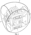
- Figs. 2 and 3 illustrate the laser level shown with laser lines 22, 32 and 42 projecting from the laser level 10.
- Fig. 2 is a perspective view of the laser level 10 and
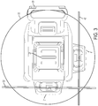
- Fig. 3 is a top view of the laser level 10.
- the laser level 10 of the exemplary embodiment includes a housing 12.
- a battery pack 20 is removably attached to the housing 12 and powers the laser level 10.
- the battery pack 20 may be a power tool battery pack which can also be coupled with power tools such as drills, sanders, saws, etc., to provide power to those tools.
- the battery pack 20 houses a plurality of battery cells (not shown).
- the battery cells may be cylindrical lithium-ion battery cells or may have other battery chemistries or geometries.
- the laser level includes three projector portions 21, 31 and 41.
- the projectors portions 21, 31, 41 are protected openings through which laser modules 50 extend so that the laser modules 50 can project laser lines 22, 32 and 42 outside of the housing 12 onto an external surface.
- laser line 22 projects out of the housing 12 at projector 21.
- Laser line 22 is configured to define a horizontal plane when the laser level 10 is set on a horizontal surface.
- Laser line 32 projects out of the housing 10 at projector 31.
- Laser line 32 is configured to define a vertical plane when the laser level 10 is set on a horizontal surface.
- Laser line 42 projects out of the housing 10 at projector 41.
- Laser line 42 is configured to define another vertical plane when the laser level 10 is set on a horizontal surface.
- laser line 42 is perpendicular to laser lines 32 and 22.
- Fig. 4 illustrates a laser module assembly 100.
- the laser module assembly 100 is housed in the housing 12 of the laser level 10.
- the laser module assembly 100 includes three laser modules 50.
- the three laser modules 50 are carried on a pendulum assembly 110.
- Pendulum assemblies are well known in the art.
- the pendulum assembly 110 rotates about a relatively small angle so that the laser modules 50 project beams in the horizontal and vertical planes, as previously discussed, when placed on a surface that is not entirely horizontally flat. For example, if the laser level 10 is placed on a surface that is sloped five degrees (5°) with respect to horizontal, the pendulum assembly 110 will tilt under the influence of gravity so that the laser modules 50 are aligned to produce a laser line 22 in a horizontal plane and laser lines 32 and 42 in vertical planes.
- the laser level 10 includes a locking device to lock the pendulum assembly 110.
- the pendulum assembly 110 will be locked in a particular position rather than allowed to rotate under the influence of gravity and it may produce laser lines offset from the vertical and horizontal.
- Figs. 5 and 6 illustrate the laser module assembly 100 projecting laser lines 22, 32 and 42. As will be appreciated, these laser lines 22, 32, 42 project out of the laser level 10 at the projector portions 21, 31 and 41.
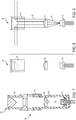
- Figs. 7-15 illustrate the laser modules 50 of the exemplary embodiment.
- Fig. 7 illustrates a cross-sectional view of a fully assembled laser module 50.
- a perspective view of an assembled laser module 50 is shown in Fig. 10 .
- Figs. 8 and 9 are side views of selected components of the laser module 50.
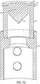
- Figs. 11 , 13 and 15 are side cross-sectional views of selected components of the laser module 50 and
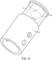
- Fig. 14 is perspective view of selected components of the laser module 50.
- Fig. 12 is perspective view of the cone member 68.
- the laser module 50 includes a laser diode 51.
- the laser diode 51 serves as a laser generating source.
- Other laser generating members may be used as a laser generating source to generate a laser beam in other embodiments.
- the laser diode 51 is held in a first barrel 53.
- a collimating lens 52 is also held in the first barrel 53.
- the first barrel 53 is generally cylindrically shaped.
- a second barrel 54 is disposed at a top end of the first barrel 53.
- the second barrel 54 is also generally cylindrically shaped and fits over the outer surface of the first barrel 53.
- the second barrel 54 may be attached to the first barrel 53 in any of a number of manners. For example, they may, among other things, be frictionally fit together, adhered together by an adhesive, soldered together, kept together by fasteners or they may be attached by a combination of the preceding or other attachment methods.
- the laser modules 50 also include a transparent member 61 which fits inside the second barrel 54 at a first end.
- the transparent member 61 is cylindrical and hollow. An outer surface of the transparent member 61 contacts an inner surface of the second barrel 54.
- the transparent member 61 may be attached to the second barrel 54 in any of a number of manners, including those listed above for attachment of the first and second barrels 53, 54.
- a cone member 68 is attached at a top of the transparent member 61.
- the cone member 68 includes a connection portion 65.
- the connection portion 65 has a top that is flat and has a circular shape.
- the connection portion 65 also includes a flange 66 at its outer edge.
- the flange 66 includes a chamfer 67. As shown in various Figs., such as Figs. 11 , 13 and 14 , the flange 66 extends around an end of the transparent member 61.
- a base portion 64 extends from the connection portion 65 towards the laser diode 51.
- the base portion 64 has a cylindrical shape.
- a cone section 63 which has the shape of a right angle cone.
- An outer surface of the cone section 63 reflects the laser from the laser diode 51.
- the cone member 68 may be entirely made of an aluminum material that is reflective. Alternatively or additionally, an outer surface of the cone section 63 may be coated with a reflective material. Operation of the cone member 68 will be explained with reference to Fig. 9 .
- the laser diode 51 produces a laser beam 90.
- the laser beam 90 passes through and is collimated by the collimating lens 52.
- the collimated beam 91 travels to the cone member 68 where it is reflected off of the outer surface of the cone section 63.
- the reflected beam forms one of the previously discussed laser lines 22, 32, 42.
- the collimated beam 91 may be offset from an apex of the cone section 63 to provide less than a 360 degree line/plane output or more or less power in a certain direction or directions.
- the cone section could be less than a full cone, such as a half cone.
- a top or bottom of the cone shape could also be truncated.
- there could be a section of a different shape to provide a different output or only the portion of the cone that is necessary for reflection may be used.
- the cone member 68 of the exemplary embodiment is made of aluminum by a single pointer diamond turning process and may have a thermal expansion coefficient of around 20 x 10 ⁇ -6/K. Accordingly, the cone member 68 of the exemplary embodiment is an integral, one-piece part, rather than, for example, the connection section 65 being a separate part connected to the base portion 64 by an adhesive.
- the cone member 68 may be multiple parts.
- the connection section 65 may be a separate part connected to the base portion 64 by an adhesive or other means.
- the materials of the different parts of the cone member 68 may be made of different materials.
- the connection section 65 may be made of a first metal material and the cone section 63 may be made of a second metal material, different than the first metal material.
- the cone section 63 is made of aluminum and a surface of it is reflective. In other embodiments, a reflective coating could be used on the cone surface.
- the transparent member of the exemplary embodiment is made of glass, such as quartz or borosilicate and may have a thermal expansion coefficient of around 0.6 x 10 ⁇ -6/K or 3.3 x 10 ⁇ -6/K, respectively. Accordingly, the thermal expansion coefficient of the cone member 68 is different, specifically larger in the exemplary embodiment, than that of the transparent member 61. In some embodiments, the thermal expansion coefficient of the cone member 68 may be 2, 3, 4 or 5 times as large as the thermal expansion coefficient of the transparent member 61.
- the cone member 68 is secured to the transparent member 61 by an adhesive 58.
- the adhesive is disposed between the flange 66 and an outer surface of the transparent member 61.
- Arranging the flange 67 around the outside of the transparent member 61 is beneficial in accommodating thermal expansion and contraction between the cone member 68 and the transparent member 61.
- the shape allows for even expansion and compression of the cone member 68 and helps to prevent non-linear expansion/compression.
- the adhesive also provides some additional buffering.
- the adhesive 58 may be put on the cone member 68 at the flange 66 and then the cone member 68 placed on the transparent member 61.
- the adhesive 58 may be put on the flange 66 and then the cone member 68 secured to the transparent member 61 or adhesive may be put on both the cone member 68 and the transparent member 61.
- the joined cone member 68 and transparent member 61 may be assembled with the other parts of the laser level 10 in various orders. For example, after the cone member 68 is adhered to the transparent member 61, the transparent member may be connected to the second barrel 54 and the remaining parts of the laser module 50.
- the laser module 50 may then be assembled with the pendulum 110 to form the laser module assembly 100.
- the laser module assembly 100 can then be assembled into the housing 12.
- the housing 12 may consist of two clamshell parts which are fixed together to house the laser module assembly. As noted, different orders of assembly of the parts are contemplated.
- the transparent member 61 may be assembled with the second barrel member 54 before the transparent member 61 cone member 68 is assembled to the transparent member.
- the second barrel member 54 may be attached to the first barrel member 53 before or after the second barrel member 54 is attached to the transparent member 61, for example.
Landscapes
- Physics & Mathematics (AREA)
- General Physics & Mathematics (AREA)
- Optics & Photonics (AREA)
- Condensed Matter Physics & Semiconductors (AREA)
- Electromagnetism (AREA)
- Engineering & Computer Science (AREA)
- Radar, Positioning & Navigation (AREA)
- Remote Sensing (AREA)
- Spectroscopy & Molecular Physics (AREA)
- Semiconductor Lasers (AREA)
Abstract
Description
- The present invention relates to laser levels, particularly laser levels with an improved construction.
- There are various existing laser levels. It is desired to provide a laser level with an improved construction.
- A first aspect of the present invention provides a laser level according to Claim 1. Preferred and other optional features of the invention are described and defined in the dependent claims.
- According to an aspect of the invention, there is a laser level, comprising a housing and a laser module assembly. The laser module assembly is at least partially housed in the housing. The laser module assembly includes a laser module. The laser module includes a laser generator, a transparent member and a cone member. The laser generator generates a laser beam which is directed towards a cone member. The cone member reflects and projects the laser beam into a laser line. The transparent member has a generally cylindrical shape. The cone member includes a cone section including a reflecting surface and the cone section is located inside the transparent member. The cone member further includes a connection portion, the connection portion including a flange. The flange is located outside the transparent member at an outer surface of the transparent member.
- The connection portion may wrap around an end of the transparent member.
- The laser level may further include an adhesive between the flange and the outer surface of the transparent member.
- The transparent member may comprise glass.
- The cone member may comprise metal.
- The cone member may comprise aluminum.
- The cone member may made as one piece.
- The cone section may comprise aluminum.
- A coefficient of thermal expansion of the cone member may be at least twice as much as a thermal expansion coefficient of the transparent member.
- A coefficient of thermal expansion of the cone section may be at least twice as much as a thermal expansion coefficient of the transparent member.
- A coefficient of thermal expansion of the connection section may be at least twice as much as a thermal expansion coefficient of the transparent member.
- According to another aspect of the invention, there is a laser level including a housing and a laser module assembly, the laser module assembly at least partially housed in the housing. The laser module assembly includes a pendulum and a laser module on the pendulum. The laser module includes a laser generator, a transparent member and a cone member. The laser generator generating a laser beam which is directed towards the cone member. The cone member is one integral piece and comprises a connection section and a cone section. The cone section has a reflective surface and the reflective surface reflects the laser beam into a laser line which exits the housing and is configured to project on a surface. The transparent member has a generally cylindrical shape with an inner surface, and outer surface opposite the inner surface. The reflective surface is located inside the transparent member and reflects the laser beam from the inside of the transparent member out through the transparent member. The connection section connects the cone member to the transparent member and wherein the connection section wraps around an end of the transparent member and includes a flange which is disposed around a portion of the outer surface of the transparent member.
- The transparent member may comprise glass.
- The cone member may comprise metal.
- At least the flange of the cone member may undergo thermal expansion and contraction at a rate at least 50 % greater than the rate of thermal expansion and contraction of the portion of the outer surface of the transparent member around which the flange is disposed.
- At least the flange of the cone member may undergo thermal expansion and contraction at a rate at least 100 % greater than the rate of thermal expansion and contraction of the portion of the outer surface of the transparent member around which the flange is disposed.
- According to another aspect of the invention, there is a laser level including a housing and a laser module assembly. The laser module assembly is at least partially housed in the housing and includes a pendulum assembly configured to rotate under the effects of gravity and a laser module on the pendulum assembly. The laser module includes a laser generator, a transparent member and a cone member, the laser generator generating a laser beam which is directed towards the cone member. The cone member is one integral piece and comprises a connection section and a cone section. The cone section has a reflective surface. The reflective surface reflects the laser beam into a laser line which exits the housing and is configured to project on an external surface outside of the laser level. The transparent member has a generally cylindrical shape with an inner surface, and outer surface opposite the inner surface. The reflective surface is located inside the transparent member and reflects the laser beam from the inside of the transparent member out through the transparent member. The connection section connects the cone member to the transparent member and wherein the connection section wraps around an end of the transparent member and includes a flange which is disposed outside the transparent member adjacent the outer surface. There preferably is an adhesive between the flange and the outer surface of the transparent member which adheres the cone member to the transparent member.
- A coefficient of thermal expansion of the cone member may be at least twice as much as a thermal expansion coefficient of the transparent member.
- A coefficient of thermal expansion of the cone section may be at least twice as much as a thermal expansion coefficient of the transparent member.
- A coefficient of thermal expansion of the connection section may be at least twice as much as a thermal expansion coefficient of the transparent member.
- According to another aspect of the invention, there is a method of making a laser module for a laser level, the method including forming an integral, one-piece cone member, the cone member including a connection section and a cone section, the cone section having a reflective surface and the connection section having a flange. Forming a transparent member, the transparent member having an inner surface and an outer surface. Applying adhesive to at least one of the transparent member and the cone member. Joining the cone member to the transparent member such that the connection section wraps around an end of the transparent member and the flange which is disposed outside the transparent member adjacent an outer surface of the transparent member.
- The method may also include providing a laser generating source which generates a laser beam which is reflected off of the cone member.
- According to another aspect of the invention, there is method of manufacturing a laser level. The method includes forming a cone member, the cone member including a connection section and a cone section, the cone section having a reflective surface and the connection section having a flange. The method further includes connecting the cone member to a transparent member by joining the cone member to the transparent member at one end of the transparent member so that the connection section wraps around an end of the transparent member and the flange is disposed outside the transparent member adjacent an outer surface of the transparent member.
- The cone member may be joined to the transparent member by an adhesive.
- The adhesive may be deposited on one or both of the cone member and the transparent member before joining.
- The adhesive may be deposited on the cone member at the flange.
- The adhesive may be deposited on the transparent member on an outer surface of the transparent member.
- When assembled, there is an adhesive between the flange and the outer surface of the transparent member which adheres the cone member to the transparent member.
- The cone member and transparent member may be part of a laser module which includes a laser generating source.
- The laser generating source may generate a laser beam which is directed towards the cone member and is reflected by the cone member.
- The laser beam may be reflected by a conical section of the cone member.
- The conical section may have a reflective surface which reflects the cone member.
- The laser module may be disposed on a pendulum.
- There may be more than one laser module on the pendulum, the laser modules and pendulum together forming a laser module assembly.
- There may be three laser modules on the pendulum.
- The laser module assembly may be housed in a housing.
- The laser diode may be powered by a removable power tool battery pack.
- It is to be understood that any feature of any aspect of the invention may be a feature of any other aspect of the invention.
- An embodiment of the invention will now be described, by way of example, with reference to the accompanying figures, of which:
-
Fig. 1 illustrates a perspective view of an exemplary embodiment of a laser level; -
Fig. 2 is another perspective view of the exemplary embodiment of the laser level; -
Fig. 3 is a top view of the exemplary embodiment of the laser level; -
Fig. 4 is a side perspective view of an exemplary embodiment of the laser module assembly of the exemplary embodiment of the laser level; -
Fig. 5 is a side perspective view of an exemplary embodiment of the laser module assembly of the exemplary embodiment of the laser level; -
Fig. 6 is a side perspective view of an exemplary embodiment of the laser module assembly of the exemplary embodiment of the laser level; -
Fig. 7 is a side cross sectional view of a laser module according to an exemplary embodiment of the present application; -
Fig. 8 is side view of selected components of the laser module of the exemplary embodiment; -
Fig. 9 is side view of selected components of the laser module of the exemplary embodiment; -
Fig. 10 is a side perspective view of the laser module of the exemplary embodiment; -
Fig. 11 is a side cross-sectional view of selected components of the laser module of the exemplary embodiment; -
Fig. 12 is perspective view of the cone member of the exemplary embodiment; -
Fig. 13 is side cross-sectional view of selected components of the laser module assembly of the exemplary embodiment; -
Fig. 14 is perspective view of selected components of the laser module assembly of the exemplary embodiment; and -
Fig. 15 is side cross-sectional view of selected components of the laser module assembly of the exemplary embodiment. - An exemplary embodiment of the invention according to the present application is shown in
Figs. 1-15 . With reference toFigs. 1-3 , there is illustrated an exemplary embodiment of alaser level 10.Fig. 1 is a perspective view of the laser level.Figs. 2 and3 illustrate the laser level shown withlaser lines laser level 10.Fig. 2 is a perspective view of thelaser level 10 andFig. 3 is a top view of thelaser level 10. Thelaser level 10 of the exemplary embodiment includes ahousing 12. Abattery pack 20 is removably attached to thehousing 12 and powers thelaser level 10. Thebattery pack 20 may be a power tool battery pack which can also be coupled with power tools such as drills, sanders, saws, etc., to provide power to those tools. Thebattery pack 20 houses a plurality of battery cells (not shown). The battery cells may be cylindrical lithium-ion battery cells or may have other battery chemistries or geometries. - With reference to
Figs. 1-3 , the laser level includes threeprojector portions projectors portions laser modules 50 extend so that thelaser modules 50 can projectlaser lines housing 12 onto an external surface. Specifically,laser line 22 projects out of thehousing 12 atprojector 21.Laser line 22 is configured to define a horizontal plane when thelaser level 10 is set on a horizontal surface.Laser line 32 projects out of thehousing 10 atprojector 31.Laser line 32 is configured to define a vertical plane when thelaser level 10 is set on a horizontal surface.Laser line 42 projects out of thehousing 10 atprojector 41.Laser line 42 is configured to define another vertical plane when thelaser level 10 is set on a horizontal surface. As shown inFigs. 2 and3 ,laser line 42 is perpendicular tolaser lines -
Fig. 4 illustrates alaser module assembly 100. Thelaser module assembly 100 is housed in thehousing 12 of thelaser level 10. Thelaser module assembly 100 includes threelaser modules 50. The threelaser modules 50 are carried on apendulum assembly 110. Pendulum assemblies are well known in the art. Thependulum assembly 110 rotates about a relatively small angle so that thelaser modules 50 project beams in the horizontal and vertical planes, as previously discussed, when placed on a surface that is not entirely horizontally flat. For example, if thelaser level 10 is placed on a surface that is sloped five degrees (5°) with respect to horizontal, thependulum assembly 110 will tilt under the influence of gravity so that thelaser modules 50 are aligned to produce alaser line 22 in a horizontal plane andlaser lines laser level 10 includes a locking device to lock thependulum assembly 110. In those instances thependulum assembly 110 will be locked in a particular position rather than allowed to rotate under the influence of gravity and it may produce laser lines offset from the vertical and horizontal. -
Figs. 5 and 6 illustrate thelaser module assembly 100 projectinglaser lines laser lines laser level 10 at theprojector portions -
Figs. 7-15 illustrate thelaser modules 50 of the exemplary embodiment.Fig. 7 illustrates a cross-sectional view of a fully assembledlaser module 50. A perspective view of an assembledlaser module 50 is shown inFig. 10 .Figs. 8 and 9 are side views of selected components of thelaser module 50.Figs. 11 ,13 and15 are side cross-sectional views of selected components of thelaser module 50 andFig. 14 is perspective view of selected components of thelaser module 50.Fig. 12 is perspective view of thecone member 68. - The
laser module 50 includes alaser diode 51. Thelaser diode 51 serves as a laser generating source. Other laser generating members may be used as a laser generating source to generate a laser beam in other embodiments. Thelaser diode 51 is held in afirst barrel 53. A collimatinglens 52 is also held in thefirst barrel 53. Thefirst barrel 53 is generally cylindrically shaped. Asecond barrel 54 is disposed at a top end of thefirst barrel 53. Thesecond barrel 54 is also generally cylindrically shaped and fits over the outer surface of thefirst barrel 53. Thesecond barrel 54 may be attached to thefirst barrel 53 in any of a number of manners. For example, they may, among other things, be frictionally fit together, adhered together by an adhesive, soldered together, kept together by fasteners or they may be attached by a combination of the preceding or other attachment methods. - The
laser modules 50 also include atransparent member 61 which fits inside thesecond barrel 54 at a first end. Thetransparent member 61 is cylindrical and hollow. An outer surface of thetransparent member 61 contacts an inner surface of thesecond barrel 54. Thetransparent member 61 may be attached to thesecond barrel 54 in any of a number of manners, including those listed above for attachment of the first andsecond barrels cone member 68 is attached at a top of thetransparent member 61. With reference toFigs. 11 and12 , thecone member 68 includes aconnection portion 65. Theconnection portion 65 has a top that is flat and has a circular shape. Theconnection portion 65 also includes aflange 66 at its outer edge. Theflange 66 includes achamfer 67. As shown in various Figs., such asFigs. 11 ,13 and14 , theflange 66 extends around an end of thetransparent member 61. - A
base portion 64 extends from theconnection portion 65 towards thelaser diode 51. Thebase portion 64 has a cylindrical shape. At an end of the base, is acone section 63 which has the shape of a right angle cone. An outer surface of thecone section 63 reflects the laser from thelaser diode 51. Thecone member 68 may be entirely made of an aluminum material that is reflective. Alternatively or additionally, an outer surface of thecone section 63 may be coated with a reflective material. Operation of thecone member 68 will be explained with reference toFig. 9 . As shown inFig. 9 , thelaser diode 51 produces alaser beam 90. Thelaser beam 90 passes through and is collimated by the collimatinglens 52. The collimatedbeam 91 travels to thecone member 68 where it is reflected off of the outer surface of thecone section 63. The reflected beam forms one of the previously discussedlaser lines - In other embodiments, the collimated
beam 91 may be offset from an apex of thecone section 63 to provide less than a 360 degree line/plane output or more or less power in a certain direction or directions. Other variations are also contemplated. For example, in some embodiments, the cone section could be less than a full cone, such as a half cone. A top or bottom of the cone shape could also be truncated. In other embodiments, rather than a cone section, there could be a section of a different shape to provide a different output or only the portion of the cone that is necessary for reflection may be used. - The
cone member 68 of the exemplary embodiment is made of aluminum by a single pointer diamond turning process and may have a thermal expansion coefficient of around 20 x 10^-6/K. Accordingly, thecone member 68 of the exemplary embodiment is an integral, one-piece part, rather than, for example, theconnection section 65 being a separate part connected to thebase portion 64 by an adhesive. - In other embodiments, the
cone member 68 may be multiple parts. For example, theconnection section 65 may be a separate part connected to thebase portion 64 by an adhesive or other means. Additionally, in such other embodiments, the materials of the different parts of thecone member 68 may be made of different materials. For example, theconnection section 65 may be made of a first metal material and thecone section 63 may be made of a second metal material, different than the first metal material. - In the exemplary embodiment, the
cone section 63 is made of aluminum and a surface of it is reflective. In other embodiments, a reflective coating could be used on the cone surface. - The transparent member of the exemplary embodiment is made of glass, such as quartz or borosilicate and may have a thermal expansion coefficient of around 0.6 x 10^-6/K or 3.3 x 10^-6/K, respectively. Accordingly, the thermal expansion coefficient of the
cone member 68 is different, specifically larger in the exemplary embodiment, than that of thetransparent member 61. In some embodiments, the thermal expansion coefficient of thecone member 68 may be 2, 3, 4 or 5 times as large as the thermal expansion coefficient of thetransparent member 61. - As shown in
Fig. 11 , thecone member 68 is secured to thetransparent member 61 by an adhesive 58. The adhesive is disposed between theflange 66 and an outer surface of thetransparent member 61. - Arranging the
flange 67 around the outside of thetransparent member 61 is beneficial in accommodating thermal expansion and contraction between thecone member 68 and thetransparent member 61. For example, the shape allows for even expansion and compression of thecone member 68 and helps to prevent non-linear expansion/compression. The adhesive also provides some additional buffering. - In assembly, the adhesive 58 may be put on the
cone member 68 at theflange 66 and then thecone member 68 placed on thetransparent member 61. Alternatively, the adhesive 58 may be put on theflange 66 and then thecone member 68 secured to thetransparent member 61 or adhesive may be put on both thecone member 68 and thetransparent member 61. The joinedcone member 68 andtransparent member 61 may be assembled with the other parts of thelaser level 10 in various orders. For example, after thecone member 68 is adhered to thetransparent member 61, the transparent member may be connected to thesecond barrel 54 and the remaining parts of thelaser module 50. Thelaser module 50 may then be assembled with thependulum 110 to form thelaser module assembly 100. Thelaser module assembly 100 can then be assembled into thehousing 12. Thehousing 12 may consist of two clamshell parts which are fixed together to house the laser module assembly. As noted, different orders of assembly of the parts are contemplated. For example, thetransparent member 61 may be assembled with thesecond barrel member 54 before thetransparent member 61cone member 68 is assembled to the transparent member. Similarly, thesecond barrel member 54 may be attached to thefirst barrel member 53 before or after thesecond barrel member 54 is attached to thetransparent member 61, for example.
Claims (10)
- A laser level, comprising:a housing;a laser module assembly, the laser module assembly at least partially housed in the housing, the laser module assembly including a laser module;wherein the laser module includes a laser generator, a hollow transparent member and a cone member, the laser generator configured to generate a laser beam which is directed towards the cone member and wherein the cone member is configured to reflect the laser beam to project a laser line;wherein the hollow transparent member has a generally cylindrical shape;wherein the cone member includes a cone section including a reflecting surface and the cone section is located inside the hollow transparent member;wherein the cone member further includes a connection portion which wraps around an end of the hollow transparent member, the connection portion including a flange which is located outside the external circumference of the hollow transparent member, adjacent to an outer circumferential surface of the hollow transparent member.
- The laser level of claim 1, further comprising an adhesive between the flange and the outer circumferential surface of the hollow transparent member.
- The laser level of claim 1 or claim 2, wherein the hollow transparent member comprises glass.
- The laser level of any preceding claim, wherein the cone member comprises metal.
- The laser level of any preceding claim, wherein the cone member comprises aluminum.
- The laser level of any preceding claim, wherein the cone member is made as one piece.
- The laser level of any preceding claim, wherein the cone section comprises aluminum.
- The laser level of any preceding claim, wherein a coefficient of thermal expansion of the cone member is at least twice as much as a thermal expansion coefficient of the hollow transparent member.
- The laser level of any preceding claim, wherein a coefficient of thermal expansion of the cone section is at least twice as much as a thermal expansion coefficient of the hollow transparent member.
- The laser level of any preceding claim, wherein a coefficient of thermal expansion of the connection section is at least twice as much as a thermal expansion coefficient of the hollow transparent member.
Applications Claiming Priority (2)
| Application Number | Priority Date | Filing Date | Title |
|---|---|---|---|
| US201762500524P | 2017-05-03 | 2017-05-03 | |
| US15/605,228 US10598490B2 (en) | 2017-05-03 | 2017-05-25 | Laser level |
Publications (2)
| Publication Number | Publication Date |
|---|---|
| EP3402016A1 true EP3402016A1 (en) | 2018-11-14 |
| EP3402016B1 EP3402016B1 (en) | 2020-03-18 |
Family
ID=62091765
Family Applications (1)
| Application Number | Title | Priority Date | Filing Date |
|---|---|---|---|
| EP18170125.1A Active EP3402016B1 (en) | 2017-05-03 | 2018-04-30 | Laser level |
Country Status (2)
| Country | Link |
|---|---|
| US (1) | US10598490B2 (en) |
| EP (1) | EP3402016B1 (en) |
Families Citing this family (24)
| Publication number | Priority date | Publication date | Assignee | Title |
|---|---|---|---|---|
| US10066939B2 (en) * | 2015-10-13 | 2018-09-04 | Stanley Black & Decker Inc. | Laser level |
| EP3526543B1 (en) * | 2016-10-13 | 2024-02-28 | Stanley Black & Decker, Inc. | Power tool |
| US10598490B2 (en) * | 2017-05-03 | 2020-03-24 | Stanley Black & Decker Inc. | Laser level |
| US11320263B2 (en) * | 2019-01-25 | 2022-05-03 | Stanley Black & Decker Inc. | Laser level system |
| USD931125S1 (en) * | 2019-07-24 | 2021-09-21 | Shenzhen Aukeyhi Technology co., Ltd. | Laser level |
| US11435181B2 (en) * | 2019-12-24 | 2022-09-06 | Stanley Black & Decker Inc. | Laser level |
| USD942874S1 (en) * | 2020-03-12 | 2022-02-08 | Aukey Technology Co., Ltd | Laser level |
| USD946428S1 (en) * | 2020-03-12 | 2022-03-22 | Aukey Technology Co., Ltd | Laser level |
| USD942875S1 (en) * | 2020-03-12 | 2022-02-08 | Aukey Technology Co., Ltd | Laser level |
| US11415415B1 (en) * | 2021-03-21 | 2022-08-16 | David Uribe | Self-leveling laser level |
| USD1003744S1 (en) * | 2022-09-16 | 2023-11-07 | Shenzhen Xiaoyanzifei Network Technology Co., Ltd. | Laser level |
| US20240118079A1 (en) | 2022-10-05 | 2024-04-11 | Stanley Black & Decker Inc. | Construction laser level |
| USD1081416S1 (en) * | 2023-04-11 | 2025-07-01 | Pro sp. z o.o. | Laser level |
| USD1081415S1 (en) * | 2023-04-11 | 2025-07-01 | Pro sp. z o.o. | Laser level |
| USD1067063S1 (en) * | 2023-06-12 | 2025-03-18 | Yulin Wang | Laser level |
| USD1067061S1 (en) * | 2023-06-12 | 2025-03-18 | Yukun Wang | Laser level |
| USD1067064S1 (en) * | 2023-06-12 | 2025-03-18 | Yulin Wang | Laser level |
| USD1067062S1 (en) * | 2023-06-12 | 2025-03-18 | Yulin Wang | Laser level |
| USD1067060S1 (en) * | 2023-06-12 | 2025-03-18 | Yukun Wang | Laser level |
| USD1067065S1 (en) * | 2023-06-12 | 2025-03-18 | Yukun Wang | Laser level |
| USD1067066S1 (en) * | 2023-06-12 | 2025-03-18 | Yulin Wang | Laser level |
| US20250305820A1 (en) * | 2024-04-01 | 2025-10-02 | Stanley Black & Decker Inc. | Laser level |
| USD1063659S1 (en) * | 2024-04-19 | 2025-02-25 | Chi Ding | Laser level |
| USD1075532S1 (en) * | 2025-01-17 | 2025-05-20 | Zhuhai Levelsure Technology Co., Ltd. | Laser level |
Citations (4)
| Publication number | Priority date | Publication date | Assignee | Title |
|---|---|---|---|---|
| US4111564A (en) * | 1973-02-08 | 1978-09-05 | Trice Jr James R | Reference plane production |
| EP1296163A2 (en) * | 2001-09-20 | 2003-03-26 | Nissho Corporation | Resin-made convex cone mirror for projecting a reference laser beam |
| US20050091859A1 (en) * | 2003-10-29 | 2005-05-05 | Jian-Hua Pu | Laser beam module for simultaneously producing two mutually perpendicular optical planes |
| WO2010108721A1 (en) * | 2009-03-26 | 2010-09-30 | Robert Bosch Gmbh | Self-leveling 360° multi-line laser device |
Family Cites Families (53)
| Publication number | Priority date | Publication date | Assignee | Title |
|---|---|---|---|---|
| GB1397094A (en) | 1971-09-01 | 1975-06-11 | Siemens Ag | Laser devices |
| US3822943A (en) | 1973-02-28 | 1974-07-09 | New Hampshire Ball Bearings | Apparatus for establishing a visible plane or fan of light |
| US3982839A (en) | 1975-03-21 | 1976-09-28 | Morton Schwartz | Apparatus for positioning an article on a wall |
| US4679937A (en) | 1985-10-18 | 1987-07-14 | Spectra-Physics, Inc. | Self leveling transmitter for laser alignment systems |
| US4767208A (en) * | 1985-10-18 | 1988-08-30 | Spectra-Physics, Inc. | Self leveling transmitter for laser alignment systems |
| US5048953A (en) | 1990-02-05 | 1991-09-17 | Industrial Technology Research Institute | Optical collimating, laser ray target position indicating and laser ray absorbing device of a laser system |
| JP3122516B2 (en) | 1992-03-27 | 2001-01-09 | 株式会社トプコン | Laser surveying machine |
| US5257279A (en) | 1992-06-04 | 1993-10-26 | Spectra-Physics Laserplane, Inc. | Adjustable focus technique and apparatus using a moveable weak lens |
| GB9310993D0 (en) | 1993-05-27 | 1993-07-14 | Redpoint Limited | A process and an apparatus for forming a profiled element |
| US5459932A (en) | 1993-08-27 | 1995-10-24 | Levelite Technology, Inc. | Automatic level and plumb tool |
| JP2767235B2 (en) | 1995-06-09 | 1998-06-18 | 株式会社川口光学産業 | Ring beam divergence angle control optical device |
| CH691708A5 (en) | 1995-12-29 | 2001-09-14 | Ammann Lasertechnik | Laser-leveling device. |
| US5864956A (en) | 1996-11-22 | 1999-02-02 | Dong; Dawei | Level line and limb line combination |
| JP3416766B2 (en) | 1998-06-30 | 2003-06-16 | ニッショー機器株式会社 | Reflecting mirror, laser irradiation device and laser device for ink marking |
| DE19929436A1 (en) | 1999-06-26 | 2001-01-11 | Hilti Ag | Beam splitter for splitting a light beam into partial beams |
| DE19941030C1 (en) | 1999-08-28 | 2001-04-26 | Hilti Ag | Laser arrangement for a multi-beam laser straightener |
| JP4453199B2 (en) | 2000-12-26 | 2010-04-21 | マックス株式会社 | Laser ink brush |
| DE10116563B4 (en) | 2001-04-04 | 2009-05-28 | Hilti Aktiengesellschaft | Multi-axis laser emitter with optical beam splitter |
| TW524308U (en) * | 2001-08-10 | 2003-03-11 | Quarton Inc | Projection labeling device |
| JP3816807B2 (en) | 2002-01-21 | 2006-08-30 | 株式会社トプコン | Position measuring device and rotating laser device used therefor |
| SE524141C2 (en) | 2002-11-11 | 2004-07-06 | Elinnova Hb | Device for conversion of light |
| US6751879B1 (en) | 2002-12-06 | 2004-06-22 | Jian-Hua Pu | Laser meter |
| TW570188U (en) | 2003-03-11 | 2004-01-01 | Quarton Inc | Improved multi-directional laser marking instrument |
| US7266897B2 (en) | 2004-06-21 | 2007-09-11 | Laserline Mfg., Inc. | Self-aligning, self plumbing baseline instrument |
| DE102004045808A1 (en) | 2004-09-22 | 2006-04-06 | Robert Bosch Gmbh | Optical measuring device for measuring a plurality of surfaces of a measurement object |
| US7328516B2 (en) | 2005-08-05 | 2008-02-12 | Irwin Industrial Tool Company | Laser level |
| TWM302184U (en) | 2006-05-19 | 2006-12-01 | Hung De Jian | Laser-emitting device with inwardly concave awl mirror structure |
| US7497018B2 (en) | 2006-05-26 | 2009-03-03 | William Hersey | Laser-based alignment tool |
| DE102008041783A1 (en) | 2008-09-03 | 2010-03-04 | Robert Bosch Gmbh | Marking and / or leveling device |
| DE102008041782A1 (en) | 2008-09-03 | 2010-03-04 | Robert Bosch Gmbh | Marking and/or leveling device for marking and/or leveling laser spirit level, has adjusting unit swiveling soldering light source relative to pendulum device, where adjusting unit is arranged at pendulum device |
| US8035823B2 (en) | 2008-09-05 | 2011-10-11 | 3Dm Devices Inc. | Hand-held surface profiler |
| DE102009001891B3 (en) | 2009-03-26 | 2010-09-23 | Robert Bosch Gmbh | Self-leveling five-beam laser device |
| DE102009001878A1 (en) | 2009-03-26 | 2010-09-30 | Robert Bosch Gmbh | Self-leveling multi-line laser device |
| DE102009001882A1 (en) | 2009-03-26 | 2010-09-30 | Robert Bosch Gmbh | Self-leveling line laser device |
| CN201731878U (en) | 2009-07-08 | 2011-02-02 | 庄成荣 | 360-degree omnidirectional laser leveling instrument |
| CN102052919B (en) * | 2009-11-02 | 2012-09-12 | 西安华科光电有限公司 | Laser projection module with conical reflector supported by thin walls |
| US8307562B2 (en) | 2010-04-29 | 2012-11-13 | Black & Decker Inc. | Laser line generator having three intersecting light planes |
| DE102010028794A1 (en) | 2010-05-10 | 2011-11-10 | Hilti Aktiengesellschaft | Optical system for beam shaping of a laser beam and laser system with such an optical system |
| CN201772365U (en) | 2010-08-27 | 2011-03-23 | 陕西硕华光电技术有限责任公司 | Novel approximately 360-degree annular line laser projector light source |
| DE102010042430B4 (en) * | 2010-10-14 | 2017-01-26 | Robert Bosch Gmbh | Marking light device for generating a standard light plane |
| CN201897477U (en) | 2010-12-09 | 2011-07-13 | 西安华科光电有限公司 | Cantilever supporter of axicon lens reflecting laser ray axicon lens |
| CN102095415B (en) | 2010-12-10 | 2012-09-12 | 西安华科光电有限公司 | Common-point three-dimensional beam splitting conical reflector laser projector |
| DE102010063924A1 (en) | 2010-12-22 | 2012-06-28 | Hilti Aktiengesellschaft | Optical system for beam shaping of a laser beam and laser system with such an optical system |
| DE102010063938A1 (en) * | 2010-12-22 | 2012-06-28 | Hilti Aktiengesellschaft | Optical system for beam shaping of a laser beam and laser system with such an optical system |
| US8562145B2 (en) * | 2011-06-22 | 2013-10-22 | 3M Innovative Properties Company | Display system and method for projection onto non-planar surfaces |
| DE102011089557A1 (en) | 2011-12-22 | 2013-06-27 | Hilti Aktiengesellschaft | Laser system for producing a linear laser marking |
| AT512168B1 (en) | 2012-01-30 | 2013-06-15 | Sola Messwerkzeuge Gmbh | MARKING PROJECTOR |
| WO2013120271A1 (en) | 2012-02-17 | 2013-08-22 | Robert Bosch Company Limited | Multifunction laser leveling tool |
| CN202485678U (en) | 2012-03-26 | 2012-10-10 | 孙宇航 | Laser graticule module applicable for generating surrounding line of 360 degrees |
| US9065241B2 (en) * | 2012-05-11 | 2015-06-23 | Massachusetts Institute Of Technology | Methods, systems, and apparatus for high energy optical-pulse amplification at high average power |
| EP3037857A1 (en) * | 2014-12-22 | 2016-06-29 | HILTI Aktiengesellschaft | Optical assembly comprising a cone-shaped mirror |
| US10363614B2 (en) * | 2015-04-02 | 2019-07-30 | Stanley Black & Decker Inc. | Laser level, battery pack and system |
| US10598490B2 (en) * | 2017-05-03 | 2020-03-24 | Stanley Black & Decker Inc. | Laser level |
-
2017
- 2017-05-25 US US15/605,228 patent/US10598490B2/en active Active
-
2018
- 2018-04-30 EP EP18170125.1A patent/EP3402016B1/en active Active
Patent Citations (4)
| Publication number | Priority date | Publication date | Assignee | Title |
|---|---|---|---|---|
| US4111564A (en) * | 1973-02-08 | 1978-09-05 | Trice Jr James R | Reference plane production |
| EP1296163A2 (en) * | 2001-09-20 | 2003-03-26 | Nissho Corporation | Resin-made convex cone mirror for projecting a reference laser beam |
| US20050091859A1 (en) * | 2003-10-29 | 2005-05-05 | Jian-Hua Pu | Laser beam module for simultaneously producing two mutually perpendicular optical planes |
| WO2010108721A1 (en) * | 2009-03-26 | 2010-09-30 | Robert Bosch Gmbh | Self-leveling 360° multi-line laser device |
Also Published As
| Publication number | Publication date |
|---|---|
| US20180321035A1 (en) | 2018-11-08 |
| US10598490B2 (en) | 2020-03-24 |
| EP3402016B1 (en) | 2020-03-18 |
Similar Documents
| Publication | Publication Date | Title |
|---|---|---|
| EP3402016B1 (en) | Laser level | |
| US5500524A (en) | Diode laser co-linear light beam generator | |
| US5617202A (en) | Diode laser co-linear and intersecting light beam generator | |
| US6327090B1 (en) | Multiple laser beam generation | |
| TW201640210A (en) | Illumination system and projection apparatus | |
| CA2116445A1 (en) | Portable laser device for alignment tasks | |
| US5295019A (en) | Method and apparatus for color separation with an optical slab and roof prism | |
| JP2004334129A (en) | Lens, light irradiation device and laser pointer | |
| EP2757414B1 (en) | Optical light source system for a projector | |
| WO2018006559A1 (en) | Laser array beam combination device | |
| EP1795863A2 (en) | An optical device and an optical lens | |
| US20180141156A1 (en) | Systems and methods for welding | |
| CN102931582A (en) | Semiconductor laser of external cavity of tunable grating | |
| US20160079725A1 (en) | Laser arrangement and method for enhancing the life span of optical elements in a laser arrangement | |
| JP5159815B2 (en) | Wavelength conversion laser device | |
| TW200937062A (en) | Position adjustment mechanism for laser optics and laser assembly having the same | |
| CN104360432B (en) | A kind of light guide plate and preparation method thereof, backlight module | |
| EP2772680A1 (en) | Rotary electric lighting apparatus | |
| JP2022516128A (en) | Scanning module, rangefinder and mobile platform | |
| CN108519670B (en) | Adjustable laser beam splitting energy-splitting device | |
| CN106716060B (en) | Method for mounting a wobble laser device | |
| CN208314349U (en) | A kind of laser collimation device and mode of laser group | |
| JP2020202280A (en) | Light source device and external resonator type laser module | |
| CN1109387C (en) | Solid state laser device | |
| CN106342241B (en) | A kind of cooperative target of the laser radar for space device intersection docking |
Legal Events
| Date | Code | Title | Description |
|---|---|---|---|
| PUAI | Public reference made under article 153(3) epc to a published international application that has entered the european phase |
Free format text: ORIGINAL CODE: 0009012 |
|
| STAA | Information on the status of an ep patent application or granted ep patent |
Free format text: STATUS: THE APPLICATION HAS BEEN PUBLISHED |
|
| AK | Designated contracting states |
Kind code of ref document: A1 Designated state(s): AL AT BE BG CH CY CZ DE DK EE ES FI FR GB GR HR HU IE IS IT LI LT LU LV MC MK MT NL NO PL PT RO RS SE SI SK SM TR |
|
| AX | Request for extension of the european patent |
Extension state: BA ME |
|
| STAA | Information on the status of an ep patent application or granted ep patent |
Free format text: STATUS: REQUEST FOR EXAMINATION WAS MADE |
|
| 17P | Request for examination filed |
Effective date: 20190508 |
|
| RBV | Designated contracting states (corrected) |
Designated state(s): AL AT BE BG CH CY CZ DE DK EE ES FI FR GB GR HR HU IE IS IT LI LT LU LV MC MK MT NL NO PL PT RO RS SE SI SK SM TR |
|
| RIC1 | Information provided on ipc code assigned before grant |
Ipc: H01S 5/02 20060101ALI20190910BHEP Ipc: H01S 5/00 20060101AFI20190910BHEP Ipc: G02B 27/14 20060101ALI20190910BHEP Ipc: G02B 27/10 20060101ALI20190910BHEP Ipc: G02B 5/00 20060101ALI20190910BHEP Ipc: G01C 15/00 20060101ALI20190910BHEP Ipc: H01S 5/022 20060101ALI20190910BHEP |
|
| GRAP | Despatch of communication of intention to grant a patent |
Free format text: ORIGINAL CODE: EPIDOSNIGR1 |
|
| STAA | Information on the status of an ep patent application or granted ep patent |
Free format text: STATUS: GRANT OF PATENT IS INTENDED |
|
| INTG | Intention to grant announced |
Effective date: 20191021 |
|
| GRAS | Grant fee paid |
Free format text: ORIGINAL CODE: EPIDOSNIGR3 |
|
| GRAA | (expected) grant |
Free format text: ORIGINAL CODE: 0009210 |
|
| STAA | Information on the status of an ep patent application or granted ep patent |
Free format text: STATUS: THE PATENT HAS BEEN GRANTED |
|
| AK | Designated contracting states |
Kind code of ref document: B1 Designated state(s): AL AT BE BG CH CY CZ DE DK EE ES FI FR GB GR HR HU IE IS IT LI LT LU LV MC MK MT NL NO PL PT RO RS SE SI SK SM TR |
|
| REG | Reference to a national code |
Ref country code: GB Ref legal event code: FG4D |
|
| REG | Reference to a national code |
Ref country code: DE Ref legal event code: R096 Ref document number: 602018003067 Country of ref document: DE |
|
| REG | Reference to a national code |
Ref country code: AT Ref legal event code: REF Ref document number: 1247031 Country of ref document: AT Kind code of ref document: T Effective date: 20200415 Ref country code: IE Ref legal event code: FG4D |
|
| PG25 | Lapsed in a contracting state [announced via postgrant information from national office to epo] |
Ref country code: RS Free format text: LAPSE BECAUSE OF FAILURE TO SUBMIT A TRANSLATION OF THE DESCRIPTION OR TO PAY THE FEE WITHIN THE PRESCRIBED TIME-LIMIT Effective date: 20200318 Ref country code: NO Free format text: LAPSE BECAUSE OF FAILURE TO SUBMIT A TRANSLATION OF THE DESCRIPTION OR TO PAY THE FEE WITHIN THE PRESCRIBED TIME-LIMIT Effective date: 20200618 Ref country code: FI Free format text: LAPSE BECAUSE OF FAILURE TO SUBMIT A TRANSLATION OF THE DESCRIPTION OR TO PAY THE FEE WITHIN THE PRESCRIBED TIME-LIMIT Effective date: 20200318 |
|
| REG | Reference to a national code |
Ref country code: NL Ref legal event code: MP Effective date: 20200318 |
|
| PG25 | Lapsed in a contracting state [announced via postgrant information from national office to epo] |
Ref country code: LV Free format text: LAPSE BECAUSE OF FAILURE TO SUBMIT A TRANSLATION OF THE DESCRIPTION OR TO PAY THE FEE WITHIN THE PRESCRIBED TIME-LIMIT Effective date: 20200318 Ref country code: SE Free format text: LAPSE BECAUSE OF FAILURE TO SUBMIT A TRANSLATION OF THE DESCRIPTION OR TO PAY THE FEE WITHIN THE PRESCRIBED TIME-LIMIT Effective date: 20200318 Ref country code: GR Free format text: LAPSE BECAUSE OF FAILURE TO SUBMIT A TRANSLATION OF THE DESCRIPTION OR TO PAY THE FEE WITHIN THE PRESCRIBED TIME-LIMIT Effective date: 20200619 Ref country code: HR Free format text: LAPSE BECAUSE OF FAILURE TO SUBMIT A TRANSLATION OF THE DESCRIPTION OR TO PAY THE FEE WITHIN THE PRESCRIBED TIME-LIMIT Effective date: 20200318 Ref country code: BG Free format text: LAPSE BECAUSE OF FAILURE TO SUBMIT A TRANSLATION OF THE DESCRIPTION OR TO PAY THE FEE WITHIN THE PRESCRIBED TIME-LIMIT Effective date: 20200618 |
|
| REG | Reference to a national code |
Ref country code: LT Ref legal event code: MG4D |
|
| PG25 | Lapsed in a contracting state [announced via postgrant information from national office to epo] |
Ref country code: NL Free format text: LAPSE BECAUSE OF FAILURE TO SUBMIT A TRANSLATION OF THE DESCRIPTION OR TO PAY THE FEE WITHIN THE PRESCRIBED TIME-LIMIT Effective date: 20200318 |
|
| PG25 | Lapsed in a contracting state [announced via postgrant information from national office to epo] |
Ref country code: SK Free format text: LAPSE BECAUSE OF FAILURE TO SUBMIT A TRANSLATION OF THE DESCRIPTION OR TO PAY THE FEE WITHIN THE PRESCRIBED TIME-LIMIT Effective date: 20200318 Ref country code: RO Free format text: LAPSE BECAUSE OF FAILURE TO SUBMIT A TRANSLATION OF THE DESCRIPTION OR TO PAY THE FEE WITHIN THE PRESCRIBED TIME-LIMIT Effective date: 20200318 Ref country code: IS Free format text: LAPSE BECAUSE OF FAILURE TO SUBMIT A TRANSLATION OF THE DESCRIPTION OR TO PAY THE FEE WITHIN THE PRESCRIBED TIME-LIMIT Effective date: 20200718 Ref country code: LT Free format text: LAPSE BECAUSE OF FAILURE TO SUBMIT A TRANSLATION OF THE DESCRIPTION OR TO PAY THE FEE WITHIN THE PRESCRIBED TIME-LIMIT Effective date: 20200318 Ref country code: CZ Free format text: LAPSE BECAUSE OF FAILURE TO SUBMIT A TRANSLATION OF THE DESCRIPTION OR TO PAY THE FEE WITHIN THE PRESCRIBED TIME-LIMIT Effective date: 20200318 Ref country code: PT Free format text: LAPSE BECAUSE OF FAILURE TO SUBMIT A TRANSLATION OF THE DESCRIPTION OR TO PAY THE FEE WITHIN THE PRESCRIBED TIME-LIMIT Effective date: 20200812 Ref country code: EE Free format text: LAPSE BECAUSE OF FAILURE TO SUBMIT A TRANSLATION OF THE DESCRIPTION OR TO PAY THE FEE WITHIN THE PRESCRIBED TIME-LIMIT Effective date: 20200318 Ref country code: SM Free format text: LAPSE BECAUSE OF FAILURE TO SUBMIT A TRANSLATION OF THE DESCRIPTION OR TO PAY THE FEE WITHIN THE PRESCRIBED TIME-LIMIT Effective date: 20200318 |
|
| REG | Reference to a national code |
Ref country code: AT Ref legal event code: MK05 Ref document number: 1247031 Country of ref document: AT Kind code of ref document: T Effective date: 20200318 |
|
| REG | Reference to a national code |
Ref country code: DE Ref legal event code: R097 Ref document number: 602018003067 Country of ref document: DE |
|
| PG25 | Lapsed in a contracting state [announced via postgrant information from national office to epo] |
Ref country code: MC Free format text: LAPSE BECAUSE OF FAILURE TO SUBMIT A TRANSLATION OF THE DESCRIPTION OR TO PAY THE FEE WITHIN THE PRESCRIBED TIME-LIMIT Effective date: 20200318 |
|
| PLBE | No opposition filed within time limit |
Free format text: ORIGINAL CODE: 0009261 |
|
| STAA | Information on the status of an ep patent application or granted ep patent |
Free format text: STATUS: NO OPPOSITION FILED WITHIN TIME LIMIT |
|
| PG25 | Lapsed in a contracting state [announced via postgrant information from national office to epo] |
Ref country code: ES Free format text: LAPSE BECAUSE OF FAILURE TO SUBMIT A TRANSLATION OF THE DESCRIPTION OR TO PAY THE FEE WITHIN THE PRESCRIBED TIME-LIMIT Effective date: 20200318 Ref country code: LU Free format text: LAPSE BECAUSE OF NON-PAYMENT OF DUE FEES Effective date: 20200430 Ref country code: AT Free format text: LAPSE BECAUSE OF FAILURE TO SUBMIT A TRANSLATION OF THE DESCRIPTION OR TO PAY THE FEE WITHIN THE PRESCRIBED TIME-LIMIT Effective date: 20200318 Ref country code: DK Free format text: LAPSE BECAUSE OF FAILURE TO SUBMIT A TRANSLATION OF THE DESCRIPTION OR TO PAY THE FEE WITHIN THE PRESCRIBED TIME-LIMIT Effective date: 20200318 Ref country code: IT Free format text: LAPSE BECAUSE OF FAILURE TO SUBMIT A TRANSLATION OF THE DESCRIPTION OR TO PAY THE FEE WITHIN THE PRESCRIBED TIME-LIMIT Effective date: 20200318 |
|
| REG | Reference to a national code |
Ref country code: BE Ref legal event code: MM Effective date: 20200430 |
|
| 26N | No opposition filed |
Effective date: 20201221 |
|
| PG25 | Lapsed in a contracting state [announced via postgrant information from national office to epo] |
Ref country code: BE Free format text: LAPSE BECAUSE OF NON-PAYMENT OF DUE FEES Effective date: 20200430 Ref country code: PL Free format text: LAPSE BECAUSE OF FAILURE TO SUBMIT A TRANSLATION OF THE DESCRIPTION OR TO PAY THE FEE WITHIN THE PRESCRIBED TIME-LIMIT Effective date: 20200318 |
|
| PG25 | Lapsed in a contracting state [announced via postgrant information from national office to epo] |
Ref country code: IE Free format text: LAPSE BECAUSE OF NON-PAYMENT OF DUE FEES Effective date: 20200430 Ref country code: FR Free format text: LAPSE BECAUSE OF NON-PAYMENT OF DUE FEES Effective date: 20200518 |
|
| PG25 | Lapsed in a contracting state [announced via postgrant information from national office to epo] |
Ref country code: SI Free format text: LAPSE BECAUSE OF FAILURE TO SUBMIT A TRANSLATION OF THE DESCRIPTION OR TO PAY THE FEE WITHIN THE PRESCRIBED TIME-LIMIT Effective date: 20200318 |
|
| PG25 | Lapsed in a contracting state [announced via postgrant information from national office to epo] |
Ref country code: CH Free format text: LAPSE BECAUSE OF NON-PAYMENT OF DUE FEES Effective date: 20210430 Ref country code: LI Free format text: LAPSE BECAUSE OF NON-PAYMENT OF DUE FEES Effective date: 20210430 |
|
| PG25 | Lapsed in a contracting state [announced via postgrant information from national office to epo] |
Ref country code: TR Free format text: LAPSE BECAUSE OF FAILURE TO SUBMIT A TRANSLATION OF THE DESCRIPTION OR TO PAY THE FEE WITHIN THE PRESCRIBED TIME-LIMIT Effective date: 20200318 Ref country code: MT Free format text: LAPSE BECAUSE OF FAILURE TO SUBMIT A TRANSLATION OF THE DESCRIPTION OR TO PAY THE FEE WITHIN THE PRESCRIBED TIME-LIMIT Effective date: 20200318 Ref country code: CY Free format text: LAPSE BECAUSE OF FAILURE TO SUBMIT A TRANSLATION OF THE DESCRIPTION OR TO PAY THE FEE WITHIN THE PRESCRIBED TIME-LIMIT Effective date: 20200318 |
|
| PG25 | Lapsed in a contracting state [announced via postgrant information from national office to epo] |
Ref country code: MK Free format text: LAPSE BECAUSE OF FAILURE TO SUBMIT A TRANSLATION OF THE DESCRIPTION OR TO PAY THE FEE WITHIN THE PRESCRIBED TIME-LIMIT Effective date: 20200318 Ref country code: AL Free format text: LAPSE BECAUSE OF FAILURE TO SUBMIT A TRANSLATION OF THE DESCRIPTION OR TO PAY THE FEE WITHIN THE PRESCRIBED TIME-LIMIT Effective date: 20200318 |
|
| PGFP | Annual fee paid to national office [announced via postgrant information from national office to epo] |
Ref country code: DE Payment date: 20250417 Year of fee payment: 8 |
|
| PGFP | Annual fee paid to national office [announced via postgrant information from national office to epo] |
Ref country code: GB Payment date: 20250423 Year of fee payment: 8 |