EP3401631B1 - Viseur réflex thermique - Google Patents
Viseur réflex thermique Download PDFInfo
- Publication number
- EP3401631B1 EP3401631B1 EP18171793.5A EP18171793A EP3401631B1 EP 3401631 B1 EP3401631 B1 EP 3401631B1 EP 18171793 A EP18171793 A EP 18171793A EP 3401631 B1 EP3401631 B1 EP 3401631B1
- Authority
- EP
- European Patent Office
- Prior art keywords
- digital camera
- display
- light
- aiming sight
- image
- Prior art date
- Legal status (The legal status is an assumption and is not a legal conclusion. Google has not performed a legal analysis and makes no representation as to the accuracy of the status listed.)
- Active
Links
- 230000011514 reflex Effects 0.000 title description 32
- 230000003287 optical effect Effects 0.000 claims description 21
- 239000011248 coating agent Substances 0.000 claims description 18
- 238000000576 coating method Methods 0.000 claims description 18
- 230000003595 spectral effect Effects 0.000 claims description 16
- 238000001429 visible spectrum Methods 0.000 claims description 8
- 230000001154 acute effect Effects 0.000 claims description 2
- OAICVXFJPJFONN-UHFFFAOYSA-N Phosphorus Chemical compound [P] OAICVXFJPJFONN-UHFFFAOYSA-N 0.000 description 8
- 229910000661 Mercury cadmium telluride Inorganic materials 0.000 description 3
- 230000004438 eyesight Effects 0.000 description 3
- 229910000530 Gallium indium arsenide Inorganic materials 0.000 description 2
- KXNLCSXBJCPWGL-UHFFFAOYSA-N [Ga].[As].[In] Chemical compound [Ga].[As].[In] KXNLCSXBJCPWGL-UHFFFAOYSA-N 0.000 description 2
- 230000005540 biological transmission Effects 0.000 description 2
- 238000004891 communication Methods 0.000 description 2
- 238000003384 imaging method Methods 0.000 description 2
- XUIMIQQOPSSXEZ-UHFFFAOYSA-N Silicon Chemical compound [Si] XUIMIQQOPSSXEZ-UHFFFAOYSA-N 0.000 description 1
- 230000006978 adaptation Effects 0.000 description 1
- MCMSPRNYOJJPIZ-UHFFFAOYSA-N cadmium;mercury;tellurium Chemical compound [Cd]=[Te]=[Hg] MCMSPRNYOJJPIZ-UHFFFAOYSA-N 0.000 description 1
- 230000000295 complement effect Effects 0.000 description 1
- 230000001419 dependent effect Effects 0.000 description 1
- 239000000428 dust Substances 0.000 description 1
- 238000005516 engineering process Methods 0.000 description 1
- WPYVAWXEWQSOGY-UHFFFAOYSA-N indium antimonide Chemical compound [Sb]#[In] WPYVAWXEWQSOGY-UHFFFAOYSA-N 0.000 description 1
- 239000004973 liquid crystal related substance Substances 0.000 description 1
- -1 microbolometers Chemical compound 0.000 description 1
- 238000012986 modification Methods 0.000 description 1
- 230000004048 modification Effects 0.000 description 1
- 230000004297 night vision Effects 0.000 description 1
- 239000004065 semiconductor Substances 0.000 description 1
- 230000035945 sensitivity Effects 0.000 description 1
- 229910052710 silicon Inorganic materials 0.000 description 1
- 239000010703 silicon Substances 0.000 description 1
- 230000003068 static effect Effects 0.000 description 1
- 238000001931 thermography Methods 0.000 description 1
- 238000002211 ultraviolet spectrum Methods 0.000 description 1
Images


Classifications
-
- F—MECHANICAL ENGINEERING; LIGHTING; HEATING; WEAPONS; BLASTING
- F41—WEAPONS
- F41G—WEAPON SIGHTS; AIMING
- F41G1/00—Sighting devices
- F41G1/32—Night sights, e.g. luminescent
- F41G1/34—Night sights, e.g. luminescent combined with light source, e.g. spot light
- F41G1/345—Night sights, e.g. luminescent combined with light source, e.g. spot light for illuminating the sights
-
- F—MECHANICAL ENGINEERING; LIGHTING; HEATING; WEAPONS; BLASTING
- F41—WEAPONS
- F41G—WEAPON SIGHTS; AIMING
- F41G3/00—Aiming or laying means
- F41G3/14—Indirect aiming means
- F41G3/16—Sighting devices adapted for indirect laying of fire
- F41G3/165—Sighting devices adapted for indirect laying of fire using a TV-monitor
-
- F—MECHANICAL ENGINEERING; LIGHTING; HEATING; WEAPONS; BLASTING
- F41—WEAPONS
- F41G—WEAPON SIGHTS; AIMING
- F41G1/00—Sighting devices
- F41G1/30—Reflecting-sights specially adapted for smallarms or ordnance
-
- F—MECHANICAL ENGINEERING; LIGHTING; HEATING; WEAPONS; BLASTING
- F41—WEAPONS
- F41G—WEAPON SIGHTS; AIMING
- F41G1/00—Sighting devices
- F41G1/32—Night sights, e.g. luminescent
-
- F—MECHANICAL ENGINEERING; LIGHTING; HEATING; WEAPONS; BLASTING
- F41—WEAPONS
- F41G—WEAPON SIGHTS; AIMING
- F41G3/00—Aiming or laying means
- F41G3/32—Devices for testing or checking
- F41G3/326—Devices for testing or checking for checking the angle between the axis of the gun sighting device and an auxiliary measuring device
-
- G—PHYSICS
- G02—OPTICS
- G02B—OPTICAL ELEMENTS, SYSTEMS OR APPARATUS
- G02B23/00—Telescopes, e.g. binoculars; Periscopes; Instruments for viewing the inside of hollow bodies; Viewfinders; Optical aiming or sighting devices
- G02B23/12—Telescopes, e.g. binoculars; Periscopes; Instruments for viewing the inside of hollow bodies; Viewfinders; Optical aiming or sighting devices with means for image conversion or intensification
-
- G—PHYSICS
- G03—PHOTOGRAPHY; CINEMATOGRAPHY; ANALOGOUS TECHNIQUES USING WAVES OTHER THAN OPTICAL WAVES; ELECTROGRAPHY; HOLOGRAPHY
- G03B—APPARATUS OR ARRANGEMENTS FOR TAKING PHOTOGRAPHS OR FOR PROJECTING OR VIEWING THEM; APPARATUS OR ARRANGEMENTS EMPLOYING ANALOGOUS TECHNIQUES USING WAVES OTHER THAN OPTICAL WAVES; ACCESSORIES THEREFOR
- G03B13/00—Viewfinders; Focusing aids for cameras; Means for focusing for cameras; Autofocus systems for cameras
- G03B13/02—Viewfinders
- G03B13/06—Viewfinders with lenses with or without reflectors
-
- H—ELECTRICITY
- H04—ELECTRIC COMMUNICATION TECHNIQUE
- H04N—PICTORIAL COMMUNICATION, e.g. TELEVISION
- H04N23/00—Cameras or camera modules comprising electronic image sensors; Control thereof
- H04N23/10—Cameras or camera modules comprising electronic image sensors; Control thereof for generating image signals from different wavelengths
- H04N23/11—Cameras or camera modules comprising electronic image sensors; Control thereof for generating image signals from different wavelengths for generating image signals from visible and infrared light wavelengths
-
- H—ELECTRICITY
- H04—ELECTRIC COMMUNICATION TECHNIQUE
- H04N—PICTORIAL COMMUNICATION, e.g. TELEVISION
- H04N23/00—Cameras or camera modules comprising electronic image sensors; Control thereof
- H04N23/60—Control of cameras or camera modules
- H04N23/63—Control of cameras or camera modules by using electronic viewfinders
-
- H—ELECTRICITY
- H04—ELECTRIC COMMUNICATION TECHNIQUE
- H04N—PICTORIAL COMMUNICATION, e.g. TELEVISION
- H04N5/00—Details of television systems
- H04N5/222—Studio circuitry; Studio devices; Studio equipment
- H04N5/262—Studio circuits, e.g. for mixing, switching-over, change of character of image, other special effects ; Cameras specially adapted for the electronic generation of special effects
- H04N5/278—Subtitling
-
- F—MECHANICAL ENGINEERING; LIGHTING; HEATING; WEAPONS; BLASTING
- F41—WEAPONS
- F41G—WEAPON SIGHTS; AIMING
- F41G1/00—Sighting devices
- F41G1/38—Telescopic sights specially adapted for smallarms or ordnance; Supports or mountings therefor
Definitions
- the invention relates generally to firearm aiming sights.
- Firearm aiming sights may use a thermal imaging camera to capture a thermal (infrared) image of a target scene and display the image in visible light on a display viewed by the user in order to enhance night-time and other low light vision or to detect warm objects through foliage, camouflage, fog, dust, or other obscurants.
- aiming sights may use an image intensifier or other high sensitivity camera or imaging system to amplify low levels of visible light from the target scene or image other spectral bands of light not detectable by the human eye and display the resulting images to the operator via a phosphor screen or other type of display. In either case, it may be advantageous to superimpose the image from the camera or the intensifier on a direct view image of the target scene.
- US 2012/0030985 A1 describes an optical sight, which may include an optics train having at least one prism with a first surface, a display associated with the first surface to selectively supply the first surface with an image, and a processor in communication with the display to provide the display with the image.
- An infrared camera may be in communication with the processor and may provide the processor with thermal-energy data for use by the processor in generating the image.
- US 2014/0071400 A1 describes an optical system for eye tracking.
- the system includes a light guiding prism that guides light from an ocular object to an imaging system through multiple internal reflections.
- the light guiding prism may include one or more freeform surfaces having optical power.
- a thermal reflex sight fuses (superimposes) an image of a target scene from a thermal or other digital camera or an image of the target scene from an image intensifier onto a direct view of the target scene.
- the reflex sight comprises two apertures. One aperture is a direct view optical path of the target scene. The other aperture is the objective lens for the digital camera or image intensifier.
- a beam combiner with two reflective surfaces for example, a Bauernfeind, Penta, or other prism bonded to a wedge prism
- an afocal eyepiece overlay the digital image or intensified image of the target scene onto the direct view scene with matched magnification.
- the digital image can be static or dynamic and can comprise text and/or symbology and/or video from a thermal (mid or long wave infrared), short wave infrared, image intensified, near infrared, ultraviolet, or visible spectrum sensitive camera.
- the thermal reflex sight comprises a digital camera
- the digital camera may be housed with the camera display and the beam combiner in a shared housing adapted to be mounted on a firearm.
- the camera display and beam combiner may be housed in a shared housing adapted to be mounted to a firearm, and the camera may be housed in a separate housing also adapted to be mounted to the firearm.
- the housings may mount to the firearm via a conventional Picatinny rail, for example.
- the thermal reflex sight may operate with unity magnification.
- the thermal reflex sight may be adapted to attach to a magnifying telescopic sight with the direct view optical path passing through the magnifying scope.
- the camera may be housed separately from the other components in a housing adapted to be mounted to a firearm.
- the singular forms “a,” “an,” and “the” include plural referents unless the context clearly indicates otherwise.
- parallel is intended to include “substantially parallel” geometries, that is, to encompass minor inconsequential deviations from parallel geometries.
- perpendicular is intended to include substantially perpendicular geometries, that is, to encompass minor inconsequential deviations from perpendicular geometries.
- planar is intended to include substantially planar geometries, that is, to encompass minor inconsequential deviations from planar geometries.
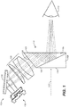
- Figure 1 shows an arrangement of optical components in one example of a thermal reflex sight 100.
- beam combiner 110 comprises a planar outer surface 105 oriented perpendicularly to a first axis 112, a planar outer surface 115 oriented parallel to and oppositely positioned from the planar outer surface 105, an internal planar surface 120 oriented at an acute angle with respect to the outer planar surfaces 105 and 115, and a planar outer surface 125.
- Internal planar surface 120 is coated with a partially reflective coating.
- the reflex sight comprises a digital display 130 for a digital camera (not shown).
- the reflex sight also comprises an afocal eyepiece 135.
- a first optical path through reflex sight 100 is coaxial with first axis 112 and provides to a user (e.g., user eye 113) a direct view in the visible spectrum straight through outer planar surfaces 105, 115 of the beam combiner of a target scene at which the aiming sight is aimed.
- the afocal eyepiece 135 collects visible light rays from digital camera display 130 to produce afocal light rays that are incident on and transmitted through planar outer surface 125 of the beam combiner.
- optional mirror 133 reflects the visible light rays from display 130 to afocal eyepiece 135, but other arrangements may be used instead if suitable.
- the afocal light rays from the eyepiece After passing through planar outer surface 125 of the beam combiner, the afocal light rays from the eyepiece are incident on planar outer surface 105 of the beam combiner from inside the beam combiner at an angle resulting in total internal reflection of the rays by planar outer surface 105 toward internal coated planar surface 120.
- the internal coated planar surface reflects the afocal light rays along the first axis as an afocal image of the target scene overlaying the direct view of the target scene with matched magnification.
- Light rays from display 130 are thus reflected twice in beam combiner 110, first by total internal reflection at planar outer surface 105, then by partially reflective coated surface 120. This arrangement allows beam combiner 110 to have an advantageously thin profile as measured along first axis 112.
- Display 130 may be or comprise, for example, a liquid crystal display (LCD) or an organic light emitting diode display (OLED).
- the reflex sight comprises an image intensifier rather than a digital camera. In that case display 130 is replaced by a phosphor screen at the output of the image intensifier.
- the partially reflective coating on internal planar surface 120 allows a portion of the visible spectrum to pass straight through beam combiner 110 parallel to first axis 112 to provide the direct view to the user.
- the partially reflective coating reflects a portion of the visible spectrum including wavelengths of light emitted by display 130 (or alternatively, emitted by the phosphor screen of an image intensifier) to overlay the image from the second optical path with the direct view.
- the partially reflective coating on internal planar surface 120 of the beam combiner is a narrow spectral band reflective coating and the light emitted by display 130 (or the phosphor screen of an image intensifier) is substantially monochromatic with a center wavelength closely coinciding with the center wavelength of the narrow band reflective coating such that the display light or phosphor screen light is substantially reflected (e.g., greater than or equal to 95%) toward the user's eye.
- the narrow band reflective coating on surface 120 is also known as a trichroic coating.
- Such a coating for example, can be designed to reflect a high proportion of light within a spectral band from 590 to 610 nm while transmitting a high proportion of visible light with wavelengths less than 590 nm and greater than 610 nm. This results in high display brightness reaching the user's eye while retaining high overall light transmission from the outside through the beam combiner to the user's eye.
- the partially reflective coating on internal planar surface 120 of the beam combiner is a short pass coating that is transmissive for visible wavelengths shorter than a cutoff wavelength and highly reflective for visible wavelengths longer than the cutoff wavelength.
- the cutoff wavelength may be, for example approximately 600 nm, approximately 610 nm, approximately 630 nm, or approximately 650 nm.
- the partially reflective coating on internal planar surface 120 may be selected to be highly reflective for a selected range of red light wavelengths and transmissive for shorter visible wavelengths. In such cases transmission of the full visible spectrum through the coated surface along first axis 112 (in the direct view) may be greater than or equal to about 85%, for example.
- the loss of red light from the direct view optical path as a result of reflection from coated surface 120 typically does not significantly degrade the direct view, because red light is less valuable to human vision than are the shorter visible wavelengths.
- Beam combiner 110 may be formed, for example, by bonding a Bauernfeind, Penta, or other prism 110a to a wedge prism 110b along internal surface (e.g., interface) 120.
- the presence of wedge prism 110b with outer planar surface 115 parallel to outer planar surface 105 provides an undistorted look-through for the direct view optical path.
- a digital camera providing a signal to display 130 may be sensitive to wavelengths in the ultraviolet spectral range of about 200 nm to about 400 nm, the visible spectral range of about 400 nm to about 700 nm, the near infrared spectral range of about 700 nm to about 1100 nm, or the short wave infrared spectral range of about 1100 nm to about 3000 nm.
- the digital camera detects light in the long wave infrared (LWIR) spectral range of about 7000 nm to about 12000 nm.
- the digital camera detects light in the mid wave infrared (MWIR) spectral range of about 3000 nm to about 5000 nm.
- LWIR long wave infrared
- MWIR mid wave infrared
- Digital cameras used in the invention may employ focal plane array technologies including, but not limited to, charge coupled device (CCD), complementary semiconductor oxide (CMOS), silicon (Si), indium gallium arsenide (InGaAs), indium antimonide (InSb), microbolometers, or mercury cadmium telluride (MCT or HgCdTe).
- CCD charge coupled device
- CMOS complementary semiconductor oxide
- Si silicon
- InGaAs indium gallium arsenide
- InSb indium antimonide
- MCT or HgCdTe mercury cadmium telluride
- Display 130 may be or comprise, for example, an 800x600, 15 micron pixel, OLED micro-display.
- Display 130 may be or comprise, for example, a 640x480, 15 micron pixel, LCD micro-display. Any other suitable digital display may also be used.
- An image intensifier if present, may be sensitive to light in the range of, for example, about 380 nm to about 900 nm.
- reflex sight 100 may have a field of view of, for example, about 16 degrees horizontally by about 12 degrees vertically (about 20 degrees diagonally).
- Figures 2A-2C show an example embodiment of thermal reflex sight 100 comprising a digital camera 150 integrated in a shared housing 160 with the components shown in Figure 1 .
- Figure 2A is a cross-sectional view showing the internal components.
- Figure 2B is a side view, and
- Figure 2C is a perspective view.
- Camera 150 comprises an objective lens assembly 153 that collects light along camera axis 154 and images it onto a focal plane array 155, which provides a signal representing the image to display 130.
- Camera axis 154 may be substantially parallel to first axis 112. Alternatively, camera axis 154 may intersect axis 112 at a distance from thermal reflex sight 100.
- Housing 150 may be adapted to mount to a firearm, for example via Picatinny rail mount 165.
- User interface controls such as rotatable knobs 170 and 175 and switches (buttons) 180A-180D may be used to adjust windage and elevation to align first axis 112 and camera axis 153 as desired with respect to the firearm on which the reflex sight is mounted and control the camera and/or camera display (or alternatively, an image intensifier if present).
- windage and elevation (more generally, bore sight alignment) adjustments may be made electronically by shifting the position on display 130 at which the image from camera 150 is displayed.
- thermal reflex sight 100 is about 115 mm, about 40 mm wide, and about 40 mm tall, with a direct view aperture of about 30 mm. Any other suitable dimensions may also be used.
- Figure 2D shows a cross-sectional view of an example embodiment of thermal reflex sight 100 comprising an image intensifier 151 (rather than a camera) integrated in a shared housing 160 with the components shown in Figure 1 .
- image intensifier 151 (rather than a camera) integrated in a shared housing 160 with the components shown in Figure 1 .
- objective lens assembly 153 collects light along image intensifier axis 154 and focuses it into image intensifier 151, which displays an intensified image on phosphor screen 131.
- Light rays from phosphor screen 131 are directed onto mirror 133 by prism 132, and thence through afocal eyepiece 135 and beam combiner 110.
- this embodiment of reflex sight 100 is similar or identical to that described above with respect to Figures 2A-2C .
- Figure 3A shows an example embodiment of thermal reflex sight 100 in which the components shown in Figure 1 are housed in a housing 185 adapted to attach (e.g., clip on) to a magnifying telescopic sight 190 with the direct view optical path through the reflex sight passing through the magnifying scope.
- reflex sight 100 is shown in cross-section, and magnifying scope 190 is shown in a corresponding side view.
- Scope 190 may provide a magnification of, for example, IX to 5X.
- Figure 3B shows a cross-sectional view of camera 150 housed separately from the components shown in Figure 1 in a housing 195, which may be attached for example to a side rail on a firearm to which magnifying scope 190 is mounted with camera axis 154 parallel to first axis 112, or with camera axis 154 intersecting first axis 112 at some distance.
- display 130 in thermal reflex sight 100 may be operated to present, for example, a low intensity image of the target scene, a full (e.g., thermal) image of the target scene, an outline image of (e.g., thermally) bright portions of the target scene, a mixed outline/low intensity image, or no image.
- Reflex sight 100 may be switched between these modes using buttons 180A-180D, for example.
- Figure 4A shows a direct view of a target scene (a person standing at the edge of a forest) without a fused (e.g., thermal) image
- Figure 4B shows an outline image of the same target scene fused with the direct view
- Figure 4C shows a full (e.g., thermal) image of the target scene fused with the direct view.
- Display 130 may also be operated to present a red dot, reticle, crosshair, or combination thereof in the fused image to provide a reference for where the firearm is aimed.
- reflex sight 100 is referred to herein as a "thermal" reflex sight, the term thermal is not meant to be limiting.
- Camera 150 or an image intensifier used in its place, may be selected to be sensitive to visible wavelengths of light or to wavelengths of light outside human vision other than, or in addition to, thermal infrared wavelengths.
- display 130 or the phosphor screen of an image intensifier, presents an image based at least in part on light collected at those other non-thermal wavelengths.
Landscapes
- Engineering & Computer Science (AREA)
- Physics & Mathematics (AREA)
- General Engineering & Computer Science (AREA)
- Optics & Photonics (AREA)
- Multimedia (AREA)
- Signal Processing (AREA)
- General Physics & Mathematics (AREA)
- Astronomy & Astrophysics (AREA)
- Telescopes (AREA)
- Studio Devices (AREA)
Claims (14)
- Viseur comprenant :un combineur de faisceaux (110) comprenant une première surface extérieure plane (105) orientée perpendiculairement à un premier axe (112), une deuxième surface extérieure plane (115) orientée parallèlement à la première surface extérieure plane (105) et positionnée à l'opposé de celle-ci, une surface interne plane revêtue orientée selon un angle aigu par rapport aux première et deuxième surfaces extérieures planes (105, 115), et une troisième surface extérieure plane (125) ;soit un intensificateur d'image (151) soit un affichage (130) pour un appareil photo numérique ;un oculaire afocal (135) ; etun premier boîtier (185) comprenant le combineur de faisceaux (110), l'intensificateur d'image (151) ou l'affichage (130) pour un appareil photo numérique, et l'oculaire afocal (135) ;dans lequel le boîtier (185) est conçu pour être fixé à une arme à feu ;dans lequel un premier chemin optique est coaxial au premier axe (112) ;caractérisé en ce que :le premier chemin optique fournit une vue directe dans le spectre visible directement à travers les première et deuxième surfaces extérieures planes (105, 115) du combineur de faisceaux (110) d'une scène cible vers laquelle le viseur est dirigé ;dans lequel, le long d'un second chemin optique, l'oculaire afocal (135) capte la lumière de l'intensificateur d'image (151) ou de l'affichage d'appareil photo numérique (130) pour produire des rayons lumineux afocaux qui sont incidents sur et transmis à travers la troisième surface extérieure plane (125) du combineur de faisceaux (110), puis incidents sur la première surface extérieure plane (105) du combineur de faisceaux (110) depuis l'intérieur du combineur de faisceaux (110) selon un angle produisant une réflexion interne totale des rayons par la première surface extérieure plane (105) vers la surface interne plane revêtue (120), puis réfléchis par la surface interne plane revêtue (120) le long du premier axe (112) en tant qu'image afocale de la scène cible superposée à la vue directe de la scène cible et dont le grossissement est adapté à celle-ci ;dans lequel la surface interne plane revêtue (120) est partiellement réfléchissante et configurée pour permettre à une partie du spectre visible de passer à travers le combineur de faisceaux (110), et configurée pour réfléchir une partie du spectre visible émis par l'intensificateur d'image (151) ou l'affichage (130).
- Viseur selon la revendication 1, comprenant un affichage d'appareil photo numérique (130), dans lequel le premier boîtier (185) comprend un appareil photo numérique connecté pour fournir un signal à l'affichage d'appareil photo numérique (130).
- Viseur selon la revendication 1, comprenant un affichage d'appareil photo numérique (130), dans lequel :un appareil photo numérique configuré pour fournir un signal à l'affichage d'appareil photo numérique (130) est logé dans un boîtier distinct (160) conçu pour être monté sur l'arme à feu ; etle premier boîtier (185) est conçu pour être fixé à une lunette de grossissement télescopique (190) d'arme à feu, le chemin optique à vue directe passant à travers la lunette de grossissement (190).
- Viseur selon la revendication 1, comprenant un intensificateur d'image (151).
- Viseur selon la revendication 1, comprenant un affichage d'appareil photo numérique (130) connecté pour recevoir un signal d'un appareil photo numérique, ou viseur selon la revendication 2, ou viseur selon la revendication 3, dans lequel l'affichage (130) peut être commandé pour fournir une image complète de la scène cible, une image de contours des parties lumineuses de la scène cible, ou un mélange d'une image complète et de contours de la scène cible.
- Viseur selon la revendication 1, comprenant un affichage d'appareil photo numérique (130) connecté pour recevoir un signal d'un appareil photo numérique, ou viseur selon la revendication 2, ou viseur selon la revendication 3, dans lequel l'affichage (130) peut être commandé pour superposer un point, un réticule, un réticule de pointage ou une combinaison de ceux-ci avec l'image afocale et une vue directe pour fournir une référence de la cible de l'arme à feu.
- Viseur selon la revendication 1, la revendication 5 ou la revendication 6, dans lequel un revêtement sur la surface interne plane revêtue (120) réfléchit la lumière visible ayant une longueur d'onde supérieure à une longueur d'onde de coupure et transmet de la lumière ayant une longueur d'onde plus courte qu'une longueur d'onde de coupure, et la lumière provenant de l'intensificateur d'image (151) ou de l'affichage d'appareil photo numérique (130) a une longueur d'onde supérieure à la longueur d'onde de coupure.
- Viseur selon la revendication 1, la revendication 5 ou la revendication 6, dans lequel un revêtement sur la surface interne plane revêtue (120) est un revêtement réfléchissant à bande spectrale étroite et la lumière émise par l'affichage d'appareil photo numérique (130) ou l'intensificateur d'image (151) est sensiblement monochromatique avec une longueur d'onde centrale coïncidant étroitement avec la longueur d'onde centrale du revêtement réfléchissant à bande étroite.
- Viseur selon la revendication 1, la revendication 7 ou la revendication 8, comprenant un affichage d'appareil photo numérique (130) connecté pour recevoir un signal d'un appareil photo numérique sensible à la lumière dans la gamme spectrale ultraviolette d'environ 200 nm à environ 400 nm.
- Viseur selon la revendication 1, la revendication 7 ou la revendication 8, comprenant un affichage d'appareil photo numérique (130) connecté pour recevoir un signal d'un appareil photo numérique sensible à la lumière dans la gamme spectrale visible d'environ 400 nm à environ 700 nm.
- Viseur selon la revendication 1, la revendication 7 ou la revendication 8, comprenant un affichage d'appareil photo numérique (130) connecté pour recevoir un signal d'un appareil photo numérique sensible à la lumière dans la gamme spectrale infrarouge proche d'environ 700 nm à environ 1 100 nm.
- Viseur selon la revendication 1, la revendication 7 ou la revendication 8, comprenant un affichage d'appareil photo numérique (130) connecté pour recevoir un signal d'un appareil photo numérique sensible à la lumière dans la gamme spectrale infrarouge de courte longueur d'onde d'environ 1 100 nm à environ 3 000 nm.
- Viseur selon la revendication 1, la revendication 7 ou la revendication 8, comprenant un affichage d'appareil photo numérique (130) connecté pour recevoir un signal d'un appareil photo numérique sensible à la lumière dans la gamme spectrale infrarouge de longueur d'onde moyenne (MWIR) d'environ 3 000 nm à environ 5 000 nm.
- Viseur selon la revendication 1, la revendication 7 ou la revendication 8, comprenant un affichage d'appareil photo numérique (130) connecté pour recevoir un signal d'un appareil photo numérique sensible à la lumière dans la gamme spectrale infrarouge de grande longueur d'onde (LWIR) d'environ 7 000 nm à environ 12 000 nm.
Priority Applications (1)
| Application Number | Priority Date | Filing Date | Title |
|---|---|---|---|
| EP21184531.8A EP3913315A3 (fr) | 2017-05-11 | 2018-05-11 | Viseur réflex thermique |
Applications Claiming Priority (1)
| Application Number | Priority Date | Filing Date | Title |
|---|---|---|---|
| US15/592,536 US10126099B1 (en) | 2017-05-11 | 2017-05-11 | Thermal reflex sight |
Related Child Applications (1)
| Application Number | Title | Priority Date | Filing Date |
|---|---|---|---|
| EP21184531.8A Division EP3913315A3 (fr) | 2017-05-11 | 2018-05-11 | Viseur réflex thermique |
Publications (2)
| Publication Number | Publication Date |
|---|---|
| EP3401631A1 EP3401631A1 (fr) | 2018-11-14 |
| EP3401631B1 true EP3401631B1 (fr) | 2021-07-21 |
Family
ID=62167129
Family Applications (2)
| Application Number | Title | Priority Date | Filing Date |
|---|---|---|---|
| EP21184531.8A Pending EP3913315A3 (fr) | 2017-05-11 | 2018-05-11 | Viseur réflex thermique |
| EP18171793.5A Active EP3401631B1 (fr) | 2017-05-11 | 2018-05-11 | Viseur réflex thermique |
Family Applications Before (1)
| Application Number | Title | Priority Date | Filing Date |
|---|---|---|---|
| EP21184531.8A Pending EP3913315A3 (fr) | 2017-05-11 | 2018-05-11 | Viseur réflex thermique |
Country Status (3)
| Country | Link |
|---|---|
| US (1) | US10126099B1 (fr) |
| EP (2) | EP3913315A3 (fr) |
| ES (1) | ES2890812T3 (fr) |
Families Citing this family (10)
| Publication number | Priority date | Publication date | Assignee | Title |
|---|---|---|---|---|
| FR3068776B1 (fr) | 2017-07-06 | 2020-10-02 | Thales Sa | Lunette de tir a viseur clair et camera thermique |
| CN111566433B (zh) | 2017-09-27 | 2023-03-07 | 布什内尔有限责任公司 | 热瞄准器 |
| RU191986U1 (ru) * | 2019-05-07 | 2019-08-29 | Акционерное общество "Вологодский оптико-механический завод" | Прицел-дальномер малогабаритный |
| US10663254B1 (en) * | 2019-06-12 | 2020-05-26 | Haim Refael Molcho | Illumination module for a handgun |
| US11473874B2 (en) | 2020-02-19 | 2022-10-18 | Maztech Industries, LLC | Weapon system with multi-function single-view scope |
| US11976901B2 (en) | 2021-06-07 | 2024-05-07 | Sturm, Ruger & Company, Inc. | Passively illuminated fiber optic reflex sights for firearms |
| WO2023023200A1 (fr) | 2021-08-18 | 2023-02-23 | Maztech Industries, LLC | Systèmes de visée d'arme |
| CN114251977A (zh) * | 2021-12-30 | 2022-03-29 | 合肥英睿系统技术有限公司 | 多光融合瞄准镜以及多光融合方法 |
| CN114994931B (zh) * | 2022-05-27 | 2023-08-01 | 合肥英睿系统技术有限公司 | 前置瞄准装置及组合式瞄准系统 |
| US20240027158A1 (en) * | 2022-07-20 | 2024-01-25 | Maia Pellegrini | Firearm firing control assembly and firearm optic positioning assembly |
Family Cites Families (25)
| Publication number | Priority date | Publication date | Assignee | Title |
|---|---|---|---|---|
| US6204961B1 (en) | 1995-09-18 | 2001-03-20 | Litton Systems, Inc. | Day and night sighting system |
| US6121600A (en) | 1997-07-28 | 2000-09-19 | Litton Systems, Inc. | Integrated night vision device and laser range finder |
| US5903996A (en) | 1997-08-01 | 1999-05-18 | Morley; Roland M. | Day/night viewing device with laser range finder utilizing two wavelengths of laser light, and method of its operation |
| US5901452A (en) * | 1997-08-29 | 1999-05-11 | Remington Arms Co., Inc. | Gunsight |
| US7057647B1 (en) | 2000-06-14 | 2006-06-06 | E-Watch, Inc. | Dual-mode camera system for day/night or variable zoom operation |
| US6020994A (en) | 1998-09-23 | 2000-02-01 | Raytheon Company | Integrated multifunctional multispectral sight assembly and method |
| US6781127B1 (en) | 2000-06-08 | 2004-08-24 | Equinox Corporation | Common aperture fused reflective/thermal emitted sensor and system |
| US7345277B2 (en) | 2000-08-09 | 2008-03-18 | Evan Zhang | Image intensifier and LWIR fusion/combination system |
| US6646799B1 (en) | 2000-08-30 | 2003-11-11 | Science Applications International Corporation | System and method for combining multiple energy bands to improve scene viewing |
| US7171776B2 (en) | 2004-03-10 | 2007-02-06 | Raytheon Company | Weapon sight having analog on-target indicators |
| US7307793B2 (en) | 2004-07-02 | 2007-12-11 | Insight Technology, Inc. | Fusion night vision system |
| US7051469B1 (en) | 2004-12-14 | 2006-05-30 | Omnitech Partners | Night sight for use with a telescopic sight |
| US7319557B2 (en) * | 2005-01-26 | 2008-01-15 | Eotech Acquisition Corporation | Fused thermal and direct view aiming sight |
| WO2007058675A2 (fr) * | 2005-05-27 | 2007-05-24 | Defense Holdings, Inc. | Illuminateur de viseur photoluminescent (pl) |
| US7333270B1 (en) | 2005-06-10 | 2008-02-19 | Omnitech Partners | Dual band night vision device |
| US7541581B2 (en) | 2005-10-18 | 2009-06-02 | Insight Technology Incorporated | Clip-on infrared imager |
| US7483213B2 (en) | 2006-03-24 | 2009-01-27 | Omnitech Partners | Image combining viewer |
| DE102007037389A1 (de) * | 2007-08-08 | 2009-02-19 | Carl Zeiss Ag | Visiervorrichtung |
| EP3270090B1 (fr) | 2010-08-04 | 2020-03-11 | Trijicon, Inc. | Optique fusionnee |
| US8970737B2 (en) | 2010-08-19 | 2015-03-03 | Omnitech Partners, Inc. | Apparatus and method for multi-spectral clip-on architecture |
| US9069172B1 (en) | 2010-09-15 | 2015-06-30 | Roland Morley | Multi-mode sight |
| US9057583B2 (en) | 2010-10-28 | 2015-06-16 | Surefire, Llc | Sight system |
| WO2014043142A1 (fr) * | 2012-09-11 | 2014-03-20 | Augmented Vision, Inc. | Appareil compact d'imagerie d'œil et de suivi d'œil |
| US9482803B2 (en) * | 2014-05-09 | 2016-11-01 | L-3 Communications, Warrior Systems Division, Eo Tech, Inc. | Integrated filter and grating in an aiming sight |
| EP3172524B1 (fr) * | 2014-07-22 | 2020-10-07 | N2 Imaging Systems, LLC | Combinaison de vidéo et de viseur optique |
-
2017
- 2017-05-11 US US15/592,536 patent/US10126099B1/en active Active
-
2018
- 2018-05-11 EP EP21184531.8A patent/EP3913315A3/fr active Pending
- 2018-05-11 EP EP18171793.5A patent/EP3401631B1/fr active Active
- 2018-05-11 ES ES18171793T patent/ES2890812T3/es active Active
Also Published As
| Publication number | Publication date |
|---|---|
| ES2890812T3 (es) | 2022-01-24 |
| EP3913315A3 (fr) | 2022-04-06 |
| US10126099B1 (en) | 2018-11-13 |
| EP3913315A2 (fr) | 2021-11-24 |
| EP3401631A1 (fr) | 2018-11-14 |
| US20180328694A1 (en) | 2018-11-15 |
Similar Documents
| Publication | Publication Date | Title |
|---|---|---|
| EP3401631B1 (fr) | Viseur réflex thermique | |
| US7911687B2 (en) | Sighted device operable in visible-wavelength or electro-optical/visible-wavelength sighting modes | |
| US7483213B2 (en) | Image combining viewer | |
| US7755047B2 (en) | Clip-on infrared imager | |
| US9323061B2 (en) | Viewer with display overlay | |
| US9148579B1 (en) | Fusion night vision system | |
| US7158296B1 (en) | Vision system with eye dominance forced to fusion channel | |
| EP3004958B1 (fr) | Configuration optique d'un système compact intégré de visualisation jour/nuit et de télémètre laser | |
| US20120007987A1 (en) | Optical system with automatic switching between operation in daylight and thermovision modes | |
| JP7393951B2 (ja) | 照光照準器及び熱撮像カメラを有する照準スコープ | |
| US20120019700A1 (en) | Optical system with automatic mixing of daylight and thermal vision digital video signals | |
| US7746551B2 (en) | Vision system with eye dominance forced to fusion channel | |
| KR20150023265A (ko) | 디스플레이 오버레이를 갖춘 뷰어 | |
| US11206341B2 (en) | Fusion night vision system | |
| US20080011941A1 (en) | Aviation night vision system using common aperture and multi-spectral image fusion | |
| Gerken et al. | Military reconnaissance platform for the spectral range from the visible to the MWIR | |
| US8860831B1 (en) | Brightness tracking light sensor | |
| US12078793B2 (en) | Weapon sight systems | |
| FR2963440A1 (fr) | Systeme de visualisation nocturne modulaire a fusion optique | |
| US9426389B1 (en) | Second imaging device adaptable for use with first imaging device and method for using same | |
| US20200404194A1 (en) | Reflex sight incorporating an infrared camera | |
| Bergeron et al. | Dual-band dual field-of-view TVWS prototype |
Legal Events
| Date | Code | Title | Description |
|---|---|---|---|
| PUAI | Public reference made under article 153(3) epc to a published international application that has entered the european phase |
Free format text: ORIGINAL CODE: 0009012 |
|
| STAA | Information on the status of an ep patent application or granted ep patent |
Free format text: STATUS: THE APPLICATION HAS BEEN PUBLISHED |
|
| AK | Designated contracting states |
Kind code of ref document: A1 Designated state(s): AL AT BE BG CH CY CZ DE DK EE ES FI FR GB GR HR HU IE IS IT LI LT LU LV MC MK MT NL NO PL PT RO RS SE SI SK SM TR |
|
| AX | Request for extension of the european patent |
Extension state: BA ME |
|
| STAA | Information on the status of an ep patent application or granted ep patent |
Free format text: STATUS: REQUEST FOR EXAMINATION WAS MADE |
|
| 17P | Request for examination filed |
Effective date: 20190514 |
|
| RBV | Designated contracting states (corrected) |
Designated state(s): AL AT BE BG CH CY CZ DE DK EE ES FI FR GB GR HR HU IE IS IT LI LT LU LV MC MK MT NL NO PL PT RO RS SE SI SK SM TR |
|
| GRAP | Despatch of communication of intention to grant a patent |
Free format text: ORIGINAL CODE: EPIDOSNIGR1 |
|
| STAA | Information on the status of an ep patent application or granted ep patent |
Free format text: STATUS: GRANT OF PATENT IS INTENDED |
|
| RIC1 | Information provided on ipc code assigned before grant |
Ipc: F41G 3/16 20060101ALI20210122BHEP Ipc: F41G 1/32 20060101AFI20210122BHEP Ipc: F41G 3/32 20060101ALI20210122BHEP Ipc: F41G 1/387 20060101ALI20210122BHEP |
|
| INTG | Intention to grant announced |
Effective date: 20210210 |
|
| GRAS | Grant fee paid |
Free format text: ORIGINAL CODE: EPIDOSNIGR3 |
|
| GRAA | (expected) grant |
Free format text: ORIGINAL CODE: 0009210 |
|
| STAA | Information on the status of an ep patent application or granted ep patent |
Free format text: STATUS: THE PATENT HAS BEEN GRANTED |
|
| AK | Designated contracting states |
Kind code of ref document: B1 Designated state(s): AL AT BE BG CH CY CZ DE DK EE ES FI FR GB GR HR HU IE IS IT LI LT LU LV MC MK MT NL NO PL PT RO RS SE SI SK SM TR |
|
| REG | Reference to a national code |
Ref country code: GB Ref legal event code: FG4D |
|
| REG | Reference to a national code |
Ref country code: CH Ref legal event code: EP |
|
| REG | Reference to a national code |
Ref country code: DE Ref legal event code: R096 Ref document number: 602018020294 Country of ref document: DE |
|
| REG | Reference to a national code |
Ref country code: AT Ref legal event code: REF Ref document number: 1412968 Country of ref document: AT Kind code of ref document: T Effective date: 20210815 |
|
| REG | Reference to a national code |
Ref country code: IE Ref legal event code: FG4D |
|
| REG | Reference to a national code |
Ref country code: SE Ref legal event code: TRGR |
|
| REG | Reference to a national code |
Ref country code: LT Ref legal event code: MG9D |
|
| REG | Reference to a national code |
Ref country code: NL Ref legal event code: MP Effective date: 20210721 |
|
| REG | Reference to a national code |
Ref country code: AT Ref legal event code: MK05 Ref document number: 1412968 Country of ref document: AT Kind code of ref document: T Effective date: 20210721 |
|
| REG | Reference to a national code |
Ref country code: ES Ref legal event code: FG2A Ref document number: 2890812 Country of ref document: ES Kind code of ref document: T3 Effective date: 20220124 |
|
| PG25 | Lapsed in a contracting state [announced via postgrant information from national office to epo] |
Ref country code: RS Free format text: LAPSE BECAUSE OF FAILURE TO SUBMIT A TRANSLATION OF THE DESCRIPTION OR TO PAY THE FEE WITHIN THE PRESCRIBED TIME-LIMIT Effective date: 20210721 Ref country code: HR Free format text: LAPSE BECAUSE OF FAILURE TO SUBMIT A TRANSLATION OF THE DESCRIPTION OR TO PAY THE FEE WITHIN THE PRESCRIBED TIME-LIMIT Effective date: 20210721 Ref country code: FI Free format text: LAPSE BECAUSE OF FAILURE TO SUBMIT A TRANSLATION OF THE DESCRIPTION OR TO PAY THE FEE WITHIN THE PRESCRIBED TIME-LIMIT Effective date: 20210721 Ref country code: NO Free format text: LAPSE BECAUSE OF FAILURE TO SUBMIT A TRANSLATION OF THE DESCRIPTION OR TO PAY THE FEE WITHIN THE PRESCRIBED TIME-LIMIT Effective date: 20211021 Ref country code: PT Free format text: LAPSE BECAUSE OF FAILURE TO SUBMIT A TRANSLATION OF THE DESCRIPTION OR TO PAY THE FEE WITHIN THE PRESCRIBED TIME-LIMIT Effective date: 20211122 Ref country code: NL Free format text: LAPSE BECAUSE OF FAILURE TO SUBMIT A TRANSLATION OF THE DESCRIPTION OR TO PAY THE FEE WITHIN THE PRESCRIBED TIME-LIMIT Effective date: 20210721 Ref country code: AT Free format text: LAPSE BECAUSE OF FAILURE TO SUBMIT A TRANSLATION OF THE DESCRIPTION OR TO PAY THE FEE WITHIN THE PRESCRIBED TIME-LIMIT Effective date: 20210721 Ref country code: BG Free format text: LAPSE BECAUSE OF FAILURE TO SUBMIT A TRANSLATION OF THE DESCRIPTION OR TO PAY THE FEE WITHIN THE PRESCRIBED TIME-LIMIT Effective date: 20211021 Ref country code: LT Free format text: LAPSE BECAUSE OF FAILURE TO SUBMIT A TRANSLATION OF THE DESCRIPTION OR TO PAY THE FEE WITHIN THE PRESCRIBED TIME-LIMIT Effective date: 20210721 |
|
| PG25 | Lapsed in a contracting state [announced via postgrant information from national office to epo] |
Ref country code: PL Free format text: LAPSE BECAUSE OF FAILURE TO SUBMIT A TRANSLATION OF THE DESCRIPTION OR TO PAY THE FEE WITHIN THE PRESCRIBED TIME-LIMIT Effective date: 20210721 Ref country code: LV Free format text: LAPSE BECAUSE OF FAILURE TO SUBMIT A TRANSLATION OF THE DESCRIPTION OR TO PAY THE FEE WITHIN THE PRESCRIBED TIME-LIMIT Effective date: 20210721 Ref country code: GR Free format text: LAPSE BECAUSE OF FAILURE TO SUBMIT A TRANSLATION OF THE DESCRIPTION OR TO PAY THE FEE WITHIN THE PRESCRIBED TIME-LIMIT Effective date: 20211022 |
|
| REG | Reference to a national code |
Ref country code: DE Ref legal event code: R097 Ref document number: 602018020294 Country of ref document: DE |
|
| PG25 | Lapsed in a contracting state [announced via postgrant information from national office to epo] |
Ref country code: DK Free format text: LAPSE BECAUSE OF FAILURE TO SUBMIT A TRANSLATION OF THE DESCRIPTION OR TO PAY THE FEE WITHIN THE PRESCRIBED TIME-LIMIT Effective date: 20210721 |
|
| PLBE | No opposition filed within time limit |
Free format text: ORIGINAL CODE: 0009261 |
|
| STAA | Information on the status of an ep patent application or granted ep patent |
Free format text: STATUS: NO OPPOSITION FILED WITHIN TIME LIMIT |
|
| PG25 | Lapsed in a contracting state [announced via postgrant information from national office to epo] |
Ref country code: SM Free format text: LAPSE BECAUSE OF FAILURE TO SUBMIT A TRANSLATION OF THE DESCRIPTION OR TO PAY THE FEE WITHIN THE PRESCRIBED TIME-LIMIT Effective date: 20210721 Ref country code: SK Free format text: LAPSE BECAUSE OF FAILURE TO SUBMIT A TRANSLATION OF THE DESCRIPTION OR TO PAY THE FEE WITHIN THE PRESCRIBED TIME-LIMIT Effective date: 20210721 Ref country code: RO Free format text: LAPSE BECAUSE OF FAILURE TO SUBMIT A TRANSLATION OF THE DESCRIPTION OR TO PAY THE FEE WITHIN THE PRESCRIBED TIME-LIMIT Effective date: 20210721 Ref country code: EE Free format text: LAPSE BECAUSE OF FAILURE TO SUBMIT A TRANSLATION OF THE DESCRIPTION OR TO PAY THE FEE WITHIN THE PRESCRIBED TIME-LIMIT Effective date: 20210721 Ref country code: AL Free format text: LAPSE BECAUSE OF FAILURE TO SUBMIT A TRANSLATION OF THE DESCRIPTION OR TO PAY THE FEE WITHIN THE PRESCRIBED TIME-LIMIT Effective date: 20210721 |
|
| 26N | No opposition filed |
Effective date: 20220422 |
|
| REG | Reference to a national code |
Ref country code: CH Ref legal event code: PL |
|
| REG | Reference to a national code |
Ref country code: BE Ref legal event code: MM Effective date: 20220531 |
|
| PG25 | Lapsed in a contracting state [announced via postgrant information from national office to epo] |
Ref country code: MC Free format text: LAPSE BECAUSE OF FAILURE TO SUBMIT A TRANSLATION OF THE DESCRIPTION OR TO PAY THE FEE WITHIN THE PRESCRIBED TIME-LIMIT Effective date: 20210721 Ref country code: LU Free format text: LAPSE BECAUSE OF NON-PAYMENT OF DUE FEES Effective date: 20220511 Ref country code: LI Free format text: LAPSE BECAUSE OF NON-PAYMENT OF DUE FEES Effective date: 20220531 Ref country code: CH Free format text: LAPSE BECAUSE OF NON-PAYMENT OF DUE FEES Effective date: 20220531 |
|
| PG25 | Lapsed in a contracting state [announced via postgrant information from national office to epo] |
Ref country code: IE Free format text: LAPSE BECAUSE OF NON-PAYMENT OF DUE FEES Effective date: 20220511 |
|
| PG25 | Lapsed in a contracting state [announced via postgrant information from national office to epo] |
Ref country code: BE Free format text: LAPSE BECAUSE OF NON-PAYMENT OF DUE FEES Effective date: 20220531 |
|
| P01 | Opt-out of the competence of the unified patent court (upc) registered |
Effective date: 20230516 |
|
| PG25 | Lapsed in a contracting state [announced via postgrant information from national office to epo] |
Ref country code: HU Free format text: LAPSE BECAUSE OF FAILURE TO SUBMIT A TRANSLATION OF THE DESCRIPTION OR TO PAY THE FEE WITHIN THE PRESCRIBED TIME-LIMIT; INVALID AB INITIO Effective date: 20180511 |
|
| PG25 | Lapsed in a contracting state [announced via postgrant information from national office to epo] |
Ref country code: MK Free format text: LAPSE BECAUSE OF FAILURE TO SUBMIT A TRANSLATION OF THE DESCRIPTION OR TO PAY THE FEE WITHIN THE PRESCRIBED TIME-LIMIT Effective date: 20210721 Ref country code: CY Free format text: LAPSE BECAUSE OF FAILURE TO SUBMIT A TRANSLATION OF THE DESCRIPTION OR TO PAY THE FEE WITHIN THE PRESCRIBED TIME-LIMIT Effective date: 20210721 |
|
| PG25 | Lapsed in a contracting state [announced via postgrant information from national office to epo] |
Ref country code: TR Free format text: LAPSE BECAUSE OF FAILURE TO SUBMIT A TRANSLATION OF THE DESCRIPTION OR TO PAY THE FEE WITHIN THE PRESCRIBED TIME-LIMIT Effective date: 20210721 |
|
| PGFP | Annual fee paid to national office [announced via postgrant information from national office to epo] |
Ref country code: GB Payment date: 20240522 Year of fee payment: 7 |
|
| PGFP | Annual fee paid to national office [announced via postgrant information from national office to epo] |
Ref country code: DE Payment date: 20240522 Year of fee payment: 7 |
|
| PGFP | Annual fee paid to national office [announced via postgrant information from national office to epo] |
Ref country code: ES Payment date: 20240614 Year of fee payment: 7 |
|
| PGFP | Annual fee paid to national office [announced via postgrant information from national office to epo] |
Ref country code: CZ Payment date: 20240430 Year of fee payment: 7 |
|
| PGFP | Annual fee paid to national office [announced via postgrant information from national office to epo] |
Ref country code: FR Payment date: 20240522 Year of fee payment: 7 |
|
| PGFP | Annual fee paid to national office [announced via postgrant information from national office to epo] |
Ref country code: SE Payment date: 20240522 Year of fee payment: 7 |
|
| PG25 | Lapsed in a contracting state [announced via postgrant information from national office to epo] |
Ref country code: MT Free format text: LAPSE BECAUSE OF FAILURE TO SUBMIT A TRANSLATION OF THE DESCRIPTION OR TO PAY THE FEE WITHIN THE PRESCRIBED TIME-LIMIT Effective date: 20210721 |
|
| PGFP | Annual fee paid to national office [announced via postgrant information from national office to epo] |
Ref country code: IT Payment date: 20240531 Year of fee payment: 7 |