EP3401577A1 - Dichteinheit mit einer tellerfeder und ventilanordnung mit einer solchen dichteinheit - Google Patents
Dichteinheit mit einer tellerfeder und ventilanordnung mit einer solchen dichteinheit Download PDFInfo
- Publication number
- EP3401577A1 EP3401577A1 EP18169138.7A EP18169138A EP3401577A1 EP 3401577 A1 EP3401577 A1 EP 3401577A1 EP 18169138 A EP18169138 A EP 18169138A EP 3401577 A1 EP3401577 A1 EP 3401577A1
- Authority
- EP
- European Patent Office
- Prior art keywords
- sealing
- plate spring
- sealing unit
- fluid channel
- spring
- Prior art date
- Legal status (The legal status is an assumption and is not a legal conclusion. Google has not performed a legal analysis and makes no representation as to the accuracy of the status listed.)
- Granted
Links
Images

Classifications
-
- F—MECHANICAL ENGINEERING; LIGHTING; HEATING; WEAPONS; BLASTING
- F16—ENGINEERING ELEMENTS AND UNITS; GENERAL MEASURES FOR PRODUCING AND MAINTAINING EFFECTIVE FUNCTIONING OF MACHINES OR INSTALLATIONS; THERMAL INSULATION IN GENERAL
- F16K—VALVES; TAPS; COCKS; ACTUATING-FLOATS; DEVICES FOR VENTING OR AERATING
- F16K5/00—Plug valves; Taps or cocks comprising only cut-off apparatus having at least one of the sealing faces shaped as a more or less complete surface of a solid of revolution, the opening and closing movement being predominantly rotary
- F16K5/04—Plug valves; Taps or cocks comprising only cut-off apparatus having at least one of the sealing faces shaped as a more or less complete surface of a solid of revolution, the opening and closing movement being predominantly rotary with plugs having cylindrical surfaces; Packings therefor
- F16K5/0457—Packings
- F16K5/0464—Packings in the housing
-
- F—MECHANICAL ENGINEERING; LIGHTING; HEATING; WEAPONS; BLASTING
- F16—ENGINEERING ELEMENTS AND UNITS; GENERAL MEASURES FOR PRODUCING AND MAINTAINING EFFECTIVE FUNCTIONING OF MACHINES OR INSTALLATIONS; THERMAL INSULATION IN GENERAL
- F16K—VALVES; TAPS; COCKS; ACTUATING-FLOATS; DEVICES FOR VENTING OR AERATING
- F16K5/00—Plug valves; Taps or cocks comprising only cut-off apparatus having at least one of the sealing faces shaped as a more or less complete surface of a solid of revolution, the opening and closing movement being predominantly rotary
- F16K5/06—Plug valves; Taps or cocks comprising only cut-off apparatus having at least one of the sealing faces shaped as a more or less complete surface of a solid of revolution, the opening and closing movement being predominantly rotary with plugs having spherical surfaces; Packings therefor
- F16K5/0663—Packings
- F16K5/0689—Packings between housing and plug
-
- F—MECHANICAL ENGINEERING; LIGHTING; HEATING; WEAPONS; BLASTING
- F16—ENGINEERING ELEMENTS AND UNITS; GENERAL MEASURES FOR PRODUCING AND MAINTAINING EFFECTIVE FUNCTIONING OF MACHINES OR INSTALLATIONS; THERMAL INSULATION IN GENERAL
- F16J—PISTONS; CYLINDERS; SEALINGS
- F16J15/00—Sealings
- F16J15/02—Sealings between relatively-stationary surfaces
- F16J15/06—Sealings between relatively-stationary surfaces with solid packing compressed between sealing surfaces
- F16J15/08—Sealings between relatively-stationary surfaces with solid packing compressed between sealing surfaces with exclusively metal packing
- F16J15/0887—Sealings between relatively-stationary surfaces with solid packing compressed between sealing surfaces with exclusively metal packing the sealing effect being obtained by elastic deformation of the packing
-
- F—MECHANICAL ENGINEERING; LIGHTING; HEATING; WEAPONS; BLASTING
- F16—ENGINEERING ELEMENTS AND UNITS; GENERAL MEASURES FOR PRODUCING AND MAINTAINING EFFECTIVE FUNCTIONING OF MACHINES OR INSTALLATIONS; THERMAL INSULATION IN GENERAL
- F16K—VALVES; TAPS; COCKS; ACTUATING-FLOATS; DEVICES FOR VENTING OR AERATING
- F16K1/00—Lift valves or globe valves, i.e. cut-off apparatus with closure members having at least a component of their opening and closing motion perpendicular to the closing faces
- F16K1/16—Lift valves or globe valves, i.e. cut-off apparatus with closure members having at least a component of their opening and closing motion perpendicular to the closing faces with pivoted closure-members
- F16K1/18—Lift valves or globe valves, i.e. cut-off apparatus with closure members having at least a component of their opening and closing motion perpendicular to the closing faces with pivoted closure-members with pivoted discs or flaps
- F16K1/22—Lift valves or globe valves, i.e. cut-off apparatus with closure members having at least a component of their opening and closing motion perpendicular to the closing faces with pivoted closure-members with pivoted discs or flaps with axis of rotation crossing the valve member, e.g. butterfly valves
- F16K1/226—Shaping or arrangements of the sealing
- F16K1/2263—Shaping or arrangements of the sealing the sealing being arranged on the valve seat
- F16K1/2266—Shaping or arrangements of the sealing the sealing being arranged on the valve seat and being forced into sealing contact with the valve member by a spring or a spring-like member
-
- F—MECHANICAL ENGINEERING; LIGHTING; HEATING; WEAPONS; BLASTING
- F16—ENGINEERING ELEMENTS AND UNITS; GENERAL MEASURES FOR PRODUCING AND MAINTAINING EFFECTIVE FUNCTIONING OF MACHINES OR INSTALLATIONS; THERMAL INSULATION IN GENERAL
- F16K—VALVES; TAPS; COCKS; ACTUATING-FLOATS; DEVICES FOR VENTING OR AERATING
- F16K5/00—Plug valves; Taps or cocks comprising only cut-off apparatus having at least one of the sealing faces shaped as a more or less complete surface of a solid of revolution, the opening and closing movement being predominantly rotary
- F16K5/06—Plug valves; Taps or cocks comprising only cut-off apparatus having at least one of the sealing faces shaped as a more or less complete surface of a solid of revolution, the opening and closing movement being predominantly rotary with plugs having spherical surfaces; Packings therefor
- F16K5/0663—Packings
- F16K5/0673—Composite packings
- F16K5/0678—Composite packings in which only one of the components of the composite packing is contacting the plug
-
- F—MECHANICAL ENGINEERING; LIGHTING; HEATING; WEAPONS; BLASTING
- F16—ENGINEERING ELEMENTS AND UNITS; GENERAL MEASURES FOR PRODUCING AND MAINTAINING EFFECTIVE FUNCTIONING OF MACHINES OR INSTALLATIONS; THERMAL INSULATION IN GENERAL
- F16K—VALVES; TAPS; COCKS; ACTUATING-FLOATS; DEVICES FOR VENTING OR AERATING
- F16K5/00—Plug valves; Taps or cocks comprising only cut-off apparatus having at least one of the sealing faces shaped as a more or less complete surface of a solid of revolution, the opening and closing movement being predominantly rotary
- F16K5/08—Details
- F16K5/14—Special arrangements for separating the sealing faces or for pressing them together
- F16K5/20—Special arrangements for separating the sealing faces or for pressing them together for plugs with spherical surfaces
- F16K5/201—Special arrangements for separating the sealing faces or for pressing them together for plugs with spherical surfaces with the housing or parts of the housing mechanically pressing the seal against the plug
Definitions
- the invention relates to a sealing unit for sealing a transition between a valve member and one end of a fluid channel. Furthermore, the invention relates to a valve arrangement with such a sealing unit.
- valve assemblies include an adjustable valve member, such as a rotary valve, which in a first valve position releases a passage between a fluid supply channel and a first fluid discharge channel and, in a second valve position, releases a passage between the fluid supply channel and a second fluid discharge channel. Also intermediate positions of the valve member are possible, for example. To be able to set an optimal coolant temperature.
- a sealing unit which is suitable for sealing a transition between one end of a fluid channel and a valve member.
- the sealing unit has two sealing sleeve parts which overlap one another at least in sections and are arranged so as to be movable relative to one another in the axial direction, which have a sealing gap running in the axial direction between them.
- the sealing gap is formed by the sealing contact of a cylindrical Inner surface of the one sealing sleeve part formed on a cylindrical outer surface of the other sealing sleeve part.
- the two sealing sleeve parts are urged apart in the axial direction by means of a corrugated annular spring in order to seal against the end of the fluid channel or of the valve member.
- the invention has for its object to provide a sealing unit, which has a low complexity and at the same time a good sealing effect. Furthermore, it is an object to provide a valve arrangement with such a sealing unit.
- a sealing unit for sealing a transition between a valve member and an end of a fluid channel.
- the sealing unit has a sealing ring for sealing against the valve member, and a plate spring for sealing against the end of the fluid channel.
- the sealing ring and the plate spring are sealingly connected.
- the sealing unit has only a few components, it is comparatively less complex in design.
- the sealing unit can only consist of the sealing ring and the plate spring.
- the production or assembly of the sealing unit is easy to implement and thus cheap.
- the requirement for the dimensional accuracy of the individual components is lower than in the conventional sealing unit described above.
- the sealing unit has a plate spring.
- the diaphragm spring is to be understood in particular to mean a spring which has a flexurally soft plate.
- the flexible plate is bent according to the desired shape of the plate spring.
- the outer portion of the plate spring serves to seal against the end of the fluid channel.
- the inner region of the diaphragm spring is sealingly connected to the sealing ring. It means sealingly connected that no fluid, in particular no liquid, can penetrate between the plate spring and the sealing ring. A leakage between the diaphragm spring and sealing ring is thus prevented.
- the diaphragm spring may comprise a metal, a stainless steel and / or a plastic.
- the sealing ring is pressed sealingly against the valve member via the diaphragm spring.
- the use of a metallic plate spring ensures consistent spring properties over the entire lifetime of the sealing unit.
- the contact pressure which causes the diaphragm spring, and thus also the sealing effect caused by the contact pressure, remains constant over time. Temperature fluctuations or the fluid used do not affect the spring action of the diaphragm spring.
- the sealing ring has a plastic.
- the plastic is polyvinylidene fluoride (PVDF) or polytetrafluoroethylene (PTFE).
- PVDF polyvinylidene fluoride
- PTFE polytetrafluoroethylene
- the valve member is a control element for controlling a fluid circuit. By turning the valve member, the flow of a fluid flow to or from a fluid channel can be controlled. Further, the end of the fluid channel may be formed in a housing.
- the sealing unit is rotationally symmetrical about a central axis.
- the sealing ring is formed circular cylindrical. This results in a circular contact region of the sealing ring, which can suitably seal a spherical region of the valve member.
- the rotationally symmetrical plate spring can suitably seal the end of a cylindrical fluid channel.
- the plate spring has an inner end region.
- the plate spring is connected to the inner end region cohesively, non-positively and / or positively connected to the sealing ring.
- the plate spring and the sealing ring are sealingly connected to each other, so that no fluid, in particular no liquid, can flow between the plate spring and the sealing ring.
- the plate spring and the sealing ring are integrally connected to one another, then the plate spring and the sealing ring are firmly connected to each other by a spray.
- the sealing ring can be made so that it is intimately connected to the plate spring.
- the plate spring and the sealing ring are formed so that they engage with each other to realize a sealing connection.
- the diameter of an opening which is formed by the inner region of the plate spring is equal to or slightly smaller than the diameter of the sealing ring. This creates a sealing connection between disc spring and sealing ring.
- the plate spring may have an outer end portion, wherein the outer end portion is directed away from the sealing ring.
- the plate spring can be made rather flat overall and thus easy to manufacture.
- the plate spring may be bent over and have an outer end region, wherein the outer end region is directed to the sealing ring.
- the plate spring has circumferential annular waves or circumferential spiral waves. About this circumferential annular or spiral waves of the plate spring and the thickness of the plate spring, the desired bending stiffness of the plate spring can be adjusted. On the flexural rigidity then determines the Zustellkraft with which the plate spring presses against the end of the fluid channel and / or with which the plate spring presses the sealing ring against the valve member.
- the plate spring is very thin.
- the plate spring has a thickness of a few tenths of a millimeter.
- the thickness of the diaphragm spring may be in the range of 0.01 mm to 2 mm, preferably in the range of 0.05 mm to 1 mm, and more preferably in the range of 0.1 mm to 0.5 mm.
- the sealing unit may have at least one O-ring for influencing the spring action of the plate spring.
- the O-ring may be an elastomeric element.
- the O-ring is positioned in particular in the spring travel of the plate spring in order to influence the spring action of the plate spring and / or to limit the spring travel of the plate spring.
- the plate spring has an elastic enclosure for improving the sealing effect relative to the end of the fluid channel.
- the elastic enclosure may be a sealing lacquer.
- valve assembly which is in particular a control valve for controlling a coolant circuit, provided with a sealing unit, as described, one end of a fluid channel and a valve member.
- the plate spring can rest on an outer region of the end of the fluid channel.
- the plate spring may be clamped within the end of the fluid channel.
- the end of the fluid channel does not need to be specially designed, since the form of the end of the fluid channel does not matter.
- the plate spring lies more or less flat with its outer end region on the outer region of the end of the fluid channel.
- the end of the fluid channel is formed by a region of a housing.
- the disc spring When the disc spring is clamped within the end of the fluid channel, then the disc spring seals the sealing unit against a wall of the fluid channel.
- the contact pressure exerted by the disc spring on the wall of the fluid channel not correlated with the force exerted by the sealing ring on the valve member.
- the contact pressure which ensures the tightness between the diaphragm spring and the wall of the end of the fluid channel, can therefore be chosen arbitrarily large in this case.
- the end of the fluid channel may have a recess.
- the diaphragm spring then exerts a pressure against the wall of the recess and thereby seals against the wall of the recess.
- the end of the fluid channel is formed with the recess of a portion of a housing.
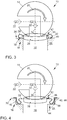
- Fig. 1 shows a schematic and partial perspective view of a valve assembly 10 with a sealing unit 12 according to an embodiment of the invention.
- the valve assembly 10 further includes a valve member 14 and an end 16 of a fluid channel 18.
- the valve member 14 is rotatable in the direction of the arrow 20 to control the flow of a coolant.
- the coolant flows in the direction of the arrows 22.
- the sealing unit 12 serves to seal the transition between the valve member 14 and the end 16 of the fluid channel 18.
- the end 16 of the fluid channel 18 is formed in a region of a housing 24.
- the sealing unit 12 has a sealing ring 26 and a plate spring 28.
- the sealing ring 26 seals the sealing unit 12 from the valve member 14.
- the plate spring 28 seals the sealing unit 12 from the end 16 of the fluid channel 18 from.
- the sealing ring 26 and the plate spring 28 are sealingly connected to each other, so that there is no leakage of coolant between the sealing ring 26 and plate spring 28.
- FIG. 1 shows, an outer end portion 32 of the plate spring 28 on an outer portion 30 of the end 16 of the fluid channel 18.
- the outer end region 32 seals the sealing unit 12 from the outer region 30. Further, the outer end portion 32 is directed away from the sealing ring 26.
- the sealing unit 12 is rotationally symmetrical about a central axis 34.
- the sealing ring 26 has a circular cylindrical shape. Accordingly, there is a circular contact surface towards the valve member 14, which is suitable for sealing the sealing ring 26 against a spherical shape of the valve member 14.
- the plate spring 28 is therefore also rotationally symmetrical.
- the plate spring 28 has an inner end region 36.
- the plate spring 28 is integrally connected to the inner end region 36 with the sealing ring 26. More specifically, the inner end portion 36 of the plate spring 28 is intimately connected to the sealing ring 26 by an encapsulation. A leakage between the plate spring 28 and sealing ring 26 is thus prevented.
- the production of the sealing unit 12 succeeds without installation effort. As a result, errors in the production of the sealing unit 12 can be avoided. Furthermore, a saving of costs can be achieved.
- the inner end portion 36 of the plate spring 28 may be positively connected to the sealing ring 26.
- the plate spring 28 engages in a recess of the sealing ring 26. The plate spring 28 is then mounted gap-free on the sealing ring 26.
- the inner end region 36 of the disk spring 28 can be connected in a force-locking manner to the sealing ring 26.
- the plate spring 28 is mounted without gaps on the sealing ring 26.
- the sealing unit 12 has an O-ring 38.
- the O-ring 38 may be formed as an elastomeric element.
- the O-ring 38 is used to set or limit the spring action of the plate spring 28.
- the O-ring 38 is positioned in the spring travel of the plate spring 28.
- a plurality of O-rings 38 may be provided.
- the plate spring 28 has an elastic enclosure 40.
- the elastic enclosure 40 serves to improve the sealing effect of the plate spring 28 with respect to the end 16 of the fluid channel 18.
- the elastic enclosure 40 on the underside of the plate spring 28, which faces in the direction of the fluid channel 18, is arranged.
- the elastic enclosure 40 is then pressed due to the spring action of the plate spring 28 against the outer region 30 of the end 16 of the fluid channel 18. As a result, infiltration of the plate spring 28 can be prevented with coolant.
- Fig. 2 shows a plan view of the sealing unit 12 from Fig. 1
- the sealing ring 26 is made of plastic. These may in particular be the plastics polyvinylidene fluoride (PVDF) or polytetrafluoroethylene (PTFE).
- PVDF polyvinylidene fluoride
- PTFE polytetrafluoroethylene
- the plate spring 28 however, has a metal or stainless steel. Alternatively, the plate spring 28 may also be made of plastic.
- the plate spring 28 is made very thin with a thickness of a few tenths of a millimeter. In this case, the plate spring 28 is formed as a flexurally soft plate. Next, the plate spring 28 has circumferential annular shafts 42. About the thickness of the plate spring 28 and the exact shape and number of rotating annular shafts 42, the desired bending stiffness of the plate spring 28 is adjusted. The bending stiffness of the plate spring 28 in turn determines the contact pressure with which the plate spring is pressed onto the outer region 30 of the end 16 of the fluid channel 18 and with which the sealing ring 26 is pressed onto the valve member 14.
- the plate spring 28 instead of the circumferential annular shafts 42 also have circumferential spiral waves.
- Fig. 3 shows a schematic and partial perspective view of a valve assembly 10 with a sealing unit 12 according to another embodiment of the invention.
- plate spring 28 which is in the Fig. 3 shown plate spring 28 bent. Accordingly, the outer end portion 32 of the plate spring 28 is directed to the sealing ring 26.
- the long lever arm in turn causes a low spring stiffness.
- the low spring stiffness ensures only a small contact pressure of the sealing ring 26 on the valve member 14 and of the plate spring 28 on the outer region 30 of the end 16 of the fluid channel 18th
- the plate spring 28 is located in a bent portion on the outer region 30 of the end 16 of the fluid channel 18. In this bent region is optionally also the elastic enclosure 40.
- Fig. 4 shows a schematic and partial perspective view of a valve assembly 10 with a sealing unit 12 according to another embodiment of the invention.
- the plate spring 28 is clamped within the end 16 of the fluid channel 18.
- the plate spring 28 is in a press fit in a recess 44 of the end 16 of the fluid channel 18.
- the plate spring 28 presses against a side wall 46 of the recess 44th
- the contact pressure of the plate spring 28 against the end 16 of the fluid channel 18 is not correlated with the contact pressure of the sealing ring 26 against the valve member 14.
- the contact pressure of the sealing ring 26 against the valve member 14th can not be arbitrarily strong, otherwise the valve member 14 can not be easily rotated.
- the force with which the plate spring 28 is pressed onto the side wall 46 of the recess 44 be arbitrarily strong, since it does not relate to the pressing of the sealing ring 26 on the valve member 14. In this way, a high sealing effect between the plate spring 28 and the end 16 of the fluid channel 18 can be achieved.
- the elastic enclosure 40 may be formed as a sealing varnish 48.
- the sealing varnish 48 is applied to the side of the plate spring 28, which points in the direction of the side wall 46 of the recess 44. Accordingly, the sealing varnish 48 serves to seal the plate spring 28 even better against the side wall 46 of the recess 44.
Landscapes
- Engineering & Computer Science (AREA)
- General Engineering & Computer Science (AREA)
- Mechanical Engineering (AREA)
- Taps Or Cocks (AREA)
Abstract
Description
- Die Erfindung betrifft eine Dichteinheit zum Abdichten eines Übergangs zwischen einem Ventilglied und einem Ende eines Fluidkanals. Weiter betrifft die Erfindung eine Ventilanordnung mit einer solchen Dichteinheit.
- Herkömmliche Brennkraftmaschinen weisen regelmäßig einen oder mehrere Kühlmittelkreisläufe zur Kühlung auf, wobei das Kühlmittel bspw. durch einen ersten Kühlmittelweg mit einem Wärmetauscher oder durch einen zweiten Kühlmittelweg ohne Wärmetauscher geleitet werden kann. Zur Regelung der durch die verschiedenen Kühlmittelwege zu leitenden Kühlmittelmengen sind regelmäßig Ventilanordnungen, wie etwa Drehschieberventile, vorgesehen. Ventilanordnungen weisen ein verstellbares Ventilglied, wie etwa einen Drehschieber, auf, das in einer ersten Ventilstellung einen Durchgang zwischen einem Fluidzuführkanal und einem ersten Fluidableitkanal freigibt und in einer zweiten Ventilstellung einen Durchgang zwischen dem Fluidzuführkanal und einem zweiten Fluidableitkanal freigibt. Auch Zwischenstellungen des Ventilglieds sind möglich, bspw. um eine optimale Kühlmitteltemperatur einstellen zu können.
- In den jeweiligen Ventilstellungen muss dafür gesorgt werden, dass das dem Ventilglied zugewandte Ende eines entsprechenden Fluidkanals dichtend an dem Ventilglied anliegt, so dass ein Vordringen des Kühlmittels zu nicht dafür vorgesehenen Bereichen der Ventilanordnung, wie etwa Bereichen mit elektrischen Bauteilen, verhindert wird. Damit kann eine Beschädigung der elektrischen Bauteile verhindert werden. Ferner soll in einer geschlossenen Ventilstellung kein Kühlmittel von dem Fluidkanal an dem Ventilglied vorbei weiter in die Ventilanordnung vordringen können. Zu diesem Zweck ist regelmäßig eine zwischen dem beweglichen Ventilglied und dem Ende des Fluidkanals wirkende Dichteinheit vorgesehen.
- In der
DE 10 2015 216 498 A1 wird eine Dichteinheit gezeigt, welche zur Abdichtung eines Übergangs zwischen einem Ende eines Fluidkanals und einem Ventilglied geeignet ist. Dazu weist die Dichteinheit zwei einander zumindest abschnittsweise überlappende und relativ zueinander in Axialrichtung beweglich angeordnete Dichthülsenteile auf, die zwischen sich einen in Axialrichtung verlaufenden Dichtspalt aufweisen. Der Dichtspalt wird durch die dichtende Anlage einer zylindrischen Innenfläche des einen Dichthülsenteils an einer zylindrischen Außenfläche des anderen Dichthülsenteils gebildet. Die beiden Dichthülsenteile werden mittels einer Wellringfeder in Axialrichtung auseinandergedrängt, um gegenüber dem Ende des Fluidkanals bzw. des Ventilglieds abzudichten. Insgesamt ergibt sich ein relativ komplexer und damit teurer Aufbau für die Dichteinheit. - Der Erfindung liegt die Aufgabe zugrunde, eine Dichteinheit bereitzustellen, welche eine geringe Komplexität und gleichzeitig eine gute Dichtwirkung aufweist. Weiter ist es eine Aufgabe eine Ventilanordnung mit einer solchen Dichteinheit bereitzustellen.
- Diese Aufgabe wird erfindungsgemäß durch eine Dichteinheit mit den in Anspruch 1 angegebenen Merkmalen gelöst. Vorteilhafte Ausgestaltungen der Erfindung bzw. eine Ventilanordnung mit einer solchen Dichteinheit sind in den weiteren Ansprüchen beschrieben.
- Dementsprechend wird eine Dichteinheit zum Abdichten eines Übergangs zwischen einem Ventilglied und einem Ende eines Fluidkanals bereitgestellt. Die Dichteinheit weist einen Dichtring zum Abdichten gegenüber dem Ventilglied, und eine Tellerfeder zum Abdichten gegenüber dem Ende des Fluidkanals auf. Dabei sind der Dichtring und die Tellerfeder dichtend miteinander verbunden.
- Dadurch, dass die Dichteinheit nur wenige Komponenten aufweist, ist sie in der Ausführung vergleichsweise wenig komplex. Insbesondere kann die Dichteinheit lediglich aus dem Dichtring und der Tellerfeder bestehen. Somit ist auch die Herstellung bzw. Montage der Dichteinheit einfach zu realisieren und damit billig. Weiter ist bei der erfindungsgemäßen Dichteinheit die Anforderung an die Formtreue der einzelnen Komponenten geringer als bei der zuvor beschriebenen herkömmlichen Dichteinheit.
- Die Dichteinheit weist eine Tellerfeder auf. Dabei ist unter der Tellerfeder insbesondere einer Feder zu verstehen, welche eine biegeweiche Platte aufweist. Weiter ist die biegeweiche Platte entsprechend der gewünschten Form der Tellerfeder gebogen.
- Der äußere Bereich der Tellerfeder dient zum Abdichten gegenüber dem Ende des Fluidkanals. Der innere Bereich der Tellerfeder ist dagegen mit dem Dichtring dichtend verbunden. Dabei bedeutet dichtend verbunden, dass kein Fluid, insbesondere keine Flüssigkeit, zwischen der Tellerfeder und dem Dichtring hindurchdringen kann. Eine Leckage zwischen Tellerfeder und Dichtring ist somit unterbunden.
- Die Tellerfeder kann ein Metall, einen Edelstahl und/oder einen Kunststoff aufweisen. Der Dichtring wird über die Tellerfeder dichtend an das Ventilglied angepresst.
- Der Einsatz einer metallischen Tellerfeder gewährleistet gleichbleibende Federeigenschaften über die gesamte Lebenszeit der Dichteinheit. Insbesondere bleibt die Anpresswirkung, welche die Tellerfeder verursacht, und damit auch die durch die Anpresswirkung verursachte Dichtwirkung, mit der Zeit konstant. Temperaturschwankungen oder das verwendete Fluid beeinflussen die Federwirkung der Tellerfeder nicht.
- Der Dichtring weist einen Kunststoff auf. Insbesondere handelt es sich bei dem Kunststoff um Polyvinylidenfluorid (PVDF) oder Polytetrafluorethylen (PTFE). Der Dichtring dient zum Abdichten gegenüber dem Ventilglied.
- Das Ventilglied ist ein Regelelement zur Regelung eines Fluidkreislaufs. Durch Drehen des Ventilglieds lässt sich der Fluss eines Fluidstroms zu oder von einem Fluidkanal steuern. Weiter kann das Ende des Fluidkanals in einem Gehäuse ausgebildet sein.
- Gemäß einer Ausführungsform der Dichteinheit ist die Dichteinheit rotationssymmetrisch um eine Mittelachse ausgebildet. Insbesondere ist der Dichtring kreiszylinderförmig ausgebildet. Damit ergibt sich ein kreisförmiger Kontaktbereich des Dichtrings, welcher passend einen kugelförmigen Bereich des Ventilglieds abdichten kann. Weiter kann die rotationssymmetrisch ausgebildete Tellerfeder passend das Ende eines zylinderförmigen Fluidkanals abdichten.
- Gemäß einer weiteren Ausführungsform der Dichteinheit weist die Tellerfeder einen inneren Endbereich auf. Dabei ist die Tellerfeder an dem inneren Endbereich stoffschlüssig, kraftschlüssig und/oder formschlüssig mit dem Dichtring verbunden. Auf jeden Fall sind die Tellerfeder und der Dichtring dichtend miteinander verbunden, so dass kein Fluid, insbesondere keine Flüssigkeit, zwischen der Tellerfeder und dem Dichtring hindurchströmen kann.
- Wenn die Tellerfeder und der Dichtring stoffschlüssig miteinander verbunden sind, dann sind die Tellerfeder und der Dichtring durch eine Verspritzung miteinander fest verbunden. Der Dichtring kann so hergestellt werden, dass er innig mit der Tellerfeder verbunden ist.
- Wenn die Tellerfeder und der Dichtring formschlüssig miteinander verbunden sind, dann sind die Tellerfeder und der Dichtring so ausgebildet, dass sie ineinander eingreifen, um eine dichtende Verbindung zu realisieren.
- Wenn die Tellerfeder und der Dichtring kraftschlüssig miteinander verbunden sind, dann ist der Durchmesser einer Öffnung, welche durch den inneren Bereich der Tellerfeder gebildet wird, so bemessen, dass die Tellerfeder am gesamten inneren Bereich fest an eine Außenfläche des Dichtrings angepresst ist. Insbesondere ist dann der Durchmesser der Öffnung, welche durch den inneren Bereich der Tellerfeder gebildet wird, gleich groß oder geringfügig kleiner als der Durchmesser des Dichtrings. Dadurch entsteht eine dichtende Verbindung zwischen Tellerfeder und Dichtring.
- Zweckmäßigerweise kann die Tellerfeder einen äußeren Endbereich aufweisen, wobei der äußere Endbereich von dem Dichtring weggerichtet ist. In diesem Fall kann die Tellerfeder insgesamt eher flach ausgebildet sein und damit einfach herzustellen sein.
- Alternativ kann die Tellerfeder umgebogen sein und einen äußeren Endbereich aufweisen, wobei der äußere Endbereich auf den Dichtring gerichtet ist. In diesem Fall kann eine Abdichtung gegen das Ende des Fluidkanals mittels eines Bereichs der Tellerfeder, welcher umgebogen ist, erfolgen. Aufgrund der umgebogenen Tellerfeder ergibt sich ein langer Hebelarm, welcher zu einer geringen Federsteifigkeit führt.
- In einer Weiterbildung der Erfindung ist es auch möglich, dass die Tellerfeder umlaufende ringförmige Wellen oder umlaufende spiralförmige Wellen aufweist. Über diese umlaufenden ringförmigen oder spiralförmigen Wellen der Tellerfeder und mittels der Dicke der Tellerfeder kann die gewünschte Biegesteifigkeit der Tellerfeder eingestellt werden. Über die Biegesteifigkeit bestimmt sich dann auch die Zustellkraft, mit welcher die Tellerfeder gegen das Ende des Fluidkanals drückt und/oder mit welcher die Tellerfeder den Dichtring gegen das Ventilglied drückt.
- Insbesondere ist die Tellerfeder sehr dünn ausgebildet. In diesem Fall weist die Tellerfeder eine Dicke von wenigen zehntel Millimetern auf. Die Dicke der Tellerfeder kann im Bereich von 0,01 mm bis 2 mm, bevorzugt im Bereich von 0,05 mm bis 1 mm und noch bevorzugter im Bereich von 0,1 mm bis 0,5 mm liegen.
- Vorzugsweise kann die Dichteinheit zumindest einen O-Ring zum Beeinflussen der Federwirkung der Tellerfeder aufweisen. Bei dem O-Ring kann es sich um ein Elastomerelement handeln. Der O-Ring ist insbesondere im Federweg der Tellerfeder positioniert, um die Federwirkung der Tellerfeder zu beeinflussen und/oder den Federweg der Tellerfeder zu begrenzen.
- Es liegt schließlich im Rahmen der Erfindung, dass die Tellerfeder eine elastische Umfassung zum Verbessern der Dichtwirkung gegenüber dem Ende des Fluidkanals aufweist. Mittels der elastischen Umfassung kann eine Leckage zwischen der Tellerfeder und dem Ende des Fluidkanals bestmöglich verhindert werden. Insbesondere kann die elastische Umfassung ein Dichtlack sein.
- Weiter wird eine Ventilanordnung, welche insbesondere ein Regelventil zur Regelung eines Kühlmittelkreislaufs ist, mit einer Dichteinheit, wie beschrieben, einem Ende eines Fluidkanals und einem Ventilglied bereitgestellt.
- Zweckmäßigerweise kann die Tellerfeder an einem Außenbereich des Endes des Fluidkanals aufliegen. Alternativ kann die Tellerfeder innerhalb des Endes des Fluidkanals eingeklemmt sein.
- Wenn die Tellerfeder an dem Außenbereich des Endes des Fluidkanals aufliegt, dann braucht das Ende des Fluidkanals nicht speziell ausgebildet zu sein, da es auf die Form des Endes des Fluidkanals nicht ankommt. Die Tellerfeder liegt mehr oder weniger flach mit ihrem äußeren Endbereich an dem Außenbereich des Endes des Fluidkanals auf. Dabei wird das Ende des Fluidkanals von einem Bereich eines Gehäuses gebildet.
- Wenn die Tellerfeder innerhalb des Endes des Fluidkanals eingeklemmt ist, dann dichtet die Tellerfeder die Dichteinheit gegenüber einer Wand des Fluidkanals ab. Vorteilhafterweise ist dann die Anpresskraft, welche von der Tellerfeder auf die Wand des Fluidkanals ausgeübt wird, nicht mit der Kraft korreliert, welche der Dichtring auf das Ventilglied ausübt. Die Anpresskraft, welche für die Dichtheit zwischen der Tellerfeder und der Wand des Endes des Fluidkanals sorgt, kann demnach in diesem Fall beliebig groß gewählt werden.
- Alternativ kann das Ende des Fluidkanals eine Ausnehmung aufweisen. Die Tellerfeder übt dann einen Druck gegen die Wand der Ausnehmung aus und dichtet dadurch gegen die Wand der Ausnehmung ab. Dabei wird das Ende des Fluidkanals mit der Ausnehmung von einem Bereich eines Gehäuses gebildet.
- Die für die vorgeschlagene Dichteinheit beschriebenen Ausführungsformen und Merkmale gelten für die vorgeschlagene Ventilanordnung entsprechend und umgekehrt.
- Weitere mögliche Implementierungen der Erfindung umfassen auch nicht explizit genannte Kombinationen von zuvor oder im Folgenden beschriebenen Merkmalen. Dabei wird der Fachmann auch Einzelaspekte als Verbesserungen oder Ergänzungen zu der jeweiligen Grundform der Erfindung hinzufügen.
- Die Erfindung wird im Folgenden anhand der Zeichnungen näher erläutert. Diese zeigen in
-
Fig. 1 eine schematische und teilweise perspektivische Ansicht einer Ventilanordnung mit einer Dichteinheit gemäß einer Ausführungsform der Erfindung, -
Fig. 2 eine Draufsicht auf die Dichteinheit ausFig. 1 , -
Fig. 3 eine schematische und teilweise perspektivische Ansicht einer Ventilanordnung mit einer Dichteinheit gemäß einer weiteren Ausführungsform der Erfindung, und -
Fig. 4 eine schematische und teilweise perspektivische Ansicht einer Ventilanordnung mit einer Dichteinheit gemäß einer weiteren Ausführungsform der Erfindung. - In den Figuren sind gleiche oder funktionsgleiche Elemente mit denselben Bezugszeichen versehen worden. Ferner sollte beachtet werden, dass die Darstellungen in den Figuren nicht notwendigerweise maßstabsgerecht sind.
-
Fig. 1 zeigt eine schematische und teilweise perspektivische Ansicht einer Ventilanordnung 10 mit einer Dichteinheit 12 gemäß einer Ausführungsform der Erfindung. Die Ventilanordnung 10 weist weiter ein Ventilglied 14 und ein Ende 16 eines Fluidkanals 18 auf. Das Ventilglied 14 ist in Richtung des Pfeils 20 drehbar, um den Strom eines Kühlmittels zu steuern. Dabei fließt das Kühlmittel in Richtung der Pfeile 22. Die Dichteinheit 12 dient zur Abdichtung des Übergangs zwischen dem Ventilglied 14 und dem Ende 16 des Fluidkanals 18. Das Ende 16 des Fluidkanals 18 ist in einem Bereich eines Gehäuses 24 ausgebildet. - Die Dichteinheit 12 weist einen Dichtring 26 und eine Tellerfeder 28 auf. Der Dichtring 26 dichtet die Dichteinheit 12 gegenüber dem Ventilglied 14 ab. Dagegen dichtet die Tellerfeder 28 die Dichteinheit 12 gegenüber dem Ende 16 des Fluidkanals 18 ab. Dabei sind der Dichtring 26 und die Tellerfeder 28 dichtend miteinander verbunden, so dass es zwischen Dichtring 26 und Tellerfeder 28 zu keiner Leckage von Kühlmittel kommt.
- Wie
Fig. 1 zeigt, liegt ein äußerer Endbereich 32 der Tellerfeder 28 an einem Außenbereich 30 des Endes 16 des Fluidkanals 18 auf. Dabei dichtet der äußere Endbereich 32 die Dichteinheit 12 gegenüber dem Außenbereich 30 ab. Weiter ist der äußere Endbereich 32 von dem Dichtring 26 weggerichtet. - Die Dichteinheit 12 ist rotationssymmetrisch um eine Mittelachse 34 ausgebildet. Wie in
Fig. 1 zu sehen ist, weist der Dichtring 26 eine kreiszylinderförmige Form auf. Dementsprechend ergibt sich eine kreisförmige Kontaktfläche zum Ventilglied 14 hin, welche geeignet ist, um den Dichtring 26 gegen eine kugelförmige Form des Ventilglieds 14 abzudichten. Die Tellerfeder 28 ist demnach ebenfalls rotationssymmetrisch ausgebildet. - Die Tellerfeder 28 weist einen inneren Endbereich 36 auf. Dabei ist die Tellerfeder 28 an dem inneren Endbereich 36 stoffschlüssig mit dem Dichtring 26 verbunden. Genauer ist der innere Endbereich 36 der Tellerfeder 28 durch eine Umspritzung innig mit dem Dichtring 26 verbunden. Eine Leckage zwischen Tellerfeder 28 und Dichtring 26 ist somit unterbunden. Die Herstellung der Dichteinheit 12 gelingt dadurch ohne Montageaufwand. Dadurch lassen sich Fehler bei der Herstellung der Dichteinheit 12 vermeiden. Weiter kann eine Einsparung von Kosten erreicht werden.
- Alternativ kann der innere Endbereich 36 der Tellerfeder 28 formschlüssig mit dem Dichtring 26 verbunden sein. Dazu greift die Tellerfeder 28 in eine Ausnehmung des Dichtrings 26 ein. Die Tellerfeder 28 ist dann spaltfrei an dem Dichtring 26 montiert.
- In einer weiteren Alternative kann der innere Endbereich 36 der Tellerfeder 28 kraftschlüssig mit dem Dichtring 26 verbunden sein. Dazu wird die Öffnung der Tellerfeder 28, welche durch den inneren Endbereich 36 begrenzt wird, so bemessen, dass der innere Endbereich 36 an den Dichtring 26 gedrückt wird. Auch in diesem Fall ist die Tellerfeder 28 spaltfrei an dem Dichtring 26 montiert.
- Optional weist die Dichteinheit 12 einen O-Ring 38 auf. Der O-Ring 38 kann als Elastomerelement ausgebildet sein. Der O-Ring 38 dient zum Einstellen bzw. Begrenzen der Federwirkung der Tellerfeder 28. Dazu ist der O-Ring 38 im Federweg der Tellerfeder 28 positioniert. Alternativ können auch mehrere O-Ringe 38 vorgesehen sein.
- Es ist weiter möglich, dass die Tellerfeder 28 eine elastische Umfassung 40 aufweist. Die elastische Umfassung 40 dient zum Verbessern der Dichtwirkung der Tellerfeder 28 gegenüber dem Ende 16 des Fluidkanals 18. Wie in
Fig. 1 dargestellt, ist die elastische Umfassung 40 an der Unterseite der Tellerfeder 28, welche in Richtung des Fluidkanals 18 weist, angeordnet. Die elastische Umfassung 40 ist dann aufgrund der Federwirkung der Tellerfeder 28 gegen den Außenbereich 30 des Endes 16 des Fluidkanals 18 gepresst. Dadurch kann ein Unterwandern der Tellerfeder 28 mit Kühlmittel verhindert werden. -
Fig. 2 zeigt eine Draufsicht auf die Dichteinheit 12 ausFig. 1 . Der Dichtring 26 besteht aus Kunststoff. Dabei kann es sich insbesondere um die Kunststoffe Polyvinylidenfluorid (PVDF) oder Polytetrafluorethylen (PTFE) handeln. Die Tellerfeder 28 weist dagegen ein Metall oder Edelstahl auf. Alternativ kann die Tellerfeder 28 auch aus Kunststoff bestehen. - Die Tellerfeder 28 ist mit einer Dicke von wenigen zehntel Millimetern sehr dünn ausgeführt. Dabei ist die Tellerfeder 28 als biegeweiche Platte ausgebildet. Weiter weist die Tellerfeder 28 umlaufende ringförmige Wellen 42 auf. Über die Dicke der Tellerfeder 28 und die genaue Ausformung und Anzahl der umlaufenden ringförmigen Wellen 42 ist die gewünschte Biegesteifigkeit der Tellerfeder 28 eingestellt. Die Biegesteifigkeit der Tellerfeder 28 bestimmt wiederum die Anpresskraft, mit welcher die Tellerfeder auf den Außenbereich 30 des Endes 16 des Fluidkanals 18 gepresst wird bzw. mit welcher der Dichtring 26 auf das Ventilglied 14 gepresst wird.
- Alternativ kann die Tellerfeder 28 anstatt der umlaufenden ringförmigen Wellen 42 auch umlaufende spiralförmige Wellen aufweisen.
-
Fig. 3 zeigt eine schematische und teilweise perspektivische Ansicht einer Ventilanordnung 10 mit einer Dichteinheit 12 gemäß einer weiteren Ausführungsform der Erfindung. Im Gegensatz zu der in derFig. 1 dargestellten Tellerfeder 28, ist die in derFig. 3 dargestellte Tellerfeder 28 umgebogen. Dementsprechend ist der äußere Endbereich 32 der Tellerfeder 28 auf den Dichtring 26 gerichtet. - Dadurch, dass die Tellerfeder 28 umgebogen ist, ergibt sich eine Tellerfeder 28 mit einem langen Hebelarm. Der lange Hebelarm bewirkt wiederum eine geringe Federsteifigkeit. Die geringe Federsteifigkeit sorgt nur für einen geringen Anpressdruck von dem Dichtring 26 auf das Ventilglied 14 und von der Tellerfeder 28 auf den Außenbereich 30 des Endes 16 des Fluidkanals 18.
- Wie in
Fig. 3 gezeigt, liegt die Tellerfeder 28 in einem gebogenen Bereich auf dem Außenbereich 30 des Endes 16 des Fluidkanals 18 auf. In diesem gebogenen Bereich befindet sich optional auch die elastische Umfassung 40. -
Fig. 4 zeigt eine schematische und teilweise perspektivische Ansicht einer Ventilanordnung 10 mit einer Dichteinheit 12 gemäß einer weiteren Ausführungsform der Erfindung. Die Tellerfeder 28 ist innerhalb des Endes 16 des Fluidkanals 18 eingeklemmt. Wie inFig. 4 zu sehen, befindet sich die Tellerfeder 28 in einem Presssitz in einer Ausnehmung 44 des Endes 16 des Fluidkanals 18. Dazu drückt die Tellerfeder 28 gegen eine Seitenwand 46 der Ausnehmung 44. - Dadurch, dass die Tellerfeder 28 gegen eine Seitenwand 46 der Ausnehmung 44 gepresst ist, korreliert die Anpressung der Tellerfeder 28 gegen das Ende 16 des Fluidkanals 18 nicht mit der Anpressung des Dichtrings 26 gegen das Ventilglied 14. Die Anpressung des Dichtrings 26 an das Ventilglied 14 kann nicht beliebig stark sein, da ansonsten das Ventilglied 14 nicht mehr problemlos gedreht werden kann. Dagegen kann die Kraft, mit der die Tellerfeder 28 auf die Seitenwand 46 der Ausnehmung 44 gepresst wird, beliebig stark sein, da sie nicht mit der Anpressung des Dichtrings 26 auf das Ventilglied 14 zusammenhängt. Auf diese Weise lässt sich eine hohe Dichtwirkung zwischen der Tellerfeder 28 und dem Ende 16 des Fluidkanals 18 erreichen.
- Die elastische Umfassung 40 kann als Dichtlack 48 ausgebildet sein. Dabei ist der Dichtlack 48 auf der Seite der Tellerfeder 28 aufgebracht, welche in Richtung der Seitenwand 46 der Ausnehmung 44 weist. Der Dichtlack 48 dient dementsprechend dazu, die Tellerfeder 28 gegen die Seitenwand 46 der Ausnehmung 44 noch besser abzudichten.
-
- 10
- Ventilanordnung
- 12
- Dichteinheit
- 14
- Ventilglied
- 16
- Ende des Fluidkanals
- 18
- Fluidkanal
- 20
- Pfeil
- 22
- Pfeil
- 24
- Gehäuse
- 26
- Dichtring
- 28
- Tellerfeder
- 30
- Außenbereich
- 32
- äußerer Endbereich
- 34
- Mittelachse
- 36
- innerer Endbereich
- 38
- O-Ring
- 40
- elastische Umfassung
- 42
- umlaufende ringförmige Welle
- 44
- Ausnehmung
- 46
- Seitenwand
- 48
- Dichtlack
Claims (10)
- Dichteinheit (12) zum Abdichten eines Übergangs zwischen einem Ventilglied (14) und einem Ende (16) eines Fluidkanals (18), aufweisend
einen Dichtring (26) zum Abdichten gegenüber dem Ventilglied (14), und
eine Tellerfeder (28) zum Abdichten gegenüber dem Ende (16) des Fluidkanals (18),
wobei der Dichtring (26) und die Tellerfeder (28) dichtend miteinander verbunden sind. - Dichteinheit nach Anspruch 1, dadurch gekennzeichnet, dass die Dichteinheit (12) rotationssymmetrisch um eine Mittelachse (34) ausgebildet ist.
- Dichteinheit nach Anspruch 1 oder 2, dadurch gekennzeichnet, dass die Tellerfeder (28) einen inneren Endbereich (36) aufweist, und an dem inneren Endbereich (36) stoffschlüssig, kraftschlüssig und/oder formschlüssig mit dem Dichtring (26) verbunden ist.
- Dichteinheit nach einem der Ansprüche 1 bis 3, dadurch gekennzeichnet, dass die Tellerfeder (28) einen äußeren Endbereich (32) aufweist, wobei der äußere Endbereich (32) von dem Dichtring (26) weggerichtet ist.
- Dichteinheit nach einem der Ansprüche 1 bis 3, dadurch gekennzeichnet, dass die Tellerfeder (28) umgebogen ist und einen äußeren Endbereich (32) aufweist, wobei der äußere Endbereich (32) auf den Dichtring (26) gerichtet ist.
- Dichteinheit nach einem der vorhergehenden Ansprüche, dadurch gekennzeichnet, dass die Tellerfeder (28) umlaufende ringförmige Wellen (42) oder umlaufende spiralförmige Wellen aufweist.
- Dichteinheit nach einem der vorhergehenden Ansprüche, dadurch gekennzeichnet, dass die Dichteinheit (12) zumindest einen O-Ring (38) zum Beeinflussen der Federwirkung der Tellerfeder (28) aufweist.
- Dichteinheit nach einem der vorhergehenden Ansprüche, dadurch gekennzeichnet, dass die Tellerfeder (28) eine elastische Umfassung (40) zum Verbessern der Dichtwirkung gegenüber dem Ende (16) des Fluidkanals (18) aufweist.
- Ventilanordnung (10), insbesondere Regelventil zur Regelung eines Kühlmittelkreislaufs, mit einer Dichteinheit (12) nach einem der vorhergehenden Ansprüche, einem Ende (16) eines Fluidkanals (18) und einem Ventilglied (14).
- Ventilanordnung nach Anspruch 9, dadurch gekennzeichnet, dass die Tellerfeder (28) an einem Außenbereich (30) des Endes (16) des Fluidkanals (18) aufliegt, oder dass die Tellerfeder (28) innerhalb des Endes (16) des Fluidkanals (18) eingeklemmt ist.
Applications Claiming Priority (1)
| Application Number | Priority Date | Filing Date | Title |
|---|---|---|---|
| DE102017207903.7A DE102017207903A1 (de) | 2017-05-10 | 2017-05-10 | Dichteinheit mit einer Tellerfeder und Ventilanordnung mit einer solchen Dichteinheit |
Publications (2)
| Publication Number | Publication Date |
|---|---|
| EP3401577A1 true EP3401577A1 (de) | 2018-11-14 |
| EP3401577B1 EP3401577B1 (de) | 2021-06-30 |
Family
ID=62063356
Family Applications (1)
| Application Number | Title | Priority Date | Filing Date |
|---|---|---|---|
| EP18169138.7A Active EP3401577B1 (de) | 2017-05-10 | 2018-04-25 | Dichteinheit mit einer tellerfeder und ventilanordnung mit einer solchen dichteinheit |
Country Status (3)
| Country | Link |
|---|---|
| EP (1) | EP3401577B1 (de) |
| CN (1) | CN108869779B (de) |
| DE (1) | DE102017207903A1 (de) |
Citations (6)
| Publication number | Priority date | Publication date | Assignee | Title |
|---|---|---|---|---|
| GB978601A (en) * | 1962-04-30 | 1964-12-23 | Norris Bros Ltd | Fluid control valves |
| US3394915A (en) * | 1966-07-05 | 1968-07-30 | Gachot Jean | Ball valve with annular seal |
| DE4120830A1 (de) * | 1991-06-24 | 1993-01-07 | Schuth Horst | Kugelhahn mit vertikal einzubauender dichtung |
| WO2007078426A2 (en) * | 2005-12-21 | 2007-07-12 | Fisher Controls International Llc | Flexible seals for process control valves |
| WO2008036576A1 (en) * | 2006-09-21 | 2008-03-27 | Fisher Controls International Llc | Metal seal with flexible insert |
| US9383020B2 (en) * | 2013-08-21 | 2016-07-05 | Fisher Controls International Llc | High temperature seals for use in rotary valves |
Family Cites Families (7)
| Publication number | Priority date | Publication date | Assignee | Title |
|---|---|---|---|---|
| US4331319A (en) * | 1980-03-06 | 1982-05-25 | Jamesbury Corp. | Butterfly valve |
| DE3466049D1 (en) * | 1983-03-15 | 1987-10-15 | Jamesbury Corp | Butterfly valve seat |
| US4796857A (en) * | 1987-12-03 | 1989-01-10 | White Consolidated Industries, Inc. | Metallic seal for high performance butterfly valve |
| US9400061B2 (en) * | 2013-07-29 | 2016-07-26 | Fisher Controls International Llc | Fluid valve apparatus having enclosed seals |
| CN203532828U (zh) * | 2013-08-28 | 2014-04-09 | 高能阀门集团有限公司 | 高温耐磨球阀 |
| WO2016030505A1 (de) * | 2014-08-29 | 2016-03-03 | Volkswagen Aktiengesellschaft | Ventilanordnung |
| CN105952924A (zh) * | 2016-07-04 | 2016-09-21 | 岳阳东方自控工程设备有限公司 | 阀座内置高压可充气式柔性密封圈密封球阀 |
-
2017
- 2017-05-10 DE DE102017207903.7A patent/DE102017207903A1/de not_active Withdrawn
-
2018
- 2018-04-25 EP EP18169138.7A patent/EP3401577B1/de active Active
- 2018-05-10 CN CN201810443705.9A patent/CN108869779B/zh active Active
Patent Citations (6)
| Publication number | Priority date | Publication date | Assignee | Title |
|---|---|---|---|---|
| GB978601A (en) * | 1962-04-30 | 1964-12-23 | Norris Bros Ltd | Fluid control valves |
| US3394915A (en) * | 1966-07-05 | 1968-07-30 | Gachot Jean | Ball valve with annular seal |
| DE4120830A1 (de) * | 1991-06-24 | 1993-01-07 | Schuth Horst | Kugelhahn mit vertikal einzubauender dichtung |
| WO2007078426A2 (en) * | 2005-12-21 | 2007-07-12 | Fisher Controls International Llc | Flexible seals for process control valves |
| WO2008036576A1 (en) * | 2006-09-21 | 2008-03-27 | Fisher Controls International Llc | Metal seal with flexible insert |
| US9383020B2 (en) * | 2013-08-21 | 2016-07-05 | Fisher Controls International Llc | High temperature seals for use in rotary valves |
Also Published As
| Publication number | Publication date |
|---|---|
| CN108869779A (zh) | 2018-11-23 |
| DE102017207903A1 (de) | 2018-11-15 |
| EP3401577B1 (de) | 2021-06-30 |
| CN108869779B (zh) | 2020-08-21 |
Similar Documents
| Publication | Publication Date | Title |
|---|---|---|
| EP2844856B1 (de) | Klappenlagersystem für eine klappenwelle in einem kraftfahrzeug | |
| DE112016005328B4 (de) | Schaltventil | |
| EP2961972B1 (de) | Klappenvorrichtung für eine verbrennungskraftmaschine | |
| DE2416071A1 (de) | Dichtungssystem fuer absperrorgane | |
| EP2397727B1 (de) | Mehrteiliger Ventilteller | |
| EP4004413B1 (de) | Drehschieberventil für einen kühlkreislauf | |
| WO2011020643A1 (de) | Federelastische axiale dichtung | |
| DE3712489C2 (de) | Sitzanordnung für einen Kugelhahn | |
| EP0067403A1 (de) | Hahn mit Kugelküken | |
| DE3016231C2 (de) | Dichtungsanordnung | |
| EP3246605B1 (de) | Membranventil | |
| DE102010046929A1 (de) | Dichtbuchsenanordnung und hydraulisches Gerät | |
| EP3401577B1 (de) | Dichteinheit mit einer tellerfeder und ventilanordnung mit einer solchen dichteinheit | |
| EP3705696B1 (de) | Klappenvorrichtung für eine verbrennungskraftmaschine | |
| DE3002626C2 (de) | Dichtungsvorrichtung zum Abdichten zweier Räume unterschiedlichen Druckes | |
| EP1534491B1 (de) | Verfahren zum abschliessen eines drosselklappenstutzens | |
| DE2945817C2 (de) | ||
| EP3504467B1 (de) | Dichtungsanordnung und ventilanordnung | |
| EP2771564A1 (de) | Hebelvorrichtung und einspritzventil | |
| AT525826B1 (de) | Mischventil zur Konditionierung eines Fluids | |
| EP2618033A1 (de) | Membranventil | |
| EP3807509B1 (de) | Klappenvorrichtung für eine verbrennungskraftmaschine | |
| DE29517768U1 (de) | Wegeventil zur Steuerung eines Druckmittelstroms | |
| DE3249014T1 (de) | Hochdruck-kugelhahn | |
| EP3626949B1 (de) | Ventil |
Legal Events
| Date | Code | Title | Description |
|---|---|---|---|
| PUAI | Public reference made under article 153(3) epc to a published international application that has entered the european phase |
Free format text: ORIGINAL CODE: 0009012 |
|
| STAA | Information on the status of an ep patent application or granted ep patent |
Free format text: STATUS: THE APPLICATION HAS BEEN PUBLISHED |
|
| AK | Designated contracting states |
Kind code of ref document: A1 Designated state(s): AL AT BE BG CH CY CZ DE DK EE ES FI FR GB GR HR HU IE IS IT LI LT LU LV MC MK MT NL NO PL PT RO RS SE SI SK SM TR |
|
| AX | Request for extension of the european patent |
Extension state: BA ME |
|
| STAA | Information on the status of an ep patent application or granted ep patent |
Free format text: STATUS: REQUEST FOR EXAMINATION WAS MADE |
|
| 17P | Request for examination filed |
Effective date: 20190514 |
|
| RBV | Designated contracting states (corrected) |
Designated state(s): AL AT BE BG CH CY CZ DE DK EE ES FI FR GB GR HR HU IE IS IT LI LT LU LV MC MK MT NL NO PL PT RO RS SE SI SK SM TR |
|
| STAA | Information on the status of an ep patent application or granted ep patent |
Free format text: STATUS: EXAMINATION IS IN PROGRESS |
|
| 17Q | First examination report despatched |
Effective date: 20190820 |
|
| GRAP | Despatch of communication of intention to grant a patent |
Free format text: ORIGINAL CODE: EPIDOSNIGR1 |
|
| STAA | Information on the status of an ep patent application or granted ep patent |
Free format text: STATUS: GRANT OF PATENT IS INTENDED |
|
| INTG | Intention to grant announced |
Effective date: 20210412 |
|
| GRAS | Grant fee paid |
Free format text: ORIGINAL CODE: EPIDOSNIGR3 |
|
| GRAA | (expected) grant |
Free format text: ORIGINAL CODE: 0009210 |
|
| STAA | Information on the status of an ep patent application or granted ep patent |
Free format text: STATUS: THE PATENT HAS BEEN GRANTED |
|
| AK | Designated contracting states |
Kind code of ref document: B1 Designated state(s): AL AT BE BG CH CY CZ DE DK EE ES FI FR GB GR HR HU IE IS IT LI LT LU LV MC MK MT NL NO PL PT RO RS SE SI SK SM TR |
|
| REG | Reference to a national code |
Ref country code: CH Ref legal event code: EP |
|
| REG | Reference to a national code |
Ref country code: DE Ref legal event code: R096 Ref document number: 502018005879 Country of ref document: DE Ref country code: AT Ref legal event code: REF Ref document number: 1406632 Country of ref document: AT Kind code of ref document: T Effective date: 20210715 |
|
| REG | Reference to a national code |
Ref country code: IE Ref legal event code: FG4D Free format text: LANGUAGE OF EP DOCUMENT: GERMAN |
|
| REG | Reference to a national code |
Ref country code: LT Ref legal event code: MG9D |
|
| PG25 | Lapsed in a contracting state [announced via postgrant information from national office to epo] |
Ref country code: HR Free format text: LAPSE BECAUSE OF FAILURE TO SUBMIT A TRANSLATION OF THE DESCRIPTION OR TO PAY THE FEE WITHIN THE PRESCRIBED TIME-LIMIT Effective date: 20210630 Ref country code: FI Free format text: LAPSE BECAUSE OF FAILURE TO SUBMIT A TRANSLATION OF THE DESCRIPTION OR TO PAY THE FEE WITHIN THE PRESCRIBED TIME-LIMIT Effective date: 20210630 Ref country code: BG Free format text: LAPSE BECAUSE OF FAILURE TO SUBMIT A TRANSLATION OF THE DESCRIPTION OR TO PAY THE FEE WITHIN THE PRESCRIBED TIME-LIMIT Effective date: 20210930 |
|
| REG | Reference to a national code |
Ref country code: NL Ref legal event code: MP Effective date: 20210630 |
|
| PG25 | Lapsed in a contracting state [announced via postgrant information from national office to epo] |
Ref country code: GR Free format text: LAPSE BECAUSE OF FAILURE TO SUBMIT A TRANSLATION OF THE DESCRIPTION OR TO PAY THE FEE WITHIN THE PRESCRIBED TIME-LIMIT Effective date: 20211001 Ref country code: SE Free format text: LAPSE BECAUSE OF FAILURE TO SUBMIT A TRANSLATION OF THE DESCRIPTION OR TO PAY THE FEE WITHIN THE PRESCRIBED TIME-LIMIT Effective date: 20210630 Ref country code: RS Free format text: LAPSE BECAUSE OF FAILURE TO SUBMIT A TRANSLATION OF THE DESCRIPTION OR TO PAY THE FEE WITHIN THE PRESCRIBED TIME-LIMIT Effective date: 20210630 Ref country code: LV Free format text: LAPSE BECAUSE OF FAILURE TO SUBMIT A TRANSLATION OF THE DESCRIPTION OR TO PAY THE FEE WITHIN THE PRESCRIBED TIME-LIMIT Effective date: 20210630 Ref country code: NO Free format text: LAPSE BECAUSE OF FAILURE TO SUBMIT A TRANSLATION OF THE DESCRIPTION OR TO PAY THE FEE WITHIN THE PRESCRIBED TIME-LIMIT Effective date: 20210930 |
|
| PG25 | Lapsed in a contracting state [announced via postgrant information from national office to epo] |
Ref country code: EE Free format text: LAPSE BECAUSE OF FAILURE TO SUBMIT A TRANSLATION OF THE DESCRIPTION OR TO PAY THE FEE WITHIN THE PRESCRIBED TIME-LIMIT Effective date: 20210630 Ref country code: ES Free format text: LAPSE BECAUSE OF FAILURE TO SUBMIT A TRANSLATION OF THE DESCRIPTION OR TO PAY THE FEE WITHIN THE PRESCRIBED TIME-LIMIT Effective date: 20210630 Ref country code: SK Free format text: LAPSE BECAUSE OF FAILURE TO SUBMIT A TRANSLATION OF THE DESCRIPTION OR TO PAY THE FEE WITHIN THE PRESCRIBED TIME-LIMIT Effective date: 20210630 Ref country code: SM Free format text: LAPSE BECAUSE OF FAILURE TO SUBMIT A TRANSLATION OF THE DESCRIPTION OR TO PAY THE FEE WITHIN THE PRESCRIBED TIME-LIMIT Effective date: 20210630 Ref country code: NL Free format text: LAPSE BECAUSE OF FAILURE TO SUBMIT A TRANSLATION OF THE DESCRIPTION OR TO PAY THE FEE WITHIN THE PRESCRIBED TIME-LIMIT Effective date: 20210630 Ref country code: PT Free format text: LAPSE BECAUSE OF FAILURE TO SUBMIT A TRANSLATION OF THE DESCRIPTION OR TO PAY THE FEE WITHIN THE PRESCRIBED TIME-LIMIT Effective date: 20211102 Ref country code: RO Free format text: LAPSE BECAUSE OF FAILURE TO SUBMIT A TRANSLATION OF THE DESCRIPTION OR TO PAY THE FEE WITHIN THE PRESCRIBED TIME-LIMIT Effective date: 20210630 Ref country code: CZ Free format text: LAPSE BECAUSE OF FAILURE TO SUBMIT A TRANSLATION OF THE DESCRIPTION OR TO PAY THE FEE WITHIN THE PRESCRIBED TIME-LIMIT Effective date: 20210630 |
|
| PG25 | Lapsed in a contracting state [announced via postgrant information from national office to epo] |
Ref country code: PL Free format text: LAPSE BECAUSE OF FAILURE TO SUBMIT A TRANSLATION OF THE DESCRIPTION OR TO PAY THE FEE WITHIN THE PRESCRIBED TIME-LIMIT Effective date: 20210630 |
|
| REG | Reference to a national code |
Ref country code: DE Ref legal event code: R097 Ref document number: 502018005879 Country of ref document: DE |
|
| PG25 | Lapsed in a contracting state [announced via postgrant information from national office to epo] |
Ref country code: DK Free format text: LAPSE BECAUSE OF FAILURE TO SUBMIT A TRANSLATION OF THE DESCRIPTION OR TO PAY THE FEE WITHIN THE PRESCRIBED TIME-LIMIT Effective date: 20210630 |
|
| PLBE | No opposition filed within time limit |
Free format text: ORIGINAL CODE: 0009261 |
|
| STAA | Information on the status of an ep patent application or granted ep patent |
Free format text: STATUS: NO OPPOSITION FILED WITHIN TIME LIMIT |
|
| PG25 | Lapsed in a contracting state [announced via postgrant information from national office to epo] |
Ref country code: AL Free format text: LAPSE BECAUSE OF FAILURE TO SUBMIT A TRANSLATION OF THE DESCRIPTION OR TO PAY THE FEE WITHIN THE PRESCRIBED TIME-LIMIT Effective date: 20210630 |
|
| 26N | No opposition filed |
Effective date: 20220331 |
|
| PG25 | Lapsed in a contracting state [announced via postgrant information from national office to epo] |
Ref country code: IT Free format text: LAPSE BECAUSE OF FAILURE TO SUBMIT A TRANSLATION OF THE DESCRIPTION OR TO PAY THE FEE WITHIN THE PRESCRIBED TIME-LIMIT Effective date: 20210630 |
|
| REG | Reference to a national code |
Ref country code: CH Ref legal event code: PL |
|
| REG | Reference to a national code |
Ref country code: BE Ref legal event code: MM Effective date: 20220430 |
|
| PG25 | Lapsed in a contracting state [announced via postgrant information from national office to epo] |
Ref country code: MC Free format text: LAPSE BECAUSE OF FAILURE TO SUBMIT A TRANSLATION OF THE DESCRIPTION OR TO PAY THE FEE WITHIN THE PRESCRIBED TIME-LIMIT Effective date: 20210630 Ref country code: LU Free format text: LAPSE BECAUSE OF NON-PAYMENT OF DUE FEES Effective date: 20220425 Ref country code: CH Free format text: LAPSE BECAUSE OF NON-PAYMENT OF DUE FEES Effective date: 20220430 Ref country code: LI Free format text: LAPSE BECAUSE OF NON-PAYMENT OF DUE FEES Effective date: 20220430 |
|
| PG25 | Lapsed in a contracting state [announced via postgrant information from national office to epo] |
Ref country code: BE Free format text: LAPSE BECAUSE OF NON-PAYMENT OF DUE FEES Effective date: 20220430 |
|
| PG25 | Lapsed in a contracting state [announced via postgrant information from national office to epo] |
Ref country code: LT Free format text: LAPSE BECAUSE OF FAILURE TO SUBMIT A TRANSLATION OF THE DESCRIPTION OR TO PAY THE FEE WITHIN THE PRESCRIBED TIME-LIMIT Effective date: 20210630 Ref country code: IE Free format text: LAPSE BECAUSE OF NON-PAYMENT OF DUE FEES Effective date: 20220425 |
|
| P01 | Opt-out of the competence of the unified patent court (upc) registered |
Effective date: 20230523 |
|
| PG25 | Lapsed in a contracting state [announced via postgrant information from national office to epo] |
Ref country code: HU Free format text: LAPSE BECAUSE OF FAILURE TO SUBMIT A TRANSLATION OF THE DESCRIPTION OR TO PAY THE FEE WITHIN THE PRESCRIBED TIME-LIMIT; INVALID AB INITIO Effective date: 20180425 |
|
| PG25 | Lapsed in a contracting state [announced via postgrant information from national office to epo] |
Ref country code: MK Free format text: LAPSE BECAUSE OF FAILURE TO SUBMIT A TRANSLATION OF THE DESCRIPTION OR TO PAY THE FEE WITHIN THE PRESCRIBED TIME-LIMIT Effective date: 20210630 Ref country code: CY Free format text: LAPSE BECAUSE OF FAILURE TO SUBMIT A TRANSLATION OF THE DESCRIPTION OR TO PAY THE FEE WITHIN THE PRESCRIBED TIME-LIMIT Effective date: 20210630 |
|
| REG | Reference to a national code |
Ref country code: AT Ref legal event code: MM01 Ref document number: 1406632 Country of ref document: AT Kind code of ref document: T Effective date: 20230425 |
|
| PG25 | Lapsed in a contracting state [announced via postgrant information from national office to epo] |
Ref country code: AT Free format text: LAPSE BECAUSE OF NON-PAYMENT OF DUE FEES Effective date: 20230425 |
|
| PG25 | Lapsed in a contracting state [announced via postgrant information from national office to epo] |
Ref country code: AT Free format text: LAPSE BECAUSE OF NON-PAYMENT OF DUE FEES Effective date: 20230425 |
|
| PG25 | Lapsed in a contracting state [announced via postgrant information from national office to epo] |
Ref country code: MT Free format text: LAPSE BECAUSE OF FAILURE TO SUBMIT A TRANSLATION OF THE DESCRIPTION OR TO PAY THE FEE WITHIN THE PRESCRIBED TIME-LIMIT Effective date: 20210630 |
|
| PGFP | Annual fee paid to national office [announced via postgrant information from national office to epo] |
Ref country code: DE Payment date: 20250430 Year of fee payment: 8 |
|
| PGFP | Annual fee paid to national office [announced via postgrant information from national office to epo] |
Ref country code: GB Payment date: 20250422 Year of fee payment: 8 |
|
| PGFP | Annual fee paid to national office [announced via postgrant information from national office to epo] |
Ref country code: FR Payment date: 20250424 Year of fee payment: 8 |
|
| PG25 | Lapsed in a contracting state [announced via postgrant information from national office to epo] |
Ref country code: TR Free format text: LAPSE BECAUSE OF FAILURE TO SUBMIT A TRANSLATION OF THE DESCRIPTION OR TO PAY THE FEE WITHIN THE PRESCRIBED TIME-LIMIT Effective date: 20210630 |
|
| PGFP | Annual fee paid to national office [announced via postgrant information from national office to epo] |
Ref country code: AT Payment date: 20260410 Year of fee payment: 5 |