EP3401521A1 - Oil reservoir device for engine - Google Patents
Oil reservoir device for engine Download PDFInfo
- Publication number
- EP3401521A1 EP3401521A1 EP18170867.8A EP18170867A EP3401521A1 EP 3401521 A1 EP3401521 A1 EP 3401521A1 EP 18170867 A EP18170867 A EP 18170867A EP 3401521 A1 EP3401521 A1 EP 3401521A1
- Authority
- EP
- European Patent Office
- Prior art keywords
- reservoir
- tank
- oil
- outlet
- inlet
- Prior art date
- Legal status (The legal status is an assumption and is not a legal conclusion. Google has not performed a legal analysis and makes no representation as to the accuracy of the status listed.)
- Granted
Links
- 238000005461 lubrication Methods 0.000 claims description 32
- 238000005192 partition Methods 0.000 claims description 25
- 239000000463 material Substances 0.000 claims description 5
- 239000002131 composite material Substances 0.000 claims description 3
- 239000000835 fiber Substances 0.000 claims description 3
- 230000001050 lubricating effect Effects 0.000 claims description 2
- 239000003921 oil Substances 0.000 description 104
- 235000021183 entrée Nutrition 0.000 description 12
- 239000007787 solid Substances 0.000 description 10
- 238000001514 detection method Methods 0.000 description 5
- 238000006073 displacement reaction Methods 0.000 description 5
- 238000000034 method Methods 0.000 description 4
- 239000000243 solution Substances 0.000 description 3
- 239000010724 circulating oil Substances 0.000 description 2
- 238000013461 design Methods 0.000 description 2
- 238000005265 energy consumption Methods 0.000 description 2
- 230000005484 gravity Effects 0.000 description 2
- 238000004519 manufacturing process Methods 0.000 description 2
- 239000010705 motor oil Substances 0.000 description 2
- 238000007789 sealing Methods 0.000 description 2
- 238000013519 translation Methods 0.000 description 2
- 238000010792 warming Methods 0.000 description 2
- 230000032683 aging Effects 0.000 description 1
- 238000002485 combustion reaction Methods 0.000 description 1
- 238000004891 communication Methods 0.000 description 1
- 230000000052 comparative effect Effects 0.000 description 1
- 230000000694 effects Effects 0.000 description 1
- 238000010438 heat treatment Methods 0.000 description 1
- 238000002347 injection Methods 0.000 description 1
- 239000007924 injection Substances 0.000 description 1
- 239000010687 lubricating oil Substances 0.000 description 1
- 238000012423 maintenance Methods 0.000 description 1
- 230000014759 maintenance of location Effects 0.000 description 1
- 230000007257 malfunction Effects 0.000 description 1
- 238000012986 modification Methods 0.000 description 1
- 230000004048 modification Effects 0.000 description 1
- 238000013021 overheating Methods 0.000 description 1
- 230000000717 retained effect Effects 0.000 description 1
- 238000011144 upstream manufacturing Methods 0.000 description 1
Images


Classifications
-
- F—MECHANICAL ENGINEERING; LIGHTING; HEATING; WEAPONS; BLASTING
- F01—MACHINES OR ENGINES IN GENERAL; ENGINE PLANTS IN GENERAL; STEAM ENGINES
- F01M—LUBRICATING OF MACHINES OR ENGINES IN GENERAL; LUBRICATING INTERNAL COMBUSTION ENGINES; CRANKCASE VENTILATING
- F01M5/00—Heating, cooling, or controlling temperature of lubricant; Lubrication means facilitating engine starting
- F01M5/02—Conditioning lubricant for aiding engine starting, e.g. heating
- F01M5/021—Conditioning lubricant for aiding engine starting, e.g. heating by heating
- F01M2005/023—Oil sump with partition for facilitating heating of oil during starting
-
- F—MECHANICAL ENGINEERING; LIGHTING; HEATING; WEAPONS; BLASTING
- F01—MACHINES OR ENGINES IN GENERAL; ENGINE PLANTS IN GENERAL; STEAM ENGINES
- F01M—LUBRICATING OF MACHINES OR ENGINES IN GENERAL; LUBRICATING INTERNAL COMBUSTION ENGINES; CRANKCASE VENTILATING
- F01M11/00—Component parts, details or accessories, not provided for in, or of interest apart from, groups F01M1/00 - F01M9/00
- F01M11/0004—Oilsumps
- F01M2011/0037—Oilsumps with different oil compartments
- F01M2011/0045—Oilsumps with different oil compartments for controlling the oil temperature
-
- F—MECHANICAL ENGINEERING; LIGHTING; HEATING; WEAPONS; BLASTING
- F01—MACHINES OR ENGINES IN GENERAL; ENGINE PLANTS IN GENERAL; STEAM ENGINES
- F01M—LUBRICATING OF MACHINES OR ENGINES IN GENERAL; LUBRICATING INTERNAL COMBUSTION ENGINES; CRANKCASE VENTILATING
- F01M11/00—Component parts, details or accessories, not provided for in, or of interest apart from, groups F01M1/00 - F01M9/00
- F01M11/0004—Oilsumps
- F01M2011/0087—Sump being made of different parts
-
- F—MECHANICAL ENGINEERING; LIGHTING; HEATING; WEAPONS; BLASTING
- F01—MACHINES OR ENGINES IN GENERAL; ENGINE PLANTS IN GENERAL; STEAM ENGINES
- F01M—LUBRICATING OF MACHINES OR ENGINES IN GENERAL; LUBRICATING INTERNAL COMBUSTION ENGINES; CRANKCASE VENTILATING
- F01M11/00—Component parts, details or accessories, not provided for in, or of interest apart from, groups F01M1/00 - F01M9/00
- F01M11/0004—Oilsumps
- F01M2011/0091—Oilsumps characterised by used materials
Definitions
- the present invention relates to an engine oil reservoir device.
- the invention also relates to a lubrication system comprising such a reservoir device.
- the invention also relates to a powertrain comprising such a reservoir device or such a lubrication system.
- the invention relates to a vehicle comprising such a tank device, such a lubrication system or such a powertrain.
- a first solution is to reduce the amount of oil circulating in the lubrication system.
- this solution has the disadvantage of reducing the emptying interval due to accelerated aging of the oil which is not desirable for maintenance cost issues.
- a second solution is the use of a lubrication system comprising multiple tanks to reduce the amount of oil circulating in the engine during startup.
- oil may remain trapped for a random period in one of these tanks. Such a phenomenon causes non-uniform wear of the oil and therefore an obligation to replace the oil at close intervals.
- the object of the invention is to provide a reservoir device overcomes the above disadvantages and improving tank devices known from the prior art.
- the invention allows for a reservoir device that is simple to use, reliable and offers the possibility of accelerating the heating of the oil when starting the engine.
- the first reservoir may include a first inlet
- the second reservoir may include a second inlet
- the closure element may be able to close the first input and able to close the second input.
- the first input may be disposed at a high point of the first reservoir.
- the first outlet may be disposed at a low point of the first tank.
- the second inlet may be disposed at a high point of the second tank.
- the second outlet may be disposed at a low point of the second tank.
- the third tank may be located below the first tank and the second tank.
- the reservoir device may comprise an actuator, in particular a jack, able to move the shutter element between its first, second or third position.
- the shutter member may include a first lumen and a second lumen, the first lumen coinciding with the first lumen when the shutter member is in the first position, the second lumen coinciding with the first lumen when the aperture member shutter is in third position.
- the shutter member may comprise a third lumen and a fourth lumen, the third lumen coinciding with an inlet of the first reservoir when the shutter member is in position. first position, the fourth lumen coinciding with the inlet of the first reservoir when the shutter element is in third position.
- the closure member may comprise a face oriented perpendicularly to an axis of movement of the closure member, said face comprising at least one opening through which the oil can flow during a displacement of the shutter member. shutter element.
- the reservoir device may comprise a partition wall separating the first reservoir from the second reservoir, the partition wall being provided with at least one opening, the closure element being able to slide through at least one opening.
- the first reservoir and / or the second reservoir and / or the third reservoir may be made of a material of low thermal conductivity, especially plastic or composite fibers.
- the first and second tanks may each comprise a horizontal upper partition in which is arranged an inlet, the upper partition of the first tank being positioned at the same height as the upper wall of the second tank.
- the invention also relates to a lubrication system comprising a reservoir device as defined above, a strainer immersed in the third reservoir, an oil pump, a hydraulic connection between the strainer and the oil pump, a crankcase. oil surrounding the first, the second and the third tank and a drain plug adapted to plug a drain opening in the third tank.
- the invention also relates to a powertrain comprising a reservoir device as defined above or a lubrication system as defined above and an electronic control unit adapted to control the shutter element.
- the invention also relates to a vehicle comprising a reservoir device as defined above, a lubrication system as defined above or a powertrain as defined above.
- the figure 1 schematically illustrates a vehicle 5 equipped with a powertrain 3.
- the vehicle may be for example a motor vehicle, an industrial vehicle, a farm vehicle, a truck, a bus or a motorcycle.
- the power train 3 may comprise a combustion engine 8 or any type of engine requiring lubrication with oil 2, as well as an electronic control unit 7.
- the engine 8 comprises a lubrication system 4 intended to circulate the engine.
- oil 2 at the level of bodies to be lubricated, that is to say at the contact between mechanical parts of the motor 8 moving relative to each other.
- the oil can lubricate for example camshafts, a crankshaft or engine pistons 8.
- the lubrication system is a closed system.
- the lubrication system 4 comprises a reservoir device 1 integrated in the oil sump 54.
- the figures 2 , 3 and 4 illustrate the reservoir device 1.
- This device comprises a first reservoir 10, a second reservoir 20 and a third reservoir 30.
- the first reservoir 10 is provided with a first outlet 11 to the third reservoir 30 and the second reservoir 20 is provided with a second outlet 21 to the third reservoir 30.
- the reservoir device 1 also comprises a closure element 100 able to close off the first outlet 11 and able to close off the second outlet 21.
- the first, the second and the third reservoir 10 , 20, 30 are surrounded by the oil sump 54.
- the third tank 30 comprises a drain opening plugged by a removable drain plug 55. The drain opening is advantageously positioned at a low point of the third reservoir 30.
- the strainer 51 is immersed in the third reservoir 30.
- the hydraulic pipe 53 passes through a wall of the third reservoir 30 to connect the strainer 51 to the oil pump 52 positioned outside the oil sump 54.
- the first tank 10 comprises a first inlet 12
- the second tank 20 comprises a second inlet 22.
- the shutter element 100 is able to close the first inlet 12 and able to close the second inlet 22.
- the first inlet 12 is disposed at a high point of the first reservoir 10.
- the first outlet 11 is disposed at a low point of the first tank 10.
- the first inlet 12 is located at the base of the first outlet 11.
- the second inlet 22 is disposed at a high point of the second reservoir 20.
- the second outlet 21 is disposed at a low point of the second reservoir 20.
- the second inlet 22 is located at the base of the second outlet 21.
- the third reservoir 30 is located below the first reservoir 10 and the second reservoir 20.
- the first reservoir 10 and the second reservoir 20 each comprise a bottom wall 14, 24 respectively provided with the first outlet 11 and the second outlet 21 Together, these two lower walls 14, 24 also constitute an upper wall of the third reservoir 30.
- the two lower walls 14, 24 extend in a horizontal plane and at the same level, that is to say at the same height relative to a vertical axis.
- the two lower walls extend over the entire width of the oil sump 54.
- first reservoir 10 and the second reservoir 20 each comprise an upper wall 13, 23 respectively provided with the first inlet 12 and the second inlet 22.
- the two upper walls 13, 23 extend in a horizontal plane and at the same level, that is to say at the same height relative to a vertical axis.
- the upper walls 13, 23 of the first and second tanks 10, 20 are therefore parallel to the lower walls 14, 24 of the first and second tanks.
- the two upper walls also extend over the entire width of the oil sump 54.
- the oil sump has a generally trapezoidal section with a large base upwards
- the upper walls 13, 23 have a size more important than the lower walls 14, 24.
- the oil sump could have a different shape and the first and second tank could occupy only part of the width of the oil sump 54.
- first and second tanks 10, 20 are delimited by the oil sump 54 on the one hand and by a partition wall 41 on the other hand.
- the partition wall 41 is common to the first and second tanks 10, 20.
- the partition wall 41 is of planar shape, is vertical and has a first face facing the first reservoir 10 and a second face, opposite to the first face , facing the second reservoir 20.
- the first and the second reservoir 10, 20 are therefore adjacent and adjacent. They can have a substantially identical volume as represented on the figures 2 , 3 and 4 or a different volume.
- the volume of the first and second tanks 10, 20 may be adapted by a modification of the position of the partition wall 41.
- the first and the second reservoir are sealed or substantially sealed with respect to each other.
- the oil can not pass directly from the first to the second tank or vice versa.
- a leak between the first and second tanks 10, 20 could nevertheless be acceptable if it remains negligible compared to a general oil flow in the lubrication system corresponding for example to the flow rate generated by the oil pump 52.
- the first position P1 is illustrated on the figure 2
- the second position P2 is illustrated on the figure 3
- the third position P3 is illustrated on the figure 4 .
- the shutter element 100 consists of three plates 105, 107, 108, which can also be called “faces” and assembled together in a "U" shape.
- the three plates 105, 107, 108 are flat and of generally rectangular shape.
- a first plate 107 is arranged horizontally directly above the bottom walls 14, 24 of the first and second tanks 10, 20.
- a second plate 108 is arranged horizontally directly under the upper walls 13, 23 of the first and second tanks 10, 20
- the second plate 108 is located above the first plate 107 and has a shape substantially identical to the first plate 107.
- a third plate 105 is disposed vertically between the first and the second plate 107, 108.
- the third plate 105 forms with the first plate 107 and the second plate 108 a right angle, optionally provided with a rounded.
- the three plates can be assembled together or be made in one piece, for example during a plastic injection process or during a stamping process.
- the shutter element 100 is contained in the first and second tanks 10, 20.
- the height along the vertical axis of the shutter element is substantially equal to the distance separating the upper walls 13, 23 of the lower walls. 14, 24.
- the first plate 107 includes a first lumen 101 and a second lumen 102.
- the second plate 108 comprises a third lumen 103 and a fourth lumen 104.
- the four lumens 101, 102, 103, 104 are rectangular slits aligned parallel to the lumen.
- third plate 105 Outside these 4 lights, the first and the second plate 107, 108 are full.
- the first and the second light 101, 102 are disjointed and spaced apart by a solid portion.
- the third and fourth lights 103, 104 are disjointed and spaced apart by a solid portion.
- the third light 103 is plumb above the first light 101.
- the fourth light 104 is plumbed above the second light 102.
- the lights 101, 102, 103, 104 could be arranged differently.
- the second lumen 102 could be positioned towards one end of the first plate 107 on the side of the second reservoir 20 and cooperate with the second outlet 21.
- the fourth lumen 104 could be positioned towards one end of the second plate 108 on the side of the second tank 20 and cooperate with the second inlet 22.
- the displacement of the shutter member 100 from one position to the other is a displacement in translation along an axis X.
- the axis X is horizontal and perpendicular to the orientation of the rectangular slots constituting the four lights 101, 102, 103, 104.
- the axis X can also be defined as the axis perpendicular to the third plate 105 or as the axis perpendicular to the partition wall 41.
- the reservoir device 1 comprises an actuator 110, in particular a jack, able to move the shutter element 100 between its first second or third position P1, P2, P3.
- the actuator 110 is electrically connected to the electronic control unit 7.
- the jack comprises an arm 111 fixed to the third plate 105.
- the arm 111 passes through the oil sump 54 and the side wall of the first tank 10.
- a device sealing can be integrated at the interface between the arm 111 and the oil sump or at the interface between the arm 111 and the first tank to prevent oil leakage 2 to the outside.
- the reservoir device could be easily adapted to cooperate with a shutter member animated with a rotational movement, for example a rotational movement about the vertical axis.
- the actuator could then include a motor adapted to rotate the shutter element about the vertical axis.
- the respective inlets and outlets of these tanks could be opened or closed.
- the third plate 105 comprises at least one opening 106 through which the oil 2 can flow during a displacement of the shutter element 100.
- the third plate 105 comprises four openings in the form of a rectangular slot, the large side of the rectangle being arranged horizontally.
- the third plate 105 could comprise an entirely different number of openings and / or the openings could be of any other shape.
- the partition wall 41 is provided with at least one opening 42a, 42b through which the shutter member 100 is slidable.
- the partition wall 41 comprises an upper opening 42a and a lower opening 42b. These two openings are in the form of a rectangular slot, the large side of each rectangle being arranged horizontally.
- the first plate 107 is intended to slide through the lower opening 42b and the second plate 108 is intended to slide through the upper opening 42a.
- the dimensions of the lower aperture 42b are adjusted to the dimensions of the first plate 107 so that when the first plate 107 is in position through the lower aperture 42b, the oil can not flow through it. opening or so with a very moderate flow.
- the dimensions of the upper opening 42a are adjusted to the dimensions of the second plate 108.
- a solid portion of the first and second plates 107, 108 coincide respectively with the lower opening 42b and the upper opening 42a.
- the interface between the lower opening 42b and the first plate 107 and the interface between the upper opening 42a and the second plate 108 may optionally comprise a sealing device such as a seal. A leak at these interfaces could be acceptable if it remains negligible compared to the general oil flow in the lubrication system.
- the displacement amplitude of the shutter element 100 may be limited by the actuator 110 or mechanically by the abutment of the third plate 105 against the partition wall 41 on the one hand and against a lateral partition of the first reservoir 10 or against the oil sump 54 on the other hand.
- the partition wall 41, but also the upper walls 13, 23 and lower 14, 24 of the first and the second reservoir 10, 20 can be made from a low thermal conductivity material, including plastic or composite fibers.
- the side walls of the first and second tanks 10, 20 at the oil sump 54 may be merged with the oil sump itself to form a double wall along the sump.
- the double wall can be made from the same material as that used for the partition wall 41, the upper walls 13, 23 and the lower walls 14, 24.
- the reservoir device comprises a set of partitions or walls and a shutter member formed of three plates.
- the design of the reservoir device thus implements simple shapes.
- the tank device is therefore easy to produce and reliable.
- the tank device can be adapted to any existing oil sump subject to having sufficient room to house an actuator.
- the electronic control unit 7 sends a control command to the actuator 110.
- the actuator moves the element shutter in a desired position P1, P2 or P3.
- the actuator can position the shutter element in an intermediate position between P1 and P2 or between P2 and P3.
- an inlet 11, 21 or an outlet 12, 22 of the first or second reservoir 10, 20 could be partially open or partially closed.
- the oil 2 contained in the first tank 10 can flow into the third tank 30 through the first outlet 11.
- the oil 2 is sucked from the third tank 30 by the oil pump 52 through the strainer 51 and the hydraulic pipe 53.
- the oil is then directed towards the engine lubrication members and then falls by gravity above the first and the second tank 10, 20.
- L oil is spread on the upper walls 13, 23 outside the first and second tanks 10, 20.
- the oil can return to the first tank through the inlet 12 open.
- the space above the upper walls 13, 23 could be arranged to facilitate the flow of oil to the first and the second inlet 12, 22, especially when the vehicle is inclined laterally or longitudinally.
- the oil contained in the second tank 20 is trapped.
- the oil can not come out of the second tank 20 because the second outlet 21 is closed.
- the oil can not enter the second reservoir 20 as the second inlet 22 is closed.
- the volume of oil in the second tank 20 is stable.
- the volume of oil circulating in the lubrication system corresponds to the total volume of oil from which the volume of oil trapped in the second reservoir is subtracted.
- the engine therefore operates with a limited amount of oil, that is to say a partial volume of oil, which accelerates its warming during a starting phase of the engine with cold oil.
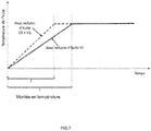
- the figure 7 illustrates the evolution of the average temperature of the oil during a start-up phase of the engine, also known as the Anglo-Saxon "warm-up".
- the abscissa represents time and the ordinate represents the average temperature of the oil.
- the solid line represents the average temperature of the oil when the entire volume of oil is circulated in the lubrication system.
- the dashed line represents the average temperature of the oil when a partial volume of oil is circulated in the lubrication system. Note that the time required to heat the oil at a given temperature is lower in the case where a quantity of partial oil is circulating.
- the electronic control unit can, according to a first option, maintain the shutter element in its first position P1, or, according to a second option, issue a control command to move the shutter element in its third position P3.
- the shutter member 100 moves in X-axis translational movement
- the oil in the first reservoir flows through the openings 106 of the third plate 105.
- the presence of oil in the first tank does not prevent the manipulation of the shutter element 100.
- the oil contained in in the second tank 20 is not heated or is slightly warmed by the oil contained in the first and third tanks 10, 30.
- the oil contained in the second tank 20 is therefore at a lower temperature than the oil circulating in the lubrication system.
- the electronic control unit 7 can detect a situation in which the oil circulates in the engine.
- the lubrication system may exceed a critical value leading to engine damage.
- the electronic control unit can issue a control command to move the shutter element 100 to the second position P2 or the third position P3.
- the oil trapped in the second tank 20 can come out through the second outlet 21, be mixed with the circulating oil in the lubrication system and contribute to lowering the average temperature of the circulating oil.
- the shutter member is moved to its third position P3 which has the effect of putting all of the available oil circulating in the lubrication system.
- Such an option can be controlled by the electronic control unit in several situations.
- a first situation may be the detection of a small amount of oil in the lubrication system.
- a second situation may be the detection that the vehicle is sloping along a longitudinal or transverse axis of the vehicle.
- a third situation may be the detection of an oil temperature threshold.
- a fourth situation can be the detection of a degraded mode operation or the detection of a malfunction of the powertrain.
- the operation described above could very well be reversed. That is to say that during a starting phase of the engine, the shutter element 100 could be in the second position P2.
- the first entry 12 and the first output 11 would be closed and the second input 22 and the second output 21 would be open.
- the first position P1 and the second position P2 are alternated at each new start of the engine.
- the electronic control unit may issue a control command to the actuator 110 to move the shutter member to its third position P3.
- the first and the second input 12, 22 and the first and the second output 11, 21 are open. All of the oil contained in the lubrication system can flow through the drain opening in the third tank 30.
- the shutter member 100 could also be manually manipulated to the third position P3 .
- the reservoir device could comprise at least one additional reservoir juxtaposed with the first or the second reservoir.
- the additional reservoir would include an upper wall with a third inlet and a bottom wall with a third outlet.
- the third exit would lead to the third tank.
- the upper wall of the additional tank would be at the same level as the upper walls of the first and second tanks.
- the bottom wall of the additional tank would be at the same level as the lower walls of the first and second tanks.
- An additional partition wall would separate the additional tank from the first tank or the second tank.
- the inlet and outlet of this additional tank could be opened or closed.
- we can design a tank device comprising N tanks each having an inlet and an outlet. By adapting the number and the arrangement of the lights of the shutter element, it would then be possible to activate each of the N tanks individually or in combination with each other.
- the invention there is a reservoir device for obtaining a rapid warming of the lubricating oil during engine start.
- the device is both simple to manufacture, to use and robust.
- the emptying process is also simple to implement and allows to drain all the oil contained in the lubrication system.
- the wear of the oil is uniform and homogeneous because the device does not include any volume in which oil could stagnate in the absence of emptying.
- the device acts as a safety valve because it provides cold oil to the engine in certain critical situations to prevent overheating of the engine.
Landscapes
- Engineering & Computer Science (AREA)
- Mechanical Engineering (AREA)
- General Engineering & Computer Science (AREA)
- General Details Of Gearings (AREA)
- Lubrication Details And Ventilation Of Internal Combustion Engines (AREA)
Abstract
Dispositif de réservoir (1) d'huile (2) pour moteur (8), caractérisé en ce qu'il comprend : - un premier réservoir (10), un deuxième réservoir (20) et un troisième réservoir (30), le premier réservoir (10) étant muni d'une première sortie (11) vers le troisième réservoir (30) et le deuxième réservoir (20) étant muni d'une deuxième sortie (21) vers le troisième réservoir (30) - et un élément d'obturation (100) apte à obturer la première sortie (11) et apte à obturer la deuxième sortie (21).Oil tank device (1) (2) for an engine (8), characterized in that it comprises: a first reservoir (10), a second reservoir (20) and a third reservoir (30), the first reservoir (10) being provided with a first outlet (11) towards the third reservoir (30) and the second reservoir (30); 20) being provided with a second outlet (21) to the third reservoir (30) - And a shutter member (100) adapted to close the first outlet (11) and able to close the second outlet (21).
Description
La présente invention concerne un dispositif de réservoir d'huile pour moteur. L'invention concerne également un système de lubrification comprenant un tel dispositif de réservoir. L'invention concerne également un groupe motopropulseur comprenant un tel dispositif de réservoir ou un tel système de lubrification. Enfin l'invention concerne un véhicule comprenant un tel dispositif de réservoir, un tel système de lubrification ou un tel groupe motopropulseur.The present invention relates to an engine oil reservoir device. The invention also relates to a lubrication system comprising such a reservoir device. The invention also relates to a powertrain comprising such a reservoir device or such a lubrication system. Finally, the invention relates to a vehicle comprising such a tank device, such a lubrication system or such a powertrain.
Les constructeurs automobiles cherchent sans cesse à optimiser la consommation en énergie des véhicules. Dans le cas de véhicules comprenant un moteur avec un système de lubrification, la viscosité de l'huile, et donc la température de l'huile, joue un rôle important dans le rendement du moteur. Pour optimiser la consommation en énergie de tels véhicules, il convient donc de chauffer rapidement l'huile lors d'un démarrage du moteur. Une première solution consiste à réduire la quantité d'huile en circulation dans le système de lubrification. Toutefois, cette solution présente l'inconvénient de réduire l'intervalle de vidange à cause d'un vieillissement accéléré de l'huile ce qui n'est pas souhaitable pour des questions de coût d'entretien. Une deuxième solution consiste en l'utilisation d'un système de lubrification comprenant des réservoirs multiples permettant de réduire la quantité d'huile en circulation dans le moteur lors du démarrage.Automakers are constantly looking to optimize the energy consumption of vehicles. In the case of vehicles comprising an engine with a lubrication system, the viscosity of the oil, and therefore the temperature of the oil, plays an important role in the efficiency of the engine. To optimize the energy consumption of such vehicles, it is therefore necessary to heat the oil quickly when starting the engine. A first solution is to reduce the amount of oil circulating in the lubrication system. However, this solution has the disadvantage of reducing the emptying interval due to accelerated aging of the oil which is not desirable for maintenance cost issues. A second solution is the use of a lubrication system comprising multiple tanks to reduce the amount of oil circulating in the engine during startup.
Ces systèmes comprennent outre plusieurs réservoirs, des vannes de communication et/ou plusieurs pompes à huiles. Leur complexité provoque un problème de fiabilité or une quantité d'huile insuffisante pour lubrifier le moteur, notamment à pleine charge peut endommager irréversiblement le moteur.These systems include in addition to several tanks, communication valves and / or several oil pumps. Their complexity causes a problem of reliability or a quantity of oil insufficient for Lubricating the engine, especially at full load, can irreversibly damage the engine.
De plus, de l'huile peut rester emprisonnée pendant une durée aléatoire dans l'un de ces réservoirs. Un tel phénomène entraine une usure non uniforme de l'huile et donc une obligation de remplacer l'huile à des intervalles rapprochés.In addition, oil may remain trapped for a random period in one of these tanks. Such a phenomenon causes non-uniform wear of the oil and therefore an obligation to replace the oil at close intervals.
Enfin, de tels systèmes sont complexes à vidanger. De l'huile peut rester emprisonnée dans le système de lubrification à moins de procéder à une dépose complète du carter d'huile ce qui est une opération longue et coûteuse.Finally, such systems are complex to drain. Oil can remain trapped in the lubrication system unless it is completely removed from the sump, which is a time-consuming and expensive operation.
Le but de l'invention est de fournir un dispositif de réservoir remédiant aux inconvénients ci-dessus et améliorant les dispositifs de réservoir connus de l'art antérieur. En particulier, l'invention permet de réaliser un dispositif de réservoir qui soit simple à utiliser, fiable et offrant la possibilité d'accélérer le réchauffement de l'huile lors du démarrage du moteur.The object of the invention is to provide a reservoir device overcomes the above disadvantages and improving tank devices known from the prior art. In particular, the invention allows for a reservoir device that is simple to use, reliable and offers the possibility of accelerating the heating of the oil when starting the engine.
L'invention se rapporte à un dispositif de réservoir d'huile pour moteur comprenant :
- un premier réservoir, un deuxième réservoir et un troisième réservoir, le premier réservoir étant muni d'une première sortie vers le troisième réservoir et le deuxième réservoir étant muni d'une deuxième sortie vers le troisième réservoir
- et un élément d'obturation apte à obturer la première sortie et apte à obturer la deuxième sortie.
- a first reservoir, a second reservoir and a third reservoir, the first reservoir having a first outlet to the third reservoir and the second reservoir having a second outlet to the third reservoir
- and a shutter member adapted to close the first outlet and able to close the second outlet.
Le premier réservoir peut comprendre une première entrée, le deuxième réservoir peut comprendre une deuxième entrée et l'élément d'obturation peut être apte à obturer la première entrée et apte à obturer la deuxième entrée.The first reservoir may include a first inlet, the second reservoir may include a second inlet and the closure element may be able to close the first input and able to close the second input.
La première entrée peut être disposée en un point haut du premier réservoir. La première sortie peut être disposée en un point bas du premier réservoir. La deuxième entrée peut être disposée en un point haut du deuxième réservoir. La deuxième sortie peut être disposée en un point bas du deuxième réservoir. Le troisième réservoir peut être situé en contrebas du premier réservoir et du deuxième réservoir.The first input may be disposed at a high point of the first reservoir. The first outlet may be disposed at a low point of the first tank. The second inlet may be disposed at a high point of the second tank. The second outlet may be disposed at a low point of the second tank. The third tank may be located below the first tank and the second tank.
L'élément d'obturation peut être déplaçable entre au moins trois positions telles que :
- dans une première position de l'élément d'obturation, la première sortie est ouverte et la deuxième sortie est fermée ;
- dans une deuxième position de l'élément d'obturation, la première sortie est fermée et la deuxième sortie est ouverte ;
- dans une troisième position de l'élément d'obturation, la première sortie est ouverte et la deuxième sortie est ouverte.
- in a first position of the shutter member, the first output is open and the second output is closed;
- in a second position of the shutter member, the first output is closed and the second output is open;
- in a third position of the shutter member, the first output is open and the second output is open.
Le dispositif de réservoir peut comprendre un actionneur, notamment un vérin, apte à déplacer l'élément d'obturation entre sa première, sa deuxième ou sa troisième position.The reservoir device may comprise an actuator, in particular a jack, able to move the shutter element between its first, second or third position.
L'élément d'obturation peut comprendre une première lumière et une deuxième lumière, la première lumière coïncidant avec la première sortie lorsque l'élément d'obturation est en première position, la deuxième lumière coïncidant avec la première sortie lorsque l'élément d'obturation est en troisième position. L'élément d'obturation peut comprendre une troisième lumière et une quatrième lumière, la troisième lumière coïncidant avec une entrée du premier réservoir lorsque l'élément d'obturation est en première position, la quatrième lumière coïncidant avec l'entrée du premier réservoir lorsque l'élément d'obturation est en troisième position.The shutter member may include a first lumen and a second lumen, the first lumen coinciding with the first lumen when the shutter member is in the first position, the second lumen coinciding with the first lumen when the aperture member shutter is in third position. The shutter member may comprise a third lumen and a fourth lumen, the third lumen coinciding with an inlet of the first reservoir when the shutter member is in position. first position, the fourth lumen coinciding with the inlet of the first reservoir when the shutter element is in third position.
L'élément d'obturation peut comprendre une face orientée perpendiculairement à un axe de déplacement de l'élément d'obturation, ladite face comprenant au moins une ouverture au travers de laquelle l'huile peut s'écouler lors d'un déplacement de l'élément d'obturation.The closure member may comprise a face oriented perpendicularly to an axis of movement of the closure member, said face comprising at least one opening through which the oil can flow during a displacement of the shutter member. shutter element.
Le dispositif de réservoir peut comprendre une cloison de séparation séparant le premier réservoir du deuxième réservoir, la cloison de séparation étant munie d'au moins une ouverture, l'élément d'obturation étant apte à coulisser au travers d'au moins une ouverture.The reservoir device may comprise a partition wall separating the first reservoir from the second reservoir, the partition wall being provided with at least one opening, the closure element being able to slide through at least one opening.
Le premier réservoir et/ou le deuxième réservoir et/ou le troisième réservoir peut être fabriqué avec un matériau de faible conductivité thermique, notamment du plastique ou des fibres composites.The first reservoir and / or the second reservoir and / or the third reservoir may be made of a material of low thermal conductivity, especially plastic or composite fibers.
Le premier et le deuxième réservoir peuvent comprendre chacun une cloison supérieure horizontale dans laquelle est agencée une entrée, la cloison supérieure du premier réservoir étant positionnée à la même hauteur que la cloison supérieure du deuxième réservoir.The first and second tanks may each comprise a horizontal upper partition in which is arranged an inlet, the upper partition of the first tank being positioned at the same height as the upper wall of the second tank.
L'invention se rapporte également à un système de lubrification comprenant un dispositif de réservoir tel que défini précédemment, une crépine immergée dans le troisième réservoir, une pompe à huile, une connexion hydraulique entre la crépine et la pompe à huile, un carter d'huile entourant le premier, le deuxième et le troisième réservoir et un bouchon de vidange apte à boucher une ouverture de vidange dans le troisième réservoir.The invention also relates to a lubrication system comprising a reservoir device as defined above, a strainer immersed in the third reservoir, an oil pump, a hydraulic connection between the strainer and the oil pump, a crankcase. oil surrounding the first, the second and the third tank and a drain plug adapted to plug a drain opening in the third tank.
L'invention se rapporte également à un groupe motopropulseur comprenant un dispositif de réservoir tel que défini précédemment ou un système de lubrification tel que défini précédemment et une unité de commande électronique apte à commander l'élément d'obturation.The invention also relates to a powertrain comprising a reservoir device as defined above or a lubrication system as defined above and an electronic control unit adapted to control the shutter element.
Enfin, l'invention se rapporte également à un véhicule comprenant un dispositif de réservoir tel que défini précédemment, un système de lubrification tel que défini précédemment ou un groupe motopropulseur tel que défini précédemment.Finally, the invention also relates to a vehicle comprising a reservoir device as defined above, a lubrication system as defined above or a powertrain as defined above.
Ces objets, caractéristiques et avantages de la présente invention seront exposés en détail dans la description suivante d'un mode de réalisation particulier fait à titre non-limitatif en relation avec les figures jointes parmi lesquelles :
- La
figure 1 est une vue schématique d'un véhicule selon un mode de réalisation de l'invention. - La
figure 2 est une vue schématique d'un dispositif de réservoir selon un mode de réalisation de l'invention, un élément d'obturation du dispositif étant dans une première position. - La
figure 3 est une vue schématique du mode de réalisation du dispositif de réservoir, l'élément d'obturation du dispositif étant dans une deuxième position. - La
figure 4 est une vue schématique du mode de réalisation du dispositif de réservoir, l'élément d'obturation du dispositif étant dans une troisième position. - La
figure 5 est une vue schématique d'un élément d'obturation selon un mode de réalisation de l'invention. - La
figure 6 est une vue schématique d'une cloison de séparation du dispositif de réservoir selon un mode de réalisation de l'invention. - La
figure 7 est un graphique comparatif de montée en température de l'huile.
- The
figure 1 is a schematic view of a vehicle according to one embodiment of the invention. - The
figure 2 is a schematic view of a reservoir device according to one embodiment of the invention, a shutter member of the device being in a first position. - The
figure 3 is a schematic view of the embodiment of the reservoir device, the shutter member of the device being in a second position. - The
figure 4 is a schematic view of the embodiment of the reservoir device, the shutter member of the device being in a third position. - The
figure 5 is a schematic view of a closure member according to one embodiment of the invention. - The
figure 6 is a schematic view of a partition of the tank device according to one embodiment of the invention. - The
figure 7 is a comparative graph of temperature rise of the oil.
Sur l'ensemble des figures, la gauche et la droite sont définies arbitrairement. Les termes « haut » et « bas » ou « supérieur » et « inférieur » se rapportent à une orientation verticale en supposant que le véhicule repose sur un sol horizontal. Pour ne pas alourdir les figures, les références numériques ne sont pas reproduites sur toutes les figures illustrant un dispositif de réservoir.On all the figures, the left and the right are arbitrarily defined. The terms "up" and "down" or "upper" and "lower" refer to a vertical orientation assuming that the vehicle rests on a horizontal ground. In order not to weigh down the figures, the numerical references are not reproduced in all the figures illustrating a reservoir device.
La
Les
De plus, le premier réservoir 10 comprend une première entrée 12, le deuxième réservoir 20 comprend une deuxième entrée 22. L'élément d'obturation 100 est apte à obturer la première entrée 12 et apte à obturer la deuxième entrée 22. La première entrée 12 est disposée en un point haut du premier réservoir 10.In addition, the
La première sortie 11 est disposée en un point bas du premier réservoir 10. Avantageusement, la première entrée 12 est située à l'aplomb de la première sortie 11. La deuxième entrée 22 est disposée en un point haut du deuxième réservoir 20. La deuxième sortie 21 est disposée en un point bas du deuxième réservoir 20. Avantageusement, la deuxième entrée 22 est située à l'aplomb de la deuxième sortie 21. Le troisième réservoir 30 est situé en contrebas du premier réservoir 10 et du deuxième réservoir 20. Le premier réservoir 10 et le deuxième réservoir 20 comprennent chacun une paroi inférieure 14, 24 munie respectivement de la première sortie 11 et de la deuxième sortie 21. L'ensemble de ces deux parois inférieures 14, 24 constituent également une paroi supérieure du troisième réservoir 30. Les deux parois inférieures 14, 24 s'étendent selon un plan horizontal et à un même niveau, c'est-à-dire à une même hauteur par rapport à un axe vertical. Les deux parois inférieures s'étendent sur toute la largeur du carter d'huile 54.The
De même, le premier réservoir 10 et le deuxième réservoir 20 comprennent chacun une paroi supérieure 13, 23 munie respectivement de la première entrée 12 et de la deuxième entrée 22. Les deux parois supérieures 13, 23 s'étendent selon un plan horizontal et à un même niveau, c'est-à-dire à une même hauteur par rapport à un axe vertical. Les parois supérieures 13, 23 du premier et du deuxième réservoir 10, 20 sont donc parallèles aux parois inférieures 14, 24 du premier et du deuxième réservoir. Les deux parois supérieures s'étendent également sur toute la largeur du carter d'huile 54. Dans le cas ou le carter d'huile a une section globalement trapézoïdale avec une grande base vers le haut, les parois supérieures 13, 23 ont une taille plus importantes que les parois inférieures 14, 24. En variante le carter d'huile pourrait avoir une toute autre forme et le premier et deuxième réservoir pourraient n'occuper qu'une partie de la largeur du carter d'huile 54.Similarly, the
Latéralement le premier et le deuxième réservoir 10, 20 sont délimités par le carter d'huile 54 d'une part et par une cloison de séparation 41 d'autre part. La cloison de séparation 41 est commune au premier et au deuxième réservoir 10, 20. La cloison de séparation 41 est de forme plane, est verticale et a une première face tournée vers le premier réservoir 10 et une deuxième face, opposée à la première face, tournée vers le deuxième réservoir 20. Le premier et le deuxième réservoir 10, 20 sont donc voisins et adjacents. Ils peuvent avoir un volume sensiblement identique comme représentés sur les
L'élément d'obturation 100 est déplaçable entre au moins trois positions P1, P2, P3 telles que :
- dans une première position P1 de l'élément d'obturation 100,
la première sortie 11 et la première entrée 12 sont ouvertes et la deuxième sortie 21 et la deuxième entrée 22 sont fermées ; - dans une deuxième position P2 de l'élément d'obturation 100,
la première sortie 11 et la première entrée 12 sont fermées et la deuxième sortie 21 et la deuxième entrée 22 sont ouvertes ; - dans une troisième position P3 de l'élément d'obturation 100,
la première sortie 11, la premièreentrée 12, la deuxième sortie 21 et la deuxième entrée 22 sont ouvertes.
- in a first position P1 of the
shutter element 100, thefirst output 11 and thefirst input 12 are open and thesecond output 21 and thesecond input 22 are closed; - in a second position P2 of the
shutter element 100, thefirst output 11 and thefirst input 12 are closed and thesecond output 21 and thesecond input 22 are open; - in a third position P3 of the
shutter element 100, thefirst output 11, thefirst input 12, thesecond output 21 and thesecond input 22 are open.
La première position P1 est illustrée sur la
Pour ce faire, l'élément d'obturation 100, particulièrement visible sur la
La première plaque 107 comprend une première lumière 101 et une deuxième lumière 102. La deuxième plaque 108 comprend une troisième lumière 103 et une quatrième lumière 104. Les quatre lumières 101, 102, 103, 104 sont des fentes rectangulaires alignées parallèlement à la troisième plaque 105. En dehors de ces 4 lumières, la première et la deuxième plaque 107, 108 sont pleines. La première et la deuxième lumière 101, 102 sont disjointes et espacées par une partie pleine. De même, la troisième et la quatrième lumière 103, 104 sont disjointes et espacées par une partie pleine. La troisième lumière 103 est à l'aplomb au dessus de la première lumière 101. La quatrième lumière 104 est à l'aplomb au dessus de la deuxième lumière 102.The
Lorsque l'élément d'obturation 100 est en première position P1 :
- la première lumière 101 coïncide avec la première
sortie 11, - la troisième lumière 103 coïncide avec la première
entrée 12, - une partie pleine de la première
plaque 107 coïncide avec la deuxièmesortie 21, - et une partie pleine de la deuxième
plaque 108 coïncide avec la deuxième entrée 22.
- the
first light 101 coincides with thefirst output 11, - the
third light 103 coincides with thefirst input 12, - a solid part of the
first plate 107 coincides with thesecond outlet 21, - and a solid portion of the
second plate 108 coincides with thesecond inlet 22.
Lorsque l'élément d'obturation 100 est en deuxième position P2 :
- une partie pleine de la première
plaque 107 coïncide avec la premièresortie 11, - une partie pleine de la deuxième
plaque 108 coïncide avec la premièreentrée 12, la première plaque 107 est décalée par rapport à la deuxièmesortie 21,- et la deuxième
plaque 108 est décalée par rapport à la deuxième entrée 22.
- a solid part of the
first plate 107 coincides with thefirst outlet 11, - a solid part of the
second plate 108 coincides with thefirst input 12, - the
first plate 107 is offset relative to thesecond outlet 21, - and the
second plate 108 is offset from thesecond input 22.
Lorsque l'élément d'obturation 100 est en troisième position P3 :
- la deuxième lumière 102 coïncide avec la première
sortie 11, - la quatrième lumière 104 coïncide avec la première
entrée 12, la première plaque 107 est décalée par rapport à la deuxièmesortie 21,- et la deuxième
plaque 108 est décalée par rapport à la deuxième entrée 22.
- the
second light 102 coincides with thefirst output 11, - the
fourth light 104 coincides with thefirst input 12, - the
first plate 107 is offset relative to thesecond outlet 21, - and the
second plate 108 is offset from thesecond input 22.
Lorsqu'une partie pleine de la première plaque 107 est en vis-à-vis de la première sortie 11, elle obture la première sortie 11 de sorte que l'huile contenue dans le premier réservoir ne peut pas s'échapper par cette sortie. Il en va de même pour la deuxième sortie 21. De manière analogue, lorsqu'une partie pleine de la deuxième plaque 108 est en vis-à-vis de la première entrée 12, elle obture la première entrée 12 de sorte que l'huile arrivant en amont du dispositif de réservoir ne peut pas rentrer dans le premier réservoir 10. Il en va de même pour la deuxième entrée 22. Une fuite au niveau de l'interface formée par une partie pleine de la première ou de la deuxième plaque 107, 108 d'une part et une entrée 12, 22 ou une sortie 11, 21 d'autre part pourrait être acceptable si elle demeure négligeable par rapport au débit d'huile général dans le système de lubrification.When a solid portion of the
En variante, les lumières 101, 102, 103, 104 pourraient être agencées différemment. Par exemple, la deuxième lumière 102 pourrait être positionnée vers une extrémité de la première plaque 107 du coté du deuxième réservoir 20 et coopérer avec la deuxième sortie 21. Et de même, la quatrième lumière 104 pourrait être positionnée vers une extrémité de la deuxième plaque 108 du coté du deuxième réservoir 20 et coopérer avec la deuxième entrée 22.Alternatively, the
Le déplacement de l'élément d'obturation 100 d'une position à l'autre est un déplacement en translation selon un axe X. L'axe X est horizontal et perpendiculaire à l'orientation des fentes rectangulaires constituant les quatre lumières 101, 102, 103, 104. L'axe X peut également être défini comme l'axe perpendiculaire à la troisième plaque 105 ou comme l'axe perpendiculaire à la cloison de séparation 41. Afin d'animer en translation l'élément d'obturation 100, le dispositif de réservoir 1 comprend un actionneur 110, notamment un vérin, apte à déplacer l'élément d'obturation 100 entre sa première sa deuxième ou sa troisième position P1, P2, P3. L'actionneur 110 est raccordé électriquement à l'unité de commande électronique 7. Le vérin comprend un bras 111 fixé à la troisième plaque 105. Le bras 111 traverse le carter d'huile 54 et la paroi latérale du premier réservoir 10. Un dispositif d'étanchéité peut être intégré à l'interface entre le bras 111 et le carter d'huile ou à l'interface entre le bras 111 et le premier réservoir pour empêcher une fuite d'huile 2 vers l'extérieur.The displacement of the
En variante, le dispositif de réservoir pourrait être facilement adapté pour coopérer avec un élément d'obturation animé d'un mouvement en rotation, par exemple un mouvement de rotation autour de l'axe vertical. L'actionneur pourrait alors comprendre un moteur apte à faire tourner l'élément d'obturation autour de l'axe vertical. En fonction de la position angulaire de l'élément d'obturation par rapport aux parois inférieures et supérieures du premier et du deuxième réservoir, les entrées et les sorties respectives de ces réservoirs pourraient être ouvertes ou fermées.Alternatively, the reservoir device could be easily adapted to cooperate with a shutter member animated with a rotational movement, for example a rotational movement about the vertical axis. The actuator could then include a motor adapted to rotate the shutter element about the vertical axis. Depending on the angular position of the shutter member relative to the lower and upper walls of the first and second tanks, the respective inlets and outlets of these tanks could be opened or closed.
La troisième plaque 105 comprend au moins une ouverture 106 au travers de laquelle l'huile 2 peut s'écouler lors d'un déplacement de l'élément d'obturation 100. Selon le mode de réalisation représenté à la
La cloison de séparation 41 est munie d'au moins une ouverture 42a, 42b au travers desquelles l'élément d'obturation 100 est apte à coulisser. Selon le mode de réalisation représenté à la
La cloison de séparation 41, mais également les parois supérieures 13, 23 et inférieures 14, 24 du premier et du deuxième réservoir 10, 20 peuvent être réalisés à partir d'un matériau de faible conductivité thermique, notamment du plastique ou des fibres composites. Les parois latérales du premier et du deuxième réservoir 10, 20 au niveau du carter d'huile 54 peuvent être confondues avec le carter d'huile lui-même au bien former une double paroi le long du carter d'huile. Dans cette deuxième hypothèse la double paroi peut être réalisée à partir du même matériau que celui utilisé pour la cloison de séparation 41, les parois supérieures 13, 23 et les parois inférieures 14, 24.The
Le dispositif de réservoir comprend un ensemble de cloisons ou de parois et un élément d'obturation formé de trois plaques. La conception du dispositif de réservoir met donc en oeuvre des formes simples. Le dispositif de réservoir est donc facile à produire et fiable. Le dispositif de réservoir peut être adapté à tout carter d'huile existant sous réserve d'avoir suffisamment de place pour loger un actionneur.The reservoir device comprises a set of partitions or walls and a shutter member formed of three plates. The design of the reservoir device thus implements simple shapes. The tank device is therefore easy to produce and reliable. The tank device can be adapted to any existing oil sump subject to having sufficient room to house an actuator.
Nous allons à présent détailler le fonctionnement du dispositif de réservoir. En fonction d'une situation ou d'une configuration du véhicule 5, l'unité de commande électronique 7 émet un ordre de commande à destination de l'actionneur 110. A réception de cet ordre de commande, l'actionneur déplace l'élément d'obturation dans une position P1, P2 ou P3 souhaitée. En variante, l'actionneur peut positionner l'élément d'obturation dans une position intermédiaire entre P1 et P2 ou entre P2 et P3. Ainsi une entrée 11, 21 ou une sortie 12, 22 du premier ou du deuxième réservoir 10, 20 pourrait être partiellement ouverte ou partiellement fermée. Il n'existe aucune position de l'élément d'obturation 100 dans laquelle la première sortie 11 et la deuxième sortie 21 sont simultanément complètement fermées. De même, il n'existe aucune position de l'élément d'obturation 100 dans laquelle la première entrée 12 et la deuxième entrée 22 sont simultanément fermées. De l'huile peut donc toujours circuler dans le système de lubrification. Un blocage du système de lubrification par l'élément d'obturation 100 est donc mécaniquement impossible.We will now detail the operation of the tank device. Depending on a situation or a configuration of the
Lorsque l'élément d'obturation 100 est en première position P1, l'huile 2 contenue dans le premier réservoir 10 peut s'écouler dans le troisième réservoir 30 au travers de la première sortie 11. L'huile 2 est aspirée du troisième réservoir 30 par la pompe à huile 52 au travers de la crépine 51 et de la conduite hydraulique 53. L'huile est ensuite dirigée vers les organes à lubrifier du moteur puis retombe par gravité au dessus du premier et du deuxième réservoir 10, 20. L'huile se répand sur les parois supérieures 13, 23 à l'extérieur du premier et du deuxième réservoir 10, 20. L'huile peut retourner dans le premier réservoir en passant par l'entrée 12 ouverte. En remarque, l'espace situé au dessus des parois supérieures 13, 23 pourrait être aménagé pour faciliter l'écoulement de l'huile vers la première et la deuxième entrée 12, 22, notamment lorsque le véhicule est incliné latéralement ou longitudinalement. L'huile contenue dans le deuxième réservoir 20 est emprisonnée. L'huile ne peut pas ressortir du deuxième réservoir 20 car la deuxième sortie 21 est fermée. L'huile ne peut pas non plus rentrer dans le deuxième réservoir 20 car la deuxième entrée 22 est fermée. Le volume d'huile dans le deuxième réservoir 20 est donc stable. Ainsi, Le volume d'huile en circulation dans le système de lubrification correspond au volume total d'huile auquel est soustrait le volume d'huile emprisonné dans le deuxième réservoir. Le moteur fonctionne donc avec une quantité d'huile restreinte, autrement dit un volume d'huile partiel, ce qui accélère son réchauffement lors d'une phase de démarrage du moteur avec de l'huile froide.When the
La
Après la phase de démarrage du moteur, c'est-à-dire par exemple une fois que la température de l'huile est stabilisée à une température de fonctionnement, l'unité de commande électronique peut, selon une première option, maintenir l'élément d'obturation dans sa première position P1, ou bien, selon une deuxième option, émettre un ordre de commande pour déplacer l'élément d'obturation dans sa troisième position P3. Lorsque l'élément d'obturation 100 se déplace suivant un mouvement de translation d'axe X, l'huile présente dans le premier réservoir s'écoule au travers des ouvertures 106 de la troisième plaque 105. Ainsi la présence d'huile dans le premier réservoir n'empêche pas la manipulation l'élément d'obturation 100.After the engine start phase, that is to say for example once the temperature of the oil is stabilized at an operating temperature, the electronic control unit can, according to a first option, maintain the shutter element in its first position P1, or, according to a second option, issue a control command to move the shutter element in its third position P3. When the
Selon la première option, on conserve une partie de l'huile emprisonnée dans le deuxième réservoir 20. Grâce à l'utilisation d'un matériau de faible conductivité thermique pour la fabrication des cloisons ou des parois du deuxième réservoir 20, l'huile contenue dans le deuxième réservoir 20 n'est pas réchauffée ou est faiblement réchauffée par l'huile contenue dans le premier et le troisième réservoir 10, 30. L'huile contenue dans le deuxième réservoir 20 est par conséquent à une température plus faible que l'huile en circulation dans le système de lubrification. En fonction de critères basés sur la température de l'huile, la température ambiante, la vitesse du véhicule, la charge ou le régime du moteur, l'unité de commande électronique 7 peut détecter une situation dans laquelle l'huile en circulation dans le système de lubrification risquerait de dépasser une valeur critique conduisant à un endommagement du moteur. Dans une telle situation, l'unité de commande électronique peut émettre un ordre de commande pour déplacer l'élément d'obturation 100 vers la deuxième position P2 ou la troisième position P3. Ainsi, l'huile emprisonnée dans le deuxième réservoir 20 peut ressortir par la deuxième sortie 21, être mélangée à l'huile en circulation dans le système de lubrification et contribuer à faire baisser la température moyenne de l'huile en circulation.According to the first option, some of the oil trapped in the
Selon la deuxième option, l'élément d'obturation est déplacé dans sa troisième position P3 ce qui a pour effet de mettre la totalité de l'huile disponible en circulation dans le système de lubrification. Une telle option peut être commandée par l'unité de commande électronique dans plusieurs situations. Une première situation peut être la détection d'une quantité d'huile faible dans le système de lubrification. Une deuxième situation peut être la détection que le véhicule est en pente selon un axe longitudinal ou transversal du véhicule. Une troisième situation peut être la détection d'un seuil de température d'huile. Une quatrième situation peut être la détection d'un fonctionnement en mode dégradé ou la détection d'un dysfonctionnement du groupe motopropulseur.According to the second option, the shutter member is moved to its third position P3 which has the effect of putting all of the available oil circulating in the lubrication system. Such an option can be controlled by the electronic control unit in several situations. A first situation may be the detection of a small amount of oil in the lubrication system. A second situation may be the detection that the vehicle is sloping along a longitudinal or transverse axis of the vehicle. A third situation may be the detection of an oil temperature threshold. A fourth situation can be the detection of a degraded mode operation or the detection of a malfunction of the powertrain.
Le deuxième réservoir 20 étant analogue au premier réservoir 10 le fonctionnement décrit ci-dessus pourrait très bien être inversé. C'est-à-dire que lors d'une phase de démarrage du moteur, l'élément d'obturation 100 pourrait être en deuxième position P2. La première entrée 12 et la première sortie 11 seraient fermées et la deuxième entrée 22 et la deuxième sortie 21 seraient ouvertes. Avantageusement, la première position P1 et la deuxième position P2 sont alternées à chaque nouveau démarrage du moteur. Ainsi, on s'assure que la totalité de l'huile est régulièrement mise en circulation dans le système d'huile et que l'usure de l'huile est uniforme ou homogène. L'emprisonnement ou la stagnation de l'huile est donc parfaitement contrôlée.Since the
Dans le cas d'une procédure de vidange, l'unité de commande électronique peut émettre un ordre de commande à l'actionneur 110 pour déplacer l'élément d'obturation selon sa troisième position P3. La première et la deuxième entrée 12, 22 et la première et la deuxième sortie 11, 21 sont ouvertes. La totalité de l'huile contenue dans le système de lubrification peut s'écouler au travers de l'ouverture de vidange dans le troisième réservoir 30. En variante, l'élément d'obturation 100 pourrait être également manipulé manuellement vers la troisième position P3.In the case of a draining procedure, the electronic control unit may issue a control command to the
Selon une autre variante de réalisation, le dispositif de réservoir pourrait comprendre au moins un réservoir additionnel juxtaposé au premier ou au deuxième réservoir. Le réservoir additionnel comprendrait une paroi supérieure munie d'une troisième entrée et une paroi inférieure munie d'une troisième sortie. La troisième sortie déboucherait vers le troisième réservoir. La paroi supérieure du réservoir supplémentaire serait au même niveau que les parois supérieures du premier et du deuxième réservoir. La paroi inférieure du réservoir supplémentaire serait au même niveau que les parois inférieures du premier et du deuxième réservoir. Une cloison de séparation supplémentaire séparerait le réservoir supplémentaire du premier réservoir ou du deuxième réservoir. En fonction de la position d'un élément d'obturation l'entrée et la sortie de ce réservoir additionnel pourraient être ouvertes ou fermées. De la même manière, on peut concevoir un dispositif de réservoir comportant N réservoirs disposant chacun d'une entrée et d'une sortie. En adaptant le nombre et la disposition des lumières de l'élément d'obturation, il serait alors possible d'activer chacun des N réservoirs individuellement ou en combinaison les uns avec les autres.According to another variant embodiment, the reservoir device could comprise at least one additional reservoir juxtaposed with the first or the second reservoir. The additional reservoir would include an upper wall with a third inlet and a bottom wall with a third outlet. The third exit would lead to the third tank. The upper wall of the additional tank would be at the same level as the upper walls of the first and second tanks. The bottom wall of the additional tank would be at the same level as the lower walls of the first and second tanks. An additional partition wall would separate the additional tank from the first tank or the second tank. Depending on the position of a shutter member the inlet and outlet of this additional tank could be opened or closed. In the same way, we can design a tank device comprising N tanks each having an inlet and an outlet. By adapting the number and the arrangement of the lights of the shutter element, it would then be possible to activate each of the N tanks individually or in combination with each other.
Grâce à l'invention, on dispose d'un dispositif de réservoir permettant d'obtenir un réchauffement rapide de l'huile de lubrification lors du démarrage du moteur. Le dispositif est à la fois simple à fabriquer, à utiliser et robuste. Le procédé de vidange est également simple à mettre en oeuvre et permet de vidanger la totalité de l'huile contenue dans le système de lubrification. L'usure de l'huile est uniforme et homogène car le dispositif ne comprend aucun volume dans lequel de l'huile pourrait stagner en l'absence de vidange. De plus le dispositif agit comme une soupape de sécurité car il permet de fournir de l'huile froide au moteur dans certaines situations critiques afin d'éviter une surchauffe du moteur.Thanks to the invention, there is a reservoir device for obtaining a rapid warming of the lubricating oil during engine start. The device is both simple to manufacture, to use and robust. The emptying process is also simple to implement and allows to drain all the oil contained in the lubrication system. The wear of the oil is uniform and homogeneous because the device does not include any volume in which oil could stagnate in the absence of emptying. In addition, the device acts as a safety valve because it provides cold oil to the engine in certain critical situations to prevent overheating of the engine.
Claims (13)
Applications Claiming Priority (1)
| Application Number | Priority Date | Filing Date | Title |
|---|---|---|---|
| FR1754131A FR3066230B1 (en) | 2017-05-11 | 2017-05-11 | ENGINE OIL TANK DEVICE |
Publications (2)
| Publication Number | Publication Date |
|---|---|
| EP3401521A1 true EP3401521A1 (en) | 2018-11-14 |
| EP3401521B1 EP3401521B1 (en) | 2021-03-31 |
Family
ID=59325472
Family Applications (1)
| Application Number | Title | Priority Date | Filing Date |
|---|---|---|---|
| EP18170867.8A Active EP3401521B1 (en) | 2017-05-11 | 2018-05-04 | Oil reservoir device for engine |
Country Status (2)
| Country | Link |
|---|---|
| EP (1) | EP3401521B1 (en) |
| FR (1) | FR3066230B1 (en) |
Cited By (1)
| Publication number | Priority date | Publication date | Assignee | Title |
|---|---|---|---|---|
| CN114483251A (en) * | 2022-03-11 | 2022-05-13 | 东风汽车集团股份有限公司 | Oil pan assembly, engine oil cooling method and automobile |
Citations (3)
| Publication number | Priority date | Publication date | Assignee | Title |
|---|---|---|---|---|
| JPS5341655A (en) * | 1976-09-27 | 1978-04-15 | Kubota Ltd | Lubricating oil sink for engine |
| JPS5560410U (en) * | 1978-10-21 | 1980-04-24 | ||
| JP2006242052A (en) * | 2005-03-02 | 2006-09-14 | Toyota Motor Corp | Oil pan |
-
2017
- 2017-05-11 FR FR1754131A patent/FR3066230B1/en not_active Expired - Fee Related
-
2018
- 2018-05-04 EP EP18170867.8A patent/EP3401521B1/en active Active
Patent Citations (3)
| Publication number | Priority date | Publication date | Assignee | Title |
|---|---|---|---|---|
| JPS5341655A (en) * | 1976-09-27 | 1978-04-15 | Kubota Ltd | Lubricating oil sink for engine |
| JPS5560410U (en) * | 1978-10-21 | 1980-04-24 | ||
| JP2006242052A (en) * | 2005-03-02 | 2006-09-14 | Toyota Motor Corp | Oil pan |
Cited By (2)
| Publication number | Priority date | Publication date | Assignee | Title |
|---|---|---|---|---|
| CN114483251A (en) * | 2022-03-11 | 2022-05-13 | 东风汽车集团股份有限公司 | Oil pan assembly, engine oil cooling method and automobile |
| CN114483251B (en) * | 2022-03-11 | 2022-12-23 | 东风汽车集团股份有限公司 | Oil pan assembly, engine oil cooling method and automobile |
Also Published As
| Publication number | Publication date |
|---|---|
| EP3401521B1 (en) | 2021-03-31 |
| FR3066230A1 (en) | 2018-11-16 |
| FR3066230B1 (en) | 2021-06-04 |
Similar Documents
| Publication | Publication Date | Title |
|---|---|---|
| EP3145745B1 (en) | Vehicle-mounted hydraulic assistance device and method for evacuating such a device | |
| FR2928412A1 (en) | EXHAUST GAS POST-TREATMENT DEVICE | |
| EP3401521B1 (en) | Oil reservoir device for engine | |
| FR2967211A1 (en) | DEVICE FOR CONTROLLING COOLANT FLOW RATE AND COOLING SYSTEM EQUIPPED WITH SUCH A DEVICE | |
| FR2908453A1 (en) | OIL PAN OF A COMBUSTION ENGINE. | |
| EP3728906B1 (en) | Pump suction circuit | |
| WO2014169962A1 (en) | Vane-type rotary vacuum pump | |
| FR2996177A1 (en) | VEHICLE WITH IMPROVED HYDRAULIC ASSISTANCE INTEGRATING A SYSTEM FOR MANAGING OIL LEVELS IN THE HOUSINGS OF HYDRAULIC DEVICES | |
| EP3265686B1 (en) | Actuator for hydraulic control of a clutch | |
| FR3074252A1 (en) | ENGINE OIL TANK | |
| FR2860548A1 (en) | Power strainer for oil pump of thermal engine, has one opening of blocking chamber connecting suction inlets that are situated in direction opposite to another opening, and inertial blocking unit to block one opening relative to another | |
| FR3072065B1 (en) | SWING OF HYDRAULIC FLUID AT START-UP | |
| FR3072148B1 (en) | METHOD AND SYSTEM FOR SELF-MAINTENANCE | |
| FR3059356A1 (en) | SYSTEM FOR LUBRICATING AN INTERNAL COMBUSTION ENGINE | |
| FR2984401A1 (en) | Motorized device for use in car, has control system controlling supply of lubricant arrangement, where predetermined amount of lubricant is added to housing when level is below threshold to be attained | |
| EP1229218B1 (en) | Automatic device for regulation of oil level in a combustion engine | |
| FR3027997A1 (en) | OIL PAN WITH LINK HOUSING CONTAINING OIL | |
| FR3020458A1 (en) | METHOD AND APPARATUS FOR MEASURING THE DEAD VOLUME OF A CYLINDER HEAD | |
| FR3107329A1 (en) | Multiport valve with rotary plug and hydraulic pressure control | |
| EP2956637B1 (en) | Oil circuit for an internal combustion engine with optimised actuating means | |
| WO2015091773A1 (en) | Control valve with stepped sealing segment | |
| FR3124322A1 (en) | Electronic system comprising at least one electrical and/or electronic component and a thermal regulation device. | |
| FR2991395A1 (en) | Feeding circuit for feeding fuel e.g. petrol, to thermal engine of car, has exhaust port allowing discharge of air expelled from intake manifold via retention vessel of degassing device, without passing through fuel tank | |
| FR3091897A1 (en) | Cooling system | |
| FR3060648A1 (en) | SYSTEM FOR MONITORING AN ENGINE LUBRICATION CIRCUIT COMPRISING A BUFFER RESERVOIR |
Legal Events
| Date | Code | Title | Description |
|---|---|---|---|
| PUAI | Public reference made under article 153(3) epc to a published international application that has entered the european phase |
Free format text: ORIGINAL CODE: 0009012 |
|
| STAA | Information on the status of an ep patent application or granted ep patent |
Free format text: STATUS: THE APPLICATION HAS BEEN PUBLISHED |
|
| AK | Designated contracting states |
Kind code of ref document: A1 Designated state(s): AL AT BE BG CH CY CZ DE DK EE ES FI FR GB GR HR HU IE IS IT LI LT LU LV MC MK MT NL NO PL PT RO RS SE SI SK SM TR |
|
| AX | Request for extension of the european patent |
Extension state: BA ME |
|
| STAA | Information on the status of an ep patent application or granted ep patent |
Free format text: STATUS: REQUEST FOR EXAMINATION WAS MADE |
|
| 17P | Request for examination filed |
Effective date: 20190510 |
|
| RBV | Designated contracting states (corrected) |
Designated state(s): AL AT BE BG CH CY CZ DE DK EE ES FI FR GB GR HR HU IE IS IT LI LT LU LV MC MK MT NL NO PL PT RO RS SE SI SK SM TR |
|
| STAA | Information on the status of an ep patent application or granted ep patent |
Free format text: STATUS: EXAMINATION IS IN PROGRESS |
|
| 17Q | First examination report despatched |
Effective date: 20191202 |
|
| REG | Reference to a national code |
Ref country code: DE Ref legal event code: R079 Ref document number: 602018014587 Country of ref document: DE Free format text: PREVIOUS MAIN CLASS: F01M0005000000 Ipc: F01M0005020000 |
|
| RIC1 | Information provided on ipc code assigned before grant |
Ipc: F01M 5/02 20060101AFI20200918BHEP Ipc: F01M 11/00 20060101ALI20200918BHEP |
|
| GRAP | Despatch of communication of intention to grant a patent |
Free format text: ORIGINAL CODE: EPIDOSNIGR1 |
|
| STAA | Information on the status of an ep patent application or granted ep patent |
Free format text: STATUS: GRANT OF PATENT IS INTENDED |
|
| INTG | Intention to grant announced |
Effective date: 20201030 |
|
| GRAS | Grant fee paid |
Free format text: ORIGINAL CODE: EPIDOSNIGR3 |
|
| GRAA | (expected) grant |
Free format text: ORIGINAL CODE: 0009210 |
|
| STAA | Information on the status of an ep patent application or granted ep patent |
Free format text: STATUS: THE PATENT HAS BEEN GRANTED |
|
| AK | Designated contracting states |
Kind code of ref document: B1 Designated state(s): AL AT BE BG CH CY CZ DE DK EE ES FI FR GB GR HR HU IE IS IT LI LT LU LV MC MK MT NL NO PL PT RO RS SE SI SK SM TR |
|
| REG | Reference to a national code |
Ref country code: GB Ref legal event code: FG4D Free format text: NOT ENGLISH Ref country code: CH Ref legal event code: EP |
|
| REG | Reference to a national code |
Ref country code: DE Ref legal event code: R096 Ref document number: 602018014587 Country of ref document: DE Ref country code: AT Ref legal event code: REF Ref document number: 1377167 Country of ref document: AT Kind code of ref document: T Effective date: 20210415 |
|
| REG | Reference to a national code |
Ref country code: IE Ref legal event code: FG4D Free format text: LANGUAGE OF EP DOCUMENT: FRENCH |
|
| REG | Reference to a national code |
Ref country code: LT Ref legal event code: MG9D |
|
| PG25 | Lapsed in a contracting state [announced via postgrant information from national office to epo] |
Ref country code: NO Free format text: LAPSE BECAUSE OF FAILURE TO SUBMIT A TRANSLATION OF THE DESCRIPTION OR TO PAY THE FEE WITHIN THE PRESCRIBED TIME-LIMIT Effective date: 20210630 Ref country code: FI Free format text: LAPSE BECAUSE OF FAILURE TO SUBMIT A TRANSLATION OF THE DESCRIPTION OR TO PAY THE FEE WITHIN THE PRESCRIBED TIME-LIMIT Effective date: 20210331 Ref country code: HR Free format text: LAPSE BECAUSE OF FAILURE TO SUBMIT A TRANSLATION OF THE DESCRIPTION OR TO PAY THE FEE WITHIN THE PRESCRIBED TIME-LIMIT Effective date: 20210331 Ref country code: BG Free format text: LAPSE BECAUSE OF FAILURE TO SUBMIT A TRANSLATION OF THE DESCRIPTION OR TO PAY THE FEE WITHIN THE PRESCRIBED TIME-LIMIT Effective date: 20210630 |
|
| PG25 | Lapsed in a contracting state [announced via postgrant information from national office to epo] |
Ref country code: RS Free format text: LAPSE BECAUSE OF FAILURE TO SUBMIT A TRANSLATION OF THE DESCRIPTION OR TO PAY THE FEE WITHIN THE PRESCRIBED TIME-LIMIT Effective date: 20210331 Ref country code: LV Free format text: LAPSE BECAUSE OF FAILURE TO SUBMIT A TRANSLATION OF THE DESCRIPTION OR TO PAY THE FEE WITHIN THE PRESCRIBED TIME-LIMIT Effective date: 20210331 Ref country code: SE Free format text: LAPSE BECAUSE OF FAILURE TO SUBMIT A TRANSLATION OF THE DESCRIPTION OR TO PAY THE FEE WITHIN THE PRESCRIBED TIME-LIMIT Effective date: 20210331 |
|
| REG | Reference to a national code |
Ref country code: NL Ref legal event code: MP Effective date: 20210331 |
|
| REG | Reference to a national code |
Ref country code: AT Ref legal event code: MK05 Ref document number: 1377167 Country of ref document: AT Kind code of ref document: T Effective date: 20210331 |
|
| PG25 | Lapsed in a contracting state [announced via postgrant information from national office to epo] |
Ref country code: CZ Free format text: LAPSE BECAUSE OF FAILURE TO SUBMIT A TRANSLATION OF THE DESCRIPTION OR TO PAY THE FEE WITHIN THE PRESCRIBED TIME-LIMIT Effective date: 20210331 Ref country code: EE Free format text: LAPSE BECAUSE OF FAILURE TO SUBMIT A TRANSLATION OF THE DESCRIPTION OR TO PAY THE FEE WITHIN THE PRESCRIBED TIME-LIMIT Effective date: 20210331 Ref country code: LT Free format text: LAPSE BECAUSE OF FAILURE TO SUBMIT A TRANSLATION OF THE DESCRIPTION OR TO PAY THE FEE WITHIN THE PRESCRIBED TIME-LIMIT Effective date: 20210331 Ref country code: AT Free format text: LAPSE BECAUSE OF FAILURE TO SUBMIT A TRANSLATION OF THE DESCRIPTION OR TO PAY THE FEE WITHIN THE PRESCRIBED TIME-LIMIT Effective date: 20210331 Ref country code: NL Free format text: LAPSE BECAUSE OF FAILURE TO SUBMIT A TRANSLATION OF THE DESCRIPTION OR TO PAY THE FEE WITHIN THE PRESCRIBED TIME-LIMIT Effective date: 20210331 Ref country code: SM Free format text: LAPSE BECAUSE OF FAILURE TO SUBMIT A TRANSLATION OF THE DESCRIPTION OR TO PAY THE FEE WITHIN THE PRESCRIBED TIME-LIMIT Effective date: 20210331 |
|
| PG25 | Lapsed in a contracting state [announced via postgrant information from national office to epo] |
Ref country code: SK Free format text: LAPSE BECAUSE OF FAILURE TO SUBMIT A TRANSLATION OF THE DESCRIPTION OR TO PAY THE FEE WITHIN THE PRESCRIBED TIME-LIMIT Effective date: 20210331 Ref country code: RO Free format text: LAPSE BECAUSE OF FAILURE TO SUBMIT A TRANSLATION OF THE DESCRIPTION OR TO PAY THE FEE WITHIN THE PRESCRIBED TIME-LIMIT Effective date: 20210331 Ref country code: PL Free format text: LAPSE BECAUSE OF FAILURE TO SUBMIT A TRANSLATION OF THE DESCRIPTION OR TO PAY THE FEE WITHIN THE PRESCRIBED TIME-LIMIT Effective date: 20210331 Ref country code: PT Free format text: LAPSE BECAUSE OF FAILURE TO SUBMIT A TRANSLATION OF THE DESCRIPTION OR TO PAY THE FEE WITHIN THE PRESCRIBED TIME-LIMIT Effective date: 20210802 Ref country code: IS Free format text: LAPSE BECAUSE OF FAILURE TO SUBMIT A TRANSLATION OF THE DESCRIPTION OR TO PAY THE FEE WITHIN THE PRESCRIBED TIME-LIMIT Effective date: 20210731 |
|
| REG | Reference to a national code |
Ref country code: CH Ref legal event code: PL |
|
| REG | Reference to a national code |
Ref country code: DE Ref legal event code: R097 Ref document number: 602018014587 Country of ref document: DE |
|
| PG25 | Lapsed in a contracting state [announced via postgrant information from national office to epo] |
Ref country code: CH Free format text: LAPSE BECAUSE OF NON-PAYMENT OF DUE FEES Effective date: 20210531 Ref country code: DK Free format text: LAPSE BECAUSE OF FAILURE TO SUBMIT A TRANSLATION OF THE DESCRIPTION OR TO PAY THE FEE WITHIN THE PRESCRIBED TIME-LIMIT Effective date: 20210331 Ref country code: AL Free format text: LAPSE BECAUSE OF FAILURE TO SUBMIT A TRANSLATION OF THE DESCRIPTION OR TO PAY THE FEE WITHIN THE PRESCRIBED TIME-LIMIT Effective date: 20210331 Ref country code: LU Free format text: LAPSE BECAUSE OF NON-PAYMENT OF DUE FEES Effective date: 20210504 Ref country code: MC Free format text: LAPSE BECAUSE OF FAILURE TO SUBMIT A TRANSLATION OF THE DESCRIPTION OR TO PAY THE FEE WITHIN THE PRESCRIBED TIME-LIMIT Effective date: 20210331 Ref country code: LI Free format text: LAPSE BECAUSE OF NON-PAYMENT OF DUE FEES Effective date: 20210531 Ref country code: ES Free format text: LAPSE BECAUSE OF FAILURE TO SUBMIT A TRANSLATION OF THE DESCRIPTION OR TO PAY THE FEE WITHIN THE PRESCRIBED TIME-LIMIT Effective date: 20210331 |
|
| PLBE | No opposition filed within time limit |
Free format text: ORIGINAL CODE: 0009261 |
|
| STAA | Information on the status of an ep patent application or granted ep patent |
Free format text: STATUS: NO OPPOSITION FILED WITHIN TIME LIMIT |
|
| REG | Reference to a national code |
Ref country code: BE Ref legal event code: MM Effective date: 20210531 |
|
| RAP4 | Party data changed (patent owner data changed or rights of a patent transferred) |
Owner name: RENAULT S.A.S |
|
| 26N | No opposition filed |
Effective date: 20220104 |
|
| PG25 | Lapsed in a contracting state [announced via postgrant information from national office to epo] |
Ref country code: IE Free format text: LAPSE BECAUSE OF NON-PAYMENT OF DUE FEES Effective date: 20210504 |
|
| PG25 | Lapsed in a contracting state [announced via postgrant information from national office to epo] |
Ref country code: IS Free format text: LAPSE BECAUSE OF FAILURE TO SUBMIT A TRANSLATION OF THE DESCRIPTION OR TO PAY THE FEE WITHIN THE PRESCRIBED TIME-LIMIT Effective date: 20210731 |
|
| PG25 | Lapsed in a contracting state [announced via postgrant information from national office to epo] |
Ref country code: IT Free format text: LAPSE BECAUSE OF FAILURE TO SUBMIT A TRANSLATION OF THE DESCRIPTION OR TO PAY THE FEE WITHIN THE PRESCRIBED TIME-LIMIT Effective date: 20210331 Ref country code: BE Free format text: LAPSE BECAUSE OF NON-PAYMENT OF DUE FEES Effective date: 20210531 |
|
| PG25 | Lapsed in a contracting state [announced via postgrant information from national office to epo] |
Ref country code: CY Free format text: LAPSE BECAUSE OF FAILURE TO SUBMIT A TRANSLATION OF THE DESCRIPTION OR TO PAY THE FEE WITHIN THE PRESCRIBED TIME-LIMIT Effective date: 20210331 |
|
| P01 | Opt-out of the competence of the unified patent court (upc) registered |
Effective date: 20230608 |
|
| PG25 | Lapsed in a contracting state [announced via postgrant information from national office to epo] |
Ref country code: HU Free format text: LAPSE BECAUSE OF FAILURE TO SUBMIT A TRANSLATION OF THE DESCRIPTION OR TO PAY THE FEE WITHIN THE PRESCRIBED TIME-LIMIT; INVALID AB INITIO Effective date: 20180504 Ref country code: GR Free format text: LAPSE BECAUSE OF FAILURE TO SUBMIT A TRANSLATION OF THE DESCRIPTION OR TO PAY THE FEE WITHIN THE PRESCRIBED TIME-LIMIT Effective date: 20210331 |
|
| PGFP | Annual fee paid to national office [announced via postgrant information from national office to epo] |
Ref country code: FR Payment date: 20230526 Year of fee payment: 6 Ref country code: DE Payment date: 20230519 Year of fee payment: 6 |
|
| PGFP | Annual fee paid to national office [announced via postgrant information from national office to epo] |
Ref country code: GB Payment date: 20230524 Year of fee payment: 6 |
|
| REG | Reference to a national code |
Ref country code: GB Ref legal event code: 732E Free format text: REGISTERED BETWEEN 20231228 AND 20240103 |
|
| PG25 | Lapsed in a contracting state [announced via postgrant information from national office to epo] |
Ref country code: MK Free format text: LAPSE BECAUSE OF FAILURE TO SUBMIT A TRANSLATION OF THE DESCRIPTION OR TO PAY THE FEE WITHIN THE PRESCRIBED TIME-LIMIT Effective date: 20210331 |
|
| REG | Reference to a national code |
Ref country code: DE Ref legal event code: R081 Ref document number: 602018014587 Country of ref document: DE Owner name: NEW H POWERTRAIN HOLDING, S.L.U., ES Free format text: FORMER OWNER: RENAULT S.A.S., BOULOGNE BILLANCOURT, FR |