EP3401459A1 - Voile acoustique à led - Google Patents
Voile acoustique à led Download PDFInfo
- Publication number
- EP3401459A1 EP3401459A1 EP18169495.1A EP18169495A EP3401459A1 EP 3401459 A1 EP3401459 A1 EP 3401459A1 EP 18169495 A EP18169495 A EP 18169495A EP 3401459 A1 EP3401459 A1 EP 3401459A1
- Authority
- EP
- European Patent Office
- Prior art keywords
- acoustic
- sail
- leds
- acoustic element
- veneer
- Prior art date
- Legal status (The legal status is an assumption and is not a legal conclusion. Google has not performed a legal analysis and makes no representation as to the accuracy of the status listed.)
- Granted
Links
- 238000004378 air conditioning Methods 0.000 claims description 11
- 239000004744 fabric Substances 0.000 claims description 3
- 238000005286 illumination Methods 0.000 description 12
- 238000012423 maintenance Methods 0.000 description 6
- 239000000463 material Substances 0.000 description 5
- 238000010276 construction Methods 0.000 description 4
- 229920001621 AMOLED Polymers 0.000 description 3
- 238000001816 cooling Methods 0.000 description 3
- 238000010438 heat treatment Methods 0.000 description 3
- MWUXSHHQAYIFBG-UHFFFAOYSA-N nitrogen oxide Inorganic materials O=[N] MWUXSHHQAYIFBG-UHFFFAOYSA-N 0.000 description 3
- 238000009827 uniform distribution Methods 0.000 description 3
- 239000000853 adhesive Substances 0.000 description 2
- 238000004026 adhesive bonding Methods 0.000 description 2
- 230000001070 adhesive effect Effects 0.000 description 2
- 230000032683 aging Effects 0.000 description 2
- 238000006243 chemical reaction Methods 0.000 description 2
- 230000001143 conditioned effect Effects 0.000 description 2
- 238000009826 distribution Methods 0.000 description 2
- 238000005562 fading Methods 0.000 description 2
- 230000004313 glare Effects 0.000 description 2
- 238000002844 melting Methods 0.000 description 2
- 230000008018 melting Effects 0.000 description 2
- 229920003023 plastic Polymers 0.000 description 2
- 239000004033 plastic Substances 0.000 description 2
- 230000005855 radiation Effects 0.000 description 2
- 230000001105 regulatory effect Effects 0.000 description 2
- CBENFWSGALASAD-UHFFFAOYSA-N Ozone Chemical compound [O-][O+]=O CBENFWSGALASAD-UHFFFAOYSA-N 0.000 description 1
- 238000004887 air purification Methods 0.000 description 1
- 230000003197 catalytic effect Effects 0.000 description 1
- 239000000919 ceramic Substances 0.000 description 1
- 238000004140 cleaning Methods 0.000 description 1
- 230000003750 conditioning effect Effects 0.000 description 1
- 230000006735 deficit Effects 0.000 description 1
- 230000001419 dependent effect Effects 0.000 description 1
- 230000006866 deterioration Effects 0.000 description 1
- 238000002592 echocardiography Methods 0.000 description 1
- 238000001914 filtration Methods 0.000 description 1
- 239000011521 glass Substances 0.000 description 1
- 238000002955 isolation Methods 0.000 description 1
- 238000004519 manufacturing process Methods 0.000 description 1
- 230000003287 optical effect Effects 0.000 description 1
- 238000010422 painting Methods 0.000 description 1
- 230000003595 spectral effect Effects 0.000 description 1
- 230000001954 sterilising effect Effects 0.000 description 1
- 238000004659 sterilization and disinfection Methods 0.000 description 1
- 239000000126 substance Substances 0.000 description 1
Images

Classifications
-
- F—MECHANICAL ENGINEERING; LIGHTING; HEATING; WEAPONS; BLASTING
- F21—LIGHTING
- F21S—NON-PORTABLE LIGHTING DEVICES; SYSTEMS THEREOF; VEHICLE LIGHTING DEVICES SPECIALLY ADAPTED FOR VEHICLE EXTERIORS
- F21S10/00—Lighting devices or systems producing a varying lighting effect
- F21S10/02—Lighting devices or systems producing a varying lighting effect changing colors
- F21S10/023—Lighting devices or systems producing a varying lighting effect changing colors by selectively switching fixed light sources
-
- E—FIXED CONSTRUCTIONS
- E04—BUILDING
- E04B—GENERAL BUILDING CONSTRUCTIONS; WALLS, e.g. PARTITIONS; ROOFS; FLOORS; CEILINGS; INSULATION OR OTHER PROTECTION OF BUILDINGS
- E04B9/00—Ceilings; Construction of ceilings, e.g. false ceilings; Ceiling construction with regard to insulation
- E04B9/006—Ceilings; Construction of ceilings, e.g. false ceilings; Ceiling construction with regard to insulation with means for hanging lighting fixtures or other appliances to the framework of the ceiling
-
- E—FIXED CONSTRUCTIONS
- E04—BUILDING
- E04B—GENERAL BUILDING CONSTRUCTIONS; WALLS, e.g. PARTITIONS; ROOFS; FLOORS; CEILINGS; INSULATION OR OTHER PROTECTION OF BUILDINGS
- E04B9/00—Ceilings; Construction of ceilings, e.g. false ceilings; Ceiling construction with regard to insulation
- E04B9/02—Ceilings; Construction of ceilings, e.g. false ceilings; Ceiling construction with regard to insulation having means for ventilation or vapour discharge
-
- F—MECHANICAL ENGINEERING; LIGHTING; HEATING; WEAPONS; BLASTING
- F21—LIGHTING
- F21V—FUNCTIONAL FEATURES OR DETAILS OF LIGHTING DEVICES OR SYSTEMS THEREOF; STRUCTURAL COMBINATIONS OF LIGHTING DEVICES WITH OTHER ARTICLES, NOT OTHERWISE PROVIDED FOR
- F21V33/00—Structural combinations of lighting devices with other articles, not otherwise provided for
- F21V33/006—General building constructions or finishing work for buildings, e.g. roofs, gutters, stairs or floors; Garden equipment; Sunshades or parasols
-
- E—FIXED CONSTRUCTIONS
- E04—BUILDING
- E04B—GENERAL BUILDING CONSTRUCTIONS; WALLS, e.g. PARTITIONS; ROOFS; FLOORS; CEILINGS; INSULATION OR OTHER PROTECTION OF BUILDINGS
- E04B9/00—Ceilings; Construction of ceilings, e.g. false ceilings; Ceiling construction with regard to insulation
- E04B9/04—Ceilings; Construction of ceilings, e.g. false ceilings; Ceiling construction with regard to insulation comprising slabs, panels, sheets or the like
- E04B2009/0492—Ceilings; Construction of ceilings, e.g. false ceilings; Ceiling construction with regard to insulation comprising slabs, panels, sheets or the like with fabrics tensioned on frames
-
- F—MECHANICAL ENGINEERING; LIGHTING; HEATING; WEAPONS; BLASTING
- F21—LIGHTING
- F21V—FUNCTIONAL FEATURES OR DETAILS OF LIGHTING DEVICES OR SYSTEMS THEREOF; STRUCTURAL COMBINATIONS OF LIGHTING DEVICES WITH OTHER ARTICLES, NOT OTHERWISE PROVIDED FOR
- F21V23/00—Arrangement of electric circuit elements in or on lighting devices
- F21V23/04—Arrangement of electric circuit elements in or on lighting devices the elements being switches
-
- F—MECHANICAL ENGINEERING; LIGHTING; HEATING; WEAPONS; BLASTING
- F21—LIGHTING
- F21Y—INDEXING SCHEME ASSOCIATED WITH SUBCLASSES F21K, F21L, F21S and F21V, RELATING TO THE FORM OR THE KIND OF THE LIGHT SOURCES OR OF THE COLOUR OF THE LIGHT EMITTED
- F21Y2113/00—Combination of light sources
- F21Y2113/10—Combination of light sources of different colours
- F21Y2113/13—Combination of light sources of different colours comprising an assembly of point-like light sources
-
- F—MECHANICAL ENGINEERING; LIGHTING; HEATING; WEAPONS; BLASTING
- F21—LIGHTING
- F21Y—INDEXING SCHEME ASSOCIATED WITH SUBCLASSES F21K, F21L, F21S and F21V, RELATING TO THE FORM OR THE KIND OF THE LIGHT SOURCES OR OF THE COLOUR OF THE LIGHT EMITTED
- F21Y2115/00—Light-generating elements of semiconductor light sources
- F21Y2115/10—Light-emitting diodes [LED]
- F21Y2115/15—Organic light-emitting diodes [OLED]
Definitions
- the invention relates to an acoustic sail, as it is used to improve the room acoustics. It may be suitable for attachment to the ceiling of a room, the wall of a room or at the bottom of a room.
- a device for air conditioning of a room is known, wherein the device downwardly bounding ceiling-parallel cover plate is designed as an acoustic sail.
- the device further comprises various lighting units. For example, round lamp units shaped as spotlights are described.
- the present invention aims to provide an acoustic sail that can serve in a compact, preferably easy to maintain design for improving the room acoustics and at the same time for room lighting.
- the invention is defined by the independent claim.
- the dependent claims, the description and the figures represent advantageous embodiments.
- the acoustic sail according to the invention comprises a surface-extending acoustic element, wherein one or more LEDs are attached to the acoustic element.
- the areal extending acoustic element allows a high acoustic effectiveness (ie it guarantees the sound-absorbing / sound-absorbing / sound propagation minimizing / sound reflection minimizing properties) with attractive design of the acoustic sail and compact design.
- the acoustic element is also low maintenance.
- the LEDs allow by their small size, especially their low height, also a compact design of the acoustic sail. Also possible their comparatively long life a simple and compared to other bulbs rare necessary maintenance. In addition, LEDs require less energy than alternative bulbs, have a higher efficiency and emit relatively less heat radiation.
- colored LEDs can be used to enhance the overall aesthetics of the acoustic sail.
- the acoustic sail comprises an acoustic element.
- the room acoustics can be improved.
- sound reflections and echoes in rooms without acoustic ceiling can be reduced.
- the acoustic element has sound-absorbing / absorbing properties and / or prevents the propagation / reflection of sound waves in the room.
- the acoustic element can consist of several parts.
- the acoustic element extends flat. It can be mounted parallel to a ceiling or wall of a room. Furthermore, this geometric shape of the acoustic element can increase the acoustic effectiveness.
- the term areal extent is to be understood as meaning the spatial extent of the acoustic element, wherein cuboidal acoustic elements are not exclusively encompassed by the term "planar extent". This term also includes embodiments of the acoustic element in which several parts are arranged such that they do not lie in a spatial plane, but that their entirety can still be described as extending in a planar manner. The term also includes embodiments of an acoustical element extending substantially in a plane.
- an acoustical element extending substantially in one plane, which may be provided with a surface structure, for example an acoustically effective surface structure, for example a trapezoidal or pyramidal surface structure, or with a different surface structure.
- One or more LEDs are attached to the acoustic element.
- attachment to the acoustic element is to be understood as meaning that the one or more LEDs are mounted within the acoustic element, integrated with one or more surfaces of the acoustic element, and / or on one or more surfaces of the acoustic element.
- the term LED is to be understood as meaning essentially all planar luminous means, such as, for example, LEDs, OLEDs, LCDs, AMOLEDs, panels with one or more of the aforementioned bulbs, and others.
- the LEDs may include surface active layers that may serve to mechanically protect and / or adjust the optical properties of the LED, such as beam angle and wavelength. For example, these are LEDs with a high proportion of UV light, which can in particular serve to sterilize the room air.
- the one or more LEDs may be attached to one another adjacent to or spaced from each other on the acoustic element.
- the one or more LEDs are attached, for example, on at least one side of the acoustic element. This allows in particular an active or passive (direct or indirect) illumination of the acoustic element, which can serve the room lighting.
- the one or more LEDs are mounted on a side facing the room or a side facing away from the room. For example, they are attached to one side of the acoustic element which is substantially parallel to the plane in which the acoustic element extends in a planar manner.
- the LEDs may also be mounted on multiple sides of the acoustic element, for example on two sides of the acoustic element, each of which is substantially parallel to the plane in which the acoustic element extends in a planar manner.
- the acoustic element may comprise at least one acoustic panel. This has, inter alia, the advantage that conventional acoustic panels can be used, which are particularly cost-effective. In addition, the use of an acoustic panel allows a more compact dimensioning of the acoustic sail.
- the acoustic panel is for example a substantially cuboidal Plate made of an acoustically effective (ie a sound-absorbing / sound-absorbing / sound propagation minimizing / minimizing sound reflections) material and / or having an acoustically effective surface structure.
- the acoustic element and / or the acoustic panel may be strip-shaped.
- the acoustic element may comprise a lamellar arrangement of individual acoustic panels.
- the acoustic element may have a perforation, so for example comprise a perforated acoustic panel. Preferably, such a perforation is introduced uniformly over the side facing the room.
- the acoustic element may be honeycomb and / or include honeycomb acoustic panels.
- the acoustic panel consists for example of one or more layers of one or more plastics.
- the acoustic element in one embodiment comprises only a single acoustic panel.
- the acoustic element comprises a plurality of acoustic panels, which are arranged such that they extend as a whole (as an acoustic element), for example in a spatial plane.
- the one or more LEDs can be arranged in such a way that the acoustic sail can be illuminated over the whole area or at least over part of the area by the one or more LEDs.
- Under the whole-area or at least partial illumination is to be understood that at least a portion of a surface of the acoustic sail is illuminated by the one or more LEDs, that is illuminated in the activated state of the one or more LEDs of at least one of the one or more LEDs.
- a portion of the space facing surface of the acoustic sail is illuminated.
- an entire surface of the acoustic sail is illuminable.
- one or more LEDs in the activated state illuminate a part of the space-facing surface of the acoustic sail.
- the one or more LEDs may be part of the illuminated / illuminable surface.
- the one or more LEDs are integrated into the acoustic element or placed on the acoustic element. This allows a more compact construction of the acoustic sail, can increase the overall aesthetic impression and reduce manufacturing costs.
- the one or more LEDs are for example integrated into the acoustic element in such a way that they terminate substantially positively with at least one surface of the acoustic element.
- the one or more LEDs may also be mounted on the acoustic element such that they are easily removable and / or repairable.
- the one or more LEDs are mounted on (e.g., glued on) at least one surface of the acoustic element.
- the one or more LEDs are attached to at least one side of the acoustic element facing the room. This ensures that much of the light from the activated LEDs can be emitted into the room. As a result, the lighting efficiency is increased, which reduces the power consumption and the need for light output through the LEDs. In other words, fewer LEDs can be used for the same light intensity in the room, or the LEDs can be operated at lower power.
- the one or more LEDs are mounted on multiple sides of the acoustic element, one of which is the side facing the room.
- the acoustic element can have several sides facing the room, for example if it consists of several individual parts. In this case, the one or more LEDs are mounted on at least one of the space facing sides.
- the one or more LEDs may be dimmable by a control unit.
- the one or more LEDs are dimmable depending on the daylight.
- a light sensor may be attached to the acoustic sail or to the basic unit described below.
- the control unit may also be provided or attached to the acoustic sail or to the base unit described below.
- the color of the light emitted by the one or more LEDs is controllable by a control unit in one embodiment.
- the control unit can also serve to dimming the one or more LEDs and be provided or attached to the acoustic sail or to the base unit described below.
- a light sensor is attached to the acoustic sail or to the base unit to determine the color of the room light.
- the one or more LEDs can be controlled, for example, to compensate or enhance blue components or red components in the room light.
- several different colored LEDs are mounted on the acoustic sail.
- the color is understood in particular to be a maximum in the spectral distribution of the light emitted by the respective LED.
- the color control in this case, for example, by the fact that the different colored LEDs are controlled so that they have different illumination intensities.
- the acoustic sail may further comprise a veneer.
- the veneer can distribute the light emitted by the LEDs more uniformly and thus act as a light diffuser. On the one hand, this increases the overall aesthetic impression and, on the other hand, allows a larger spatial light emission range.
- the veneering is, for example, a fabric veneer, a plastic veneer, a ceramic veneer or a glass veneer.
- the veneer is acoustically effective, for example, as defined above for the material of the acoustic panel.
- the veneer can consist of several individual parts, which need not necessarily be firmly connected to each other.
- the veneer made of a material or coated with a material which is used for air purification (eg by binding and / or conversion of ozone and / or nitrogen oxides).
- the material may have particular properties, for example fluorescence, phosphorescence and / or increased catalytic activity for certain (biological / chemical) reactions. These properties can also be adapted to the light waves emitted by the one or more LEDs, in particular to their wavelengths.
- the veneer extends in accordance with an embodiment areally. This has the particular advantage that a uniform illumination of the veneer and thus a uniform illumination of the room are made possible. Furthermore, this allows a compact design of the acoustic sail. In this feature, mutatis mutandis, the term of the flat extending, as explained above in relation to the acoustic element. Under the veneer is in particular a translucent veneer to understand.
- the veneer is spaced apart from the one or more LEDs in the space direction.
- This has the particular advantage that it is not excessively heated by the LEDs, which can lead to impairments of the veneer (eg fading, melting, deformation, becoming brittle, aging faster, ).
- impairments of the veneer eg fading, melting, deformation, becoming brittle, aging faster, .
- this allows a uniform illumination by the LEDs.
- the veneer may be spaced apart from the acoustic element in the spatial direction. This has the particular advantage that the acoustic element for the viewer is hidden from the room side. This allows the use of a visually unappealing acoustic element, without affecting the overall aesthetic impression of the acoustic sail and thus serves among other things, the cost reduction.
- the facing is spaced apart from the one or more LEDs and the acoustic element in the spatial direction.
- it is mounted such that between the one or more LEDs (and / or between the acoustic element) on the one hand and the veneer On the other hand, a free space is formed.
- This formed free space can be large enough to prevent deterioration (eg fading, melting, deformation, becoming brittle, aging faster, ...) of the glare due to light and / or heat radiation of the glare through the one or more LEDs and / or or minimize.
- the veneer extends substantially parallel to the acoustic element. This allows, inter alia, a more compact design of the acoustic sail.
- the veneer runs essentially parallel to the spatial plane in which the acoustic element extends in a planar manner. It can also extend in a planar manner in a first spatial plane which runs essentially parallel to a second spatial plane in which the acoustic element extends in a planar manner.
- the one or more LEDs are mounted, for example, on one or more LED strips.
- Such an LED strip consists in particular of a substantially band-shaped carrier element on which the one or more LEDs are mounted.
- Such an LED strip may comprise electrical connections and / or supply lines for the one or more LEDs and / or electrical contacts for connection of an electrical supply unit.
- Such an LED tape is suitable for example for gluing, in particular for gluing on the acoustic element.
- such an LED tape comprises an adhesive bottom, while the one or more LEDs are mounted on the top.
- the one or more LEDs may also be arranged in one or more such LED bands and, for example, terminate substantially in a form-locking manner with the surface of the respective LED band.
- the one or more LED bands run, for example, substantially straight in the longitudinal direction of the acoustic element. Alternatively, they run meandering or circular, for example on at least one surface of the acoustic element. In one embodiment, this is one or more LED ribbons mounted on a room side facing the acoustic element and / or between the acoustic element and the veneer.
- the one or more LED bands may be variable width and / or branch bands.
- the one or more LEDs are evenly distributed on the acoustic element. This ensures uniform illumination and enhances the overall aesthetic impression. This does not necessarily assume that the one or more LEDs are located on one or more LED strips, but that is one possible embodiment. With even distribution, a geometrically uniform distribution, e.g. understood a geometrically uniform distribution viewed from the room side. For the uniform distribution different arrangement patterns are considered. Thus, the one or more LEDs can each be arranged at a fixed distance from the - if present - each adjacent LEDs spaced.
- One embodiment relates to an acoustic sails system with an acoustic sail and to a base unit, which is characterized in that the acoustic sails are fastened to the basic unit by a fastening means.
- the acoustic sail is for example the acoustic sail described above. However, this is not necessarily the case - alternatively, an acoustic sail other than that described above may be used.
- the fastening means may comprise a plurality of fastening units, which may be designed differently or identically.
- the fastening means may be configured such that the acoustic sail is hingedly attached to the base unit. This in particular allows easier maintenance of the acoustic sail when it is attached to the base unit. In particular, this is the easy access to the remote from the room Side of the acoustic sail allows without the acoustic sail would have to be completely removed.
- the acoustic sail is attached hinged about an axis. This axis runs, for example, in the longitudinal or transverse direction of the acoustic sail. It can also run along the longitudinal or transverse direction of the acoustic element. In one embodiment, the axis is determined by the fastening means or one or more fastening elements of the fastening means.
- the attachment means may be configured such that the acoustic sail is detachably attached to the base unit. This allows the acoustic sail to be removed for maintenance purposes and allows the base unit and acoustic sail to be mounted separately in the room. This can be particularly advantageous if the acoustic sail is to be installed late during the (re) construction of a room in order to protect it from damage and / or dirt.
- the base unit can be installed early (e.g., in the shell phase of the room) and the acoustic sails later (e.g., after completion of the shell phase and after painting the room).
- the acoustic sail is hinged and removably attached to the base unit.
- the acoustic sail is hinged primarily to the base unit and removable from the base unit only after a release step.
- the unlocking step includes e.g. an unlocking of the fastener or one or more fasteners of the fastener.
- one or more fasteners are provided for hinged mounting of the acoustic sail, one or more fasteners for locking the acoustic sail to prevent unwanted folding, and one or more fasteners for locking the acoustic sail to prevent unwanted removal of the acoustic sail ,
- the attachment means may comprise one or more hinges.
- hinges have the advantage that they are very inexpensive and depending on the hinge type a hinged and / or removable attachment of the Enable acoustic sails on the base unit.
- the one or more hinges are, for example, one or more of the above-mentioned fastening elements or have one or more of the properties mentioned above for the fastening elements.
- they serve the hinged attachment of the acoustic sail.
- they can be designed so that they serve the removable attachment of the acoustic sail.
- the acoustic sail can be removable by a sliding movement in the direction of the hinge axis of rotation.
- the one or more hinges may be removably mounted on the device and / or on the acoustic sail, for example by screwing and / or plugging.
- the attachment means may comprise an electrical contact between the acoustic sail and the base unit. This has the particular advantage that no separate electrical contact is required: It is sufficient to mount the acoustic sail on the base unit by means of the fastening means for electrical contacting of the acoustic sail.
- the electrical contact can serve at least the supply of one or more LEDs. It may comprise one or more electrical supply lines and / or be designed as an electrically conductive component of the fastening means.
- an electrically conductive hinge can be configured as a first and an electrically conductive hinge as a second supply line.
- one part of a hinge is made electrically conductive, while another part is designed to be electrically insulated from it.
- the electrical contacting is configured in isolation from other components and from the environment.
- the basic unit can be fastened to a wall and / or to the ceiling and / or to the floor of a room.
- This has, inter alia, the advantage that the base unit can enable a fixation of the acoustic sails relative to the room. In addition, this can ensure that the basic unit is not moved or stolen unintentionally.
- Supply lines from the wall / ceiling / floor of the room are stably connected to the base unit.
- the basic unit by means of ropes, threaded rods or similar fasteners on a ceiling hanging fastened.
- the device can be fastened by means of screws, concrete anchors, adhesive and / or other connecting means to a wall and / or on the ceiling and / or at the bottom of a room.
- the base unit may further comprise a light control unit which supplies and / or controls the one or more LEDs with power / voltage.
- a light control unit which supplies and / or controls the one or more LEDs with power / voltage.
- the basic device may further comprise an air conditioning unit.
- the air conditioning unit is used in particular for conditioning the room air, for example by changing the temperature, humidity and / or air pressure in a room and / or cleaning the room air, for example by means of air sterilization (eg by special LEDs with high UV light).
- the air conditioning unit may include an air inlet opening and an air outlet opening. Before and / or after the air inlet opening and / or the air outlet opening, a filter unit may be provided, which in particular serves for air filtering.
- the air conditioning unit further comprises, for example, a fan unit arranged such that in its operation air is sucked in through the air inlet opening and expelled through the air outlet opening, or vice versa.
- a fan may be provided with an electrically commutated (EC) DC motor.
- the air inlet opening is connectable to an air supply, in particular a fresh air supply or a supply of conditioned air.
- the air conditioning unit may further comprise means for heating or cooling the air sucked through the air inlet opening. This may include, for example, a heat exchanger, a heating coil, an infrared heater, an evaporative cooling device or the like.
- the acoustic sail further comprises a first air space that lies above the acoustic element.
- a first air space that lies above the acoustic element.
- the first air dream may extend substantially parallel to the acoustic element.
- the first air space extends parallel to the spatial plane in which the acoustic element extends in a planar manner.
- the air space may serve to direct air, e.g. the direction of air, which is expelled from the air outlet opening.
- the acoustic sail may also include a second airspace connected to the first airspace.
- the second airspace is e.g. in the spatial direction, in particular along at least one side of the acoustic element.
- the second air space may also serve to direct air that is expelled from the air outlet opening and that has passed through the first air space.
- the first and / or the second air space may in particular be connected to one or more air outlet slots.
- the louvers are arranged substantially flush with one or more sides of the acoustic element and / or, for example, substantially flush with one or more sides of the veneer.
- the one or more sides may correspond to one or more surfaces.
- the air outlet slots substantially terminate with a space facing surface of the acoustic sail, which may be formed by one or more surfaces of the acoustic element and / or by one or more surfaces of the acoustic sail.
- the second air space may surround the acoustic element and / or the veneer at least partially frame-shaped. This allows a uniform flow of air around the acoustic element and around the veneer, which can serve to dissipate heat.
- the one or more air outlet slots may at least partially enclose the acoustic element and / or the veneer frame. This allows a large, spatially uniform opening of the air outlet slots. This allows, among other things, large air flows through the air outlet slots with low pressure loss and low noise. In addition, this allows a uniform ejection of air in the desired spatial directions.
- Fig. 1 shows a side view of a first embodiment of the acoustic sail 1.
- the acoustic sail 1 comprises an acoustic element 2, which extends in a plane flat, which extends in a horizontal direction and orthogonal to the image plane. It can be mounted parallel to a ceiling or wall of a room.
- the acoustic element 2 is designed as a cuboid acoustic panel, which allows a compact construction of the acoustic sail in the vertical direction. It can also be provided a plurality of acoustic elements.
- LEDs 3 are mounted on one side of the acoustic element 2 .
- the term LED is to be understood as meaning essentially all surface-shaped illuminants, such as, for example, LEDs, OLEDs, LCDs, AMOLEDs, panels with one or more LEDs several of the aforementioned bulbs, and others. This allows a compact construction of the acoustic sail and allows the lighting function with rarely needed maintenance.
- the LEDs can be dimmable. Furthermore, in particular the color of the light emitted by the LEDs is adjustable.
- the LEDs 3 are attached to the room facing the lower side of the acoustic element, so radiate in operation in the spatial direction. In the embodiment shown, the LEDs 3 are placed on the surface of the acoustic element 2. Alternatively, they can also be integrated into the acoustic element 2. In each case a plurality of LEDs 3 are arranged on different LED strips 5.
- the acoustic sail in Fig. 1 in addition, it includes a veneer 4, which extends flat as well as the acoustic element.
- the veneer 4 is mounted in the spatial direction spaced from the LEDs 3 and the acoustic element 2.
- the veneer 4 is arranged parallel to the acoustic element 2 in the illustrated embodiment.
- the veneer 4 may be configured in one or more parts and / or may not extend or extend only partially parallel to the acoustic element 2.
- the LEDs 3 can illuminate the veneer 4.
- the LEDs 3 are arranged in such a way that the acoustic sail 1 (here in particular the veneer 4) can be illuminated by it over the entire surface or at least over part of its area. They are evenly distributed to the acoustic element 2 attached.
- the acoustic element 2 may be fastened to a base unit 6 with a fastening means 7. It may in particular be detachably and / or hinged attached to the base unit 6.
- the fastening means 7 is a hinge, which hinged the acoustic sail 1 (and possibly also removable) attached to the base unit 6.
- the basic unit is attached to the ceiling, for example.
- the basic device comprises an air inlet opening 8, is sucked through the air.
- the air may be drawn in through a filter unit 12 attached to the air inlet 8, for example, on the room side Side of the air inlet 8.
- the sucked air can be heated and / or cooled in the base unit 6 and then discharged into the first air space 9. This extends above the acoustic element 2.
- the first air space 9 is connected to the second air space 10.
- the arrows indicate the direction of air flow. After the air has flowed through the second air space 10, it is expelled through Heilauslassschlitze 11. Depending on their dimensions, these air outlet slots can regulate the direction and intensity of the airflow.
- the acoustic siren system serves to improve room acoustics, indoor climate and room lighting.
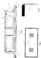
- Fig. 2 shows a view of the first embodiment of the acoustic sail 1 from below.
- the acoustic element 2 has a rectangular, the space-facing basic shape and is cuboid.
- other basic forms are conceivable, for example single or multi-part designs, rounded, oval, round or polygonal basic shapes.
- other geometric shapes of the acoustic element 2 in place of the cuboid shape such as pyramidal, cylindrical, prismatic, ovoid or spherical shapes are possible.
- spherical shapes for example, an arrangement of many spherical individual elements in a spatial plane is possible to form the area extending acoustic element 2.
- Such a design is possible with a variety of individual elements, which may also have different geometric shapes and do not have to be in exactly the same room level. As mentioned, it is only necessary for the acoustic element 2 to extend over a flat area.
- the LED strips 5 run straight in the longitudinal direction of the acoustic element 2 and are equally spaced from each other.
- the LEDs 3 are mounted on the LED strips 5 at the same distance from each other as the LED strips 5 are spaced from each other. This allows a uniform arrangement of the LEDs 3 on the acoustic element 2 and allows uniform illumination of the veneer 4.
- this type of LED lighting ensures that only a small part of the room facing side of the acoustic element 2 is covered by the LEDs ,
- the LEDs can be arranged such that the individual light cones on the veneer do not overlap, so that a uniform illumination is ensured. Alternatively, they may be arranged so that a plurality of light cones overlap such that a uniform illumination of the veneer 4 is ensured.
- the LEDs 3 can also be controlled differently (different light output). Also, they can be arranged so that desired light patterns arise on the veneer. These patterns can also be controlled by a light control unit, which is located, for example, in the basic unit 6.
- Fig. 3 shows a side view of the first embodiment of the acoustic sail 1 in the folded position.
- the hinge is used for hinged attachment of the acoustic sail 1 to the base unit 6. It is not mounted on the edge of the acoustic sail 1 in the illustrated embodiment, but lies on its (the space facing away) top and is moved in the direction of the center of the acoustic sail. Thus, it is arranged for the viewer, who sees the room facing side, hidden.
- the folding can be useful in particular for maintenance purposes, if access to the side facing away from the room of the acoustic sail 1 is required.
- the acoustic sail 1 is mounted hinged down along an axis extending parallel to its longitudinal axis by the hinge.
- another fastening element is arranged on the acoustic sail 1, which is arranged at a distance from the hinge on the acoustic sail 1 (in FIG Fig. 3 shown as a survey at the bottom left of the acoustic sail 1).
- the fastening means 7 (here the hinge) is attached to the base unit 6. In the illustrated embodiment, it is attached to a side surface of the base unit 6 and opposite to the spatial direction of the basic device 6 final, the space-facing side (spaced in the direction of the ceiling of the lower edge of the side of the base unit 6). This allows a flat contact between the acoustic sail 1 and the Basic unit 6, if the former is folded (in operating position). In this way, a connection of the first air space 9 can be made possible with an air outlet opening of the base unit 6. This can also prevent the view and access to parts lying in the basic device.
- Fig. 4 shows a side view of a second embodiment of the acoustic sail 1.
- the second embodiment corresponds in most parts of the first embodiment, so that a description of the identical parts is omitted at this point.
- the large-area LEDs 3 are inserted into the acoustic element 2.
- the large-area LEDs 3 may also contain a plurality of individual parts, for example a plurality of individual luminous elements.
- the term LED is to be understood as meaning all substantially planar light sources, such as, for example, LEDs, OLEDs, LCDs, AMOLEDs, panels with one or more of the aforementioned bulbs, and others.
- the LEDs 3 can also be placed on the acoustic element 2.
- the acoustic sail 1 in the illustrated embodiment does not include a veneer. Instead, the LEDs 3 illuminate the room directly. For this purpose, they are attached to the space facing side of the acoustic element 2. However, a veneer may additionally be used if desired, for example the veneer described for the first embodiment. Also, the LEDs 3 can each be covered with a transparent cover plate. This can serve to protect the light units.
- the acoustic sail 1 of the second embodiment does not include a second airspace. Instead, the air which has passed through the first air space 9 may be discharged directly through the air outlet slots 11, as indicated by the arrows. This allows an even more compact design of the acoustic sail 1.
- Fig. 5 shows a view of the second embodiment of the acoustic sail 1 from below.
- two LEDs 3 are in the acoustic element 2 introduced.
- the two LEDs 3 are arranged symmetrically on the rectangular acoustic element 2.
- the dark edge around the acoustic element 2 corresponds to the Lucasauslassschlitzen 11 which surround the acoustic element 2 frame-shaped completely in the illustrated embodiment.
- the air outlet slots 11 There are also other possible arrangements of the air outlet slots 11 conceivable. Thus, for example, they can be introduced at several points of the acoustic element 2, enclose the acoustic element 2 only partially in the shape of a frame, or break through the acoustic element 2 along one or more axes.
- Fig. 6 shows a side view of the second embodiment of the acoustic sail 1 in the folded position.
- the same arrangement of the fastener 7 is used on the acoustic sail 1 and the base 6, which has been described above for the first embodiment.
Applications Claiming Priority (1)
| Application Number | Priority Date | Filing Date | Title |
|---|---|---|---|
| DE202017102765.1U DE202017102765U1 (de) | 2017-05-09 | 2017-05-09 | Akustiksegel mit LEDs |
Publications (2)
| Publication Number | Publication Date |
|---|---|
| EP3401459A1 true EP3401459A1 (fr) | 2018-11-14 |
| EP3401459B1 EP3401459B1 (fr) | 2020-01-22 |
Family
ID=59295621
Family Applications (1)
| Application Number | Title | Priority Date | Filing Date |
|---|---|---|---|
| EP18169495.1A Active EP3401459B1 (fr) | 2017-05-09 | 2018-04-26 | Voile acoustique à led |
Country Status (2)
| Country | Link |
|---|---|
| EP (1) | EP3401459B1 (fr) |
| DE (1) | DE202017102765U1 (fr) |
Citations (5)
| Publication number | Priority date | Publication date | Assignee | Title |
|---|---|---|---|---|
| US4232594A (en) * | 1978-07-27 | 1980-11-11 | United States Gypsum Company | Modular ceiling panel unit usable with air distribution systems |
| WO2004014102A1 (fr) * | 2002-08-06 | 2004-02-12 | Sheila Kennedy | Modules eclairants et insonorisants |
| DE102005038199A1 (de) | 2004-08-31 | 2006-03-02 | Manfred Grimm | Vorrichtung zur Klimatisierung eines Raumes, insbesondere Deckenpaneel oder Deckensegel |
| DE202005002504U1 (de) * | 2005-02-15 | 2006-06-29 | Lahme, Michael | Deckensegel |
| DE202008008896U1 (de) * | 2008-10-27 | 2010-03-18 | Pinta Acoustic Gmbh | Schaumstoffteil sowie hängend befestigter Schallabsorber |
-
2017
- 2017-05-09 DE DE202017102765.1U patent/DE202017102765U1/de active Active
-
2018
- 2018-04-26 EP EP18169495.1A patent/EP3401459B1/fr active Active
Patent Citations (5)
| Publication number | Priority date | Publication date | Assignee | Title |
|---|---|---|---|---|
| US4232594A (en) * | 1978-07-27 | 1980-11-11 | United States Gypsum Company | Modular ceiling panel unit usable with air distribution systems |
| WO2004014102A1 (fr) * | 2002-08-06 | 2004-02-12 | Sheila Kennedy | Modules eclairants et insonorisants |
| DE102005038199A1 (de) | 2004-08-31 | 2006-03-02 | Manfred Grimm | Vorrichtung zur Klimatisierung eines Raumes, insbesondere Deckenpaneel oder Deckensegel |
| DE202005002504U1 (de) * | 2005-02-15 | 2006-06-29 | Lahme, Michael | Deckensegel |
| DE202008008896U1 (de) * | 2008-10-27 | 2010-03-18 | Pinta Acoustic Gmbh | Schaumstoffteil sowie hängend befestigter Schallabsorber |
Also Published As
| Publication number | Publication date |
|---|---|
| EP3401459B1 (fr) | 2020-01-22 |
| DE202017102765U1 (de) | 2017-06-19 |
Similar Documents
| Publication | Publication Date | Title |
|---|---|---|
| DE102008044956B4 (de) | Beleuchtungsvorrichtung zum Einbau in eine Platte | |
| EP1154200A2 (fr) | Distributeur de lumière pour un système d'éclairage, système d'éclairage et utilisation d' un système d'éclairage | |
| EP1586814A2 (fr) | Système d'éclairage | |
| DE202006014352U1 (de) | Leuchte mit wenigstens einer lichtdurchlässigen Abdeckung | |
| DE102010062454A1 (de) | Anordnung zur Lichtabgabe | |
| WO2012025210A1 (fr) | Dispositif d'éclairage, en particulier éclairage mural et/ou de plafond | |
| EP2184628A2 (fr) | Lampe, notamment lampe d'urgence, de sauvetage ou de sécurité | |
| DE202012103430U1 (de) | Flachleuchte | |
| DE202009000344U1 (de) | Beleuchtungsvorrichtung | |
| DE102011057097A1 (de) | Decken-Beleuchtungsanordnung | |
| AT14322U1 (de) | Beleuchtungssystem | |
| DE202009001048U1 (de) | Leuchte, insbesondere Not- oder Sicherheitsleuchte | |
| EP3401459B1 (fr) | Voile acoustique à led | |
| EP2330344A2 (fr) | Dispositif d'éclairage modifiable | |
| DE202013010375U1 (de) | Beleuchtungsvorrichtung für ein Patientenzimmer und Beleuchtungssystem | |
| DE202008014775U1 (de) | Sicherheits- oder Rettungszeichenleuchte | |
| DE102010063750B4 (de) | Dunstabzugshaube mit Leuchtmodul | |
| EP2557355A2 (fr) | Dispositif d éclairage | |
| DE202012103474U1 (de) | LED-Leuchte | |
| WO2009000692A1 (fr) | Appareil frigorifique comportant un groupe de ventilation | |
| EP2360420B1 (fr) | Système de lampes modulaire pour diodes électro luminescentes | |
| EP3853516A1 (fr) | Lampe destinée à être montée dans un plafond | |
| EP2267361A1 (fr) | Plaquette | |
| DE4440135C2 (de) | Leuchte mit einer Entblendungs- und Lichtlenkeinrichtung | |
| EP3984566B1 (fr) | Dispositif d'éclairage d'hygiène |
Legal Events
| Date | Code | Title | Description |
|---|---|---|---|
| PUAI | Public reference made under article 153(3) epc to a published international application that has entered the european phase |
Free format text: ORIGINAL CODE: 0009012 |
|
| STAA | Information on the status of an ep patent application or granted ep patent |
Free format text: STATUS: THE APPLICATION HAS BEEN PUBLISHED |
|
| AK | Designated contracting states |
Kind code of ref document: A1 Designated state(s): AL AT BE BG CH CY CZ DE DK EE ES FI FR GB GR HR HU IE IS IT LI LT LU LV MC MK MT NL NO PL PT RO RS SE SI SK SM TR |
|
| AX | Request for extension of the european patent |
Extension state: BA ME |
|
| STAA | Information on the status of an ep patent application or granted ep patent |
Free format text: STATUS: REQUEST FOR EXAMINATION WAS MADE |
|
| 17P | Request for examination filed |
Effective date: 20190514 |
|
| RBV | Designated contracting states (corrected) |
Designated state(s): AL AT BE BG CH CY CZ DE DK EE ES FI FR GB GR HR HU IE IS IT LI LT LU LV MC MK MT NL NO PL PT RO RS SE SI SK SM TR |
|
| GRAP | Despatch of communication of intention to grant a patent |
Free format text: ORIGINAL CODE: EPIDOSNIGR1 |
|
| RIC1 | Information provided on ipc code assigned before grant |
Ipc: E04B 9/00 20060101AFI20190718BHEP Ipc: F21Y 113/13 20160101ALN20190718BHEP Ipc: E04B 9/04 20060101ALN20190718BHEP Ipc: F21S 10/02 20060101ALI20190718BHEP Ipc: F21Y 115/10 20160101ALN20190718BHEP Ipc: F21Y 115/15 20160101ALN20190718BHEP Ipc: F21V 23/04 20060101ALN20190718BHEP Ipc: F21V 33/00 20060101ALI20190718BHEP Ipc: E04B 9/02 20060101ALI20190718BHEP |
|
| STAA | Information on the status of an ep patent application or granted ep patent |
Free format text: STATUS: GRANT OF PATENT IS INTENDED |
|
| INTG | Intention to grant announced |
Effective date: 20190822 |
|
| GRAS | Grant fee paid |
Free format text: ORIGINAL CODE: EPIDOSNIGR3 |
|
| GRAA | (expected) grant |
Free format text: ORIGINAL CODE: 0009210 |
|
| STAA | Information on the status of an ep patent application or granted ep patent |
Free format text: STATUS: THE PATENT HAS BEEN GRANTED |
|
| AK | Designated contracting states |
Kind code of ref document: B1 Designated state(s): AL AT BE BG CH CY CZ DE DK EE ES FI FR GB GR HR HU IE IS IT LI LT LU LV MC MK MT NL NO PL PT RO RS SE SI SK SM TR |
|
| REG | Reference to a national code |
Ref country code: GB Ref legal event code: FG4D Free format text: NOT ENGLISH |
|
| REG | Reference to a national code |
Ref country code: CH Ref legal event code: EP |
|
| REG | Reference to a national code |
Ref country code: AT Ref legal event code: REF Ref document number: 1226987 Country of ref document: AT Kind code of ref document: T Effective date: 20200215 |
|
| REG | Reference to a national code |
Ref country code: IE Ref legal event code: FG4D Free format text: LANGUAGE OF EP DOCUMENT: GERMAN |
|
| REG | Reference to a national code |
Ref country code: DE Ref legal event code: R096 Ref document number: 502018000648 Country of ref document: DE |
|
| REG | Reference to a national code |
Ref country code: CH Ref legal event code: NV Representative=s name: RIEDERER HASLER AND PARTNER PATENTANWAELTE AG, LI |
|
| REG | Reference to a national code |
Ref country code: NL Ref legal event code: MP Effective date: 20200122 |
|
| REG | Reference to a national code |
Ref country code: LT Ref legal event code: MG4D |
|
| PG25 | Lapsed in a contracting state [announced via postgrant information from national office to epo] |
Ref country code: RS Free format text: LAPSE BECAUSE OF FAILURE TO SUBMIT A TRANSLATION OF THE DESCRIPTION OR TO PAY THE FEE WITHIN THE PRESCRIBED TIME-LIMIT Effective date: 20200122 Ref country code: NO Free format text: LAPSE BECAUSE OF FAILURE TO SUBMIT A TRANSLATION OF THE DESCRIPTION OR TO PAY THE FEE WITHIN THE PRESCRIBED TIME-LIMIT Effective date: 20200422 Ref country code: FI Free format text: LAPSE BECAUSE OF FAILURE TO SUBMIT A TRANSLATION OF THE DESCRIPTION OR TO PAY THE FEE WITHIN THE PRESCRIBED TIME-LIMIT Effective date: 20200122 Ref country code: PT Free format text: LAPSE BECAUSE OF FAILURE TO SUBMIT A TRANSLATION OF THE DESCRIPTION OR TO PAY THE FEE WITHIN THE PRESCRIBED TIME-LIMIT Effective date: 20200614 Ref country code: NL Free format text: LAPSE BECAUSE OF FAILURE TO SUBMIT A TRANSLATION OF THE DESCRIPTION OR TO PAY THE FEE WITHIN THE PRESCRIBED TIME-LIMIT Effective date: 20200122 |
|
| PG25 | Lapsed in a contracting state [announced via postgrant information from national office to epo] |
Ref country code: LV Free format text: LAPSE BECAUSE OF FAILURE TO SUBMIT A TRANSLATION OF THE DESCRIPTION OR TO PAY THE FEE WITHIN THE PRESCRIBED TIME-LIMIT Effective date: 20200122 Ref country code: SE Free format text: LAPSE BECAUSE OF FAILURE TO SUBMIT A TRANSLATION OF THE DESCRIPTION OR TO PAY THE FEE WITHIN THE PRESCRIBED TIME-LIMIT Effective date: 20200122 Ref country code: HR Free format text: LAPSE BECAUSE OF FAILURE TO SUBMIT A TRANSLATION OF THE DESCRIPTION OR TO PAY THE FEE WITHIN THE PRESCRIBED TIME-LIMIT Effective date: 20200122 Ref country code: IS Free format text: LAPSE BECAUSE OF FAILURE TO SUBMIT A TRANSLATION OF THE DESCRIPTION OR TO PAY THE FEE WITHIN THE PRESCRIBED TIME-LIMIT Effective date: 20200522 Ref country code: BG Free format text: LAPSE BECAUSE OF FAILURE TO SUBMIT A TRANSLATION OF THE DESCRIPTION OR TO PAY THE FEE WITHIN THE PRESCRIBED TIME-LIMIT Effective date: 20200422 Ref country code: GR Free format text: LAPSE BECAUSE OF FAILURE TO SUBMIT A TRANSLATION OF THE DESCRIPTION OR TO PAY THE FEE WITHIN THE PRESCRIBED TIME-LIMIT Effective date: 20200423 |
|
| REG | Reference to a national code |
Ref country code: DE Ref legal event code: R097 Ref document number: 502018000648 Country of ref document: DE |
|
| PG25 | Lapsed in a contracting state [announced via postgrant information from national office to epo] |
Ref country code: SK Free format text: LAPSE BECAUSE OF FAILURE TO SUBMIT A TRANSLATION OF THE DESCRIPTION OR TO PAY THE FEE WITHIN THE PRESCRIBED TIME-LIMIT Effective date: 20200122 Ref country code: RO Free format text: LAPSE BECAUSE OF FAILURE TO SUBMIT A TRANSLATION OF THE DESCRIPTION OR TO PAY THE FEE WITHIN THE PRESCRIBED TIME-LIMIT Effective date: 20200122 Ref country code: LT Free format text: LAPSE BECAUSE OF FAILURE TO SUBMIT A TRANSLATION OF THE DESCRIPTION OR TO PAY THE FEE WITHIN THE PRESCRIBED TIME-LIMIT Effective date: 20200122 Ref country code: ES Free format text: LAPSE BECAUSE OF FAILURE TO SUBMIT A TRANSLATION OF THE DESCRIPTION OR TO PAY THE FEE WITHIN THE PRESCRIBED TIME-LIMIT Effective date: 20200122 Ref country code: DK Free format text: LAPSE BECAUSE OF FAILURE TO SUBMIT A TRANSLATION OF THE DESCRIPTION OR TO PAY THE FEE WITHIN THE PRESCRIBED TIME-LIMIT Effective date: 20200122 Ref country code: CZ Free format text: LAPSE BECAUSE OF FAILURE TO SUBMIT A TRANSLATION OF THE DESCRIPTION OR TO PAY THE FEE WITHIN THE PRESCRIBED TIME-LIMIT Effective date: 20200122 Ref country code: EE Free format text: LAPSE BECAUSE OF FAILURE TO SUBMIT A TRANSLATION OF THE DESCRIPTION OR TO PAY THE FEE WITHIN THE PRESCRIBED TIME-LIMIT Effective date: 20200122 Ref country code: SM Free format text: LAPSE BECAUSE OF FAILURE TO SUBMIT A TRANSLATION OF THE DESCRIPTION OR TO PAY THE FEE WITHIN THE PRESCRIBED TIME-LIMIT Effective date: 20200122 |
|
| PLBE | No opposition filed within time limit |
Free format text: ORIGINAL CODE: 0009261 |
|
| STAA | Information on the status of an ep patent application or granted ep patent |
Free format text: STATUS: NO OPPOSITION FILED WITHIN TIME LIMIT |
|
| PG25 | Lapsed in a contracting state [announced via postgrant information from national office to epo] |
Ref country code: MC Free format text: LAPSE BECAUSE OF FAILURE TO SUBMIT A TRANSLATION OF THE DESCRIPTION OR TO PAY THE FEE WITHIN THE PRESCRIBED TIME-LIMIT Effective date: 20200122 |
|
| 26N | No opposition filed |
Effective date: 20201023 |
|
| PG25 | Lapsed in a contracting state [announced via postgrant information from national office to epo] |
Ref country code: LU Free format text: LAPSE BECAUSE OF NON-PAYMENT OF DUE FEES Effective date: 20200426 Ref country code: FR Free format text: LAPSE BECAUSE OF NON-PAYMENT OF DUE FEES Effective date: 20200430 Ref country code: IT Free format text: LAPSE BECAUSE OF FAILURE TO SUBMIT A TRANSLATION OF THE DESCRIPTION OR TO PAY THE FEE WITHIN THE PRESCRIBED TIME-LIMIT Effective date: 20200122 |
|
| REG | Reference to a national code |
Ref country code: BE Ref legal event code: MM Effective date: 20200430 |
|
| PG25 | Lapsed in a contracting state [announced via postgrant information from national office to epo] |
Ref country code: SI Free format text: LAPSE BECAUSE OF FAILURE TO SUBMIT A TRANSLATION OF THE DESCRIPTION OR TO PAY THE FEE WITHIN THE PRESCRIBED TIME-LIMIT Effective date: 20200122 Ref country code: PL Free format text: LAPSE BECAUSE OF FAILURE TO SUBMIT A TRANSLATION OF THE DESCRIPTION OR TO PAY THE FEE WITHIN THE PRESCRIBED TIME-LIMIT Effective date: 20200122 Ref country code: BE Free format text: LAPSE BECAUSE OF NON-PAYMENT OF DUE FEES Effective date: 20200430 |
|
| PG25 | Lapsed in a contracting state [announced via postgrant information from national office to epo] |
Ref country code: IE Free format text: LAPSE BECAUSE OF NON-PAYMENT OF DUE FEES Effective date: 20200426 |
|
| PG25 | Lapsed in a contracting state [announced via postgrant information from national office to epo] |
Ref country code: TR Free format text: LAPSE BECAUSE OF FAILURE TO SUBMIT A TRANSLATION OF THE DESCRIPTION OR TO PAY THE FEE WITHIN THE PRESCRIBED TIME-LIMIT Effective date: 20200122 Ref country code: MT Free format text: LAPSE BECAUSE OF FAILURE TO SUBMIT A TRANSLATION OF THE DESCRIPTION OR TO PAY THE FEE WITHIN THE PRESCRIBED TIME-LIMIT Effective date: 20200122 Ref country code: CY Free format text: LAPSE BECAUSE OF FAILURE TO SUBMIT A TRANSLATION OF THE DESCRIPTION OR TO PAY THE FEE WITHIN THE PRESCRIBED TIME-LIMIT Effective date: 20200122 |
|
| PG25 | Lapsed in a contracting state [announced via postgrant information from national office to epo] |
Ref country code: MK Free format text: LAPSE BECAUSE OF FAILURE TO SUBMIT A TRANSLATION OF THE DESCRIPTION OR TO PAY THE FEE WITHIN THE PRESCRIBED TIME-LIMIT Effective date: 20200122 Ref country code: AL Free format text: LAPSE BECAUSE OF FAILURE TO SUBMIT A TRANSLATION OF THE DESCRIPTION OR TO PAY THE FEE WITHIN THE PRESCRIBED TIME-LIMIT Effective date: 20200122 |
|
| P01 | Opt-out of the competence of the unified patent court (upc) registered |
Effective date: 20230515 |
|
| PGFP | Annual fee paid to national office [announced via postgrant information from national office to epo] |
Ref country code: DE Payment date: 20230420 Year of fee payment: 6 Ref country code: CH Payment date: 20230502 Year of fee payment: 6 |
|
| PGFP | Annual fee paid to national office [announced via postgrant information from national office to epo] |
Ref country code: AT Payment date: 20230420 Year of fee payment: 6 |
|
| PGFP | Annual fee paid to national office [announced via postgrant information from national office to epo] |
Ref country code: GB Payment date: 20230419 Year of fee payment: 6 |