EP3401268A1 - Diagnostic step for a passenger conveyor - Google Patents
Diagnostic step for a passenger conveyor Download PDFInfo
- Publication number
- EP3401268A1 EP3401268A1 EP18153256.5A EP18153256A EP3401268A1 EP 3401268 A1 EP3401268 A1 EP 3401268A1 EP 18153256 A EP18153256 A EP 18153256A EP 3401268 A1 EP3401268 A1 EP 3401268A1
- Authority
- EP
- European Patent Office
- Prior art keywords
- passenger conveyor
- lateral side
- diagnostic step
- camera
- data
- Prior art date
- Legal status (The legal status is an assumption and is not a legal conclusion. Google has not performed a legal analysis and makes no representation as to the accuracy of the status listed.)
- Granted
Links
Images





Classifications
-
- B—PERFORMING OPERATIONS; TRANSPORTING
- B66—HOISTING; LIFTING; HAULING
- B66B—ELEVATORS; ESCALATORS OR MOVING WALKWAYS
- B66B23/00—Component parts of escalators or moving walkways
- B66B23/08—Carrying surfaces
- B66B23/12—Steps
-
- B—PERFORMING OPERATIONS; TRANSPORTING
- B66—HOISTING; LIFTING; HAULING
- B66B—ELEVATORS; ESCALATORS OR MOVING WALKWAYS
- B66B29/00—Safety devices of escalators or moving walkways
- B66B29/005—Applications of security monitors
-
- B—PERFORMING OPERATIONS; TRANSPORTING
- B66—HOISTING; LIFTING; HAULING
- B66B—ELEVATORS; ESCALATORS OR MOVING WALKWAYS
- B66B25/00—Control of escalators or moving walkways
- B66B25/006—Monitoring for maintenance or repair
Definitions
- This invention generally relates to passenger conveyors. More particularly, this invention relates to a diagnostic device which facilitates determining the cause of failure or malfunctions associated with a passenger conveyor.
- Passenger conveyors such as escalators, typically include a plurality of steps that travel around a loop for carrying passengers between landings, which may be located at different levels of a building. Occasionally, there is a need for maintenance or repair of the escalator.
- This process is both time-consuming and labor-intensive since it is difficult to pin point the components causing the sounds due to sound reverberations in the interior space of the escalator and since visual checks need to be done after shutting down the escalator and removing steps there from. The process also involves the risk of maintenance personnel being injured.
- a diagnostic step for a passenger conveyor comprises at least one camera for shooting at least one lateral side of the interior space of the passenger conveyor, at least one directional microphone pointed to said at least one lateral side of the interior space of the passenger conveyor and an analyzer unit which receives image data from the camera and sound data from the directional microphone and transmits the data to an outside network.
- Particular embodiments may include any of the following optional features, alone or in combination:
- the diagnostic step further may compris at least one partition for separating sounds emanating from the first lateral side and the second lateral side.
- the diagnostic step further may have a step-like configuration comprising a rise portion and a tread portion, the camera, directional microphone and analyzer unit positioned in the space defined by the rise portion and the tread portion.
- the tread portion may include at least one maintenance window.
- the camera and the directional microphone may be adjustable through the maintenance window.
- the diagnostic step further may comprise an acceleration sensor.
- the analyzer unit may receive acceleration data from the acceleration sensor and transmits the data to the outside network.
- the diagnostic step further may comprise a battery.
- the analyzer unit may comprise a wireless network interface including an antenna.
- the analyzer unit may include a memory for storing data and the analyzer unit may analyze the stored data to provide analyzed results to the outside network.
- the passenger conveyor may be an escalator.
- a method for performing maintenance or repair of a passenger conveyor using a diagnostic step comprising at least one camera and at least one directional microphone comprises removing a step from a passenger conveyor and installing the diagnostic step in place of the removed step, collecting image data from the camera of at least one lateral side of the interior space of the passenger conveyor while the passenger conveyor is operating, collecting sound data from the directional microphone of said at least one lateral side of the interior space of the passenger conveyor while the passenger conveyor is operating and transmitting the image data and the sound data to an outside network.
- Particular embodiments may include any of the following optional features, alone or in combination:
- the method further may comprise analyzing the data and providing the analyzed data to the outside network.
- the passenger conveyor may be an escalator.
- Fig. 1 schematically shows a passenger conveyer 1 in which the diagnostic device of the present invention may be used.
- the passenger conveyor 1 is an escalator including a plurality of escalator steps 2 that travel around a loop for carrying passengers between landings at different levels within a building.
- the example passenger conveyor 1 of Fig. 1 comprises a truss 3 installed between a lower landing 4 and an upper landing 5.
- a first sprocket wheel 6 is rotatably supported at an upper end of the truss 3 and a second sprocket wheel 7 is rotatably supported at a lower end of the truss 3.
- a drive system (not shown) rotates the first sprocket wheel 6 as well as a handrail drive sprocket 8.
- the handrail drive sprocket 8 is coupled to a pulley 9 which forms part of a handrail drive system 10.
- the escalator steps 2 are coupled to a step chain 12 which may include a plurality of rollers 13 connected by a plurality of links 14.
- the step chain 12 and the escalator steps 2 are driven by the drive system via the first sprocket wheel 6.
- a typical step chain 12 includes a pair of parallel endless loops on both lateral sides of the escalator steps 2. The loops are connected together by transverse axles (not shown) that pass between and help support the escalator steps 2.
- transverse axles not shown
- An endless handrail 15 passes around a balustrade assembly 16. While only a single handrail 15 is illustrated in Fig. 1 , it will be understood that a pair of endless handrails 15 are supported on a respective balustrade assembly 16 on both lateral sides of the escalator steps 2 and are each driven by a respective handrail drive system 10 positioned in the interior space of the truss 3 on each lateral side thereof.
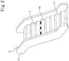
- Fig. 2 shows an example diagnostic device 18 of the present invention in the form of a step.
- the diagnostic step 18 may be simply installed on the escalator during maintenance or repair by removing a single escalator step 2 and attaching the diagnostic step 18 in place of the removed escalator step 2.
- the diagnostic step 18 may have a configuration which resembles escalator step 2 and includes a tread portion 19 joined to a riser portion 20 and step arms 21 (only one shown in Fig. 3 ) connecting the tread portion 19 to the riser portion 20 as known in the art.
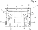
- the step arms 21 are connected to each other by an axle 24 ( Fig. 4 ) and may each comprise rollers 22 on one end for riding on a rail and support members 23 on the other end for engaging a transverse axle such that the diagnostic step 18 may be driven around the loop together with the escalator steps 2 when it is installed on the escalator.
- Fig. 3(a) shows a plan view
- Fig. 3(b) shows a front view
- Fig. 3(c) shows a side view of the diagnostic step 18.
- the outer surface 19a of the tread portion 19 corresponds to the surface of escalator step 2 which receives the foot of a passenger and faces generally upward during the advance path.
- the tread portion 19 includes at least one maintenance window 25 (three in this example) for access to the inner side of the diagnostic step 18.
- the diagnostic step 18 includes at least one camera 26, at least one directional microphone 28 and an analyzer unit 29 in the space defined by the tread portion 19, riser portion 20 and step arms 21.
- the diagnostic step 18 includes two cameras 26 and two microphones 28.
- Each camera 26 may be attached to the inner surface 19b of the tread portion 19 such as by brackets and may be adjustable to shoot different directions.
- Each camera 26 may include a LED light.
- one camera is adjusted to shoot one or a plurality of components positioned on one lateral side (ex. the left-hand side of Fig. 2 ) and one camera is adjusted to shoot one or a plurality of components positioned on the other lateral side (ex. the right-hand side of Fig.
- the directional microphones 28 may also be attached to the inner surface 19b of the tread portion 19 such as by brackets and may be adjustable to point to different directions. In this embodiment, one microphone 28 is adjusted to point to one or a plurality of components on the right-hand side and one microphone 28 is adjusted to point to one or a plurality of components positioned on the left-hand side of the interior space of the truss 3.
- the cameras 26 and the microphones 28 may collect images or sounds of components positioned on the left-hand side and on the right-hand side separately.
- Such components may include components such as the handrail drive system 10 or sprocket wheels 6, 7.
- the cameras 26 and the microphones 28 may be adjusted through the maintenance windows 25 after installing the diagnostic step 18 onto the escalator.
- the analyzer unit 29 may be attached to the inner surface 19b of the tread portion 19. A detailed view of the analyzer unit 29 is shown in Fig. 5 .
- the analyzer unit 29 may comprise a printed-circuit board 30 including a memory 31, a wireless network interface device 32 such as a 3G modem, WiFi interface etc. including an antenna 34 and a battery 35 for providing power to all of the components included in the diagnostic step 18.
- the directional microphones 28 and cameras 26 are connected to the printed-circuit board 30 to provide sound data and image data.
- An acceleration sensor 36 may also be connected to the printed-circuit board to provide acceleration data.
- the printed-circuit board 29 receives the analog data or digital data from the cameras 26, microphones 28 and sensor 36, converts analog data to digital data as necessary and stores such data in the memory 31. The sound data and image data are synchronized.
- the printed-circuit board 29 may further analyze such data. Data and analyzed results may be provided to a wireless network 38 ( figures 7 to 9 ) via the wireless network interface device 32.
- the camera 26 itself may include a memory or storage such as a SD card and a wireless network interface device such as a WiFi interface. Image data may be stored in the memory or storage and will be directly accessible through a wireless network.
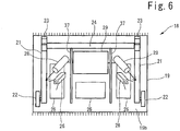
- Fig. 6 shows a further embodiment in which partitions 37 are provided on the inside surface 19b of the tread portion 19 to separate sounds emanating from the right-hand side of the truss and sounds emanating from the left-hand side of the truss to allow a more precise collection of sounds.
- Two partitions 37 are provided in this embodiment. However, one partition 37 may be sufficient to separate sounds in other embodiments.
- data may be transmitted to a personal computer 40 which may be in the form of a tablet, smart phone etc. via the wireless network 38.
- a service engineer may listen to the sounds emanating from the left-hand side of the truss 3 while viewing the corresponding image of the components positioned on the left-hand side of the truss 3 causing the sounds.
- the sounds and image may be switched to the right-hand side after checking the left-hand side. This allows the service engineer to easily find out which components, components positioned on the left-hand side or components positioned on the right-hand side, are causing abnormal sounds, in spite of sound reverberations inside the truss 3 and also allows the service engineer to visually check the components causing the abnormal sounds at the same time. This greatly shortens the time to determine the cause of failure or malfunctions associated with the escalator and does not require stopping the escalator and gaining access to the space beneath the escalator steps 2.
- Fig. 8 shows another embodiment in which the analyzer unit 29 analyzes data from the microphone 28, camera 26 and/or sensor 36 and the analyzed results are transmitted to the personal computer 40 of the service engineer.
- the analyzed results may include the detection of abnormal sounds with corresponding images and may allow the service engineer to immediately determine the cause of failure or malfunctions associated with the escalator.
- the service engineer may upload such results to a server 42 for storage.
- the server 42 may be remote from the site and the stored data may be used for preventive maintenance. This process is carried out via a wireless network 38.
- Fig. 9 shows a further embodiment in which data and/or analyzed data is transmitted to a server 42.
- the server 42 may be remote from the site.
- the data is stored and may be further analyzed in the server 42.
- the stored data may be used for preventive maintenance.
- the server 42 may provide the further analyzed results to the personal computer 40 of the service engineer. This process is also carried out via a wireless network 38.
Landscapes
- Escalators And Moving Walkways (AREA)
- Vehicle Cleaning, Maintenance, Repair, Refitting, And Outriggers (AREA)
Abstract
Description
- This invention generally relates to passenger conveyors. More particularly, this invention relates to a diagnostic device which facilitates determining the cause of failure or malfunctions associated with a passenger conveyor.
- Passenger conveyors, such as escalators, typically include a plurality of steps that travel around a loop for carrying passengers between landings, which may be located at different levels of a building. Occasionally, there is a need for maintenance or repair of the escalator.
- During maintenance or repair, operating sounds are usually checked to determine if the escalator is operating in a normal condition. If there are any abnormal sounds, a conventional maintenance or repair process will involve making an educated guess of the components causing the sounds, and removing a plurality of steps from the escalator to gain access to a space beneath the steps to visually check such components in order to determine the cause of failure or malfunctions associated with the escalator.
- This process is both time-consuming and labor-intensive since it is difficult to pin point the components causing the sounds due to sound reverberations in the interior space of the escalator and since visual checks need to be done after shutting down the escalator and removing steps there from. The process also involves the risk of maintenance personnel being injured.
- In view of the above and other considerations, there is a need for a diagnostic device which facilitates determining the cause of failure or malfunctions associated with a passenger conveyor.
- According to one embodiment of the invention, a diagnostic step for a passenger conveyor comprises at least one camera for shooting at least one lateral side of the interior space of the passenger conveyor, at least one directional microphone pointed to said at least one lateral side of the interior space of the passenger conveyor and an analyzer unit which receives image data from the camera and sound data from the directional microphone and transmits the data to an outside network.
- Particular embodiments may include any of the following optional features, alone or in combination:
- The at least one camera may comprise two cameras with one camera shooting a first lateral side of the interior space of the passenger conveyor and the other camera shooting a second lateral side of the interior space of the passenger conveyor opposed to the first lateral side. Moreover, the at least one directional microphone may comprise two microphones with one microphone pointed to the first lateral side of the interior space of the passenger conveyor and the other microphone pointed to the second lateral side of the interior space of the passenger conveyor.
- The diagnostic step further may compris at least one partition for separating sounds emanating from the first lateral side and the second lateral side.
- The diagnostic step further may have a step-like configuration comprising a rise portion and a tread portion, the camera, directional microphone and analyzer unit positioned in the space defined by the rise portion and the tread portion.
- The tread portion may include at least one maintenance window.
- The camera and the directional microphone may be adjustable through the maintenance window.
- The diagnostic step further may comprise an acceleration sensor. The analyzer unit may receive acceleration data from the acceleration sensor and transmits the data to the outside network.
- The diagnostic step further may comprise a battery.
- The analyzer unit may comprise a wireless network interface including an antenna.
- The analyzer unit may include a memory for storing data and the analyzer unit may analyze the stored data to provide analyzed results to the outside network.
- The passenger conveyor may be an escalator.
- According to another embodiment of the invention, a method for performing maintenance or repair of a passenger conveyor using a diagnostic step comprising at least one camera and at least one directional microphone comprises removing a step from a passenger conveyor and installing the diagnostic step in place of the removed step, collecting image data from the camera of at least one lateral side of the interior space of the passenger conveyor while the passenger conveyor is operating, collecting sound data from the directional microphone of said at least one lateral side of the interior space of the passenger conveyor while the passenger conveyor is operating and transmitting the image data and the sound data to an outside network.
- Particular embodiments may include any of the following optional features, alone or in combination:
- The method further may comprise adjusting the camera and the microphone to shoot or point to at least one component positioned on said at least one lateral side of the interior space of the passenger conveyor.
- The method further may comprise analyzing the data and providing the analyzed data to the outside network.
- The passenger conveyor may be an escalator.
- The detailed description explains embodiments of the invention, together with advantages and features, by way of example with reference to the drawings.
-
Fig. 1 is a cross-sectional diagram of an escalator. -
Fig. 2 is a schematic view of an escalator with the diagnostic step of the present invention installed thereon. -
Fig. 3(a) is a plan view,Fig. 3(b) is a front view andFig. 3(c) is a side view of the diagnostic step ofFig. 2 . -
Fig. 4 is a bottom view of the diagnostic step ofFig. 2 . -
Fig. 5 is a detailed view of the analyzer unit ofFig. 4 . -
Fig. 6 is a bottom view of another embodiment of the diagnostic step of the present invention. -
Fig. 7 is a schematic view of a wireless network connecting the analyzer unit and a personal computer. -
Fig. 8 is a schematic view of a wireless network connecting the analyzer unit, a personal computer and a server. -
Fig. 9 is a schematic view of another example wireless network connecting the analyzer unit, a personal computer and a server. -
Fig. 1 schematically shows apassenger conveyer 1 in which the diagnostic device of the present invention may be used. In this example, thepassenger conveyor 1 is an escalator including a plurality ofescalator steps 2 that travel around a loop for carrying passengers between landings at different levels within a building. - The
example passenger conveyor 1 ofFig. 1 comprises a truss 3 installed between a lower landing 4 and anupper landing 5. Afirst sprocket wheel 6 is rotatably supported at an upper end of the truss 3 and a second sprocket wheel 7 is rotatably supported at a lower end of the truss 3. A drive system (not shown) rotates thefirst sprocket wheel 6 as well as ahandrail drive sprocket 8. Thehandrail drive sprocket 8 is coupled to a pulley 9 which forms part of ahandrail drive system 10. - The
escalator steps 2 are coupled to astep chain 12 which may include a plurality ofrollers 13 connected by a plurality oflinks 14. Thestep chain 12 and theescalator steps 2 are driven by the drive system via thefirst sprocket wheel 6. Atypical step chain 12 includes a pair of parallel endless loops on both lateral sides of theescalator steps 2. The loops are connected together by transverse axles (not shown) that pass between and help support theescalator steps 2. Thus, while only a single loop is illustrated inFig. 1 , it will be understood that the escalator includes dual loops, and eachstep chain 12 is driven aroundrespective sprocket wheels 6, 7 positioned in the interior space of the truss 3 on each lateral side thereof. - An
endless handrail 15 passes around abalustrade assembly 16. While only asingle handrail 15 is illustrated inFig. 1 , it will be understood that a pair ofendless handrails 15 are supported on arespective balustrade assembly 16 on both lateral sides of theescalator steps 2 and are each driven by a respectivehandrail drive system 10 positioned in the interior space of the truss 3 on each lateral side thereof. -
Fig. 2 shows an examplediagnostic device 18 of the present invention in the form of a step. Thediagnostic step 18 may be simply installed on the escalator during maintenance or repair by removing asingle escalator step 2 and attaching thediagnostic step 18 in place of the removedescalator step 2. - As shown in
Fig. 3 , thediagnostic step 18 may have a configuration which resemblesescalator step 2 and includes atread portion 19 joined to ariser portion 20 and step arms 21 (only one shown inFig. 3 ) connecting thetread portion 19 to theriser portion 20 as known in the art. Thestep arms 21 are connected to each other by an axle 24 (Fig. 4 ) and may each compriserollers 22 on one end for riding on a rail and supportmembers 23 on the other end for engaging a transverse axle such that thediagnostic step 18 may be driven around the loop together with theescalator steps 2 when it is installed on the escalator.Fig. 3(a) shows a plan view,Fig. 3(b) shows a front view andFig. 3(c) shows a side view of thediagnostic step 18. - The
outer surface 19a of thetread portion 19 corresponds to the surface ofescalator step 2 which receives the foot of a passenger and faces generally upward during the advance path. Thetread portion 19 includes at least one maintenance window 25 (three in this example) for access to the inner side of thediagnostic step 18. - The
diagnostic step 18 includes at least onecamera 26, at least onedirectional microphone 28 and ananalyzer unit 29 in the space defined by thetread portion 19,riser portion 20 andstep arms 21. In the embodiment shown inFig. 4 , thediagnostic step 18 includes twocameras 26 and twomicrophones 28. Eachcamera 26 may be attached to theinner surface 19b of thetread portion 19 such as by brackets and may be adjustable to shoot different directions. Eachcamera 26 may include a LED light. In this embodiment, one camera is adjusted to shoot one or a plurality of components positioned on one lateral side (ex. the left-hand side ofFig. 2 ) and one camera is adjusted to shoot one or a plurality of components positioned on the other lateral side (ex. the right-hand side ofFig. 2 ) of the interior space of the truss 3. Thedirectional microphones 28 may also be attached to theinner surface 19b of thetread portion 19 such as by brackets and may be adjustable to point to different directions. In this embodiment, onemicrophone 28 is adjusted to point to one or a plurality of components on the right-hand side and onemicrophone 28 is adjusted to point to one or a plurality of components positioned on the left-hand side of the interior space of the truss 3. - In this way, the
cameras 26 and themicrophones 28 may collect images or sounds of components positioned on the left-hand side and on the right-hand side separately. Such components may include components such as thehandrail drive system 10 orsprocket wheels 6, 7. Thecameras 26 and themicrophones 28 may be adjusted through themaintenance windows 25 after installing thediagnostic step 18 onto the escalator. - The
analyzer unit 29 may be attached to theinner surface 19b of thetread portion 19. A detailed view of theanalyzer unit 29 is shown inFig. 5 . Theanalyzer unit 29 may comprise a printed-circuit board 30 including amemory 31, a wirelessnetwork interface device 32 such as a 3G modem, WiFi interface etc. including anantenna 34 and abattery 35 for providing power to all of the components included in thediagnostic step 18. Thedirectional microphones 28 andcameras 26 are connected to the printed-circuit board 30 to provide sound data and image data. Anacceleration sensor 36 may also be connected to the printed-circuit board to provide acceleration data. The printed-circuit board 29 receives the analog data or digital data from thecameras 26,microphones 28 andsensor 36, converts analog data to digital data as necessary and stores such data in thememory 31. The sound data and image data are synchronized. The printed-circuit board 29 may further analyze such data. Data and analyzed results may be provided to a wireless network 38 (figures 7 to 9 ) via the wirelessnetwork interface device 32. - In another embodiment, the
camera 26 itself may include a memory or storage such as a SD card and a wireless network interface device such as a WiFi interface. Image data may be stored in the memory or storage and will be directly accessible through a wireless network. -
Fig. 6 shows a further embodiment in whichpartitions 37 are provided on theinside surface 19b of thetread portion 19 to separate sounds emanating from the right-hand side of the truss and sounds emanating from the left-hand side of the truss to allow a more precise collection of sounds. Twopartitions 37 are provided in this embodiment. However, onepartition 37 may be sufficient to separate sounds in other embodiments. - With reference to
Fig. 7 , data may be transmitted to apersonal computer 40 which may be in the form of a tablet, smart phone etc. via thewireless network 38. A service engineer may listen to the sounds emanating from the left-hand side of the truss 3 while viewing the corresponding image of the components positioned on the left-hand side of the truss 3 causing the sounds. The sounds and image may be switched to the right-hand side after checking the left-hand side. This allows the service engineer to easily find out which components, components positioned on the left-hand side or components positioned on the right-hand side, are causing abnormal sounds, in spite of sound reverberations inside the truss 3 and also allows the service engineer to visually check the components causing the abnormal sounds at the same time. This greatly shortens the time to determine the cause of failure or malfunctions associated with the escalator and does not require stopping the escalator and gaining access to the space beneath the escalator steps 2. -
Fig. 8 shows another embodiment in which theanalyzer unit 29 analyzes data from themicrophone 28,camera 26 and/orsensor 36 and the analyzed results are transmitted to thepersonal computer 40 of the service engineer. The analyzed results may include the detection of abnormal sounds with corresponding images and may allow the service engineer to immediately determine the cause of failure or malfunctions associated with the escalator. The service engineer may upload such results to aserver 42 for storage. Theserver 42 may be remote from the site and the stored data may be used for preventive maintenance. This process is carried out via awireless network 38. -
Fig. 9 shows a further embodiment in which data and/or analyzed data is transmitted to aserver 42. Theserver 42 may be remote from the site. The data is stored and may be further analyzed in theserver 42. The stored data may be used for preventive maintenance. Theserver 42 may provide the further analyzed results to thepersonal computer 40 of the service engineer. This process is also carried out via awireless network 38. - While the invention has been described in detail in connection with only a limited number of embodiments, it should be readily understood that the invention is not limited to such disclosed embodiments. Rather, the invention can be modified to incorporate any number of variations, alterations, substitutions or equivalent arrangements not heretofore described, but which are commensurate with the spirit and scope of the invention. Additionally, while various embodiments of the invention have been described, it is to be understood that aspects of the invention may include only some of the described embodiments. Accordingly, the invention is not to be seen as limited by the foregoing description, but is only limited by the scope of the appended claims.
Claims (15)
- A diagnostic step for a passenger conveyor, comprising:at least one camera for shooting at least one lateral side of the interior space of the passenger conveyor;at least one directional microphone pointed to said at least one lateral side of the interior space of the passenger conveyor; andan analyzer unit which receives image data from the camera and sound data from the directional microphone and transmits the data to an outside network.
- The diagnostic step of claim 1,wherein the at least one camera comprises two cameras with one camera shooting a first lateral side of the interior space of the passenger conveyor and the other camera shooting a second lateral side of the interior space of the passenger conveyor opposed to the first lateral side; andwherein the at least one directional microphone comprises two microphones with one microphone pointed to the first lateral side of the interior space of the passenger conveyor and the other microphone pointed to the second lateral side of the interior space of the passenger conveyor.
- The diagnostic step of claim 2, further comprising at least one partition for separating sounds emanating from the first lateral side and the second lateral side.
- The diagnostic step of any of claims 1 to 3, wherein the diagnostic step has a step-like configuration comprising a rise portion and a tread portion, the camera, directional microphone and analyzer unit positioned in the space defined by the rise portion and the tread portion.
- The diagnostic step of claim 4, wherein the tread portion includes at least one maintenance window.
- The diagnostic step of claim 5, wherein the camera and the directional microphone is adjustable through the maintenance window.
- The diagnostic step of any of claims 1 to 6, further comprising an acceleration sensor and wherein the analyzer unit receives acceleration data from the acceleration sensor and transmits the data to the outside network.
- The diagnostic step of any of claims 1 to 7, further comprising a battery.
- The diagnostic step of any of claims 1 to 8, wherein the analyzer unit comprises a wireless network interface including an antenna.
- The diagnostic step of any of claims 1 to 9, wherein the analyzer unit includes a memory for storing data and the analyzer unit analyzes the stored data to provide analyzed results to the outside network.
- The diagnostic step of any of claims 1 to 10, wherein the passenger conveyor is an escalator.
- A method for performing maintenance or repair of a passenger conveyor using a diagnostic step comprising at least one camera and at least one directional microphone, the method comprising:removing a step from a passenger conveyor and installing the diagnostic step in place of the removed step;collecting image data from the camera of at least one lateral side of the interior space of the passenger conveyor while the passenger conveyor is operating; collecting sound data from the directional microphone of said at least one lateral side of the interior space of the passenger conveyor while the passenger conveyor is operating; andtransmitting the image data and the sound data to an outside network.
- The method of claim 12, further comprising adjusting the camera and the microphone to shoot or point to at least one component positioned on said at least one lateral side of the interior space of the passenger conveyor.
- The method of claim 12, further comprising analyzing the data and providing the analyzed data to the outside network.
- The method of claim 12, wherein the passenger conveyor is an escalator.
Applications Claiming Priority (1)
| Application Number | Priority Date | Filing Date | Title |
|---|---|---|---|
| US15/416,182 US10954102B2 (en) | 2017-01-26 | 2017-01-26 | Diagnostic step for a passenger conveyor |
Publications (2)
| Publication Number | Publication Date |
|---|---|
| EP3401268A1 true EP3401268A1 (en) | 2018-11-14 |
| EP3401268B1 EP3401268B1 (en) | 2022-08-17 |
Family
ID=61024679
Family Applications (1)
| Application Number | Title | Priority Date | Filing Date |
|---|---|---|---|
| EP18153256.5A Active EP3401268B1 (en) | 2017-01-26 | 2018-01-24 | Diagnostic step for a passenger conveyor |
Country Status (5)
| Country | Link |
|---|---|
| US (1) | US10954102B2 (en) |
| EP (1) | EP3401268B1 (en) |
| JP (1) | JP7064337B2 (en) |
| CN (1) | CN108358030B (en) |
| ES (1) | ES2928737T3 (en) |
Families Citing this family (11)
| Publication number | Priority date | Publication date | Assignee | Title |
|---|---|---|---|---|
| AU2018223142B2 (en) * | 2017-02-27 | 2021-04-01 | Inventio Ag | Method and device for generating a 3D model of a supporting structure of an escalator or moving walkway |
| JP6753982B1 (en) * | 2019-05-31 | 2020-09-09 | 東芝エレベータ株式会社 | Monitoring device for transport equipment |
| US11059702B2 (en) * | 2019-11-15 | 2021-07-13 | Otis Elevator Company | Combined dashboard weather, escalator condition based maintenance data |
| JP6881857B1 (en) * | 2019-11-29 | 2021-06-02 | 東芝エレベータ株式会社 | Passenger conveyor survey system |
| US10988348B1 (en) * | 2020-05-26 | 2021-04-27 | Otis Elevator Company | Escalator steps with strain sensors |
| US11691853B2 (en) * | 2020-05-26 | 2023-07-04 | Otis Elevator Company | Escalator with distributed state sensors |
| US11390488B2 (en) | 2020-06-26 | 2022-07-19 | Otis Elevator Company | Visual inspection diagnostics |
| JP7779033B2 (en) * | 2021-07-21 | 2025-12-03 | 三菱電機ビルソリューションズ株式会社 | Passenger conveyors and steps for passenger conveyors |
| TWI817311B (en) * | 2022-01-07 | 2023-10-01 | 宏碁股份有限公司 | Escalator equipment alert method and escalator equipment alert system |
| JP7456049B1 (en) | 2023-06-08 | 2024-03-26 | 東芝エレベータ株式会社 | Passenger conveyor system and moving objects |
| WO2025182002A1 (en) * | 2024-02-29 | 2025-09-04 | 三菱電機ビルソリューションズ株式会社 | Sound collector and passenger conveyor |
Citations (4)
| Publication number | Priority date | Publication date | Assignee | Title |
|---|---|---|---|---|
| JPH07133088A (en) * | 1993-11-09 | 1995-05-23 | Toshiba Corp | Carrier |
| JP2004224560A (en) * | 2003-01-27 | 2004-08-12 | Hitachi Building Systems Co Ltd | Passenger conveyor monitoring equipment |
| US20100094798A1 (en) * | 2008-07-10 | 2010-04-15 | Toshiba Elevator Kabushiki Kaisha | Anomaly diagnosis system for passenger conveyors |
| JP2015202915A (en) * | 2014-04-11 | 2015-11-16 | 三菱電機ビルテクノサービス株式会社 | Passenger conveyor inspection device |
Family Cites Families (21)
| Publication number | Priority date | Publication date | Assignee | Title |
|---|---|---|---|---|
| KR0131866B1 (en) | 1992-11-18 | 1998-04-11 | 사또 후미오 | A dual purpose escalator for a wheel-chair |
| JP2000159470A (en) * | 1998-11-20 | 2000-06-13 | Hitachi Building Systems Co Ltd | Maintenance equipment for passenger conveyors |
| JP5048912B2 (en) | 2002-11-06 | 2012-10-17 | インベンテイオ・アクテイエンゲゼルシヤフト | Surveillance and moving walkway video camera surveillance |
| CN2683615Y (en) | 2004-02-20 | 2005-03-09 | 田贵州 | Moving staircase |
| JP4305342B2 (en) | 2004-09-10 | 2009-07-29 | 株式会社日立製作所 | Passenger conveyor |
| JP4791093B2 (en) * | 2005-07-04 | 2011-10-12 | 三菱電機株式会社 | Passenger conveyor diagnostic equipment |
| US7334672B2 (en) | 2005-08-12 | 2008-02-26 | Motor Drives & Controls, Inc. | Method for detecting faults in a combplate and sensor combplate |
| JP4886040B2 (en) | 2006-09-27 | 2012-02-29 | オーチス エレベータ カンパニー | Equipment for work on escalators |
| JP5367227B2 (en) * | 2007-02-09 | 2013-12-11 | 東芝エレベータ株式会社 | Passenger conveyor monitoring system |
| JP2009012891A (en) | 2007-07-02 | 2009-01-22 | Toshiba Elevator Co Ltd | Passenger conveyer monitoring device and remote monitoring system |
| CN201250044Y (en) | 2008-07-15 | 2009-06-03 | 宁波宏大电梯有限公司 | Device for detecting and displaying errors of escalator or moving pavement |
| JP4755679B2 (en) | 2008-11-04 | 2011-08-24 | 株式会社日立ビルシステム | Escalator monitoring device, escalator monitoring device installation method, and escalator monitoring device mounting device |
| WO2010123490A1 (en) | 2009-04-20 | 2010-10-28 | Otis Elevator Company | A device and method for detecting a missing step of a conveyor |
| JP5645309B2 (en) * | 2011-01-18 | 2014-12-24 | 東芝エレベータ株式会社 | Passenger conveyor status detection system |
| WO2014015870A2 (en) | 2012-07-24 | 2014-01-30 | Thyssenkrupp Fahrtreppen Gmbh | Escalator or moving walkway |
| EP2716589A1 (en) | 2012-10-02 | 2014-04-09 | Inventio AG | Displaying information using escalator steps |
| CN203411222U (en) | 2013-06-17 | 2014-01-29 | 西尼电梯(杭州)有限公司 | Fault diagnosis and warning device for escalator and moving pavement |
| PL3543179T3 (en) * | 2013-07-15 | 2022-01-24 | Abb Schweiz Ag | Conveyor inspection with unmanned vehicle carrying sensor structure |
| US9346654B2 (en) | 2014-05-29 | 2016-05-24 | Goldstein Biomedical Consultants Llc | Regenerative power capture system for endless track escalators and moving walkways |
| CN104210928A (en) | 2014-08-05 | 2014-12-17 | 佛山市联科发信息科技有限公司 | Escalator remote real-time monitoring and managing system based on cloud service platform |
| CN105984799B (en) | 2015-02-16 | 2020-11-13 | 通力股份公司 | Monitoring module and escalator/moving pavement comprising same |
-
2017
- 2017-01-26 US US15/416,182 patent/US10954102B2/en active Active
-
2018
- 2018-01-23 JP JP2018008498A patent/JP7064337B2/en active Active
- 2018-01-24 ES ES18153256T patent/ES2928737T3/en active Active
- 2018-01-24 EP EP18153256.5A patent/EP3401268B1/en active Active
- 2018-01-25 CN CN201810075527.9A patent/CN108358030B/en active Active
Patent Citations (4)
| Publication number | Priority date | Publication date | Assignee | Title |
|---|---|---|---|---|
| JPH07133088A (en) * | 1993-11-09 | 1995-05-23 | Toshiba Corp | Carrier |
| JP2004224560A (en) * | 2003-01-27 | 2004-08-12 | Hitachi Building Systems Co Ltd | Passenger conveyor monitoring equipment |
| US20100094798A1 (en) * | 2008-07-10 | 2010-04-15 | Toshiba Elevator Kabushiki Kaisha | Anomaly diagnosis system for passenger conveyors |
| JP2015202915A (en) * | 2014-04-11 | 2015-11-16 | 三菱電機ビルテクノサービス株式会社 | Passenger conveyor inspection device |
Also Published As
| Publication number | Publication date |
|---|---|
| ES2928737T3 (en) | 2022-11-22 |
| JP2018118856A (en) | 2018-08-02 |
| CN108358030A (en) | 2018-08-03 |
| HK1259252A1 (en) | 2019-11-29 |
| US20180208441A1 (en) | 2018-07-26 |
| JP7064337B2 (en) | 2022-05-10 |
| CN108358030B (en) | 2021-12-07 |
| US10954102B2 (en) | 2021-03-23 |
| EP3401268B1 (en) | 2022-08-17 |
Similar Documents
| Publication | Publication Date | Title |
|---|---|---|
| US10954102B2 (en) | Diagnostic step for a passenger conveyor | |
| US20100094798A1 (en) | Anomaly diagnosis system for passenger conveyors | |
| JP6522203B1 (en) | Passenger conveyor anomaly detection system | |
| JP6462908B1 (en) | Escalator diagnostic device and escalator diagnostic method | |
| CN101337639B (en) | Passenger conveyor monitoring device and remote monitoring system | |
| KR20180124762A (en) | Ride quality mobile terminal device application | |
| JP5902283B1 (en) | Passenger conveyor | |
| US10519007B2 (en) | Passenger conveyor | |
| CN113844965B (en) | Visual inspection and diagnosis | |
| JP6479941B1 (en) | Anomaly detection system for passenger conveyors | |
| US20100030523A1 (en) | Passenger conveyer abnormality diagnosis system | |
| JP6453424B1 (en) | Passenger conveyor | |
| JP7803812B2 (en) | Passenger conveyor inspection system and passenger conveyor inspection method | |
| JP2024078799A (en) | Passenger conveyor system, passenger conveyor abnormality detection method, and moving body | |
| JP2017149497A (en) | Passenger conveyor maintenance/inspection system | |
| HK1259252B (en) | Diagnostic step for a passenger conveyor | |
| CN113716438A (en) | Escalator with distributed state sensors | |
| JP6748044B2 (en) | Passenger conveyor inspection device and passenger conveyor inspection system | |
| JP6970005B2 (en) | Escalator inspection device, escalator | |
| JP7485255B1 (en) | Passenger conveyor comb plate inspection system | |
| JP6641035B1 (en) | Passenger conveyor | |
| HK40112824A (en) | Passenger conveyor system and moving object | |
| HK1242675A1 (en) | Passenger conveyor maintenance and inspection system | |
| JP6096629B2 (en) | Mobile handrail deterioration diagnosis device | |
| WO2025182003A1 (en) | Imaging device for comb plate of passenger conveyor, and attachment method for same |
Legal Events
| Date | Code | Title | Description |
|---|---|---|---|
| PUAI | Public reference made under article 153(3) epc to a published international application that has entered the european phase |
Free format text: ORIGINAL CODE: 0009012 |
|
| STAA | Information on the status of an ep patent application or granted ep patent |
Free format text: STATUS: THE APPLICATION HAS BEEN PUBLISHED |
|
| AK | Designated contracting states |
Kind code of ref document: A1 Designated state(s): AL AT BE BG CH CY CZ DE DK EE ES FI FR GB GR HR HU IE IS IT LI LT LU LV MC MK MT NL NO PL PT RO RS SE SI SK SM TR |
|
| AX | Request for extension of the european patent |
Extension state: BA ME |
|
| STAA | Information on the status of an ep patent application or granted ep patent |
Free format text: STATUS: REQUEST FOR EXAMINATION WAS MADE |
|
| 17P | Request for examination filed |
Effective date: 20190508 |
|
| RBV | Designated contracting states (corrected) |
Designated state(s): AL AT BE BG CH CY CZ DE DK EE ES FI FR GB GR HR HU IE IS IT LI LT LU LV MC MK MT NL NO PL PT RO RS SE SI SK SM TR |
|
| STAA | Information on the status of an ep patent application or granted ep patent |
Free format text: STATUS: EXAMINATION IS IN PROGRESS |
|
| 17Q | First examination report despatched |
Effective date: 20201030 |
|
| GRAP | Despatch of communication of intention to grant a patent |
Free format text: ORIGINAL CODE: EPIDOSNIGR1 |
|
| STAA | Information on the status of an ep patent application or granted ep patent |
Free format text: STATUS: GRANT OF PATENT IS INTENDED |
|
| INTG | Intention to grant announced |
Effective date: 20220309 |
|
| GRAS | Grant fee paid |
Free format text: ORIGINAL CODE: EPIDOSNIGR3 |
|
| GRAA | (expected) grant |
Free format text: ORIGINAL CODE: 0009210 |
|
| STAA | Information on the status of an ep patent application or granted ep patent |
Free format text: STATUS: THE PATENT HAS BEEN GRANTED |
|
| AK | Designated contracting states |
Kind code of ref document: B1 Designated state(s): AL AT BE BG CH CY CZ DE DK EE ES FI FR GB GR HR HU IE IS IT LI LT LU LV MC MK MT NL NO PL PT RO RS SE SI SK SM TR |
|
| REG | Reference to a national code |
Ref country code: CH Ref legal event code: EP |
|
| REG | Reference to a national code |
Ref country code: DE Ref legal event code: R096 Ref document number: 602018039291 Country of ref document: DE |
|
| REG | Reference to a national code |
Ref country code: IE Ref legal event code: FG4D |
|
| REG | Reference to a national code |
Ref country code: AT Ref legal event code: REF Ref document number: 1512065 Country of ref document: AT Kind code of ref document: T Effective date: 20220915 |
|
| REG | Reference to a national code |
Ref country code: ES Ref legal event code: FG2A Ref document number: 2928737 Country of ref document: ES Kind code of ref document: T3 Effective date: 20221122 |
|
| REG | Reference to a national code |
Ref country code: NL Ref legal event code: MP Effective date: 20220817 |
|
| REG | Reference to a national code |
Ref country code: LT Ref legal event code: MG9D |
|
| PG25 | Lapsed in a contracting state [announced via postgrant information from national office to epo] |
Ref country code: SE Free format text: LAPSE BECAUSE OF FAILURE TO SUBMIT A TRANSLATION OF THE DESCRIPTION OR TO PAY THE FEE WITHIN THE PRESCRIBED TIME-LIMIT Effective date: 20220817 Ref country code: RS Free format text: LAPSE BECAUSE OF FAILURE TO SUBMIT A TRANSLATION OF THE DESCRIPTION OR TO PAY THE FEE WITHIN THE PRESCRIBED TIME-LIMIT Effective date: 20220817 Ref country code: PT Free format text: LAPSE BECAUSE OF FAILURE TO SUBMIT A TRANSLATION OF THE DESCRIPTION OR TO PAY THE FEE WITHIN THE PRESCRIBED TIME-LIMIT Effective date: 20221219 Ref country code: NO Free format text: LAPSE BECAUSE OF FAILURE TO SUBMIT A TRANSLATION OF THE DESCRIPTION OR TO PAY THE FEE WITHIN THE PRESCRIBED TIME-LIMIT Effective date: 20221117 Ref country code: NL Free format text: LAPSE BECAUSE OF FAILURE TO SUBMIT A TRANSLATION OF THE DESCRIPTION OR TO PAY THE FEE WITHIN THE PRESCRIBED TIME-LIMIT Effective date: 20220817 Ref country code: LV Free format text: LAPSE BECAUSE OF FAILURE TO SUBMIT A TRANSLATION OF THE DESCRIPTION OR TO PAY THE FEE WITHIN THE PRESCRIBED TIME-LIMIT Effective date: 20220817 Ref country code: LT Free format text: LAPSE BECAUSE OF FAILURE TO SUBMIT A TRANSLATION OF THE DESCRIPTION OR TO PAY THE FEE WITHIN THE PRESCRIBED TIME-LIMIT Effective date: 20220817 Ref country code: FI Free format text: LAPSE BECAUSE OF FAILURE TO SUBMIT A TRANSLATION OF THE DESCRIPTION OR TO PAY THE FEE WITHIN THE PRESCRIBED TIME-LIMIT Effective date: 20220817 |
|
| REG | Reference to a national code |
Ref country code: AT Ref legal event code: MK05 Ref document number: 1512065 Country of ref document: AT Kind code of ref document: T Effective date: 20220817 |
|
| PG25 | Lapsed in a contracting state [announced via postgrant information from national office to epo] |
Ref country code: PL Free format text: LAPSE BECAUSE OF FAILURE TO SUBMIT A TRANSLATION OF THE DESCRIPTION OR TO PAY THE FEE WITHIN THE PRESCRIBED TIME-LIMIT Effective date: 20220817 Ref country code: IS Free format text: LAPSE BECAUSE OF FAILURE TO SUBMIT A TRANSLATION OF THE DESCRIPTION OR TO PAY THE FEE WITHIN THE PRESCRIBED TIME-LIMIT Effective date: 20221217 Ref country code: HR Free format text: LAPSE BECAUSE OF FAILURE TO SUBMIT A TRANSLATION OF THE DESCRIPTION OR TO PAY THE FEE WITHIN THE PRESCRIBED TIME-LIMIT Effective date: 20220817 Ref country code: GR Free format text: LAPSE BECAUSE OF FAILURE TO SUBMIT A TRANSLATION OF THE DESCRIPTION OR TO PAY THE FEE WITHIN THE PRESCRIBED TIME-LIMIT Effective date: 20221118 |
|
| PG25 | Lapsed in a contracting state [announced via postgrant information from national office to epo] |
Ref country code: SM Free format text: LAPSE BECAUSE OF FAILURE TO SUBMIT A TRANSLATION OF THE DESCRIPTION OR TO PAY THE FEE WITHIN THE PRESCRIBED TIME-LIMIT Effective date: 20220817 Ref country code: RO Free format text: LAPSE BECAUSE OF FAILURE TO SUBMIT A TRANSLATION OF THE DESCRIPTION OR TO PAY THE FEE WITHIN THE PRESCRIBED TIME-LIMIT Effective date: 20220817 Ref country code: DK Free format text: LAPSE BECAUSE OF FAILURE TO SUBMIT A TRANSLATION OF THE DESCRIPTION OR TO PAY THE FEE WITHIN THE PRESCRIBED TIME-LIMIT Effective date: 20220817 Ref country code: CZ Free format text: LAPSE BECAUSE OF FAILURE TO SUBMIT A TRANSLATION OF THE DESCRIPTION OR TO PAY THE FEE WITHIN THE PRESCRIBED TIME-LIMIT Effective date: 20220817 Ref country code: AT Free format text: LAPSE BECAUSE OF FAILURE TO SUBMIT A TRANSLATION OF THE DESCRIPTION OR TO PAY THE FEE WITHIN THE PRESCRIBED TIME-LIMIT Effective date: 20220817 |
|
| REG | Reference to a national code |
Ref country code: DE Ref legal event code: R097 Ref document number: 602018039291 Country of ref document: DE |
|
| PG25 | Lapsed in a contracting state [announced via postgrant information from national office to epo] |
Ref country code: SK Free format text: LAPSE BECAUSE OF FAILURE TO SUBMIT A TRANSLATION OF THE DESCRIPTION OR TO PAY THE FEE WITHIN THE PRESCRIBED TIME-LIMIT Effective date: 20220817 Ref country code: EE Free format text: LAPSE BECAUSE OF FAILURE TO SUBMIT A TRANSLATION OF THE DESCRIPTION OR TO PAY THE FEE WITHIN THE PRESCRIBED TIME-LIMIT Effective date: 20220817 |
|
| PLBE | No opposition filed within time limit |
Free format text: ORIGINAL CODE: 0009261 |
|
| STAA | Information on the status of an ep patent application or granted ep patent |
Free format text: STATUS: NO OPPOSITION FILED WITHIN TIME LIMIT |
|
| PG25 | Lapsed in a contracting state [announced via postgrant information from national office to epo] |
Ref country code: AL Free format text: LAPSE BECAUSE OF FAILURE TO SUBMIT A TRANSLATION OF THE DESCRIPTION OR TO PAY THE FEE WITHIN THE PRESCRIBED TIME-LIMIT Effective date: 20220817 |
|
| 26N | No opposition filed |
Effective date: 20230519 |
|
| PG25 | Lapsed in a contracting state [announced via postgrant information from national office to epo] |
Ref country code: SI Free format text: LAPSE BECAUSE OF FAILURE TO SUBMIT A TRANSLATION OF THE DESCRIPTION OR TO PAY THE FEE WITHIN THE PRESCRIBED TIME-LIMIT Effective date: 20220817 |
|
| REG | Reference to a national code |
Ref country code: CH Ref legal event code: PL |
|
| PG25 | Lapsed in a contracting state [announced via postgrant information from national office to epo] |
Ref country code: LU Free format text: LAPSE BECAUSE OF NON-PAYMENT OF DUE FEES Effective date: 20230124 |
|
| REG | Reference to a national code |
Ref country code: BE Ref legal event code: MM Effective date: 20230131 |
|
| PG25 | Lapsed in a contracting state [announced via postgrant information from national office to epo] |
Ref country code: LI Free format text: LAPSE BECAUSE OF NON-PAYMENT OF DUE FEES Effective date: 20230131 Ref country code: CH Free format text: LAPSE BECAUSE OF NON-PAYMENT OF DUE FEES Effective date: 20230131 |
|
| PG25 | Lapsed in a contracting state [announced via postgrant information from national office to epo] |
Ref country code: BE Free format text: LAPSE BECAUSE OF NON-PAYMENT OF DUE FEES Effective date: 20230131 |
|
| PG25 | Lapsed in a contracting state [announced via postgrant information from national office to epo] |
Ref country code: IE Free format text: LAPSE BECAUSE OF NON-PAYMENT OF DUE FEES Effective date: 20230124 |
|
| PG25 | Lapsed in a contracting state [announced via postgrant information from national office to epo] |
Ref country code: IT Free format text: LAPSE BECAUSE OF FAILURE TO SUBMIT A TRANSLATION OF THE DESCRIPTION OR TO PAY THE FEE WITHIN THE PRESCRIBED TIME-LIMIT Effective date: 20220817 |
|
| PG25 | Lapsed in a contracting state [announced via postgrant information from national office to epo] |
Ref country code: MC Free format text: LAPSE BECAUSE OF FAILURE TO SUBMIT A TRANSLATION OF THE DESCRIPTION OR TO PAY THE FEE WITHIN THE PRESCRIBED TIME-LIMIT Effective date: 20220817 |
|
| PG25 | Lapsed in a contracting state [announced via postgrant information from national office to epo] |
Ref country code: MC Free format text: LAPSE BECAUSE OF FAILURE TO SUBMIT A TRANSLATION OF THE DESCRIPTION OR TO PAY THE FEE WITHIN THE PRESCRIBED TIME-LIMIT Effective date: 20220817 |
|
| PG25 | Lapsed in a contracting state [announced via postgrant information from national office to epo] |
Ref country code: BG Free format text: LAPSE BECAUSE OF FAILURE TO SUBMIT A TRANSLATION OF THE DESCRIPTION OR TO PAY THE FEE WITHIN THE PRESCRIBED TIME-LIMIT Effective date: 20220817 |
|
| PG25 | Lapsed in a contracting state [announced via postgrant information from national office to epo] |
Ref country code: BG Free format text: LAPSE BECAUSE OF FAILURE TO SUBMIT A TRANSLATION OF THE DESCRIPTION OR TO PAY THE FEE WITHIN THE PRESCRIBED TIME-LIMIT Effective date: 20220817 |
|
| PG25 | Lapsed in a contracting state [announced via postgrant information from national office to epo] |
Ref country code: CY Free format text: LAPSE BECAUSE OF FAILURE TO SUBMIT A TRANSLATION OF THE DESCRIPTION OR TO PAY THE FEE WITHIN THE PRESCRIBED TIME-LIMIT; INVALID AB INITIO Effective date: 20180124 |
|
| PG25 | Lapsed in a contracting state [announced via postgrant information from national office to epo] |
Ref country code: HU Free format text: LAPSE BECAUSE OF FAILURE TO SUBMIT A TRANSLATION OF THE DESCRIPTION OR TO PAY THE FEE WITHIN THE PRESCRIBED TIME-LIMIT; INVALID AB INITIO Effective date: 20180124 |
|
| PG25 | Lapsed in a contracting state [announced via postgrant information from national office to epo] |
Ref country code: TR Free format text: LAPSE BECAUSE OF FAILURE TO SUBMIT A TRANSLATION OF THE DESCRIPTION OR TO PAY THE FEE WITHIN THE PRESCRIBED TIME-LIMIT Effective date: 20220817 |
|
| PGFP | Annual fee paid to national office [announced via postgrant information from national office to epo] |
Ref country code: GB Payment date: 20251220 Year of fee payment: 9 |
|
| PGFP | Annual fee paid to national office [announced via postgrant information from national office to epo] |
Ref country code: FR Payment date: 20251218 Year of fee payment: 9 |
|
| PGFP | Annual fee paid to national office [announced via postgrant information from national office to epo] |
Ref country code: ES Payment date: 20260202 Year of fee payment: 9 |
|
| PGFP | Annual fee paid to national office [announced via postgrant information from national office to epo] |
Ref country code: DE Payment date: 20251217 Year of fee payment: 9 |