EP3401140B1 - Anschlussadapter zum anschluss einer spannvorrichtung an eine wickelwelle eines wickelelements, insbesondere einer plane - Google Patents
Anschlussadapter zum anschluss einer spannvorrichtung an eine wickelwelle eines wickelelements, insbesondere einer plane Download PDFInfo
- Publication number
- EP3401140B1 EP3401140B1 EP17203058.7A EP17203058A EP3401140B1 EP 3401140 B1 EP3401140 B1 EP 3401140B1 EP 17203058 A EP17203058 A EP 17203058A EP 3401140 B1 EP3401140 B1 EP 3401140B1
- Authority
- EP
- European Patent Office
- Prior art keywords
- adapter
- cavity
- winding shaft
- connecting section
- connection
- Prior art date
- Legal status (The legal status is an assumption and is not a legal conclusion. Google has not performed a legal analysis and makes no representation as to the accuracy of the status listed.)
- Active
Links
Images

Classifications
-
- F—MECHANICAL ENGINEERING; LIGHTING; HEATING; WEAPONS; BLASTING
- F16—ENGINEERING ELEMENTS AND UNITS; GENERAL MEASURES FOR PRODUCING AND MAINTAINING EFFECTIVE FUNCTIONING OF MACHINES OR INSTALLATIONS; THERMAL INSULATION IN GENERAL
- F16D—COUPLINGS FOR TRANSMITTING ROTATION; CLUTCHES; BRAKES
- F16D1/00—Couplings for rigidly connecting two coaxial shafts or other movable machine elements
- F16D1/10—Quick-acting couplings in which the parts are connected by simply bringing them together axially
- F16D1/101—Quick-acting couplings in which the parts are connected by simply bringing them together axially without axial retaining means rotating with the coupling
-
- B—PERFORMING OPERATIONS; TRANSPORTING
- B60—VEHICLES IN GENERAL
- B60J—WINDOWS, WINDSCREENS, NON-FIXED ROOFS, DOORS, OR SIMILAR DEVICES FOR VEHICLES; REMOVABLE EXTERNAL PROTECTIVE COVERINGS SPECIALLY ADAPTED FOR VEHICLES
- B60J5/00—Doors
- B60J5/04—Doors arranged at the vehicle sides
- B60J5/06—Doors arranged at the vehicle sides slidable; foldable
- B60J5/062—Doors arranged at the vehicle sides slidable; foldable for utility vehicles or public transport
- B60J5/065—Doors arranged at the vehicle sides slidable; foldable for utility vehicles or public transport with non-rigid elements, e.g. side curtains
-
- B—PERFORMING OPERATIONS; TRANSPORTING
- B60—VEHICLES IN GENERAL
- B60J—WINDOWS, WINDSCREENS, NON-FIXED ROOFS, DOORS, OR SIMILAR DEVICES FOR VEHICLES; REMOVABLE EXTERNAL PROTECTIVE COVERINGS SPECIALLY ADAPTED FOR VEHICLES
- B60J7/00—Non-fixed roofs; Roofs with movable panels, e.g. rotary sunroofs
- B60J7/08—Non-fixed roofs; Roofs with movable panels, e.g. rotary sunroofs of non-sliding type, i.e. movable or removable roofs or panels, e.g. let-down tops or roofs capable of being easily detached or of assuming a collapsed or inoperative position
- B60J7/085—Non-fixed roofs; Roofs with movable panels, e.g. rotary sunroofs of non-sliding type, i.e. movable or removable roofs or panels, e.g. let-down tops or roofs capable of being easily detached or of assuming a collapsed or inoperative position winding up, e.g. for utility vehicles
-
- F—MECHANICAL ENGINEERING; LIGHTING; HEATING; WEAPONS; BLASTING
- F16—ENGINEERING ELEMENTS AND UNITS; GENERAL MEASURES FOR PRODUCING AND MAINTAINING EFFECTIVE FUNCTIONING OF MACHINES OR INSTALLATIONS; THERMAL INSULATION IN GENERAL
- F16D—COUPLINGS FOR TRANSMITTING ROTATION; CLUTCHES; BRAKES
- F16D1/00—Couplings for rigidly connecting two coaxial shafts or other movable machine elements
- F16D1/10—Quick-acting couplings in which the parts are connected by simply bringing them together axially
- F16D2001/102—Quick-acting couplings in which the parts are connected by simply bringing them together axially the torque is transmitted via polygon shaped connections
Definitions
- the present invention relates to a connection adapter for connecting a tensioning device to a winding shaft of a winding element, in particular a tarpaulin, according to the preamble of claim 1.
- Loading areas of trucks and trailers are known to be protected from external influences by means of laterally displaceable tarpaulins, which are often referred to as sliding tarpaulins.
- These laterally displaceable tarpaulins have a piping, by means of which they can be attached to a winding shaft extending in the vertical direction in order to enable, with the aid of the tensioning device, tensioning or relaxing of the tarpaulin, in particular in the horizontal direction.
- a tensioning device is used, which can be designed, for example, as a tensioning ratchet or tensioning crank and can be connected to the winding shaft by means of a connection adapter.
- a torque can be transmitted from the tensioning device to the winding shaft via the connection adapter.
- connection adapters which mechanically couple the tensioning device to the winding shaft, are already known from the prior art in various embodiments.
- the EP 1 378 385 B2 discloses, for example, a connection adapter in which an engagement element is formed within a cavity of a connection section for connecting the winding shaft as a keyhole-like solid profile, wherein a circular profile section by means of a trapezoidal profile section with the inside of the wall of the cavity the connection section is connected. In this cavity, one end of the winding shaft is used during assembly.
- the object of the present invention is to provide an alternatively configured connection adapter for connecting a tensioning device to a winding shaft of a winding element, in particular a tarpaulin, which provides a secure mechanical connection of the tensioning device with the winding shaft and can be produced inexpensively.
- connection adapter enables a secure, non-rotatable mechanical connection of the tensioning device to the winding shaft, which also withstands high torsional stresses, without - as in the prior art - the engagement element being connected to an inner side of the circumferential wall of the cavity of the second connection section.
- the air gap thus forms a gap between the engagement element and the inside of the circumferential wall of the cavity of the second connection portion.
- At least one retaining rib is formed on an inner side of the wall of the cavity of the second connecting section, which extends in the longitudinal direction of the cavity and can be pressed with the winding shaft.
- the retaining rib may extend in the longitudinal direction over the entire height of the cavity to the cavity bottom of the second connecting portion, thereby further optimizing the compression.
- the holding ribs may extend in the longitudinal direction over the entire height of the cavity to the cavity bottom of the second connecting portion.
- connection adapter and the winding shaft which in particular can be hydraulically pressed together during manufacture, can be marketed as a unit preassembled by the manufacturer.
- the connection adapter can also be sold as a single part and then connected by the customer with the associated winding shaft. Since experience has shown that not every customer has the technical possibilities to press the connection adapter-preferably hydraulically-optimally with the associated winding shaft, it is proposed in an advantageous embodiment that at least one bore be formed in the wall of the cavity of the second connection section a safety rivet is used to secure the winding shaft within the cavity.
- the securing rivet which is riveted to the winding shaft, thus an additional possibility is created, the winding shaft after insertion into the cavity of the second Secure connection section.
- a riveted joint also provides a secure rotationally fixed connection of the winding shaft with the second connection portion of the connection adapter.
- connection adapters are often made of stainless steel.
- the connection adapter is made of an aluminum alloy. If the winding shaft is likewise made of an aluminum alloy, a homogeneous combination of materials results in an advantageous manner.
- the connection adapter can be made of a high-strength aluminum alloy, which is available under the name EN AW-7075 (short name according to EN: AIZn5, 5MgCu).
- EN AW-7075 short name according to EN: AIZn5, 5MgCu.
- connection adapter aluminum alloys typically have a density in the range of about 2.8 g / cm 3, whereas stainless steel has a density of about 8.0 g / cm 3.
- aluminum alloys are less expensive than stainless steel, so that the costs for the production of the connection adapter can be reduced.
- connection adapter In principle, there is the possibility that the connection adapter produced in particular from an aluminum alloy is a casting. However, this often raises the problem of voids forming, which leads to a deterioration of the mechanical properties of the connection adapter.
- the connection adapter is produced by a high pressure hot forming process. This high-pressure hot-forming process results in a homogeneous metallic structure, so that undesired voids formation can advantageously be avoided. This results in a much lower tendency to fracture of the connection adapter even with strong torsional loads.
- the connection adapter can be produced by drop forging.
- connection adapter is hardened by thermal treatment.
- the connection adapter made of an aluminum alloy may for this purpose be subjected to a so-called T6 heat treatment, which consists of the following steps: solution heat treatment with subsequent quenching and subsequent heat aging for precipitation hardening. It has been shown that, in spite of the curing process following the hot forming process, the connection adapter can then still be machined very well mechanically. Thus, for example, in the wall of the cavity of the second connection portion of the connection adapter made of an aluminum alloy can very easily bring the above-mentioned bore for receiving a safety rivet. This is much more difficult with a connection adapter made of stainless steel.
- the present invention relates to an arrangement comprising a winding shaft of a winding element, in particular a tarpaulin, and a connection adapter for connecting a tensioning device to the winding shaft, wherein the connection adapter is connected to the winding shaft.
- the arrangement according to the invention is characterized in that the connection adapter is designed according to one of claims 1 to 10.
- a connection adapter 1 for connecting a tensioning device to a winding shaft of a winding element comprises a base body 2, which has a first connection section 3 for connecting the tensioning device, and a second connection section 4, which is opposite to the first connection section 3, for connection of the winding shaft of the winding element.
- the tarpaulin forming the winding element can be a laterally displaceable side tarpaulin of a truck or a trailer in order to protect a loading area of the truck or trailer against external influences.
- the winding shaft is usually made of an aluminum alloy and has a length which corresponds substantially to the height of the bed structure of the truck or trailer.
- the winding shaft itself is round and has a circular recess extending from the outside to the inside with a longitudinal slot extending in the longitudinal direction.
- the recess and the longitudinal slot preferably extend over the entire length of the winding shaft.
- the recess of the winding shaft is designed so that the tarpaulin can be retracted therein.
- a piping is provided, which preferably has a round cross-section and to which a lateral end of the tarpaulin is attached.
- the piping can be sewn in particular from the lateral end of the tarpaulin and is designed so that it is inserted into the round recess of the winding shaft can be and the tarpaulin can be led out laterally from the longitudinal slot of the winding shaft.
- the tensioning device which may be, for example, a tensioning ratchet, a tensioning crank or the like, comprises an engagement element, which may in particular be designed as an external square with a rectangular cross section.
- the first connection section 3, the details of which in particular Fig. 4 can be seen forms a laterally delimited by a circumferential wall 31 cavity 30 with a rectangular, a square inner cross-section forming, so that formed as an external square engagement element of the clamping device can be inserted into the first terminal portion 3 fitting.
- the engagement element of the clamping device does not necessarily have to be formed as an external square, but may also have other shapes.
- the shape of the first connection section 3 can accordingly be adapted to the shape of the engagement element of the tensioning device and be designed, for example, as a hexagon socket or slot receptacle.
- the second connection section 4 of the connection adapter 1, which provides the connection to the winding shaft, comprises a cavity 40, which is laterally delimited by a circumferential wall 41 and has a circular cross-section. Further, the second terminal portion 4 has a cylindrically shaped engaging element 5 formed inside the cavity 40 of the second terminal portion 4. As in Fig. 1 . 3 and 5 can be seen, the cylindrical engaging element 5, which has a circular cross section, eccentrically disposed within the cavity 40 of the second connection portion 4 and thus offset from the center outwards in the direction of the wall 41. Between the engagement element 5 and an inner side of the wall 41, an air gap 45 is formed.
- the engagement element 5 has no mechanical connection (for example through a connecting web or the like) with the inside of the wall 41 of the cavity 40 of the second connection section 4.
- the engagement element 5 of a cavity bottom 42 of the cavity 40th of the second terminal portion 4 extends over the entire height of the cavity 40.
- the cross-sectional shape of the second terminal portion 4 defined by the cross section of the cavity 40 and the cross section of the eccentric engagement member 5 formed therein is selected so that a free end of the winding shaft can be fittingly inserted into the cavity 40.
- the winding shaft has a round recess extending from the outside to the inside with a longitudinal slot.
- the diameter of the cylindrical engagement element 5 is selected so that the engagement element 5 can engage positively during assembly in the round recess of the winding shaft.
- connection adapter 1 is made in one piece, so that the engagement element 5 is formed integrally with the base body 2.
- the engagement element 5 is expedient for the engagement element 5 to be made of a solid material.
- connection adapter 1 thus enables a rotationally fixed connection of the tensioning device to the winding shaft and connects them to one another such that a torque of the tensioning device can be transmitted to the winding shaft, so that the tarpaulin can be wound up or unwound.
- connection adapter 1 can be pressed during assembly with the winding shaft, in particular hydraulically, thereby forming an effective shape and To achieve a traction.
- the second connection section 4 has an inner side of the wall 41 a plurality of circumferentially distributed holding ribs 43a-43e, which extend in the longitudinal direction over the entire height of the cavity 40 to the cavity bottom 42 of the second connection portion 4.
- connection adapter 1 and the winding shaft which in particular can be hydraulically pressed together during manufacture, can be marketed as a unit preassembled by the manufacturer.
- the connection adapter 1 can also be sold as a single part, so that it must be connected by the customer with the associated winding shaft. Since not every customer has the technical possibilities to optimally press the connection adapter 1 - preferably hydraulically - with the associated winding shaft, at least one bore 44 is formed in the circumferential wall 41 of the cavity 40 of the second connection section 4, into which a securing rivet for securing the winding shaft is insertable within the cavity 40.
- the bore 44 was in Fig. 5 illustrated by an outbreak.
- connection adapter 1 is preferably made of an aluminum alloy.
- this alloy may be that available under the designation EN AW-7075 (short name according to EN: AIZn5,5MgCu), high strength aluminum alloy.
- connection adapter 1 An advantage of using an aluminum alloy for the production of the connection adapter 1 is a significantly lower mass compared to a connection adapter made of stainless steel.
- the usable for the production of the connection adapter 1 aluminum alloys typically have a density in the range of about 2.8 g / cm 3, whereas stainless steel has a density of about 8.0 g / cm 3.
- aluminum alloys are less expensive than stainless steel, so the cost of making the connection adapter 1 can be reduced.
- the material savings also contribute to this cost reduction by dispensing with a connecting web between the engagement element 5 and the inside of the wall 41 of the second connection section 4.
- the one-piece connection adapter 1 is produced by die-forging and thus under high pressure from the aluminum alloy in a hot-forming process.
- Drop forging has the advantage that a very homogenous material structure can be achieved within the connection adapter 1. Lunker Siegen, as they often occur in castings can be excluded in this way. This results in a much lower tendency to fracture of the connection adapter 1 even at high mechanical loads, in particular torsional loads.
- connection adapter 1 produced from the aluminum alloy is preferably subjected to a thermal treatment after the drop forging and is thus additionally hardened.
- the connection adapter 1 can for this purpose be subjected to a so-called T6 heat treatment, which consists of the following steps: solution heat treatment with subsequent quenching and subsequent heat aging for precipitation hardening. It has been shown that the connection adapter 1 can still be machined very well mechanically, despite the hardening process following the hot forming process.
- the compression of the connection adapter 1 made of the aluminum alloy with the winding shaft made of an aluminum alloy is also easier.
Landscapes
- Engineering & Computer Science (AREA)
- Mechanical Engineering (AREA)
- General Engineering & Computer Science (AREA)
- Connection Of Plates (AREA)
- Shafts, Cranks, Connecting Bars, And Related Bearings (AREA)
Description
- Die vorliegende Erfindung betrifft einen Anschlussadapter zum Anschluss einer Spannvorrichtung an eine Wickelwelle eines Wickelelements, insbesondere einer Plane, nach dem Oberbegriff des Anspruchs 1.
- Ladeflächen von Lastkraftwagen und Anhängern werden bekanntermaßen mit Hilfe seitlich verschiebbarer Planen, die häufig auch als Schiebeplanen bezeichnet werden, vor äußeren Einflüssen geschützt. Diese seitlich verschiebbaren Planen weisen einen Keder auf, mittels dessen sie an einer sich in Hochrichtung erstreckenden Wickelwelle angebracht werden können, um mit Hilfe der Spannvorrichtung ein Spannen beziehungsweise Entspannen der Plane - insbesondere in horizontaler Richtung - zu ermöglichen. Um das Spannen beziehungsweise Entspannen der Plane zu erleichtern, wird eine Spannvorrichtung verwendet, die zum Beispiel als Spannratsche oder Spannkurbel ausgebildet sein kann und mittels eines Anschlussadapters mit der Wickelwelle verbunden werden kann. Über den Anschlussadapter kann somit ein Drehmoment von der Spannvorrichtung auf die Wickelwelle übertragen werden. In diesem Zusammenhang ist es wünschenswert, die seitlich verschiebbare Plane in ihrer Gebrauchsstellung, in der sie die Ladefläche des Lastkraftwagens beziehungsweise Anhänger schützt, möglichst straff zu spannen, um dadurch während des Fahrbetriebs den Luftwiderstand zu verringern und so den Kraftstoffverbrauch zu senken.
- Anschlussadapter, welche die Spannvorrichtung mechanisch mit der Wickelwelle koppeln, sind aus dem Stand der Technik in unterschiedlichen Ausführungsformen bereits bekannt. Die
EP 1 378 385 B2 offenbart zum Beispiel einen Anschlussadapter, bei dem ein Eingriffselement innerhalb eines Hohlraums eines Anschlussabschnitts zum Anschluss der Wickelwelle als schlüssellochartiges Vollprofil ausgebildet ist, wobei ein kreisrunder Profilabschnitt mittels eines trapezförmigen Profilabschnitts mit der Innenseite der Wandung des Hohlraums des Anschlussabschnitts verbunden ist. In diesen Hohlraum wird bei der Montage ein Ende der Wickelwelle eingesetzt. - Die vorliegende Erfindung macht es sich zur Aufgabe, einen alternativ ausgestalteten Anschlussadapter zum Anschluss einer Spannvorrichtung an eine Wickelwelle eines Wickelelements, insbesondere einer Plane, zu schaffen, der eine sichere mechanische Verbindung der Spannvorrichtung mit der Wickelwelle zur Verfügung stellt und kostengünstig hergestellt werden kann.
- Die Lösung dieser Aufgabe liefert ein Anschlussadapter der eingangs genannten Art mit den Merkmalen des kennzeichnenden Teils des Anspruchs 1. Die Unteransprüche betreffen vorteilhafte Weiterbildungen der Erfindung.
- Ein erfindungsgemäßer Anschlussadapter zeichnet sich dadurch aus, dass das Eingriffselement
- zylinderförmig ausgebildet ist,
- und durch einen Luftspalt von der umlaufenden Wandung des Hohlraums beabstandet angeordnet ist.
- Der erfindungsgemäße Anschlussadapter ermöglicht eine sichere, drehfeste mechanische Verbindung der Spannvorrichtung mit der Wickelwelle, die auch hohen Torsionsbeanspruchungen standhält, ohne dass - wie im Stand der Technik - das Eingriffselement mit einer Innenseite der umlaufenden Wandung des Hohlraums des zweiten Anschlussabschnitts verbunden ist. Der Luftspalt bildet somit einen Zwischenraum zwischen dem Eingriffselement und der Innenseite der umlaufenden Wandung des Hohlraums des zweiten Anschlussabschnitts. Der Verzicht auf einen Verbindungssteg zwischen dem Eingriffselement und der Innenseite der Wandung führt in vorteilhafter Weise zu einer Materialersparnis, so dass die Kosten für die Herstellung des Anschlussadapters verringert werden können.
- In einer bevorzugten Ausführungsform wird vorgeschlagen, dass an einer Innenseite der Wandung des Hohlraums des zweiten Anschlussabschnitts zumindest eine Halterippe ausgebildet ist, die sich in Längsrichtung des Hohlraums erstreckt und mit der Wickelwelle verpressbar ist. Durch diese Maßnahme wird der Kraftschluss zwischen der Wickelwelle und dem zweiten Anschlussabschnitt verbessert. Vorzugsweise kann sich die Halterippe in Längsrichtung über die gesamte Höhe des Hohlraums bis zum Hohlraumgrund des zweiten Anschlussabschnitts erstrecken, um dadurch die Verpressung weiter zu optimieren.
- In einer vorteilhaften Weiterbildung besteht die Möglichkeit, dass an einer Innenseite der Wandung des Hohlraums des zweiten Anschlussabschnitts mehrere, in Umfangsrichtung voneinander beabstandete Halterippen ausgebildet sind, die sich in Längsrichtung des Hohlraums erstrecken und mit der Wickelwelle verpressbar sind. Dadurch kann der Kraftschluss zwischen der Wickelwelle und dem zweiten Anschlussabschnitt noch weiter verbessert werden. Zur Optimierung der Verpressung können sich die Halterippen in Längsrichtung über die gesamte Höhe des Hohlraums bis zum Hohlraumgrund des zweiten Anschlussabschnitts erstrecken.
- Der Anschlussadapter und die Wickelwelle, die bei der Herstellung insbesondere hydraulisch miteinander verpresst werden können, können als herstellerseitig vormontierte Einheit in den Verkehr gebracht werden. Alternativ kann der Anschlussadapter auch als Einzelteil veräußert werden und dann kundenseitig mit der zugehörigen Wickelwelle verbunden werden. Da erfahrungsgemäß nicht jeder Kunde die technischen Möglichkeiten hat, um den Anschlussadapter - vorzugsweise hydraulisch - in optimaler Weise mit der zugehörigen Wickelwelle zu verpressen, wird in einer vorteilhaften Ausführungsform vorgeschlagen, dass in der Wandung des Hohlraums des zweiten Anschlussabschnitts zumindest eine Bohrung ausgebildet ist, in die ein Sicherungsniet zur Sicherung der Wickelwelle innerhalb des Hohlraums einsetzbar ist. Mittels des Sicherungsniets, der mit der Wickelwelle vernietet wird, wird somit eine zusätzliche Möglichkeit geschaffen, die Wickelwelle nach dem Einsetzen in den Hohlraum des zweiten Anschlussabschnitts zu sichern. Eine Nietverbindung schafft ebenfalls eine sichere drehfeste Verbindung der Wickelwelle mit dem zweiten Anschlussabschnitt des Anschlussadapters.
- Im Stand der Technik werden die Anschlussadapter häufig aus Edelstahl hergestellt. In einer besonders bevorzugten Ausführungsform vorgeschlagen, dass der Anschlussadapter aus einer Aluminiumlegierung hergestellt ist. Wenn die Wickelwelle ebenfalls aus einer Aluminiumlegierung hergestellt ist, ergibt sich in vorteilhafter Weise eine homogene Materialkombination. Beispielsweise kann der Anschlussadapter aus einer hochfesten Aluminiumlegierung hergestellt werden, die unter der Bezeichnung EN AW-7075 (Kurzname nach EN: AIZn5,5MgCu) erhältlich ist. Ein Vorteil, der sich durch die Verwendung einer Aluminiumlegierung zur Herstellung des Anschlussadapters ergibt, besteht in einer deutlich geringeren Masse im Vergleich zu einem aus Edelstahl hergestellten Anschlussadapter. Denn die zur Herstellung des Anschlussadapters verwendbaren Aluminiumlegierungen weisen typischerweise eine Dichte im Bereich von etwa 2,8 g/cm3 auf, wohingegen Edelstahl eine Dichte von etwa 8,0 g/cm3 besitzt. Zudem sind Aluminiumlegierungen preisgünstiger als Edelstahl, so dass die Kosten für die Herstellung des Anschlussadapters verringert werden können.
- Grundsätzlich besteht die Möglichkeit, dass der insbesondere aus einer Aluminiumlegierung hergestellte Anschlussadapter ein Gussteil ist. Dabei stellt sich jedoch häufig das Problem der Lunkerbildungen, die zu einer Verschlechterung der mechanischen Eigenschaften des Anschlussadapters führen. In einer vorteilhaften Ausführungsform wird daher vorgeschlagen, dass der Anschlussadapter durch einen Hochdruck-Warmumformungsprozess hergestellt ist. Durch diesen Hochdruck-Warmumformungsprozess ergibt sich ein homogenes metallisches Gefüge, so dass unerwünschte Lunkerbildungen in vorteilhafter Weise vermieden werden können. Daraus resultiert selbst bei starken Torsionsbelastungen eine wesentlich geringere Bruchneigung des Anschlussadapters. Vorzugsweise kann der Anschlussadapter durch Gesenkschmieden hergestellt sein.
- Um die mechanischen Eigenschaften des Anschlussadapters weiter zu verbessern, wird in einer vorteilhaften Ausführungsform vorgeschlagen, dass der Anschlussadapter durch thermische Behandlung gehärtet ist. Insbesondere kann der aus einer Aluminiumlegierung hergestellte Anschlussadapter zu diesem Zweck einer so genannten T6-Wärmebehandlung unterzogen werden, die aus folgenden Schritten besteht: Lösungsglühen mit anschließendem Abschrecken und nachfolgendem Warmauslagern zur Ausscheidungshärtung. Es hat sich gezeigt, dass der Anschlussadapter trotz des auf den Warmumformungsprozess folgenden Härtungsprozesses anschließend noch sehr gut mechanisch bearbeitet werden kann. So lässt sich zum Beispiel in die Wandung des Hohlraums des zweiten Anschlussabschnitts des aus einer Aluminiumlegierung hergestellten Anschlussadapters sehr einfach die oben bereits erwähnte Bohrung zur Aufnahme eines Sicherungsniets einbringen. Dieses ist bei einem Anschlussadapter, der aus Edelstahl hergestellt ist, erheblich schwieriger.
- Gemäß einem weiteren Aspekt betrifft die vorliegende Erfindung eine Anordnung, umfassend eine Wickelwelle eines Wickelelements, insbesondere einer Plane, und einen Anschlussadapter zum Anschluss einer Spannvorrichtung an die Wickelwelle, wobei der Anschlussadapter mit der Wickelwelle verbunden ist. Die erfindungsgemäße Anordnung zeichnet sich dadurch aus, dass der Anschlussadapter nach einem der Ansprüche 1 bis 10 ausgeführt ist.
- Weitere Merkmale und Vorteile der vorliegenden Erfindung werden deutlich anhand der nachfolgenden Beschreibung eines bevorzugten Ausführungsbeispiels unter Bezugnahme auf die beiliegenden Abbildungen. Darin zeigen:
- Fig. 1
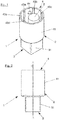
- eine perspektivische Ansicht eines Anschlussadapters zum Anschluss einer Spannvorrichtung an eine Wickelwelle eines Wickelelements, insbesondere einer Plane,
- Fig. 2
- eine Seitenansicht des Anschlussadapters gemäß
Fig. 1 , - Fig. 3
- einen Schnitt entlang einer Linie A-A in
Fig. 2 , - Fig. 4
- eine Draufsicht auf einen ersten Anschlussabschnitt des Anschlussadapters,
- Fig. 5
- eine Draufsicht auf einen zweiten Anschlussabschnitt des Anschlussadapters,
- Fig. 6
- eine vergrößerte Ansicht, die Einzelheiten einer Halterippe innerhalb eines Hohlraums des zweiten Anschlussabschnitts veranschaulicht.
- Ein Anschlussadapter 1 zum Anschluss einer Spannvorrichtung an eine Wickelwelle eines Wickelelements, insbesondere einer Plane eines Lastkraftwagens oder eines Anhängers, umfasst einen Grundkörper 2, der einen ersten Anschlussabschnitt 3 zum Anschluss der Spannvorrichtung, sowie einen zweiten Anschlussabschnitt 4, der dem ersten Anschlussabschnitt 3 gegenüberliegt, zum Anschluss der Wickelwelle des Wickelelements aufweist. Die das Wickelelement bildende Plane kann insbesondere eine seitlich verschiebbare Seitenplane eines Lastkraftwagens oder eines Anhängers sein, um eine Ladefläche des Lastkraftwagens oder Anhängers vor äußeren Einflüssen zu schützen. Die Wickelwelle ist üblicherweise aus einer Aluminiumlegierung hergestellt und weist eine Länge auf, die im Wesentlichen der Höhe des Ladeflächenaufbaus des Lastkraftwagens beziehungsweise Anhängers entspricht. Die Wickelwelle selbst ist rund ausgebildet und weist eine sich von außen nach innen erstreckende runde Ausnehmung mit einem sich in Längsrichtung erstreckenden Längsschlitz auf. Die Ausnehmung und der Längsschlitz erstrecken sich vorzugsweise über die gesamte Länge der Wickelwelle. Die Ausnehmung der Wickelwelle ist so gestaltet, dass die Plane darin eingezogen werden kann. Zu diesem Zweck ist ein Keder vorgesehen, der vorzugsweise einen runden Querschnitt aufweist und an dem ein seitliches Ende der Plane befestigt ist. Der Keder kann insbesondere von dem seitlichen Ende der Plane umnäht sein und ist so ausgebildet, dass er in die runde Ausnehmung der Wickelwelle eingesetzt werden kann und die Plane seitlich aus dem Längsschlitz der Wickelwelle herausgeführt werden kann.
- Die Spannvorrichtung, die zum Beispiel eine Spannratsche, eine Spannkurbel oder dergleichen sein kann, umfasst ein Eingriffselement, welches insbesondere als Außenvierkant mit einem rechteckigen Querschnitt ausgebildet sein kann. Der erste Anschlussabschnitt 3, dessen Einzelheiten insbesondere in
Fig. 4 zu erkennen sind, bildet einen von einer umlaufenden Wandung 31 seitlich begrenzten Hohlraum 30 mit einem rechteckigen, einen Innenvierkant bildenden Querschnitt, so dass das als Außenvierkant ausgebildete Eingriffselement der Spannvorrichtung passend in den ersten Anschlussabschnitt 3 eingesteckt werden kann. Es soll an dieser Stelle angemerkt werden, dass das Eingriffselement der Spannvorrichtung nicht zwingend als Außenvierkant ausgebildet sein muss, sondern auch andere Formgestaltungen aufweisen kann. Die Form des ersten Anschlussabschnitts 3 kann dementsprechend an die Form des Eingriffselements der Spannvorrichtung angepasst werden und zum Beispiel als Innensechskant oder Schlitzaufnahme ausgebildet sein. - Der zweite Anschlussabschnitt 4 des Anschlussadapters 1, der die Verbindung mit der Wickelwelle bereitstellt, umfasst einen Hohlraum 40, der von einer umlaufenden Wandung 41 seitlich begrenzt ist und einen kreisrunden Querschnitt aufweist. Ferner weist der zweite Anschlussabschnitt 4 ein zylindrisch geformtes Eingriffselement 5 auf, das innerhalb des Hohlraums 40 des zweiten Anschlussabschnitts 4 ausgebildet ist. Wie in
Fig. 1 ,3 und 5 zu erkennen, ist das zylindrische Eingriffselement 5, das einen kreisrunden Querschnitt aufweist, exzentrisch innerhalb des Hohlraums 40 des zweiten Anschlussabschnitts 4 angeordnet und somit von der Mitte nach außen in Richtung der Wandung 41 versetzt. Zwischen dem Eingriffselement 5 und einer Innenseite der Wandung 41 ist ein Luftspalt 45 ausgebildet. Das bedeutet, dass das Eingriffselement 5 keinerlei mechanische Verbindung (etwa durch einen Verbindungssteg oder dergleichen) mit der Innenseite der Wandung 41 des Hohlraums 40 des zweiten Anschlussabschnitts 4 aufweist. Insbesondere inFig. 3 ist zu erkennen, dass sich das Eingriffselement 5 von einem Hohlraumgrund 42 des Hohlraums 40 des zweiten Anschlussabschnitts 4 über die gesamte Höhe des Hohlraums 40 erstreckt. - Die Querschnittsform des zweiten Anschlussabschnitts 4, die durch den Querschnitt des Hohlraums 40 und den Querschnitt des darin ausgebildeten exzentrischen Eingriffselements 5 definiert ist, ist so gewählt, dass ein freies Ende der Wickelwelle passend in den Hohlraum 40 eingesetzt werden kann. Wie oben bereits erläutert, weist die Wickelwelle eine sich von außen nach innen erstreckende runde Ausnehmung mit einem Längsschlitz auf. Der Durchmesser des zylindrischen Eingriffselements 5 ist so gewählt, dass das Eingriffselement 5 bei der Montage formschlüssig in die runde Ausnehmung der Wickelwelle eingreifen kann.
- Der Anschlussadapter 1 ist einstückig ausgeführt, so dass das Eingriffselement 5 integral mit dem Grundkörper 2 ausgebildet ist. Um Verformungen des Eingriffselements 5 mit der darauf aufgesteckten Wickelwelle während des (insbesondere horizontalen) Spannens beziehungsweise Entspannens der Plane zu verhindern, ist es zweckmäßig, dass das Eingriffselement 5 aus einem Vollmaterial hergestellt ist.
- Der Anschlussadapter 1 ermöglicht somit einen drehfesten Anschluss der Spannvorrichtung an die Wickelwelle und verbindet diese derart miteinander, dass ein Drehmoment der Spannvorrichtung auf die Wickelwelle übertragen werden kann, so dass die Plane auf- beziehungsweise abgewickelt werden kann.
- Um einen sicheren, drehfesten Halt der Wickelwelle innerhalb des Hohlraums 40 des zweiten Anschlussabschnitts 4 zu erreichen, der insbesondere auch hohen Torsionsbelastungen standhält, kann der Anschlussadapter 1 bei der Montage mit der Wickelwelle, insbesondere hydraulisch, verpresst werden, um dadurch einen wirksamen Form- und Kraftschluss zu erreichen. Um dabei den Kraftschluss zwischen der Wickelwelle und dem Anschlussadapter 1 zu verbessern, weist der zweite Anschlussabschnitt 4 an einer Innenseite der Wandung 41 mehrere, in Umfangsrichtung verteilt angeordnete Halterippen 43a-43e auf, die sich in Längsrichtung über die gesamte Höhe des Hohlraums 40 bis zum Hohlraumgrund 42 des zweiten Anschlussabschnitts 4 erstrecken.
- Der Anschlussadapter 1 und die Wickelwelle, die bei der Herstellung insbesondere hydraulisch miteinander verpresst werden können, können als herstellerseitig vormontierte Einheit in den Verkehr gebracht werden. Der Anschlussadapter 1 kann aber auch als Einzelteil veräußert werden, so dass er vom Kunden mit der zugehörigen Wickelwelle verbunden werden muss. Da nicht jeder Kunde die technischen Möglichkeiten hat, um den Anschlussadapter 1 - vorzugsweise hydraulisch - optimal mit der zugehörigen Wickelwelle zu verpressen, ist in der umlaufenden Wandung 41 des Hohlraums 40 des zweiten Anschlussabschnitts 4 zumindest eine Bohrung 44 ausgebildet, in die ein Sicherungsniet zur Sicherung der Wickelwelle innerhalb des Hohlraums 40 einsetzbar ist. Die Bohrung 44 wurde in
Fig. 5 durch einen Ausbruch veranschaulicht. Mittels des Sicherungsniets wird somit eine zusätzliche Möglichkeit geschaffen, um die Wickelwelle nach dem Einsetzen in den Hohlraum 40 des zweiten Anschlussabschnitts 4 zu sichern. Eine derartige Nietverbindung schafft ebenfalls eine sichere, drehfeste Verbindung der Wickelwelle mit dem zweiten Anschlussabschnitt 4 des Anschlussadapters 1. - Der Anschlussadapter 1 ist vorzugsweise aus einer Aluminiumlegierung hergestellt. Beispielsweise kann es sich bei dieser Legierung um die unter der Bezeichnung EN AW-7075 (Kurzname nach EN: AIZn5,5MgCu) erhältliche, hochfeste Aluminiumlegierung handeln.
- Ein Vorteil der Verwendung einer Aluminiumlegierung zur Herstellung des Anschlussadapters 1 besteht in einer deutlich geringeren Masse im Vergleich zu einem aus Edelstahl hergestellten Anschlussadapter. Die zur Herstellung des Anschlussadapters 1 verwendbaren Aluminiumlegierungen weisen typischerweise eine Dichte im Bereich von etwa 2,8 g/cm3 auf, wohingegen Edelstahl eine Dichte von etwa 8,0 g/cm3 besitzt. Zudem sind Aluminiumlegierungen preisgünstiger als Edelstahl, so dass die Kosten für die Herstellung des Anschlussadapters 1 verringert werden können. Zu dieser Kostenreduktion trägt ebenfalls die Materialersparnis durch den Verzicht auf einen Verbindungssteg zwischen dem Eingriffselement 5 und der Innenseite der Wandung 41 des zweiten Anschlussabschnitts 4 bei.
- Vorzugsweise wird der einstückige Anschlussadapter 1 durch Gesenkschmieden und somit in einem Warmumformungsprozess unter hohem Druck aus der Aluminiumlegierung hergestellt. Das Gesenkschmieden bietet den Vorteil, dass ein sehr homogenes Materialgefüge innerhalb des Anschlussadapters 1 erreicht werden kann. Lunkerbildungen, wie sie häufig bei Gussteilen auftreten, können auf diese Weise ausgeschlossen werden. Dadurch ergibt sich auch bei hohen mechanischen Belastungen, insbesondere Torsionsbelastungen, eine wesentlich geringere Bruchneigung des Anschlussadapters 1.
- Um die mechanischen Eigenschaften, insbesondere die mechanische Festigkeit, weiter zu erhöhen, wird der aus der Aluminiumlegierung hergestellte Anschlussadapter 1 nach dem Gesenkschmieden vorzugsweise einer thermischen Behandlung ausgesetzt und dadurch zusätzlich gehärtet. Insbesondere kann der Anschlussadapter 1 zu diesem Zweck einer so genannten T6-Wärmebehandlung unterzogen werden, die aus folgenden Schritten besteht: Lösungsglühen mit anschließendem Abschrecken und nachfolgendem Warmauslagern zur Ausscheidungshärtung. Es hat sich gezeigt, dass der Anschlussadapter 1 trotz des auf den Warmumformungsprozess folgenden Härtungsprozesses anschließend noch sehr gut mechanisch bearbeitet werden kann. So ist es zum Beispiel möglich, im Nachhinein die mindestens eine Bohrung 44 zur Aufnahme des Sicherungsniets in die umlaufende Wandung 41 des Hohlraums 40 des ersten Anschlussabschnitts 4 einzubringen. Dieses ist bei Anschlussadaptern, die aus Edelstahl hergestellt sind, erheblich schwieriger. Die Verpressung des aus der Aluminiumlegierung hergestellten Anschlussadapters 1 mit der aus einer Aluminiumlegierung hergestellten Wickelwelle (alternativ zur Vernietung) ist ebenfalls leichter möglich.
Claims (11)
- Anschlussadapter (1) zum Anschluss einer Spannvorrichtung an eine Wickelwelle eines Wickelelements, insbesondere einer Plane, umfassend einen Grundkörper (2), der einen ersten Anschlussabschnitt (3), der zum Anschluss an ein Eingriffselement der Spannvorrichtung eingerichtet ist, und einen zweiten Anschlussabschnitt (4), der dem ersten Anschlussabschnitt (3) gegenüberliegt und zum Anschluss an die Wickelwelle eingerichtet ist, aufweist, wobei der zweite Anschlussabschnitt (4) einen von einer umlaufenden Wandung (41) seitlich begrenzten Hohlraum (40) mit einem Hohlraumgrund (42) aufweist, in welchen Hohlraum (40) ein Ende der Wickelwelle einsteckbar ist und innerhalb dessen ein Eingriffselement (5) integral mit dem Grundkörper (2) ausgebildet ist, das so geformt ist, dass es formschlüssig in eine sich von außen nach innen erstreckende, insbesondere einen Längsschlitz umfassende, runde Ausnehmung der Wickelwelle eingreifen kann, wobei das Eingriffselement (5) exzentrisch innerhalb des Hohlraums (40) des zweiten Anschlussabschnitts (4) angeordnet ist und sich vom Hohlraumgrund vorzugsweise im Wesentlichen über die gesamte Höhe des Hohlraums (40) erstreckt, dadurch gekennzeichnet, dass das Eingriffselement (5)- zylinderförmig ausgebildet und- durch einen Luftspalt (45) von der umlaufenden Wandung (41) des Hohlraums (40) beabstandet angeordnet ist.
- Anschlussadapter (1) nach Anspruch 1, dadurch gekennzeichnet, dass an einer Innenseite der Wandung (41) des Hohlraums (40) des zweiten Anschlussabschnitts (4) zumindest eine Halterippe (43a-43e) ausgebildet ist, die sich in Längsrichtung des Hohlraums (40) erstreckt und mit der Wickelwelle verpressbar ist.
- Anschlussadapter (1) nach Anspruch 2, dadurch gekennzeichnet, dass sich die Halterippe (43a-43e) in Längsrichtung über die gesamte Höhe des Hohlraums (40) bis zum Hohlraumgrund (42) des zweiten Anschlussabschnitts (4) erstreckt.
- Anschlussadapter (1) nach einem der Ansprüche 2 oder 3, dadurch gekennzeichnet, dass an einer Innenseite der Wandung (41) des Hohlraums (40) des zweiten Anschlussabschnitts (4) mehrere, in Umfangsrichtung voneinander beabstandete Halterippen (43a-43e) ausgebildet sind, die sich in Längsrichtung des Hohlraums (40) erstrecken und mit der Wickelwelle verpressbar sind.
- Anschlussadapter (1) nach Anspruch 4, dadurch gekennzeichnet, dass sich die Halterippen (43a-43e) in Längsrichtung über die gesamte Höhe des Hohlraums (40) bis zum Hohlraumgrund (42) des zweiten Anschlussabschnitts (4) erstrecken.
- Anschlussadapter (1) nach einem der Ansprüche 1 bis 5, dadurch gekennzeichnet, dass in der Wandung (41) des Hohlraums (40) des zweiten Anschlussabschnitts (4) zumindest eine Bohrung (44) ausgebildet ist, in die ein Sicherungsniet zur Sicherung der Wickelwelle innerhalb des Hohlraums (40) einsetzbar ist.
- Anschlussadapter (1) nach einem der Ansprüche 1 bis 6, dadurch gekennzeichnet, dass der Anschlussadapter (1) aus einer Aluminiumlegierung hergestellt ist.
- Anschlussadapter (1) nach einem der Ansprüche 1 bis 7, dadurch gekennzeichnet, dass der Anschlussadapter (1) durch einen Hochdruck-Warmumformungsprozess hergestellt ist.
- Anschlussadapter (1) nach Anspruch 8, dadurch gekennzeichnet, dass der Anschlussadapter (1) durch Gesenkschmieden hergestellt ist.
- Anschlussadapter (1) nach einem der Ansprüche 1 bis 9, dadurch gekennzeichnet, dass der Anschlussadapter (1) durch thermische Behandlung gehärtet ist.
- Anordnung, umfassend eine Wickelwelle eines Wickelelements, insbesondere einer Plane, und einen Anschlussadapter (1) zum Anschluss einer Spannvorrichtung an die Wickelwelle, wobei der Anschlussadapter (1) mit der Wickelwelle verbunden ist, dadurch gekennzeichnet, dass der Anschlussadapter (1) nach einem der Ansprüche 1 bis 10 ausgeführt ist.
Priority Applications (1)
| Application Number | Priority Date | Filing Date | Title |
|---|---|---|---|
| PL17203058T PL3401140T3 (pl) | 2017-05-08 | 2017-11-22 | Adapter łączący do łączenia urządzenia napinającego do wałka nawojowego elementu nawijanego, w szczególności plandeki |
Applications Claiming Priority (1)
| Application Number | Priority Date | Filing Date | Title |
|---|---|---|---|
| DE202017102727.9U DE202017102727U1 (de) | 2017-05-08 | 2017-05-08 | Anschlussadapter zum Anschluss einer Spannvorrichtung an eine Wickelwelle eines Wickelelements, insbesondere einer Plane |
Publications (2)
| Publication Number | Publication Date |
|---|---|
| EP3401140A1 EP3401140A1 (de) | 2018-11-14 |
| EP3401140B1 true EP3401140B1 (de) | 2019-10-09 |
Family
ID=59119005
Family Applications (1)
| Application Number | Title | Priority Date | Filing Date |
|---|---|---|---|
| EP17203058.7A Active EP3401140B1 (de) | 2017-05-08 | 2017-11-22 | Anschlussadapter zum anschluss einer spannvorrichtung an eine wickelwelle eines wickelelements, insbesondere einer plane |
Country Status (3)
| Country | Link |
|---|---|
| EP (1) | EP3401140B1 (de) |
| DE (1) | DE202017102727U1 (de) |
| PL (1) | PL3401140T3 (de) |
Family Cites Families (4)
| Publication number | Priority date | Publication date | Assignee | Title |
|---|---|---|---|---|
| FR2841615B1 (fr) | 2002-07-01 | 2004-08-20 | Thiriet Fils | Embout pour dispositif d'enroulement d'un element enroulable tel que bache ou similaire, notamment d'un vehicule |
| WO2008142715A1 (en) * | 2007-05-23 | 2008-11-27 | Il Telone S.R.L. | Tensioning device for covers for truckcs |
| KR100861069B1 (ko) * | 2008-04-11 | 2008-09-30 | 주식회사 월드툴 | 래칫 렌치 |
| DE202008012726U1 (de) * | 2008-09-24 | 2008-12-04 | Rs-Kunststoffgesellschaft Mbh | Spannwellenadapter |
-
2017
- 2017-05-08 DE DE202017102727.9U patent/DE202017102727U1/de not_active Expired - Lifetime
- 2017-11-22 PL PL17203058T patent/PL3401140T3/pl unknown
- 2017-11-22 EP EP17203058.7A patent/EP3401140B1/de active Active
Non-Patent Citations (1)
| Title |
|---|
| None * |
Also Published As
| Publication number | Publication date |
|---|---|
| DE202017102727U1 (de) | 2017-06-07 |
| EP3401140A1 (de) | 2018-11-14 |
| PL3401140T3 (pl) | 2020-01-31 |
Similar Documents
| Publication | Publication Date | Title |
|---|---|---|
| DE60312971T2 (de) | Anstauchbares befestigungselement mit optimierten verriegelungsnuten und scheiteln und verfahren zur ausführung desselben | |
| DE19811813A1 (de) | Seitliche Auslegerverriegelung | |
| EP3096963B1 (de) | Bauteilanbindung mit querkraftabstützender stützfläche | |
| EP3199259B1 (de) | Teleskopstütze und Aussenrohr einer Teleskopstützet | |
| DE1400003A1 (de) | Verfahren zum Herstellen einer zugfesten Verbindung zwischen einer Metallarmatur undeinem glatten zylindrischen Stab oder Rohr aus glasfaserverstaerktem synthetischen Werkstoff | |
| WO2014114277A1 (de) | Drahtseilmontageeinheit | |
| EP2844601A1 (de) | Ringschraube mit gleitscheibe | |
| DE10050777B4 (de) | Luftfeder und Verfahren zur Herstellung einer Luftfeder | |
| EP2795019B1 (de) | Gegenseitige, lösbare verbindung zweier stützenabschnitte einer längenveränderlichen baustütze | |
| EP2300723B1 (de) | Spreizhülse und verbindung | |
| EP3401140A1 (de) | Anschlussadapter zum anschluss einer spannvorrichtung an eine wickelwelle eines wickelelements, insbesondere einer plane | |
| EP0091992A2 (de) | Befestigungsvorrichtung für das bandförmige Tragmittel eines Hebezeuges | |
| EP3379091A1 (de) | Befestigungsvorrichtung für ein spannband | |
| DE202009012255U1 (de) | Kraftaufnehmendes Verbindungselement | |
| DE102005034553B4 (de) | Stützwinde | |
| EP3819042A1 (de) | Speisereinsatz mit federndem metallfuss | |
| EP3851616A1 (de) | Transportanker mit halteband | |
| EP2855974B1 (de) | Kettenverkürzungselement mit sicherungsmittel | |
| DE102014221741B4 (de) | Schwenkmodul einer Anhängerkupplung | |
| EP2841795B1 (de) | Kraftübertragungseinheit | |
| DE19802769C1 (de) | Hohlprofil für die Metallverformung mittels eines Magnetfeldes | |
| EP3305568B1 (de) | Ratschenspannvorrichtung sowie adapterteil für eine aufwickelwelle für eine lkw-verkleidung | |
| DE6800415U (de) | Stoesselstange | |
| DE3334250C2 (de) | ||
| DE29909709U1 (de) | Doppelspannelement für Federspanner |
Legal Events
| Date | Code | Title | Description |
|---|---|---|---|
| PUAI | Public reference made under article 153(3) epc to a published international application that has entered the european phase |
Free format text: ORIGINAL CODE: 0009012 |
|
| STAA | Information on the status of an ep patent application or granted ep patent |
Free format text: STATUS: THE APPLICATION HAS BEEN PUBLISHED |
|
| AK | Designated contracting states |
Kind code of ref document: A1 Designated state(s): AL AT BE BG CH CY CZ DE DK EE ES FI FR GB GR HR HU IE IS IT LI LT LU LV MC MK MT NL NO PL PT RO RS SE SI SK SM TR |
|
| AX | Request for extension of the european patent |
Extension state: BA ME |
|
| STAA | Information on the status of an ep patent application or granted ep patent |
Free format text: STATUS: REQUEST FOR EXAMINATION WAS MADE |
|
| 17P | Request for examination filed |
Effective date: 20181210 |
|
| RBV | Designated contracting states (corrected) |
Designated state(s): AL AT BE BG CH CY CZ DE DK EE ES FI FR GB GR HR HU IE IS IT LI LT LU LV MC MK MT NL NO PL PT RO RS SE SI SK SM TR |
|
| GRAP | Despatch of communication of intention to grant a patent |
Free format text: ORIGINAL CODE: EPIDOSNIGR1 |
|
| STAA | Information on the status of an ep patent application or granted ep patent |
Free format text: STATUS: GRANT OF PATENT IS INTENDED |
|
| INTG | Intention to grant announced |
Effective date: 20190415 |
|
| GRAS | Grant fee paid |
Free format text: ORIGINAL CODE: EPIDOSNIGR3 |
|
| GRAA | (expected) grant |
Free format text: ORIGINAL CODE: 0009210 |
|
| STAA | Information on the status of an ep patent application or granted ep patent |
Free format text: STATUS: THE PATENT HAS BEEN GRANTED |
|
| AK | Designated contracting states |
Kind code of ref document: B1 Designated state(s): AL AT BE BG CH CY CZ DE DK EE ES FI FR GB GR HR HU IE IS IT LI LT LU LV MC MK MT NL NO PL PT RO RS SE SI SK SM TR |
|
| REG | Reference to a national code |
Ref country code: GB Ref legal event code: FG4D Free format text: NOT ENGLISH |
|
| REG | Reference to a national code |
Ref country code: CH Ref legal event code: EP |
|
| REG | Reference to a national code |
Ref country code: IE Ref legal event code: FG4D Free format text: LANGUAGE OF EP DOCUMENT: GERMAN |
|
| REG | Reference to a national code |
Ref country code: DE Ref legal event code: R096 Ref document number: 502017002515 Country of ref document: DE Ref country code: CH Ref legal event code: NV Representative=s name: DR.-ING. ULRICH KOETTER, CH |
|
| REG | Reference to a national code |
Ref country code: NL Ref legal event code: FP |
|
| REG | Reference to a national code |
Ref country code: AT Ref legal event code: REF Ref document number: 1188382 Country of ref document: AT Kind code of ref document: T Effective date: 20191115 |
|
| REG | Reference to a national code |
Ref country code: LT Ref legal event code: MG4D |
|
| PG25 | Lapsed in a contracting state [announced via postgrant information from national office to epo] |
Ref country code: ES Free format text: LAPSE BECAUSE OF FAILURE TO SUBMIT A TRANSLATION OF THE DESCRIPTION OR TO PAY THE FEE WITHIN THE PRESCRIBED TIME-LIMIT Effective date: 20191009 Ref country code: PT Free format text: LAPSE BECAUSE OF FAILURE TO SUBMIT A TRANSLATION OF THE DESCRIPTION OR TO PAY THE FEE WITHIN THE PRESCRIBED TIME-LIMIT Effective date: 20200210 Ref country code: SE Free format text: LAPSE BECAUSE OF FAILURE TO SUBMIT A TRANSLATION OF THE DESCRIPTION OR TO PAY THE FEE WITHIN THE PRESCRIBED TIME-LIMIT Effective date: 20191009 Ref country code: LV Free format text: LAPSE BECAUSE OF FAILURE TO SUBMIT A TRANSLATION OF THE DESCRIPTION OR TO PAY THE FEE WITHIN THE PRESCRIBED TIME-LIMIT Effective date: 20191009 Ref country code: GR Free format text: LAPSE BECAUSE OF FAILURE TO SUBMIT A TRANSLATION OF THE DESCRIPTION OR TO PAY THE FEE WITHIN THE PRESCRIBED TIME-LIMIT Effective date: 20200110 Ref country code: BG Free format text: LAPSE BECAUSE OF FAILURE TO SUBMIT A TRANSLATION OF THE DESCRIPTION OR TO PAY THE FEE WITHIN THE PRESCRIBED TIME-LIMIT Effective date: 20200109 Ref country code: FI Free format text: LAPSE BECAUSE OF FAILURE TO SUBMIT A TRANSLATION OF THE DESCRIPTION OR TO PAY THE FEE WITHIN THE PRESCRIBED TIME-LIMIT Effective date: 20191009 Ref country code: NO Free format text: LAPSE BECAUSE OF FAILURE TO SUBMIT A TRANSLATION OF THE DESCRIPTION OR TO PAY THE FEE WITHIN THE PRESCRIBED TIME-LIMIT Effective date: 20200109 Ref country code: LT Free format text: LAPSE BECAUSE OF FAILURE TO SUBMIT A TRANSLATION OF THE DESCRIPTION OR TO PAY THE FEE WITHIN THE PRESCRIBED TIME-LIMIT Effective date: 20191009 |
|
| PG25 | Lapsed in a contracting state [announced via postgrant information from national office to epo] |
Ref country code: RS Free format text: LAPSE BECAUSE OF FAILURE TO SUBMIT A TRANSLATION OF THE DESCRIPTION OR TO PAY THE FEE WITHIN THE PRESCRIBED TIME-LIMIT Effective date: 20191009 Ref country code: HR Free format text: LAPSE BECAUSE OF FAILURE TO SUBMIT A TRANSLATION OF THE DESCRIPTION OR TO PAY THE FEE WITHIN THE PRESCRIBED TIME-LIMIT Effective date: 20191009 Ref country code: IS Free format text: LAPSE BECAUSE OF FAILURE TO SUBMIT A TRANSLATION OF THE DESCRIPTION OR TO PAY THE FEE WITHIN THE PRESCRIBED TIME-LIMIT Effective date: 20200224 |
|
| PG25 | Lapsed in a contracting state [announced via postgrant information from national office to epo] |
Ref country code: AL Free format text: LAPSE BECAUSE OF FAILURE TO SUBMIT A TRANSLATION OF THE DESCRIPTION OR TO PAY THE FEE WITHIN THE PRESCRIBED TIME-LIMIT Effective date: 20191009 |
|
| REG | Reference to a national code |
Ref country code: DE Ref legal event code: R097 Ref document number: 502017002515 Country of ref document: DE |
|
| PG2D | Information on lapse in contracting state deleted |
Ref country code: IS |
|
| PG25 | Lapsed in a contracting state [announced via postgrant information from national office to epo] |
Ref country code: EE Free format text: LAPSE BECAUSE OF FAILURE TO SUBMIT A TRANSLATION OF THE DESCRIPTION OR TO PAY THE FEE WITHIN THE PRESCRIBED TIME-LIMIT Effective date: 20191009 Ref country code: RO Free format text: LAPSE BECAUSE OF FAILURE TO SUBMIT A TRANSLATION OF THE DESCRIPTION OR TO PAY THE FEE WITHIN THE PRESCRIBED TIME-LIMIT Effective date: 20191009 Ref country code: DK Free format text: LAPSE BECAUSE OF FAILURE TO SUBMIT A TRANSLATION OF THE DESCRIPTION OR TO PAY THE FEE WITHIN THE PRESCRIBED TIME-LIMIT Effective date: 20191009 Ref country code: LU Free format text: LAPSE BECAUSE OF NON-PAYMENT OF DUE FEES Effective date: 20191122 Ref country code: MC Free format text: LAPSE BECAUSE OF FAILURE TO SUBMIT A TRANSLATION OF THE DESCRIPTION OR TO PAY THE FEE WITHIN THE PRESCRIBED TIME-LIMIT Effective date: 20191009 Ref country code: IS Free format text: LAPSE BECAUSE OF FAILURE TO SUBMIT A TRANSLATION OF THE DESCRIPTION OR TO PAY THE FEE WITHIN THE PRESCRIBED TIME-LIMIT Effective date: 20200209 |
|
| PLBE | No opposition filed within time limit |
Free format text: ORIGINAL CODE: 0009261 |
|
| STAA | Information on the status of an ep patent application or granted ep patent |
Free format text: STATUS: NO OPPOSITION FILED WITHIN TIME LIMIT |
|
| REG | Reference to a national code |
Ref country code: BE Ref legal event code: MM Effective date: 20191130 |
|
| PG25 | Lapsed in a contracting state [announced via postgrant information from national office to epo] |
Ref country code: SM Free format text: LAPSE BECAUSE OF FAILURE TO SUBMIT A TRANSLATION OF THE DESCRIPTION OR TO PAY THE FEE WITHIN THE PRESCRIBED TIME-LIMIT Effective date: 20191009 Ref country code: SK Free format text: LAPSE BECAUSE OF FAILURE TO SUBMIT A TRANSLATION OF THE DESCRIPTION OR TO PAY THE FEE WITHIN THE PRESCRIBED TIME-LIMIT Effective date: 20191009 |
|
| 26N | No opposition filed |
Effective date: 20200710 |
|
| PG25 | Lapsed in a contracting state [announced via postgrant information from national office to epo] |
Ref country code: IE Free format text: LAPSE BECAUSE OF NON-PAYMENT OF DUE FEES Effective date: 20191122 |
|
| PG25 | Lapsed in a contracting state [announced via postgrant information from national office to epo] |
Ref country code: SI Free format text: LAPSE BECAUSE OF FAILURE TO SUBMIT A TRANSLATION OF THE DESCRIPTION OR TO PAY THE FEE WITHIN THE PRESCRIBED TIME-LIMIT Effective date: 20191009 Ref country code: BE Free format text: LAPSE BECAUSE OF NON-PAYMENT OF DUE FEES Effective date: 20191130 |
|
| PG25 | Lapsed in a contracting state [announced via postgrant information from national office to epo] |
Ref country code: CY Free format text: LAPSE BECAUSE OF FAILURE TO SUBMIT A TRANSLATION OF THE DESCRIPTION OR TO PAY THE FEE WITHIN THE PRESCRIBED TIME-LIMIT Effective date: 20191009 |
|
| PG25 | Lapsed in a contracting state [announced via postgrant information from national office to epo] |
Ref country code: MT Free format text: LAPSE BECAUSE OF FAILURE TO SUBMIT A TRANSLATION OF THE DESCRIPTION OR TO PAY THE FEE WITHIN THE PRESCRIBED TIME-LIMIT Effective date: 20191009 Ref country code: HU Free format text: LAPSE BECAUSE OF FAILURE TO SUBMIT A TRANSLATION OF THE DESCRIPTION OR TO PAY THE FEE WITHIN THE PRESCRIBED TIME-LIMIT; INVALID AB INITIO Effective date: 20171122 |
|
| PG25 | Lapsed in a contracting state [announced via postgrant information from national office to epo] |
Ref country code: TR Free format text: LAPSE BECAUSE OF FAILURE TO SUBMIT A TRANSLATION OF THE DESCRIPTION OR TO PAY THE FEE WITHIN THE PRESCRIBED TIME-LIMIT Effective date: 20191009 |
|
| PG25 | Lapsed in a contracting state [announced via postgrant information from national office to epo] |
Ref country code: MK Free format text: LAPSE BECAUSE OF FAILURE TO SUBMIT A TRANSLATION OF THE DESCRIPTION OR TO PAY THE FEE WITHIN THE PRESCRIBED TIME-LIMIT Effective date: 20191009 |
|
| GBPC | Gb: european patent ceased through non-payment of renewal fee |
Effective date: 20211122 |
|
| PG25 | Lapsed in a contracting state [announced via postgrant information from national office to epo] |
Ref country code: GB Free format text: LAPSE BECAUSE OF NON-PAYMENT OF DUE FEES Effective date: 20211122 |
|
| P01 | Opt-out of the competence of the unified patent court (upc) registered |
Effective date: 20230508 |
|
| PGFP | Annual fee paid to national office [announced via postgrant information from national office to epo] |
Ref country code: NL Payment date: 20231122 Year of fee payment: 7 |
|
| PGFP | Annual fee paid to national office [announced via postgrant information from national office to epo] |
Ref country code: IT Payment date: 20231130 Year of fee payment: 7 Ref country code: FR Payment date: 20231122 Year of fee payment: 7 Ref country code: DE Payment date: 20231113 Year of fee payment: 7 Ref country code: CZ Payment date: 20231110 Year of fee payment: 7 Ref country code: CH Payment date: 20231202 Year of fee payment: 7 Ref country code: AT Payment date: 20231117 Year of fee payment: 7 |
|
| PGFP | Annual fee paid to national office [announced via postgrant information from national office to epo] |
Ref country code: PL Payment date: 20231114 Year of fee payment: 7 |
|
| REG | Reference to a national code |
Ref country code: DE Ref legal event code: R081 Ref document number: 502017002515 Country of ref document: DE Owner name: IMA-FM-1896 GMBH & CO. KG, DE Free format text: FORMER OWNER: FRANZ MIEDERHOFF OHG, 59846 SUNDERN, DE |
|
| REG | Reference to a national code |
Ref country code: NL Ref legal event code: PD Owner name: IMA-FM-1986 GMBH & CO. KG; DE Free format text: DETAILS ASSIGNMENT: CHANGE OF OWNER(S), ASSIGNMENT; FORMER OWNER NAME: FRANZ MIEDERHOFF OHG Effective date: 20240531 |
|
| REG | Reference to a national code |
Ref country code: AT Ref legal event code: PC Ref document number: 1188382 Country of ref document: AT Kind code of ref document: T Owner name: IMA-FM-1896 GMBH & CO. KG, DE Effective date: 20240806 |
|
| REG | Reference to a national code |
Ref country code: DE Ref legal event code: R119 Ref document number: 502017002515 Country of ref document: DE |
|
| REG | Reference to a national code |
Ref country code: CH Ref legal event code: PL |
|
| REG | Reference to a national code |
Ref country code: NL Ref legal event code: MM Effective date: 20241201 |
|
| REG | Reference to a national code |
Ref country code: AT Ref legal event code: MM01 Ref document number: 1188382 Country of ref document: AT Kind code of ref document: T Effective date: 20241122 Ref country code: CH Ref legal event code: PL |
|
| PG25 | Lapsed in a contracting state [announced via postgrant information from national office to epo] |
Ref country code: CH Free format text: LAPSE BECAUSE OF NON-PAYMENT OF DUE FEES Effective date: 20241130 |
|
| PG25 | Lapsed in a contracting state [announced via postgrant information from national office to epo] |
Ref country code: AT Free format text: LAPSE BECAUSE OF NON-PAYMENT OF DUE FEES Effective date: 20241122 |
|
| PG25 | Lapsed in a contracting state [announced via postgrant information from national office to epo] |
Ref country code: CZ Free format text: LAPSE BECAUSE OF NON-PAYMENT OF DUE FEES Effective date: 20241122 |
|
| PG25 | Lapsed in a contracting state [announced via postgrant information from national office to epo] |
Ref country code: NL Free format text: LAPSE BECAUSE OF NON-PAYMENT OF DUE FEES Effective date: 20241201 |
|
| PG25 | Lapsed in a contracting state [announced via postgrant information from national office to epo] |
Ref country code: DE Free format text: LAPSE BECAUSE OF NON-PAYMENT OF DUE FEES Effective date: 20250603 |
|
| PG25 | Lapsed in a contracting state [announced via postgrant information from national office to epo] |
Ref country code: IT Free format text: LAPSE BECAUSE OF NON-PAYMENT OF DUE FEES Effective date: 20241122 |
|
| PG25 | Lapsed in a contracting state [announced via postgrant information from national office to epo] |
Ref country code: FR Free format text: LAPSE BECAUSE OF NON-PAYMENT OF DUE FEES Effective date: 20241130 |