EP3401061A1 - Outil électrique, assemblage d'un tel outil électrique et accessoire - Google Patents
Outil électrique, assemblage d'un tel outil électrique et accessoire Download PDFInfo
- Publication number
- EP3401061A1 EP3401061A1 EP18169042.1A EP18169042A EP3401061A1 EP 3401061 A1 EP3401061 A1 EP 3401061A1 EP 18169042 A EP18169042 A EP 18169042A EP 3401061 A1 EP3401061 A1 EP 3401061A1
- Authority
- EP
- European Patent Office
- Prior art keywords
- accessory
- drive shaft
- type
- drive
- power tool
- Prior art date
- Legal status (The legal status is an assumption and is not a legal conclusion. Google has not performed a legal analysis and makes no representation as to the accuracy of the status listed.)
- Granted
Links
- 230000004888 barrier function Effects 0.000 claims description 9
- 230000005540 biological transmission Effects 0.000 claims description 4
- 238000010276 construction Methods 0.000 claims description 3
- 230000010355 oscillation Effects 0.000 description 2
- 230000003213 activating effect Effects 0.000 description 1
- 230000004913 activation Effects 0.000 description 1
- 230000003247 decreasing effect Effects 0.000 description 1
- 230000001419 dependent effect Effects 0.000 description 1
- 230000002708 enhancing effect Effects 0.000 description 1
Images


Classifications
-
- B—PERFORMING OPERATIONS; TRANSPORTING
- B25—HAND TOOLS; PORTABLE POWER-DRIVEN TOOLS; MANIPULATORS
- B25F—COMBINATION OR MULTI-PURPOSE TOOLS NOT OTHERWISE PROVIDED FOR; DETAILS OR COMPONENTS OF PORTABLE POWER-DRIVEN TOOLS NOT PARTICULARLY RELATED TO THE OPERATIONS PERFORMED AND NOT OTHERWISE PROVIDED FOR
- B25F3/00—Associations of tools for different working operations with one portable power-drive means; Adapters therefor
Definitions
- the present invention relates to a power tool, and to an assembly of a power tool and an accessory.
- Power tools are often designed for one specific type of use. Whereas professional users posses tools dedicated for each purpose, this is often not the case for do-it-yourself (DIY) workers. Many DIY-workers would prefer to have a power tool capable of being adapted for multiple purposes.
- DIY do-it-yourself
- An object of the present invention is to provide a power tool, that is improved relative to the prior art and wherein at least one of the above stated problems is obviated.
- the power tool according to the present invention comprising:
- the drive drives both the first drive shaft and the second drive shaft simultaneously.
- a user may couple a desired type of accessory that is configured to be used for a dedicated purpose. In this way, a power tool is provided that is capable of being adapted for multiple purposes.
- the first drive shaft may be an oscillating drive shaft
- the first type of accessory may be a unit that is configured to drive an oscillating tool.
- the second drive shaft may be a rotating drive shaft
- the second type of accessory may be a unit that is configured to drive a rotating tool, e.g. a circular saw blade.
- the first drive shaft and the second drive shaft extend in the same direction relative to the drive. This allows an accessory that is coupled to one of the first drive shaft or the second drive shaft to shield the other of the first or the second drive shaft.
- said power tool further comprises a trigger that is configured to switch said drive on and off, wherein the trigger comprises:
- a momentary state is a state wherein the power tool is automatically turned “off' when the trigger is released.
- a trigger that comprises a lock-on state is to be interpreted as a trigger that can be locked in an "on"-state.
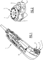
- a power tool 1 comprises a drive 2 and a first drive shaft 3 that is connected to said drive 2, and that has a first engagement 4 that is configured to engage a first type of accessory 5.
- the power tool 1 further comprises a second drive shaft 6 that is connected to said drive 2, and that has a second engagement 7 that is configured to engage a second type of accessory 8.
- the drive 2 is configured to drive the first drive shaft 3 and the second drive shaft 6 simultaneously.
- a user may couple a desired type of accessory 5, 8 that is configured to be used for a dedicated purpose.
- the power tool 1 is capable of being adapted for multiple purposes.
- the first drive shaft 3 is an oscillating drive shaft
- the first type of accessory 5 is a unit 9 that is configured to drive an oscillating tool 10.
- the second drive shaft 6 is a rotating drive shaft
- the second type of accessory 8 is a unit 11 that is configured to drive a rotating tool 17, e.g. a circular saw blade.
- a set of conical gears 13, 14 is used to drive the second drive shaft 6, i.e. the rotating drive shaft.
- the partially exploded Figure 6 shows an eccentric shaft 15 that engages an arm 16 that is fixed to the first drive shaft 3, i.e. the oscillating drive shaft.
- the power tool 1 further comprises a trigger 12 that is configured to switch said drive 2 on and off.
- the trigger 12 comprises a lock-on state or position ( Figure 11C ) in an engaged state of the first type of accessory 5, and a momentary state or position ( Figure 11B ) in an engaged state of the second type of accessory 8.
- the second type of accessory 8 is embodied in the Figures as a rotating tool 17 in the form of a circular saw blade.
- a circular saw blade is a tool with a relatively high risk associated with continued locked-on operation.
- the high risk circular saw blade must be actively held in an "on"-position by the user for activation thereof.
- the power tool 1 is capable of being adapted for multiple purposes, and also provides the comfort of a locked-on operation where appropriate on the one hand, whereas safety is safeguarded for other situations on the other hand.
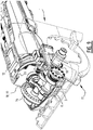
- the unit 11 of the second type of accessory 8 accommodates a rotating tool 17 in the form of a circular saw blade.
- the unit 11 may further comprise a transmission 18 configured to drive said tool 17.
- the transmission 18 may comprise a gear ratio, such that the rotations per minute of said tool 17 are decreased or increased relative to the rotations per minute of the second drive shaft 6.
- the gear ratio may differ between different accessories 8.
- the first type of accessory 5 may also comprise a transmission with a gear ratio, allowing the oscillations per minute to be changed relative to the oscillations per minute of the first drive shaft 3. Again, the gear ratio may differ between different accessories 5.
- the second type of accessory 8 is configured to cover the first drive shaft 3 when it is engaged to the second drive shaft 6 (see Figures 8 and 9 ).
- the first type of accessory 5 may be configured to cover the second drive shaft 6 when it is engaged to the first drive shaft 3, and/or the second drive shaft 6 may be arranged in a countersunk manner, thereby shielding it from exposure.
- the trigger 12 is a sliding trigger
- the second type of accessory 8 activates a barrier 18 that is configured to prevent the sliding trigger 12 from locking in an on-position when said second type of accessory 8 is engaged to the second drive shaft 6 ( Figure 11B ).
- the barrier 18 is movable via said second type of accessory 8 and is pre-tensioned when said second type of accessory 8 is engaged to the second drive shaft 6.
- the pre-tensioning moves the barrier 18 relative to the trigger 12.
- the trigger 12 may now be moved again into a locked-on position ( Figure 11C ).
- the barrier 18 is a moveable element 19, such as a plate 19 that comprises a guide 20 in the form of a chamfer 20.
- Said guide 20 is configured to engage said trigger 12 ( Figures 8-10 and 11B ). If the trigger 12 would accidentally be in a locked-on position when the second type of accessory 8 is brought into engagement with the second drive shaft 6, the guide will force the trigger 12 to an off-position.
- a (not shown) activating member may enable a locked position of the trigger 12, so that - e.g. in an oscillating tool mode - the power tool 1 may be held in an on-state.
- the trigger 12 is connected to an arm 21 with a flange 22 that is configured to engage a micro switch 23.
- the micro switch 23 is connected to a controller 24, which also controls the drive 2.
- the second type of accessory 8 that is associated with the rotating second drive shaft 6 is a high risk tool 17 such as a circular saw blade.
- a grinder may only require a restart protection that guarantees that the power tool is always "off' when the power tool is connected to a power supply, such as a wall socket. This can be obtained using a momentary switch.
- a sander may however be lockable in an "on" position during use.
- Such low risk rotating tools may be provided as a (not shown) third type of accessory that is configured to engage the rotating second drive shaft 6, but will not evoke the momentary state.
- the third type of accessory will not activate a barrier that is configured to prevent the pressure trigger or any part of a trigger construction from locking in an on-state when said third type of accessory is engaged to the second drive shaft.
Priority Applications (1)
| Application Number | Priority Date | Filing Date | Title |
|---|---|---|---|
| EP20207876.2A EP3797930B1 (fr) | 2017-04-25 | 2018-04-24 | Outil électrique |
Applications Claiming Priority (1)
| Application Number | Priority Date | Filing Date | Title |
|---|---|---|---|
| NL2018778A NL2018778B1 (en) | 2017-04-25 | 2017-04-25 | Power tool |
Related Child Applications (2)
| Application Number | Title | Priority Date | Filing Date |
|---|---|---|---|
| EP20207876.2A Division-Into EP3797930B1 (fr) | 2017-04-25 | 2018-04-24 | Outil électrique |
| EP20207876.2A Division EP3797930B1 (fr) | 2017-04-25 | 2018-04-24 | Outil électrique |
Publications (2)
| Publication Number | Publication Date |
|---|---|
| EP3401061A1 true EP3401061A1 (fr) | 2018-11-14 |
| EP3401061B1 EP3401061B1 (fr) | 2020-12-30 |
Family
ID=59521605
Family Applications (2)
| Application Number | Title | Priority Date | Filing Date |
|---|---|---|---|
| EP18169042.1A Active EP3401061B1 (fr) | 2017-04-25 | 2018-04-24 | Outil électrique, assemblage d'un tel outil électrique et accessoire |
| EP20207876.2A Active EP3797930B1 (fr) | 2017-04-25 | 2018-04-24 | Outil électrique |
Family Applications After (1)
| Application Number | Title | Priority Date | Filing Date |
|---|---|---|---|
| EP20207876.2A Active EP3797930B1 (fr) | 2017-04-25 | 2018-04-24 | Outil électrique |
Country Status (2)
| Country | Link |
|---|---|
| EP (2) | EP3401061B1 (fr) |
| NL (1) | NL2018778B1 (fr) |
Citations (4)
| Publication number | Priority date | Publication date | Assignee | Title |
|---|---|---|---|---|
| US4810916A (en) * | 1987-12-16 | 1989-03-07 | Mcbride Scott | Rotary power tool having dual outputs |
| GB2396127A (en) * | 2002-12-14 | 2004-06-16 | Black & Decker Inc | Dual output power tool |
| EP2639015A2 (fr) * | 2012-03-13 | 2013-09-18 | Black & Decker Inc. | Outil électrique |
| DE102012221077A1 (de) * | 2012-11-19 | 2014-05-22 | Robert Bosch Gmbh | Anbaumodul für eine Werkzeugmaschine und Werkzeugmaschine, insbesondere Handwerkzeugmaschine |
Family Cites Families (3)
| Publication number | Priority date | Publication date | Assignee | Title |
|---|---|---|---|---|
| US4818916A (en) | 1987-03-06 | 1989-04-04 | The Perkin-Elmer Corporation | Power system for inductively coupled plasma torch |
| AUPM464594A0 (en) * | 1994-03-23 | 1994-04-21 | Black & Decker Incorporated | Drill configuration |
| US9200713B2 (en) | 2011-12-02 | 2015-12-01 | GM Global Technology Operations LLC | Valve configured for regulating the flow of fluid from a transmission to a cooler |
-
2017
- 2017-04-25 NL NL2018778A patent/NL2018778B1/en active
-
2018
- 2018-04-24 EP EP18169042.1A patent/EP3401061B1/fr active Active
- 2018-04-24 EP EP20207876.2A patent/EP3797930B1/fr active Active
Patent Citations (4)
| Publication number | Priority date | Publication date | Assignee | Title |
|---|---|---|---|---|
| US4810916A (en) * | 1987-12-16 | 1989-03-07 | Mcbride Scott | Rotary power tool having dual outputs |
| GB2396127A (en) * | 2002-12-14 | 2004-06-16 | Black & Decker Inc | Dual output power tool |
| EP2639015A2 (fr) * | 2012-03-13 | 2013-09-18 | Black & Decker Inc. | Outil électrique |
| DE102012221077A1 (de) * | 2012-11-19 | 2014-05-22 | Robert Bosch Gmbh | Anbaumodul für eine Werkzeugmaschine und Werkzeugmaschine, insbesondere Handwerkzeugmaschine |
Also Published As
| Publication number | Publication date |
|---|---|
| NL2018778B1 (en) | 2018-11-05 |
| EP3401061B1 (fr) | 2020-12-30 |
| EP3797930A1 (fr) | 2021-03-31 |
| EP3797930B1 (fr) | 2023-03-29 |
Similar Documents
| Publication | Publication Date | Title |
|---|---|---|
| US9114499B2 (en) | Working tool | |
| US7814818B2 (en) | Modular table saw guarding system riving knife release mechanisms | |
| US6293859B1 (en) | Electric power tool with rotatable handle | |
| US4280026A (en) | Actuator mechanism for a portable, hand-held tool | |
| EP3192620B1 (fr) | Scie à onglet | |
| EP3081335B1 (fr) | Ensemble de protection pour outil électrique | |
| JP2007111853A (ja) | 工具装置のための保護カバー装置 | |
| WO2018043330A1 (fr) | Machine de travail | |
| TW200420375A (en) | Multiple position switch handle with locking mechanism | |
| GB2436438A (en) | Mounting a hood on a portable power tool | |
| EP1518629A1 (fr) | Dispositif de serrage d'un élément d'outil et un mécanisme de pivotement amélioré | |
| US10614977B2 (en) | Hand-held tool machine | |
| US11260502B2 (en) | Hand-held power tool having at least one machine-side contact element | |
| EP3503145B1 (fr) | Système de verrouillage destiné à être utilisé avec un ensemble de déclenchement d'un dispositif électrique | |
| EP3401061B1 (fr) | Outil électrique, assemblage d'un tel outil électrique et accessoire | |
| EP3251791B1 (fr) | Levier réversible pour un ensemble de protection d'un outil électrique | |
| EP2101945A1 (fr) | Machine-outil électrique, telle qu'une meuleuse d'angle, avec un dispositif de blocage de broche | |
| EP3150333B1 (fr) | Outil electrique portatif comprenant un ensemble de freinage amélioré | |
| CN210705394U (zh) | 一种瓷砖切割机的切割机构以及瓷砖切割机 | |
| KR101869334B1 (ko) | 역회전 방지 기구부를 가지는 멀티툴 | |
| JP5398799B2 (ja) | 携帯丸鋸 | |
| AU2017219070B2 (en) | Drive-in device | |
| JP5287068B2 (ja) | 電動工具 | |
| US2322511A (en) | Safety device | |
| KR20160117853A (ko) | 그라인더 휠가드의 고정구조 |
Legal Events
| Date | Code | Title | Description |
|---|---|---|---|
| PUAI | Public reference made under article 153(3) epc to a published international application that has entered the european phase |
Free format text: ORIGINAL CODE: 0009012 |
|
| STAA | Information on the status of an ep patent application or granted ep patent |
Free format text: STATUS: THE APPLICATION HAS BEEN PUBLISHED |
|
| AK | Designated contracting states |
Kind code of ref document: A1 Designated state(s): AL AT BE BG CH CY CZ DE DK EE ES FI FR GB GR HR HU IE IS IT LI LT LU LV MC MK MT NL NO PL PT RO RS SE SI SK SM TR |
|
| AX | Request for extension of the european patent |
Extension state: BA ME |
|
| STAA | Information on the status of an ep patent application or granted ep patent |
Free format text: STATUS: REQUEST FOR EXAMINATION WAS MADE |
|
| 17P | Request for examination filed |
Effective date: 20190514 |
|
| RBV | Designated contracting states (corrected) |
Designated state(s): AL AT BE BG CH CY CZ DE DK EE ES FI FR GB GR HR HU IE IS IT LI LT LU LV MC MK MT NL NO PL PT RO RS SE SI SK SM TR |
|
| GRAP | Despatch of communication of intention to grant a patent |
Free format text: ORIGINAL CODE: EPIDOSNIGR1 |
|
| STAA | Information on the status of an ep patent application or granted ep patent |
Free format text: STATUS: GRANT OF PATENT IS INTENDED |
|
| INTG | Intention to grant announced |
Effective date: 20200729 |
|
| GRAS | Grant fee paid |
Free format text: ORIGINAL CODE: EPIDOSNIGR3 |
|
| GRAA | (expected) grant |
Free format text: ORIGINAL CODE: 0009210 |
|
| STAA | Information on the status of an ep patent application or granted ep patent |
Free format text: STATUS: THE PATENT HAS BEEN GRANTED |
|
| AK | Designated contracting states |
Kind code of ref document: B1 Designated state(s): AL AT BE BG CH CY CZ DE DK EE ES FI FR GB GR HR HU IE IS IT LI LT LU LV MC MK MT NL NO PL PT RO RS SE SI SK SM TR |
|
| REG | Reference to a national code |
Ref country code: GB Ref legal event code: FG4D |
|
| REG | Reference to a national code |
Ref country code: AT Ref legal event code: REF Ref document number: 1349458 Country of ref document: AT Kind code of ref document: T Effective date: 20210115 |
|
| REG | Reference to a national code |
Ref country code: DE Ref legal event code: R096 Ref document number: 602018011222 Country of ref document: DE |
|
| REG | Reference to a national code |
Ref country code: IE Ref legal event code: FG4D |
|
| REG | Reference to a national code |
Ref country code: NL Ref legal event code: FP |
|
| PG25 | Lapsed in a contracting state [announced via postgrant information from national office to epo] |
Ref country code: NO Free format text: LAPSE BECAUSE OF FAILURE TO SUBMIT A TRANSLATION OF THE DESCRIPTION OR TO PAY THE FEE WITHIN THE PRESCRIBED TIME-LIMIT Effective date: 20210330 Ref country code: GR Free format text: LAPSE BECAUSE OF FAILURE TO SUBMIT A TRANSLATION OF THE DESCRIPTION OR TO PAY THE FEE WITHIN THE PRESCRIBED TIME-LIMIT Effective date: 20210331 Ref country code: FI Free format text: LAPSE BECAUSE OF FAILURE TO SUBMIT A TRANSLATION OF THE DESCRIPTION OR TO PAY THE FEE WITHIN THE PRESCRIBED TIME-LIMIT Effective date: 20201230 Ref country code: RS Free format text: LAPSE BECAUSE OF FAILURE TO SUBMIT A TRANSLATION OF THE DESCRIPTION OR TO PAY THE FEE WITHIN THE PRESCRIBED TIME-LIMIT Effective date: 20201230 |
|
| REG | Reference to a national code |
Ref country code: AT Ref legal event code: MK05 Ref document number: 1349458 Country of ref document: AT Kind code of ref document: T Effective date: 20201230 |
|
| PG25 | Lapsed in a contracting state [announced via postgrant information from national office to epo] |
Ref country code: BG Free format text: LAPSE BECAUSE OF FAILURE TO SUBMIT A TRANSLATION OF THE DESCRIPTION OR TO PAY THE FEE WITHIN THE PRESCRIBED TIME-LIMIT Effective date: 20210330 Ref country code: LV Free format text: LAPSE BECAUSE OF FAILURE TO SUBMIT A TRANSLATION OF THE DESCRIPTION OR TO PAY THE FEE WITHIN THE PRESCRIBED TIME-LIMIT Effective date: 20201230 Ref country code: SE Free format text: LAPSE BECAUSE OF FAILURE TO SUBMIT A TRANSLATION OF THE DESCRIPTION OR TO PAY THE FEE WITHIN THE PRESCRIBED TIME-LIMIT Effective date: 20201230 |
|
| PG25 | Lapsed in a contracting state [announced via postgrant information from national office to epo] |
Ref country code: HR Free format text: LAPSE BECAUSE OF FAILURE TO SUBMIT A TRANSLATION OF THE DESCRIPTION OR TO PAY THE FEE WITHIN THE PRESCRIBED TIME-LIMIT Effective date: 20201230 |
|
| REG | Reference to a national code |
Ref country code: LT Ref legal event code: MG9D |
|
| PG25 | Lapsed in a contracting state [announced via postgrant information from national office to epo] |
Ref country code: LT Free format text: LAPSE BECAUSE OF FAILURE TO SUBMIT A TRANSLATION OF THE DESCRIPTION OR TO PAY THE FEE WITHIN THE PRESCRIBED TIME-LIMIT Effective date: 20201230 Ref country code: SK Free format text: LAPSE BECAUSE OF FAILURE TO SUBMIT A TRANSLATION OF THE DESCRIPTION OR TO PAY THE FEE WITHIN THE PRESCRIBED TIME-LIMIT Effective date: 20201230 Ref country code: RO Free format text: LAPSE BECAUSE OF FAILURE TO SUBMIT A TRANSLATION OF THE DESCRIPTION OR TO PAY THE FEE WITHIN THE PRESCRIBED TIME-LIMIT Effective date: 20201230 Ref country code: PT Free format text: LAPSE BECAUSE OF FAILURE TO SUBMIT A TRANSLATION OF THE DESCRIPTION OR TO PAY THE FEE WITHIN THE PRESCRIBED TIME-LIMIT Effective date: 20210430 Ref country code: EE Free format text: LAPSE BECAUSE OF FAILURE TO SUBMIT A TRANSLATION OF THE DESCRIPTION OR TO PAY THE FEE WITHIN THE PRESCRIBED TIME-LIMIT Effective date: 20201230 Ref country code: CZ Free format text: LAPSE BECAUSE OF FAILURE TO SUBMIT A TRANSLATION OF THE DESCRIPTION OR TO PAY THE FEE WITHIN THE PRESCRIBED TIME-LIMIT Effective date: 20201230 |
|
| PG25 | Lapsed in a contracting state [announced via postgrant information from national office to epo] |
Ref country code: AT Free format text: LAPSE BECAUSE OF FAILURE TO SUBMIT A TRANSLATION OF THE DESCRIPTION OR TO PAY THE FEE WITHIN THE PRESCRIBED TIME-LIMIT Effective date: 20201230 Ref country code: PL Free format text: LAPSE BECAUSE OF FAILURE TO SUBMIT A TRANSLATION OF THE DESCRIPTION OR TO PAY THE FEE WITHIN THE PRESCRIBED TIME-LIMIT Effective date: 20201230 |
|
| REG | Reference to a national code |
Ref country code: DE Ref legal event code: R081 Ref document number: 602018011222 Country of ref document: DE Owner name: NANJING CHERVON INDUSTRY CO., LTD., NANJING, CN Free format text: FORMER OWNER: SKIL B.V., BREDA, NL |
|
| PG25 | Lapsed in a contracting state [announced via postgrant information from national office to epo] |
Ref country code: IS Free format text: LAPSE BECAUSE OF FAILURE TO SUBMIT A TRANSLATION OF THE DESCRIPTION OR TO PAY THE FEE WITHIN THE PRESCRIBED TIME-LIMIT Effective date: 20210430 |
|
| REG | Reference to a national code |
Ref country code: DE Ref legal event code: R097 Ref document number: 602018011222 Country of ref document: DE |
|
| REG | Reference to a national code |
Ref country code: NL Ref legal event code: PD Owner name: NANJING CHERVON INDUSTRY CO., LTD.; CN Free format text: DETAILS ASSIGNMENT: CHANGE OF OWNER(S), ASSIGNMENT; FORMER OWNER NAME: SKIL B.V. Effective date: 20210928 Ref country code: GB Ref legal event code: 732E Free format text: REGISTERED BETWEEN 20210930 AND 20211006 |
|
| PG25 | Lapsed in a contracting state [announced via postgrant information from national office to epo] |
Ref country code: IT Free format text: LAPSE BECAUSE OF FAILURE TO SUBMIT A TRANSLATION OF THE DESCRIPTION OR TO PAY THE FEE WITHIN THE PRESCRIBED TIME-LIMIT Effective date: 20201230 Ref country code: AL Free format text: LAPSE BECAUSE OF FAILURE TO SUBMIT A TRANSLATION OF THE DESCRIPTION OR TO PAY THE FEE WITHIN THE PRESCRIBED TIME-LIMIT Effective date: 20201230 |
|
| PLBE | No opposition filed within time limit |
Free format text: ORIGINAL CODE: 0009261 |
|
| STAA | Information on the status of an ep patent application or granted ep patent |
Free format text: STATUS: NO OPPOSITION FILED WITHIN TIME LIMIT |
|
| PG25 | Lapsed in a contracting state [announced via postgrant information from national office to epo] |
Ref country code: MC Free format text: LAPSE BECAUSE OF FAILURE TO SUBMIT A TRANSLATION OF THE DESCRIPTION OR TO PAY THE FEE WITHIN THE PRESCRIBED TIME-LIMIT Effective date: 20201230 Ref country code: DK Free format text: LAPSE BECAUSE OF FAILURE TO SUBMIT A TRANSLATION OF THE DESCRIPTION OR TO PAY THE FEE WITHIN THE PRESCRIBED TIME-LIMIT Effective date: 20201230 |
|
| 26N | No opposition filed |
Effective date: 20211001 |
|
| PG25 | Lapsed in a contracting state [announced via postgrant information from national office to epo] |
Ref country code: LU Free format text: LAPSE BECAUSE OF NON-PAYMENT OF DUE FEES Effective date: 20210424 |
|
| REG | Reference to a national code |
Ref country code: BE Ref legal event code: MM Effective date: 20210430 |
|
| PG25 | Lapsed in a contracting state [announced via postgrant information from national office to epo] |
Ref country code: CH Free format text: LAPSE BECAUSE OF NON-PAYMENT OF DUE FEES Effective date: 20210430 Ref country code: LI Free format text: LAPSE BECAUSE OF NON-PAYMENT OF DUE FEES Effective date: 20210430 Ref country code: ES Free format text: LAPSE BECAUSE OF FAILURE TO SUBMIT A TRANSLATION OF THE DESCRIPTION OR TO PAY THE FEE WITHIN THE PRESCRIBED TIME-LIMIT Effective date: 20201230 |
|
| PG25 | Lapsed in a contracting state [announced via postgrant information from national office to epo] |
Ref country code: SI Free format text: LAPSE BECAUSE OF FAILURE TO SUBMIT A TRANSLATION OF THE DESCRIPTION OR TO PAY THE FEE WITHIN THE PRESCRIBED TIME-LIMIT Effective date: 20201230 |
|
| PG25 | Lapsed in a contracting state [announced via postgrant information from national office to epo] |
Ref country code: IE Free format text: LAPSE BECAUSE OF NON-PAYMENT OF DUE FEES Effective date: 20210424 |
|
| PG25 | Lapsed in a contracting state [announced via postgrant information from national office to epo] |
Ref country code: IS Free format text: LAPSE BECAUSE OF FAILURE TO SUBMIT A TRANSLATION OF THE DESCRIPTION OR TO PAY THE FEE WITHIN THE PRESCRIBED TIME-LIMIT Effective date: 20210430 |
|
| PG25 | Lapsed in a contracting state [announced via postgrant information from national office to epo] |
Ref country code: BE Free format text: LAPSE BECAUSE OF NON-PAYMENT OF DUE FEES Effective date: 20210430 |
|
| PGFP | Annual fee paid to national office [announced via postgrant information from national office to epo] |
Ref country code: FR Payment date: 20230309 Year of fee payment: 6 |
|
| PG25 | Lapsed in a contracting state [announced via postgrant information from national office to epo] |
Ref country code: CY Free format text: LAPSE BECAUSE OF FAILURE TO SUBMIT A TRANSLATION OF THE DESCRIPTION OR TO PAY THE FEE WITHIN THE PRESCRIBED TIME-LIMIT Effective date: 20201230 |
|
| PG25 | Lapsed in a contracting state [announced via postgrant information from national office to epo] |
Ref country code: SM Free format text: LAPSE BECAUSE OF FAILURE TO SUBMIT A TRANSLATION OF THE DESCRIPTION OR TO PAY THE FEE WITHIN THE PRESCRIBED TIME-LIMIT Effective date: 20201230 Ref country code: HU Free format text: LAPSE BECAUSE OF FAILURE TO SUBMIT A TRANSLATION OF THE DESCRIPTION OR TO PAY THE FEE WITHIN THE PRESCRIBED TIME-LIMIT; INVALID AB INITIO Effective date: 20180424 |
|
| PGFP | Annual fee paid to national office [announced via postgrant information from national office to epo] |
Ref country code: DE Payment date: 20230228 Year of fee payment: 6 |
|
| REG | Reference to a national code |
Ref country code: DE Ref legal event code: R082 Ref document number: 602018011222 Country of ref document: DE Representative=s name: SUN, YIMING, M.SC. DIPL. SC. POL. UNIV., DE |
|
| PGFP | Annual fee paid to national office [announced via postgrant information from national office to epo] |
Ref country code: NL Payment date: 20240315 Year of fee payment: 7 |
|
| PG25 | Lapsed in a contracting state [announced via postgrant information from national office to epo] |
Ref country code: MK Free format text: LAPSE BECAUSE OF FAILURE TO SUBMIT A TRANSLATION OF THE DESCRIPTION OR TO PAY THE FEE WITHIN THE PRESCRIBED TIME-LIMIT Effective date: 20201230 |
|
| PGFP | Annual fee paid to national office [announced via postgrant information from national office to epo] |
Ref country code: GB Payment date: 20240307 Year of fee payment: 7 |