EP3797930B1 - Outil électrique - Google Patents
Outil électrique Download PDFInfo
- Publication number
- EP3797930B1 EP3797930B1 EP20207876.2A EP20207876A EP3797930B1 EP 3797930 B1 EP3797930 B1 EP 3797930B1 EP 20207876 A EP20207876 A EP 20207876A EP 3797930 B1 EP3797930 B1 EP 3797930B1
- Authority
- EP
- European Patent Office
- Prior art keywords
- drive shaft
- accessory
- type
- drive
- tool
- Prior art date
- Legal status (The legal status is an assumption and is not a legal conclusion. Google has not performed a legal analysis and makes no representation as to the accuracy of the status listed.)
- Active
Links
- 230000004888 barrier function Effects 0.000 claims description 9
- 230000005540 biological transmission Effects 0.000 claims description 4
- 238000010276 construction Methods 0.000 claims description 3
- 230000010355 oscillation Effects 0.000 description 2
- 230000003213 activating effect Effects 0.000 description 1
- 230000004913 activation Effects 0.000 description 1
- 230000003247 decreasing effect Effects 0.000 description 1
- 230000002708 enhancing effect Effects 0.000 description 1
Images


Classifications
-
- B—PERFORMING OPERATIONS; TRANSPORTING
- B25—HAND TOOLS; PORTABLE POWER-DRIVEN TOOLS; MANIPULATORS
- B25F—COMBINATION OR MULTI-PURPOSE TOOLS NOT OTHERWISE PROVIDED FOR; DETAILS OR COMPONENTS OF PORTABLE POWER-DRIVEN TOOLS NOT PARTICULARLY RELATED TO THE OPERATIONS PERFORMED AND NOT OTHERWISE PROVIDED FOR
- B25F3/00—Associations of tools for different working operations with one portable power-drive means; Adapters therefor
Definitions
- the present invention relates to a power tool, and to an assembly of a power tool.
- Power tools are often designed for one specific type of use. Whereas professional users posses tools dedicated for each purpose, this is often not the case for do-it-yourself (DIX) workers. Many DIX-workers would prefer to have a power tool capable of being adapted for multiple purposes.
- DIX do-it-yourself
- EP 0673723A1 discloses a rotary power tool according to the preamble of claim 1 having two rotary drive heads which are adapted to rotate about spaced generally parallel axes, the drive heads, being relatively positionable so that it is possible to select a respective one of the two drive heads to be located in a forward operational position as desired.
- An object of the present invention is to provide a power tool, that is improved relative to the prior art and wherein at least one of the above stated problems is obviated. Said object is achieved with the invention as defined in the appended set of claims.
- preferred embodiments of the present invention are further elucidated with reference to the drawing, in which:
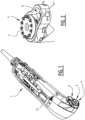
- a power tool 1 comprises a drive 2 and a first drive shaft 3 that is connected to said drive 2, and that has a first engagement 4 that is configured to engage a first type of accessory 5.
- the power tool 1 further comprises a second drive shaft 6 that is connected to said drive 2, and that has a second engagement 7 that is configured to engage a second type of accessory 8.
- the drive 2 is configured to drive the first drive shaft 3 and the second drive shaft 6 simultaneously.
- a user may couple a desired type of accessory 5, 8 that is configured to be used for a dedicated purpose.
- the power tool 1 is capable of being adapted for multiple purposes.
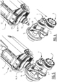
- the first drive shaft 3 is an oscillating drive shaft
- the first type of accessory 5 is a unit 9 that is configured to drive an oscillating tool 10.
- the second drive shaft 6 is a rotating drive shaft
- the second type of accessory 8 is a unit 11 that is configured to drive a rotating tool 17, e.g. a circular saw blade.
- a set of conical gears 13, 14 is used to drive the second drive shaft 6, i.e. the rotating drive shaft.
- the partially exploded Figure 6 shows an eccentric shaft IS that engages an arm 16 that is fixed to the first drive shaft 3, i.e. the oscillating drive shaft.
- the power tool 1 further comprises a trigger 12 that is configured to switch said drive 2 on and off.
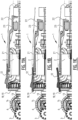
- the trigger 12 comprises a lock-on state or position ( Figure 11C ) in an engaged state of the first type of accessory 5, and a momentary state or position ( Figure 11B ) in an engaged state of the second type of accessory 8.
- the second type of accessory 8 is embodied in the Figures as a rotating tool 17 in the form of a circular saw blade.
- a circular saw blade is a tool with a relatively high risk associated with continued locked-on operation.
- the high risk circular saw blade must be actively held in an "on'-position by the user for activation thereof.
- the power tool 1 is capable of being adapted for multiple purposes, and also provides the comfort of a locked-on operation where appropriate on the one hand, whereas safety is safeguarded for other situations on the other hand.
- the unit 11 of the second type of accessory 8 accommodates a rotating tool 17 in the form of a circular saw blade.
- the unit 11 may further comprise a transmission 18 configured to drive said tool 17.
- the transmission 18 may comprise a gear ratio, such that the rotations per minute of said tool 17 are decreased or increased relative to the rotations per minute of the second drive shaft 6.
- the gear ratio may differ between different accessories 8.
- the fust type of accessory 5 may also comprise a transmission with a gear ratio, allowing the oscillations per minute to be changed relative to the oscillations per minute of the first drive shaft 3. Again, the gear ratio may differ between different accessories 5.
- the second type of accessory 8 is configured to cover the first drive shaft 3 when it is engaged to the second drive shaft 6 (see Figures 8 and 9 ).
- the first type of accessory 5 may be configured to cover the second drive shaft 6 when it is engaged to the first drive shaft 3, and/or the second drive shaft 6 may be arranged in a countersunk manner, thereby shielding it from exposure.
- the trigger 12 is a sliding trigger
- the second type of accessory 8 activates a barrier 18 that is configured to prevent the sliding trigger 12 from locking in an on-position when said second type of accessory 8 is engaged to the second drive shaft 6 ( Figure 11B ).
- the barrier 18 is movable via said second type of accessory 8 and is pre-tensioned when said second type of accessory 8 is engaged to the second drive shaft 6.
- the pre-tensioning moves the barrier 18 relative to the trigger 12.
- the trigger 12 may now be moved again into a locked-on position ( Figure 11C ).
- the barrier 18 is a moveable element 19, such as a plate 19 that comprises a guide 20 in the form of a chamfer 20.
- Said guide 20 is configured to engage said trigger 12 ( Figures 8-10 and 11B ). If the trigger 12 would accidentally be in a locked-on position when the second type of accessory 8 is brought into engagement with the second drive shaft 6, the guide will force the trigger 12 to an off-position.
- a (not shown) activating member may enable a locked position of the trigger 12, so that - e.g. in an oscillating tool mode - the power tool 1 may be held in an on-state.
- the trigger 12 is connected to an arm 21 with a flange 22 that is configured to engage a micro switch 23.
- the micro switch 23 is connected to a controller 24, which also controls the drive 2.
- the second type of accessory 8 that is associated with the rotating second drive shaft 6 is a high risk tool 17 such as a circular saw blade.
- a grinder may only require a restart protection that guarantees that the power tool is always "off" when the power tool is connected to a power supply. such as a wall socket. This can be obtained using a momentary switch.
- a sander may however be lockable in an "on" position during use.
- Such low risk rotating tools may be provided as a (not shown) third type of accessory that is configured to engage the rotating second drive shaft 6, but will not evoke the momentary state. The third type of accessory will not activate a barrier that is configured to prevent the pressure trigger or any part of a trigger construction from locking in an on-state when said third type of accessory is engaged to the second drive shaft.
Landscapes
- Engineering & Computer Science (AREA)
- Mechanical Engineering (AREA)
- Sawing (AREA)
- Portable Power Tools In General (AREA)
Claims (14)
- Outil électrique (1), comprenant :un entraînement (2) ; etun premier arbre d'entraînement (3) qui est relié audit entraînement (2), et ayant un premier engagement (4) qui est configuré pour engager un premier type d'accessoire (5) ;un second arbre d'entraînement (6) qui est relié audit entraînement (2), et ayant un second engagement (7) qui est configuré pour engager un second type d'accessoire (8) ; etdans lequel l'entraînement (2) est configuré pour entraîner le premier arbre d'entraînement (3) et le second arbre d'entraînement (6) simultanément,le premier arbre d'entraînement (3) et le second arbre d'entraînement (6) s'étendent dans la même direction par rapport à l'entraînement (2) ;caractérisé en ce quele premier arbre d'entraînement (3) est un arbre d'entraînement oscillant.
- Outil électrique (1) selon la revendication 1, dans lequel le premier arbre d'entraînement (3) est parallèle au second arbre d'entraînement (6).
- Outil électrique (1) selon l'une quelconque des revendications précédentes, dans lequel le second arbre d'entraînement (6) est un arbre d'entraînement rotatif.
- Outil électrique (1) selon l'une quelconque des revendications précédentes, comprenant en outre un déclencheur (12) qui est configuré pour commuter ledit entraînement (2) en marche et arrêt, dans lequel le déclencheur (12) comprend :un état de verrouillage dans un état engagé du premier type d'accessoire (5) ; etun état momentané dans un état engagé du second type d'accessoire (8).
- Montage d'un outil électrique (1) selon l'une quelconque des revendications 1 - 4 et d'au moins un accessoire (5, 8) qui est configuré pour entraîner un outil (10, 17).
- Montage selon la revendication 5, dans lequel l'accessoire (5, 8) comprend en outre une transmission configurée pour entraîner ledit outil.
- Montage selon la revendication 5 ou 6, dans lequel l'accessoire (5, 8) est du premier type, et dans lequel l'accessoire du premier type (5) est une unité (9) qui est configurée pour entraîner un outil oscillant (10).
- Montage selon la revendication 1 et 7, dans lequel l'outil oscillant (10) peut être couplé directement à l'arbre d'entraînement oscillant (3).
- Montage selon la revendication 7 et 8, dans lequel le premier type d'accessoire (5) est configuré pour couvrir le second arbre d'entraînement (6) lorsqu'il est engagé sur le premier arbre d'entraînement (3).
- Montage selon la revendication 5 ou 6, dans lequel l'accessoire (8) est du second type, et dans lequel le second type d'accessoire (8) est une unité (11) qui est configurée pour entraîner un outil rotatif (17).
- Montage selon la revendication 10, dans lequel le second type d'accessoire (8) est configuré pour couvrir le premier arbre d'entraînement (3) lorsqu'il est engagé sur le second arbre d'entraînement (6).
- Montage selon la revendication 10 ou 11, dans lequel le second type d'accessoire (8) active une barrière (19) qui est configurée pour empêcher le déclencheur (12) ou n'importe quelle partie d'une construction de déclencheur de se verrouiller dans un état de marche lorsque ledit second type d'accessoire (8) est engagé sur le second arbre d'entraînement (6).
- Montage selon la revendication 12, dans lequel la barrière (19) est mobile au moyen du second type d'accessoire (8) et pré-contrainte lorsque ledit second type d'accessoire (8) est engagé sur le second arbre d'entraînement (6).
- Montage selon la revendication 12 ou 13, dans lequel la barrière (19) est un élément mobile qui comprend un guide qui est configuré pour engager le déclencheur ou la construction de déclencheur pour activer l'état momentané.
Applications Claiming Priority (2)
| Application Number | Priority Date | Filing Date | Title |
|---|---|---|---|
| NL2018778A NL2018778B1 (en) | 2017-04-25 | 2017-04-25 | Power tool |
| EP18169042.1A EP3401061B1 (fr) | 2017-04-25 | 2018-04-24 | Outil électrique, assemblage d'un tel outil électrique et accessoire |
Related Parent Applications (2)
| Application Number | Title | Priority Date | Filing Date |
|---|---|---|---|
| EP18169042.1A Division EP3401061B1 (fr) | 2017-04-25 | 2018-04-24 | Outil électrique, assemblage d'un tel outil électrique et accessoire |
| EP18169042.1A Division-Into EP3401061B1 (fr) | 2017-04-25 | 2018-04-24 | Outil électrique, assemblage d'un tel outil électrique et accessoire |
Publications (2)
| Publication Number | Publication Date |
|---|---|
| EP3797930A1 EP3797930A1 (fr) | 2021-03-31 |
| EP3797930B1 true EP3797930B1 (fr) | 2023-03-29 |
Family
ID=59521605
Family Applications (2)
| Application Number | Title | Priority Date | Filing Date |
|---|---|---|---|
| EP18169042.1A Active EP3401061B1 (fr) | 2017-04-25 | 2018-04-24 | Outil électrique, assemblage d'un tel outil électrique et accessoire |
| EP20207876.2A Active EP3797930B1 (fr) | 2017-04-25 | 2018-04-24 | Outil électrique |
Family Applications Before (1)
| Application Number | Title | Priority Date | Filing Date |
|---|---|---|---|
| EP18169042.1A Active EP3401061B1 (fr) | 2017-04-25 | 2018-04-24 | Outil électrique, assemblage d'un tel outil électrique et accessoire |
Country Status (2)
| Country | Link |
|---|---|
| EP (2) | EP3401061B1 (fr) |
| NL (1) | NL2018778B1 (fr) |
Citations (1)
| Publication number | Priority date | Publication date | Assignee | Title |
|---|---|---|---|---|
| EP0673723A1 (fr) * | 1994-03-23 | 1995-09-27 | Black & Decker Inc. | Configuration d'une perceuse |
Family Cites Families (6)
| Publication number | Priority date | Publication date | Assignee | Title |
|---|---|---|---|---|
| US4818916A (en) | 1987-03-06 | 1989-04-04 | The Perkin-Elmer Corporation | Power system for inductively coupled plasma torch |
| US4810916A (en) * | 1987-12-16 | 1989-03-07 | Mcbride Scott | Rotary power tool having dual outputs |
| GB2396127A (en) * | 2002-12-14 | 2004-06-16 | Black & Decker Inc | Dual output power tool |
| US9200713B2 (en) | 2011-12-02 | 2015-12-01 | GM Global Technology Operations LLC | Valve configured for regulating the flow of fluid from a transmission to a cooler |
| CN203236446U (zh) * | 2012-03-13 | 2013-10-16 | 布莱克和戴克公司 | 电动工具 |
| DE102012221077A1 (de) * | 2012-11-19 | 2014-05-22 | Robert Bosch Gmbh | Anbaumodul für eine Werkzeugmaschine und Werkzeugmaschine, insbesondere Handwerkzeugmaschine |
-
2017
- 2017-04-25 NL NL2018778A patent/NL2018778B1/en active
-
2018
- 2018-04-24 EP EP18169042.1A patent/EP3401061B1/fr active Active
- 2018-04-24 EP EP20207876.2A patent/EP3797930B1/fr active Active
Patent Citations (1)
| Publication number | Priority date | Publication date | Assignee | Title |
|---|---|---|---|---|
| EP0673723A1 (fr) * | 1994-03-23 | 1995-09-27 | Black & Decker Inc. | Configuration d'une perceuse |
Also Published As
| Publication number | Publication date |
|---|---|
| EP3401061A1 (fr) | 2018-11-14 |
| EP3401061B1 (fr) | 2020-12-30 |
| NL2018778B1 (en) | 2018-11-05 |
| EP3797930A1 (fr) | 2021-03-31 |
Similar Documents
| Publication | Publication Date | Title |
|---|---|---|
| US9114499B2 (en) | Working tool | |
| EP2420352B1 (fr) | Outils portables | |
| EP3192621B1 (fr) | Scie à onglet | |
| EP1612015A1 (fr) | Outil motorisé | |
| EP1413378A3 (fr) | Poignée à positions multiples avec interrupteur et avec mécanisme de verrouillage | |
| GB2436438A (en) | Mounting a hood on a portable power tool | |
| US11260502B2 (en) | Hand-held power tool having at least one machine-side contact element | |
| EP1518629A1 (fr) | Dispositif de serrage d'un élément d'outil et un mécanisme de pivotement amélioré | |
| US10786893B2 (en) | Switching device for a portable power tool, in particular a hammer drill and/or chisel hammer | |
| EP3251791B1 (fr) | Levier réversible pour un ensemble de protection d'un outil électrique | |
| JP6755913B2 (ja) | 電気装置のトリガーアセンブリーとともに使用するための施錠システム | |
| EP3797930B1 (fr) | Outil électrique | |
| EP2101945B1 (fr) | Machine-outil électrique, telle qu'une meuleuse d'angle, avec un dispositif de blocage de broche | |
| US10456945B2 (en) | Tool for manually operating oscillating motorized tool accessory | |
| GB2433721A (en) | Planing machine with rotary handle having locking means | |
| EP1699601B1 (fr) | Outil electrique a commutation de controle double | |
| AU2017219070B2 (en) | Drive-in device | |
| KR101869334B1 (ko) | 역회전 방지 기구부를 가지는 멀티툴 | |
| KR101625449B1 (ko) | 그라인더 휠가드의 고정구조 | |
| EP2355963B1 (fr) | Machine de coupe combinée munie d'un dispositif de sécurité | |
| US2322511A (en) | Safety device | |
| JP6398518B2 (ja) | 携帯作業機 | |
| AU2022214881A1 (en) | Improvements to power tool apparatus | |
| JPH0464836B2 (fr) | ||
| KR20160117853A (ko) | 그라인더 휠가드의 고정구조 |
Legal Events
| Date | Code | Title | Description |
|---|---|---|---|
| PUAI | Public reference made under article 153(3) epc to a published international application that has entered the european phase |
Free format text: ORIGINAL CODE: 0009012 |
|
| STAA | Information on the status of an ep patent application or granted ep patent |
Free format text: STATUS: THE APPLICATION HAS BEEN PUBLISHED |
|
| AC | Divisional application: reference to earlier application |
Ref document number: 3401061 Country of ref document: EP Kind code of ref document: P |
|
| AK | Designated contracting states |
Kind code of ref document: A1 Designated state(s): AL AT BE BG CH CY CZ DE DK EE ES FI FR GB GR HR HU IE IS IT LI LT LU LV MC MK MT NL NO PL PT RO RS SE SI SK SM TR |
|
| STAA | Information on the status of an ep patent application or granted ep patent |
Free format text: STATUS: REQUEST FOR EXAMINATION WAS MADE |
|
| RIN1 | Information on inventor provided before grant (corrected) |
Inventor name: QUIRIJNEN, ANTONIUS JOHANNES JACOBUS Inventor name: VAN RIJCKEVORSEL, PETRUS PATRICK LEONARDUS |
|
| 17P | Request for examination filed |
Effective date: 20210910 |
|
| RBV | Designated contracting states (corrected) |
Designated state(s): AL AT BE BG CH CY CZ DE DK EE ES FI FR GB GR HR HU IE IS IT LI LT LU LV MC MK MT NL NO PL PT RO RS SE SI SK SM TR |
|
| RAP1 | Party data changed (applicant data changed or rights of an application transferred) |
Owner name: NANJING CHERVON INDUSTRY CO., LTD. |
|
| STAA | Information on the status of an ep patent application or granted ep patent |
Free format text: STATUS: EXAMINATION IS IN PROGRESS |
|
| 17Q | First examination report despatched |
Effective date: 20220121 |
|
| GRAP | Despatch of communication of intention to grant a patent |
Free format text: ORIGINAL CODE: EPIDOSNIGR1 |
|
| STAA | Information on the status of an ep patent application or granted ep patent |
Free format text: STATUS: GRANT OF PATENT IS INTENDED |
|
| INTG | Intention to grant announced |
Effective date: 20230103 |
|
| GRAS | Grant fee paid |
Free format text: ORIGINAL CODE: EPIDOSNIGR3 |
|
| GRAA | (expected) grant |
Free format text: ORIGINAL CODE: 0009210 |
|
| STAA | Information on the status of an ep patent application or granted ep patent |
Free format text: STATUS: THE PATENT HAS BEEN GRANTED |
|
| AC | Divisional application: reference to earlier application |
Ref document number: 3401061 Country of ref document: EP Kind code of ref document: P |
|
| AK | Designated contracting states |
Kind code of ref document: B1 Designated state(s): AL AT BE BG CH CY CZ DE DK EE ES FI FR GB GR HR HU IE IS IT LI LT LU LV MC MK MT NL NO PL PT RO RS SE SI SK SM TR |
|
| REG | Reference to a national code |
Ref country code: CH Ref legal event code: EP |
|
| REG | Reference to a national code |
Ref country code: DE Ref legal event code: R096 Ref document number: 602018047936 Country of ref document: DE |
|
| REG | Reference to a national code |
Ref country code: AT Ref legal event code: REF Ref document number: 1556349 Country of ref document: AT Kind code of ref document: T Effective date: 20230415 |
|
| REG | Reference to a national code |
Ref country code: IE Ref legal event code: FG4D |
|
| REG | Reference to a national code |
Ref country code: LT Ref legal event code: MG9D |
|
| PG25 | Lapsed in a contracting state [announced via postgrant information from national office to epo] |
Ref country code: RS Free format text: LAPSE BECAUSE OF FAILURE TO SUBMIT A TRANSLATION OF THE DESCRIPTION OR TO PAY THE FEE WITHIN THE PRESCRIBED TIME-LIMIT Effective date: 20230329 Ref country code: NO Free format text: LAPSE BECAUSE OF FAILURE TO SUBMIT A TRANSLATION OF THE DESCRIPTION OR TO PAY THE FEE WITHIN THE PRESCRIBED TIME-LIMIT Effective date: 20230629 Ref country code: LV Free format text: LAPSE BECAUSE OF FAILURE TO SUBMIT A TRANSLATION OF THE DESCRIPTION OR TO PAY THE FEE WITHIN THE PRESCRIBED TIME-LIMIT Effective date: 20230329 Ref country code: LT Free format text: LAPSE BECAUSE OF FAILURE TO SUBMIT A TRANSLATION OF THE DESCRIPTION OR TO PAY THE FEE WITHIN THE PRESCRIBED TIME-LIMIT Effective date: 20230329 Ref country code: HR Free format text: LAPSE BECAUSE OF FAILURE TO SUBMIT A TRANSLATION OF THE DESCRIPTION OR TO PAY THE FEE WITHIN THE PRESCRIBED TIME-LIMIT Effective date: 20230329 |
|
| PGFP | Annual fee paid to national office [announced via postgrant information from national office to epo] |
Ref country code: FR Payment date: 20230421 Year of fee payment: 6 Ref country code: DE Payment date: 20230425 Year of fee payment: 6 |
|
| REG | Reference to a national code |
Ref country code: NL Ref legal event code: MP Effective date: 20230329 |
|
| REG | Reference to a national code |
Ref country code: AT Ref legal event code: MK05 Ref document number: 1556349 Country of ref document: AT Kind code of ref document: T Effective date: 20230329 |
|
| PG25 | Lapsed in a contracting state [announced via postgrant information from national office to epo] |
Ref country code: SE Free format text: LAPSE BECAUSE OF FAILURE TO SUBMIT A TRANSLATION OF THE DESCRIPTION OR TO PAY THE FEE WITHIN THE PRESCRIBED TIME-LIMIT Effective date: 20230329 Ref country code: NL Free format text: LAPSE BECAUSE OF FAILURE TO SUBMIT A TRANSLATION OF THE DESCRIPTION OR TO PAY THE FEE WITHIN THE PRESCRIBED TIME-LIMIT Effective date: 20230329 Ref country code: GR Free format text: LAPSE BECAUSE OF FAILURE TO SUBMIT A TRANSLATION OF THE DESCRIPTION OR TO PAY THE FEE WITHIN THE PRESCRIBED TIME-LIMIT Effective date: 20230630 Ref country code: FI Free format text: LAPSE BECAUSE OF FAILURE TO SUBMIT A TRANSLATION OF THE DESCRIPTION OR TO PAY THE FEE WITHIN THE PRESCRIBED TIME-LIMIT Effective date: 20230329 |
|
| PG25 | Lapsed in a contracting state [announced via postgrant information from national office to epo] |
Ref country code: SM Free format text: LAPSE BECAUSE OF FAILURE TO SUBMIT A TRANSLATION OF THE DESCRIPTION OR TO PAY THE FEE WITHIN THE PRESCRIBED TIME-LIMIT Effective date: 20230329 Ref country code: RO Free format text: LAPSE BECAUSE OF FAILURE TO SUBMIT A TRANSLATION OF THE DESCRIPTION OR TO PAY THE FEE WITHIN THE PRESCRIBED TIME-LIMIT Effective date: 20230329 Ref country code: PT Free format text: LAPSE BECAUSE OF FAILURE TO SUBMIT A TRANSLATION OF THE DESCRIPTION OR TO PAY THE FEE WITHIN THE PRESCRIBED TIME-LIMIT Effective date: 20230731 Ref country code: ES Free format text: LAPSE BECAUSE OF FAILURE TO SUBMIT A TRANSLATION OF THE DESCRIPTION OR TO PAY THE FEE WITHIN THE PRESCRIBED TIME-LIMIT Effective date: 20230329 Ref country code: EE Free format text: LAPSE BECAUSE OF FAILURE TO SUBMIT A TRANSLATION OF THE DESCRIPTION OR TO PAY THE FEE WITHIN THE PRESCRIBED TIME-LIMIT Effective date: 20230329 Ref country code: AT Free format text: LAPSE BECAUSE OF FAILURE TO SUBMIT A TRANSLATION OF THE DESCRIPTION OR TO PAY THE FEE WITHIN THE PRESCRIBED TIME-LIMIT Effective date: 20230329 |
|
| PG25 | Lapsed in a contracting state [announced via postgrant information from national office to epo] |
Ref country code: SK Free format text: LAPSE BECAUSE OF FAILURE TO SUBMIT A TRANSLATION OF THE DESCRIPTION OR TO PAY THE FEE WITHIN THE PRESCRIBED TIME-LIMIT Effective date: 20230329 Ref country code: PL Free format text: LAPSE BECAUSE OF FAILURE TO SUBMIT A TRANSLATION OF THE DESCRIPTION OR TO PAY THE FEE WITHIN THE PRESCRIBED TIME-LIMIT Effective date: 20230329 Ref country code: IS Free format text: LAPSE BECAUSE OF FAILURE TO SUBMIT A TRANSLATION OF THE DESCRIPTION OR TO PAY THE FEE WITHIN THE PRESCRIBED TIME-LIMIT Effective date: 20230729 |
|
| REG | Reference to a national code |
Ref country code: CH Ref legal event code: PL |
|
| PG25 | Lapsed in a contracting state [announced via postgrant information from national office to epo] |
Ref country code: LU Free format text: LAPSE BECAUSE OF NON-PAYMENT OF DUE FEES Effective date: 20230424 |
|
| REG | Reference to a national code |
Ref country code: DE Ref legal event code: R097 Ref document number: 602018047936 Country of ref document: DE |
|
| REG | Reference to a national code |
Ref country code: BE Ref legal event code: MM Effective date: 20230430 |
|
| PG25 | Lapsed in a contracting state [announced via postgrant information from national office to epo] |
Ref country code: MC Free format text: LAPSE BECAUSE OF FAILURE TO SUBMIT A TRANSLATION OF THE DESCRIPTION OR TO PAY THE FEE WITHIN THE PRESCRIBED TIME-LIMIT Effective date: 20230329 |
|
| PG25 | Lapsed in a contracting state [announced via postgrant information from national office to epo] |
Ref country code: MC Free format text: LAPSE BECAUSE OF FAILURE TO SUBMIT A TRANSLATION OF THE DESCRIPTION OR TO PAY THE FEE WITHIN THE PRESCRIBED TIME-LIMIT Effective date: 20230329 Ref country code: LI Free format text: LAPSE BECAUSE OF NON-PAYMENT OF DUE FEES Effective date: 20230430 Ref country code: DK Free format text: LAPSE BECAUSE OF FAILURE TO SUBMIT A TRANSLATION OF THE DESCRIPTION OR TO PAY THE FEE WITHIN THE PRESCRIBED TIME-LIMIT Effective date: 20230329 Ref country code: CZ Free format text: LAPSE BECAUSE OF FAILURE TO SUBMIT A TRANSLATION OF THE DESCRIPTION OR TO PAY THE FEE WITHIN THE PRESCRIBED TIME-LIMIT Effective date: 20230329 Ref country code: CH Free format text: LAPSE BECAUSE OF NON-PAYMENT OF DUE FEES Effective date: 20230430 |
|
| PLBE | No opposition filed within time limit |
Free format text: ORIGINAL CODE: 0009261 |
|
| STAA | Information on the status of an ep patent application or granted ep patent |
Free format text: STATUS: NO OPPOSITION FILED WITHIN TIME LIMIT |
|
| REG | Reference to a national code |
Ref country code: IE Ref legal event code: MM4A |
|
| PG25 | Lapsed in a contracting state [announced via postgrant information from national office to epo] |
Ref country code: BE Free format text: LAPSE BECAUSE OF NON-PAYMENT OF DUE FEES Effective date: 20230430 |
|
| 26N | No opposition filed |
Effective date: 20240103 |
|
| PG25 | Lapsed in a contracting state [announced via postgrant information from national office to epo] |
Ref country code: IE Free format text: LAPSE BECAUSE OF NON-PAYMENT OF DUE FEES Effective date: 20230424 |
|
| PG25 | Lapsed in a contracting state [announced via postgrant information from national office to epo] |
Ref country code: IE Free format text: LAPSE BECAUSE OF NON-PAYMENT OF DUE FEES Effective date: 20230424 |
|
| PGFP | Annual fee paid to national office [announced via postgrant information from national office to epo] |
Ref country code: GB Payment date: 20240307 Year of fee payment: 7 |
|
| PG25 | Lapsed in a contracting state [announced via postgrant information from national office to epo] |
Ref country code: SI Free format text: LAPSE BECAUSE OF FAILURE TO SUBMIT A TRANSLATION OF THE DESCRIPTION OR TO PAY THE FEE WITHIN THE PRESCRIBED TIME-LIMIT Effective date: 20230329 |