EP3401020A1 - Material pressure controller - Google Patents
Material pressure controller Download PDFInfo
- Publication number
- EP3401020A1 EP3401020A1 EP18171582.2A EP18171582A EP3401020A1 EP 3401020 A1 EP3401020 A1 EP 3401020A1 EP 18171582 A EP18171582 A EP 18171582A EP 3401020 A1 EP3401020 A1 EP 3401020A1
- Authority
- EP
- European Patent Office
- Prior art keywords
- pressure
- pressure chamber
- wall
- regulator according
- piston
- Prior art date
- Legal status (The legal status is an assumption and is not a legal conclusion. Google has not performed a legal analysis and makes no representation as to the accuracy of the status listed.)
- Granted
Links
Images
Classifications
-
- B—PERFORMING OPERATIONS; TRANSPORTING
- B05—SPRAYING OR ATOMISING IN GENERAL; APPLYING FLUENT MATERIALS TO SURFACES, IN GENERAL
- B05B—SPRAYING APPARATUS; ATOMISING APPARATUS; NOZZLES
- B05B12/00—Arrangements for controlling delivery; Arrangements for controlling the spray area
- B05B12/08—Arrangements for controlling delivery; Arrangements for controlling the spray area responsive to condition of liquid or other fluent material to be discharged, of ambient medium or of target ; responsive to condition of spray devices or of supply means, e.g. pipes, pumps or their drive means
- B05B12/085—Arrangements for controlling delivery; Arrangements for controlling the spray area responsive to condition of liquid or other fluent material to be discharged, of ambient medium or of target ; responsive to condition of spray devices or of supply means, e.g. pipes, pumps or their drive means responsive to flow or pressure of liquid or other fluent material to be discharged
- B05B12/087—Flow or presssure regulators, i.e. non-electric unitary devices comprising a sensing element, e.g. a piston or a membrane, and a controlling element, e.g. a valve
- B05B12/088—Flow or presssure regulators, i.e. non-electric unitary devices comprising a sensing element, e.g. a piston or a membrane, and a controlling element, e.g. a valve the sensing element being a flexible member, e.g. membrane, diaphragm, bellows
-
- G—PHYSICS
- G05—CONTROLLING; REGULATING
- G05D—SYSTEMS FOR CONTROLLING OR REGULATING NON-ELECTRIC VARIABLES
- G05D16/00—Control of fluid pressure
- G05D16/024—Controlling the inlet pressure, e.g. back-pressure regulator
-
- G—PHYSICS
- G05—CONTROLLING; REGULATING
- G05D—SYSTEMS FOR CONTROLLING OR REGULATING NON-ELECTRIC VARIABLES
- G05D16/00—Control of fluid pressure
- G05D16/14—Control of fluid pressure with auxiliary non-electric power
- G05D16/18—Control of fluid pressure with auxiliary non-electric power derived from an external source
- G05D16/185—Control of fluid pressure with auxiliary non-electric power derived from an external source using membranes within the main valve
Definitions
- the invention relates to a material pressure regulator, in particular counter-pressure regulator, according to the preamble of claim 1.
- Coating with the medium is typically done by means of spraying by means of spray nozzles.
- the medium such as a paint
- a pressure circuit fed from a reservoir is usually set up. In this pressure circuit, the medium can be pumped under pressure to be optionally delivered via the spray nozzles.
- Fluid pressure regulators can be used to maintain or maintain pressure in the system. This is in particular a predetermined or adjustable pressure.
- the material pressure regulator has for this purpose a pressure chamber whose volume or cross section is variable. So the pressure at the entrance of the pressure chamber can be adjusted. This is achieved by means of a backpressure for the pressure of the medium, which is adjusted by exposure to a pressure medium, such as usually compressed air.
- This pressure medium represents a back pressure to the pressure of the medium.
- the cross section of the pressure chamber can be adjusted via movable wall sections as a function of the pressure ratio. If the pressure of the medium at the inlet of the circuit drops in relation to the counter-pressure, the cross section of the pressure chamber is reduced so that the pressure rises again. So it can be kept constant.
- a valve device which contains a switching rocker 13 designed as a switching element. At the both sides of the pivoting portion 15 of the rocker switch 13 lying rocker arms 18, 18 'engages in each case an actuating diaphragm 35, 35'. Depending on the position of the rocker switch 13, the pressure in a consumer A is either increased or decreased. Neither rocker switch 13 nor the actuating membranes 35, 35 ', however, form a pressure chamber. Rocker 13 and actuating membranes 35, 35 'are used only to close or release the mouth of a respective associated fluid channel.
- the arrangement is therefore suitable only for the realization of a valve with the two switching states OPEN and CLOSED, but not for the realization of a pressure regulator.
- a disadvantage of the known material pressure regulators is that the pressure chamber has a complicated passage for the medium for maintaining the pressure. Thus, the medium is exposed to strong shear stresses, which has a negative impact on the quality of the medium, especially for fluids such as paints. In addition, in the known solutions cross-sectional changes in normal operation lead to further asymmetries of the flow and thus to additional shear stresses of the medium.
- a material pressure regulator with the features of claim 1 solves this problem.
- the material pressure regulator serves to regulate the pressure of a fluid or fluid medium.
- the medium may in particular be liquids and / or gases.
- these are in particular paints or coatings, ie preferably mixtures, such as emulsions of a liquid with solid particles.
- the pressure of the medium should be kept constant, in particular with respect to a reference pressure.
- a pressure chamber which can be flowed through by an inlet to an outlet from the medium, is provided, wherein the cross section of the pressure chamber is variable for adjusting the pressure at the inlet of the pressure chamber by means of a counter-pressure over the wall of the pressure chamber.
- the material pressure regulator is characterized in that the wall of the pressure chamber is formed of a plurality of movable sections.
- the wall is formed of a plurality, preferably two, independently movable and / or oppositely arranged wall sections. This can be achieved that the pressure chamber is optimally adjustable.
- the flexible wall is designed in particular as at least one membrane.
- it is designed as a membrane with a plurality of membrane sections or is composed of several membranes. This can be provided on the one hand a one-piece, preferably one-piece membrane.
- the wall can be composed of several membrane sections.
- the wall is associated in particular at least one piston.
- each individual wall sections is associated with a piston.
- the wall or the respective wall section is particularly preferably designed to be movable and / or supportable by means of the respective piston.
- the wall sections and / or pistons are arranged symmetrically to the pressure chamber. This allows a symmetrical construction of the pressure chamber.
- the pressure chamber is thus designed for optimized material flow.
- the wall sections are formed in particular of flexible material, wherein the pressure chamber is preferably completely surrounded by flexible material.
- a flexible material is achieved that the wall is movable to adjust the volume of the pressure chamber.
- the piston thus serves as a booster piston, ie for passing a higher pressure than the pressure medium to the medium in the pressure chamber. Due to the different surfaces of the booster piston, an increased back pressure can be built up. The larger area to the pressure medium provides increased pressure on the smaller area toward the pressure chamber.
- two oppositely disposed wall sections form the flexible wall of the valve chamber.
- the membranes are preferably on the edge flat on each other to form the central Pressure chamber.
- the pressure chamber can be easily assembled from two membranes.
- At least one further outer pressure membrane is provided in particular for the spatial separation between the pressure medium and the piston.
- a pressure membrane per piston or a pressure membrane section per piston is used for this purpose.
- the pressure can thus act as back pressure on the piston, without causing losses.
- the pressure chamber preferably has an at least substantially linear and / or symmetrical flow area. At least in the area between the inlet and outlet of the pressure chamber is the case.
- a plurality of independently movable and / or oppositely movable wall sections or membrane sections cooperate to form the pressure chamber.
- an optimal adjustability of the pressure chamber can be achieved.
- the wall sections and / or membranes of the pressure chamber are in particular arranged opposite each other.
- the wall sections and / or membranes and / or pistons are arranged to operate in opposite directions. Opposing membranes or pistons serve to optimally adjust the pressure chamber.
- the back pressure is generated by means of an elastic fluid.
- a gas and / or a liquid is used for this purpose.
- the fluid preferably acts on the piston.
- This solution specifically includes the use of compressed air.
- the back pressure can also be produced or adjusted by means of an elastic solid.
- an elastic solid for this purpose, in particular serve at least one spring or other compressible solid, such as rubber or the like.
- the back pressure is preferably adjustable by bias and / or adjustment of the spring constant of the elastic solid.
- the solid, so in particular, the spring, preferably acts on the piston. This creates the back pressure.
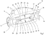
- Fig. 1 a section through a material pressure regulator according to the invention.
- a sectional view of a material pressure regulator 10 according to the invention is shown.
- Its housing 11 contains a pressure chamber 12 in the interior.
- An inlet 13 and an outlet 14 serve to supply or discharge a flowable or fluid medium which can be transported through the pressure chamber 12.
- the medium itself is not shown here.
- the housing 11 is limited in the drawing above and below by a respective lid 15 and 16. These covers 15 and 16 are screwed by means of screws 17 with the rest of the housing 11. Thus, the sealing of the housing 11 can be ensured with respect to the environment.
- the pressure chamber 12 is bounded by two membranes 18 and 19. These membranes 18 and 19 are partially adjacent to each other, namely apart from the region of the inlet 13 and outlet 14 substantially edge side. In the center of the pressure chamber 12, a substantially tubular region for the passage of the medium is formed. This extends from the inlet 13 to the outlet 14. Thus, an almost linear passage through the pressure chamber 12 can take place.
- the two membranes 18 and 19 are contacted by pistons 20 and 21, respectively.
- the pistons 20 and 21 serve to build up a counter-pressure to the pressure of the medium in the interior of the pressure chamber 12.
- the pistons are movably mounted, namely in the direction of the double arrows entered in the drawing for the respective direction of movement 22 or 23 of the pistons 20 and 21. This ensures that the distance of the membranes 18 and 19 and thus the volume of the pressure chamber 12 can be varied , When the pistons 18 and 19 move apart, the volume of the Pressure chamber 12 larger. When the pistons 18 and 19 move toward each other, the volume of the pressure chamber 12 becomes correspondingly smaller.
- the pistons 20 and 21 are each provided with a further pressure membrane 24 or 25.
- the pressure membranes 24 and 25 respectively delimit a pressure chamber 26 and 27 with respect to the respective cover 15 and 16, respectively.
- This pressure chamber 26 and 27 serve to act upon a pressure medium, not shown here, in particular compressed air.
- a back pressure on the piston 20 and 21 are constructed, which acts against the pressure of the medium in the pressure chamber 12.
- Circumferentially surrounding these pressure membranes 24 and 25 are clamped to the housing 11.
- the clamping takes place between the respective cover 15 or 16 and the actual housing 11.
- the membranes 18 and 19 are here also laterally circumferentially clamped on the housing 11.
- the clamping takes place between a membrane holding element 28 or 29, for example in the form of a circular clamping ring, and the actual housing 11.
- the membranes 18, 19, 24, 25 are each held securely and sealingly.
- the piston 20 is surrounded by the membrane 18 and the pressure membrane 24 as a whole.
- the piston 21 with the membrane 19 and the pressure membrane 25.
- This ensures that on the one hand a sealing of the pressure chamber 12 takes place against leakage of the medium.
- the pressure membrane 24 or 25 but also ensures that the print medium can not escape unintentionally.
- the material pressure regulator 10 When used according to the invention, for example in a paint spraying system not shown in detail here, the material pressure regulator 10 is provided, on the one hand, with a supply line of a medium under pressure, in particular a paint or a lacquer. The medium is pumped from a reservoir in the direction of the material pressure regulator 10.
- This supply line can then be fastened to the inlet 13, for example by means of a flange 30.
- the outlet 14 of the material pressure regulator 10 can then be connected in accordance with, for example, by means of a flange 31 with a return for the return of the medium.
- a return conveys the medium not discharged from the nozzles back towards a reservoir. This is how a cycle is formed.
- the material pressure regulator 10 also controls accordingly.
- the pressure in the pressure chamber 12 increases, so that the pistons 20 and 12 are moved against the back pressure to the outside.
- the pressure in the pressure chamber 12 decreases accordingly.
- the pressure chambers 26 and 27 for the two pistons 20 and 21 are typically subjected to the same pressure. This is typically done by a compressed air supply.
- spring action may be provided.
- mechanical springs in particular prestressed springs (compression or tension springs) be used.
- An adjustability of the spring tension for example, the spring travel, ensures adjustability of the back pressure.
- the pressure can be set externally so that optimum pressure conditions are always established, irrespective of the demand from the nozzles of the spray guns or other consumers for the medium.
- the two pistons 20 and 21 and the associated membranes 18, 19, 24, 25 are identical or at least very similar, there is a uniform, in particular symmetrical adjustment to the respective compensation of the back pressure.
- the pressure chamber 12 is enlarged in a symmetrical manner or reduced again.
Abstract
Die Erfindung betrifft einen Materialdruckregler, vorzugsweise einen Gegendruckregler, zur Regelung des Drucks eines fließfähigen Mediums, insbesondere einer Flüssigkeit und/oder eines Gases, mit einer von einem Einlass (13) zu einem Auslass (14) vom Medium durchströmbaren Druckkammer (12). Der Querschnitt der Druckkammer (12) ist variabel zur Einstellung des Drucks am Einlass (13) der Druckkammer (12) mittels eines Gegendrucks über die Wandung der Druckkammer (12). Der Materialdruckregler zeichnet sich dadurch aus, dass die Wandung der Druckkammer (12) aus mehreren beweglichen Abschnitten gebildet ist.

Description
Die Erfindung betrifft einen Materialdruckregler, insbesondere Gegendruckregler, gemäß dem Oberbegriff des Anspruchs 1.The invention relates to a material pressure regulator, in particular counter-pressure regulator, according to the preamble of claim 1.
Ein Verteilen fließfähiger beziehungsweise fluider Medien, wie Flüssigkeiten oder Gasen, erfolgt in einer Vielzahl unterschiedlicher Anwendungen. Dabei sind diese Medien entweder selber das auszubringende Material oder dienen zum Transport eines solchen, beispielsweise als Emulsion. Beispielsweise kann durch Versprühen eine Farbe oder ein Lack auf ein zu beschichtendes Werkstück aufgebracht werden.Distributing flowable or fluid media, such as liquids or gases, takes place in a variety of different applications. These media are either themselves the auszubringende material or serve to transport such, for example as an emulsion. For example, by spraying a paint or a paint can be applied to a workpiece to be coated.
Ein Beschichten mit dem Medium, wie beispielsweise einer Farbe, erfolgt typischerweise mittels durch Versprühen mittels Spritzdüsen. Zur Zuführung des Mediums zur Spritzdüse als Abnehmer sind üblicherweise unter einem Druck stehende Leitungen vorgesehen, die die jeweilige Spritzdüsen mit dem Medium versorgen. Um eine sichere Zuführung zu ermöglichen, wird in der Regel ein aus einem Reservoir gespeister Druckkreislauf eingerichtet. In diesem Druckkreislauf kann das Medium unter Druck umgepumpt werden, um gegebenenfalls über die Spritzdüsen abgegeben zu werden.Coating with the medium, such as a paint, is typically done by means of spraying by means of spray nozzles. For supplying the medium to the spray nozzle as a customer usually under pressure lines are provided which supply the respective spray nozzles with the medium. In order to enable a reliable supply, a pressure circuit fed from a reservoir is usually set up. In this pressure circuit, the medium can be pumped under pressure to be optionally delivered via the spray nozzles.
Sobald allerdings durch einen oder mehrere der Abnehmer, also konkret eine oder mehrere Spritzdüsen, ein Teil des Mediums aus dem Kreislauf entnommen wird, sinkt der Druck des Mediums darin ab. Damit sinkt insbesondere aber auch die Austrittsgeschwindigkeit aus der Düse beziehungsweise den Düsen, so dass sich die Verteilungscharakteristik in unerwünschter Weise ändert.However, as soon as one or more of the consumers, ie in practice one or more spray nozzles, removes part of the medium from the circulation, the pressure of the medium in it decreases. In particular, however, that also decreases Exit velocity from the nozzle or the nozzle, so that the distribution characteristic changes in an undesirable manner.
Materialdruckregler können gerade dazu dienen, den Druck im System aufrechtzuerhalten beziehungsweise konstant zu halten. Dabei handelt es sich insbesondere um einen vorgegebenen oder auch einstellbaren Druck. Der Materialdruckregler weist dazu eine Druckkammer auf, deren Volumen beziehungsweise Querschnitt variabel ist. So kann der Druck am Eingang der Druckkammer eingestellt werden. Dies wird mittels eines Gegendrucks zum Druck des Mediums erreicht, der durch Beaufschlagung mit einem Druckmedium, wie üblicherweise Pressluft, eingestellt wird.Fluid pressure regulators can be used to maintain or maintain pressure in the system. This is in particular a predetermined or adjustable pressure. The material pressure regulator has for this purpose a pressure chamber whose volume or cross section is variable. So the pressure at the entrance of the pressure chamber can be adjusted. This is achieved by means of a backpressure for the pressure of the medium, which is adjusted by exposure to a pressure medium, such as usually compressed air.
Dieses Druckmedium stellt einen Gegendruck zum Druck des Mediums dar. Hierdurch lässt sich der Querschnitt der Druckkammer über bewegliche Wandabschnitte in Abhängigkeit vom Druckverhältnis einstellen. Sinkt der Druck des Mediums am Eingang des Kreislaufs gegenüber dem Gegendruck, wird der Querschnitt der Druckkammer reduziert, so dass der Druck wieder ansteigt. So kann er konstant gehalten werden.This pressure medium represents a back pressure to the pressure of the medium. In this way, the cross section of the pressure chamber can be adjusted via movable wall sections as a function of the pressure ratio. If the pressure of the medium at the inlet of the circuit drops in relation to the counter-pressure, the cross section of the pressure chamber is reduced so that the pressure rises again. So it can be kept constant.
Aus
Nachteilig an der in
Aus
Die Anordnung eignet sich daher lediglich zur Realisierung eines Ventils mit den beiden Schaltzuständen OFFEN und GESCHLOSSEN, nicht aber zur Realisierung eines Druckreglers.The arrangement is therefore suitable only for the realization of a valve with the two switching states OPEN and CLOSED, but not for the realization of a pressure regulator.
Nachteilig an den bekannten Materialdruckreglern ist, dass die Druckkammer einen komplizierten Durchleitungsweg für das Medium zur Aufrechterhaltung der Drucks aufweist. Damit wird das Medium starken Scherbeanspruchungen ausgesetzt, was sich insbesondere bei Fluiden wie Lacken negativ auf die Qualität des Mediums auswirkt. Darüber hinaus führen bei den bekannten Lösungen Querschnittsänderungen im Regelbetrieb zu weiteren Asymmetrien der Strömung und damit zu zusätzlichen Scherbeanspruchungen des Mediums.A disadvantage of the known material pressure regulators is that the pressure chamber has a complicated passage for the medium for maintaining the pressure. Thus, the medium is exposed to strong shear stresses, which has a negative impact on the quality of the medium, especially for fluids such as paints. In addition, in the known solutions cross-sectional changes in normal operation lead to further asymmetries of the flow and thus to additional shear stresses of the medium.
Es ist eine der Erfindung zugrundeliegende Aufgabe, diese Nachteile zu überwinden. Insbesondere soll der Durchleitungsweg durch den Materialdruckregler vereinfacht werden.It is an object underlying the invention to overcome these disadvantages. In particular, the passage should be simplified by the material pressure regulator.
Ein Materialdruckregler mit den Merkmalen des Anspruchs 1 löst diese Aufgabe. Der Materialdruckregler dient dabei zur Regelung des Drucks eines fließfähigen beziehungsweise fluiden Mediums. Bei dem Medium kann es sich insbesondere um Flüssigkeiten und/oder Gase handeln. Beispielsweise bei Spritzanlagen handelt es sich dabei insbesondere um Farben oder Lacke, also vorzugsweise Mischungen, wie Emulsionen einer Flüssigkeit mit Feststoffpartikeln. Vorzugsweise soll der Druck des Mediums konstant gehalten werden, insbesondere gegenüber einem Referenzdruck. Dazu ist eine von einem Einlass zu einem Auslass vom Medium durchströmbare Druckkammer vorgesehen, wobei der Querschnitt der Druckkammer variabel ist zur Einstellung des Drucks am Einlass der Druckkammer mittels eines Gegendrucks über die Wandung der Druckkammer. Der Materialdruckregler zeichnet sich dadurch aus, dass die Wandung der Druckkammer aus mehreren beweglichen Abschnitten gebildet ist. Damit kann die Druckkammer erfindungsgemäß im Hinblick auf eine verbesserte Durchleitung des Mediums optimiert werden.A material pressure regulator with the features of claim 1 solves this problem. The material pressure regulator serves to regulate the pressure of a fluid or fluid medium. The medium may in particular be liquids and / or gases. For example, in the case of spray systems, these are in particular paints or coatings, ie preferably mixtures, such as emulsions of a liquid with solid particles. Preferably, the pressure of the medium should be kept constant, in particular with respect to a reference pressure. For this purpose, a pressure chamber, which can be flowed through by an inlet to an outlet from the medium, is provided, wherein the cross section of the pressure chamber is variable for adjusting the pressure at the inlet of the pressure chamber by means of a counter-pressure over the wall of the pressure chamber. The material pressure regulator is characterized in that the wall of the pressure chamber is formed of a plurality of movable sections. Thus, the pressure chamber according to the invention can be optimized in terms of improved passage of the medium.
Vorzugsweise ist die Wandung aus mehreren, vorzugsweise zwei, unabhängig voneinander beweglichen und/oder gegenüberliegend angeordneten Wandabschnitten gebildet. Damit kann erreicht werden, dass die Druckkammer optimal einstellbar ist.Preferably, the wall is formed of a plurality, preferably two, independently movable and / or oppositely arranged wall sections. This can be achieved that the pressure chamber is optimally adjustable.
Die flexible Wandung ist insbesondere als wenigstens eine Membran ausgebildet. Vorzugsweise ist sie als Membran mit mehreren Membranabschnitten ausgebildet oder ist aus mehreren Membranen zusammengesetzt. Damit kann einerseits eine einteilige, vorzugsweise einstückige Membran vorgesehen sein. Andererseits kann die Wandung aus mehreren Membranabschnitten zusammengesetzt sein.The flexible wall is designed in particular as at least one membrane. Preferably, it is designed as a membrane with a plurality of membrane sections or is composed of several membranes. This can be provided on the one hand a one-piece, preferably one-piece membrane. On the other hand, the wall can be composed of several membrane sections.
Der Wandung ist insbesondere wenigstens ein Kolben zugeordnet. Vorzugsweise ist einzelnen Wandabschnitten jeweils ein Kolben zugeordnet. Die Wandung beziehungsweise der jeweilige Wandabschnitt ist besonders bevorzugt mittels des jeweiligen Kolbens beweglich und/oder abstützbar ausgebildet.The wall is associated in particular at least one piston. Preferably, each individual wall sections is associated with a piston. The wall or the respective wall section is particularly preferably designed to be movable and / or supportable by means of the respective piston.
Vorzugsweise sind die Wandabschnitte und/oder Kolben symmetrisch zur Druckkammer angeordnet. Damit wird ein symmetrischer Aufbau der Druckkammer ermöglicht. Die Druckkammer ist damit für einen optimierten Materialdurchfluss ausgebildet.Preferably, the wall sections and / or pistons are arranged symmetrically to the pressure chamber. This allows a symmetrical construction of the pressure chamber. The pressure chamber is thus designed for optimized material flow.
Die Wandabschnitte sind insbesondere aus flexiblem Material gebildet, wobei die Druckkammer vorzugsweise vollständig von flexiblem Material umgeben ist. Durch ein flexibles Material wird erreicht, dass die Wand zur Einstellung des Volumens der Druckkammer beweglich ist.The wall sections are formed in particular of flexible material, wherein the pressure chamber is preferably completely surrounded by flexible material. By a flexible material is achieved that the wall is movable to adjust the volume of the pressure chamber.
Bevorzugt ist der wenigstens eine Kolben zur Einstellung des Gegendrucks für den Druck in der Ventilkammer mit einem fluiden Druckmedium, insbesondere Pressluft, beaufschlagbar. Der Kolben dient damit als Übersetzerkolben, also zur Weitergabe eines höheren Drucks als das Druckmedium an das Medium in der Druckkammer. Durch die unterschiedlichen Flächen des Übersetzerkolbens kann ein erhöhter Gegendruck aufgebaut werden. Die größere Fläche zum Druckmedium sorgt für erhöhten Druck an der kleineren Fläche zur Druckkammer hin.Preferably, the at least one piston for adjusting the back pressure for the pressure in the valve chamber with a fluid pressure medium, in particular compressed air, acted upon. The piston thus serves as a booster piston, ie for passing a higher pressure than the pressure medium to the medium in the pressure chamber. Due to the different surfaces of the booster piston, an increased back pressure can be built up. The larger area to the pressure medium provides increased pressure on the smaller area toward the pressure chamber.
Vorzugsweise bilden zwei gegenüberliegend angeordnete Wandabschnitte, insbesondere Membranen, die flexible Wandung der Ventilkammer aus. Damit lässt sich die Druckkammer aus zwei Membranen zusammensetzen. Die Membranen liegen vorzugsweise randseitig flach aufeinander auf zur Ausbildung der zentralen Druckkammer. So kann die Druckkammer auf einfache Weise aus zwei Membranen zusammengesetzt werden.Preferably, two oppositely disposed wall sections, in particular membranes, form the flexible wall of the valve chamber. This allows the pressure chamber composed of two membranes. The membranes are preferably on the edge flat on each other to form the central Pressure chamber. Thus, the pressure chamber can be easily assembled from two membranes.
Wenigstens eine weitere äußere Druckmembran ist insbesondere zur räumlichen Abtrennung zwischen Druckmedium und Kolben vorgesehen. Vorzugsweise dient dazu eine Druckmembran je Kolben beziehungsweise ein Druckmembranabschnitt je Kolben. Damit kann die Beaufschlagung des jeweiligen Kolbens mit dem Druckmedium verbessert werden. Der Druck kann damit als Gegendruck auf den Kolben einwirken, ohne dass es zu Verlusten kommt.At least one further outer pressure membrane is provided in particular for the spatial separation between the pressure medium and the piston. Preferably, a pressure membrane per piston or a pressure membrane section per piston is used for this purpose. Thus, the admission of the respective piston can be improved with the pressure medium. The pressure can thus act as back pressure on the piston, without causing losses.
Die Druckkammer weist vorzugsweise einen zumindest im Wesentlichen linearen und/oder symmetrischen Durchströmungbereich auf. Zumindest ist im Bereich zwischen Einlass und Auslass der Druckkammer der Fall. Durch eine geradlinige beziehungsweise lineare Durchströmung wird ein optimaler, materialschonender Materialfluss sichergestellt.The pressure chamber preferably has an at least substantially linear and / or symmetrical flow area. At least in the area between the inlet and outlet of the pressure chamber is the case. By a linear or linear flow, an optimal material-saving material flow is ensured.
Insbesondere wirken mehrere unabhängig voneinander bewegliche und/oder gegenläufig bewegliche Wandabschnitte beziehungsweise Membranabschnitte zur Ausbildung der Druckkammer zusammen. Damit kann eine optimale Einstellbarkeit der Druckkammer erreicht werden.In particular, a plurality of independently movable and / or oppositely movable wall sections or membrane sections cooperate to form the pressure chamber. Thus, an optimal adjustability of the pressure chamber can be achieved.
Die Wandabschnitte und/oder Membranen der Druckkammer sind insbesondere gegenüberliegend angeordnet. Vorzugsweise sind die Wandabschnitte und/oder Membranen und/oder Kolben entgegengesetzt arbeitend angeordnet. Gegeneinander arbeitende Membranen beziehungsweise Kolben dienen dazu, die Druckkammer optimal einzustellen.The wall sections and / or membranes of the pressure chamber are in particular arranged opposite each other. Preferably, the wall sections and / or membranes and / or pistons are arranged to operate in opposite directions. Opposing membranes or pistons serve to optimally adjust the pressure chamber.
Vorzugsweise wird der Gegendruck mittels eines elastischen Fluids erzeugt. Dazu dient insbesondere ein Gas und/oder eine Flüssigkeit. Das Fluid wirkt hierzu vorzugsweise auf den Kolben ein. Diese Lösung schließt insbesondere die Verwendung von Pressluft ein. Es können aber auch andere, vorzugsweise kompressible Fluide verwendet werden.Preferably, the back pressure is generated by means of an elastic fluid. In particular, a gas and / or a liquid is used for this purpose. For this purpose, the fluid preferably acts on the piston. This solution specifically includes the use of compressed air. However, it is also possible to use other, preferably compressible, fluids.
Der Gegendruck kann auch mittels eines elastischen Festkörpers hergestellt beziehungsweise eingestellt werden. Hierzu kann insbesondere wenigstens eine Feder oder auch ein anderer kompressibler Festkörper dienen, wie Gummi oder ähnliches. Der Gegendruck ist dabei vorzugsweise durch Vorspannung und/oder Einstellung der Federkonstante des elastischen Festkörpers einstellbar. Der Festkörper, also insbesondere auch die Feder, wirkt vorzugsweise auf den Kolben ein. So wird der Gegendruck erzeugt.The back pressure can also be produced or adjusted by means of an elastic solid. For this purpose, in particular serve at least one spring or other compressible solid, such as rubber or the like. The back pressure is preferably adjustable by bias and / or adjustment of the spring constant of the elastic solid. The solid, so in particular, the spring, preferably acts on the piston. This creates the back pressure.
Ein bevorzugtes Ausführungsbeispiel der Erfindung wird im Folgenden anhand der Zeichnungen näher beschrieben. In dieser zeigen:
In der
Dessen Gehäuse 11 beinhaltet im Innern eine Druckkammer 12. Ein Einlass 13 und ein Auslass 14 dienen zur Zuführung beziehungsweise zur Abgabe eines durch die Druckkammer 12 transportierbaren fließfähigen beziehungsweise fluiden Mediums. Das Medium selber ist hier nicht dargestellt.Its
Das Gehäuse 11 wird in der Zeichnung oben und unten durch jeweils einen Deckel 15 und 16 begrenzt. Diese Deckel 15 und 16 sind mittels Schrauben 17 mit dem übrigen Gehäuse 11 verschraubt. Damit kann die Abdichtung des Gehäuses 11 gegenüber der Umgebung sichergestellt werden.The
Die Druckkammer 12 als solche wird durch zwei Membranen 18 und 19 begrenzt. Diese Membranen 18 und 19 liegen teilweise unmittelbar aneinander an, nämlich abgesehen vom Bereich des Einlasses 13 und Auslasses 14 im Wesentlichen randseitig. Im Zentrum der Druckkammer 12 ist ein im Wesentlichen schlauchförmiger Bereich zur Durchleitung des Mediums ausgeformt. Dieser erstreckt sich vom Einlass 13 zum Auslass 14. So kann eine nahezu lineare Durchleitung durch die Druckkammer 12 erfolgen.As such, the
Die beiden Membranen 18 und 19 werden durch Kolben 20 beziehungsweise 21 kontaktiert. Die Kolben 20 und 21 dienen dazu, einen Gegendruck zum Druck des Mediums im Innern der Druckkammer 12 aufzubauen.The two
Die Kolben sind beweglich gelagert, nämlich in Richtung der in der Zeichnung eingetragenen Doppelpfeile für die jeweilige Bewegungsrichtung 22 beziehungsweise 23 der Kolben 20 beziehungsweise 21. Damit wird erreicht, dass der Abstand der Membranen 18 und 19 und damit das Volumen der Druckkammer 12 variiert werden kann. Bewegen sich die Kolben 18 und 19 auseinander, so wird das Volumen der Druckkammer 12 größer. Bewegen sich die Kolben 18 und 19 aufeinander zu, so wird das Volumen der Druckkammer 12 entsprechend kleiner.The pistons are movably mounted, namely in the direction of the double arrows entered in the drawing for the respective direction of
Die Kolben 20 und 21 sind mit jeweils einer weiteren Druckmembran 24 beziehungsweise 25 versehen. Die Druckmembranen 24 und 25 begrenzen jeweils einen Druckraum 26 beziehungsweise 27 gegenüber dem jeweiligen Deckel 15 beziehungsweise 16. Dieser Druckraum 26 und 27 dienen zur Beaufschlagung mit einem hier nicht gezeigten Druckmedium, wie insbesondere Pressluft. Damit kann ein Gegendruck auf die Kolben 20 und 21 aufgebaut werden, der entgegen dem Druck des Mediums in der Druckkammer 12 wirkt.The
Seitlich umlaufend sind diese Druckmembranen 24 und 25 am Gehäuse 11 eingespannt. Die Einspannung erfolgt zwischen dem jeweiligen Deckel 15 beziehungsweise 16 und dem eigentlichen Gehäuse 11. Währenddessen sind die Membranen 18 und 19 hier auch seitlich umlaufend am Gehäuse 11 eingespannt. In diesem Fall erfolgt die Einspannung aber zwischen einem Membranhalteelement 28 beziehungsweise 29, beispielsweise in Form eines kreisförmigen Spannrings, und dem eigentlichen Gehäuse 11. Damit sind die Membranen 18, 19, 24, 25 jeweils sicher und abdichtend gehalten.Circumferentially surrounding these
Tatsächlich ist der Kolben 20 insgesamt von der Membran 18 und der Druckmembran 24 umgeben. Gleiches gilt für den Kolben 21 mit der Membran 19 und der Druckmembran 25. Dies sorgt dafür, dass einerseits eine Abdichtung der Druckkammer 12 gegen einen Austritt des Mediums erfolgt. Außerdem sorgt die Druckmembran 24 beziehungsweise 25 aber auch dafür, dass das Druckmedium nicht ungewollt entweichen kann.In fact, the
Da die Membranen 18 und 19 wie auch die Druckmembranen 24 und 25 jeweils aus flexiblem Material bestehen, sorgt diese Lagerung der Kolben 20 und 21 jeweils dazwischen dafür, dass die Kolben elastisch gelagert sind. Die Membranen 18 und 19 wie auch 24 und 25 sorgen damit für eine Federwirkung auf die Kolben 20 und 21. Dabei ist eine Neutralstellung in Abhängigkeit von der Anordnung der Membranen 18, 19, 24, 25 wie auch der Kolben 20 und 21 vorgesehen. Im vorliegenden Fall ist die druckbeaufschlagte Stellung bei aneinander anliegenden Membranen 18 und 19 und damit an diesen anliegenden Kolben 21 und 21 vorgesehen, also wie dies in der
Bei einer Durchleitung von Material in Form des Mediums durch die Druckkammer 12 vom Einlass 13 zum Auslass 14 werden die Membranen 18 und 19 und damit die Kolben 20 und 21 in gleicher Weise nach oben beziehungsweise nach unten auseinanderbewegt. Dabei arbeitet der Druck des Mediums gegen den Gegendruck auf die Kolben 20 und 21 an.With a passage of material in the form of the medium through the
Beim erfindungsgemäßen Einsatz beispielsweise in einem hier nicht im Detail gezeigten Farbsprühsystem wird der Materialdruckregler 10 einerseits mit einer Zuleitung eines unter Druck stehenden Mediums, wie insbesondere einer Farbe oder einem Lack, versehen. Das Medium wird dazu aus einem Reservoir in Richtung des Materialdruckreglers 10 gepumpt.When used according to the invention, for example in a paint spraying system not shown in detail here, the
Diese Zuleitung kann dann beispielsweise mittels eines Flansches 30 am Einlass 13 befestigt werden. Der Auslass 14 des Materialdruckreglers 10 kann dann entsprechend beispielsweise mittels eines Flansches 31 mit einer Ableitung für den Rücklauf des Mediums verbunden werden. Ein Rücklauf fördert das nicht aus den Düsen abgegebenen Medium wieder zurück in Richtung eines Reservoirs. So wird ein Kreislauf gebildet.This supply line can then be fastened to the
Sobald nun ein Teil des Mediums durch eine Düse aus dem System abgegeben wird, sinkt folglich der Druck am Einlass 13. Der Gegendruck in den Druckräumen 26 und 27 sorgt dann dafür, dass sich die Kolben 20 und 21 aufeinander zu bewegen, so dass es zu einer entsprechenden Verkleinerung des Volumens und damit des Querschnitts der Druckkammer 12 kommt. Dies sorgt für eine Erhöhung des Drucks in der Druckkammer 12 bis wieder ein Gleichgewicht mit dem Gegendruck hergestellt ist. Falls zusätzlich noch eine weitere Düse geöffnet wird, erfolgt eine weitere Nachsteuerung der Kolben 20 und 21. Der Druck kann so aufrechterhalten werden.As soon as a part of the medium is discharged through a nozzle from the system, consequently, the pressure at the
Sobald nur noch eine geringere Menge des Mediums abgefordert wird, beispielsweise durch Schließen einer oder aller Düsen, steuert der Materialdruckregler 10 ebenfalls entsprechend nach. Der Druck in der Druckkammer 12 steigt, so dass die Kolben 20 und 12 gegen den Gegendruck nach außen bewegt werden. So sinkt der Druck in der Druckkammer 12 entsprechend ab.As soon as only a smaller amount of the medium is required, for example by closing one or all nozzles, the
Die Druckräume 26 und 27 für die beiden Kolben 20 und 21 werden typischerweise mit dem gleichen Druck beaufschlagt. Hierzu dient typischerweise eine Pressluftversorgung.The
Alternativ kann eine andere Federwirkung vorgesehen sein. Beispielsweise können mechanische Federn, wie insbesondere vorgespannte Federn (Druck- oder Zugfedern) eingesetzt werden. Eine Einstellbarkeit der Federspannung beispielsweise des Federwegs, sorgt für eine Einstellbarkeit des Gegendrucks.Alternatively, another spring action may be provided. For example, mechanical springs, in particular prestressed springs (compression or tension springs) be used. An adjustability of the spring tension, for example, the spring travel, ensures adjustability of the back pressure.
Der Druck kann auf diese Weise in jedem Fall extern so eingestellt werden, dass sich immer optimale Druckverhältnisse einstellen, unabhängig von der Abforderung durch die Düsen der Spritzpistolen oder anderer Abnehmer für das Medium.In any case, the pressure can be set externally so that optimum pressure conditions are always established, irrespective of the demand from the nozzles of the spray guns or other consumers for the medium.
Da die beiden Kolben 20 und 21 und die zugehörigen Membranen 18, 19, 24, 25 identisch oder zumindest sehr ähnlich ausgebildet sind, erfolgt eine gleichmäßige, insbesondere symmetrische Verstellung zum jeweiligen Ausgleich des Gegendrucks. Damit wird der Druckraum 12 in symmetrischer Weise vergrößert beziehungsweise auch wieder verkleinert.Since the two
- 1010
- MaterialdruckreglerMaterial pressure regulator
- 1111
- Gehäusecasing
- 1212
- Druckkammerpressure chamber
- 1313
- Einlassinlet
- 1414
- Auslassoutlet
- 1515
- Deckelcover
- 1616
- Deckelcover
- 1717
- Schraubescrew
- 1818
- Membranmembrane
- 1919
- Membranmembrane
- 2020
- Kolbenpiston
- 2121
- Kolbenpiston
- 2222
- Bewegungsrichtungmovement direction
- 2323
- Bewegungsrichtungmovement direction
- 2424
- Druckmembranpressure membrane
- 2525
- Druckmembranpressure membrane
- 2626
- Druckraumpressure chamber
- 2727
- Druckraumpressure chamber
- 2828
- MembranhalteelementDiaphragm holding member
- 2929
- MembranhalteelementDiaphragm holding member
- 3030
- Flanschflange
- 3131
- Flanschflange
Claims (14)
Applications Claiming Priority (1)
| Application Number | Priority Date | Filing Date | Title |
|---|---|---|---|
| DE102017110430.5A DE102017110430A1 (en) | 2017-05-12 | 2017-05-12 | Material pressure regulator |
Publications (2)
| Publication Number | Publication Date |
|---|---|
| EP3401020A1 true EP3401020A1 (en) | 2018-11-14 |
| EP3401020B1 EP3401020B1 (en) | 2020-08-05 |
Family
ID=62148226
Family Applications (1)
| Application Number | Title | Priority Date | Filing Date |
|---|---|---|---|
| EP18171582.2A Active EP3401020B1 (en) | 2017-05-12 | 2018-05-09 | Material pressure controller |
Country Status (2)
| Country | Link |
|---|---|
| EP (1) | EP3401020B1 (en) |
| DE (1) | DE102017110430A1 (en) |
Families Citing this family (1)
| Publication number | Priority date | Publication date | Assignee | Title |
|---|---|---|---|---|
| DE102019106965A1 (en) * | 2019-03-19 | 2020-09-24 | Timmer Gmbh | Method for regulating the supply pressure in a circulation system for a coating device and circulation system |
Citations (4)
| Publication number | Priority date | Publication date | Assignee | Title |
|---|---|---|---|---|
| DD204979A1 (en) * | 1981-07-24 | 1983-12-14 | Ruhla Uhren Veb K | DIAPHRAGM VALVE FOR THE CONTROLLED MEDIA CONTRACT |
| DE19854620A1 (en) * | 1998-11-26 | 2000-06-15 | Festo Ag & Co | Valve device, in particular amplifier |
| DE69817238T2 (en) * | 1997-03-14 | 2004-06-17 | Smc K.K. | suck back |
| US20050006617A1 (en) * | 2003-07-11 | 2005-01-13 | Leys John A. | Extended stroke valve and diaphragm |
-
2017
- 2017-05-12 DE DE102017110430.5A patent/DE102017110430A1/en not_active Withdrawn
-
2018
- 2018-05-09 EP EP18171582.2A patent/EP3401020B1/en active Active
Patent Citations (4)
| Publication number | Priority date | Publication date | Assignee | Title |
|---|---|---|---|---|
| DD204979A1 (en) * | 1981-07-24 | 1983-12-14 | Ruhla Uhren Veb K | DIAPHRAGM VALVE FOR THE CONTROLLED MEDIA CONTRACT |
| DE69817238T2 (en) * | 1997-03-14 | 2004-06-17 | Smc K.K. | suck back |
| DE19854620A1 (en) * | 1998-11-26 | 2000-06-15 | Festo Ag & Co | Valve device, in particular amplifier |
| US20050006617A1 (en) * | 2003-07-11 | 2005-01-13 | Leys John A. | Extended stroke valve and diaphragm |
Also Published As
| Publication number | Publication date |
|---|---|
| DE102017110430A1 (en) | 2018-11-15 |
| EP3401020B1 (en) | 2020-08-05 |
Similar Documents
| Publication | Publication Date | Title |
|---|---|---|
| EP1851098B9 (en) | Combined spring accumulator and service brake cylinder with breather device | |
| DE4139703B4 (en) | High-pressure fluid regulator | |
| EP0498159B1 (en) | Temperature compensated pressure controller | |
| EP1525144B1 (en) | Pressure control valve | |
| DE3232208C2 (en) | Pressure regulator | |
| DE4310232C2 (en) | Emergency shutdown valve with regulator | |
| DE3625428A1 (en) | PROPORTIONAL THROTTLE VALVE | |
| DE2628238A1 (en) | Valve for maintaining constant back pressure - has pressure actuated diaphragm separating supply pressure chamber and feed chamber | |
| EP1780452A2 (en) | Pressure reducer | |
| DE2227898B2 (en) | CONTROL DEVICE FOR THE CHANGEABLE DISPLACEMENT OF A HYDROPUMP | |
| EP3401020B1 (en) | Material pressure controller | |
| DE1148040B (en) | Two-stage pressure reducing valve for respiratory equipment | |
| DE2527249C2 (en) | Pressure regulator for flowing media | |
| DE2305687A1 (en) | PRESSURE REGULATING DEVICE | |
| DE60008176T2 (en) | Device for compensating pressure surges with a pressure control system | |
| CH679066A5 (en) | ||
| DE2407223C2 (en) | Pressure reducers, in particular for domestic water systems | |
| DE2346299A1 (en) | Injection jet pump for central heating - has throughput regulated by means of axially movable disc | |
| DE2359470C3 (en) | Pressure reducing valve | |
| DE3142331A1 (en) | Damped non-return valve | |
| DE3046378A1 (en) | PNEUMATIC TWO-POINT REGULATOR | |
| DE2358152C2 (en) | Diaphragm valve compensates for pressure fluctuations in the working medium | |
| DE4414189A1 (en) | Pressure regulating valve with diaphragm actuator | |
| DE2431442A1 (en) | PRESSURE CONTROLLED CHANGEOVER VALVE | |
| DE2219962A1 (en) | DIAPHRAGM VALVE FOR SHUT OFF AND / OR REGULATING A FLOW MEDIUM IN A PIPE |
Legal Events
| Date | Code | Title | Description |
|---|---|---|---|
| PUAI | Public reference made under article 153(3) epc to a published international application that has entered the european phase |
Free format text: ORIGINAL CODE: 0009012 |
|
| STAA | Information on the status of an ep patent application or granted ep patent |
Free format text: STATUS: THE APPLICATION HAS BEEN PUBLISHED |
|
| AK | Designated contracting states |
Kind code of ref document: A1 Designated state(s): AL AT BE BG CH CY CZ DE DK EE ES FI FR GB GR HR HU IE IS IT LI LT LU LV MC MK MT NL NO PL PT RO RS SE SI SK SM TR |
|
| AX | Request for extension of the european patent |
Extension state: BA ME |
|
| STAA | Information on the status of an ep patent application or granted ep patent |
Free format text: STATUS: REQUEST FOR EXAMINATION WAS MADE |
|
| 17P | Request for examination filed |
Effective date: 20190507 |
|
| RBV | Designated contracting states (corrected) |
Designated state(s): AL AT BE BG CH CY CZ DE DK EE ES FI FR GB GR HR HU IE IS IT LI LT LU LV MC MK MT NL NO PL PT RO RS SE SI SK SM TR |
|
| GRAP | Despatch of communication of intention to grant a patent |
Free format text: ORIGINAL CODE: EPIDOSNIGR1 |
|
| STAA | Information on the status of an ep patent application or granted ep patent |
Free format text: STATUS: GRANT OF PATENT IS INTENDED |
|
| INTG | Intention to grant announced |
Effective date: 20200205 |
|
| GRAS | Grant fee paid |
Free format text: ORIGINAL CODE: EPIDOSNIGR3 |
|
| GRAA | (expected) grant |
Free format text: ORIGINAL CODE: 0009210 |
|
| STAA | Information on the status of an ep patent application or granted ep patent |
Free format text: STATUS: THE PATENT HAS BEEN GRANTED |
|
| AK | Designated contracting states |
Kind code of ref document: B1 Designated state(s): AL AT BE BG CH CY CZ DE DK EE ES FI FR GB GR HR HU IE IS IT LI LT LU LV MC MK MT NL NO PL PT RO RS SE SI SK SM TR |
|
| REG | Reference to a national code |
Ref country code: GB Ref legal event code: FG4D Free format text: NOT ENGLISH |
|
| REG | Reference to a national code |
Ref country code: CH Ref legal event code: EP |
|
| REG | Reference to a national code |
Ref country code: AT Ref legal event code: REF Ref document number: 1297970 Country of ref document: AT Kind code of ref document: T Effective date: 20200815 |
|
| REG | Reference to a national code |
Ref country code: DE Ref legal event code: R096 Ref document number: 502018002067 Country of ref document: DE |
|
| REG | Reference to a national code |
Ref country code: IE Ref legal event code: FG4D Free format text: LANGUAGE OF EP DOCUMENT: GERMAN |
|
| REG | Reference to a national code |
Ref country code: LT Ref legal event code: MG4D |
|
| REG | Reference to a national code |
Ref country code: NL Ref legal event code: MP Effective date: 20200805 |
|
| PG25 | Lapsed in a contracting state [announced via postgrant information from national office to epo] |
Ref country code: HR Free format text: LAPSE BECAUSE OF FAILURE TO SUBMIT A TRANSLATION OF THE DESCRIPTION OR TO PAY THE FEE WITHIN THE PRESCRIBED TIME-LIMIT Effective date: 20200805 Ref country code: GR Free format text: LAPSE BECAUSE OF FAILURE TO SUBMIT A TRANSLATION OF THE DESCRIPTION OR TO PAY THE FEE WITHIN THE PRESCRIBED TIME-LIMIT Effective date: 20201106 Ref country code: NO Free format text: LAPSE BECAUSE OF FAILURE TO SUBMIT A TRANSLATION OF THE DESCRIPTION OR TO PAY THE FEE WITHIN THE PRESCRIBED TIME-LIMIT Effective date: 20201105 Ref country code: PT Free format text: LAPSE BECAUSE OF FAILURE TO SUBMIT A TRANSLATION OF THE DESCRIPTION OR TO PAY THE FEE WITHIN THE PRESCRIBED TIME-LIMIT Effective date: 20201207 Ref country code: FI Free format text: LAPSE BECAUSE OF FAILURE TO SUBMIT A TRANSLATION OF THE DESCRIPTION OR TO PAY THE FEE WITHIN THE PRESCRIBED TIME-LIMIT Effective date: 20200805 Ref country code: SE Free format text: LAPSE BECAUSE OF FAILURE TO SUBMIT A TRANSLATION OF THE DESCRIPTION OR TO PAY THE FEE WITHIN THE PRESCRIBED TIME-LIMIT Effective date: 20200805 Ref country code: ES Free format text: LAPSE BECAUSE OF FAILURE TO SUBMIT A TRANSLATION OF THE DESCRIPTION OR TO PAY THE FEE WITHIN THE PRESCRIBED TIME-LIMIT Effective date: 20200805 Ref country code: LT Free format text: LAPSE BECAUSE OF FAILURE TO SUBMIT A TRANSLATION OF THE DESCRIPTION OR TO PAY THE FEE WITHIN THE PRESCRIBED TIME-LIMIT Effective date: 20200805 Ref country code: BG Free format text: LAPSE BECAUSE OF FAILURE TO SUBMIT A TRANSLATION OF THE DESCRIPTION OR TO PAY THE FEE WITHIN THE PRESCRIBED TIME-LIMIT Effective date: 20201105 |
|
| PG25 | Lapsed in a contracting state [announced via postgrant information from national office to epo] |
Ref country code: LV Free format text: LAPSE BECAUSE OF FAILURE TO SUBMIT A TRANSLATION OF THE DESCRIPTION OR TO PAY THE FEE WITHIN THE PRESCRIBED TIME-LIMIT Effective date: 20200805 Ref country code: PL Free format text: LAPSE BECAUSE OF FAILURE TO SUBMIT A TRANSLATION OF THE DESCRIPTION OR TO PAY THE FEE WITHIN THE PRESCRIBED TIME-LIMIT Effective date: 20200805 Ref country code: NL Free format text: LAPSE BECAUSE OF FAILURE TO SUBMIT A TRANSLATION OF THE DESCRIPTION OR TO PAY THE FEE WITHIN THE PRESCRIBED TIME-LIMIT Effective date: 20200805 Ref country code: RS Free format text: LAPSE BECAUSE OF FAILURE TO SUBMIT A TRANSLATION OF THE DESCRIPTION OR TO PAY THE FEE WITHIN THE PRESCRIBED TIME-LIMIT Effective date: 20200805 Ref country code: IS Free format text: LAPSE BECAUSE OF FAILURE TO SUBMIT A TRANSLATION OF THE DESCRIPTION OR TO PAY THE FEE WITHIN THE PRESCRIBED TIME-LIMIT Effective date: 20201205 |
|
| PG25 | Lapsed in a contracting state [announced via postgrant information from national office to epo] |
Ref country code: SM Free format text: LAPSE BECAUSE OF FAILURE TO SUBMIT A TRANSLATION OF THE DESCRIPTION OR TO PAY THE FEE WITHIN THE PRESCRIBED TIME-LIMIT Effective date: 20200805 Ref country code: EE Free format text: LAPSE BECAUSE OF FAILURE TO SUBMIT A TRANSLATION OF THE DESCRIPTION OR TO PAY THE FEE WITHIN THE PRESCRIBED TIME-LIMIT Effective date: 20200805 Ref country code: RO Free format text: LAPSE BECAUSE OF FAILURE TO SUBMIT A TRANSLATION OF THE DESCRIPTION OR TO PAY THE FEE WITHIN THE PRESCRIBED TIME-LIMIT Effective date: 20200805 Ref country code: DK Free format text: LAPSE BECAUSE OF FAILURE TO SUBMIT A TRANSLATION OF THE DESCRIPTION OR TO PAY THE FEE WITHIN THE PRESCRIBED TIME-LIMIT Effective date: 20200805 Ref country code: CZ Free format text: LAPSE BECAUSE OF FAILURE TO SUBMIT A TRANSLATION OF THE DESCRIPTION OR TO PAY THE FEE WITHIN THE PRESCRIBED TIME-LIMIT Effective date: 20200805 |
|
| REG | Reference to a national code |
Ref country code: DE Ref legal event code: R097 Ref document number: 502018002067 Country of ref document: DE |
|
| PG25 | Lapsed in a contracting state [announced via postgrant information from national office to epo] |
Ref country code: AL Free format text: LAPSE BECAUSE OF FAILURE TO SUBMIT A TRANSLATION OF THE DESCRIPTION OR TO PAY THE FEE WITHIN THE PRESCRIBED TIME-LIMIT Effective date: 20200805 |
|
| PLBE | No opposition filed within time limit |
Free format text: ORIGINAL CODE: 0009261 |
|
| STAA | Information on the status of an ep patent application or granted ep patent |
Free format text: STATUS: NO OPPOSITION FILED WITHIN TIME LIMIT |
|
| PG25 | Lapsed in a contracting state [announced via postgrant information from national office to epo] |
Ref country code: SK Free format text: LAPSE BECAUSE OF FAILURE TO SUBMIT A TRANSLATION OF THE DESCRIPTION OR TO PAY THE FEE WITHIN THE PRESCRIBED TIME-LIMIT Effective date: 20200805 |
|
| 26N | No opposition filed |
Effective date: 20210507 |
|
| PG25 | Lapsed in a contracting state [announced via postgrant information from national office to epo] |
Ref country code: IT Free format text: LAPSE BECAUSE OF FAILURE TO SUBMIT A TRANSLATION OF THE DESCRIPTION OR TO PAY THE FEE WITHIN THE PRESCRIBED TIME-LIMIT Effective date: 20200805 |
|
| PG25 | Lapsed in a contracting state [announced via postgrant information from national office to epo] |
Ref country code: SI Free format text: LAPSE BECAUSE OF FAILURE TO SUBMIT A TRANSLATION OF THE DESCRIPTION OR TO PAY THE FEE WITHIN THE PRESCRIBED TIME-LIMIT Effective date: 20200805 |
|
| REG | Reference to a national code |
Ref country code: CH Ref legal event code: PL |
|
| PG25 | Lapsed in a contracting state [announced via postgrant information from national office to epo] |
Ref country code: LU Free format text: LAPSE BECAUSE OF NON-PAYMENT OF DUE FEES Effective date: 20210509 Ref country code: MC Free format text: LAPSE BECAUSE OF FAILURE TO SUBMIT A TRANSLATION OF THE DESCRIPTION OR TO PAY THE FEE WITHIN THE PRESCRIBED TIME-LIMIT Effective date: 20200805 Ref country code: LI Free format text: LAPSE BECAUSE OF NON-PAYMENT OF DUE FEES Effective date: 20210531 Ref country code: CH Free format text: LAPSE BECAUSE OF NON-PAYMENT OF DUE FEES Effective date: 20210531 |
|
| REG | Reference to a national code |
Ref country code: BE Ref legal event code: MM Effective date: 20210531 |
|
| PG25 | Lapsed in a contracting state [announced via postgrant information from national office to epo] |
Ref country code: IE Free format text: LAPSE BECAUSE OF NON-PAYMENT OF DUE FEES Effective date: 20210509 |
|
| PG25 | Lapsed in a contracting state [announced via postgrant information from national office to epo] |
Ref country code: BE Free format text: LAPSE BECAUSE OF NON-PAYMENT OF DUE FEES Effective date: 20210531 |
|
| PG25 | Lapsed in a contracting state [announced via postgrant information from national office to epo] |
Ref country code: CY Free format text: LAPSE BECAUSE OF FAILURE TO SUBMIT A TRANSLATION OF THE DESCRIPTION OR TO PAY THE FEE WITHIN THE PRESCRIBED TIME-LIMIT Effective date: 20200805 |
|
| PG25 | Lapsed in a contracting state [announced via postgrant information from national office to epo] |
Ref country code: HU Free format text: LAPSE BECAUSE OF FAILURE TO SUBMIT A TRANSLATION OF THE DESCRIPTION OR TO PAY THE FEE WITHIN THE PRESCRIBED TIME-LIMIT; INVALID AB INITIO Effective date: 20180509 |
|
| PGFP | Annual fee paid to national office [announced via postgrant information from national office to epo] |
Ref country code: FR Payment date: 20230411 Year of fee payment: 6 Ref country code: DE Payment date: 20230523 Year of fee payment: 6 |
|
| PGFP | Annual fee paid to national office [announced via postgrant information from national office to epo] |
Ref country code: GB Payment date: 20230413 Year of fee payment: 6 |