EP1780452A2 - Pressure reducer - Google Patents
Pressure reducer Download PDFInfo
- Publication number
- EP1780452A2 EP1780452A2 EP20060120367 EP06120367A EP1780452A2 EP 1780452 A2 EP1780452 A2 EP 1780452A2 EP 20060120367 EP20060120367 EP 20060120367 EP 06120367 A EP06120367 A EP 06120367A EP 1780452 A2 EP1780452 A2 EP 1780452A2
- Authority
- EP
- European Patent Office
- Prior art keywords
- valve
- pressure reducer
- valve seat
- inlet
- stem
- Prior art date
- Legal status (The legal status is an assumption and is not a legal conclusion. Google has not performed a legal analysis and makes no representation as to the accuracy of the status listed.)
- Withdrawn
Links
- 239000003638 chemical reducing agent Substances 0.000 title claims description 27
- 238000011144 upstream manufacturing Methods 0.000 claims description 5
- 230000036316 preload Effects 0.000 claims description 4
- 239000012528 membrane Substances 0.000 description 4
- 238000007789 sealing Methods 0.000 description 2
- XLYOFNOQVPJJNP-UHFFFAOYSA-N water Substances O XLYOFNOQVPJJNP-UHFFFAOYSA-N 0.000 description 2
- 230000007423 decrease Effects 0.000 description 1
- 230000001419 dependent effect Effects 0.000 description 1
- 239000003651 drinking water Substances 0.000 description 1
- 235000020188 drinking water Nutrition 0.000 description 1
- 239000007788 liquid Substances 0.000 description 1
- 230000007774 longterm Effects 0.000 description 1
- 238000012423 maintenance Methods 0.000 description 1
Images


Classifications
-
- F—MECHANICAL ENGINEERING; LIGHTING; HEATING; WEAPONS; BLASTING
- F16—ENGINEERING ELEMENTS AND UNITS; GENERAL MEASURES FOR PRODUCING AND MAINTAINING EFFECTIVE FUNCTIONING OF MACHINES OR INSTALLATIONS; THERMAL INSULATION IN GENERAL
- F16K—VALVES; TAPS; COCKS; ACTUATING-FLOATS; DEVICES FOR VENTING OR AERATING
- F16K17/00—Safety valves; Equalising valves, e.g. pressure relief valves
- F16K17/02—Safety valves; Equalising valves, e.g. pressure relief valves opening on surplus pressure on one side; closing on insufficient pressure on one side
- F16K17/04—Safety valves; Equalising valves, e.g. pressure relief valves opening on surplus pressure on one side; closing on insufficient pressure on one side spring-loaded
-
- F—MECHANICAL ENGINEERING; LIGHTING; HEATING; WEAPONS; BLASTING
- F16—ENGINEERING ELEMENTS AND UNITS; GENERAL MEASURES FOR PRODUCING AND MAINTAINING EFFECTIVE FUNCTIONING OF MACHINES OR INSTALLATIONS; THERMAL INSULATION IN GENERAL
- F16K—VALVES; TAPS; COCKS; ACTUATING-FLOATS; DEVICES FOR VENTING OR AERATING
- F16K1/00—Lift valves or globe valves, i.e. cut-off apparatus with closure members having at least a component of their opening and closing motion perpendicular to the closing faces
- F16K1/12—Lift valves or globe valves, i.e. cut-off apparatus with closure members having at least a component of their opening and closing motion perpendicular to the closing faces with streamlined valve member around which the fluid flows when the valve is opened
- F16K1/126—Lift valves or globe valves, i.e. cut-off apparatus with closure members having at least a component of their opening and closing motion perpendicular to the closing faces with streamlined valve member around which the fluid flows when the valve is opened actuated by fluid
-
- Y—GENERAL TAGGING OF NEW TECHNOLOGICAL DEVELOPMENTS; GENERAL TAGGING OF CROSS-SECTIONAL TECHNOLOGIES SPANNING OVER SEVERAL SECTIONS OF THE IPC; TECHNICAL SUBJECTS COVERED BY FORMER USPC CROSS-REFERENCE ART COLLECTIONS [XRACs] AND DIGESTS
- Y10—TECHNICAL SUBJECTS COVERED BY FORMER USPC
- Y10T—TECHNICAL SUBJECTS COVERED BY FORMER US CLASSIFICATION
- Y10T137/00—Fluid handling
- Y10T137/7722—Line condition change responsive valves
- Y10T137/7781—With separate connected fluid reactor surface
- Y10T137/7834—Valve seat or external sleeve moves to open valve
Definitions
- the invention relates to a pressure reducer assembly having an inlet and an outlet, which are connectable via a valve, with a fixed valve disk and a valve seat body cooperating with the valve disc, of a acted upon with the output pressure in the closing direction lifting member against the action of a helical spring Preload is adjustable.
- Pressure reducers serve to limit an output pressure of a liquid to a predetermined value. They contain a valve which is controlled by a lifting member.
- the lifting member usually a membrane
- the lifting member is acted upon by the outlet pressure against the action of a preload, usually a spring.
- a preload usually a spring.
- Pressure reducers are usually integrated in a housing with an inlet and an outlet. In the housing serving as a lifting member membrane is clamped.
- inlet and outlet are arranged coaxially in a pipeline.
- the valve passage extends in the radial direction perpendicular to the inlet and outlet axis.
- the helical spring acting as a preload sits in a protruding housing.
- valve passage and the valve stem are coaxial with the flow direction between inlet and outlet.
- the pressure reducer can be installed in the interior of a pipeline, without that project parts of the assembly to the outside. It does not take a complicated membrane to be used.
- the interior of the valve stem as a passageway, the dimensions can be kept low. Only one valve seat body is required.
- the assembly is used as a whole cartridge-like in a tubular housing. Then the pressure reducer can be easily replaced and / or serviced.
- the spring abutment body is cup-shaped and has downstream an annular groove in which the coil spring is arranged.
- the spring abutment body is cup-shaped and has downstream an annular groove in which the coil spring is arranged.
- a cylindrical strainer In the inlet, a cylindrical strainer can be provided.
- valve disk is arranged in a preferred embodiment of the invention at the outlet end of the valve stem and the bore in the valve stem is connected via a radially extending channel to the cavity upstream of the valve seat.
- the water thus flows from the inlet through the valve stem, through the radial channel into the cavity in front of the valve seat. From there it passes through the opened valve to the outlet.
- a valve 10 is shown with a pressure reducer 12.
- the fitting 10 includes an inlet 14 for connection to a drinking water supply (not shown).
- the inlet 14 is shut off with a stopcock 16.
- Between the stopcock 16 and an outlet 18 of the generally designated 12 pressure reducer is provided.
- the pressure reducer 12 is arranged in a housing part 20 formed on the fitting housing 22.
- the water flows from the inlet 14 through a channel 24 in an input chamber 26.
- the housing part 20 is tubular, wherein the center axis forms an angle with the center axis of the remaining housing.
- a cylindrical strainer 28 is arranged, which covers the input chamber 26 of the channel 24.
- the housing part 20 is provided at one end 30 with a removable lid 32. In this way, the interior of the tubular housing part 20 is e.g. For maintenance or replacement of the pressure reducer accessible.
- the pressure reducer comprises a housing-fixed valve disk assembly and a movable valve seat body assembly ( Figure 2).
- the housing-fixed valve disc assembly comprises a valve stem 34.
- the valve stem 34 is elongate and provided with an axial center bore 36.
- the central bore 36 opens on the inlet side in the inlet chamber 26th
- a pot-shaped spring abutment body 38 is provided concentrically around the valve spindle, which is screwed onto the valve spindle 34.
- the spring abutment body 38 also has a passage in the region of the bore 36.
- the other, outlet-side end 40 of the valve stem 34 is slightly widened.
- This head so formed acting as a valve disc sealing member 42 is screwed.
- the sealing means cooperates with a seal 44 which is arranged in an annular groove in the head 40 of the valve spindle 34.
- a seal 46 is arranged in the form of an O-ring.
- the spring abutment body 38 is provided with a downstream open, deep annular groove 48.
- annular groove 48 Through the annular groove 48 two concentric cylindrical walls 52 and 54 are formed.
- a coil spring 50 is arranged, which is supported at the end of the annular groove 48 in the spring abutment body 38.
- the spring abutment body is sealed with a seal 58 against the housing 20 and screwed thereto.
- there is atmospheric pressure since it is connected via an opening 51 to the outer space of the housing.
- the spring 52 acts on the valve seat assembly. This is movably guided on the housing-fixed valve spindle 34.
- the valve seat assembly comprises a sliding sleeve 60 and a valve seat body 62 screwed onto it.
- the valve seat body 62 is cup-shaped and acts together with the valve disk 42 as a control valve. Between valve seat body 62 and sliding sleeve 60, a seal 64 is arranged.
- the sliding sleeve 60 is substantially tubular. It is guided with the upstream part on the valve stem 34 and sealed with a seal 66 against it.
- the inner diameter of the sliding sleeve 62 widens in the region of the head of the valve spindle 34. As a result, a cavity 68 is formed in the area in front of the valve between the valve spindle 34 and the sliding sleeve 62.
- the coil spring 52 presses against the sliding sleeve.
- the sliding sleeve has on the outside an annular groove in which a seal 70 is provided, with which the sliding sleeve is sealed relative to the housing 20.
- the valve spindle 34 has a radially extending transverse bore 72 in front of the region of the head. This is also shown in Fig. 4, which shows a further embodiment, in another section. About the transverse bore 72 and the channel 36, the space in front of the valve with the input chamber 26 is in communication.
- the pressure reducer works as follows:
- the outlet pressure in the outlet counteracts the annular, outer face of the valve seat body 62 of the force of the coil spring 52.
- the annular gap of the control valve between the fixed valve plate 42 and the valve seat 74 of the valve seat body 62 is throttled.
- the force of the coil spring 50 overcomes the discharge pressure and moves the valve seat assembly to the upper left in Fig.1, ie away from the fixed valve plate 42.
- the annular gap is increased, so that the outlet pressure can rise again. This situation is shown in FIG.
- the output pressure acting on the valve disk is received by the valve spindle 34 and by the latter from the housing.
- FIG. 4 The embodiment shown in Figures 1 to 3 shows a variant in which the entire pressure reducer assembly is installed at an angle in a valve. The arrangement is thus accessible via the lid 32 at any time. However, the fitting can be installed directly in a pipeline with appropriate dimensioning. This is shown in FIG. 4.
- inlet and outlet 78 are provided at the respective ends of the pressure reducer assembly 80, a linear arrangement can be achieved without providing lateral channels.
Landscapes
- Engineering & Computer Science (AREA)
- General Engineering & Computer Science (AREA)
- Mechanical Engineering (AREA)
- Physics & Mathematics (AREA)
- Fluid Mechanics (AREA)
- Details Of Valves (AREA)
- Safety Valves (AREA)
- Control Of Fluid Pressure (AREA)
Abstract
Description
Die Erfindung betrifft eine Druckminderer-Baugruppe mit einem Einlass und einem Auslass, welche über ein Ventil verbindbar sind, mit einem feststehenden Ventilteller und einem mit dem Ventilteller zusammenwirkenden Ventilsitzkörper, der von einem mit dem Ausgangsdruck in Schließrichtung beaufschlagten Hubglied gegen die Wirkung einer als Schraubenfeder ausgebildeten Vorlast verstellbar ist.The invention relates to a pressure reducer assembly having an inlet and an outlet, which are connectable via a valve, with a fixed valve disk and a valve seat body cooperating with the valve disc, of a acted upon with the output pressure in the closing direction lifting member against the action of a helical spring Preload is adjustable.
Druckminderer dienen dazu, einen Ausgangsdruck einer Flüssigkeit auf einen vorgegebenen Wert zu begrenzen. Sie enthalten ein Ventil, das von einem Hubglied gesteuert ist. Das Hubglied, üblicherweise eine Membran, wird vom Ausgangsdruck gegen die Wirkung einer Vorlast, üblicherweise eine Feder, beaufschlagt. Wenn der Ausgangsdruck steigt, wird das Ventil weiter geöffnet. Druckminderer sind üblicherweise in einem Gehäuse mit einem Einlaß und einem Auslaß integriert. In das Gehäuse ist die als Hubglied dienende Membran eingespannt.Pressure reducers serve to limit an output pressure of a liquid to a predetermined value. They contain a valve which is controlled by a lifting member. The lifting member, usually a membrane, is acted upon by the outlet pressure against the action of a preload, usually a spring. As the outlet pressure increases, the valve continues to open. Pressure reducers are usually integrated in a housing with an inlet and an outlet. In the housing serving as a lifting member membrane is clamped.
Es sind Druckminderer bekannt, bei denen der Ventilteller des Ventils feststehend, d.h. gehäusefest angeordnet sind, während ein gleichzeitig als Ventilsitz und Hubglied dienender Ventilsitzkörper relativ zu dem feststehenden Ventilteller beweglich ist. Dadurch kann die im Langzeitbetrieb störanfällige Membran vermieden werden.There are known pressure reducers in which the valve disk of the valve fixed, that are fixed to the housing, while a valve seat and valve member serving as a valve seat and lifting member is movable relative to the fixed valve disk. As a result, the membrane susceptible to failure in long-term operation can be avoided.
Bei einer bekannten Druckminderer Baugruppe sind Einlaß und Auslaß koaxial in einer Rohrleitung angeordnet. Der Ventildurchgang verläuft in radialer Richtung senkrecht zur Einlaß- und Auslaßachse. Die als Vorlast dienende Schraubenfeder sitzt in einem vorspringenden Gehäuse.In a known pressure reducer assembly inlet and outlet are arranged coaxially in a pipeline. The valve passage extends in the radial direction perpendicular to the inlet and outlet axis. The helical spring acting as a preload sits in a protruding housing.
Es ist Aufgabe der Erfindung, eine Anordnung der eingangs genannten Art zu schaffen, die besonders kompakt und einfach aufgebaut ist. Es ist ferner Aufgabe der Erfindung, eine Druckminderer-Baugruppe zu schaffen, die in das Innere einer Rohrleitung einbaubar ist.It is an object of the invention to provide an arrangement of the type mentioned, which is particularly compact and simple. It is a further object of the invention to provide a pressure reducer assembly which is installable in the interior of a pipeline.
Erfindungsgemäß wird die Aufgabe bei einem Druckminderer der eingangs genannten Art dadurch gelöst, daß
- (a) der Einlass und der Raum stromaufwärts von dem Ventilsitz über eine axiale Bohrung in einer mit dem Ventilteller verbundenen Ventilspindel verbunden sind,
- (b) der Ventilsitzkörper topfförmig ausgebildet und auf der Ventilspindel verschiebbar geführt ist,
- (c) die Schraubenfeder koaxial zu der Bohrung die Ventilspindel umgibt, und zwischen einem an der Ventilspindel vorgesehenen, ringförmigen Federwiderlagerkörper und dem topfförmigen Ventilsitzkörper wirkt.
- (a) the inlet and the space upstream of the valve seat are connected via an axial bore in a valve stem connected to the valve disc,
- (B) the valve seat body is cup-shaped and slidably guided on the valve spindle,
- (C) the coil spring coaxially with the bore surrounds the valve stem, and acts between an provided on the valve spindle, annular spring abutment body and the cup-shaped valve seat body.
Bei dieser Anordnung verlaufen der Ventildurchgang und die Ventilspindel koaxial zur Durchflußrichtung zwischen Einlass und Auslass. Damit kann der Druckminderer in das Innere einer Rohrleitung eingebaut werden, ohne, daß Teile der Anordnung nach außen vorspringen. Es braucht keine aufwändige Membran verwendet werden. Durch die Nutzung des Inneren der Ventilspindel als Durchgangskanal können die Abmessungen gering gehalten werden. Es ist nur ein Ventilsitzkörper erforderlich.In this arrangement, the valve passage and the valve stem are coaxial with the flow direction between inlet and outlet. Thus, the pressure reducer can be installed in the interior of a pipeline, without that project parts of the assembly to the outside. It does not take a complicated membrane to be used. By using the interior of the valve stem as a passageway, the dimensions can be kept low. Only one valve seat body is required.
Vorzugsweise ist die Baugruppe als ganzes patronenartig in ein rohrförmiges Gehäuse einsetzbar. Dann kann der Druckminderer einfach ausgetauscht und/oder gewartet werden.Preferably, the assembly is used as a whole cartridge-like in a tubular housing. Then the pressure reducer can be easily replaced and / or serviced.
Vorzugsweise ist der Federwiderlagerkörper topfförmig ausgebildet und weist stromabwärts eine Ringnut auf, in welcher die Schraubenfeder angeordnet ist. Dadurch wird eine besonders kompakte Anordnung erreicht.Preferably, the spring abutment body is cup-shaped and has downstream an annular groove in which the coil spring is arranged. As a result, a particularly compact arrangement is achieved.
Im Einlass kann ein zylinderförmiges Schmutzsieb vorgesehen sein.In the inlet, a cylindrical strainer can be provided.
Der Ventilteller ist in einer bevorzugten Ausgestaltung der Erfindung am auslaßseitigen Ende der Ventilspindel angeordnet und die Bohrung in der Ventilspindel ist über einen radial verlaufenden Kanal mit dem Hohlraum stromaufwärts von dem Ventilsitz verbunden. Das Wasser fließt also vom Einlass durch die Ventilspindel, durch den radialen Kanal in den Hohlraum vor dem Ventilsitz. Von da gelangt es durch das geöffntete Ventil zum Auslass.The valve disk is arranged in a preferred embodiment of the invention at the outlet end of the valve stem and the bore in the valve stem is connected via a radially extending channel to the cavity upstream of the valve seat. The water thus flows from the inlet through the valve stem, through the radial channel into the cavity in front of the valve seat. From there it passes through the opened valve to the outlet.
Ausgestaltungen der Erfindung sind Gegenstand der Unteransprüche. Ein Ausführungsbeispiel ist nachstehend unter Bezugnahme auf die beigefügten Zeichnungen näher erläutert.Embodiments of the invention are the subject of the dependent claims. An embodiment is explained below with reference to the accompanying drawings.
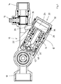
- Fig.1Fig.1
- ist eine geschnittene Ansicht durch einen Druckminderer in geöffneter Stellungis a sectional view through a pressure reducer in the open position
- Fig.2Fig.2
- ist eine vergrößerte Ansicht des Druckminderers aus Fig. 1 in geschlossener Stellungis an enlarged view of the pressure reducer of Fig. 1 in the closed position
- Fig.3Figure 3
- zeigt den Druckminderer aus Fig.2 in geöffneter Stellungshows the pressure reducer of Figure 2 in the open position
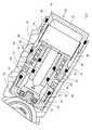
- Fig.4Figure 4
- zeigt einen Druckminderer, der in eine Rohrleitung eingebaut ist.shows a pressure reducer, which is installed in a pipeline.
In Fig. 1 ist eine Armatur 10 mit einem Druckminderer 12 dargestellt. Die Armatur 10 umfasst einen Einlass 14 zum Anschluß an eine Trinkwasserversorgung (nicht dargestellt). Der Einlass 14 ist mit einem Absperrhahn 16 absperrbar. Zwischen dem Absperrhahn 16 und einem Auslass 18 ist der allgemein mit 12 bezeichnete Druckminderer vorgesehen. Der Druckminderer 12 ist in einem an das Armaturengehäuse 22 angeformten Gehäuseteil 20 angeordnet. Das Wasser fließt vom Einlass 14 durch einen Kanal 24 in einen Eingangskammer 26. Der Gehäuseteil 20 ist rohrförmig ausgebildet, wobei die Mittenachse einen Winkel mit der Mittenachse des übrigen Gehäuses bildet. Im Bereich der Eingangskammer 26 ist ein zylindrisches Schmutzsieb 28 angeordnet, welches die Eingangskammer 26 von dem Kanal 24 abdeckt. Der Gehäuseteil 20 ist an einem Ende 30 mit einem abnehmbaren Deckel 32 versehen. Auf diese Weise wird das Innere des rohrförmigen Gehäuseteils 20 z.B. zu Wartungszwecken oder zum Austauschen des Druckminderers zugänglich.In Fig. 1, a
Der Druckminderer umfasst eine gehäusefeste Ventilteller-Baugruppe und eine bewegliche Ventilsitzkörper-Baugruppe (Fig.2). Die gehäusefeste Ventilteller-Baugruppe umfasst eine Ventilspindel 34. Die Ventilspindel 34 ist langgestreckt und mit einer axialen Mittenbohrung 36 versehen. Die Mittenbohrung 36 mündet einlaßsseitig in der Eingangskammer 26.The pressure reducer comprises a housing-fixed valve disk assembly and a movable valve seat body assembly (Figure 2). The housing-fixed valve disc assembly comprises a
Einlaßseitig ist konzentrisch um die Ventilspindel herum ein topfförmiger Federwiderlagerkörper 38 vorgesehen, der auf die Ventilspindel 34 aufgeschraubt ist. Der Federwiderlagerkörper 38 weist im Bereich der Bohrung 36 ebenfalls einen Durchgang auf. Das andere, auslaßseitige Ende 40 der Ventilspindel 34 ist etwas verbreitert. In diesem so gebildeten Kopf ist eine als Ventilteller wirkendes Dichtteil 42 eingeschraubt. Das Dichtmittel wirkt mit einer Dichtung 44 zusammen, die in einer Ringnut im Kopf 40 der Ventilspindel 34 angeordnet ist.On the inlet side, a pot-shaped
Zwischen dem topfförmigen Federwiderlagerkörper 38 und der damit fest verbundenen Ventilspindel 34 ist eine Dichtung 46 in Form eines O-Rings angeordnet. Der Federwiderlagerkörper 38 ist mit einer stromabwärts offenen, tiefe Ringnut 48 versehen.Between the pot-shaped
Durch die Ringnut 48 werden zwei konzentrische, zylindrische Wandungen 52 und 54 gebildet. In der Ringnut 48 ist eine Schraubenfeder 50 angeordnet, die sich am Ende der Ringnut 48 in dem Federwiderlagerkörper 38 abstützt. Der Federwiderlagerkörper ist mit einer Dichtung 58 gegen das Gehäuse 20 abgedichtet und mit diesem verschraubt. Im Bereich der Feder 50 herrscht Atmosphärendruck, da er über eine Öffnung 51 mit dem Außenraum des Gehäuses verbunden ist.Through the
Die Feder 52 wirkt auf die Ventilsitz-Baugruppe. Diese ist auf der gehäusefesten Ventilspindel 34 beweglich geführt. Die Ventilsitz-Baugruppe umfasst eine Schiebehülse 60 und einen darauf aufgeschraubten Ventilsitzkörper 62. Der Ventilsitzkörper 62 ist topfförmig und wirkt zusammen mit dem Ventilteller 42 als Regelventil. Zwischen Ventilsitzkörper 62 und Schiebehülse 60 ist eine Dichtung 64 angeordnet.The
Die Schiebehülse 60 ist im wesentlichen rohrförmig. Sie ist mit dem stromaufwärtigen Teil auf der Ventilspindel 34 geführt und mit einer Dichtung 66 gegen diese abgedichtet. Der Innendurchmesser der Schiebehülse 62 verbreitert sich im Bereich des Kopfes der Ventilspindel 34. Dadurch wird zwischen Ventilspindel 34 und Schiebehülse 62 ein Hohlraum 68 im Bereich vor dem Ventil gebildet. Die Schraubenfeder 52 drückt gegen die Schiebehülse.The sliding
Die Schiebehülse weist außen eine Ringnut auf, in der eine Dichtung 70 vorgesehen ist, mit der die Schiebehülse gegenüber dem Gehäuse 20 abgedichtet wird.The sliding sleeve has on the outside an annular groove in which a
Die Ventilspindel 34 weist vor dem Bereich des Kopfes eine radial verlaufende Querbohrung 72 auf. Diese ist in Fig. 4, das ein weiteres Ausführungsbeispiel zeigt, in einem anderen Schnitt ebenfalls zu erkennen. Über die Querbohrung 72 und den Kanal 36 steht der Raum vor dem Ventil mit der Eingangskammer 26 in Verbindung.The
Der Druckminderer arbeitet wie folgt:The pressure reducer works as follows:
Der Ausgangsdruck im Ausgang wirkt auf die ringförmige, äußere Stirnfläche des Ventilsitzkörpers 62 der Kraft der Schraubenfeder 52 entgegen. Dadurch wird die Ventilsitz-Baugruppe aus Ventilsitzkörper 62 und Schiebehülse 60 nach links oben in Fig.2 gedrückt. Der Ringspalt des Regelventils zwischen dem feststehenden Ventilteller 42 und dem Ventilsitz 74 des Ventilsitzkörpers 62 wird gedrosselt. Sinkt der Ausgangsdruck im Auslass, dann wird die Kraft auf den Ventilsitzkörper 62 geringer. Die Kraft der Schraubenfeder 50 überwindet den Auslaßdruck und bewegt die Ventilsitz-Baugruppe nach links oben in Fig.1, also vom feststehenden Ventilteller 42 weg. Dadurch wird der Ringspalt vergrößert, so daß der Ausgangsdruck wieder ansteigen kann. Diese Situation ist in Fig.3 dargestellt. Der auf den Ventilteller wirksame Ausgangsdruck wird von der Ventilspindel 34 und über diese vom Gehäuse aufgenommen.The outlet pressure in the outlet counteracts the annular, outer face of the
Das in den Figuren 1 bis 3 dargestellte Ausführungsbeispiel zeigt eine Variante, bei der die gesamte Druckminderer-Anordnung unter einem Winkel in eine Armatur eingebaut ist. Die Anordnung ist dadurch über den Deckel 32 jederzeit zugänglich. Die Armatur kann aber bei entsprechender Dimensionierung direkt in eine Rohrleitung eingebaut werden. Dies ist in Fig. 4 gezeigt.The embodiment shown in Figures 1 to 3 shows a variant in which the entire pressure reducer assembly is installed at an angle in a valve. The arrangement is thus accessible via the
Da Einlaß und Auslaß 78 an den jeweiligen Enden der Druckminderer-Anordnung 80 vorgesehen sind, kann eine lineare Anordnung erreicht werden, ohne daß seitliche Kanäle vorgesehen sind.Since inlet and
Claims (5)
Applications Claiming Priority (1)
| Application Number | Priority Date | Filing Date | Title |
|---|---|---|---|
| DE200510052385 DE102005052385B4 (en) | 2005-10-31 | 2005-10-31 | pressure reducer |
Publications (2)
| Publication Number | Publication Date |
|---|---|
| EP1780452A2 true EP1780452A2 (en) | 2007-05-02 |
| EP1780452A3 EP1780452A3 (en) | 2007-11-28 |
Family
ID=37663350
Family Applications (1)
| Application Number | Title | Priority Date | Filing Date |
|---|---|---|---|
| EP20060120367 Withdrawn EP1780452A3 (en) | 2005-10-31 | 2006-09-08 | Pressure reducer |
Country Status (5)
| Country | Link |
|---|---|
| US (1) | US20070095402A1 (en) |
| EP (1) | EP1780452A3 (en) |
| AU (1) | AU2006230770A1 (en) |
| DE (1) | DE102005052385B4 (en) |
| ZA (1) | ZA200608993B (en) |
Cited By (5)
| Publication number | Priority date | Publication date | Assignee | Title |
|---|---|---|---|---|
| FR2917147A1 (en) * | 2007-06-11 | 2008-12-12 | Perolo Sa Sa | SAFETY VALVE AND TANK CONTAINER EQUIPPED WITH SUCH A VALVE |
| DE102009030182A1 (en) * | 2009-06-24 | 2011-01-05 | Neoperl Gmbh | Valve |
| EP2515021A3 (en) * | 2011-04-18 | 2012-12-26 | Hans Sasserath & Co Kg | Pressure reducer filter assembly with leakage protection |
| CN108426044A (en) * | 2018-03-29 | 2018-08-21 | 卢星霖 | Dual body core tube valve |
| CN108488403A (en) * | 2018-03-29 | 2018-09-04 | 卢星霖 | core pipe valve |
Families Citing this family (3)
| Publication number | Priority date | Publication date | Assignee | Title |
|---|---|---|---|---|
| CN102966774A (en) * | 2012-11-14 | 2013-03-13 | 金祖贻 | Pressure reducing valve |
| US9518670B2 (en) * | 2013-03-15 | 2016-12-13 | David E Albrecht | Main stage in-line pressure control cartridge with stepped retainer collar |
| WO2016205043A1 (en) * | 2015-06-14 | 2016-12-22 | Albrecht David E | Main stage in-line pressure control cartridge with stepped retainer collar |
Citations (4)
| Publication number | Priority date | Publication date | Assignee | Title |
|---|---|---|---|---|
| FR1216484A (en) | 1958-11-27 | 1960-04-26 | Regulator for compressed or liquefied gases or any other fluids | |
| DE3504785A1 (en) | 1984-03-01 | 1985-10-17 | Barmag Barmer Maschinenfabrik Ag, 5630 Remscheid | Pressure regulating valve |
| FR2754584A1 (en) | 1996-10-15 | 1998-04-17 | Comap Sdh | Pressure reducer for fluid distribution installation |
| EP1431857A2 (en) | 2002-12-17 | 2004-06-23 | Hans Sasserath & Co Kg | Pressure reducing assembly |
Family Cites Families (6)
| Publication number | Priority date | Publication date | Assignee | Title |
|---|---|---|---|---|
| US1038527A (en) * | 1912-02-24 | 1912-09-17 | Conrad Hubert | Needle-valve. |
| US3131715A (en) * | 1962-06-08 | 1964-05-05 | Lawrence M Sanders | Hydraulic braking accessory |
| DE4237451A1 (en) * | 1992-11-06 | 1994-05-11 | Teves Gmbh Alfred | Hydraulic pressure reducing valve |
| US5685297A (en) * | 1996-02-13 | 1997-11-11 | Schuler; Manfred | Freeze resistant liquid filled first stage scuba regulator |
| KR100215236B1 (en) * | 1996-06-17 | 1999-08-16 | 오상수 | Hydraulic supply device for vehicle driving force control |
| US20040007269A1 (en) * | 2002-07-12 | 2004-01-15 | Larsen Todd W. | Inline pressure reducing regulator |
-
2005
- 2005-10-31 DE DE200510052385 patent/DE102005052385B4/en not_active Expired - Fee Related
-
2006
- 2006-09-08 EP EP20060120367 patent/EP1780452A3/en not_active Withdrawn
- 2006-10-24 AU AU2006230770A patent/AU2006230770A1/en not_active Abandoned
- 2006-10-30 US US11/590,138 patent/US20070095402A1/en not_active Abandoned
- 2006-10-30 ZA ZA200608993A patent/ZA200608993B/en unknown
Patent Citations (4)
| Publication number | Priority date | Publication date | Assignee | Title |
|---|---|---|---|---|
| FR1216484A (en) | 1958-11-27 | 1960-04-26 | Regulator for compressed or liquefied gases or any other fluids | |
| DE3504785A1 (en) | 1984-03-01 | 1985-10-17 | Barmag Barmer Maschinenfabrik Ag, 5630 Remscheid | Pressure regulating valve |
| FR2754584A1 (en) | 1996-10-15 | 1998-04-17 | Comap Sdh | Pressure reducer for fluid distribution installation |
| EP1431857A2 (en) | 2002-12-17 | 2004-06-23 | Hans Sasserath & Co Kg | Pressure reducing assembly |
Cited By (9)
| Publication number | Priority date | Publication date | Assignee | Title |
|---|---|---|---|---|
| FR2917147A1 (en) * | 2007-06-11 | 2008-12-12 | Perolo Sa Sa | SAFETY VALVE AND TANK CONTAINER EQUIPPED WITH SUCH A VALVE |
| EP2003380A1 (en) * | 2007-06-11 | 2008-12-17 | Perolo S.A. | Safety valve and tank container equipped with such a valve |
| DE102009030182A1 (en) * | 2009-06-24 | 2011-01-05 | Neoperl Gmbh | Valve |
| WO2010149313A3 (en) * | 2009-06-24 | 2011-04-21 | Neoperl Gmbh | Valve |
| US8919373B2 (en) | 2009-06-24 | 2014-12-30 | Neoperl Gmbh | Valve |
| EP2515021A3 (en) * | 2011-04-18 | 2012-12-26 | Hans Sasserath & Co Kg | Pressure reducer filter assembly with leakage protection |
| CN108426044A (en) * | 2018-03-29 | 2018-08-21 | 卢星霖 | Dual body core tube valve |
| CN108488403A (en) * | 2018-03-29 | 2018-09-04 | 卢星霖 | core pipe valve |
| CN108426044B (en) * | 2018-03-29 | 2019-07-05 | 卢星霖 | Double body core tube valve |
Also Published As
| Publication number | Publication date |
|---|---|
| EP1780452A3 (en) | 2007-11-28 |
| US20070095402A1 (en) | 2007-05-03 |
| AU2006230770A1 (en) | 2007-05-17 |
| DE102005052385A1 (en) | 2007-05-24 |
| DE102005052385B4 (en) | 2008-07-10 |
| ZA200608993B (en) | 2008-06-25 |
Similar Documents
| Publication | Publication Date | Title |
|---|---|---|
| DE2450094A1 (en) | SLIDER | |
| EP0487944B1 (en) | Safety valve | |
| DE4310232C2 (en) | Emergency shutdown valve with regulator | |
| EP1741843B1 (en) | Backflow prevention assembly | |
| EP2527700A1 (en) | Valve | |
| DE102005052385B4 (en) | pressure reducer | |
| EP0401468B1 (en) | Valve arrangement for the simultaneous opening and closing of two separated supply pipes for liquid or gaseous agents | |
| DE2926320C2 (en) | Electromagnetically operated membrane water valve with a hydraulic servo unit for regulating the water cycle in heating and air conditioning systems | |
| EP2644788B1 (en) | Pipe splitting device | |
| EP1852642B1 (en) | Safety valve | |
| EP1429064A1 (en) | Solenoid pilot valve | |
| EP0151563A2 (en) | Solenoid valve | |
| EP3561350B1 (en) | Vacuum relief valve | |
| DE19705200C1 (en) | No=return valve | |
| EP0353266A1 (en) | Nonreturn valve, in particular for incorporation in drinking water pipes | |
| EP2644789B1 (en) | Modular kit for pipe splitting devices | |
| DE202012101123U1 (en) | Pipe separator arrangement | |
| DE19636410B4 (en) | Faucet for water pipes | |
| DE2259079B1 (en) | Valve, especially float-controlled condensate drain | |
| DE2503302A1 (en) | FLOAT CONTROLLED VALVE | |
| DE102006030973B3 (en) | Fluid system separator, has load spring causing spring force over lifting unit when inlet side stopper of spring is provided on exhaust valve body so that spring acts on lifting unit and serves as load spring for valve body | |
| EP1503123B1 (en) | Upper part of a valve | |
| CH642434A5 (en) | VALVE. | |
| DE10045120B4 (en) | Bottle closure device | |
| DE10259205A1 (en) | Pressure reducer assembly |
Legal Events
| Date | Code | Title | Description |
|---|---|---|---|
| PUAI | Public reference made under article 153(3) epc to a published international application that has entered the european phase |
Free format text: ORIGINAL CODE: 0009012 |
|
| AK | Designated contracting states |
Kind code of ref document: A2 Designated state(s): AT BE BG CH CY CZ DE DK EE ES FI FR GB GR HU IE IS IT LI LT LU LV MC NL PL PT RO SE SI SK TR |
|
| AX | Request for extension of the european patent |
Extension state: AL BA HR MK YU |
|
| PUAL | Search report despatched |
Free format text: ORIGINAL CODE: 0009013 |
|
| AK | Designated contracting states |
Kind code of ref document: A3 Designated state(s): AT BE BG CH CY CZ DE DK EE ES FI FR GB GR HU IE IS IT LI LT LU LV MC NL PL PT RO SE SI SK TR |
|
| AX | Request for extension of the european patent |
Extension state: AL BA HR MK YU |
|
| 17P | Request for examination filed |
Effective date: 20071221 |
|
| 17Q | First examination report despatched |
Effective date: 20080124 |
|
| AKX | Designation fees paid |
Designated state(s): AT BE BG CH CY CZ DE DK EE ES FI FR GB GR HU IE IS IT LI LT LU LV MC NL PL PT RO SE SI SK TR |
|
| STAA | Information on the status of an ep patent application or granted ep patent |
Free format text: STATUS: THE APPLICATION IS DEEMED TO BE WITHDRAWN |
|
| 18D | Application deemed to be withdrawn |
Effective date: 20100401 |