EP3399218B1 - Anordnung zur leitung, behandlung und/oder messung eines fluids - Google Patents
Anordnung zur leitung, behandlung und/oder messung eines fluids Download PDFInfo
- Publication number
- EP3399218B1 EP3399218B1 EP18000345.1A EP18000345A EP3399218B1 EP 3399218 B1 EP3399218 B1 EP 3399218B1 EP 18000345 A EP18000345 A EP 18000345A EP 3399218 B1 EP3399218 B1 EP 3399218B1
- Authority
- EP
- European Patent Office
- Prior art keywords
- functional unit
- core piece
- connection
- arrangement
- inlet
- Prior art date
- Legal status (The legal status is an assumption and is not a legal conclusion. Google has not performed a legal analysis and makes no representation as to the accuracy of the status listed.)
- Active
Links
Images



Classifications
-
- E—FIXED CONSTRUCTIONS
- E03—WATER SUPPLY; SEWERAGE
- E03B—INSTALLATIONS OR METHODS FOR OBTAINING, COLLECTING, OR DISTRIBUTING WATER
- E03B7/00—Water main or service pipe systems
- E03B7/07—Arrangement of devices, e.g. filters, flow controls, measuring devices, siphons or valves, in the pipe systems
-
- F—MECHANICAL ENGINEERING; LIGHTING; HEATING; WEAPONS; BLASTING
- F16—ENGINEERING ELEMENTS AND UNITS; GENERAL MEASURES FOR PRODUCING AND MAINTAINING EFFECTIVE FUNCTIONING OF MACHINES OR INSTALLATIONS; THERMAL INSULATION IN GENERAL
- F16K—VALVES; TAPS; COCKS; ACTUATING-FLOATS; DEVICES FOR VENTING OR AERATING
- F16K5/00—Plug valves; Taps or cocks comprising only cut-off apparatus having at least one of the sealing faces shaped as a more or less complete surface of a solid of revolution, the opening and closing movement being predominantly rotary
- F16K5/04—Plug valves; Taps or cocks comprising only cut-off apparatus having at least one of the sealing faces shaped as a more or less complete surface of a solid of revolution, the opening and closing movement being predominantly rotary with plugs having cylindrical surfaces; Packings therefor
- F16K5/0407—Plug valves; Taps or cocks comprising only cut-off apparatus having at least one of the sealing faces shaped as a more or less complete surface of a solid of revolution, the opening and closing movement being predominantly rotary with plugs having cylindrical surfaces; Packings therefor with particular plug arrangements, e.g. particular shape or built-in means
-
- E—FIXED CONSTRUCTIONS
- E03—WATER SUPPLY; SEWERAGE
- E03B—INSTALLATIONS OR METHODS FOR OBTAINING, COLLECTING, OR DISTRIBUTING WATER
- E03B7/00—Water main or service pipe systems
- E03B7/07—Arrangement of devices, e.g. filters, flow controls, measuring devices, siphons or valves, in the pipe systems
- E03B7/075—Arrangement of devices for control of pressure or flow rate
-
- E—FIXED CONSTRUCTIONS
- E03—WATER SUPPLY; SEWERAGE
- E03B—INSTALLATIONS OR METHODS FOR OBTAINING, COLLECTING, OR DISTRIBUTING WATER
- E03B7/00—Water main or service pipe systems
- E03B7/09—Component parts or accessories
- E03B7/095—Component holders or housings, e.g. boundary boxes
-
- F—MECHANICAL ENGINEERING; LIGHTING; HEATING; WEAPONS; BLASTING
- F16—ENGINEERING ELEMENTS AND UNITS; GENERAL MEASURES FOR PRODUCING AND MAINTAINING EFFECTIVE FUNCTIONING OF MACHINES OR INSTALLATIONS; THERMAL INSULATION IN GENERAL
- F16K—VALVES; TAPS; COCKS; ACTUATING-FLOATS; DEVICES FOR VENTING OR AERATING
- F16K5/00—Plug valves; Taps or cocks comprising only cut-off apparatus having at least one of the sealing faces shaped as a more or less complete surface of a solid of revolution, the opening and closing movement being predominantly rotary
- F16K5/04—Plug valves; Taps or cocks comprising only cut-off apparatus having at least one of the sealing faces shaped as a more or less complete surface of a solid of revolution, the opening and closing movement being predominantly rotary with plugs having cylindrical surfaces; Packings therefor
- F16K5/0457—Packings
-
- F—MECHANICAL ENGINEERING; LIGHTING; HEATING; WEAPONS; BLASTING
- F16—ENGINEERING ELEMENTS AND UNITS; GENERAL MEASURES FOR PRODUCING AND MAINTAINING EFFECTIVE FUNCTIONING OF MACHINES OR INSTALLATIONS; THERMAL INSULATION IN GENERAL
- F16K—VALVES; TAPS; COCKS; ACTUATING-FLOATS; DEVICES FOR VENTING OR AERATING
- F16K5/00—Plug valves; Taps or cocks comprising only cut-off apparatus having at least one of the sealing faces shaped as a more or less complete surface of a solid of revolution, the opening and closing movement being predominantly rotary
- F16K5/02—Plug valves; Taps or cocks comprising only cut-off apparatus having at least one of the sealing faces shaped as a more or less complete surface of a solid of revolution, the opening and closing movement being predominantly rotary with plugs having conical surfaces; Packings therefor
- F16K5/0257—Packings
Definitions
- the present invention relates to an arrangement for installation in a pipeline of a fluid network, according to the preamble of claim 1.
- Generic arrangements are z. B. used in drinking water networks to connect additional functional units to the drinking water installation by appropriate specialist staff.
- connection housing installed in a pipeline.
- the connection housing comprises an access opening which is open on one side and into which an obturator with a receiving space and with an inlet and outlet can be rotatably inserted.
- a cylindrical filter insert is located inside the obturator.
- a cover is provided on the upper side which has projections on the lower side which engage in recesses on the upper side of the obturator, so that the obturator and the filter insert can be rotated by turning the cover.
- the cover is fixed to the connection housing in that radially circumferential projections engage in radially circumferential grooves on the upper part of the connection housing. As a result, the obturator is held in the recess of the connection housing.
- connection piece for installation in a pipe or water line and a connection arrangement consisting of several connection pieces.
- the connection piece has an inlet and an outlet which are arranged opposite one another along an axis.
- the connection piece is inserted into the pipeline by means of the inlet and outlet.
- Functional units such as B. water softener or water filter, can be connected to the connector.
- the respective connection piece is constructed in such a way that the water first flows through the connection piece and then through the water treatment devices from the connection piece. This ensures that water passes through both water treatment devices as it flows through the connector. However, no water flow can occur once one of the water treatment devices is removed or defective. In the event of an expansion or defect, the water flow must, for. B. locked via a main shutdown.
- the installation and installation of the functional units by flanging are cumbersome, require maintenance and require opening of the water system.
- the U.S. 5,706,851 A discloses a valve for high temperature applications in a direct reduction reactor system having a valve housing comprising a cylindrical body and flanges connected thereto.
- the valve housing is intended for installation in a pipeline.
- the valve housing comprises an inlet and an outlet as well as a connection opening for connecting a cylindrical plug.
- an exchangeable cylindrical wear part with openings is provided in the valve housing which, when the wear part is rotated, block or release the inlet and outlet of the valve depending on their position.
- the wearing part has a receptacle for connecting the plug, the receptacle and the connection opening of the valve housing being oriented in the same direction. The plug is inserted into the wearing part.
- the wear part is rotated by rotating the plug arranged in the wear part, whereby the flow through the valve housing and the wear part can be released and / or blocked by rotating the plug.
- a cover rotates the wear part on the valve housing.
- the plug and the cover have means for producing a mechanically releasable connection between the plug and the cover.
- the object of the present invention is to provide an arrangement in which additional functions can be installed and uninstalled in a simple manner, quickly and with little maintenance with improved security.
- connection housing has a rotatably arranged core piece, through the rotation of which the flow of the fluid through the connection housing can be blocked or released.
- the core piece comprises a receptacle which is prepared for connecting a functional unit.
- the receptacle and the connection opening are oriented in the same direction, d. H. in the connection direction of the functional unit, so that the functional unit can engage in the receptacle when connected.
- This enables the functional unit to be inserted directly into the receptacle of the core.
- the flow through the connection housing and the core piece is released and / or blocked, so that the work steps of installing or uninstalling the functional unit also include blocking and / or releasing the flow.
- This allows additional functions to be implemented by the user in a simple manner and without additional specialist staff.
- the security during the installation and deinstallation of the functional unit or the additional function is improved to a particular degree.
- the inlet and the outlet can preferably be arranged along a flow axis, wherein the connection direction of the functional unit can run orthogonally to the flow axis. Accordingly, the functional unit or at least part of the functional unit can be positioned in the area of the flow axis. As a result, fluid either flows through the functional unit or the fluid can be conducted in the direction opposite to the connection direction in the direction of the functional unit.
- the core piece expediently comprises a core piece inlet and a core piece outlet, which are preferably arranged opposite one another, so that the fluid can flow through the core piece through the inlet of the connection housing are connected to the core piece inlet and the outlet of the connection housing with the core piece outlet.
- the core piece inlet and the core piece outlet can each be connected to the receptacle.
- the core piece inlet and the core piece outlet can be coupled to the functional unit engaging in the receptacle, so that the fluid can be conducted through or past the functional unit.
- additional functions can be implemented via the functional unit, which optionally require fluid contact or a flow through with fluid or no fluid contact.
- the core piece can be oriented in such a way that the inlet, the outlet, the core piece inlet and the core piece outlet are arranged along a common axis, in particular along the flow axis.
- connection housing has a corresponding, in particular cylindrical or spherical, recess into which the core piece can be inserted.
- a sealing element can be provided in the area of the inlet and / or the outlet, which seals the connection housing against the core piece.
- the sealing element is adapted to the preferably cylindrical or spherical or flattened spherical contour of the core piece.
- the sealing element can, for. B. can be used in a simple manner in the inlet or the outlet of the connection housing or connected to it. Such sealing elements make the entire arrangement particularly safe Dimensions improved.
- the sealing element can also be arranged on the core piece.
- the sealing element preferably comprises a sealing means acting radially, in particular against the connection housing, and a sealing means acting axially, in particular against the core piece.
- an O-ring can be provided as a sealing means, the z. B rubber, polytetrafluoroethylene (PTFE), perfluorinated rubber (FFKM, FFPM) or polyethylene (PE).
- the core piece is rotatably held within the connection housing via a holder.
- a cover or retaining ring can be provided as the holder, which is fastened to corresponding fastening means (e.g. a thread) of the connection housing via fastening means (e.g. screws, pins or bolts).
- the holder is arranged in such a way that the rotational movement of the core piece is not prevented. This ensures that the core piece is securely fastened on and / or in the connection housing without restricting the rotary function.
- the core can easily be replaced by deinstalling the holder.
- the holder itself can also comprise a thread with which it can be screwed onto a corresponding thread on the connection housing.
- the functional unit is connected to the receptacle.
- it can engage in the receptacle, preferably in a form-fitting manner.
- the core piece is rotated by rotating the functional unit connected to the receptacle, by ensuring that the rotational movement is transmitted from the functional unit to the core piece.
- the functional unit is designed in such a way that it can be locked in at least one rotational position or can be locked with the holder. As a result, the functional unit is held in position even when there is fluid pressure, which further improves safety.
- the functional unit and the holder have means for establishing a mechanically releasable connection between the functional unit and the holder. This has the advantage that the functional unit can be attached to the holder.
- Projections which engage in corresponding recesses in the connection housing and / or the holder, are preferably provided as means for establishing a mechanically releasable connection on the functional unit.
- the projections are designed in such a way that they can only be inserted into the recesses in one orientation according to a key-lock principle.
- additional configurations of the recesses such as. B. different grooves or groove shapes, L-shaped recesses can be provided, through which the support function is further improved.
- a bayonet lock is provided as the means for establishing a mechanically releasable connection or locking, the connecting elements such.
- B. an angled recess and an insertable into the angled recess projection are arranged on the functional unit and the bracket.
- the functional unit can expediently have a flow channel which, in the connected state, is located inside the core piece and is connected to the core piece inlet and the core piece outlet, so that a flow through the functional unit is made possible.
- the functional unit z. B a functional device within the flow channel, e.g. B. a filter, or a function module which includes the desired additional function.
- the functional unit can be, for example, a placeholder functional unit, a decalcifying functional unit, a filter functional unit, a monitoring functional unit, a germ reduction functional unit, a pressure reducing and / or pressure regulating functional unit, a functional unit for Determination of chemical and / or microbiological parameters, a data functional unit z. B. for storing data, a communication functional unit z. B.
- a display functional unit and / or a functional unit to determine the pH value, electrical conductivity, nitrate, nitrite, sulfate, carbon dioxide, iron, fluoride, chlorine, copper, phosphate, silicon, ammonium, hardness , Flow rate, temperature, carbonate, salt content, germ content and / or metal content.
- Sealing means are preferably provided on the functional unit and / or in the area of the functional unit on the core piece, such as. B. O-rings that seal the core against the functional unit.
- the fluid can flow through the core piece and the functional unit without fluid escaping at the transitions between the individual units.
- the operational reliability of the arrangement is further improved by this configuration.
- the functional unit has its own connection geometry.
- the functional unit can be connected in a simple manner as a modular component pre-assembled by the manufacturer to the connection housing, the receptacle for the core and / or the holder.
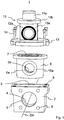
- Reference number 1 in Fig. 1 denotes an arrangement according to the invention for conducting, treating and / or determining parameters or measuring a fluid.
- the arrangement 1 is part of a, in Fig. 1 not shown, fluid line network such. B. a drinking water supply network.
- the arrangement 1 comprises a connection housing 2, which has an inlet 3 and an outlet 4, by means of which the connection housing 2 z. B. can be used in a pipeline of the fluid line network. This can be done, for example, by means of connecting means that engage in threaded bores 9 of the connection housing 2 and are not shown in the figures.
- the direction of flow of the fluid is generally from inlet 3 to outlet 4 along a flow axis DA.
- connection housing 2 has a connection opening 5 to which, for. B. a functional unit 10 can be connected.
- a connection opening 5 to which, for. B. a functional unit 10 can be connected.
- a rotatably arranged, cylindrical core piece 6 is provided below the connection opening 5. Consequently the core piece 6 can be easily inserted into the cylindrical recess of the connection housing 2 via the connection opening 5 during assembly.
- the core piece 6 comprises a core piece inlet 6a and an oppositely arranged core piece outlet 6b, by means of which the fluid can flow through the core piece 6 from the core piece inlet 6a to the core piece outlet 6b along the flow axis DA.
- the flow of the fluid through the connection housing 2 can be blocked by rotating the core piece 6, by rotating the core piece inlet 6a and the core piece outlet 6b by rotating the core piece 6 out of alignment of inlet 3 and outlet 4, i.e. out of the flow axis DA will. Accordingly, the flow of the fluid through the connection housing 2 can be released again in that the core piece inlet 6a and the core piece outlet 6b are rotated into the flow axis DA by rotating the core piece 6.
- the core piece 6 has a receptacle 7 which, like the connection opening 5, is oriented in the direction of the functional unit 10, ie in the same direction. As a result, the functional unit 10 can engage in the receptacle 7 in the connected state.
- the core piece inlet 6a and the core piece outlet 6b are each connected to the receptacle 7 so that the fluid can flow in the direction of the functional unit 10.
- the functional unit 10 is optionally set up for conducting, treating and / or determining parameters of the fluid.
- the functional unit 10 as in FIG Fig. 1 shown, a function module 11a, the z. B. means for decalcifying, filtering, pressure reduction, monitoring, germ reduction, determination of chemical and microbiological parameters, determination of pH value, electrical conductivity, nitrate, nitrite, sulfate, carbon dioxide, iron, fluoride, chlorine, copper, phosphate, silicon, ammonium , Hardness, temperature, flow rate, carbonate, salt content, germ content or metal content, data storage, communication e.g. B. includes via radio and / or display.
- the functional unit 10 comprises an insert 10a, which preferably engages positively in the receptacle 7 of the core piece 6 and has a flow channel that connects the core piece inlet 6a and the core piece outlet 6b and through which fluid flows.
- the functional unit 10 or the Insert 10a a sealant 12a and a, in Fig. 1 Sealing means 12b, not shown, which seal the functional unit 10 against the core piece 6.
- the insert 10a can also preferably be arranged within the functional unit 10, in Fig. 1 Not shown, include inlet and outlet channels that guide the fluid to the functional module 11a.
- a cover 10b is provided, which is designed to fasten the functional module 10 to the connection housing 2.
- the core piece 6 can expediently be held rotatably within the connection housing 2 via a holder 13, in that the holder 13 pretensions the cover 10b against the core piece 6 or the connection housing 2.
- the bracket 13 z. B. fastened to the connection housing 2 via screws 14 and threaded holes 8.
- a clamping ring or another type of fastening known from the prior art can also be provided.
- FIG. 2 a further advantageous embodiment of the present invention is shown.
- the arrangement 1 has two sealing elements 15a, 15b, which are arranged in the area of the inlet 3 and the outlet 4 and serve to seal the connection housing 2 against the core piece 6 via sealing means 16a, 16b, 17a, 17b.
- the sealing elements 15a, 15b can also, as in FIG Fig. 1 shown, are arranged within the core piece 6.
- the functional unit 10 in Fig. 2 has a handle 11b instead of the function module 11a, and thus only serves as a placeholder module which enables fluid to flow through without performing fluid treatment or parameter measurement, ie only has a fluid-conducting function.
- the arrangement 1 in Fig. 2 be equipped with any other mentioned functional unit 10 for the management, treatment and / or parameter determination of the fluid.
- the functional unit 10 is inserted into the receptacle 7 of the core piece 6 in a simple manner along the connection direction AR.
- Fig. 3 the course of the flow axis DA and the axis of the connection direction AR of the functional unit is shown.
- the flow axis DA and the connection direction AR are preferably arranged in such a way that they run essentially orthogonally to one another.
- the functional unit 10 and the holder 13 have means for producing a mechanically releasable connection between the functional unit 10 and the connection housing 2 or the holder 13.
- Projections 18a, 18b, 18c, which engage in corresponding recesses 19a, 19b, 19c of holder 13, are provided on functional unit 10 as means.
- this is a bayonet lock which makes it possible to fix the functional unit 10 by inserting it into the core piece 6 and then rotating it through, for example, 45 ° within the core piece 6 and to restrict the rotational movement of the core piece 6.
- the bayonet lock is also designed to apply bias to sealing elements, such as. B. exercise sealant 12a, 12b, 17a, 17b.
- the core piece 6 is also rotated, as a result of which the flow through the connection housing 2 and the core piece 6 is released and / or blocked.
- the installation or deinstallation of the functional unit 10 thus also includes the blocking and / or releasing of the flow through the connection housing 2, ie the arrangement 1 according to the invention also includes a shut-off mechanism for the pipeline.
- the arrangement 1 thus provides a mechanism for the modular installation of functional units 10 or functions in the fluid line network.
- the user can set a standard fluid flow (e.g. using the placeholder module, in which fluid flows unhindered and unaffected through the fitting), a fluid deflection (e.g. using a deflection through a functional module 11a with fluid influencing and / or parameter measurement) or a fluid stop (for example with the functional unit 10 being uninstalled or a certain position or a certain angle of rotation of the core piece 6).
- a standard fluid flow e.g. using the placeholder module, in which fluid flows unhindered and unaffected through the fitting
- a fluid deflection e.g. using a deflection through a functional module 11a with fluid influencing and / or parameter measurement
- a fluid stop for example with the functional unit 10 being uninstalled or a certain position or a certain angle of rotation of the core piece 6.
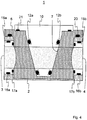
- the arrangement 1 comprises various sealing elements, the arrangement of which is essentially in Fig. 4 is shown by means of a sectional view.
- the fluid is in Fig. 4 represented by a dotted hatching.
- the functional unit 10 is in the area via two sealing means 12a, 12b of the fluid flow and an additional O-ring 21 in the area of the receptacle 7 is sealed against the core piece 6.
- the O-ring 21 merely represents an additional sealing measure and is therefore not mandatory.
- the core piece 6 can also be sealed against the connection housing 2 via an additional O-ring 20.
- sealing elements may be provided, which, for. B. seal the core 6 against the connection housing 2.
- the sealing elements 15a, 15b each comprise a sealing means 16a, 16b acting radially against the connection housing 2 and a sealing means 17a, 17b acting axially against the core piece 6.
- an O-ring is preferably used as sealing means 16a, 16b, 17a, 17b. This creates a sealing concept which seals the cylindrical surface of the core piece 6 and at the same time allows the rotating mechanism to function, in that the sealing element 15a, 15b and the sealing means 17a, 17b acting axially against the core piece 6 are adapted to the contour of the core piece 6.
- a faultless installation (according to "Poka-Yoke") of the functional unit can be realized by z. B.
- the projections 18a, 18b, 18c are designed such that they only in one orientation z. B. according to a key and lock principle in the recesses 19a, 19b, 19c can be used.
- Fig. 5 Shown using a simplified plan view of the functional unit 10 and the bracket 13, this can be done, for. B. can be realized over the width of the projections 18a, 18b, 18c.
- the outlines or the number of projections 18a, 18b, 18c and recesses 19a, 19b, 19c can also vary.
- the arrangement 1 according to the invention has, inter alia, the advantage that there is the possibility of tool-free assembly of functional units 10, which essentially requires no specialist knowledge for installation. Such an installation saves time compared to previous assembly processes and does not require an additional fluid shut-off. Thus, users can independently exchange functional units 10 by means of a "poka-yoke" installation, without having to call in specialist personnel.
- the disclosure also expressly encompasses combinations of individual features (sub-combinations) and possible combinations of individual features of different embodiments that are not shown in the figures.
Landscapes
- Engineering & Computer Science (AREA)
- General Engineering & Computer Science (AREA)
- Health & Medical Sciences (AREA)
- Life Sciences & Earth Sciences (AREA)
- Hydrology & Water Resources (AREA)
- Public Health (AREA)
- Water Supply & Treatment (AREA)
- Mechanical Engineering (AREA)
- Physics & Mathematics (AREA)
- Fluid Mechanics (AREA)
- Separation Using Semi-Permeable Membranes (AREA)
- Quick-Acting Or Multi-Walled Pipe Joints (AREA)
Description
- Die vorliegende Erfindung betrifft eine Anordnung zum Einbau in eine Rohrleitung eines Fluidnetzes, gemäß dem Oberbegriff des Anspruchs 1.
- Gattungsgemäße Anordnungen werden z. B. in Trinkwassernetzen dazu verwendet, zusätzliche Funktionseinheiten durch entsprechendes Fachpersonal an die Trinkwasserinstallation anzuschließen.
- In der Verordnung über die Qualität von Wasser für den menschlichen Gebrauch (TrinkwV) ist z. B. geregelt, dass chemische und mikrobielle Kontaminationen sowie unerwünschte Ablagerungen in Trinkwasser-Installationen vermieden werden müssen. Dementsprechend wichtig ist dabei die Überwachung der betreffenden allgemeinen, chemischen sowie mikrobiologischen Parameter zur Untersuchung von Trinkwasser. Diese Parameter werden heutzutage z. B. durch Beprobung und anschließender Laboruntersuchung oder anhand von im Gelände durchgeführter Schnelltests ermittelt. Im Falle einer Grenzwertüberschreitung muss zudem eine Wasserbehandlung bzw. eine Dekontamination durchgeführt werden. Eine Implementierung von Zusatzfunktionen, wie z. B. Wasserbehandlung oder Wasserparametermessung, innerhalb der Trinkwasser-Installationen ist jedoch mit großem Montage- und Kostenaufwand verbunden, da derartige Zusatzfunktionen durch Fachpersonal installiert und gewartet werden müssen.
- Aus der
EP 2 390 540 A1 ist eine Anordnung zum Einbau in eine Rohrleitung eines Fluidnetzes gemäß dem Oberbegriff des Anspruchs 1 bekannt. Es handelt sich hierbei um eine Ventilanordnung zum Einsatz in ein in einer Rohrleitung installiertes Anschlussgehäuse. Das Anschlussgehäuse umfasst eine einseitig offene Zugangsöffnung, in die ein Obturator mit einem Aufnahmeraum und mit einem Zulauf sowie Ablauf drehbar einsetzbar ist. Innerhalb des Obturators befindet sich ein zylindrischer Filtereinsatz. Oberseitig ist ein Deckel vorgesehen, der unterseitige Vorsprünge aufweist, die in oberseitige Ausnehmungen am Obturator eingreifen, sodass durch Drehen des Deckels der Obturator sowie der Filtereinsatz verdreht werden können. Der Deckel wird am Anschlussgehäuse fixiert, indem radial umlaufende Vorsprünge in radial umlaufende Nuten am oberen Teil des Anschlussgehäuses eingreifen. Hierdurch wird der Obturator in der Ausnehmung des Anschlussgehäuses gehalten. - Aus der
NL 8 302 467 A - Die
DE 20 2015 101 027 U1 beschreibt ein Anschlussstück zum Einbau in eine Rohr- bzw. Wasserleitung sowie eine aus mehreren Anschlussstücken bestehende Anschlussanordnung. Das Anschlussstück besitzt einen Zulauf und einen Ablauf, die einander gegenüberliegend entlang einer Achse angeordnet sind. Mittels des Zulaufs und des Ablaufs wird das Anschlussstück in die Rohrleitung eingesetzt. Über ober- und unterseitig angeordnete Flansche können Funktionseinheiten (sogenannte Wasserbehandlungsgeräte), wie z. B. Wasserenthärter oder Wasserfilter, an das Anschlussstück angeschlossen werden. Das jeweilige Anschlussstück ist hierbei derart aufgebaut, dass das Wasser zunächst das Anschlussstück und anschließend vom Anschlussstück aus die Wasserbehandlungsgeräte durchströmt. Dadurch wird gewährleistet, dass Wasser beide Wasserbehandlungsgeräte beim Durchfließen des Anschlussstücks passiert. Jedoch kann kein Wasserdurchfluss erfolgen, sobald eines der Wasserbehandlungsgeräte ausgebaut oder defekt ist. Bei einem Ausbau oder Defekt muss daher der Wasserfluss z. B. über eine Hauptabschaltung abgeriegelt werden. Ferner sind die Installation und der Einbau der Funktionseinheiten durch Anflanschen umständlich, wartungsanfällig und erfordern ein Öffnen des Wassersystems. - Die
US 5,706,851 A offenbart ein Ventil für Anwendungen bei hoher Temperatur in einem Direktreduktion-Reaktorsystem mit einem Ventilgehäuse, welches einen zylindrischen Körper sowie damit verbundene Flansche umfasst. Das Ventilgehäuse ist zum Einbau in eine Rohrleitung bestimmt. Das Ventilgehäuse umfasst einen Zulauf und einen Ablauf sowie eine Anschlussöffnung zum Anschließen eines zylindrischen Steckers. Außerdem ist in dem Ventilgehäuse ein austauschbares zylindrisches Verschleißteil mit Öffnungen vorgesehen, welche bei Drehung des Verschleißteils den Zu- und Ablauf des Ventils je nach deren Stellung sperren oder freigeben. Das Verschleißteil weist eine Aufnahme zum Anschließen des Steckers auf, wobei die Aufnahme sowie die Anschlussöffnung des Ventilgehäuses in gleicher Richtung orientiert sind. Der Stecker ist in das Verschleißteil eingesetzt. Das Drehen des Verschleißteils erfolgt durch das Drehen des in dem Verschleißteil angeordneten Steckers, wobei durch Drehung des Steckers der Durchfluss durch das Ventilgehäuse und das Verschleißteil freigebbar und/oder sperrbar ist. Eine Abdeckung fixiert das Verschleißteil am Ventilgehäuse drehbar. Der Stecker und die Abdeckung weisen Mittel zum Herstellen einer mechanisch lösbaren Verbindung zwischen Stecker und Abdeckung auf. An dem Stecker befindet sich eine Welle, die mit einem Stellmotor antreibbar ist. - Ausgehend vom Stand der Technik besteht die Aufgabe der vorliegenden Erfindung darin, eine Anordnung zur Verfügung zu stellen, bei den Zusatzfunktionen in einfacher Weise, schnell und wartungsarm bei verbesserter Sicherheit installiert und deinstalliert werden können.
- Die vorstehende Aufgabe wird durch die gesamte Lehre des Anspruchs 1 gelöst. Zweckmäßige Ausgestaltungen der Erfindung sind in den Unteransprüchen beansprucht.
- Erfindungsgemäß weist das Anschlussgehäuse ein drehbar angeordnetes Kernstück auf, durch dessen Drehung der Durchfluss des Fluids durch das Anschlussgehäuse sperrbar oder freigebbar ist. Das Kernstück umfasst eine Aufnahme, die zum Anschließen einer Funktionseinheit hergerichtet ist. Die Aufnahme sowie die Anschlussöffnung sind hierbei in gleicher Richtung orientiert, d. h. in Anschlussrichtung der Funktionseinheit, sodass die Funktionseinheit in angeschlossenem Zustand in die Aufnahme eingreifen kann. Dadurch wird es ermöglicht, dass die Funktionseinheit direkt in die Aufnahme des Kernstücks eingesetzt werden kann. Durch eine Drehung der Funktionseinheit wird der Durchfluss durch das Anschlussgehäuse und das Kernstück freigegeben und/oder gesperrt, sodass die Arbeitsschritte Installation bzw. Deinstallation der Funktionseinheit zugleich das Sperren und/oder Freigeben des Durchflusses umfassen. Dadurch können Zusatzfunktionen vom Benutzer in einfacher Weise und ohne zusätzliches Fachpersonal implementiert werden. Zudem wird die Sicherheit bei der Installation und Deinstallation der Funktionseinheit bzw. der Zusatzfunktion in besonderem Maße verbessert.
- Der Zulauf und der Ablauf können vorzugsweise entlang einer Durchflussachse angeordnet sein, wobei die Anschlussrichtung der Funktionseinheit orthogonal zur Durchflussachse verlaufen kann. Dementsprechend kann die Funktionseinheit oder zumindest ein Teil der Funktionseinheit im Bereich der Durchflussachse positioniert werden. Dadurch wird entweder die Funktionseinheit von Fluid durchströmt oder das Fluid kann entgegen der Anschlussrichtung in Richtung Funktionseinheit geleitet werden.
- Zweckmäßigerweise umfasst das Kernstück einen Kernstückzulauf und einen Kernstückablauf, die vorzugsweise gegenüberliegend angeordnet sind, sodass das Fluid durch das Kernstück hindurch strömen kann, indem der Zulauf des Anschlussgehäuses mit dem Kernstückzulauf und der Ablauf des Anschlussgehäuses mit dem Kernstückablauf verbunden sind.
- Ferner können der Kernstückzulauf sowie der Kernstückablauf jeweils mit der Aufnahme verbunden sein. Dadurch können der Kernstückzulauf sowie der Kernstückablauf mit der in die Aufnahme eingreifenden Funktionseinheit gekoppelt werden, sodass das Fluid durch die Funktionseinheit hindurch oder daran vorbei geleitet werden kann. Dadurch können Zusatzfunktionen über die Funktionseinheit implementiert werden, die wahlweise einen Fluidkontakt oder eine Durchströmung mit Fluid oder keinen Fluidkontakt benötigen.
Vorzugsweise werden durch das Drehen des Kernstücks innerhalb des Anschlussgehäuses der Zulauf und der Ablauf des Anschlussgehäuses sowie der Kernstückzulauf und der Kernstückablauf des Kernstücks in Fluidverbindung gebracht. Insbesondere kann das Kernstück derart orientiert werden, dass der Zulauf, der Ablauf, der Kernstückzulauf sowie der Kernstückablauf entlang einer gemeinsamen Achse, insbesondere entlang der Durchflussachse, angeordnet sind. - Das Kernstück kann in einfacher Weise in die Anschlussöffnung entlang der Anschlussrichtung eingesetzt werden. Das Anschlussgehäuse weist hierzu eine korrespondierende, insbesondere zylindrische oder sphärische, Ausnehmung auf, in die das Kernstück eingesetzt werden kann. Daraus resultiert der Vorteil, dass die Montage des Kernstücks in einfacher Weise erfolgen kann. Die Montagezeit und die damit einhergehenden Montagekosten können dadurch erheblich gesenkt werden.
- Ferner kann ein Dichtungselement im Bereich des Zulaufs und/oder des Ablaufs vorgesehen sein, welches das Anschlussgehäuse gegen das Kernstück abdichtet. Das Dichtungselement ist hierbei an die, vorzugsweise zylindrische oder kugelförmige bzw. abgeflachte kugelförmige, Kontur des Kernstücks angepasst. Das Dichtelement kann z. B. in einfacher Weise in den Zulauf bzw. den Ablauf des Anschlussgehäuses eingesetzt oder daran angeschlossen werden. Durch derartige Dichtelemente wird die Sicherheit der gesamten Anordnung in besonderem Maße verbessert. Alternativ kann das Dichtelement auch am Kernstück angeordnet sein.
- Vorzugsweise umfasst das Dichtungselement ein radial, insbesondere gegen das Anschlussgehäuse, wirkendes Dichtmittel und ein axial, insbesondere gegen das Kernstück, wirkendes Dichtmittel. In bevorzugter Weise kann als Dichtmittel ein O-Ring vorgesehen sein, der z. B Kautschuk, Polytetrafluorethylen (PTFE), Perfluorkautschuk (FFKM, FFPM) oder Polyethylen (PE) gefertigt ist.
- Gemäß der Erfindung ist das Kernstück über eine Halterung innerhalb des Anschlussgehäuses drehbar gehalten. Beispielsweise kann als Halterung ein Deckel oder Haltering vorgesehen sein, der über Befestigungsmittel (z. B. Schrauben, Stifte oder Bolzen) an entsprechende Befestigungsmittel (z. B. ein Gewinde) des Anschlussgehäuses befestigt wird. Die Halterung ist hierbei derart angeordnet, dass die Drehbewegung des Kernstücks nicht verhindert wird. Dadurch wird eine sichere Befestigung des Kernstücks am und/oder im Anschlussgehäuse ohne Einschränkung der Drehfunktion gewährleistet. Jedoch kann das Kernstück im Falle eines Defekts in einfacher Weise durch die Deinstallation der Halterung gewechselt werden. Alternativ kann auch die Halterung selbst ein Gewinde umfassen, mit dem es auf ein korrespondierendes Gewinde am Anschlussgehäuse aufgeschraubt werden kann.
- Gemäß der Erfindung ist die Funktionseinheit mit der Aufnahme verbunden. Insbesondere kann sie, vorzugsweise formschlüssig, in die Aufnahme eingreifen. Gemäß der Erfindung erfolgt das Drehen des Kernstücks durch das Drehen der mit der Aufnahme verbundenen Funktionseinheit, indem eine Kraftübertragung der Drehbewegung von der Funktionseinheit auf das Kernstück gewährleistet wird.
- Ferner ist die Funktionseinheit derart ausgestaltet, dass diese in mindestens einer Drehstellung verriegelbar ist bzw. mit der Halterung verriegelbar ist. Dadurch wird die Funktionseinheit auch bei anstehendem Fluiddruck in Position gehalten, wodurch die Sicherheit noch zusätzlich verbessert wird.
- Erfindungsgemäß weisen die Funktionseinheit und die Halterung Mittel zum Herstellen einer mechanisch lösbaren Verbindung zwischen Funktionseinheit und Halterung auf. Daraus resultiert der Vorteil, dass die Funktionseinheit an der Halterung angebracht werden kann.
- Vorzugsweise sind als Mittel zum Herstellen einer mechanisch lösbaren Verbindung an der Funktionseinheit Vorsprünge vorgesehen, die in korrespondierende Ausnehmungen des Anschlussgehäuses und/oder der Halterung eingreifen. Dadurch kann ein fehlerloser Einbau der Funktionseinheit realisiert werden, indem z. B. die Vorsprünge derart ausgestaltet sind, dass diese nur in einer Orientierung gemäß eines Schlüssel-Schloss-Prinzips in die Ausnehmungen einsetzbar sind. Ferner können zusätzliche Ausgestaltungen der Ausnehmungen, wie z. B. unterschiedliche Nuten bzw. Nutformen, L-förmige Ausnehmungen vorgesehen sein, durch welche die Halterungsfunktion noch zusätzlich verbessert wird.
- Gemäß einer bevorzugten Ausgestaltung ist als Mittel zum Herstellen einer mechanisch lösbaren Verbindung bzw. Verriegelung ein Bajonettverschluss vorgesehen, dessen verbindende Elemente, wie z. B. eine abgewinkelte Ausnehmung und ein in die abgewinkelte Ausnehmung einschiebbarer Vorsprung, an der Funktionseinheit und der Halterung angeordnet sind. Daraus resultiert der Vorteil, dass die Funktionseinheit am Anschlussgehäuse und/oder der Halterung durch eine einfache Drehbewegung fixiert werden kann, wodurch gleichzeitig die Drehbewegung des Kernstücks beschränkt wird. Der Bajonettverschluss ist ferner dazu hergerichtet, die Dichtmittel der Funktionseinheit, der Halterung, der Dichtungselemente und/oder des Kernstücks vorzuspannen.
- Zweckmäßigerweise kann die Funktionseinheit einen Durchflusskanal aufweisen, welcher sich im angeschlossenen Zustand innerhalb des Kernstücks befindet und mit Kernstückzulauf sowie Kernstückablauf verbunden ist, sodass eine Durchströmung der Funktionseinheit ermöglicht wird.
- Durch die Auswahl einer bestimmten Funktionseinheit kann eine beliebige Zusatzfunktion festgelegt werden. Hierzu weist die Funktionseinheit z. B. eine Funktionsvorrichtung innerhalb des Durchflusskanals, z. B. einen Filter, oder ein Funktionsmodul auf, welches die gewünschte Zusatzfunktion umfasst. Entsprechend der jeweiligen Ausgestaltung kann es sich bei der Funktionseinheit beispielsweise um eine Platzhalter-Funktionseinheit, eine Entkalkungs-Funktionseinheit, eine Filter-Funktionseinheit, eine Überwachungs-Funktionseinheit, eine Keimreduzierungs-Funktionseinheit, eine Druckminderungs- und/oder Druckregulierungs-Funktionseinheit, eine Funktionseinheit zur Bestimmung chemischer und/oder mikrobiologischer Parameter, ein Daten-Funktionseinheit z. B. zum Speichern von Daten, eine Kommunikations-Funktionseinheit z. B. zur Funkübertragung der angefallenen Daten, eine Anzeige-Funktionseinheit und/oder eine Funktionseinheit zur Bestimmung von pH-Wert, elektrische Leitfähigkeit, Nitrat, Nitrit, Sulfat, Kohlenstoffdioxid, Eisen, Fluorid, Chlor, Kupfer, Phosphat, Silizium, Ammonium, Härte, Durchflussmenge, Temperatur, Karbonat, Salzgehalt, Keimanteil und/oder Metallanteil handeln. Dementsprechend ergeben sich vielfältigste Zusatzfunktionen, die in das Fluidleitungsnetz in einfacher Weise installiert werden können.
- Vorzugsweise sind an der Funktionseinheit und/oder im Bereich der Funktionseinheit am Kernstück Dichtmittel vorgesehen, wie z. B. O-Ringe, die das Kernstück gegen die Funktionseinheit abdichten. Dadurch kann das Fluid durch das Kernstück und die Funktionseinheit hindurchströmen, ohne dass Fluid an den Übergängen der einzelnen Einheiten austritt. Die Betriebssicherheit der Anordnung wird durch diese Ausgestaltung noch zusätzlich verbessert.
- Gemäß einer bevorzugten Ausgestaltung weist die Funktionseinheit eine eigene Anschlussgeometrie auf. Dadurch kann die Funktionseinheit in einfacher Weise als herstellerseitig vorkonfektioniertes, modulares Bauteil an das Anschlussgehäuse, die Aufnahme des Kernstücks und/oder die Halterung angeschlossen werden. Daraus resultiert der Vorteil, dass durch die jeweiligen Anordnungen sowie Funktionseinheiten ein sogenanntes Baukastenkonzept realisiert werden kann, welches dem Benutzer die Möglichkeit bietet, Zusatzfunktionen einfach und schnell ohne die Hilfe von Fachpersonal zu installieren bzw. deinstallieren.
- Zweckmäßige Ausgestaltungen der vorliegenden Erfindung werden anhand von Zeichnungsfiguren nachstehend näher erläutert. Es zeigen:
- Fig. 1
- eine vereinfachte perspektivische Darstellung einer ersten Ausgestaltung der erfindungsgemäßen Anordnung;
- Fig. 2
- eine vereinfachte perspektivische Darstellung einer weiteren Ausgestaltung der erfindungsgemäßen Anordnung;
- Fig. 3
- eine vereinfachte perspektivische Darstellung der Anschlussrichtung sowie der Durchflussachse anhand des Anschlussgehäuses der Anordnung aus
Fig. 2 ; - Fig. 4
- eine vereinfachte Schnittdarstellung durch eine weitere Ausgestaltung der erfindungsgemäßen Anordnung, sowie
- Fig. 5
- eine stark vereinfachte Draufsicht auf eine weitere Ausgestaltung der erfindungsgemäßen Anordnung.
- Bezugsziffer 1 in
Fig. 1 bezeichnet eine erfindungsgemäße Anordnung zur Leitung, Behandlung und/oder Parameterbestimmung bzw. Messung eines Fluids. Die Anordnung 1 ist Teil eines, inFig. 1 nicht dargestellten, Fluidleitungsnetzes, wie z. B. ein Trinkwasserversorgungsnetz. Die Anordnung 1 umfasst ein Anschlussgehäuse 2, welches einen Zulauf 3 sowie einen Ablauf 4 aufweist, mittels dem das Anschlussgehäuse 2 z. B. in eine Rohrleitung des Fluidleitungsnetzes eingesetzt werden kann. Dies kann beispielsweise mittels in Gewindebohrungen 9 des Anschlussgehäuses 2 eingreifende, in den Fig. nicht dargestellte, Verbindungsmittel erfolgen. Die Durchflussrichtung des Fluids erfolgt in der Regel vom Zulauf 3 zum Ablauf 4 entlang einer Durchflussachse DA. - Ferner weist das Anschlussgehäuse 2 eine Anschlussöffnung 5 auf, an die z. B. eine Funktionseinheit 10 angeschlossen werden kann. In einer zylindrischen Ausnehmung innerhalb des Anschlussgehäuses 2 ist unterhalb der Anschlussöffnung 5 ein drehbar angeordnetes, zylindrisches Kernstück 6 vorgesehen. Somit kann das Kernstück 6 bei der Montage in einfacher Weise über die Anschlussöffnung 5 in die zylindrische Ausnehmung des Anschlussgehäuses 2 eingesetzt werden. Das Kernstück 6 umfasst einen Kernstückzulauf 6a und einen gegenüberliegend angeordneten Kernstückablauf 6b, mittels denen das Fluid durch das Kernstück 6 vom Kernstückzulauf 6a zum Kernstückablauf 6b entlang der Durchströmungsachse DA strömen kann. Dementsprechend kann durch eine Drehung des Kernstücks 6 der Durchfluss des Fluids durch das Anschlussgehäuse 2 gesperrt werden, indem der Kernstückzulauf 6a sowie der Kernstückablauf 6b durch die Rotation des Kernstücks 6 aus der Flucht von Zulauf 3 und Ablauf 4, d. h. aus der Durchströmungsachse DA, gedreht werden. Dementsprechend kann der Durchfluss des Fluids durch das Anschlussgehäuse 2 wieder freigegeben werden, indem der Kernstückzulauf 6a sowie der Kernstückablauf 6b durch die Rotation des Kernstücks 6 in die Durchströmungsachse DA gedreht werden. Zudem weist das Kernstück 6 eine Aufnahme 7 auf, die ebenso wie die Anschlussöffnung 5 in Richtung Funktionseinheit 10 orientiert ist, d. h. in gleicher Richtung. Dadurch kann die Funktionseinheit 10 im angeschlossenen Zustand in die Aufnahme 7 eingreifen. Der Kernstückzulauf 6a sowie der Kernstückablauf 6b sind hierbei jeweils mit der Aufnahme 7 verbunden, sodass das Fluid in Richtung Funktionseinheit 10 strömen kann.
- Die Funktionseinheit 10 ist wahlweise zur Leitung, Behandlung und/oder Parameterbestimmung des Fluids hergerichtet. Dazu umfasst die Funktionseinheit 10, wie in
Fig. 1 gezeigt, ein Funktionsmodul 11a, das z. B. Mittel zur Entkalkung, Filterung, Druckminderung, Überwachung, Keimreduzierung, Bestimmung chemischer und mikrobiologischer Parameter, Bestimmung von pH-Wert, elektrische Leitfähigkeit, Nitrat, Nitrit, Sulfat, Kohlenstoffdioxid, Eisen, Fluorid, Chlor, Kupfer, Phosphat, Silizium, Ammonium, Härte, Temperatur, Durchflussmenge, Karbonat, Salzgehalt, Keimanteil oder Metallanteil, Datenspeicherung, Kommunikation z. B. über Funk und/oder Anzeige umfasst. - Ferner umfasst die Funktionseinheit 10 einen Einsatz 10a, der vorzugsweise formschlüssig in die Aufnahme 7 des Kernstücks 6 eingreift und einen Durchflusskanal aufweist, der Kernstückzulauf 6a sowie Kernstückablauf 6b verbindet und von Fluid durchströmt wird. Zudem umfasst die Funktionseinheit 10 bzw. der Einsatz 10a ein Dichtmittel 12a und ein, in
Fig. 1 nicht dargestelltes, Dichtmittel 12b, welche die Funktionseinheit 10 gegen das Kernstück 6 abdichten. Der Einsatz 10a kann zudem vorzugsweise innerhalb der Funktionseinheit 10 angeordnete, inFig. 1 nicht dargestellte, Zu- bzw. Ablaufkanäle umfassen, die das Fluid zum Funktionsmodul 11a leiten. Zudem ist ein Deckel 10b vorgesehen, der zum Befestigen des Funktionsmoduls 10 am Anschlussgehäuse 2 hergerichtet ist. Zweckmäßigerweise kann das Kernstück 6 über eine Halterung 13 innerhalb des Anschlussgehäuses 2 drehbar gehalten werden, indem die Halterung 13 den Deckel 10b gegen das Kernstück 6 bzw. das Anschlussgehäuse 2 vorspannt. Hierzu wird die Halterung 13 z. B. über Schrauben 14 und Gewindebohrungen 8 am Anschlussgehäuse 2 befestigt. Alternativ kann auch ein Spannring oder eine andere aus dem Stand der Technik bekannte Befestigungsart vorgesehen sein. - In
Fig. 2 ist eine weitere zweckmäßige Ausgestaltung der vorliegenden Erfindung dargestellt. Die Anordnung 1 weist zwei Dichtungselemente 15a, 15b auf, die im Bereich des Zulaufs 3 und des Ablaufs 4 angeordnet sind und dazu dienen, das Anschlussgehäuse 2 gegen das Kernstück 6 über Dichtmittel 16a, 16b, 17a, 17b abzudichten. Alternativ können die Dichtungselemente 15a, 15b auch, wie inFig. 1 dargestellt, innerhalb des Kernstücks 6 angeordnet werden. - Die Funktionseinheit 10 in
Fig. 2 besitzt einen Griff 11b anstelle des Funktionsmoduls 11a, und dient somit lediglich als Platzhaltermodul, welches einen Fluiddurchfluss ermöglicht ohne eine Fluidbehandlung oder Parametermessung durchzuführen, d. h. nur eine fluidleitende Funktion umfasst. Jedoch kann auch die Anordnung 1 inFig. 2 mit jeder anderen genannten Funktionseinheit 10 zur Leitung, Behandlung und/oder Parameterbestimmung des Fluids bestückt werden. Die Funktionseinheit 10 wird hierzu in einfacher Weise entlang der Anschlussrichtung AR in die Aufnahme 7 des Kernstücks 6 eingesetzt. - In
Fig. 3 ist der Verlauf der Durchflussachse DA sowie die Achse der Anschlussrichtung AR der Funktionseinheit dargestellt. Die Durchflussachse DA und die Anschlussrichtung AR sind hierbei vorzugsweise derart angeordnet, dass diese im Wesentlichen orthogonal zueinander verlaufen. - Die Funktionseinheit 10 und die Halterung 13 weisen Mittel zum Herstellen einer mechanisch lösbaren Verbindung zwischen Funktionseinheit 10 und Anschlussgehäuse 2 bzw. Halterung 13 auf. Als Mittel sind an der Funktionseinheit 10 Vorsprünge 18a, 18b, 18c vorgesehen, die in korrespondierende Ausnehmungen 19a, 19b, 19c der Halterung 13 eingreifen. Wie in
Fig. 2 dargestellt, handelt es sich hierbei um einen Bajonettverschluss, der es ermöglicht, die Funktionseinheit 10 durch Einstecken in das Kernstück 6 und anschließendes Drehen um beispielsweise 45° innerhalb des Kernstücks 6 zu fixieren sowie die Drehbewegung des Kernstücks 6 zu beschränken. Der Bajonettverschluss ist ferner dazu hergerichtet, Vorspannung auf Dichtelemente, wie z. B. Dichtmittel 12a, 12b, 17a, 17b auszuüben. Durch die Drehung der Funktionseinheit 10 wird hierbei auch das Kernstück 6 mitgedreht, wodurch der Durchfluss durch das Anschlussgehäuse 2 und das Kernstück 6 freigegeben und/oder gesperrt wird. Praktischerweise umfasst die Installation bzw. Deinstallation der Funktionseinheit 10 somit zugleich das Sperren und/oder Freigeben des Durchflusses durch das Anschlussgehäuse 2, d. h. die erfindungsgemäße Anordnung 1 umfasst zugleich einen Absperrmechanismus der Rohrleitung. - Durch die Anordnung 1 wird somit ein Mechanismus zum modularen Einbau von Funktionseinheiten 10 bzw. Funktionen in das Fluidleitungsnetz zur Verfügung gestellt. Der Benutzer kann dabei durch händisches Verdrehen der Funktionseinheit 10 bzw. des Kernstücks 6 einen standardmäßigen Fluiddurchfluss (z. B. anhand des Platzhaltermoduls, bei dem Fluid ungehindert und unbeeinflusst durch die Armatur strömt), eine Fluidumlenkung (z. B. anhand einer Umlenkung durch ein Funktionsmodul 11a mit Fluidbeeinflussung und/oder Parametermessung) oder einen Fluidstopp (z. B. bei deinstallierter Funktionseinheit 10 oder einer gewissen Stellung bzw. einem bestimmten Drehwinkel des Kernstücks 6) einstellen.
- Eine besondere Anforderung der Anordnung 1 stellt die Fluiddichtigkeit des gesamten Mechanismus dar. Hierzu umfasst die Anordnung 1 verschiedene Dichtelemente, deren Anordnung im Wesentlichen in
Fig. 4 mittels einer Schnittdarstellung gezeigt ist. Das Fluid ist inFig. 4 anhand einer gepunkteten Schraffur dargestellt. Die Funktionseinheit 10 ist über zwei Dichtmittel 12a, 12b im Bereich des Fluiddurchflusses und einem zusätzlichen O-Ring 21 im Bereich der Aufnahme 7 gegen das Kernstück 6 abgedichtet. Der O-Ring 21 stellt lediglich eine zusätzliche Dichtmaßnahme dar und ist somit nicht zwingend vorzusehen. Wahlweise kann das Kernstück 6 auch über einen zusätzlichen O-Ring 20 gegen das Anschlussgehäuse 2 abgedichtet sein. Zudem können noch weitere, inFig. 4 nicht dargestellte, Dichtelemente vorgesehen sein, die z. B. das Kernstück 6 gegen das Anschlussgehäuse 2 abdichten. Die Dichtungselemente 15a, 15b umfassen jeweils ein gegen das Anschlussgehäuse 2 radial wirkendes Dichtmittel 16a, 16b und ein gegen das Kernstück 6 axial wirkendes Dichtmittel 17a, 17b. Wie inFig. 4 gezeigt, wird als Dichtmittel 16a, 16b, 17a, 17b vorzugsweise ein O-Ring verwendet. Dadurch entsteht ein Dichtkonzept, welches die zylindrische Fläche des Kernstücks 6 dichtet und gleichzeitig die Funktion des Drehmechanismus erlaubt, indem das Dichtungselement 15a, 15b sowie das axial gegen das Kernstück 6 wirkende Dichtmittel 17a, 17b an die Kontur des Kernstücks 6 angepasst sind. - Ferner kann ein fehlerloser Einbau (gemäß "Poka-Yoke") der Funktionseinheit realisiert werden, indem z. B. die Vorsprünge 18a, 18b, 18c derart ausgestaltet sind, dass diese nur in einer Orientierung z. B. gemäß eines Schlüssel-Schloss-Prinzips in die Ausnehmungen 19a, 19b, 19c einsetzbar sind. Wie in
Fig. 5 anhand einer vereinfachten Draufsicht auf die Funktionseinheit 10 und die Halterung 13 dargestellt, kann dies z. B. über die Breite der Vorsprünge 18a, 18b, 18c realisiert werden. Alternativ können auch die Umrisse oder die Anzahl der Vorsprünge 18a, 18b, 18c und Ausnehmungen 19a, 19b, 19c variieren. - Zusammenfassend besitzt die erfindungsgemäße Anordnung 1 unter anderem den Vorteil, dass die Möglichkeit einer werkzeuglosen Montage von Funktionseinheiten 10 besteht, die im Wesentlichen keine Fachkenntnisse zur Installation voraussetzt. Eine derartige Installation bewirkt eine Zeitersparnis im Vergleich zu bisherigen Montagevorgängen und benötigt keine zusätzliche Fluidabsperrung. Somit können Benutzer selbstständig Funktionseinheiten 10 mittels "Poka-Yoke" gerechter Installation austauschen, ohne Fachpersonal hinzuzuziehen.
- Ausdrücklich vom Offenbarungsgehalt umfasst sind auch Einzelmerkmalskombinationen (Unterkombinationen) sowie mögliche, nicht in den Zeichnungsfiguren dargestellte Kombinationen einzelner Merkmale unterschiedlicher Ausgestaltungsformen.
-
- 1
- Anordnung
- 2
- Anschlussgehäuse
- 3
- Zulauf
- 4
- Ablauf
- 5
- Anschlussöffnung
- 6
- Kernstück
- 6a
- Kernstückzulauf
- 6b
- Kernstückablauf
- 7
- Aufnahme
- 8
- Gewindebohrung
- 9
- Gewindebohrung
- 10
- Funktionseinheit
- 10a
- Einsatz
- 10b
- Deckel
- 11a
- Funktionsmodul
- 11b
- Griff
- 12a, 12b
- Dichtmittel
- 13
- Halterung
- 14
- Schraube
- 15a, 15b
- Dichtungselement
- 16a, 16b
- Dichtmittel
- 17a, 17b
- Dichtmittel
- 18a, 18b, 18c
- Vorsprung
- 19a, 19b, 19c
- Ausnehmung
- 20
- O-Ring
- 21
- O-Ring
- AR
- Anschlussrichtung
- DA
- Durchflussachse
Claims (13)
- Anordnung (1) zum Einbau in eine Rohrleitung eines Fluidnetzes, umfassend eine austauschbare Funktionseinheit (10) und ein Anschlussgehäuse (2), mit
einem Zulauf (3),
einem Ablauf (4), und
einer Anschlussöffnung (5) zum Anschließen der Funktionseinheit (10),
das Anschlussgehäuse (2) ein drehbar angeordnetes Kernstück (6) aufweist, durch dessen Drehung der Durchfluss des Fluids durch das Anschlussgehäuse (2) sperrbar und/oder freigebbar ist,
das Kernstück (6) eine Aufnahme (7) zum Anschließen der Funktionseinheit (10) aufweist,
die Aufnahme (7) sowie die Anschlussöffnung (5) in gleicher Richtung orientiert sind,
die Funktionseinheit (10) mit der Aufnahme (7) verbunden ist und das Drehen des Kernstücks (6) durch das Drehen der mit der Aufnahme (7) verbundenen Funktionseinheit (10) erfolgt, und
durch Drehung der Funktionseinheit (10) der Durchfluss durch das Anschlussgehäuse (2) und das Kernstück (6) freigebbar und/oder sperrbar ist, dadurch gekennzeichnet, dass
eine Halterung (13) das Kernstück (6) am Anschlussgehäuse (2) drehbar fixiert,
die Funktionseinheit (10) und die Halterung (13) Mittel zum Herstellen einer mechanisch lösbaren Verbindung zwischen Funktionseinheit (10) und Halterung (13) aufweisen und
die Funktionseinheit (10) in mindestens einer Drehstellung mit der Halterung (13) verriegelbar ist. - Anordnung (1) nach Anspruch 1, dadurch gekennzeichnet, dass der Zulauf (2) und der Ablauf (3) entlang einer Durchflussachse (DA) angeordnet sind und die Anschlussrichtung (AR) der Funktionseinheit (10) im Wesentlichen orthogonal zur Durchflussachse (DA) verläuft.
- Anordnung (1) nach Anspruch 1 oder 2, dadurch gekennzeichnet, dass das Kernstück (6) einen Kernstückzulauf (6a) und einen vorzugsweise gegenüberliegend angeordneten Kernstückablauf (6b) aufweist, wobei vorzugsweise vorgesehen ist, dass der Kernstückzulauf (6a) sowie der Kernstückablauf (6b) jeweils mit der Aufnahme (7) verbunden sind.
- Anordnung (1) nach Anspruch 3, dadurch gekennzeichnet, dass durch das Drehen des Kernstücks (6) innerhalb des Anschlussgehäuses (2) der Zulauf (3) und der Ablauf (4) des Anschlussgehäuses (2) sowie der Kernstückzulauf (6a) und der Kernstückablauf (6b) des Kernstücks (6) in Fluidverbindung bringbar sind.
- Anordnung (1) nach einem der vorhergehenden Ansprüche, dadurch gekennzeichnet, dass das Kernstück (6) in die Anschlussöffnung (5) eingesetzt wird.
- Anordnung (1) nach einem der vorhergehenden Ansprüche, dadurch gekennzeichnet, dass ein Dichtungselement (15a, 15b) im Bereich des Zulaufs (3) und/oder des Ablaufs (4) vorgesehen ist, welches das Anschlussgehäuse (2) gegen das Kernstück (6) abdichtet.
- Anordnung (1) nach Anspruch 6, dadurch gekennzeichnet, dass das Dichtungselement (15a, 15b) ein radial, vorzugsweise gegen das Anschlussgehäuse (2), wirkendes Dichtmittel (16a, 16b) und ein axial, vorzugsweise gegen das Kernstück (6), wirkendes Dichtmittel (17a, 17b) umfasst.
- Anordnung (1) nach Anspruch 1, dadurch gekennzeichnet, dass als Mittel zum Herstellen einer mechanisch lösbaren Verbindung bzw. Verriegelung an der Funktionseinheit (10) vorzugsweise Vorsprünge (18a, 18b, 18c) vorgesehen sind, die in korrespondierende Ausnehmungen (19a, 19b, 19c) der Halterung (13) eingreifen.
- Anordnung (1) nach Anspruch 8, dadurch gekennzeichnet, dass als Mittel zum Herstellen einer mechanisch lösbaren Verbindung bzw. Verriegelung ein Bajonettverschluss vorgesehen ist.
- Anordnung (1) nach einem der Ansprüche 1, 8 bis 9, dadurch gekennzeichnet, dass die Funktionseinheit (10) einen Durchflusskanal aufweist, welcher sich im angeschlossenen Zustand innerhalb des Kernstücks (6) befindet und mit Kernstückzulauf (6a) sowie Kernstückablauf (6b) verbunden ist.
- Anordnung (1) nach einem der Ansprüche 1,8-10, dadurch gekennzeichnet, dass es sich bei der Funktionseinheit (10) um eine- Platzhalter-Funktionseinheit und/oder- Entkalkungs-Funktionseinheit und/oder- Filter-Funktionseinheit und/oder- Druckminderungs-Funktionseinheit und/oder- Überwachungs-Funktionseinheit und/oder- Keimreduzierungs-Funktionseinheit und/oder- Funktionseinheit zur Bestimmung chemischer und mikrobiologischer Parameter und/oder- Funktionseinheit zur Bestimmung von pH-Wert, elektrische Leitfähigkeit, Nitrat, Nitrit, Sulfat, Kohlenstoffdioxid, Eisen, Fluorid, Chlor, Kupfer, Phosphat, Silizium, Ammonium, Härte, Temperatur, Durchflussmenge, Karbonat, Salzgehalt, Keimanteil oder Metallanteil und/oder- Daten-Funktionseinheit und/oder- Kommunikations-Funktionseinheit und/oder- Anzeige-Funktionseinheit
handelt. - Anordnung (1) nach einem der Ansprüche 1, 8-11, dadurch gekennzeichnet, dass die Funktionseinheit (10) Dichtmittel (12a, 12b) aufweist, welche die Funktionseinheit (10) gegen den Kern (6) abdichten.
- Anordnung (1) nach einem der Ansprüche1, 8-12, dadurch gekennzeichnet, dass die Funktionseinheit (10) eine eigene Anschlussgeometrie aufweist.
Priority Applications (1)
| Application Number | Priority Date | Filing Date | Title |
|---|---|---|---|
| PL18000345T PL3399218T3 (pl) | 2017-05-05 | 2018-04-11 | Układ do przewodzenia, obróbki i/lub pomiaru płynu |
Applications Claiming Priority (1)
| Application Number | Priority Date | Filing Date | Title |
|---|---|---|---|
| DE102017004372.8A DE102017004372A1 (de) | 2017-05-05 | 2017-05-05 | Anordnung zur Leitung, Behandlung und/oder Messung eines Fluids |
Publications (2)
| Publication Number | Publication Date |
|---|---|
| EP3399218A1 EP3399218A1 (de) | 2018-11-07 |
| EP3399218B1 true EP3399218B1 (de) | 2021-01-13 |
Family
ID=61972275
Family Applications (1)
| Application Number | Title | Priority Date | Filing Date |
|---|---|---|---|
| EP18000345.1A Active EP3399218B1 (de) | 2017-05-05 | 2018-04-11 | Anordnung zur leitung, behandlung und/oder messung eines fluids |
Country Status (7)
| Country | Link |
|---|---|
| US (1) | US10816097B2 (de) |
| EP (1) | EP3399218B1 (de) |
| CN (1) | CN108797706B (de) |
| DE (1) | DE102017004372A1 (de) |
| DK (1) | DK3399218T3 (de) |
| ES (1) | ES2863361T3 (de) |
| PL (1) | PL3399218T3 (de) |
Families Citing this family (3)
| Publication number | Priority date | Publication date | Assignee | Title |
|---|---|---|---|---|
| US11578812B2 (en) | 2018-12-21 | 2023-02-14 | Rain Bird Corporation | Solenoid adapter |
| US11971114B1 (en) | 2023-01-06 | 2024-04-30 | Rain Bird Corporation | Solenoid adapter |
| DE202023102035U1 (de) * | 2023-04-19 | 2023-04-27 | Ti Automotive Technology Center Gmbh | Rotationsventil |
Citations (1)
| Publication number | Priority date | Publication date | Assignee | Title |
|---|---|---|---|---|
| US5706851A (en) * | 1995-11-27 | 1998-01-13 | Hyisa S.A. De C.V. | Plug valve |
Family Cites Families (15)
| Publication number | Priority date | Publication date | Assignee | Title |
|---|---|---|---|---|
| BE759215A (fr) * | 1969-12-08 | 1971-04-30 | Mueller Co | Ensemble de soupape rotative |
| US4605036A (en) * | 1977-06-22 | 1986-08-12 | Xomox Corporation | Valve housing with removable self-contained valving unit |
| NL191716C (nl) * | 1983-07-11 | 1996-04-02 | Simmonds Precision N V | Vloeistofdebietbegrenzer. |
| GB8802869D0 (en) | 1988-02-09 | 1988-03-09 | Glynwed Tubes & Fittings | Improvements in/relating to valves |
| GB2246638B (en) * | 1990-07-25 | 1994-08-10 | Phi Design Ltd | Liquid flow meter mounting |
| US7036793B2 (en) * | 2002-07-31 | 2006-05-02 | Brass-Craft Manufacturing Company | Stop valve |
| US7610931B2 (en) * | 2006-02-08 | 2009-11-03 | Mark Wittig | Bypass valve with an integral flow sensor for a water treatment system |
| DE202007007854U1 (de) * | 2007-06-01 | 2008-10-09 | Körner, Hans-Holger | Absperrbare Anschlussvorrichtung für einen Durchflusszähler |
| CN201225449Y (zh) * | 2008-07-04 | 2009-04-22 | 沈阳工大电器设备有限公司 | 自动控制外套加热保温液体管道柱式旋转阀 |
| IT1399484B1 (it) * | 2010-03-23 | 2013-04-19 | Caleffi Spa | Dispositivo valvolare per l'intercettazione e/o la rilevazione della portata di fluido in un impianto termico, e relativo procedimento di regolazione della portata. |
| EP2390540B1 (de) * | 2010-05-27 | 2013-12-04 | LK Armatur AB | Ventilanordnung und Betriebsverfahren dafür |
| US9395001B2 (en) * | 2014-03-18 | 2016-07-19 | Stoneage, Inc. | High pressure fluid spray nozzle incorporating a flow controlled switching valve |
| CN102840356B (zh) * | 2012-08-23 | 2013-11-13 | 杭州云谷科技有限公司 | 电磁式流量测量和控制一体化装置 |
| CN105715861B (zh) * | 2014-12-02 | 2018-01-09 | 梁式逢 | 控温阀体 |
| DE202015101027U1 (de) | 2015-03-04 | 2016-06-07 | Judo Wasseraufbereitung Gmbh | Anschlussstück mit zwei Flanschen zum Anschluss von Wasserbehandlungsgeräten und zugehörige Anschlussanordnung |
-
2017
- 2017-05-05 DE DE102017004372.8A patent/DE102017004372A1/de not_active Withdrawn
-
2018
- 2018-04-11 PL PL18000345T patent/PL3399218T3/pl unknown
- 2018-04-11 EP EP18000345.1A patent/EP3399218B1/de active Active
- 2018-04-11 ES ES18000345T patent/ES2863361T3/es active Active
- 2018-04-11 DK DK18000345.1T patent/DK3399218T3/da active
- 2018-05-03 CN CN201810411864.0A patent/CN108797706B/zh not_active Expired - Fee Related
- 2018-05-07 US US15/972,483 patent/US10816097B2/en active Active
Patent Citations (1)
| Publication number | Priority date | Publication date | Assignee | Title |
|---|---|---|---|---|
| US5706851A (en) * | 1995-11-27 | 1998-01-13 | Hyisa S.A. De C.V. | Plug valve |
Also Published As
| Publication number | Publication date |
|---|---|
| PL3399218T3 (pl) | 2021-07-05 |
| CN108797706B (zh) | 2021-12-07 |
| ES2863361T3 (es) | 2021-10-11 |
| US10816097B2 (en) | 2020-10-27 |
| EP3399218A1 (de) | 2018-11-07 |
| DK3399218T3 (da) | 2021-04-12 |
| CN108797706A (zh) | 2018-11-13 |
| DE102017004372A1 (de) | 2018-11-08 |
| US20180320792A1 (en) | 2018-11-08 |
Similar Documents
| Publication | Publication Date | Title |
|---|---|---|
| DE102008001635A1 (de) | Verschneideventil und Vorrichtung zur Behandlung von Flüssigkeiten | |
| DE3100037A1 (de) | Hahn mit linsen- oder kugelfoermigem verschlussglied | |
| EP3399218A1 (de) | Anordnung zur leitung, behandlung und/oder messung eines fluids | |
| EP3081303B1 (de) | Rührwerkskugelmühle | |
| WO2018130303A1 (de) | Vorrichtung und verfahren zur aufbereitung von salzhaltigem wasser mittels umkehrosmose | |
| DE10220315A1 (de) | Vorrichtung zur Erzeugung von Ozon, Sauerstoff, Wasserstoff und/oder anderen Wasserelektrolyseprodukten | |
| DE102014203043B3 (de) | Löschfluiddüsensystem, insbesondere Löschgasdüsensystem für stationäre Feuerlöschsysteme, sowie Löschfluiddüse und -blende für selbiges | |
| EP3746692B1 (de) | Wasserleitung mit rohrfitting | |
| DE102010005459A1 (de) | Absperrarmatur | |
| DE1924878A1 (de) | Warm- und Kaltwasser-Mischhahn | |
| DE19529189A1 (de) | Anschlußstück | |
| EP1649201A1 (de) | Mehrwegeventil | |
| EP4462003A1 (de) | Verbindung für wasserführende bauteile | |
| EP0935088B1 (de) | Vorrichtung zur Anbringung von Funktionselementen an einer Leitung | |
| DE20013926U1 (de) | Anschlusszwischenstück für Wasserleitungen mit Bypass | |
| EP1030289A2 (de) | Sensorhaltevorrichtung | |
| DE102008024363B4 (de) | Absperrhahn | |
| EP3597605B1 (de) | Vorrichtung zur behandlung von flüssigkeiten, insbesondere zur behandlung von wasser | |
| EP2416138A2 (de) | Messanordnung und eine Vorrichtung zum Anordnen eines Temperatursensors in einem Messraum | |
| DE10216466B4 (de) | Filtervorrichtung zur Filterung von Fluiden | |
| EP4471314B1 (de) | Revisionsvorrichtung, revisionsarmatur und verschlusselement | |
| DE102020130284A1 (de) | Anschlussbaugruppe für einen Wasserfilter | |
| DE102023120622B3 (de) | Leckageprüfvorrichtung | |
| DE9415871U1 (de) | Winkeldrehgelenk mit verbesserter Abdichtung | |
| DE3624425C2 (de) | Einstellarmatur für Feldspritzleitungen |
Legal Events
| Date | Code | Title | Description |
|---|---|---|---|
| PUAI | Public reference made under article 153(3) epc to a published international application that has entered the european phase |
Free format text: ORIGINAL CODE: 0009012 |
|
| STAA | Information on the status of an ep patent application or granted ep patent |
Free format text: STATUS: THE APPLICATION HAS BEEN PUBLISHED |
|
| AK | Designated contracting states |
Kind code of ref document: A1 Designated state(s): AL AT BE BG CH CY CZ DE DK EE ES FI FR GB GR HR HU IE IS IT LI LT LU LV MC MK MT NL NO PL PT RO RS SE SI SK SM TR |
|
| AX | Request for extension of the european patent |
Extension state: BA ME |
|
| STAA | Information on the status of an ep patent application or granted ep patent |
Free format text: STATUS: REQUEST FOR EXAMINATION WAS MADE |
|
| 17P | Request for examination filed |
Effective date: 20181210 |
|
| RBV | Designated contracting states (corrected) |
Designated state(s): AL AT BE BG CH CY CZ DE DK EE ES FI FR GB GR HR HU IE IS IT LI LT LU LV MC MK MT NL NO PL PT RO RS SE SI SK SM TR |
|
| STAA | Information on the status of an ep patent application or granted ep patent |
Free format text: STATUS: EXAMINATION IS IN PROGRESS |
|
| 17Q | First examination report despatched |
Effective date: 20190405 |
|
| GRAP | Despatch of communication of intention to grant a patent |
Free format text: ORIGINAL CODE: EPIDOSNIGR1 |
|
| STAA | Information on the status of an ep patent application or granted ep patent |
Free format text: STATUS: GRANT OF PATENT IS INTENDED |
|
| INTG | Intention to grant announced |
Effective date: 20200513 |
|
| GRAS | Grant fee paid |
Free format text: ORIGINAL CODE: EPIDOSNIGR3 |
|
| GRAA | (expected) grant |
Free format text: ORIGINAL CODE: 0009210 |
|
| STAA | Information on the status of an ep patent application or granted ep patent |
Free format text: STATUS: THE PATENT HAS BEEN GRANTED |
|
| AK | Designated contracting states |
Kind code of ref document: B1 Designated state(s): AL AT BE BG CH CY CZ DE DK EE ES FI FR GB GR HR HU IE IS IT LI LT LU LV MC MK MT NL NO PL PT RO RS SE SI SK SM TR |
|
| REG | Reference to a national code |
Ref country code: GB Ref legal event code: FG4D Free format text: NOT ENGLISH |
|
| REG | Reference to a national code |
Ref country code: CH Ref legal event code: EP |
|
| REG | Reference to a national code |
Ref country code: IE Ref legal event code: FG4D Free format text: LANGUAGE OF EP DOCUMENT: GERMAN |
|
| REG | Reference to a national code |
Ref country code: DE Ref legal event code: R096 Ref document number: 502018003613 Country of ref document: DE |
|
| REG | Reference to a national code |
Ref country code: AT Ref legal event code: REF Ref document number: 1354826 Country of ref document: AT Kind code of ref document: T Effective date: 20210215 |
|
| REG | Reference to a national code |
Ref country code: DK Ref legal event code: T3 Effective date: 20210406 |
|
| REG | Reference to a national code |
Ref country code: NL Ref legal event code: MP Effective date: 20210113 |
|
| REG | Reference to a national code |
Ref country code: LT Ref legal event code: MG9D |
|
| PG25 | Lapsed in a contracting state [announced via postgrant information from national office to epo] |
Ref country code: GR Free format text: LAPSE BECAUSE OF FAILURE TO SUBMIT A TRANSLATION OF THE DESCRIPTION OR TO PAY THE FEE WITHIN THE PRESCRIBED TIME-LIMIT Effective date: 20210414 Ref country code: FI Free format text: LAPSE BECAUSE OF FAILURE TO SUBMIT A TRANSLATION OF THE DESCRIPTION OR TO PAY THE FEE WITHIN THE PRESCRIBED TIME-LIMIT Effective date: 20210113 Ref country code: HR Free format text: LAPSE BECAUSE OF FAILURE TO SUBMIT A TRANSLATION OF THE DESCRIPTION OR TO PAY THE FEE WITHIN THE PRESCRIBED TIME-LIMIT Effective date: 20210113 Ref country code: NO Free format text: LAPSE BECAUSE OF FAILURE TO SUBMIT A TRANSLATION OF THE DESCRIPTION OR TO PAY THE FEE WITHIN THE PRESCRIBED TIME-LIMIT Effective date: 20210413 Ref country code: PT Free format text: LAPSE BECAUSE OF FAILURE TO SUBMIT A TRANSLATION OF THE DESCRIPTION OR TO PAY THE FEE WITHIN THE PRESCRIBED TIME-LIMIT Effective date: 20210513 Ref country code: BG Free format text: LAPSE BECAUSE OF FAILURE TO SUBMIT A TRANSLATION OF THE DESCRIPTION OR TO PAY THE FEE WITHIN THE PRESCRIBED TIME-LIMIT Effective date: 20210413 Ref country code: LT Free format text: LAPSE BECAUSE OF FAILURE TO SUBMIT A TRANSLATION OF THE DESCRIPTION OR TO PAY THE FEE WITHIN THE PRESCRIBED TIME-LIMIT Effective date: 20210113 |
|
| PG25 | Lapsed in a contracting state [announced via postgrant information from national office to epo] |
Ref country code: SE Free format text: LAPSE BECAUSE OF FAILURE TO SUBMIT A TRANSLATION OF THE DESCRIPTION OR TO PAY THE FEE WITHIN THE PRESCRIBED TIME-LIMIT Effective date: 20210113 Ref country code: LV Free format text: LAPSE BECAUSE OF FAILURE TO SUBMIT A TRANSLATION OF THE DESCRIPTION OR TO PAY THE FEE WITHIN THE PRESCRIBED TIME-LIMIT Effective date: 20210113 Ref country code: RS Free format text: LAPSE BECAUSE OF FAILURE TO SUBMIT A TRANSLATION OF THE DESCRIPTION OR TO PAY THE FEE WITHIN THE PRESCRIBED TIME-LIMIT Effective date: 20210113 |
|
| PG25 | Lapsed in a contracting state [announced via postgrant information from national office to epo] |
Ref country code: IS Free format text: LAPSE BECAUSE OF FAILURE TO SUBMIT A TRANSLATION OF THE DESCRIPTION OR TO PAY THE FEE WITHIN THE PRESCRIBED TIME-LIMIT Effective date: 20210513 |
|
| REG | Reference to a national code |
Ref country code: ES Ref legal event code: FG2A Ref document number: 2863361 Country of ref document: ES Kind code of ref document: T3 Effective date: 20211011 |
|
| REG | Reference to a national code |
Ref country code: DE Ref legal event code: R097 Ref document number: 502018003613 Country of ref document: DE |
|
| PG25 | Lapsed in a contracting state [announced via postgrant information from national office to epo] |
Ref country code: CZ Free format text: LAPSE BECAUSE OF FAILURE TO SUBMIT A TRANSLATION OF THE DESCRIPTION OR TO PAY THE FEE WITHIN THE PRESCRIBED TIME-LIMIT Effective date: 20210113 Ref country code: EE Free format text: LAPSE BECAUSE OF FAILURE TO SUBMIT A TRANSLATION OF THE DESCRIPTION OR TO PAY THE FEE WITHIN THE PRESCRIBED TIME-LIMIT Effective date: 20210113 Ref country code: SM Free format text: LAPSE BECAUSE OF FAILURE TO SUBMIT A TRANSLATION OF THE DESCRIPTION OR TO PAY THE FEE WITHIN THE PRESCRIBED TIME-LIMIT Effective date: 20210113 |
|
| PLBE | No opposition filed within time limit |
Free format text: ORIGINAL CODE: 0009261 |
|
| STAA | Information on the status of an ep patent application or granted ep patent |
Free format text: STATUS: NO OPPOSITION FILED WITHIN TIME LIMIT |
|
| PG25 | Lapsed in a contracting state [announced via postgrant information from national office to epo] |
Ref country code: MC Free format text: LAPSE BECAUSE OF FAILURE TO SUBMIT A TRANSLATION OF THE DESCRIPTION OR TO PAY THE FEE WITHIN THE PRESCRIBED TIME-LIMIT Effective date: 20210113 Ref country code: RO Free format text: LAPSE BECAUSE OF FAILURE TO SUBMIT A TRANSLATION OF THE DESCRIPTION OR TO PAY THE FEE WITHIN THE PRESCRIBED TIME-LIMIT Effective date: 20210113 Ref country code: SK Free format text: LAPSE BECAUSE OF FAILURE TO SUBMIT A TRANSLATION OF THE DESCRIPTION OR TO PAY THE FEE WITHIN THE PRESCRIBED TIME-LIMIT Effective date: 20210113 |
|
| 26N | No opposition filed |
Effective date: 20211014 |
|
| PG25 | Lapsed in a contracting state [announced via postgrant information from national office to epo] |
Ref country code: LU Free format text: LAPSE BECAUSE OF NON-PAYMENT OF DUE FEES Effective date: 20210411 |
|
| REG | Reference to a national code |
Ref country code: BE Ref legal event code: MM Effective date: 20210430 |
|
| PG25 | Lapsed in a contracting state [announced via postgrant information from national office to epo] |
Ref country code: CH Free format text: LAPSE BECAUSE OF NON-PAYMENT OF DUE FEES Effective date: 20210430 Ref country code: AL Free format text: LAPSE BECAUSE OF FAILURE TO SUBMIT A TRANSLATION OF THE DESCRIPTION OR TO PAY THE FEE WITHIN THE PRESCRIBED TIME-LIMIT Effective date: 20210113 Ref country code: LI Free format text: LAPSE BECAUSE OF NON-PAYMENT OF DUE FEES Effective date: 20210430 |
|
| PG25 | Lapsed in a contracting state [announced via postgrant information from national office to epo] |
Ref country code: SI Free format text: LAPSE BECAUSE OF FAILURE TO SUBMIT A TRANSLATION OF THE DESCRIPTION OR TO PAY THE FEE WITHIN THE PRESCRIBED TIME-LIMIT Effective date: 20210113 |
|
| PG25 | Lapsed in a contracting state [announced via postgrant information from national office to epo] |
Ref country code: IE Free format text: LAPSE BECAUSE OF NON-PAYMENT OF DUE FEES Effective date: 20210411 |
|
| PG25 | Lapsed in a contracting state [announced via postgrant information from national office to epo] |
Ref country code: IS Free format text: LAPSE BECAUSE OF FAILURE TO SUBMIT A TRANSLATION OF THE DESCRIPTION OR TO PAY THE FEE WITHIN THE PRESCRIBED TIME-LIMIT Effective date: 20210513 |
|
| PG25 | Lapsed in a contracting state [announced via postgrant information from national office to epo] |
Ref country code: BE Free format text: LAPSE BECAUSE OF NON-PAYMENT OF DUE FEES Effective date: 20210430 |
|
| PG25 | Lapsed in a contracting state [announced via postgrant information from national office to epo] |
Ref country code: NL Free format text: LAPSE BECAUSE OF NON-PAYMENT OF DUE FEES Effective date: 20210113 Ref country code: CY Free format text: LAPSE BECAUSE OF FAILURE TO SUBMIT A TRANSLATION OF THE DESCRIPTION OR TO PAY THE FEE WITHIN THE PRESCRIBED TIME-LIMIT Effective date: 20210113 |
|
| PG25 | Lapsed in a contracting state [announced via postgrant information from national office to epo] |
Ref country code: HU Free format text: LAPSE BECAUSE OF FAILURE TO SUBMIT A TRANSLATION OF THE DESCRIPTION OR TO PAY THE FEE WITHIN THE PRESCRIBED TIME-LIMIT; INVALID AB INITIO Effective date: 20180411 |
|
| PG25 | Lapsed in a contracting state [announced via postgrant information from national office to epo] |
Ref country code: MK Free format text: LAPSE BECAUSE OF FAILURE TO SUBMIT A TRANSLATION OF THE DESCRIPTION OR TO PAY THE FEE WITHIN THE PRESCRIBED TIME-LIMIT Effective date: 20210113 |
|
| PGFP | Annual fee paid to national office [announced via postgrant information from national office to epo] |
Ref country code: PL Payment date: 20240329 Year of fee payment: 7 |
|
| REG | Reference to a national code |
Ref country code: AT Ref legal event code: MM01 Ref document number: 1354826 Country of ref document: AT Kind code of ref document: T Effective date: 20230411 |
|
| PGFP | Annual fee paid to national office [announced via postgrant information from national office to epo] |
Ref country code: GB Payment date: 20240419 Year of fee payment: 7 |
|
| PGFP | Annual fee paid to national office [announced via postgrant information from national office to epo] |
Ref country code: DE Payment date: 20240613 Year of fee payment: 7 |
|
| PGFP | Annual fee paid to national office [announced via postgrant information from national office to epo] |
Ref country code: DK Payment date: 20240423 Year of fee payment: 7 |
|
| PGFP | Annual fee paid to national office [announced via postgrant information from national office to epo] |
Ref country code: ES Payment date: 20240524 Year of fee payment: 7 |
|
| PG25 | Lapsed in a contracting state [announced via postgrant information from national office to epo] |
Ref country code: AT Free format text: LAPSE BECAUSE OF NON-PAYMENT OF DUE FEES Effective date: 20230411 |
|
| PG25 | Lapsed in a contracting state [announced via postgrant information from national office to epo] |
Ref country code: AT Free format text: LAPSE BECAUSE OF NON-PAYMENT OF DUE FEES Effective date: 20230411 |
|
| PGFP | Annual fee paid to national office [announced via postgrant information from national office to epo] |
Ref country code: IT Payment date: 20240424 Year of fee payment: 7 Ref country code: FR Payment date: 20240425 Year of fee payment: 7 |
|
| PG25 | Lapsed in a contracting state [announced via postgrant information from national office to epo] |
Ref country code: MT Free format text: LAPSE BECAUSE OF FAILURE TO SUBMIT A TRANSLATION OF THE DESCRIPTION OR TO PAY THE FEE WITHIN THE PRESCRIBED TIME-LIMIT Effective date: 20210113 |
|
| REG | Reference to a national code |
Ref country code: DE Ref legal event code: R119 Ref document number: 502018003613 Country of ref document: DE |
|
| REG | Reference to a national code |
Ref country code: DK Ref legal event code: EBP Effective date: 20250430 |
|
| PG25 | Lapsed in a contracting state [announced via postgrant information from national office to epo] |
Ref country code: TR Free format text: LAPSE BECAUSE OF FAILURE TO SUBMIT A TRANSLATION OF THE DESCRIPTION OR TO PAY THE FEE WITHIN THE PRESCRIBED TIME-LIMIT Effective date: 20210113 |
|
| GBPC | Gb: european patent ceased through non-payment of renewal fee |
Effective date: 20250411 |
|
| PG25 | Lapsed in a contracting state [announced via postgrant information from national office to epo] |
Ref country code: DE Free format text: LAPSE BECAUSE OF NON-PAYMENT OF DUE FEES Effective date: 20251104 |
|
| PG25 | Lapsed in a contracting state [announced via postgrant information from national office to epo] |
Ref country code: GB Free format text: LAPSE BECAUSE OF NON-PAYMENT OF DUE FEES Effective date: 20250411 |
|
| PG25 | Lapsed in a contracting state [announced via postgrant information from national office to epo] |
Ref country code: FR Free format text: LAPSE BECAUSE OF NON-PAYMENT OF DUE FEES Effective date: 20250430 |
|
| PG25 | Lapsed in a contracting state [announced via postgrant information from national office to epo] |
Ref country code: DK Free format text: LAPSE BECAUSE OF NON-PAYMENT OF DUE FEES Effective date: 20250430 |
|
| PGFP | Annual fee paid to national office [announced via postgrant information from national office to epo] |
Ref country code: AT Payment date: 20260410 Year of fee payment: 5 |
|
| PG25 | Lapsed in a contracting state [announced via postgrant information from national office to epo] |
Ref country code: IT Free format text: LAPSE BECAUSE OF NON-PAYMENT OF DUE FEES Effective date: 20250411 |
|
| PG25 | Lapsed in a contracting state [announced via postgrant information from national office to epo] |
Ref country code: PL Free format text: LAPSE BECAUSE OF NON-PAYMENT OF DUE FEES Effective date: 20250411 |