EP3399105B1 - Soil compaction device - Google Patents
Soil compaction device Download PDFInfo
- Publication number
- EP3399105B1 EP3399105B1 EP18170921.3A EP18170921A EP3399105B1 EP 3399105 B1 EP3399105 B1 EP 3399105B1 EP 18170921 A EP18170921 A EP 18170921A EP 3399105 B1 EP3399105 B1 EP 3399105B1
- Authority
- EP
- European Patent Office
- Prior art keywords
- soil compaction
- compaction machine
- control
- regulating means
- phase
- Prior art date
- Legal status (The legal status is an assumption and is not a legal conclusion. Google has not performed a legal analysis and makes no representation as to the accuracy of the status listed.)
- Active
Links
Images


Classifications
-
- E—FIXED CONSTRUCTIONS
- E02—HYDRAULIC ENGINEERING; FOUNDATIONS; SOIL SHIFTING
- E02D—FOUNDATIONS; EXCAVATIONS; EMBANKMENTS; UNDERGROUND OR UNDERWATER STRUCTURES
- E02D3/00—Improving or preserving soil or rock, e.g. preserving permafrost soil
- E02D3/02—Improving by compacting
- E02D3/046—Improving by compacting by tamping or vibrating, e.g. with auxiliary watering of the soil
- E02D3/074—Vibrating apparatus operating with systems involving rotary unbalanced masses
-
- B—PERFORMING OPERATIONS; TRANSPORTING
- B06—GENERATING OR TRANSMITTING MECHANICAL VIBRATIONS IN GENERAL
- B06B—METHODS OR APPARATUS FOR GENERATING OR TRANSMITTING MECHANICAL VIBRATIONS OF INFRASONIC, SONIC, OR ULTRASONIC FREQUENCY, e.g. FOR PERFORMING MECHANICAL WORK IN GENERAL
- B06B1/00—Methods or apparatus for generating mechanical vibrations of infrasonic, sonic, or ultrasonic frequency
- B06B1/10—Methods or apparatus for generating mechanical vibrations of infrasonic, sonic, or ultrasonic frequency making use of mechanical energy
- B06B1/16—Methods or apparatus for generating mechanical vibrations of infrasonic, sonic, or ultrasonic frequency making use of mechanical energy operating with systems involving rotary unbalanced masses
- B06B1/161—Adjustable systems, i.e. where amplitude or direction of frequency of vibration can be varied
Definitions
- the invention relates to a soil compaction device with a superstructure and an undercarriage with a vibrating plate and a plurality of exciter units, wherein at least a part of the exciter units can each be driven individually by a drive.
- a vibrating plate such as a vibrating plate
- an internal combustion engine for driving two similar, parallel, rigidly coupled via a gear and counter-rotating unbalanced shafts.
- the opposite rotation of the unbalanced shafts operated with the same number of revolutions causes the centrifugal forces generated by the imbalances to mutually reinforce or compensate depending on the phase angle.
- a suitable adjustment of the respective phase position of the imbalances to one another results in a resulting force vector, which can be used for locomotion and / or compression.
- a vibrating plate usually has a hydraulic system for adjusting the phase position of the mechanically coupled to each other waves. Often this is done by means of an axially displaceable spiral shaft.
- Object of the present invention is to provide a cost-effective and reliable solution for a comfortable soil compaction device with a finely tuned and precise steering that allows easy control of the soil compaction device in each direction of the plate plane.
- a ground compaction device is provided with a superstructure and an undercarriage, wherein the undercarriage has a vibration plate and a plurality of excitation units, wherein at least a part of the exciter units of each drive is individually driven and each having at least one vibration exciter, which with a measuring device for Detection of its phase position is connected, wherein the phase position of a control / regulating device is fed, and wherein individual vibration exciter are coupled to each other via an elastic element, a respective electrically controllable drive and the control / regulating device and the relative phase position of the individual vibration exciter to each other via the control / regulating device is adjustable.
- At least two of the excitation units are each individually driven by a respective drive and each have at least one vibration exciter.
- an exciter unit can have one or two opposite, coupled to each other vibration exciter.
- a vibration exciter may for example consist of an imbalance shaft and a rotating imbalance or an oscillator with an oscillating mass.
- an exciter unit has exactly one vibration exciter with an imbalance shaft and a rotating imbalance.
- control unit can advantageously consist of a higher-level control device and a plurality of control devices controlled by the control device, wherein in each case one connected to a measuring device vibration exciter each having a control device and the detectable by the respective measuring means phase positions the respective control means are supplied.
- each vibration exciter on its own control circuit for controlling its phase position, which is the respective control device can be specified as a reference variable.
- the phase angle of at least two vibration exciters to each other is electrically variable.
- the change in the phase position of at least one individual vibration exciter can be changed relative to the phase position of another or further vibration exciter by changing its desired phase position as a reference variable.
- the desired phase position can be predetermined by the control device, for example as a result of the conversion of a steering command supplied to the control device.
- the vibration exciters are each connected via an elastic element with the respective electric drive.
- a deviation of an actual phase position from a desired phase position due to the elastic connection can be compensated by the control device.
- a coupling of the phase position between two vibration exciters is given via at least one elastic element and the phase position of at least one of the vibration exciters coupled via an elastic element can be regulated via a regulating device.
- a soil compacting device is provided, the vibrating plate of which has a plurality of electrically driven and electrically controllable exciter units.
- the electric drives are each connected in each case via an elastic element with the respective vibration exciters.
- the arrangement of a plurality of exciting units on the vibrating plate offers the possibility to arrange them in different orientations and to generate force vectors in each direction by appropriate activation.
- Different numbers of structurally identical exciter units can be used for the modular production of soil compactors of different weight classes, and / or on the other hand an optimization of the distribution can be achieved by distributing their orientations on the vibrating plate, for example by distributing the orientation according to the distribution of an intensity of movement directions Steering assets are achieved.
- an elastic element between the drive, or its drive shaft and the imbalance shaft has the advantage that it acts dampening and vibrations of the imbalance shaft act less on the electric drives.
- the loss of the rigid coupling between the imbalance shafts occurring in comparison to the conventional exciters can be at least partially compensated by a fast-response, precise electrical regulation.
- the phase position of at least one of the unbalanced shafts or oscillators coupled via an elastic element can be regulated by way of a regulating device.
- An excitation unit has a measuring device connected to the vibration exciter for detecting the phase position of the vibration exciter. If this is designed in the form of an imbalance wave, the phase angle of the measuring device can be detected by the measurement of the phase angle.
- the measuring device is able to detect the phase angle of the unbalance with respect to a zero position, for example, the gravitational rest position in the freewheel, and pass it as a phase to the control device.
- the control device is set up to set the manipulated variables of the drive to achieve a desired phase position.
- it is able to change the phase angle between two unbalanced shafts or oscillators, or to set a predetermined phase position.
- at least a part of the exciter units each individually assigned a control device. By a higher-level control device, the individually assigned control devices can be given their respective desired phase position as a reference variable
- the drive is electrically designed.
- the measuring device advantageously has an encoder for the digital processing of the measured values.
- the measuring device of the control device in addition to the phase position and the angular velocity of a shaft available.
- the inventively provided attenuation of the electric drives relative to the imbalance shaft reduces the demands on the capacity of the electric drives, in particular their vibration resistance, and allows the use of comparatively simple and inexpensive components.
- the electric drives are arranged in the superstructure, the vibration exciter arranged in the undercarriage, and the electric drives in the superstructure in each case individually by means of one elastic element, advantageously a belt, each connected to a vibration exciter in the undercarriage.
- one elastic element advantageously a belt, each connected to a vibration exciter in the undercarriage.
- the exciter units have exactly one vibration exciter with a single imbalance shaft. Such a configuration is low maintenance and inexpensive to implement.
- the electric drive is designed as a substantially individual electric motor.
- Electric motors are simple and inexpensive to produce, a use of a plurality of the same electric motors for the majority of excitation units promotes through the use of similar components, the rationalization of the production.
- a single electric drive can also be designed as an electrical coupling, which is designed to partially divert a drive energy of a superordinate drive and to individualize it in terms of phase position and angular velocity.
- the electric drive is designed as a stepper motor.
- a stepper motor has the advantage that the angular position and thus the phase angle of the drive shaft is adjustable and thus can be assumed to be known.
- a stepper motor can take over the function of the measuring device.
- the execution of a measuring device as an independent component can be omitted in this case, the measuring device can be considered in this case as integrated into the stepper motor.
- a stepper motor is vibration resistant executable.
- a control device is designed as a PI or PID controller.
- the connection of the imbalance shaft with the electric drive via an elastic element leads to a change in the angular velocity to an energy absorption of the elastic element, which returns this energy with a time delay to the arrangement.
- a control device is designed to minimize a transient of an excitation unit after a phase or frequency change.
- the measuring device for detecting the phase position can be arranged in front of the elastic element on the drive shaft, or behind the elastic element on the imbalance shaft.
- An arrangement of the measuring device on the imbalance shaft of a vibration exciter in the undercarriage of the soil compaction device offers the advantage that a control device, the actual phase angle and angular velocity of the imbalance shaft can be supplied.
- the measuring device is connected only indirectly via the elastic element with the imbalance shaft, so that due to a spring action of the elastic element, the determined phase angle and angular velocity may differ slightly from the actual phase angle and angular velocity of the unbalanced shaft. Knowing the step response of the controlled system and the spring constant of the elastic element and the mass of the imbalance shaft, the deviation between the measured and the actual phase position can be estimated by the control device.
- the directions of rotation, angular velocities and phase positions of the vibration exciter form in their superposition a translational and / or rotational moment with respect to a standing surface of the soil compaction device.
- This translational and / or rotational moment can be used for locomotion and steering.
- the vibration exciter are arranged angularly, in particular star-shaped on the vibration plate.
- a symmetrical arrangement at equal angles allows for a control device, for example, a steering command in respective desired phase positions as command values for the respective Vibratory exciter, a simple calculation of the required control values to produce a desired translational and / or rotational moment.
- the input of a steering command for example, by means of a movable control in two axes control stick as part of a manual control.
- the hand control may be an integral part of the soil compaction device or a remote control.
- a control device is designed as a digital controller.
- Digital controllers can be implemented quickly enough and offer great flexibility in terms of their controller characteristics.
- a control device has a digital controller which has a predistorter for generating the manipulated variables for the electric drive, which causes such temporal predistortion of the manipulated variables that transient oscillation due to a phase or frequency change is avoided or reduced.
- the control device is set up to compensate for vibrations which are enabled or favored by the elastic element.
- the predistortion of the manipulated variables or setting of the parameters of a PI or PID controller based on the step response of the controlled system. Knowing the parameters of the step response, for example its inflection point, the parameters of a PI or PID controller are according to adjustment rules known in the literature, e.g. according to Ziegler / Nichols, dimensionable.
- the soil compaction device has a calibration mode for determining the step response, in which the step response of the controlled system, for example after a belt change, can be determined.
- the control loop can be opened and the reaction of the vibration exciter in response to a steering movement or a change in the phase position of the vibration exciter can be determined and stored.
- a control device is designed to jointly evaluate the measured values of a plurality of measuring devices and to optimize the manipulated variables for the electric drives of a plurality of vibration exciters in such a way that undesired oscillation of the soil compacting device is avoided or reduced.
- the various excitation units are coupled together via the vibrating plate, so that they stimulate each other to vibrate, there are energy balancing operations on. Due to this coupling, the individual control circuits for adjusting the phase position are not completely decoupled.
- the soil compaction device has a control device which is designed to jointly evaluate the phase positions of a plurality of vibration devices and to optimize the manipulated variables for a plurality of vibration exciters such that a translational or rotational movement desired by the user is converted to phase changes of the vibration exciters such that the height of the phase jumps is minimized.
- the optimization could, for example, be carried out in accordance with the method of minimum squares of the error such that, while maintaining the resulting motion vector, it is not the control difference of individual control loops that is minimized but the magnitude of the control difference vector.
- Such an optimization is possible in particular if a large number of vibration exciters is available and different selections of vibration exciters contributing to the formation of a specific common force vector are possible.
- Fig. 1 shows a sketch of the principle of a soil compaction device 1 with a superstructure 2 and an undercarriage 3, wherein the undercarriage 3 has a vibration plate 4 and a plurality of exciter units 5.
- the exciter units 5 each have a vibration exciter arranged in the undercarriage 3 on the vibrating plate 4 in the form of an imbalance shaft 7 and are connected via an elastic element 9 in the form of a belt to a drive 6 arranged in the superstructure 2.
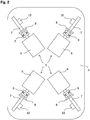
- Fig. 2 shows a preferred arrangement of exciter units 5 on a vibrating plate 4 in an arrangement of the measuring devices 8 on the imbalance shaft 7.
- the exciter units 5 are arranged in a star shape and axisymmetric to each other.
- the axes of rotation of their unbalanced shafts 7 are in diagonally arranged exciter units 5 on a straight line.
- the notionally extended axes of rotation of all unbalanced shafts 7 intersect at a point which is located approximately centrally on the vibrating plate 4.
- the excitation units 5 are individually driven by an electric drive 6 and each have a vibration exciter with an imbalance shaft. 7 and a rotating unbalance 10 and connected to the vibration exciter measuring device 8 for detecting the phase position of the imbalance shaft 7.
- the phase position of the vibration exciter is equated with the phase position of its imbalance shaft 7.
- the measuring device 8 is arranged in the direction of the action of the drive, that is, in the direction of the imbalance shaft 7 behind the elastic element 9.
- the electric drive 6 is preferably arranged in the superstructure 2, but it may also be arranged in the undercarriage 3 together with the vibration exciter on the vibration plate 4.
- Fig. 3 shows the same preferred arrangement of excitation units 5 on a vibrating plate 4 in an arrangement of the measuring devices 8 on the drive shaft of the electric drive 6.
- the only difference to Fig. 2 is the measuring device 8 in the direction of the action of the drive, that is arranged in the direction of the imbalance shaft 7, in front of the elastic element 9.
- Fig. 4 shows a schematic diagram for controlling an exciter unit 5 in an arrangement of the measuring device 8 on the drive shaft.
- the measuring device 8 is arranged in the upper carriage 2 and set up for direct detection of the phase position of the electric drive 6.
- the imbalance shaft 7 may have a slightly different phase position from this phase, the difference to the detected phase position is not constant, but which may vary in time as a function of changes in the rotational speed of the drive 6 or by the transmission of vibrations to the imbalance shaft 7. Knowing the mass ratios, the spring constant of the elastic element 9 and the time course of phase position and speed, the controller 12 can estimate the deviation of the phase position of the imbalance shaft 7 of the phase angle of the drive shaft.
- the detectable by the measuring device 8 phase position of the drive shaft can be supplied as actual phase position and feedback variable of a control loop of the control device 12.
- a manipulated variable determined by the control device 12 and a motor controller 13 can be fed.
- the motor controller 13 converts the manipulated variable into corresponding control voltages or signals for the phase or speed change of the electric drive 6.
- Fig. 5 shows a schematic diagram for controlling an excitation unit 5 in an arrangement of the measuring device 8 on the imbalance shaft 7.
- the measuring device 8 is arranged in the undercarriage 3 and set up for direct detection of the phase position of the imbalance shaft 7. This is different from Fig. 4 the actual actual phase position of the imbalance shaft 7 directly comparable to the desired phase position.
- the elastic element 9 with its time behavior ⁇ (t) is part of the controlled system. If the control device 12 is set up to generate a manipulated variable taking into account a known step response of the controlled system, and if the electric drive 6 is sufficiently fast to respond appropriately to a manipulated variable change, precise control of the phase position of the imbalance shaft 7 is achieved by compensating the time behavior ⁇ (FIG. t) of the elastic element 9 possible.
- Fig. 6 shows a schematic diagram for coupling two individual vibration exciter via one elastic element 9, 9 ', a respective electrically controllable drive 6, 6', a respective control device 12, 12 'and a higher-level control device 11;
- the vibration exciters of the exciter units 5, 5 'with individually associated control devices 12, 12' their respective desired phase position can be set as a reference variable, so that between the unbalanced shafts 7, 7 'of the vibration exciter a relative phase ⁇ is adjustable.
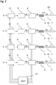
- Fig. 7 shows a block diagram for the common control of example four exciter units 5 via a control device 14.
- Wie aus Fig. 6 it can be seen that the phase positions of several measuring devices 8 are supplied together as the actual size vector of a control / regulating device 14. Due to the mechanical connection via the common vibration plate 4, the vibration exciter 5 are parasitically coupled to each other, wherein the degree of coupling additionally depends on the orientation of the vibration-generating elements of the vibration exciter 5.
- control unit 14 calculates a manipulated variable vector whose coefficients are supplied to the individual motor controllers 13.
- the calculation of the manipulated variable vector for the plurality of control loops can be optimized in such a way that high phase jumps for individual control loops are avoided, or that the magnitude of the control difference vector is minimized while maintaining the resulting motion vector.
Description
Die Erfindung betrifft ein Bodenverdichtungsgerät mit einem Oberwagen und einem Unterwagen mit einer Vibrationsplatte und einer Mehrzahl von Erregereinheiten, wobei zumindest ein Teil der Erregereinheiten von einem Antrieb jeweils individuell antreibbar ist.The invention relates to a soil compaction device with a superstructure and an undercarriage with a vibrating plate and a plurality of exciter units, wherein at least a part of the exciter units can each be driven individually by a drive.
Üblicherweise weisen Bodenverdichtungsgeräte mit einer Vibrationsplatte, wie beispielsweise eine Rüttelplatte, einen Verbrennungsmotor zum Antrieb von zwei gleichartigen, parallelen, über ein Getriebe starr gekoppelten und gegenläufigen Unwuchtwellen auf. Die gegensätzliche Rotation der mit gleicher Umdrehungszahl betriebenen Unwuchtwellen bewirkt, dass sich die durch die Unwuchten erzeugten Fliehkräfte in Abhängigkeit vom Phasenwinkel gegenseitig verstärken oder kompensieren. Durch eine geeignete Einstellung der jeweiligen Phasenlage der Unwuchten zueinander entsteht ein resultierender Kraftvektor, der zur Fortbewegung und/oder Verdichtung eingesetzt werden kann. Dabei weist eine Rüttelplatte zumeist eine Hydraulik zur Verstellung der Phasenlage der mechanisch miteinander gekoppelten Wellen auf. Häufig erfolgt dies mit Hilfe einer axial verschiebbaren Spiralwelle.Usually have Bodenverdichtungsgeräte with a vibrating plate, such as a vibrating plate, an internal combustion engine for driving two similar, parallel, rigidly coupled via a gear and counter-rotating unbalanced shafts. The opposite rotation of the unbalanced shafts operated with the same number of revolutions causes the centrifugal forces generated by the imbalances to mutually reinforce or compensate depending on the phase angle. By a suitable adjustment of the respective phase position of the imbalances to one another results in a resulting force vector, which can be used for locomotion and / or compression. In this case, a vibrating plate usually has a hydraulic system for adjusting the phase position of the mechanically coupled to each other waves. Often this is done by means of an axially displaceable spiral shaft.
Da der durch Überlagerung entstehende Kraftvektor stets senkrecht zur Rotationsachse der Unwuchtwellen orientiert ist, ist die Antriebsrichtung ohne weitere Maßnahmen auf eine Vor- und Rückwärtsfahrt beschränkt.Since the force vector resulting from superimposition is always oriented perpendicular to the axis of rotation of the imbalance shafts, the drive direction is limited to further forward and reverse travel without further measures.
Zur Verbesserung der Lenkeigenschaften ist aus der
Ferner beschreibt die
Aufgabe der vorliegenden Erfindung ist die Angabe einer kostengünstigen und zugleich zuverlässigen Lösung für ein komfortables Bodenverdichtungsgerät mit einer fein abstimmbaren und präzisen Lenkung, die eine bequeme Steuerung des Bodenverdichtungsgerätes in jede Richtung der Plattenebene erlaubt.Object of the present invention is to provide a cost-effective and reliable solution for a comfortable soil compaction device with a finely tuned and precise steering that allows easy control of the soil compaction device in each direction of the plate plane.
Die Lösung der Aufgabe erfolgt erfindungsgemäß durch die Merkmale des unabhängigen Anspruchs. Vorteilhafte Ausgestaltungen der Erfindung sind in den Unteransprüchen angegeben.The object is achieved according to the invention by the features of the independent claim. Advantageous embodiments of the invention are specified in the subclaims.
Erfindungsgemäß vorgesehen ist ein Bodenverdichtungsgerät mit einem Oberwagen und einem Unterwagen, wobei der Unterwagen eine Vibrationsplatte und eine Mehrzahl von Erregereinheiten aufweist, wobei zumindest ein Teil der Erregereinheiten von jeweils einem Antrieb jeweils individuell antreibbar ist und jeweils zumindest einen Vibrationserreger aufweist, welcher mit einer Messeinrichtung zur Erfassung seiner Phasenlage verbunden ist, wobei die Phasenlage einer Steuer-/Regeleinrichtung zuführbar ist,
und wobei einzelne Vibrationserreger jeweils über ein elastisches Element, einen jeweiligen elektrisch steuerbaren Antrieb und die Steuer-/Regeleinrichtung miteinander gekoppelt sind und die relative Phasenlage der einzelnen Vibrationserreger zueinander über die Steuer-/Regeleinrichtung einstellbar ist.According to the invention, a ground compaction device is provided with a superstructure and an undercarriage, wherein the undercarriage has a vibration plate and a plurality of excitation units, wherein at least a part of the exciter units of each drive is individually driven and each having at least one vibration exciter, which with a measuring device for Detection of its phase position is connected, wherein the phase position of a control / regulating device is fed,
and wherein individual vibration exciter are coupled to each other via an elastic element, a respective electrically controllable drive and the control / regulating device and the relative phase position of the individual vibration exciter to each other via the control / regulating device is adjustable.
Zumindest zwei der Erregereinheiten sind von jeweils einem Antrieb jeweils individuell antreibbar und weisen jeweils zumindest einen Vibrationserreger auf. Dabei kann eine Erregereinheit einen oder zwei gegenläufige, mit einander gekoppelte Vibrationserreger aufweisen. Ein Vibrationserreger kann beispielsweise aus einer Unwuchtwelle und einer rotierenden Unwucht oder einem Oszillator mit einer oszillierenden Masse bestehen. Vorteilhaft weist eine Erregereinheit genau einen Vibrationserreger mit einer Unwuchtwelle und einer rotierenden Unwucht auf.At least two of the excitation units are each individually driven by a respective drive and each have at least one vibration exciter. In this case, an exciter unit can have one or two opposite, coupled to each other vibration exciter. A vibration exciter may for example consist of an imbalance shaft and a rotating imbalance or an oscillator with an oscillating mass. Advantageously, an exciter unit has exactly one vibration exciter with an imbalance shaft and a rotating imbalance.
Weiterhin kann die Steuer-/Regeleinheit vorteilhaft aus einer übergeordneten Steuereinrichtung und mehreren von der Steuereinrichtung gesteuerten Regeleinrichtungen bestehen, wobei jeweils ein mit einer Messeinrichtung verbundener Vibrationserreger jeweils eine Regeleinrichtung aufweist und die von den jeweiligen Messeinrichtungen erfassbaren Phasenlagen den jeweiligen Regeleinrichtungen zuführbar sind. Bei dieser Ausgestaltung weist jeder Vibrationserreger einen eigenen Regelkreis zur Regelung seiner Phasenlage auf, welche der jeweiligen Regeleinrichtung als Führungsgröße vorgebbar ist. Die Phasenlage von zumindest zwei Vibrationserregern zueinander ist elektrisch veränderbar. Die Veränderung der Phasenlage zumindest eines einzelnen Vibrationserregers ist relativ zu der Phasenlage eines anderen oder weiterer Vibrationserreger durch die Änderung seiner Soll-Phasenlage als Führungsgröße änderbar. Die Soll-Phasenlage ist von der Steuerungseinrichtung, beispielsweise als Ergebnis der Umsetzung eines der Steuereinrichtung zugeführten Lenkbefehls vorgebbar.
Die Vibrationserreger sind jeweils über ein elastisches Element mit dem jeweiligen elektrischen Antrieb verbunden. Eine Abweichung einer Ist-Phasenlage von einer Soll-Phasenlage aufgrund der elastischen Verbindung ist durch die Regeleinrichtung kompensierbar. Eine Kopplung der Phasenlage zwischen zwei Vibrationserregern ist über zumindest ein elastisches Element gegeben und die Phasenlage zumindest eines der über ein elastisches Element gekoppelten Vibrationserreger ist über eine Regeleinrichtung regelbar. Eine derartige Struktur ermöglicht einen einfachen und modularen Aufbau der Steuer-/Regeleinheit.Furthermore, the control unit can advantageously consist of a higher-level control device and a plurality of control devices controlled by the control device, wherein in each case one connected to a measuring device vibration exciter each having a control device and the detectable by the respective measuring means phase positions the respective control means are supplied. In this embodiment, each vibration exciter on its own control circuit for controlling its phase position, which is the respective control device can be specified as a reference variable. The phase angle of at least two vibration exciters to each other is electrically variable. The change in the phase position of at least one individual vibration exciter can be changed relative to the phase position of another or further vibration exciter by changing its desired phase position as a reference variable. The desired phase position can be predetermined by the control device, for example as a result of the conversion of a steering command supplied to the control device.
The vibration exciters are each connected via an elastic element with the respective electric drive. A deviation of an actual phase position from a desired phase position due to the elastic connection can be compensated by the control device. A coupling of the phase position between two vibration exciters is given via at least one elastic element and the phase position of at least one of the vibration exciters coupled via an elastic element can be regulated via a regulating device. Such a structure enables a simple and modular construction of the control unit.
Mit anderen Worten ist beispielhaft ein Bodenverdichtungsgerät vorgesehen, dessen Vibrationsplatte eine Mehrzahl von elektrisch angetriebenen und elektrisch regelbaren Erregereinheiten aufweist. Dabei sind zum Beispiel die elektrischen Antriebe alle jeweils über ein elastisches Element mit den jeweiligen Vibrationserregern verbunden.In other words, by way of example, a soil compacting device is provided, the vibrating plate of which has a plurality of electrically driven and electrically controllable exciter units. In this case, for example, the electric drives are each connected in each case via an elastic element with the respective vibration exciters.
Eine derartige Anordnung weist mehrere Vorteile auf. Die Anordnung einer Mehrzahl von Erregereinheiten auf der Vibrationsplatte bietet die Möglichkeit, diese in verschiedenen Ausrichtungen anzuordnen und durch entsprechende Ansteuerung Kraftvektoren in jede Richtung zu generieren. Dabei können unterschiedliche Anzahlen baugleicher Erregereinheiten zum einen zur modularen Herstellung von Bodenverdichtungsgeräten unterschiedlicher Gewichtsklasse verwendet werden, und/oder zum anderen kann durch eine Verteilung ihrer Ausrichtungen auf der Vibrationsplatte, beispielsweise durch eine Verteilung der Ausrichtung entsprechend der Verteilung einer Intensität von Bewegungsrichtungen, eine Optimierung des Lenkungsvermögens erreicht werden.Such an arrangement has several advantages. The arrangement of a plurality of exciting units on the vibrating plate offers the possibility to arrange them in different orientations and to generate force vectors in each direction by appropriate activation. Different numbers of structurally identical exciter units can be used for the modular production of soil compactors of different weight classes, and / or on the other hand an optimization of the distribution can be achieved by distributing their orientations on the vibrating plate, for example by distributing the orientation according to the distribution of an intensity of movement directions Steering assets are achieved.
Desweiteren bietet die Verwendung elektrischer Antriebe den Vorteil, dass elektrische Zuleitungen im Vergleich zu anderen Zuleitungen wie beispielsweise Hydraulikschläuchen, eine sehr gute Dauerschwingfestigkeit aufweisen und somit verschleißfester sind.Furthermore, the use of electric drives has the advantage that electrical leads compared to other supply lines such as hydraulic hoses, have a very good fatigue life and thus are more resistant to wear.
Weiterhin bietet die Verwendung eines elastischen Elements zwischen dem Antrieb, bzw. dessen Antriebswelle und der Unwuchtwelle den Vorteil, dass es dämpfend wirkt und Schwingungen der Unwuchtwelle weniger stark auf die elektrischen Antriebe einwirken.Furthermore, the use of an elastic element between the drive, or its drive shaft and the imbalance shaft has the advantage that it acts dampening and vibrations of the imbalance shaft act less on the electric drives.
Dabei kann der gegenüber den herkömmlichen Erregern eintretende Verlust der starren Kopplung zwischen den Unwuchtwellen durch eine schnell ansprechende, präzise elektrische Regelung zumindest teilweise kompensiert werden.In this case, the loss of the rigid coupling between the imbalance shafts occurring in comparison to the conventional exciters can be at least partially compensated by a fast-response, precise electrical regulation.
Erfindungsgemäß ist dazu die Phasenlage zumindest einer der über ein elastisches Element gekoppelten Unwuchtwellen oder Oszillatoren über eine Regeleinrichtung regelbar.According to the invention, the phase position of at least one of the unbalanced shafts or oscillators coupled via an elastic element can be regulated by way of a regulating device.
Eine Erregereinheit weist eine mit dem Vibrationserreger verbundene Messeinrichtung zur Erfassung der Phasenlage des Vibrationserregers auf. Ist dieser in Form einer Unwuchtwelle ausgebildet, ist die Phasenlage von der Messeinrichtung durch die Messung des Phasenwinkels erfassbar.An excitation unit has a measuring device connected to the vibration exciter for detecting the phase position of the vibration exciter. If this is designed in the form of an imbalance wave, the phase angle of the measuring device can be detected by the measurement of the phase angle.
Die Messeinrichtung ist in der Lage, den Phasenwinkel der Unwucht im Bezug auf eine Nullstellung, beispielsweise der gravitationsbedingten Ruhestellung im Freilauf, zu erfassen und als Phasenlage an die Regeleinrichtung weiterzugeben. Die Regeleinrichtung ist eingerichtet, die Stellgrößen des Antriebs zur Erreichung einer Soll-Phasenlage einzustellen. Damit ist sie in der Lage, die Phasenlage zwischen zwei Unwuchtwellen oder Oszillatoren zu verändern, bzw. eine vorgebbare Phasenlage einzustellen. Vorteilhaft ist zumindest einem Teil der Erregereinheiten jeweils individuell eine Regeleinrichtung zugeordnet. Durch eine übergeordnete Steuereinrichtung können den individuell zugeordneten Regeleinrichtungen ihre jeweilige Soll-Phasenlage als Führungsgröße vorgegeben werdenThe measuring device is able to detect the phase angle of the unbalance with respect to a zero position, for example, the gravitational rest position in the freewheel, and pass it as a phase to the control device. The control device is set up to set the manipulated variables of the drive to achieve a desired phase position. Thus, it is able to change the phase angle between two unbalanced shafts or oscillators, or to set a predetermined phase position. Advantageously, at least a part of the exciter units each individually assigned a control device. By a higher-level control device, the individually assigned control devices can be given their respective desired phase position as a reference variable
Der Antrieb ist elektrisch ausgeführt. Ebenso weist die Messeinrichtung vorteilhaft einen Encoder zur digitalen Verarbeitung der Messwerte auf. Vorteilhaft stellt die Messeinrichtung der Regeleinrichtung neben der Phasenlage auch die Winkelgeschwindigkeit einer Welle zur Verfügung.The drive is electrically designed. Likewise, the measuring device advantageously has an encoder for the digital processing of the measured values. Advantageously, the measuring device of the control device in addition to the phase position and the angular velocity of a shaft available.
Die erfindungsgemäß vorgesehene Dämpfung der elektrischen Antriebe gegenüber der Unwuchtwelle reduziert die Anforderungen an die Belastbarkeit der elektrischen Antriebe, insbesondere ihre Vibrationsfestigkeit, und erlaubt die Verwendung vergleichsweise einfacher und preisgünstiger Komponenten.The inventively provided attenuation of the electric drives relative to the imbalance shaft reduces the demands on the capacity of the electric drives, in particular their vibration resistance, and allows the use of comparatively simple and inexpensive components.
Vorteilhaft sind die elektrischen Antriebe in dem Oberwagen angeordnet, die Vibrationserreger im Unterwagen angeordnet, und die elektrischen Antriebe im Oberwagen jeweils individuell mittels je einem elastischen Element, vorteilhaft einem Riemen, mit jeweils einem Vibrationserreger im Unterwagen verbunden. Auf diese Weise kann die Beanspruchung der elektrischen Antriebe um etwa eine Zehnerpotenz reduziert und die Lebensdauer der elektrischen Antriebe entsprechend verlängert werden.Advantageously, the electric drives are arranged in the superstructure, the vibration exciter arranged in the undercarriage, and the electric drives in the superstructure in each case individually by means of one elastic element, advantageously a belt, each connected to a vibration exciter in the undercarriage. In this way, the stress of the electric drives can be reduced by about one order of magnitude and the life of the electric drives can be extended accordingly.
Vorteilhaft weisen die Erregereinheiten genau einen Vibrationserreger mit einer einzelnen Unwuchtwelle auf. Eine derartige Ausgestaltung ist wartungsarm und kostengünstig zu realisieren.Advantageously, the exciter units have exactly one vibration exciter with a single imbalance shaft. Such a configuration is low maintenance and inexpensive to implement.
Vorteilhaft ist zumindest für einen Teil der Erregereinheiten der elektrische Antrieb als im Wesentlichen einzelner Elektromotor ausgeführt. Elektromotoren sind einfach und kostengünstig herstellbar, eine Verwendung einer Mehrzahl der gleichen Elektromotoren für die Mehrzahl der Erregereinheiten fördert durch die Verwendung gleichartiger Bauteile die Rationalisierung der Herstellung. Alternativ kann ein einzelner elektrischer Antrieb auch als elektrische Kupplung ausgebildet sein, welche ausgebildet ist, eine Antriebsenergie eines übergeordneten Antriebs partiell abzuzweigen und hinsichtlich Phasenlage und Winkelgeschwindigkeit zu individualisieren.Advantageously, at least for some of the excitation units, the electric drive is designed as a substantially individual electric motor. Electric motors are simple and inexpensive to produce, a use of a plurality of the same electric motors for the majority of excitation units promotes through the use of similar components, the rationalization of the production. Alternatively, a single electric drive can also be designed as an electrical coupling, which is designed to partially divert a drive energy of a superordinate drive and to individualize it in terms of phase position and angular velocity.
Vorteilhaft ist der elektrische Antrieb als Schrittmotor ausgeführt. Ein Schrittmotor bietet den Vorteil, dass die Winkelstellung und somit die Phasenlage der Antriebswelle einstellbar ist und somit als bekannt angenommen werden kann. Bei einer Anordnung, bei welcher die Messeinrichtung zur Erfassung der Phasenlage, in der Wirkrichtung des Antriebs gesehen, vor dem elastischen Element direkt auf der Antriebswelle angeordnet ist, kann ein Schrittmotor die Funktion der Messeinrichtung übernehmen. Die Ausführung einer Messeinrichtung als eigenständiges Bauteil kann in diesem Fall entfallen, die Messeinrichtung kann in diesem Fall als in den Schrittmotor integriert betrachtet werden. Desweiteren ist ein Schrittmotor vibrationsfest ausführbar.Advantageously, the electric drive is designed as a stepper motor. A stepper motor has the advantage that the angular position and thus the phase angle of the drive shaft is adjustable and thus can be assumed to be known. In an arrangement in which the measuring device for detecting the phase position, seen in the effective direction of the drive, is arranged directly on the drive shaft in front of the elastic element, a stepper motor can take over the function of the measuring device. The execution of a measuring device as an independent component can be omitted in this case, the measuring device can be considered in this case as integrated into the stepper motor. Furthermore, a stepper motor is vibration resistant executable.
Weiterhin vorteilhaft ist eine Regeleinrichtung als PI- oder als PID-Regler ausgebildet. Die Verbindung der Unwuchtwelle mit dem elektrischen Antrieb über ein elastisches Element führt bei einer Änderung der Winkelgeschwindigkeit zu einer Energieaufnahme des elastischen Elements, welches diese Energie zeitverzögert an die Anordnung zurückgibt. In Kenntnis der Sprungantwort der Regelstrecke, bestehend aus elektrischem Antrieb, Antriebswelle, elastischem Element und Unwuchtwelle inklusive der Unwucht, ist es möglich, den elektrischen Antrieb durch eine Regeleinrichtung derart anzusteuern, dass ein Überschwingen der Unwuchtwelle reduziert oder vermieden wird. Vorteilhaft ist eine Regeleinrichtung ausgebildet, ein Einschwingen einer Erregereinheit nach einer Phasen- oder Frequenzänderung zu minimieren.Further advantageously, a control device is designed as a PI or PID controller. The connection of the imbalance shaft with the electric drive via an elastic element leads to a change in the angular velocity to an energy absorption of the elastic element, which returns this energy with a time delay to the arrangement. In knowledge of the step response of the controlled system, consisting of electric drive, drive shaft, elastic Element and imbalance shaft including the imbalance, it is possible to control the electric drive by a control device such that overshoot of the imbalance shaft is reduced or avoided. Advantageously, a control device is designed to minimize a transient of an excitation unit after a phase or frequency change.
Die Messeinrichtung zur Erfassung der Phasenlage kann vor dem elastischen Element auf der Antriebswelle, oder hinter dem elastischen Element auf der Unwuchtwelle angeordnet sein. Eine Anordnung der Messeinrichtung auf der Unwuchtwelle eines Vibrationserregers im Unterwagen des Bodenverdichtungsgeräts bietet den Vorteil, dass einer Regeleinrichtung die tatsächliche Phasenlage und Winkelgeschwindigkeit der Unwuchtwelle zugeführt werden können.The measuring device for detecting the phase position can be arranged in front of the elastic element on the drive shaft, or behind the elastic element on the imbalance shaft. An arrangement of the measuring device on the imbalance shaft of a vibration exciter in the undercarriage of the soil compaction device offers the advantage that a control device, the actual phase angle and angular velocity of the imbalance shaft can be supplied.
Bei einer Anordnung der Messeinrichtung auf der Antriebswelle ist die Messeinrichtung nur indirekt über das elastische Element mit der Unwuchtwelle verbunden, so dass auf Grund einer Federwirkung des elastischen Elements die ermittelte Phasenlage und Winkelgeschwindigkeit geringfügig von der tatsächlichen Phasenlage und Winkelgeschwindigkeit der Unwuchtwelle abweichen kann.
In Kenntnis der Sprungantwort der Regelstrecke und der Federkonstante des elastischen Elements sowie der Masse der Unwuchtwelle kann die Abweichung zwischen der gemessenen und der tatsächlichen Phasenlage durch die Regeleinrichtung abgeschätzt werden.In an arrangement of the measuring device on the drive shaft, the measuring device is connected only indirectly via the elastic element with the imbalance shaft, so that due to a spring action of the elastic element, the determined phase angle and angular velocity may differ slightly from the actual phase angle and angular velocity of the unbalanced shaft.
Knowing the step response of the controlled system and the spring constant of the elastic element and the mass of the imbalance shaft, the deviation between the measured and the actual phase position can be estimated by the control device.
Die Drehrichtungen, Winkelgeschwindigkeiten und Phasenlagen der Vibrationserreger bilden in ihrer Überlagerung ein translatorisches und/oder rotatorisches Moment gegenüber einer Standfläche des Bodenverdichtungsgeräts. Dieses translatorische und/oder rotatorische Moment ist zur Fortbewegung und Lenkung nutzbar.The directions of rotation, angular velocities and phase positions of the vibration exciter form in their superposition a translational and / or rotational moment with respect to a standing surface of the soil compaction device. This translational and / or rotational moment can be used for locomotion and steering.
Vorteilhaft sind die Vibrationserreger winkelig, insbesondere sternförmig auf der Vibrationsplatte angeordnet. Eine symmetrische Anordnung unter gleichen Winkeln erlaubt für eine Steuereinrichtung, die beispielsweise einen Lenkbefehl in jeweilige Soll-Phasenlagen als Führungsgrößen für die jeweiligen Vibrationserreger umsetzt, eine einfache Berechnung der erforderlichen Stellwerte, um ein gewünschtes translatorisches und/oder rotatorisches Moment zu erzeugen. Dabei kann die Eingabe eines Lenkbefehls beispielsweise mittels eines in zwei Achsen beweglichen Control-Sticks als Teil einer Handsteuerung erfolgen. Weiterhin kann es sich bei der Handsteuerung um einen integrierten Bestandteil des Bodenverdichtungsgerätes oder um eine Fernsteuerung handeln.Advantageously, the vibration exciter are arranged angularly, in particular star-shaped on the vibration plate. A symmetrical arrangement at equal angles allows for a control device, for example, a steering command in respective desired phase positions as command values for the respective Vibratory exciter, a simple calculation of the required control values to produce a desired translational and / or rotational moment. In this case, the input of a steering command, for example, by means of a movable control in two axes control stick as part of a manual control. Furthermore, the hand control may be an integral part of the soil compaction device or a remote control.
Vorteilhaft ist eine Regeleinrichtung als digitaler Regler ausgebildet. Digitale Regler sind hinreichend schnell realisierbar und bieten große Flexibilität hinsichtlich ihrer Reglereigenschaften. Vorteilhaft weist eine Regeleinrichtung einen digitalen Regler auf, der für die Erzeugung der Stellgrößen für den elektrischen Antrieb einen Vorverzerrer aufweist, welcher eine derartige zeitliche Vorverzerrung der Stellgrößen bewirkt, dass ein Einschwingen in Folge einer Phasen- oder Frequenzänderung vermieden oder vermindert wird. Vorteilhaft ist die Regeleinrichtung zur Kompensation von Schwingungen eingerichtet, welche durch das elastische Element ermöglicht oder begünstigt werden.Advantageously, a control device is designed as a digital controller. Digital controllers can be implemented quickly enough and offer great flexibility in terms of their controller characteristics. Advantageously, a control device has a digital controller which has a predistorter for generating the manipulated variables for the electric drive, which causes such temporal predistortion of the manipulated variables that transient oscillation due to a phase or frequency change is avoided or reduced. Advantageously, the control device is set up to compensate for vibrations which are enabled or favored by the elastic element.
Vorteilhaft erfolgt die Vorverzerrung der Stellgrößen oder ein Einstellen der Parameter eines PI- oder PID-Reglers auf Basis der Sprungantwort der Regelstrecke. In Kenntnis der Parameter der Sprungantwort, beispielsweise deren Wendepunkt, sind die Parameter eines PI- oder PID-Reglers nach in der Literatur bekannten Einstellregeln, z.B. nach Ziegler/Nichols, dimensionierbar.Advantageously, the predistortion of the manipulated variables or setting of the parameters of a PI or PID controller based on the step response of the controlled system. Knowing the parameters of the step response, for example its inflection point, the parameters of a PI or PID controller are according to adjustment rules known in the literature, e.g. according to Ziegler / Nichols, dimensionable.
Vorteilhaft weist das Bodenverdichtungsgerät einen Kalibriermodus zum Ermitteln der Sprungantwort auf, in welchem die Sprungantwort der Regelstrecke, beispielsweise nach einem Riemenwechsel, ermittelbar ist. In einem derartigen Modus kann der Regelkreis geöffnet und die Reaktion des Vibrationserregers in Antwort auf eine Lenkbewegung respektive einer Änderung der Phasenlage des Vibrationserregers ermittelt und gespeichert werden.Advantageously, the soil compaction device has a calibration mode for determining the step response, in which the step response of the controlled system, for example after a belt change, can be determined. In such a mode, the control loop can be opened and the reaction of the vibration exciter in response to a steering movement or a change in the phase position of the vibration exciter can be determined and stored.
Weiterhin vorteilhaft ist eine Regeleinrichtung ausgebildet ist, die Messwerte mehrerer Messeinrichtungen gemeinsam auszuwerten und die Stellgrößen für die elektrischen Antriebe von mehreren Vibrationserregern derart zu optimieren, dass ein unerwünschtes Schwingen des Bodenverdichtungsgerätes vermieden oder vermindert wird.Further advantageously, a control device is designed to jointly evaluate the measured values of a plurality of measuring devices and to optimize the manipulated variables for the electric drives of a plurality of vibration exciters in such a way that undesired oscillation of the soil compacting device is avoided or reduced.
Die verschiedenen Erregereinheiten sind über die Vibrationsplatte miteinander gekoppelt, so dass sie sich gegenseitig zur Schwingung anregen, es treten Energieausgleichsvorgänge auf. Aufgrund dieser Kopplung sind auch die einzelnen Regelkreise zur Einstellung der Phasenlage nicht vollständig entkoppelt.The various excitation units are coupled together via the vibrating plate, so that they stimulate each other to vibrate, there are energy balancing operations on. Due to this coupling, the individual control circuits for adjusting the phase position are not completely decoupled.
Vorteilhaft weist das Bodenverdichtungsgerät eine Regeleinrichtung auf, die ausgebildet ist, die Phasenlagen mehrerer Messeinrichtungen gemeinsam auszuwerten und die Stellgrößen für mehrere Vibrationserreger derart zu optimieren, dass eine vom Benutzer gewünschte translatorische oder rotatorische Bewegung derart auf Phasenänderungen der Vibrationserreger umgesetzt werden, dass die Höhe der Phasensprünge minimiert wird. Dabei könnte die Optimierung beispielsweise entsprechend der Methode der minimalen Fehlerquadrate derart erfolgen, dass unter Beibehaltung des resultierenden Bewegungsvektors nicht die Regeldifferenz einzelner Regelkreise, sondern der Betrag des Regeldifferenzvektors minimiert wird. Eine derartige Optimierung ist insbesondere dann möglich, wenn eine Vielzahl von Vibrationserregern verfügbar ist und zur Ausbildung eines bestimmten gemeinsamen Kraftvektors verschiedene Auswahlen von dazu beitragenden Vibrationserregern möglich sind.Advantageously, the soil compaction device has a control device which is designed to jointly evaluate the phase positions of a plurality of vibration devices and to optimize the manipulated variables for a plurality of vibration exciters such that a translational or rotational movement desired by the user is converted to phase changes of the vibration exciters such that the height of the phase jumps is minimized. In this case, the optimization could, for example, be carried out in accordance with the method of minimum squares of the error such that, while maintaining the resulting motion vector, it is not the control difference of individual control loops that is minimized but the magnitude of the control difference vector. Such an optimization is possible in particular if a large number of vibration exciters is available and different selections of vibration exciters contributing to the formation of a specific common force vector are possible.
Nachfolgend wird die Erfindung unter Bezugnahme auf die anliegenden, schematischen Zeichnungen anhand bevorzugter Ausführungsformen näher erläutert.The invention will be explained in more detail below with reference to the attached, schematic drawings based on preferred embodiments.
Es zeigen
- Fig. 1
- eine Skizze zum Prinzip des Bodenverdichtungsgeräts;
- Fig. 2
- eine bevorzugte Anordnung von Erregereinheiten auf einer Vibrationsplatte bei einer Anordnung der Messeinrichtung auf der Unwuchtwelle;
- Fig. 3
- die bevorzugte Anordnung von Erregereinheiten bei einer Anordnung der Messeinrichtung auf der Antriebswelle;
- Fig. 4
- ein Prinzipschaltbild zur Regelung einer Erregereinheit bei einer Anordnung der Messeinrichtung auf der Antriebswelle;
- Fig. 5
- ein Prinzipschaltbild zur Regelung einer Erregereinheit bei einer Anordnung der Messeinrichtung auf der Unwuchtwelle;
- Fig. 6
- ein Prinzipschaltbild zur Kopplung zwei einzelner Vibrationserreger über jeweils ein elastisches Element, einen jeweiligen elektrisch steuerbaren Antrieb und eine elektronische Steuereinrichtung;
- Fig. 7
- ein Prinzipschaltbild zur gemeinsamen Regelung der Erregereinheiten.
- Fig. 1
- a sketch of the principle of Bodenverdichtungsgeräts;
- Fig. 2
- a preferred arrangement of exciter units on a vibrating plate in an arrangement of the measuring device on the imbalance shaft;
- Fig. 3
- the preferred arrangement of exciter units in an arrangement of the measuring device on the drive shaft;
- Fig. 4
- a schematic diagram for controlling an exciter unit in an arrangement of the measuring device on the drive shaft;
- Fig. 5
- a schematic diagram for controlling an excitation unit in an arrangement of the measuring device on the imbalance shaft;
- Fig. 6
- a schematic diagram for coupling two individual vibration exciter via a respective elastic element, a respective electrically controllable drive and an electronic control device;
- Fig. 7
- a schematic diagram for the common control of the exciter units.
Weiterhin zeigt
Die von der Messeinrichtung 8 erfassbare Phasenlage der Antriebswelle ist als Ist-Phasenlage und Rückführungsgröße eines Regelkreises der Regeleinrichtung 12 zuführbar. Unter Bestimmung der Abweichung zu einer von einer übergeordneten Steuereinrichtung 11 vorgegeben Soll-Phasenlage als Führungsgröße ist durch die Regeleinrichtung 12 eine Stellgröße bestimmbar und einer Motorsteuerung 13 zuführbar. In Abhängigkeit von der Ausgestaltung des elektrischen Antriebs 6, beispielsweise als Asynchron- oder als Schrittmotor, setzt die Motorsteuerung 13 die Stellgröße in entsprechende Steuerspannungen oder -signale zur Phasen- oder Drehzahländerung des elektrischen Antriebs 6 um.The detectable by the measuring
Die Steuer-/Regeleinrichtung 14 berechnet unter Berücksichtigung der Koppelungen der Regelkreise einen Stellgrößenvektor, dessen Koeffizienten den einzelnen Motorsteuerungen 13 zugeführt werden.Taking into account the couplings of the control circuits, the
Dabei kann die Berechnung des Stellgrößenvektors für die mehreren Regelkreise derart optimiert werden, dass hohe Phasensprünge für einzelne Regelkreise vermieden werden, bzw. dass unter Beibehaltung des resultierenden Bewegungsvektors eine Minimierung des Betrags des Regeldifferenzvektors erfolgt.In this case, the calculation of the manipulated variable vector for the plurality of control loops can be optimized in such a way that high phase jumps for individual control loops are avoided, or that the magnitude of the control difference vector is minimized while maintaining the resulting motion vector.
Claims (14)
- A soil compaction machine (1) comprising an upper carriage (2) and an undercarriage (3), wherein the undercarriage (2) comprises a vibratory plate (4) and a plurality of excitation units (5), wherein at least some of said excitation units (5) can each be individually driven by a respective drive (6), and each has at least one vibration exciter that is connected to a measuring means (8) for detecting the phase position of said exciter, wherein the phase position is able to be conveyed to a control/regulating means (14),
characterised in that
the individual vibration exciters are each coupled together via an elastic member (9), an electrically controllable drive (6) and the control/regulating means (14), and the relative phase position of the individual vibration exciters with respect to one another is adjustable by way of the control/regulating means (14). - The soil compaction machine (1) according to claim 1, characterised in that the control/regulating means (14) comprises a superordinate control means (11) and a plurality of regulating means (12) controlled by said control means (11), wherein each vibration exciter that is connected to a measuring means (8) is associated with a respective regulating means (11), and the relevant phase positions detectable by the respective measuring means (8) are able to be conveyed to each of the regulating means (11).
- The soil compaction machine (1) according to claim 1 or claim 2, characterised in that at least some of said excitation units (5) can each be individually and electrically driven by a drive (6), and the control/regulating means (14) or a regulating means (12) is designed to minimise overshoot in an excitation unit (5) following a phase or frequency change.
- The soil compaction machine (1) according to any of the preceding claims, characterised in that the undercarriage (3) is elastically connected to the upper carriage (2), the upper carriage (2) comprises a plurality of electrical drives (6), and the vibration exciters on the undercarriage (3) are each connected to one of the electric drives (6) via an elastic member (9).
- The soil compaction machine (1) according to any of the preceding claims, characterised in that the vibration exciters comprise a single eccentric shaft (7).
- The soil compaction machine (1) according to any of the preceding claims, characterised in that, in at least some of the excitation units (5), the electric drive (6) is in each case essentially designed by way of an electric motor, in particular a stepper motor, the elastic member (9) is in each case designed as a belt, the vibration exciter in each case comprises an eccentric shaft (7), and the measuring means (8) is in each case arranged on the undercarriage (3).
- The soil compaction machine (1) according to any of the preceding claims, characterised in that the vibration exciters are arranged on the vibratory plate (4) at angles, in particular in the shape of a star, and that, by way of a control means (11), the directions of rotation, angular velocities, and phase positions of the vibration exciters are, by way of superposition, adjustable in a way that generates a translational and/or rotational torque with respect to a footprint of the soil compaction machine (1).
- The soil compaction machine (1) according to any of claims 2 to 7, characterised in that at least some of the vibration exciters are each associated with a regulating means (12).
- The soil compaction machine (1) according to any of the preceding claims, characterised in that the control/regulating means (14) or a regulating means (12) is designed as a PI controller or a PID controller.
- The soil compaction machine (1) according to any of the preceding claims, characterised in that the control/regulating means (14) or a regulating means (12) is designed as a digital controller, and the regulating means (12, 14) comprises a predistorter used to generate manipulated variables for the electric drive (6), said distorter causing time-related predistortion of the manipulated variables so as to prevent or minimise overshoot resulting from a phase or frequency change.
- The soil compaction machine (1) according to claim 10, characterised in that said predistortion takes place on the basis of the step response in the regulation circuit.
- The soil compaction machine (1) according to claim 11, characterised in that the soil compaction machine (1) has a calibration mode in which the step response in the regulation circuit is able to be determined by the soil compaction machine (1), in particular following replacement of the elastic member (9).
- The soil compaction machine (1) according to any of the preceding claims, characterised in that the control/regulating means (14) is designed to collectively evaluate the values measured by a plurality of measuring means (8) and to optimise the manipulated variables for the electric drives (6) of a plurality of vibration exciters in a way that prevents or minimises undesired oscillation of the soil compaction machine (1).
- The soil compaction machine (1) according to any of the preceding claims, characterised in that the control/regulating means (14) is designed to collectively evaluate the values measured by a plurality of measuring means (8) and to optimise the manipulated variables for a plurality of vibration exciters, with the result that translational or rotational motion desired by the operator is converted into phase changes of the vibration exciters in a way that minimises the intensity of phase jumps.
Priority Applications (1)
| Application Number | Priority Date | Filing Date | Title |
|---|---|---|---|
| PL18170921T PL3399105T3 (en) | 2017-05-05 | 2018-05-04 | Soil compaction device |
Applications Claiming Priority (1)
| Application Number | Priority Date | Filing Date | Title |
|---|---|---|---|
| DE102017109686.8A DE102017109686B4 (en) | 2017-05-05 | 2017-05-05 | Soil Compactor |
Publications (2)
| Publication Number | Publication Date |
|---|---|
| EP3399105A1 EP3399105A1 (en) | 2018-11-07 |
| EP3399105B1 true EP3399105B1 (en) | 2019-05-22 |
Family
ID=62116764
Family Applications (1)
| Application Number | Title | Priority Date | Filing Date |
|---|---|---|---|
| EP18170921.3A Active EP3399105B1 (en) | 2017-05-05 | 2018-05-04 | Soil compaction device |
Country Status (3)
| Country | Link |
|---|---|
| EP (1) | EP3399105B1 (en) |
| DE (1) | DE102017109686B4 (en) |
| PL (1) | PL3399105T3 (en) |
Family Cites Families (9)
| Publication number | Priority date | Publication date | Assignee | Title |
|---|---|---|---|---|
| GB805643A (en) * | 1955-04-09 | 1958-12-10 | Losenhausenwerk Duesseldorfer | Road tamper |
| AT225222B (en) * | 1959-01-16 | 1963-01-10 | Losenhausenwerk Duesseldorfer | Method and device for soil compaction by means of vibratory vibrations |
| US5149225A (en) * | 1991-03-13 | 1992-09-22 | M-B-W Inc. | Reversible drive for a vibratory compactor |
| DE19511608A1 (en) * | 1995-03-30 | 1996-10-10 | Zenith Maschf Gmbh | Vibrating device for the vibrating table of a stone molding machine |
| DE10053446B4 (en) * | 2000-10-27 | 2006-03-02 | Wacker Construction Equipment Ag | Steerable vibration plate and mobile vibrating plate system |
| US7354221B2 (en) * | 2005-02-28 | 2008-04-08 | Caterpillar Inc. | Self-propelled plate compactor having linear excitation |
| DE102005029434A1 (en) * | 2005-06-24 | 2006-12-28 | Wacker Construction Equipment Ag | Vibrating plate with individually adjustable vibration generators comprising individual exciters each with unbalanced shaft whose rotational speed and/or phase position can be individually controlled |
| DE102005029433A1 (en) * | 2005-06-24 | 2006-12-28 | Wacker Construction Equipment Ag | Vibrating plate for compacting soil has one unbalanced mass not requiring phase adjusting device but all other unbalanced masses with such device |
| DE202010017338U1 (en) * | 2010-05-03 | 2012-01-04 | Wacker Neuson Se | Measuring device for determining floor characteristics |
-
2017
- 2017-05-05 DE DE102017109686.8A patent/DE102017109686B4/en not_active Expired - Fee Related
-
2018
- 2018-05-04 EP EP18170921.3A patent/EP3399105B1/en active Active
- 2018-05-04 PL PL18170921T patent/PL3399105T3/en unknown
Non-Patent Citations (1)
| Title |
|---|
| None * |
Also Published As
| Publication number | Publication date |
|---|---|
| DE102017109686B4 (en) | 2019-08-29 |
| DE102017109686A1 (en) | 2018-11-08 |
| EP3399105A1 (en) | 2018-11-07 |
| PL3399105T3 (en) | 2019-11-29 |
Similar Documents
| Publication | Publication Date | Title |
|---|---|---|
| EP3902637B1 (en) | Device and method for setting and controlling at least one oscillation mode by means of the plurality of unbalance exciter units on a screening device | |
| DE102019214864B3 (en) | Method and device for controlling and regulating a screening device and use | |
| DE4116647C5 (en) | shaker | |
| EP2910312A1 (en) | Pivoting assembly for a vibrating table or a screening device | |
| EP3992364A1 (en) | Method for compacting asphalt material | |
| EP3789126A1 (en) | Adjustable screening machine | |
| EP3399105B1 (en) | Soil compaction device | |
| DE10301143A1 (en) | Method and device for adjusting the amount of bulk material on a conveyor trough of a vibrating machine | |
| DE102004014750A1 (en) | Soil compacting device | |
| EP2363212A2 (en) | Infinitely adjustable oscillation exciter | |
| EP2737228A2 (en) | Device and set of devices for monitoring mechanical oscillations | |
| EP3693090A1 (en) | Adjustable screening machine and method for operating an adjustable screening machine | |
| EP2392413A2 (en) | Vibration ram | |
| EP1534439B1 (en) | Vibration exciter for soil compacting devices | |
| WO2017076525A1 (en) | Vibration generator and method for driving a pile into a soil | |
| EP3004685B1 (en) | Method for operating screening machines comprising moving screens and arranged on a common floor | |
| DE1117504B (en) | Unbalance device for compacting the soil | |
| DE202016005517U1 (en) | Devices and systems with elastic unbalance drive for modifying vibration states | |
| DE102021121614B3 (en) | Conveyor system and method for conveying bulk material | |
| BE1030008B1 (en) | Vibrating conveyor with imbalance exciter units arranged in clusters | |
| DE102022100143B4 (en) | Vibrating machine and method for operating a vibrating machine | |
| EP1214988B1 (en) | Device for producing pipes from a compactable material | |
| DE1997933U (en) | VIBRATION DEVICE | |
| WO2023194512A1 (en) | Vibratory machine and method for operating the vibratory machine | |
| WO2018141601A1 (en) | Vibration producer and method for producing vibrations |
Legal Events
| Date | Code | Title | Description |
|---|---|---|---|
| PUAI | Public reference made under article 153(3) epc to a published international application that has entered the european phase |
Free format text: ORIGINAL CODE: 0009012 |
|
| STAA | Information on the status of an ep patent application or granted ep patent |
Free format text: STATUS: REQUEST FOR EXAMINATION WAS MADE |
|
| 17P | Request for examination filed |
Effective date: 20180730 |
|
| AK | Designated contracting states |
Kind code of ref document: A1 Designated state(s): AL AT BE BG CH CY CZ DE DK EE ES FI FR GB GR HR HU IE IS IT LI LT LU LV MC MK MT NL NO PL PT RO RS SE SI SK SM TR |
|
| AX | Request for extension of the european patent |
Extension state: BA ME |
|
| GRAP | Despatch of communication of intention to grant a patent |
Free format text: ORIGINAL CODE: EPIDOSNIGR1 |
|
| STAA | Information on the status of an ep patent application or granted ep patent |
Free format text: STATUS: GRANT OF PATENT IS INTENDED |
|
| INTG | Intention to grant announced |
Effective date: 20181203 |
|
| GRAS | Grant fee paid |
Free format text: ORIGINAL CODE: EPIDOSNIGR3 |
|
| GRAA | (expected) grant |
Free format text: ORIGINAL CODE: 0009210 |
|
| STAA | Information on the status of an ep patent application or granted ep patent |
Free format text: STATUS: THE PATENT HAS BEEN GRANTED |
|
| AK | Designated contracting states |
Kind code of ref document: B1 Designated state(s): AL AT BE BG CH CY CZ DE DK EE ES FI FR GB GR HR HU IE IS IT LI LT LU LV MC MK MT NL NO PL PT RO RS SE SI SK SM TR |
|
| REG | Reference to a national code |
Ref country code: GB Ref legal event code: FG4D Free format text: NOT ENGLISH |
|
| REG | Reference to a national code |
Ref country code: CH Ref legal event code: EP |
|
| REG | Reference to a national code |
Ref country code: IE Ref legal event code: FG4D Free format text: LANGUAGE OF EP DOCUMENT: GERMAN |
|
| REG | Reference to a national code |
Ref country code: DE Ref legal event code: R096 Ref document number: 502018000037 Country of ref document: DE |
|
| REG | Reference to a national code |
Ref country code: AT Ref legal event code: REF Ref document number: 1136271 Country of ref document: AT Kind code of ref document: T Effective date: 20190615 |
|
| REG | Reference to a national code |
Ref country code: CH Ref legal event code: NV Representative=s name: TR-IP CONSULTING LLC, CH |
|
| REG | Reference to a national code |
Ref country code: NO Ref legal event code: T2 Effective date: 20190522 |
|
| REG | Reference to a national code |
Ref country code: NL Ref legal event code: FP |
|
| REG | Reference to a national code |
Ref country code: SE Ref legal event code: TRGR |
|
| REG | Reference to a national code |
Ref country code: LT Ref legal event code: MG4D |
|
| PG25 | Lapsed in a contracting state [announced via postgrant information from national office to epo] |
Ref country code: LT Free format text: LAPSE BECAUSE OF FAILURE TO SUBMIT A TRANSLATION OF THE DESCRIPTION OR TO PAY THE FEE WITHIN THE PRESCRIBED TIME-LIMIT Effective date: 20190522 Ref country code: AL Free format text: LAPSE BECAUSE OF FAILURE TO SUBMIT A TRANSLATION OF THE DESCRIPTION OR TO PAY THE FEE WITHIN THE PRESCRIBED TIME-LIMIT Effective date: 20190522 Ref country code: PT Free format text: LAPSE BECAUSE OF FAILURE TO SUBMIT A TRANSLATION OF THE DESCRIPTION OR TO PAY THE FEE WITHIN THE PRESCRIBED TIME-LIMIT Effective date: 20190922 Ref country code: FI Free format text: LAPSE BECAUSE OF FAILURE TO SUBMIT A TRANSLATION OF THE DESCRIPTION OR TO PAY THE FEE WITHIN THE PRESCRIBED TIME-LIMIT Effective date: 20190522 Ref country code: ES Free format text: LAPSE BECAUSE OF FAILURE TO SUBMIT A TRANSLATION OF THE DESCRIPTION OR TO PAY THE FEE WITHIN THE PRESCRIBED TIME-LIMIT Effective date: 20190522 Ref country code: HR Free format text: LAPSE BECAUSE OF FAILURE TO SUBMIT A TRANSLATION OF THE DESCRIPTION OR TO PAY THE FEE WITHIN THE PRESCRIBED TIME-LIMIT Effective date: 20190522 |
|
| PG25 | Lapsed in a contracting state [announced via postgrant information from national office to epo] |
Ref country code: BG Free format text: LAPSE BECAUSE OF FAILURE TO SUBMIT A TRANSLATION OF THE DESCRIPTION OR TO PAY THE FEE WITHIN THE PRESCRIBED TIME-LIMIT Effective date: 20190822 Ref country code: GR Free format text: LAPSE BECAUSE OF FAILURE TO SUBMIT A TRANSLATION OF THE DESCRIPTION OR TO PAY THE FEE WITHIN THE PRESCRIBED TIME-LIMIT Effective date: 20190823 Ref country code: RS Free format text: LAPSE BECAUSE OF FAILURE TO SUBMIT A TRANSLATION OF THE DESCRIPTION OR TO PAY THE FEE WITHIN THE PRESCRIBED TIME-LIMIT Effective date: 20190522 Ref country code: LV Free format text: LAPSE BECAUSE OF FAILURE TO SUBMIT A TRANSLATION OF THE DESCRIPTION OR TO PAY THE FEE WITHIN THE PRESCRIBED TIME-LIMIT Effective date: 20190522 |
|
| PG25 | Lapsed in a contracting state [announced via postgrant information from national office to epo] |
Ref country code: EE Free format text: LAPSE BECAUSE OF FAILURE TO SUBMIT A TRANSLATION OF THE DESCRIPTION OR TO PAY THE FEE WITHIN THE PRESCRIBED TIME-LIMIT Effective date: 20190522 Ref country code: DK Free format text: LAPSE BECAUSE OF FAILURE TO SUBMIT A TRANSLATION OF THE DESCRIPTION OR TO PAY THE FEE WITHIN THE PRESCRIBED TIME-LIMIT Effective date: 20190522 Ref country code: SK Free format text: LAPSE BECAUSE OF FAILURE TO SUBMIT A TRANSLATION OF THE DESCRIPTION OR TO PAY THE FEE WITHIN THE PRESCRIBED TIME-LIMIT Effective date: 20190522 Ref country code: RO Free format text: LAPSE BECAUSE OF FAILURE TO SUBMIT A TRANSLATION OF THE DESCRIPTION OR TO PAY THE FEE WITHIN THE PRESCRIBED TIME-LIMIT Effective date: 20190522 Ref country code: CZ Free format text: LAPSE BECAUSE OF FAILURE TO SUBMIT A TRANSLATION OF THE DESCRIPTION OR TO PAY THE FEE WITHIN THE PRESCRIBED TIME-LIMIT Effective date: 20190522 |
|
| REG | Reference to a national code |
Ref country code: CH Ref legal event code: PCAR Free format text: NEW ADDRESS: ROUTE DU COUTSET 18, 1485 NUVILLY (CH) |
|
| REG | Reference to a national code |
Ref country code: DE Ref legal event code: R097 Ref document number: 502018000037 Country of ref document: DE |
|
| PG25 | Lapsed in a contracting state [announced via postgrant information from national office to epo] |
Ref country code: SM Free format text: LAPSE BECAUSE OF FAILURE TO SUBMIT A TRANSLATION OF THE DESCRIPTION OR TO PAY THE FEE WITHIN THE PRESCRIBED TIME-LIMIT Effective date: 20190522 |
|
| PLBE | No opposition filed within time limit |
Free format text: ORIGINAL CODE: 0009261 |
|
| STAA | Information on the status of an ep patent application or granted ep patent |
Free format text: STATUS: NO OPPOSITION FILED WITHIN TIME LIMIT |
|
| PG25 | Lapsed in a contracting state [announced via postgrant information from national office to epo] |
Ref country code: TR Free format text: LAPSE BECAUSE OF FAILURE TO SUBMIT A TRANSLATION OF THE DESCRIPTION OR TO PAY THE FEE WITHIN THE PRESCRIBED TIME-LIMIT Effective date: 20190522 |
|
| 26N | No opposition filed |
Effective date: 20200225 |
|
| PGFP | Annual fee paid to national office [announced via postgrant information from national office to epo] |
Ref country code: IE Payment date: 20200825 Year of fee payment: 3 |
|
| PG25 | Lapsed in a contracting state [announced via postgrant information from national office to epo] |
Ref country code: MC Free format text: LAPSE BECAUSE OF FAILURE TO SUBMIT A TRANSLATION OF THE DESCRIPTION OR TO PAY THE FEE WITHIN THE PRESCRIBED TIME-LIMIT Effective date: 20190522 |
|
| PG25 | Lapsed in a contracting state [announced via postgrant information from national office to epo] |
Ref country code: LU Free format text: LAPSE BECAUSE OF NON-PAYMENT OF DUE FEES Effective date: 20200504 |
|
| PG25 | Lapsed in a contracting state [announced via postgrant information from national office to epo] |
Ref country code: IE Free format text: LAPSE BECAUSE OF NON-PAYMENT OF DUE FEES Effective date: 20210504 |
|
| PG25 | Lapsed in a contracting state [announced via postgrant information from national office to epo] |
Ref country code: MT Free format text: LAPSE BECAUSE OF FAILURE TO SUBMIT A TRANSLATION OF THE DESCRIPTION OR TO PAY THE FEE WITHIN THE PRESCRIBED TIME-LIMIT Effective date: 20190522 Ref country code: CY Free format text: LAPSE BECAUSE OF FAILURE TO SUBMIT A TRANSLATION OF THE DESCRIPTION OR TO PAY THE FEE WITHIN THE PRESCRIBED TIME-LIMIT Effective date: 20190522 |
|
| PG25 | Lapsed in a contracting state [announced via postgrant information from national office to epo] |
Ref country code: MK Free format text: LAPSE BECAUSE OF FAILURE TO SUBMIT A TRANSLATION OF THE DESCRIPTION OR TO PAY THE FEE WITHIN THE PRESCRIBED TIME-LIMIT Effective date: 20190522 Ref country code: IS Free format text: LAPSE BECAUSE OF FAILURE TO SUBMIT A TRANSLATION OF THE DESCRIPTION OR TO PAY THE FEE WITHIN THE PRESCRIBED TIME-LIMIT Effective date: 20190922 |
|
| PGFP | Annual fee paid to national office [announced via postgrant information from national office to epo] |
Ref country code: NO Payment date: 20230511 Year of fee payment: 6 Ref country code: NL Payment date: 20230512 Year of fee payment: 6 Ref country code: IT Payment date: 20230512 Year of fee payment: 6 Ref country code: FR Payment date: 20230419 Year of fee payment: 6 Ref country code: DE Payment date: 20230512 Year of fee payment: 6 Ref country code: CH Payment date: 20230602 Year of fee payment: 6 |
|
| PGFP | Annual fee paid to national office [announced via postgrant information from national office to epo] |
Ref country code: SE Payment date: 20230510 Year of fee payment: 6 Ref country code: PL Payment date: 20230419 Year of fee payment: 6 Ref country code: AT Payment date: 20230512 Year of fee payment: 6 |
|
| PG25 | Lapsed in a contracting state [announced via postgrant information from national office to epo] |
Ref country code: SI Free format text: LAPSE BECAUSE OF FAILURE TO SUBMIT A TRANSLATION OF THE DESCRIPTION OR TO PAY THE FEE WITHIN THE PRESCRIBED TIME-LIMIT Effective date: 20190522 |
|
| PGFP | Annual fee paid to national office [announced via postgrant information from national office to epo] |
Ref country code: BE Payment date: 20230512 Year of fee payment: 6 |
|
| PGFP | Annual fee paid to national office [announced via postgrant information from national office to epo] |
Ref country code: GB Payment date: 20230426 Year of fee payment: 6 |