EP3398711B1 - Werkzeugmaschine mit modularer roboter-beladezelle - Google Patents
Werkzeugmaschine mit modularer roboter-beladezelle Download PDFInfo
- Publication number
- EP3398711B1 EP3398711B1 EP17169245.2A EP17169245A EP3398711B1 EP 3398711 B1 EP3398711 B1 EP 3398711B1 EP 17169245 A EP17169245 A EP 17169245A EP 3398711 B1 EP3398711 B1 EP 3398711B1
- Authority
- EP
- European Patent Office
- Prior art keywords
- cell
- machine tool
- tool according
- machine
- loading
- Prior art date
- Legal status (The legal status is an assumption and is not a legal conclusion. Google has not performed a legal analysis and makes no representation as to the accuracy of the status listed.)
- Active
Links
Images

Classifications
-
- B—PERFORMING OPERATIONS; TRANSPORTING
- B23—MACHINE TOOLS; METAL-WORKING NOT OTHERWISE PROVIDED FOR
- B23Q—DETAILS, COMPONENTS, OR ACCESSORIES FOR MACHINE TOOLS, e.g. ARRANGEMENTS FOR COPYING OR CONTROLLING; MACHINE TOOLS IN GENERAL CHARACTERISED BY THE CONSTRUCTION OF PARTICULAR DETAILS OR COMPONENTS; COMBINATIONS OR ASSOCIATIONS OF METAL-WORKING MACHINES, NOT DIRECTED TO A PARTICULAR RESULT
- B23Q7/00—Arrangements for handling work specially combined with or arranged in, or specially adapted for use in connection with, machine tools, e.g. for conveying, loading, positioning, discharging, sorting
-
- B—PERFORMING OPERATIONS; TRANSPORTING
- B23—MACHINE TOOLS; METAL-WORKING NOT OTHERWISE PROVIDED FOR
- B23Q—DETAILS, COMPONENTS, OR ACCESSORIES FOR MACHINE TOOLS, e.g. ARRANGEMENTS FOR COPYING OR CONTROLLING; MACHINE TOOLS IN GENERAL CHARACTERISED BY THE CONSTRUCTION OF PARTICULAR DETAILS OR COMPONENTS; COMBINATIONS OR ASSOCIATIONS OF METAL-WORKING MACHINES, NOT DIRECTED TO A PARTICULAR RESULT
- B23Q1/00—Members which are comprised in the general build-up of a form of machine, particularly relatively large fixed members
- B23Q1/01—Frames, beds, pillars or like members; Arrangement of ways
- B23Q1/015—Frames, beds, pillars
-
- B—PERFORMING OPERATIONS; TRANSPORTING
- B23—MACHINE TOOLS; METAL-WORKING NOT OTHERWISE PROVIDED FOR
- B23Q—DETAILS, COMPONENTS, OR ACCESSORIES FOR MACHINE TOOLS, e.g. ARRANGEMENTS FOR COPYING OR CONTROLLING; MACHINE TOOLS IN GENERAL CHARACTERISED BY THE CONSTRUCTION OF PARTICULAR DETAILS OR COMPONENTS; COMBINATIONS OR ASSOCIATIONS OF METAL-WORKING MACHINES, NOT DIRECTED TO A PARTICULAR RESULT
- B23Q1/00—Members which are comprised in the general build-up of a form of machine, particularly relatively large fixed members
- B23Q1/01—Frames, beds, pillars or like members; Arrangement of ways
-
- B—PERFORMING OPERATIONS; TRANSPORTING
- B23—MACHINE TOOLS; METAL-WORKING NOT OTHERWISE PROVIDED FOR
- B23Q—DETAILS, COMPONENTS, OR ACCESSORIES FOR MACHINE TOOLS, e.g. ARRANGEMENTS FOR COPYING OR CONTROLLING; MACHINE TOOLS IN GENERAL CHARACTERISED BY THE CONSTRUCTION OF PARTICULAR DETAILS OR COMPONENTS; COMBINATIONS OR ASSOCIATIONS OF METAL-WORKING MACHINES, NOT DIRECTED TO A PARTICULAR RESULT
- B23Q11/00—Accessories fitted to machine tools for keeping tools or parts of the machine in good working condition or for cooling work; Safety devices specially combined with or arranged in, or specially adapted for use in connection with, machine tools
- B23Q11/08—Protective coverings for parts of machine tools; Splash guards
-
- B—PERFORMING OPERATIONS; TRANSPORTING
- B23—MACHINE TOOLS; METAL-WORKING NOT OTHERWISE PROVIDED FOR
- B23Q—DETAILS, COMPONENTS, OR ACCESSORIES FOR MACHINE TOOLS, e.g. ARRANGEMENTS FOR COPYING OR CONTROLLING; MACHINE TOOLS IN GENERAL CHARACTERISED BY THE CONSTRUCTION OF PARTICULAR DETAILS OR COMPONENTS; COMBINATIONS OR ASSOCIATIONS OF METAL-WORKING MACHINES, NOT DIRECTED TO A PARTICULAR RESULT
- B23Q7/00—Arrangements for handling work specially combined with or arranged in, or specially adapted for use in connection with, machine tools, e.g. for conveying, loading, positioning, discharging, sorting
- B23Q7/04—Arrangements for handling work specially combined with or arranged in, or specially adapted for use in connection with, machine tools, e.g. for conveying, loading, positioning, discharging, sorting by means of grippers
-
- B—PERFORMING OPERATIONS; TRANSPORTING
- B25—HAND TOOLS; PORTABLE POWER-DRIVEN TOOLS; MANIPULATORS
- B25J—MANIPULATORS; CHAMBERS PROVIDED WITH MANIPULATION DEVICES
- B25J21/00—Chambers provided with manipulation devices
-
- B—PERFORMING OPERATIONS; TRANSPORTING
- B25—HAND TOOLS; PORTABLE POWER-DRIVEN TOOLS; MANIPULATORS
- B25J—MANIPULATORS; CHAMBERS PROVIDED WITH MANIPULATION DEVICES
- B25J9/00—Program-controlled manipulators
- B25J9/0009—Constructional details, e.g. manipulator supports, bases
- B25J9/0018—Bases fixed on ceiling, i.e. upside down manipulators
Definitions
- the invention relates to a machine tool for the particular machining of workpieces, comprising a rotatably mounted on a machine frame work table, in particular double pivot support for workpieces to be machined and held on a machine frame, in particular horizontal tool spindle with a tool for machining workpieces.
- a double swivel table is mounted about a horizontal axis, whose one swivel table as the processing side and the other swivel table as assembly side by swiveling the double swivel table are interchangeable.
- a partition wall is provided which separates the machining side and the mounting side, and a suction device is connected to the machining side via at least one chip screen.
- the partition wall has a chamber with a lateral chip screen and an outwardly open opening, which is connected in the one pivot end position of the double pivot table with the suction device.
- a nozzle of a blowing and / or rinsing device is directed on the inside to the swarf screen.
- a placement robot which either stands on the machine bed or is flanged on the front side to a machine side.
- machine components located in the machine interior such as pull-out drawers of a workpiece store, are obstacles about which the placement robot has to pivot.
- a robot for loading the workpiece table with workpieces to be machined and for unloading the workpiece table of machined workpieces in a loading cell, which is laterally coupled to the machine frame, is suspended, that the loading cell to a vertical axis between an open and a closed position pivotable cell door, in particular circular door, which closes the cell interior in the closed position and releases in the open position, and that the cell door has a particular circular sector door bottom, which protrudes at least in the closed position below the robot into the cell interior.
- the robot is held suspended from the cell ceiling of the loading cell.
- an autonomous robot loading cell for docking to a substantially unchanged basic machine, wherein machine components located in the interior of the machine are not an obstacle for the hanging-down robot, which enables simple and fast robot movements.
- the loading cell also offers space for additional technologies, such as Labeling, re-clamping, reversing, cleaning, drying, measuring of workpieces or additional machining tasks such. Deburring of workpieces.
- the fully automatic loading and unloading of workpieces by means of the robot takes place behind the closed cell door, while the robot setting, the manual loading and unloading of workpieces as well as the workpiece reworking are carried out by the machine operator with the cell door open.
- the cell door has an in particular circular sector-shaped Tuerber réelle, which is arranged at least in the closed position above the robot.
- the door bottom on a slope so that dripping from workpieces dripping water can flow directed.
- the cell door may be down to the floor level of the machine frame or, preferably, only about half the height of a machine operator standing in front of the machine frame réellecken.
- the loading cell can have at least one fastening surface, in particular a lower and an upper fastening surface, with which the loading cell is fastened to corresponding counter-fastening surfaces of the machine frame.
- a damping layer is preferably arranged between a fastening surface of the loading cell and the counter-fastening surface of the machine frame, which is e.g. can be designed as an elastomer or metal foam.
- the loading cell has a sloping cell bottom, which is connected to a drain of the machine frame.
- the drainage connection is formed by mutually communicating openings, which respectively open into adjoining interface surfaces of the loading cell and of the machine frame.
- the loading cell is preferably arranged between the machine frame on the one hand and a workpiece store or conveyor on the other hand.
- the workpiece storage or conveyor is preferably coupled to the loading cell above the corner.
- This corner solution is the material flow, ie the workpiece supply and removal, transversely to the machine frame or parallel to the horizontal axis of rotation of the workpiece table, the access to the cell interior via corner by means of the circular door.
- corner solutions thus require little more gross floor space despite additional automatic workpiece supply and removal.
- a workpiece table in the form of a double swivel table (double pivot bar) is pivotally supported 4 in the frame-like machine frame 2 about a horizontal axis 3 whose one rotating worktable 4a (in Fig. 1 the right) on the processing side 5 within a processing space and the other pivot table 4b (in Fig. 1 the left) are provided on the loading or component side 6 within a placement space.
- pivoting (double arrow 7 ) of the double pivoting table 4 about the horizontal axis 3 by 180 ° the machining-side pivoting table 4a and the stock-side tilting table 4b can be reversed.
- the two pivoting tables 4a, 4b are mounted between and on two swashplates 8, which are mounted laterally on the machine frame 2 about the horizontal axis 3, each about a horizontal pivot axis (A-axis) 9 pivotally mounted (double arrow 10 ).
- the processing and assembly rooms are either each self-contained machine rooms or together form a self-contained engine room.
- the double swivel table 4 is rotatably mounted on two opposite side walls 11 of the machine frame 2, which are connected together below by a bottom support 12 and above by a ceiling support 13 and, for example, together with the bottom and the ceiling beams 12, 13 a monobloc frame form.
- the stock-side swivel table 4b is equipped with workpieces 14 to be machined, which are then machined after interchanging the swivel tables 4a, 4b on the machining side 5 by means of a tool 16 received in a horizontal work spindle 15 .
- the horizontal work spindle 15 is by means of an XYZ carriage unit 17 to the one, in Fig. 1 attached to the right end sides of the side walls 11.
- To swap the swivel tables 4a, 4b of the double swivel table 4 is pivoted in the pivoting direction 7 by 180 °, which is reversed with swivel tables 4a, 4b again in Fig. 1 shown arrangement results.
- one or both swivel tables 4a, 4b can also be pivoted about their pivot axes 9 are pivoted in the pivoting direction 10.
- a fixed splash guard wall 18 is fixed, which in the in Fig. 1 shown Schwenkendposition of the double swing table 4, the processing and assembly sides 5, 6 separated from each other. In this way, a new workpiece 14 can be clamped on the component side during the processing of the workpieces 14 on the machining side 5, wherein the operator is protected from splashing drilling water or flying chips, etc.
- a load cell 20 is coupled (flanged) to the machine frame 2, in the cell interior 21 a (gripping) robot 22 for automatically loading the stock-side swivel table 4b to be machined workpieces 14 and for automatically unloading the stock-side swivel table 4b of machined workpieces 14 is suspended from a cell ceiling 23 is mounted.
- the gripping robot 22 has at least five axes of rotation and, as in the exemplary embodiment shown, can be designed with two articulated arms and one gripper.
- the loading cell 20 has a lower and an upper, lateral attachment surface (flange surface) 24 , with which the loading cell 20 is attached to corresponding, lateral Jacobbefest Trents vom 25 of the bottom and the ceiling support 12, 13.
- a respective damping layer 26 is arranged to decouple the machine frame 2 and the loading cell 20 from each other with respect to vibrations.
- the loading cell 20 further has for drilling water discharge a cell bottom 27 with a slope in the direction of an opening 28 , which is present in the lower mounting surface 24.
- the machine frame 2 in turn, has a corresponding opening 29 within the lower counter-fastening surface 25 , which leads to a (water) drain, not shown, of the machine frame 2.
- Fig. 4 shows a pivotable about a vertical axis between an open and a closed position cell door in the form of a circular door 30 which closes the cell interior 21 for an outside machine operator in the closed position and releases in the open position.
- the arcuate door 30 has a window 31 through which the gripper robot 22 in the in Fig. 4 shown closed position is recognizable.
- the arcuate door 30 has a circular sector-shaped door bottom 32, which protrudes in the closed position below the robot 22 in the cell interior 21, and a circular sector-shaped Törberêt 33 , which is arranged in the closed position above the cell ceiling 23 and thus the cell roof of the loading cell 20 is formed.
- the door bottom 32 has a gradient running in the direction of the vertical axis and is located approximately at half the height of a machine operator standing in front of the loading cell 20.
- the loading cell 20 is arranged between the machine frame 2 on the one hand and a vertical workpiece pallet store 35 on the other hand.
- the pallet storage 35 may, for example, be guided vertically movably on the loading cell 20, as in FIG Fig. 1 is shown, or coupled to the machine frame 2.
- the pallet storage 35 includes a plurality of extendable into the cell interior 21 drawers on which the processed and the machined workpieces 14 are stored.
- pulled-out drawers are not an obstacle, enabling simple and fast robot movements.
- a conveyor belt or even a stacking cell for the workpiece supply and removal can be provided.
Landscapes
- Engineering & Computer Science (AREA)
- Mechanical Engineering (AREA)
- Robotics (AREA)
- Multi-Process Working Machines And Systems (AREA)
- Auxiliary Devices For Machine Tools (AREA)
Description
- Die Erfindung betrifft eine Werkzeugmaschine zur insbesondere spanenden Bearbeitung von Werkstücken, aufweisend einen an einem Maschinengestell drehbar gelagerten Werkstücktisch, insbesondere Doppelschwenkträger, für zu bearbeitende Werkstücke und eine am Maschinengestell gehaltene, insbesondere horizontale Werkzeugspindel mit einem Werkzeug zum Bearbeiten von Werkstücken.
- Eine derartige ist beispielsweise durch die
DE 103 34 677 B3 bekannt geworden. Bei dieser bekannten Werkzeugmaschine ist ein Doppelschwenktisch um eine horizontale Achse gelagert, dessen einer Schwenktisch als Bearbeitungsseite und dessen anderer Schwenktisch als Bestückungsseite durch Verschwenken des Doppelschwenktisches vertauschbar sind. Am Doppelschwenktisch ist eine Trennwand vorgesehen, welche die Bearbeitungsseite und die Bestückungsseite voneinander trennt, und eine Absaugeinrichtung ist über mindestens ein Spänesieb mit der Bearbeitungsseite verbunden. Die Trennwand weist eine Kammer mit einem seitlichen Spänesieb und einer nach außen offenen Öffnung auf, welche in der einen Schwenkendstellung des Doppelschwenktisches mit der Absaugeinrichtung verbunden ist. In der anderen Schwenkendstellung des Doppelschwenktisches ist eine Düse einer Blas- und/oder Spüleinrichtung innenseitig auf das Spänesieb gerichtet. - Üblicherweise werden bei Werkzeugmaschinen mit einem drehbar gelagerten Werkstücktisch Werkstücke von außen über einen Bestückungsroboter be- und entladen, der entweder auf dem Maschinenbett steht oder frontseitig an eine Maschinenseite angeflanscht ist. Für einen solchen Bestückungsroboter stellen im Maschineninnenraum befindliche Maschinenkomponenten, wie z.B. ausziehbare Schubladen eines Werkstückspeichers, Hindernisse dar, um die der Bestückungsroboter herumschwenken muss.
- Es ist demgegenüber die Aufgabe der Erfindung, bei einer Werkzeugmaschine der eingangs genannten Art den Platzbedarf zu verringern und den Integrationsgrad der Maschinenkomponenten zu erhöhen.
- Diese Aufgabe wird erfindungsgemäß dadurch gelöst, dass ein Roboter zum Beladen des Werkstücktischs mit zu bearbeitenden Werkstücken und zum Entladen des Werkstücktischs von bearbeiteten Werkstücken in einer Beladezelle, welche an das Maschinengestell seitlich angekoppelt ist, hängend gehalten ist, dass die Beladezelle eine um eine Vertikalachse zwischen einer Offen- und einer Geschlossenstellung verschwenkbare Zellentür, insbesondere Kreisbogentür, aufweist, die den Zelleninnenraum in der Geschlossenstellung verschließt und in der Offenstellung freigibt, und dass die Zellentür einen insbesondere kreissektorförmigen Türboden aufweist, der zumindest in der Geschlossenstellung unterhalb des Roboters in den Zelleninnenraum hineinragt. Bevorzugt ist der Roboter an der Zellendecke der Beladezelle hängend gehalten.
- Erfindungsgemäß wird somit eine autarke Roboter-Beladezelle zum Andocken an eine im Wesentlichen unveränderte Grundmaschine bereitgestellt, wobei im Maschineninnenraum befindliche Maschinenkomponenten für den herunterhängenden Roboter kein Hindernis darstellen, was einfache und schnelle Roboterbewegungen ermöglicht. Die Beladezelle bietet zudem Platz für zusätzliche Technologien, wie z.B. Beschriften, Umspannen, Wenden, Reinigen, Trocknen, Vermessen von Werkstücken oder zusätzliche Zerspanungsaufgaben wie z.B. Entgraten von Werkstücken. Der vollautomatische Be- und Entladevorgang von Werkstücken mittels des Roboters findet hinter der geschlossen Zellentür statt, während das Robotereinrichten, das manuelle Be- und Entladen von Werkstücken sowie das Werkstückumrüsten vom Maschinenbediener bei geöffneter Zellentür vorgenommen werden.
- Besonders bevorzugt weist die Zellentür einen insbesondere kreissektorförmigen Türoberboden, der zumindest in der Geschlossenstellung oberhalb des Roboters angeordnet ist. Vorteilhaft weist der Türboden ein Gefälle auf, damit von Werkstücken abtropfendes Bohrwasser gerichtet abfließen kann. Die Zellentür kann sich nach unten bis auf das Bodenniveau des Maschinengestells oder, was bevorzugt ist, nur bis auf etwa die halbe Höhe eines vor dem Maschinengestell stehenden Maschinenbedieners erstecken.
- Für eine besonders einfache Ankopplung kann die Beladezelle mindestens eine Befestigungsfläche, insbesondere eine untere und eine obere Befestigungsfläche, aufweisen, mit der bzw. denen die Beladezelle an entsprechenden Gegenbefestigungsflächen des Maschinengestells befestigt ist.
- Um eine Übertragung von Vibrationen zwischen Maschinengestell und Beladezelle zu unterbinden, ist bevorzugt zwischen einer Befestigungsfläche der Beladezelle und der Gegenbefestigungsfläche des Maschinengestells eine Dämpfungsschicht angeordnet, die z.B. als Elastomer oder Metallschaum ausgeführt sein kann.
- Weiter bevorzugt weist die Beladezelle einen mit Gefälle versehenen Zellenboden auf, der an einen Abfluss des Maschinengestells angebunden ist. So kann das von Werkstücken abtropfende Bohrwasser aus der Beladezelle abfließen und einer Wasseraufbereitung der Werkzeugmaschine zugeführt werden. Vorteilhaft ist die Abflussanbindung durch miteinander kommunizierende Öffnungen gebildet, die jeweils in aneinander anliegende Schnittstellflächen der Beladezelle und des Maschinengestells münden.
- Vorzugsweise ist die Beladezelle zwischen dem Maschinengestell einerseits und einem Werkstückspeicher oder -förderer andererseits angeordnet. Dabei ist der Werkstückspeicher oder -förderer bevorzugt an der Beladezelle über Eck angekoppelt. Bei dieser Ecklösung erfolgt der Materialfluss, d.h. die Werkstückzu- und -abfuhr, quer zum Maschinengestell bzw. parallel zur horizontalen Drehachse des Werkstücktischs, wobei der Zugang zum Zelleninnenraum über Eck mittels der Kreisbogentür erfolgt.
- Im Folgenden sind die Brutto-Stellflächen einer Maschine mit KSS(Kühlschmierstoff)-Anlage einerseits und von Ecklösung-Maschinen mit zusätzlichem vertikalem Werkstück-Palettenspeicher oder zusätzlichem Werkstück-Zuführband aufgelistet:
Maschine mit KSS-Anlage Brutto-Stellfläche 10m2 Maschine mit KSS-Anlage und Palettenspeicher Brutto-Stellfläche 14m2 Maschine mit KSS-Anlage und Stapelzelle Brutto-Stellfläche 16m2 Maschine mit KSS-Anlage und Zuführband Brutto-Stellfläche 20m2 - Die Ecklösungen benötigen somit trotz zusätzlicher automatischer Werkstückzu- und -abfuhr nur wenig mehr Brutto-Stellfläche.
- Weitere Vorteile der Erfindung ergeben sich aus der Beschreibung und der Zeichnung. Ebenso können die vorstehend genannten und die noch weiter aufgeführten Merkmale erfindungsgemäß jeweils einzeln für sich oder zu mehreren in beliebigen Kombinationen Verwendung finden. Die gezeigten und beschriebenen Ausführungsformen sind nicht als abschließende Aufzählung zu verstehen, sondern haben vielmehr beispielhaften Charakter für die Schilderung der Erfindung. Die Erfindung ist in den Figuren schematisch dargestellt, so dass die wesentlichen Merkmale der Erfindung gut zu erkennen ist. Die Darstellungen sind nicht notwendigerweise maßstäblich zu verstehen.
- Es zeigt:
- Fig. 1
- die Vorderansicht einer erfindungsgemäßen Werkzeugmaschine mit einer angekoppelten Roboter-Beladezelle;
- Fig. 2
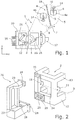
- eine perspektivische Ansicht der Werkzeugmaschine und der noch nicht angekoppelten Beladezelle;
- Fig. 3
- eine Detailansicht des in
Fig. 1 gezeigten Kopplungsbereichs der anein-ander gekoppelten Werkzeugmaschine und Beladezelle; - Fig. 4
- eine Kreisbogentür der Beladezelle in ihrer Geschlossenstellung; und
- Fig. 5
- eine Draufsicht von oben auf die Werkzeugmaschine von
Fig. 1 und einen zusätzlichen Werkstück-Palettenspeicher. - Bei der in
Fign. 1 und 2 insgesamt mit 1 bezeichneten Werkzeugmaschine zur spanenden Bearbeitung von Werkstücken ist im rahmenartigen Maschinengestell 2 um eine horizontale Achse 3 ein Werkstücktisch in Form eines Doppelschwenktischs (Doppelschwenkbalken) 4 schwenkbar gelagert, dessen einer Schwenktisch 4a (inFig. 1 der rechte) auf der Bearbeitungsseite 5 innerhalb eines Bearbeitungsraums und dessen anderer Schwenktisch 4b (inFig. 1 der linke) auf der Belade- oder Bestückungsseite 6 innerhalb eines Bestückungsraums vorgesehen sind. Durch Verschwenken (Doppelpfeil 7) des Doppelschwenktisches 4 um die horizontale Achse 3 um 180° lassen sich der bearbeitungsseitige Schwenktisch 4a und der bestückungsseitige Schwenktisch 4b vertauschen. Die beiden Schwenktische 4a, 4b sind zwischen und an zwei Schwenkscheiben 8, welche seitlich am Maschinengestell 2 um die horizontale Achse 3 gelagert sind, jeweils um eine horizontale Schwenkachse (A-Achse) 9 verschwenkbar (Doppelpfeil 10) gelagert. Die Bearbeitungs- und Bestückungsräume sind entweder jeweils in sich geschlossene Maschinenräume oder bilden gemeinsam einen in sich geschlossenen Maschinenraum. - Wie in
Fig. 2 gezeigt, ist der Doppelschwenktisch 4 an zwei einander gegenüberliegenden Seitenwänden 11 des Maschinengestells 2 drehbar gelagert, die unten durch einen Bodenträger 12 und oben durch einen Deckenträger 13 miteinander verbunden sind und beispielsweise zusammen mit den Boden- und dem Deckenträgern 12, 13 ein Monoblock-Rahmengestell ausbilden. - Der bestückungsseitige Schwenktisch 4b wird mit zu bearbeitenden Werkstücken 14 bestückt, die dann nach Vertauschen der Schwenktische 4a, 4b auf der Bearbeitungsseite 5 mittels eines in einer horizontalen Arbeitsspindel 15 aufgenommenen Werkzeuges 16 bearbeitet werden. Die horizontale Arbeitsspindel 15 ist mittels einer XYZ-Schlitteneinheit 17 an den einen, in
Fig. 1 rechten Stirnseiten der Seitenwände 11 befestigt. Zum Vertauschen der Schwenktische 4a, 4b wird der Doppelschwenktisch 4 in Schwenkrichtung 7 um 180° geschwenkt, wodurch sich mit vertauschten Schwenktischen 4a, 4b wieder die inFig. 1 gezeigte Anordnung ergibt. Zusätzlich können dabei auch einer oder beide Schwenktische 4a, 4b um ihre Schwenkachsen 9 in Schwenkrichtung 10 geschwenkt werden. - Zwischen und an den beiden Schwenkscheiben 8 ist eine feststehende Spritzschutzwand 18 befestigt, die in der in
Fig. 1 dargestellten Schwenkendposition des Doppelschwenktisches 4 die Bearbeitungs- und Bestückungsseiten 5, 6 voneinander trennt. Auf diese Weise kann während des Bearbeitens der Werkstücke 14 auf der Bearbeitungsseite 5 ein neues Werkstück 14 auf der Bestückungsseite aufgespannt werden, wobei das Bedienungspersonal vor spritzendem Bohrwasser oder herumfliegenden Bohrspänen etc. geschützt ist. - Wie in
Fig. 2 weiter gezeigt, ist an das Maschinengestell 2 seitlich eine Beladezelle 20 angekoppelt (angeflanscht), in deren Zelleninnenraum 21 ein (Greif)Roboter 22 zum automatischen Beladen des bestückungsseitigen Schwenktischs 4b mit zu bearbeitenden Werkstücken 14 und zum automatischen Entladen des bestückungsseitigen Schwenktischs 4b von bearbeiteten Werkstücken 14 hängend an einer Zellendecke 23 montiert ist. Vorzugsweise hat der Greifroboter 22 mindestens fünf Rotationsachsen und kann wie im gezeigten Ausführungsbeispiel mit zwei Gelenkarmen und einem Greifer ausgeführt sein. - Die Beladezelle 20 weist eine untere und eine obere, seitliche Befestigungsfläche (Flanschfläche) 24 auf, mit denen die Beladezelle 20 an entsprechenden, seitlichen Gegenbefestigungsflächen 25 des Boden- und des Deckenträgers 12, 13 befestigt ist. Wie in
Fig. 3 gezeigt, ist zwischen den zellenseitigen und den maschinengestellseitigen Befestigungsflächen 24, 25 jeweils eine Dämpfungsschicht 26 angeordnet, um das Maschinengestell 2 und die Beladezelle 20 voneinander bezüglich Vibrationen zu entkoppeln. - Die Beladezelle 20 weist ferner zur Bohrwasserableitung einen Zellenboden 27 mit einem Gefälle in Richtung einer Öffnung 28 auf, welche in der unteren Befestigungsfläche 24 vorhanden ist. Das Maschinengestell 2 wiederum hat innerhalb der unteren Gegenbefestigungsfläche 25 eine korrespondierende Öffnung 29, die zu einem nicht gezeigten (Wasser)Abfluss des Maschinengestells 2 führt. Bei angekoppelter Beladezelle 20 ist der Zellenboden 27 somit über die beiden Öffnungen 28, 29 an den Abfluss des Maschinengestells 2 angeschlossen. Bohrwasser, das von einem bearbeiteten Werkstück 14, welches gerade zurück auf die Bestückungsseite 6 verschwenkt worden ist, auf den Zellenboden 27 abtropft, wird dem Abfluss des Maschinengestells 2 zugeführt.
-
Fig. 4 zeigt eine um eine Vertikalachse zwischen einer Offen- und einer Geschlossenstellung verschwenkbar gelagerte Zellentür in Form einer Kreisbogentür 30, die den Zelleninnenraum 21 für einen außenstehenden Maschinenbediener in der Geschlossenstellung verschließt und in der Offenstellung freigibt. Die Kreisbogentür 30 hat ein Fenster 31, durch das hindurch der Greifroboter 22 in der inFig. 4 gezeigten Geschlossenstellung erkennbar ist. Die Kreisbogentür 30 weist einen kreissektorförmigen Türboden 32, der in der Geschlossenstellung unterhalb des Roboters 22 in den Zelleninnenraum 21 hineinragt, und einen kreissektorförmigen Türoberboden 33 auf, der in der Geschlossenstellung oberhalb der Zellendecke 23 angeordnet ist und somit das Zellendach der Beladezelle 20 ausbildet. Der Türboden 32 hat ein in Richtung Vertikalachse verlaufendes Gefälle und befindet sich etwa auf halber Höhe eines vor der Beladezelle 20 stehenden Maschinenbedieners. - Der vollautomatische Be- und Entladevorgang von Werkstücken 14 mittels des Roboters 22 findet bei geschlossener Kreisbogentür 30 durch eine in
Fig. 2 gezeigte Beladeöffnung 34 des Maschinengestells 2 statt, während das Robotereinrichten, das manuelle Be- und Entladen von Werkstücken 14 sowie das Werkstückumrüsten vom Maschinenbediener bei geöffneter Kreisbogentür 30 vorgenommen werden. - Wie in
Fig. 5 gezeigt, ist die Beladezelle 20 zwischen dem Maschinengestell 2 einerseits und einem vertikalen Werkstück-Palettenspeicher 35 andererseits angeordnet. Der Palettenspeicher 35 kann beispielsweise an der Beladezelle 20 höhenverfahrbar geführt sein, wie inFig. 1 gezeigt ist, oder am Maschinengestell 2 angekoppelt sein. Üblicherweise beinhaltet der Palettenspeicher 35 mehrere in den Zelleninnenraum 21 ausziehbare Schubladen, auf denen die zu bearbeitenden und die bearbeiteten Werkstücke 14 abgelegt sind. Für den an der Zellendecke 23 herunter hängenden Greifroboter 22 stellen ausgezogene Schubladen kein Hindernis dar, was einfache und schnelle Roboterbewegungen ermöglicht. Statt eines Palettenspeichers 35 kann auch ein Transportbandes oder auch eine Stapelzelle für die Werkstückzu- und -abfuhr vorgesehen sein.
Claims (13)
- Werkzeugmaschine (1) zur insbesondere spanenden Bearbeitung von Werkstücken (14), aufweisend einen an einem Maschinengestell (2) drehbar gelagerten Werkstücktisch (4), insbesondere Doppelschwenkträger, für zu bearbeitende Werkstücke (14), und eine am Maschinengestell (2) gehaltene, insbesondere horizontale Werkzeugspindel (15) mit einem Werkzeug (16) zum Bearbeiten von Werkstücken (14),
dadurch gekennzeichnet,
dass ein Roboter (22) zum Beladen des Werkstücktischs (4) mit zu bearbeitenden Werkstücken (14) und zum Entladen des Werkstücktischs (4) von bearbeiteten Werkstücken (14) in einer Beladezelle (20), welche an das Maschinengestell (2) seitlich angekoppelt ist, hängend gehalten ist,
dass die Beladezelle (20) eine um eine Vertikalachse zwischen einer Offen- und einer Geschlossenstellung verschwenkbare Zellentür (30), insbesondere Kreisbogentür, aufweist, die den Zelleninnenraum (21) in der Geschlossenstellung verschließt und in der Offenstellung freigibt, und
dass die Zellentür (30) einen insbesondere kreissektorförmigen Türboden (32) aufweist, der zumindest in der Geschlossenstellung unterhalb des Roboters (22) in den Zelleninnenraum (21) hineinragt. - Werkzeugmaschine nach Anspruch 1, dadurch gekennzeichnet, dass der Roboter (22) an der Zellendecke (23) der Beladezelle (20) hängend gehalten ist.
- Werkzeugmaschine nach Anspruch 1 oder 2, dadurch gekennzeichnet, dass die Zellentür (30) einen insbesondere kreissektorförmigen Türoberboden (33) aufweist, der zumindest in der Geschlossenstellung oberhalb des Roboters (22) angeordnet ist.
- Werkzeugmaschine nach einem der vorhergehenden Ansprüche, dadurch gekennzeichnet, dass der Türboden (32) ein Gefälle aufweist.
- Werkzeugmaschine nach einem der vorhergehenden Ansprüche, dadurch gekennzeichnet, dass der Türboden (32) mindestens auf halber Höhe eines vor der Beladezelle (20) stehenden Maschinenbedieners angeordnet ist.
- Werkzeugmaschine nach einem der vorhergehenden Ansprüche, dadurch gekennzeichnet, dass die Beladezelle (20) mit mindestens einer Befestigungsfläche (24), insbesondere mit einer unteren und einer oberen Befestigungsfläche (24), an mindestens einer Gegenbefestigungsfläche (25) des Maschinengestells (2) befestigt ist.
- Werkzeugmaschine nach Anspruch 6, dadurch gekennzeichnet, dass zwischen einer Befestigungsfläche (24) der Beladezelle (20) und der Gegenbefestigungsfläche (25) des Maschinengestells (2) eine Dämpfungsschicht (26) angeordnet ist.
- Werkzeugmaschine nach einem der vorhergehenden Ansprüche, dadurch gekennzeichnet, dass die Beladezelle (20) einen mit Gefälle versehenen Zellenboden (27) aufweist, der an einen Abfluss des Maschinengestells (2) angebunden ist.
- Werkzeugmaschine nach Anspruch 8, dadurch gekennzeichnet, dass die Abflussanbindung durch Öffnungen (28, 29) gebildet ist, die jeweils in aneinander anliegende Schnittstellflächen der Beladezelle (20) und des Maschinengestells (2) münden.
- Werkzeugmaschine nach einem der vorhergehenden Ansprüche, dadurch gekennzeichnet, dass die Beladezelle (20) zwischen dem Maschinengestell (2) einerseits und einem Werkstückspeicher oder -förderer (35) andererseits angeordnet ist.
- Werkzeugmaschine nach Anspruch 10, dadurch gekennzeichnet, dass der Werkstückspeicher oder -förderer (35) an dem Maschinengestell (2) oder an der Beladezelle (20) angekoppelt ist.
- Werkzeugmaschine nach einem der vorhergehenden Ansprüche, dadurch gekennzeichnet, dass der Werkstücktisch (4) an zwei einander gegenüberliegenden Seitenwänden (11) des Maschinengestells (2) um eine horizontale Achse (3) drehbar gelagert ist und dass die zwei Seitenwände (11) unten durch einen Bodenträger (12) und oben durch einen Deckenträger (13) miteinander verbunden sind.
- Werkzeugmaschine nach Anspruch 12, dadurch gekennzeichnet, dass die zwei einander gegenüberliegenden Seitenwände (11) zusammen mit dem Bodenträger (12) und dem Deckenträger (13) ein Monoblock-Rahmengestell bilden.
Priority Applications (3)
| Application Number | Priority Date | Filing Date | Title |
|---|---|---|---|
| ES17169245T ES2727783T3 (es) | 2017-05-03 | 2017-05-03 | Máquina-herramienta con celda de carga por robot modular |
| EP17169245.2A EP3398711B1 (de) | 2017-05-03 | 2017-05-03 | Werkzeugmaschine mit modularer roboter-beladezelle |
| CN201810351919.3A CN108788883B (zh) | 2017-05-03 | 2018-04-19 | 具有模块化的机器人装载单元的工具机 |
Applications Claiming Priority (1)
| Application Number | Priority Date | Filing Date | Title |
|---|---|---|---|
| EP17169245.2A EP3398711B1 (de) | 2017-05-03 | 2017-05-03 | Werkzeugmaschine mit modularer roboter-beladezelle |
Publications (2)
| Publication Number | Publication Date |
|---|---|
| EP3398711A1 EP3398711A1 (de) | 2018-11-07 |
| EP3398711B1 true EP3398711B1 (de) | 2019-04-10 |
Family
ID=58668795
Family Applications (1)
| Application Number | Title | Priority Date | Filing Date |
|---|---|---|---|
| EP17169245.2A Active EP3398711B1 (de) | 2017-05-03 | 2017-05-03 | Werkzeugmaschine mit modularer roboter-beladezelle |
Country Status (3)
| Country | Link |
|---|---|
| EP (1) | EP3398711B1 (de) |
| CN (1) | CN108788883B (de) |
| ES (1) | ES2727783T3 (de) |
Families Citing this family (6)
| Publication number | Priority date | Publication date | Assignee | Title |
|---|---|---|---|---|
| EP3107685A1 (de) * | 2014-02-21 | 2016-12-28 | SK-Technologies UG | Roboterzelle zum hauptzeitparallelen be- und entladen von einzelplatz-zerspanungsmaschinen |
| JP7288367B2 (ja) * | 2019-08-14 | 2023-06-07 | オークマ株式会社 | 工作機械システム |
| JP7371774B2 (ja) * | 2020-05-18 | 2023-10-31 | 村田機械株式会社 | 工作機械システム |
| DE102021113890A1 (de) * | 2021-05-28 | 2022-12-01 | Chiron Group Se | Fertigungssystem und Anlage zur spanenden Fertigung |
| DE102022122977A1 (de) * | 2022-09-09 | 2024-03-14 | Chiron Group Se | Handhabungszelle für eine Werkzeugmaschine und Fertigungssystem |
| CN117985479B (zh) * | 2024-04-03 | 2024-06-11 | 常州宝捷冲片有限公司 | 自动码垛设备及其工作方法 |
Family Cites Families (9)
| Publication number | Priority date | Publication date | Assignee | Title |
|---|---|---|---|---|
| DE19857012C3 (de) | 1998-12-09 | 2002-10-24 | Schwaebische Werkzeugmaschinen | Werkzeugmaschine mit horizontal angeordneter Arbeitsspindel |
| DE10334677B3 (de) * | 2003-07-30 | 2004-11-25 | Schwäbische Werkzeugmaschinen GmbH | Werkzeugmaschine mit hauptzeitparalleler Spänesiebreinigung |
| DE102006052933B3 (de) * | 2006-11-08 | 2007-10-31 | Schwäbische Werkzeugmaschinen GmbH | Werkzeugmaschine für manuelle Beladung |
| AT505728B1 (de) * | 2007-09-13 | 2011-04-15 | Promot Automation Gmbh | Bearbeitungsanlage für werkstücke |
| JP4603604B2 (ja) * | 2008-08-01 | 2010-12-22 | ファナック株式会社 | ロボットにより工作機械へワークの着脱を行うロボットシステム |
| CN203993345U (zh) * | 2014-05-30 | 2014-12-10 | 广州数控设备有限公司 | 一种龙门侧挂式移动机器人自动上下料装置 |
| DE102014007832B4 (de) * | 2014-06-02 | 2019-03-14 | Hermann Müller | Maschinenrahmen für ein hängendes Robotersystem |
| DE102015118031B4 (de) * | 2015-10-22 | 2017-07-13 | Gebr. Heller Maschinenfabrik Gmbh | Einhausung für eine Werkzeugmaschine |
| CN205237157U (zh) * | 2015-11-20 | 2016-05-18 | 埃马克(中国)机械有限公司 | 用于并行加工的机床 |
-
2017
- 2017-05-03 ES ES17169245T patent/ES2727783T3/es active Active
- 2017-05-03 EP EP17169245.2A patent/EP3398711B1/de active Active
-
2018
- 2018-04-19 CN CN201810351919.3A patent/CN108788883B/zh active Active
Non-Patent Citations (1)
| Title |
|---|
| None * |
Also Published As
| Publication number | Publication date |
|---|---|
| CN108788883B (zh) | 2022-03-29 |
| CN108788883A (zh) | 2018-11-13 |
| EP3398711A1 (de) | 2018-11-07 |
| ES2727783T3 (es) | 2019-10-18 |
Similar Documents
| Publication | Publication Date | Title |
|---|---|---|
| EP3398711A1 (de) | Werkzeugmaschine mit modularer roboter-beladezelle | |
| DE102006024407B4 (de) | Werkzeugmaschine | |
| DE3139962C2 (de) | Werkzeugmaschine mit Spanfördereinrichtung | |
| DE102009035637B4 (de) | Robotersystem, das einen Roboter verwendet, um ein Werkstück in und aus einer Werkzeugmaschine ein- und auszuladen | |
| DE102004046996B4 (de) | Werkzeugmaschine | |
| EP1754568A1 (de) | Werkzeugmaschine mit automatischer Abdeckung im Dachbereich | |
| DE10252824A1 (de) | Werkzeugmaschine | |
| EP0721819A1 (de) | Werkzeugmaschine | |
| CH709579B1 (de) | Werkzeugmaschine. | |
| DE102006025143A1 (de) | Werkzeugmaschine | |
| EP2945776B1 (de) | Werkzeug-maschine mit palettenwechsler | |
| DE102010064271A1 (de) | Programmgesteuerte Werkzeugmaschine | |
| DE102010005630B4 (de) | Komplettbearbeitung von Werkzeugen | |
| EP1522391B1 (de) | Werkzeugmaschine sowie Verfahren zur Bearbeitung von Werkstücken mittels Wasserstrahl | |
| EP2370230B1 (de) | Bearbeitungszentrum | |
| DE10258734A1 (de) | Werkzeugmaschine | |
| DE19913715C1 (de) | Reinigungsverfahren für die Bestückungsseite einer Werkzeugmaschine und zugehörige Werkzeugmaschine | |
| EP3299119B1 (de) | Nachbearbeitungsverfahren für die bestückungsseite einer werkzeugmaschine und zugehörige werkzeugmaschine | |
| EP1321224B1 (de) | Werkstückträger-Wechseleinrichtung für Werkzeugmaschinen | |
| EP4277767B1 (de) | Handhabungsanordnung einer werkzeugmaschine | |
| DE60000747T2 (de) | Ladestation mit Schleuse | |
| DE19861132B4 (de) | Werkzeugmaschine mit Abdeckung | |
| DE202004020485U1 (de) | Palettenwechsler | |
| DE102007044288B4 (de) | Werkzeugmaschine mit einem ersten und einem zweiten Werkstückträger und Werkstückbearbeitungsverfahren | |
| DE102004006757B4 (de) | Werkzeugmaschine |
Legal Events
| Date | Code | Title | Description |
|---|---|---|---|
| PUAI | Public reference made under article 153(3) epc to a published international application that has entered the european phase |
Free format text: ORIGINAL CODE: 0009012 |
|
| STAA | Information on the status of an ep patent application or granted ep patent |
Free format text: STATUS: REQUEST FOR EXAMINATION WAS MADE |
|
| 17P | Request for examination filed |
Effective date: 20171124 |
|
| AK | Designated contracting states |
Kind code of ref document: A1 Designated state(s): AL AT BE BG CH CY CZ DE DK EE ES FI FR GB GR HR HU IE IS IT LI LT LU LV MC MK MT NL NO PL PT RO RS SE SI SK SM TR |
|
| AX | Request for extension of the european patent |
Extension state: BA ME |
|
| GRAP | Despatch of communication of intention to grant a patent |
Free format text: ORIGINAL CODE: EPIDOSNIGR1 |
|
| STAA | Information on the status of an ep patent application or granted ep patent |
Free format text: STATUS: GRANT OF PATENT IS INTENDED |
|
| INTG | Intention to grant announced |
Effective date: 20181214 |
|
| GRAS | Grant fee paid |
Free format text: ORIGINAL CODE: EPIDOSNIGR3 |
|
| GRAA | (expected) grant |
Free format text: ORIGINAL CODE: 0009210 |
|
| STAA | Information on the status of an ep patent application or granted ep patent |
Free format text: STATUS: THE PATENT HAS BEEN GRANTED |
|
| AK | Designated contracting states |
Kind code of ref document: B1 Designated state(s): AL AT BE BG CH CY CZ DE DK EE ES FI FR GB GR HR HU IE IS IT LI LT LU LV MC MK MT NL NO PL PT RO RS SE SI SK SM TR |
|
| REG | Reference to a national code |
Ref country code: GB Ref legal event code: FG4D Free format text: NOT ENGLISH |
|
| REG | Reference to a national code |
Ref country code: CH Ref legal event code: EP Ref country code: AT Ref legal event code: REF Ref document number: 1118030 Country of ref document: AT Kind code of ref document: T Effective date: 20190415 |
|
| REG | Reference to a national code |
Ref country code: IE Ref legal event code: FG4D Free format text: LANGUAGE OF EP DOCUMENT: GERMAN |
|
| REG | Reference to a national code |
Ref country code: DE Ref legal event code: R096 Ref document number: 502017001070 Country of ref document: DE |
|
| REG | Reference to a national code |
Ref country code: NL Ref legal event code: MP Effective date: 20190410 |
|
| REG | Reference to a national code |
Ref country code: LT Ref legal event code: MG4D |
|
| PG25 | Lapsed in a contracting state [announced via postgrant information from national office to epo] |
Ref country code: NL Free format text: LAPSE BECAUSE OF FAILURE TO SUBMIT A TRANSLATION OF THE DESCRIPTION OR TO PAY THE FEE WITHIN THE PRESCRIBED TIME-LIMIT Effective date: 20190410 |
|
| REG | Reference to a national code |
Ref country code: ES Ref legal event code: FG2A Ref document number: 2727783 Country of ref document: ES Kind code of ref document: T3 Effective date: 20191018 |
|
| PG25 | Lapsed in a contracting state [announced via postgrant information from national office to epo] |
Ref country code: NO Free format text: LAPSE BECAUSE OF FAILURE TO SUBMIT A TRANSLATION OF THE DESCRIPTION OR TO PAY THE FEE WITHIN THE PRESCRIBED TIME-LIMIT Effective date: 20190710 Ref country code: FI Free format text: LAPSE BECAUSE OF FAILURE TO SUBMIT A TRANSLATION OF THE DESCRIPTION OR TO PAY THE FEE WITHIN THE PRESCRIBED TIME-LIMIT Effective date: 20190410 Ref country code: LT Free format text: LAPSE BECAUSE OF FAILURE TO SUBMIT A TRANSLATION OF THE DESCRIPTION OR TO PAY THE FEE WITHIN THE PRESCRIBED TIME-LIMIT Effective date: 20190410 Ref country code: HR Free format text: LAPSE BECAUSE OF FAILURE TO SUBMIT A TRANSLATION OF THE DESCRIPTION OR TO PAY THE FEE WITHIN THE PRESCRIBED TIME-LIMIT Effective date: 20190410 Ref country code: PT Free format text: LAPSE BECAUSE OF FAILURE TO SUBMIT A TRANSLATION OF THE DESCRIPTION OR TO PAY THE FEE WITHIN THE PRESCRIBED TIME-LIMIT Effective date: 20190910 Ref country code: AL Free format text: LAPSE BECAUSE OF FAILURE TO SUBMIT A TRANSLATION OF THE DESCRIPTION OR TO PAY THE FEE WITHIN THE PRESCRIBED TIME-LIMIT Effective date: 20190410 Ref country code: SE Free format text: LAPSE BECAUSE OF FAILURE TO SUBMIT A TRANSLATION OF THE DESCRIPTION OR TO PAY THE FEE WITHIN THE PRESCRIBED TIME-LIMIT Effective date: 20190410 |
|
| PG25 | Lapsed in a contracting state [announced via postgrant information from national office to epo] |
Ref country code: GR Free format text: LAPSE BECAUSE OF FAILURE TO SUBMIT A TRANSLATION OF THE DESCRIPTION OR TO PAY THE FEE WITHIN THE PRESCRIBED TIME-LIMIT Effective date: 20190711 Ref country code: PL Free format text: LAPSE BECAUSE OF FAILURE TO SUBMIT A TRANSLATION OF THE DESCRIPTION OR TO PAY THE FEE WITHIN THE PRESCRIBED TIME-LIMIT Effective date: 20190410 Ref country code: RS Free format text: LAPSE BECAUSE OF FAILURE TO SUBMIT A TRANSLATION OF THE DESCRIPTION OR TO PAY THE FEE WITHIN THE PRESCRIBED TIME-LIMIT Effective date: 20190410 Ref country code: LV Free format text: LAPSE BECAUSE OF FAILURE TO SUBMIT A TRANSLATION OF THE DESCRIPTION OR TO PAY THE FEE WITHIN THE PRESCRIBED TIME-LIMIT Effective date: 20190410 Ref country code: BG Free format text: LAPSE BECAUSE OF FAILURE TO SUBMIT A TRANSLATION OF THE DESCRIPTION OR TO PAY THE FEE WITHIN THE PRESCRIBED TIME-LIMIT Effective date: 20190710 |
|
| PG25 | Lapsed in a contracting state [announced via postgrant information from national office to epo] |
Ref country code: IS Free format text: LAPSE BECAUSE OF FAILURE TO SUBMIT A TRANSLATION OF THE DESCRIPTION OR TO PAY THE FEE WITHIN THE PRESCRIBED TIME-LIMIT Effective date: 20190810 |
|
| REG | Reference to a national code |
Ref country code: DE Ref legal event code: R097 Ref document number: 502017001070 Country of ref document: DE |
|
| PG25 | Lapsed in a contracting state [announced via postgrant information from national office to epo] |
Ref country code: SK Free format text: LAPSE BECAUSE OF FAILURE TO SUBMIT A TRANSLATION OF THE DESCRIPTION OR TO PAY THE FEE WITHIN THE PRESCRIBED TIME-LIMIT Effective date: 20190410 Ref country code: RO Free format text: LAPSE BECAUSE OF FAILURE TO SUBMIT A TRANSLATION OF THE DESCRIPTION OR TO PAY THE FEE WITHIN THE PRESCRIBED TIME-LIMIT Effective date: 20190410 Ref country code: CZ Free format text: LAPSE BECAUSE OF FAILURE TO SUBMIT A TRANSLATION OF THE DESCRIPTION OR TO PAY THE FEE WITHIN THE PRESCRIBED TIME-LIMIT Effective date: 20190410 Ref country code: MC Free format text: LAPSE BECAUSE OF FAILURE TO SUBMIT A TRANSLATION OF THE DESCRIPTION OR TO PAY THE FEE WITHIN THE PRESCRIBED TIME-LIMIT Effective date: 20190410 Ref country code: EE Free format text: LAPSE BECAUSE OF FAILURE TO SUBMIT A TRANSLATION OF THE DESCRIPTION OR TO PAY THE FEE WITHIN THE PRESCRIBED TIME-LIMIT Effective date: 20190410 Ref country code: DK Free format text: LAPSE BECAUSE OF FAILURE TO SUBMIT A TRANSLATION OF THE DESCRIPTION OR TO PAY THE FEE WITHIN THE PRESCRIBED TIME-LIMIT Effective date: 20190410 |
|
| REG | Reference to a national code |
Ref country code: BE Ref legal event code: MM Effective date: 20190531 |
|
| PLBE | No opposition filed within time limit |
Free format text: ORIGINAL CODE: 0009261 |
|
| STAA | Information on the status of an ep patent application or granted ep patent |
Free format text: STATUS: NO OPPOSITION FILED WITHIN TIME LIMIT |
|
| PG25 | Lapsed in a contracting state [announced via postgrant information from national office to epo] |
Ref country code: SM Free format text: LAPSE BECAUSE OF FAILURE TO SUBMIT A TRANSLATION OF THE DESCRIPTION OR TO PAY THE FEE WITHIN THE PRESCRIBED TIME-LIMIT Effective date: 20190410 Ref country code: LU Free format text: LAPSE BECAUSE OF NON-PAYMENT OF DUE FEES Effective date: 20190503 |
|
| 26N | No opposition filed |
Effective date: 20200113 |
|
| PG25 | Lapsed in a contracting state [announced via postgrant information from national office to epo] |
Ref country code: TR Free format text: LAPSE BECAUSE OF FAILURE TO SUBMIT A TRANSLATION OF THE DESCRIPTION OR TO PAY THE FEE WITHIN THE PRESCRIBED TIME-LIMIT Effective date: 20190410 |
|
| PG25 | Lapsed in a contracting state [announced via postgrant information from national office to epo] |
Ref country code: IE Free format text: LAPSE BECAUSE OF NON-PAYMENT OF DUE FEES Effective date: 20190503 |
|
| PG25 | Lapsed in a contracting state [announced via postgrant information from national office to epo] |
Ref country code: BE Free format text: LAPSE BECAUSE OF NON-PAYMENT OF DUE FEES Effective date: 20190531 |
|
| PG25 | Lapsed in a contracting state [announced via postgrant information from national office to epo] |
Ref country code: LI Free format text: LAPSE BECAUSE OF NON-PAYMENT OF DUE FEES Effective date: 20200531 Ref country code: CH Free format text: LAPSE BECAUSE OF NON-PAYMENT OF DUE FEES Effective date: 20200531 |
|
| PG25 | Lapsed in a contracting state [announced via postgrant information from national office to epo] |
Ref country code: CY Free format text: LAPSE BECAUSE OF FAILURE TO SUBMIT A TRANSLATION OF THE DESCRIPTION OR TO PAY THE FEE WITHIN THE PRESCRIBED TIME-LIMIT Effective date: 20190410 |
|
| PG25 | Lapsed in a contracting state [announced via postgrant information from national office to epo] |
Ref country code: HU Free format text: LAPSE BECAUSE OF FAILURE TO SUBMIT A TRANSLATION OF THE DESCRIPTION OR TO PAY THE FEE WITHIN THE PRESCRIBED TIME-LIMIT; INVALID AB INITIO Effective date: 20170503 Ref country code: MT Free format text: LAPSE BECAUSE OF FAILURE TO SUBMIT A TRANSLATION OF THE DESCRIPTION OR TO PAY THE FEE WITHIN THE PRESCRIBED TIME-LIMIT Effective date: 20190410 |
|
| PG25 | Lapsed in a contracting state [announced via postgrant information from national office to epo] |
Ref country code: SI Free format text: LAPSE BECAUSE OF FAILURE TO SUBMIT A TRANSLATION OF THE DESCRIPTION OR TO PAY THE FEE WITHIN THE PRESCRIBED TIME-LIMIT Effective date: 20190410 |
|
| GBPC | Gb: european patent ceased through non-payment of renewal fee |
Effective date: 20210503 |
|
| PG25 | Lapsed in a contracting state [announced via postgrant information from national office to epo] |
Ref country code: GB Free format text: LAPSE BECAUSE OF NON-PAYMENT OF DUE FEES Effective date: 20210503 |
|
| PG25 | Lapsed in a contracting state [announced via postgrant information from national office to epo] |
Ref country code: MK Free format text: LAPSE BECAUSE OF FAILURE TO SUBMIT A TRANSLATION OF THE DESCRIPTION OR TO PAY THE FEE WITHIN THE PRESCRIBED TIME-LIMIT Effective date: 20190410 |
|
| PGFP | Annual fee paid to national office [announced via postgrant information from national office to epo] |
Ref country code: DE Payment date: 20250527 Year of fee payment: 9 |
|
| PGFP | Annual fee paid to national office [announced via postgrant information from national office to epo] |
Ref country code: ES Payment date: 20250616 Year of fee payment: 9 |
|
| PGFP | Annual fee paid to national office [announced via postgrant information from national office to epo] |
Ref country code: IT Payment date: 20250530 Year of fee payment: 9 |
|
| PGFP | Annual fee paid to national office [announced via postgrant information from national office to epo] |
Ref country code: FR Payment date: 20250523 Year of fee payment: 9 |
|
| PGFP | Annual fee paid to national office [announced via postgrant information from national office to epo] |
Ref country code: AT Payment date: 20250519 Year of fee payment: 9 |