EP3398704A1 - Wire supplying and receiving device for a wire saw, ingot slicing wire saw including the same, and method of slicing ingot - Google Patents
Wire supplying and receiving device for a wire saw, ingot slicing wire saw including the same, and method of slicing ingot Download PDFInfo
- Publication number
- EP3398704A1 EP3398704A1 EP18169295.5A EP18169295A EP3398704A1 EP 3398704 A1 EP3398704 A1 EP 3398704A1 EP 18169295 A EP18169295 A EP 18169295A EP 3398704 A1 EP3398704 A1 EP 3398704A1
- Authority
- EP
- European Patent Office
- Prior art keywords
- wire
- supplying
- receiving device
- winding unit
- rotating member
- Prior art date
- Legal status (The legal status is an assumption and is not a legal conclusion. Google has not performed a legal analysis and makes no representation as to the accuracy of the status listed.)
- Withdrawn
Links
Images


Classifications
-
- B—PERFORMING OPERATIONS; TRANSPORTING
- B23—MACHINE TOOLS; METAL-WORKING NOT OTHERWISE PROVIDED FOR
- B23D—PLANING; SLOTTING; SHEARING; BROACHING; SAWING; FILING; SCRAPING; LIKE OPERATIONS FOR WORKING METAL BY REMOVING MATERIAL, NOT OTHERWISE PROVIDED FOR
- B23D57/00—Sawing machines or sawing devices not covered by one of the preceding groups B23D45/00 - B23D55/00
- B23D57/003—Sawing machines or sawing devices working with saw wires, characterised only by constructional features of particular parts
- B23D57/0053—Sawing machines or sawing devices working with saw wires, characterised only by constructional features of particular parts of drives for saw wires; of wheel mountings; of wheels
-
- B—PERFORMING OPERATIONS; TRANSPORTING
- B28—WORKING CEMENT, CLAY, OR STONE
- B28D—WORKING STONE OR STONE-LIKE MATERIALS
- B28D5/00—Fine working of gems, jewels, crystals, e.g. of semiconductor material; apparatus or devices therefor
- B28D5/04—Fine working of gems, jewels, crystals, e.g. of semiconductor material; apparatus or devices therefor by tools other than rotary type, e.g. reciprocating tools
- B28D5/042—Fine working of gems, jewels, crystals, e.g. of semiconductor material; apparatus or devices therefor by tools other than rotary type, e.g. reciprocating tools by cutting with blades or wires mounted in a reciprocating frame
-
- B—PERFORMING OPERATIONS; TRANSPORTING
- B28—WORKING CEMENT, CLAY, OR STONE
- B28D—WORKING STONE OR STONE-LIKE MATERIALS
- B28D5/00—Fine working of gems, jewels, crystals, e.g. of semiconductor material; apparatus or devices therefor
- B28D5/0058—Accessories specially adapted for use with machines for fine working of gems, jewels, crystals, e.g. of semiconductor material
-
- B—PERFORMING OPERATIONS; TRANSPORTING
- B28—WORKING CEMENT, CLAY, OR STONE
- B28D—WORKING STONE OR STONE-LIKE MATERIALS
- B28D5/00—Fine working of gems, jewels, crystals, e.g. of semiconductor material; apparatus or devices therefor
- B28D5/04—Fine working of gems, jewels, crystals, e.g. of semiconductor material; apparatus or devices therefor by tools other than rotary type, e.g. reciprocating tools
- B28D5/045—Fine working of gems, jewels, crystals, e.g. of semiconductor material; apparatus or devices therefor by tools other than rotary type, e.g. reciprocating tools by cutting with wires or closed-loop blades
Definitions
- the disclosure relates to a wire supplying and receiving device, an ingot slicing wire saw including the same, and a method of slicing ingot.
- ingots are sliced by metal wires carrying cutting slurry to form a plurality of wafers.
- the cutting slurry is made by mixing particles and liquid or oil.
- wire saws mounted with abrasive particles e.g., diamond particles
- abrasive particles e.g., diamond particles
- the wire saws are wound around two main rollers of an ingot slicing apparatus, and around a first wire winding roller and a second wire winding roller that are located opposite to each other with respect to the main rollers to form a wire net between the main rollers.
- the wire net slices the ingot.
- the sawing wires are either moved unidirectionally from the first wire winding roller onto the second wire winding roller or moved reciprocally between the main rollers. The latter is more economic in terms of sawing wire usage, and is widely used.
- the sawing wires are coiled around the first and second wire winding rollers, when portions of the sawing wires are being wound on or leaving the rollers, they move relative to the remaining portions of the sawing wires coiled thereunder, resulting in undesirable wear.
- the degree of wear of the abrasive particles should be taken into account when performing slicing action.
- Taiwanese Invention Patent Application No. 201501844 A teaches a method of managing sawing wires.
- TW 201501844 A discloses a first wire winding roller and a second wire roller, each of which has a main wire winding region and an auxiliary wire winding region adjacent to the main wire winding region.
- Unused sections (i.e., that have been not yet used to cut) of the sawing wires and used sections (i.e., that have been used to cut) of the sawing wires are wound on different wire winding regions to avoid wear occurring between unused and used sections of the sawing wires sawing wires.
- the quality of sliced wafers is not good enough.
- an object of the disclosure is to provide a wire supplying and receiving device for a wire saw, an ingot slicing wire saw including the same, and a method of slicing ingot that can alleviate at least one of the drawbacks of the prior art.
- the wire supplying and receiving device for a wire saw includes a moving unit, a first wire winding unit and a second wire winding unit.
- the moving unit includes a rail that extends along a first horizontal direction.
- the first wire winding unit is disposed on the rail and is rotatable about an axis parallel to the first horizontal direction.
- the second wire winding unit is disposed on the rail and is rotatable about the axis. At least one of the first wire winding unit and the second wire winding unit is movable on the rail along the first horizontal direction.
- the wire supplying and receiving device is convertible between a connected state, where the first and second wire winding units are adjacent to each other, and a disconnected state, where the first wire winding unit and the second wire winding unit are spaced apart from each other in the first horizontal direction.
- the ingot slicing wire saw is adapted to be mounted with a sawing wire for slicing an ingot.
- the ingot slicing wire saw includes a machine bed, a roller device, a feeding device and two of the aforementioned wire supplying and receiving devices.
- the roller device includes two main rollers rotatably connected to the machine bed and horizontally spaced apart from each other.
- the feeding device is disposed on the machine bed and above the roller device, and includes a feeding seat adapted for the ingot to be mounted thereon and operable to carry the ingot to move between the main rollers.
- the wire supplying and receiving devices are respectively disposed at opposite sides of the machine bed.
- the sawing wire is wound on the wire supplying and receiving devices and the main rollers of the roller device to form a wire net having a plurality of sawing sections spanning a space between the main rollers and adapted for slicing the ingot.
- the method for slicing an ingot includes:
- an embodiment of an ingot slicing wire saw 100 is adapted to be mounted with a sawing wire 91 for slicing an ingot 92.
- the ingot slicing wire saw 100 includes a machine bed 1, a roller device 2, a feeding device 3, two wire supplying and receiving devices 4, and two tension adjusting devices 5.
- a three-dimensional coordinate system having a first horizontal direction (X), a second horizontal direction (Y) and a height direction (Z) that are perpendicular to each other is defined for illustration purpose.
- the machine bed 1 includes a base section 11, a slicing seat section 12 and two roller installation sections 13.
- the slicing seat section 12 is disposed on the base section 11, extends upwardly along the height direction (Z), and is mounted with the roller device 2.
- the roller installation sections 13 are respectively disposed at opposite sides of the slicing seat section 12 along the second horizontal direction (Y).
- the roller device 2 includes two main rollers 21 rotatably connected to the machine bed 1 and horizontally spaced apart from each other.
- the sawing wire 91 is wound on the wire supplying and receiving devices 4 and the main rollers 21 of the roller device 2 to form a wire net 911 (see FIG. 3 ) having a plurality of sawing sections spanning a space between the main rollers 21 and adapted for slicing the ingot 92.
- the sawing sections of the wire net 911 are moved reciprocally in the second horizontal direction (Y) by the main rollers 21 to slice the ingot 92.
- the feeding device 3 is disposed on the machine bed 1 and above the roller device 2, and includes a feeding seat 31 and a broken wafer receiving box 32.
- the feeding seat 31 is adapted for the ingot 92 to be mounted thereon and is operable to carry the ingot 92 to move between the main rollers 21.
- the broken wafer receiving box 32 is located under the feeding seat 31, and is used for receiving broken pieces of the ingot 92.
- the wire supplying and receiving devices 4 are respectively located at opposite sides of the machine bed 1. As shown in FIG. 4 , the sawing wire 91 sequentially extends on one of the wire supplying and receiving devices 4, the roller device 2 and the other one of the wire supplying and receiving devices 4.
- the roller device 2 further includes two auxiliary rollers 22 that are disposed below the feeding device 3 and that are disposed between the main rollers 21.
- Lowermost side of each of the auxiliary rollers 22 is not higher than uppermost side of each of the main rollers 21.
- Diameter of each of the auxiliary rollers 22 is smaller than one-half of diameter of each of the main rollers 21.
- the sawing wire 91 is wound on the wire supplying and receiving devices 4, the main rollers 21 and the auxiliary rollers 22 to form the wire net 911 having the sawing sections spanning a space between the auxiliary rollers 22 and adapted for slicing the ingot 92.
- the synergy between the wire supplying and receiving devices 4 and the auxiliary rollers 22 contributes to the quality and stability of the sawing wire 91 during slicing.
- the relative position and size between the main rollers 21 and the auxiliary rollers 22 also contributes to the quality and stability of the sawing wire 91 during slicing.
- Such configuration allows the use of sawing wire 91 with smaller diameter (such as 40 ⁇ 60 micrometer), and reduces the possibility of wire breakage, especially in the case of using the hollow auxiliary rollers 22.
- each of the wire supplying and receiving devices 4 includes a moving unit 41, a first wire winding unit 42, a second wire winding unit 43 and a driving unit 44.
- the wire supplying and receiving device 4 includes two rails 411, a first moving seat 412 and a second moving seat 413. Each of the rails 411 extends along the first horizontal direction (X). The first and second moving seats 412, 413 are movably disposed on the rails 411. In certain embodiments, the wire supplying and receiving device 4 may include only one rail 411, as long as the first and second moving seats 412, 413 mounted on the rail 411 can move along the first horizontal direction (X). In certain embodiments, the rails 411 may be non-continuous, as long as there are rails provided in the movement range of the first and second moving seats 412, 413.
- the first wire winding unit 42 and the second wire winding unit 43 are rotatably and respectively mounted to the first moving seat 412 and the second moving seat 413. Specifically, each of the first wire winding unit 42 and the second wire winding unit 43 extends along the first horizontal direction (X), and is rotatable about an axis (L1) parallel to the first horizontal direction (X).
- the first wire winding unit 42 of the wire supplying and receiving device 4 includes a first rotating member 421 and a wire guiding seat. 6.
- the first rotating member 421 is rotatably mounted to the first moving seat 412.
- the wire guiding seat 6 is detachably mounted to the first rotating member 421.
- the first rotating member 421 is hollow and has an open end 422.
- the wire guiding seat 6 is detachably disposed at the open end 422 of the first rotating member 421, and includes a surrounding wall 61 that extends about the axis (L1), and at least two angularly equidistant wire guiding members 62 that are disposed on the surrounding wall 61.
- the surrounding wall 61 of the wire guiding seat 6 has a first side portion 611 that is connected to the end of the first rotating member 421, and a second side portion 612 that is opposite to the first side portion 611 and that is used for the wire guiding members 62 to be disposed thereon.
- the second side portion 612 of the surrounding wall 61 of the wire guiding seat 6 has a plurality of connecting surfaces 613, and a plurality of extending surfaces 614.
- Each of the connecting surfaces 613 is connected between adjacent two of the wire guiding members 62.
- the number of the extending surfaces 614 is twice the number of the connecting surfaces 613.
- Each of the extending surfaces 614 is connected to a corresponding one of the connecting surfaces 613.
- Each of the wire guiding members 62 has an inner side surface 621 that is proximate to the axis (L1), two guiding surfaces 622 that respectively extend from opposite ends of the inner side surface 621 away from the axis (L1) and toward each other, and an outer side surface 623 that interconnects the guiding surfaces 622 and that is spaced apart from the inner side surface 621.
- Each of the guiding surfaces 622 is of a trapezoid shape, and has a wide base side 624 that is connected to the outer side surface 623 and a narrow base side 625 that is connected to the inner side surface 621.
- each of the extending surfaces 614 cooperates with an adjacent one of the guiding surfaces 622 of a corresponding one of the wire guiding members 62 to define a wire guiding grooves 626 adapted for extension of the sawing wire 91 therethrough.
- the second wire winding unit 43 of the wire supplying and receiving device 4 is disposed on the rails 411, extends along the first horizontal direction (X), and is rotatable about the axis (L1).
- the second wire winding unit 43 includes a second rotating member 431 that is rotatably mounted to the second moving seat 413, and extends along the first horizontal direction (X) .
- the open end 422 of the first rotating member 421 is used for the second rotating member 431 to extend therethrough.
- At least one of the first wire winding unit 42 and the second wire winding unit 43 is movable on the rails 411 along the first horizontal direction (X).
- the first wire winding unit 42 and the second wire winding unit 43 are respectively carried by the first and second moving seats 412, 413 to move on the rails 411 such that the wire supplying and receiving device 4 is convertible between a connected state (see FIG. 12 ) and a disconnected state (see FIG. 11 ).
- the first moving seat 412 and the second moving seat 413 are adjacent to each other.
- the first and second moving seats 412, 413 are moved toward each other along the first horizontal direction (X).
- the first moving seat 412 and the second moving seat 413 are moved away from each other.
- an inner surrounding surface 423 of the first rotating member 421 is spaced apart from an outer surrounding surface 432 of the second rotating member 431 at a distance (D) (see FIG. 13 ).
- an end of the first rotating member 421 is sleeved on an end of the second rotating member 431 (i.e., the first rotating member 421 surrounds the second rotating member 431).
- the wire guiding members 62 facilitates the sawing wire 91 to be smoothly wound on both the first and second wire winding units 42, 43 when the wire supplying and receiving device 4 is in the connected state, thereby reducing the risk of wire breakage.
- the first and second rotating members 421, 431 are both solid, and the first and second rotating members 421, 431 abut against each other when the wire supplying and receiving device 4 is in the connected state. It is worth mentioning that the sawing wire 91 is first wound on the second rotating member 431 having a smaller diameter than the first rotating member 421.
- the sawing wire 91 is wound onto the first rotating member 421, thereby reducing the possibility of wire breakage.
- at least one of the first rotating member 421 and the second rotating member 431 may be hollow, and the sawing wire 91 may be wound onto the first rotating member 421 with the assistance of the wire guiding members 62.
- the second wire winding unit 43 is fixed on the rails 411.
- a pulley unit 51 is provided, and includes an idler 511 that is adjacent to the second wire winding unit 43 and that is movable along the first horizontal direction (X) to control the sawing wire 91 to be wound on the first and second wire winding units 42, 43.
- the wire guiding member 62 may be only one wire guiding member 62 as long as the wire guiding member 62 is disposed at the open end 422 of the first rotating member 421, extends along the first horizontal direction (X), and is capable of guiding the sawing wire 91 from the second wire winding unit 43 toward the first wire winding unit 42.
- the wire guiding member 62 is a screw.
- the driving unit 44 of the wire supplying and receiving device 4 includes a first rotating motor 441 for driving rotation of the first wire winding unit 42, a second rotating motor 442 for driving rotation of the second wire winding unit 43, a first moving motor 443 for driving movement of the first moving seat 412 relative to the second moving seat 413, and a second moving motor 444 for driving movement of the second moving seat 413 relative to the first moving seat 412.
- the tension adjusting devices 5 are respectively located at opposite sides of the roller device 2 and respectively disposed on the roller installation sections 13.
- Each of the tension adjusting devices 5 includes the pulley unit 51 that is disposed between the roller device 2 and a corresponding wire supplying and receiving device 4 and that is adapted for adjusting extending direction of the sawing wire 91.
- the pulley unit 51 includes a plurality of the idlers 511 for adjusting extending direction of the sawing wire 91.
- one of the idlers 511 is defined as a wire guiding roller 512 that is configured to be movable along a moving path (L2) parallel to the second horizontal direction (Y), and the remaining idlers 511 are rotatable and not movable.
- each of the tension adjusting devices 5 further includes a third rotating motor 52 that is disposed on a corresponding one of the roller installation sections 13 and that includes an output shaft 521, a screw rod 53 that is connected to the output shaft 521 of the third rotating motor 52 and that is rotatable by the third rotating motor 52, and a wire guiding roller installation seat 54 that is threadedly connected to the screw rod 53 such that rotation of the output shaft 521 is converted into movement of the wire guiding roller installation seat 54.
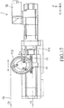
- Extension direction of the screw rod 53 is parallel to the moving direction in the moving path (L2) of the wire guiding roller 512 as shown by the double arrow of FIG. 17 .
- Fixing mechanism of the third rotating motor 52, and the wire guiding roller installation seat 54 of each of the tension adjusting devices 5 are well known in the art, and are therefore not elaborated for the sake of brevity. It is worth mentioning that the moving direction of the wire guiding roller 512 is not limited to be parallel to the second horizontal direction (Y) as long as the sawing wire 91 bears a tension force when slicing the ingot 92 and the tension force is exerted in a direction parallel to the moving path (L2).
- Each of the first rotating motor 441, the second rotating motor 442 and the third rotating motor 52 is a servo motor.
- the third rotating motor 52 is capable of receiving a position signal of the wire guiding roller 512 transmitted by a transducer (not shown). After receiving the position signal, the third rotating motor 52 is operable to transmit a compensation signal to at least one of the first rotating motor 441 and the second rotating motor 442 of the wire supplying and receiving device 4 based on the position of the wire guiding roller 512, so as to fix the tension force of the sawing wire 91 within a certain range. Referring to FIG.
- the third rotating motor 52 outputs a rated torque such that the wire guiding roller 512 bears a driving force (F M ) that is provided by the third rotating motor 52 and that equals two times T1 (i.e., the tension force of the sawing wire 91), allowing the wire guiding roller 512 to be fixed at a certain position.
- F M driving force
- T1 the tension force of the sawing wire 91
- the tension compensation mechanism Since the tension force of the sawing wire 91 is exerted in a direction parallel to the moving path (L2) of the wire guiding roller 512, the tension compensation mechanism has a structure simpler than that of the tension compensation mechanism of Taiwanese Invention Patent No. I488725 , which requires rather complicated formulas. In other words, the compensation mechanism of this disclosure does not have any oblique force components, allowing a simplified calculation. Moreover, the output torque of the third rotating motor 52 is smaller than that of the motor of TW I488725 .
- the present disclosure provides two embodiments of a method for controlling the tension direction of the sawing wire 91 to be parallel to the moving path (L2) of the wire guiding roller 512.
- one of the tension adjusting devices 5 further includes a tension roller 522 that is fixedly sleeved on the output shaft 521 of the third rotating motor 52 and that is rotatable by the third rotating motor 52, a wire guiding roller installation seat 54 that is movable along the second horizontal direction (Y) relative to the corresponding one of the roller installation sections 13 and that is for the wire guiding roller 512 to be rotatably mounted thereto, and a first connecting member 55 that extends along the second horizontal direction (Y) and that interconnects the wire guiding roller installation seat 54 and the first tension roller 522.
- the tension force (T1) of the sawing wire 91 substantially equals to 1/2 of the output torque of the third rotating motor 52 times the radius of the first tension roller 522.
- one of the tension adjusting devices 5 further includes a fourth rotating motor 56 that is disposed on the corresponding one of the roller installation sections 13, that is spaced apart from the third rotating motor 52 and that includes an output shaft 561; a second tension roller 562 that is connected to the output shaft 561 of the fourth rotating motor 56 and that is rotatable by the output shaft 561 of the fourth rotating motor 56, such that the wire guiding roller installation seat 54 that is disposed between the first tension roller 522 and the second tension roller 562; and a second connecting member 57 that interconnects the wire guiding roller installation seat 54 and the second tension roller 562.
- Each of the first and second connecting members 55, 57 extends in a direction parallel to the moving path (L2) of the wire guiding roller 512.
- Each of the first and second connecting members 55, 57 may be a steel cable or a belt.
- the output torque of the third rotating motor 52 is not equal to that of the fourth rotating motor 56.
- the tension force (T1) of the sawing wire 91 substantially equals to 1/2 of the output torque of the third rotating motor 52 times the radius of the first tension roller 522 minus the output torque of the fourth rotating motor 56 times the radius of the second tension roller 562.
- a load cell will be provided to measure the actual tension force of the sawing wire 91 since the tension force of the sawing wire 91 will change each time the sawing wire 91 slices the ingot 92 or passes any of the components of the wire supplying and receiving device 4.
- the actual tension force of the sawing wire 91 can be obtained by measuring the net force provided by the third and fourth rotating motors 52, 56, allowing omission of the load cell.
- each of the first rotating motor 441, the second rotating motor 442, the third rotating motor 52 and the fourth rotating motor 56 is a servo motor.
- Each of the third rotating motor 52 and the fourth rotating motor 56 is operable to transmit a compensation signal to at least one of the first rotating motor 441 and the second rotating motor 442 of the wire supplying and receiving device 4 based on the position of the wire guiding roller 512, so as to fix the tension force of the sawing wire 91 within a certain range, ensuring qualities of wafers made by slicing the ingot 92.
- FIG. 23 is a flow chart of a first embodiment of a method of slicing ingot according to the present disclosure, which includes the following steps.
- a preparing step 1A is provided to prepare a bundle of the sawing wire 91, the roller device 2 for the sawing wire 91 to be wound thereon and for driving movement of the sawing wire 91, a feeding device 3 for the ingot 92 (see FIG. 25 ) to be mounted thereon and for moving the ingot 92 vertically relative to the roller device 2, and two of the wire supplying and receiving devices 4 that are respectively disposed at opposite sides of the roller device 2 and the machine bed 1.
- the feeding device 3 is disposed on the machine bed 1 and includes the feeding seat 31 adapted for the ingot 92 to be mounted thereon.
- the roller device 2 includes two of the main rollers 21 that are spaced apart from each other in the second horizontal direction (Y).
- the wire supplying and receiving devices 4 are respectively defined as a first wire supplying and receiving device 4' and a second wire supplying and receiving device 4".
- a new wire arrangement step 1B includes:
- a first unused wire section rewind step 1C includes converting the second wire supplying and receiving device 4" into the connected state; and rotating the main rollers 21 of the roller device 2 such that a second length of the sawing wire 91 is unwound from the first wire winding unit 42 of the first wire supplying and receiving device 4' and is wound onto the first wire winding unit 42 of the second wire supplying and receiving device 4".
- a slicing step 1D includes moving the feeding device 3 downwardly toward the wire net 911 and rotating the main rollers 21 of the roller device 2 in alternate clockwise and counterclockwise directions to slice the ingot 92 into a plurality of wafers (not shown).
- a third length of the sawing wire 91 is unwound from the first wire winding unit 42 of the second wire supplying and receiving device 4" and is wound onto the first wire winding unit 42 of the first wire supplying and receiving device 4'.
- a finishing slicing step 1E includes, after the step 1D, moving the feeding device 3 and the wafers upwardly, and rotating the main rollers 21 of the roller device 2 to move the sawing wire 91 toward the second wire supplying and receiving device 4" such that a fourth length of the sawing wire 91 for slicing the ingot 91 is unwound from the first wire winding unit 42 of the first wire supplying and receiving device 4' and is wound onto the first wire winding unit 42 of the second wire supplying and receiving device 4" until the wafers are spaced apart from the wire net 911 of the sawing wire 91.
- a recovering used wire section step 1F includes, after the step IE, converting the first wire supplying and receiving device 4' into the disconnected state, and rotating the main rollers 21 of the roller device 2 to move the sawing wire 91 toward the first wire supplying and receiving device 4' such that a fifth length of the sawing wire 91 for slicing the ingot 91 is unwound from the first wire winding unit 42 of the second wire supplying and receiving device 4" and is wound onto the second wire winding unit 43 of the first wire supplying and receiving device 4'.
- step 1F there might be an unused section of sawing wire 91 on the first wire winding unit 42 of the second wire supplying and receiving device 4" or no unused section of the sawing wire 91 on the first wire winding unit 42 of the second wire supplying and receiving device 4". Therefore, there are two follow-up steps after step 1F respectively for these two situations.
- a first supplementing step 1G includes after the step 1F and when there is no unused section of the sawing wire 91 on the first wire winding unit 42 of the second wire supplying and receiving device 4", converting the first wire supplying and receiving device 4' into the connected state, converting the second wire supplying and receiving device 4" into the disconnected state, and rotating the main rollers 21 such that the sixth length of the sawing wire 91 is unwound from the second wire winding unit 43 of the second wire supplying and receiving device 4" and is wound onto the first wire winding unit 42 of the first wire supplying and receiving device 4'.
- a second supplementing step 1G' includes after the step 1F and when there is unused section of the sawing wire 91 on the first wire winding unit 42 of the second wire supplying and receiving device 4", converting the first wire supplying and receiving device 4' into the connected state, rotating the main rollers 21 of the roller device 2 until there is no unused section of the sawing wire 91 left on the first wire winding unit 42 of the second wire supplying and receiving device 4", converting the second wire supplying and receiving device 4" into the disconnected state, and rotating the main rollers 21 of the roller device 2 such that the seventh length of the sawing wire 91 is unwound from the second wire winding unit 43 of the second wire supplying and receiving device 4" and is wound onto the first wire winding unit 42 of the first wire supplying and receiving device 4'.
- a second unused wire rewind step 1H includes, after one of the steps 1G or 1G', converting the second wire supplying and receiving device 4" into the connected state, and rotating the main rollers 21 of the roller device 2 such that an eighth length of the sawing wire 91 that is used for performing step 1D is unwound from the first wire winding unit 42 of the first wire supplying and receiving device 4' and is wound onto the first wire winding unit 42 of the second wire supplying and receiving device 4".
- the ingot slicing wire saw 100 is ready for performing another slicing action.
- the abovementioned method effectively winds used and unused sections of the sawing wires 91 respectively on the first and second wire winding units 42, 43 of the first wire supplying and receiving device 4' and the second wire supplying and receiving device 4", thereby alleviating the abovementioned wire wear issue.
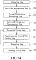
- FIG. 34 is a flow chart of a second embodiment of the method of slicing ingot according to the present disclosure, which includes the following steps.
- steps 2A and 2B are identical to the steps 1A and 1B, respectively, and description thereof is omitted for the sake of brevity.
- a forward slicing and recovery step 2C includes moving the feeding device 3 downwardly toward the wire net 911 and rotating the main rollers 21 of the roller device 2 to move the sawing wire 91 toward the first wire supplying and receiving device 4', such that a first length of the sawing wire 91 is unwound from the second wire winding unit 43 of the second wire supplying and receiving device 4" and is wound onto the second wire winding unit 43 of the first wire supplying and receiving device 4', so that the wire net 911 is moved forwardly to slice the ingot 92.
- a rearward slicing and non-recovery step 2D includes converting the first wire supplying and receiving device 4' into the connected state, and rotating the main rollers 21 of the roller device 2 to move the sawing wire 91 toward the first wire supplying and receiving device 4', such that a second length of the sawing wire 91 is unwound from the second wire winding unit 43 of the second wire supplying and receiving device 4" and is wound onto the first wire winding unit 42 of the first wire supplying and receiving device 4', so that the wire net 911 is moved forwardly to slice the ingot 92.
- a rearward slicing step 2E includes converting the second wire supplying and receiving device 4" into the connected state, and rotating the two main rollers 21 of the roller device 2 to move the sawing wire 91 toward the second wire supplying and receiving device 4" such that the wire net 911 is moved rearwardly to slice the ingot 92 and a third length of the sawing wire 91 is unwound from the first wire winding unit 42 of the first wire supplying and receiving device 4' and is wound onto the first wire winding unit 42 of the second wire supplying and receiving device 4", and converting the first wire supplying and receiving device 4' into the disconnected state.
- a supplementing unused wire section step 2F includes rotating the main rollers 21 of the roller device 2 to move the sawing wire 91 toward the first wire supplying and receiving device 4', such that the wire net 911 slices the ingot 92 and a fourth length of the sawing wire 91 is unwound from the first wire winding unit 42 of the second wire supplying and receiving device 4" and is wound onto the second wire winding unit 43 of the first wire supplying and receiving device 4' (see FIG. 39 ), converting the first wire supplying and receiving device 4' into the connected state (see FIG. 40 ), converting the second wire supplying and receiving device 4" into the disconnected state (see FIG.
- a repeating step 2G includes repeating steps 2E and 2F until the ingot 92 is sliced into the wafers.
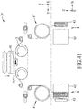
- a finishing slicing step 2H includes moving the feeding device 3 and the wafers upwardly and away from the wire net 911 of the sawing wire 91, rotating the main rollers 21 of the roller device 2 to move the sawing wire 91 toward the second wire supplying and receiving device 4" such that a sixth length of the sawing wire 91 is unwound from the first wire winding unit 42 of the first wire supplying and receiving device 4' and is wound onto the second wire winding unit 43 of the second wire supplying and receiving device 4" (see FIG. 42 ), converting the first wire supplying and receiving device 4' into the disconnected state (see FIG.
- the second embodiment of the method of slicing ingot according to the present disclosure collects the used section of the sawing wire 91 on the second wire winding unit 43 of the second wire supplying and receiving device 4". Therefore, if wire breakage (especially breakage of the used section of the sawing wire 91) happens, a user only needs to take the used sawing wire 91 from the second wire winding unit 43 of the first wire supplying and receiving device 4', followed by fixing an end of the unused sawing wire 91 to the second wire winding unit 43 of the first wire supplying and receiving device 4', which is a simplified and cost-effective method.
- the second embodiment of the method of slicing ingot according to the present disclosure also includes less steps of arranging unused sections and used sections of the sawing wire 91 on the first and second wire supplying and receiving devices 4', 4", thereby improving slicing efficiency.
- the ingot slicing wire saw 100 and the method of slicing ingot according to the present disclosure both contribute to reducing total length of sawing wire required for cutting, improving sliced wafer quality, shortening process time, thereby improving slicing efficiency and lowering costs.
Abstract
Description
- The disclosure relates to a wire supplying and receiving device, an ingot slicing wire saw including the same, and a method of slicing ingot.
- Conventionally, ingots are sliced by metal wires carrying cutting slurry to form a plurality of wafers. The cutting slurry is made by mixing particles and liquid or oil. In response to rising environmental concerns and rising wafer demands, the abovementioned slicing technique is gradually abandoned. Nowadays, wire saws mounted with abrasive particles (e.g., diamond particles) are used for slicing the ingots.
- In practical application, the wire saws are wound around two main rollers of an ingot slicing apparatus, and around a first wire winding roller and a second wire winding roller that are located opposite to each other with respect to the main rollers to form a wire net between the main rollers. When the ingot is moved into a space between the main rollers, the wire net slices the ingot. The sawing wires are either moved unidirectionally from the first wire winding roller onto the second wire winding roller or moved reciprocally between the main rollers. The latter is more economic in terms of sawing wire usage, and is widely used. However, since the sawing wires are coiled around the first and second wire winding rollers, when portions of the sawing wires are being wound on or leaving the rollers, they move relative to the remaining portions of the sawing wires coiled thereunder, resulting in undesirable wear. Moreover, the degree of wear of the abrasive particles should be taken into account when performing slicing action.
- Taiwanese Invention Patent Application No.
201501844 A TW 201501844 A - Therefore, an object of the disclosure is to provide a wire supplying and receiving device for a wire saw, an ingot slicing wire saw including the same, and a method of slicing ingot that can alleviate at least one of the drawbacks of the prior art.
- According to a first aspect of the present disclosure, the wire supplying and receiving device for a wire saw includes a moving unit, a first wire winding unit and a second wire winding unit.
- The moving unit includes a rail that extends along a first horizontal direction. The first wire winding unit is disposed on the rail and is rotatable about an axis parallel to the first horizontal direction. The second wire winding unit is disposed on the rail and is rotatable about the axis. At least one of the first wire winding unit and the second wire winding unit is movable on the rail along the first horizontal direction. The wire supplying and receiving device is convertible between a connected state, where the first and second wire winding units are adjacent to each other, and a disconnected state, where the first wire winding unit and the second wire winding unit are spaced apart from each other in the first horizontal direction.
- According to a second aspect of the present disclosure, the ingot slicing wire saw is adapted to be mounted with a sawing wire for slicing an ingot.
- The ingot slicing wire saw includes a machine bed, a roller device, a feeding device and two of the aforementioned wire supplying and receiving devices.
- The roller device includes two main rollers rotatably connected to the machine bed and horizontally spaced apart from each other. The feeding device is disposed on the machine bed and above the roller device, and includes a feeding seat adapted for the ingot to be mounted thereon and operable to carry the ingot to move between the main rollers. The wire supplying and receiving devices are respectively disposed at opposite sides of the machine bed. The sawing wire is wound on the wire supplying and receiving devices and the main rollers of the roller device to form a wire net having a plurality of sawing sections spanning a space between the main rollers and adapted for slicing the ingot.
- According to a third aspect of the present, disclosure , the method for slicing an ingot includes:
- (A) preparing a bundle of sawing wire, a roller device for the sawing wire to be wound thereon and for driving movement of the sawing wire, a feeding device for the ingot to be mounted thereon and for moving the ingot vertically relative to the roller device, and two of the wire supplying and receiving devices as claimed in
claim 1 that are respectively disposed at opposite sides of the roller device, wherein the roller device includes two rollers that are spaced apart from each other in a second horizontal direction perpendicular to the first horizontal direction, and the wire supplying and receiving devices are respectively defined as a first wire supplying and receiving device and a second wire supplying and receiving device; - (B) converting each of the first and second wire supplying and receiving devices into the disconnected state, winding the bundle of the sawing wire onto the second wire winding unit of the second wire supplying and receiving device, and winding the sawing wire on the rollers to form a wire net between the rollers, followed by fastening an end of the sawing wire to the second wire winding unit of the first wire supplying and receiving device, followed by converting the first wire supplying and receiving device into the connected state, followed by rotating the rollers of the roller device such that a first length of the sawing wire is unwound from the second wire winding unit of the second wire supplying and receiving device and is wound onto the first wire winding unit of the first wire supplying and receiving device, the first length of the sawing wire being for slicing the ingot;
- (C) converting the second wire supplying and receiving device into the connected state, followed by rotating the rollers of the roller device such that a second length of the sawing wire is unwound from the first wire winding unit of the first wire supplying and receiving device and is wound onto the first wire winding unit of the second wire supplying and receiving device; and
- (D) moving the feeding device downwardly toward the wire net and rotating the rollers of the roller device in alternate clockwise and counterclockwise directions to slice the ingot into a plurality of wafers, a third length of the sawing wire is unwound from the first wire winding unit of the second wire supplying and receiving device and is wound onto the first wire winding unit of the first wire supplying and receiving device.
- Other features and advantages of the disclosure will become apparent in the following detailed description of the embodiments with reference to the accompanying drawings, of which:
-
FIG. 1 is a perspective view of an embodiment of an ingot slicing wire saw according to the present disclosure; -
FIG. 2 is a side view of the embodiment; -
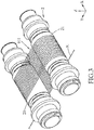
FIG. 3 is a schematic view showing a sawing wire wound on two main rollers of a roller device of the embodiment; -
FIG. 4 is a schematic view showing the sawing wire being installed on the embodiment; -
FIG. 5 is a schematic view showing an alternative of the embodiment; -
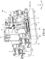
FIG. 6 is a fragmentary perspective view of the embodiment; -
FIG. 7 is a fragmentary enlarged view of the embodiment, illustrating one of wire supplying and receiving devices of the embodiment; -
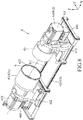
FIG. 8 is a perspective view of the one of the wire supplying and receiving devices of the embodiment; -
FIG. 9 is a perspective view of a first wire winding unit of the one of the wire supplying and receiving devices of the embodiment; -
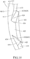
FIG. 10 is a fragmentary perspective view of a wire guiding seat of the one of the wire supplying and receiving devices of the embodiment; -
FIG. 11 is a side view showing the one of the wire supplying and receiving devices of the embodiment being in a disconnected state, where the first wire winding unit and a second wire winding unit of the one of the wire supplying and receiving devices of the embodiment are separated from each other; -
FIG. 12 is a side view showing the one of the wire supplying and receiving devices of the embodiment being in a connected state, where the second wire winding unit engages the first wire winding unit; -
FIG. 13 is a partially sectional view of the one of the wire supplying and receiving devices in the connected state; -
FIG. 14 is a schematic view showing an alternative of the one of the wire supplying and receiving devices, in which the first and second wire winding units are both solid; -
FIG. 15 is a schematic view of another alternative of the embodiment; -
FIG. 16 is a schematic view showing the one of the wire supplying and receiving devices being provided with a wire guiding member; -
FIG. 17 is a schematic view showing one of tension adjusting devices of the embodiment; -
FIG. 18 is a schematic view showing the tension adjusting devices operating in cooperation with the wire supplying and receiving devices of the embodiment; -
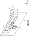
FIG. 19 is a perspective view showing a first alternative of the one of the tension adjusting devices of the embodiment; -
FIG. 20 is a schematic view of the first alternative of the one of the tension adjusting devices of the embodiment; -
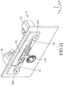
FIG. 21 is a perspective view showing a second alternative of the one of the tension adjusting devices of the embodiment; -
FIG. 22 is a schematic view of the second alternative of the one of the tension adjusting devices of the embodiment; -
FIG. 23 is a flow chart of a first embodiment of a method of slicing ingot according to the present disclosure; -
FIG. 24 is a schematic view showing astep 1A of the first embodiment of the method; -
FIGS. 25 and26 are schematicviews showing step 1B of the first embodiment of the method; -
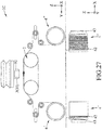
FIG. 27 is a schematicview showing step 1C of the first embodiment of the method; -
FIG. 28 is a schematicview showing step 1D of the first embodiment of the method; -
FIG. 29 is a schematicview showing step 1E of the first embodiment of the method; -
FIG. 30 is a schematicview showing step 1F of the first embodiment of the method; -
FIG. 31 is a schematicview showing step 1G of the first embodiment of the method; -
FIG. 32 is a schematic view showing an alternative of thestep 1G (step 1G') of the first embodiment of the method; -
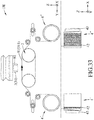
FIG. 33 is a schematicview showing step 1H of the first embodiment of the method; -
FIG. 34 is a flow chart of a second embodiment of the method of slicing ingot according to the present disclosure; -
FIG. 35 is a schematicview showing step 2C of the second embodiment of the method; -
FIG. 36 is a schematicview showing step 2D of the second embodiment of the method; -
FIGS. 37 and38 are schematicviews showing step 2E of the second embodiment of the method; -
FIGS. 39 to 41 are schematicviews showing step 2F of the second embodiment of the method; and -
FIGS. 42 and43 are schematicviews showing step 2H of the second embodiment of the method. - Before the disclosure is described in greater detail, it should be noted that where considered appropriate, reference numerals or terminal portions of reference numerals have been repeated among the figures to indicate corresponding or analogous elements, which may optionally have similar characteristics.
- Referring to
FIGs 1 to 4 , an embodiment of an ingot slicing wire saw 100 is adapted to be mounted with asawing wire 91 for slicing aningot 92. The ingot slicing wire saw 100 includes amachine bed 1, aroller device 2, afeeding device 3, two wire supplying and receivingdevices 4, and twotension adjusting devices 5. A three-dimensional coordinate system having a first horizontal direction (X), a second horizontal direction (Y) and a height direction (Z) that are perpendicular to each other is defined for illustration purpose. - Referring to
FIGS. 1 ,2 and5 , themachine bed 1 includes abase section 11, a slicingseat section 12 and tworoller installation sections 13. The slicingseat section 12 is disposed on thebase section 11, extends upwardly along the height direction (Z), and is mounted with theroller device 2. Theroller installation sections 13 are respectively disposed at opposite sides of the slicingseat section 12 along the second horizontal direction (Y). - The
roller device 2 includes twomain rollers 21 rotatably connected to themachine bed 1 and horizontally spaced apart from each other. Thesawing wire 91 is wound on the wire supplying and receivingdevices 4 and themain rollers 21 of theroller device 2 to form a wire net 911 (seeFIG. 3 ) having a plurality of sawing sections spanning a space between themain rollers 21 and adapted for slicing theingot 92. When the ingot slicing wire saw 100 is used for slicing theingot 92, the sawing sections of thewire net 911 are moved reciprocally in the second horizontal direction (Y) by themain rollers 21 to slice theingot 92. - Referring to
FIGS. 1 ,2 and4 , thefeeding device 3 is disposed on themachine bed 1 and above theroller device 2, and includes a feedingseat 31 and a brokenwafer receiving box 32. The feedingseat 31 is adapted for theingot 92 to be mounted thereon and is operable to carry theingot 92 to move between themain rollers 21. The brokenwafer receiving box 32 is located under the feedingseat 31, and is used for receiving broken pieces of theingot 92. - The wire supplying and receiving
devices 4 are respectively located at opposite sides of themachine bed 1. As shown inFIG. 4 , thesawing wire 91 sequentially extends on one of the wire supplying and receivingdevices 4, theroller device 2 and the other one of the wire supplying and receivingdevices 4. - Referring to
FIG. 5 , in an alternative of the embodiment, theroller device 2 further includes twoauxiliary rollers 22 that are disposed below thefeeding device 3 and that are disposed between themain rollers 21. Lowermost side of each of theauxiliary rollers 22 is not higher than uppermost side of each of themain rollers 21. Diameter of each of theauxiliary rollers 22 is smaller than one-half of diameter of each of themain rollers 21. In this alternative of the embodiment, thesawing wire 91 is wound on the wire supplying and receivingdevices 4, themain rollers 21 and theauxiliary rollers 22 to form thewire net 911 having the sawing sections spanning a space between theauxiliary rollers 22 and adapted for slicing theingot 92. - It is worth mentioning that the synergy between the wire supplying and receiving
devices 4 and theauxiliary rollers 22 contributes to the quality and stability of thesawing wire 91 during slicing. Moreover, the relative position and size between themain rollers 21 and theauxiliary rollers 22 also contributes to the quality and stability of thesawing wire 91 during slicing. Such configuration allows the use of sawingwire 91 with smaller diameter (such as 40∼60 micrometer), and reduces the possibility of wire breakage, especially in the case of using the hollowauxiliary rollers 22. - Referring to
FIGS. 6 to 8 , each of the wire supplying and receivingdevices 4 includes a movingunit 41, a firstwire winding unit 42, a secondwire winding unit 43 and a drivingunit 44. - The structures of only one of the wire supplying and receiving
devices 4 is described in detail hereinafter for the sake of brevity. - The wire supplying and receiving
device 4 includes tworails 411, a first movingseat 412 and a second movingseat 413. Each of therails 411 extends along the first horizontal direction (X). The first and second movingseats rails 411. In certain embodiments, the wire supplying and receivingdevice 4 may include only onerail 411, as long as the first and second movingseats rail 411 can move along the first horizontal direction (X). In certain embodiments, therails 411 may be non-continuous, as long as there are rails provided in the movement range of the first and second movingseats wire winding unit 42 and the secondwire winding unit 43 are rotatably and respectively mounted to the first movingseat 412 and the second movingseat 413. Specifically, each of the firstwire winding unit 42 and the secondwire winding unit 43 extends along the first horizontal direction (X), and is rotatable about an axis (L1) parallel to the first horizontal direction (X). - Referring to
FIGS. 6 ,8 and9 , the firstwire winding unit 42 of the wire supplying and receivingdevice 4 includes a first rotatingmember 421 and a wire guiding seat. 6. The firstrotating member 421 is rotatably mounted to the first movingseat 412. Thewire guiding seat 6 is detachably mounted to the first rotatingmember 421. - The first
rotating member 421 is hollow and has anopen end 422. Thewire guiding seat 6 is detachably disposed at theopen end 422 of the first rotatingmember 421, and includes a surroundingwall 61 that extends about the axis (L1), and at least two angularly equidistantwire guiding members 62 that are disposed on the surroundingwall 61. - Referring to
FIGS. 9 and10 , the surroundingwall 61 of thewire guiding seat 6 has afirst side portion 611 that is connected to the end of the first rotatingmember 421, and asecond side portion 612 that is opposite to thefirst side portion 611 and that is used for thewire guiding members 62 to be disposed thereon. Thesecond side portion 612 of the surroundingwall 61 of thewire guiding seat 6 has a plurality of connectingsurfaces 613, and a plurality of extendingsurfaces 614. Each of the connectingsurfaces 613 is connected between adjacent two of thewire guiding members 62. The number of the extendingsurfaces 614 is twice the number of the connecting surfaces 613. Each of the extendingsurfaces 614 is connected to a corresponding one of the connecting surfaces 613. - Each of the
wire guiding members 62 has aninner side surface 621 that is proximate to the axis (L1), two guidingsurfaces 622 that respectively extend from opposite ends of theinner side surface 621 away from the axis (L1) and toward each other, and anouter side surface 623 that interconnects the guidingsurfaces 622 and that is spaced apart from theinner side surface 621. Each of the guiding surfaces 622 is of a trapezoid shape, and has awide base side 624 that is connected to theouter side surface 623 and anarrow base side 625 that is connected to theinner side surface 621. In this embodiment, each of the extendingsurfaces 614 cooperates with an adjacent one of the guidingsurfaces 622 of a corresponding one of thewire guiding members 62 to define awire guiding grooves 626 adapted for extension of thesawing wire 91 therethrough. - Referring to
FIGS. 7 ,8 and11 , the secondwire winding unit 43 of the wire supplying and receivingdevice 4 is disposed on therails 411, extends along the first horizontal direction (X), and is rotatable about the axis (L1). The secondwire winding unit 43 includes a secondrotating member 431 that is rotatably mounted to the second movingseat 413, and extends along the first horizontal direction (X) . Theopen end 422 of the first rotatingmember 421 is used for the second rotatingmember 431 to extend therethrough. - Referring to
FIGS. 11 to 13 , in this embodiment, at least one of the firstwire winding unit 42 and the secondwire winding unit 43 is movable on therails 411 along the first horizontal direction (X). The firstwire winding unit 42 and the secondwire winding unit 43 are respectively carried by the first and second movingseats rails 411 such that the wire supplying and receivingdevice 4 is convertible between a connected state (seeFIG. 12 ) and a disconnected state (seeFIG. 11 ). - In the connected state, the first moving
seat 412 and the second movingseat 413 are adjacent to each other. When the wire supplying and receivingdevice 4 is converted from the disconnected state into the connected state, the first and second movingseats device 4 is converted from the connected state into the disconnected state, the first movingseat 412 and the second movingseat 413 are moved away from each other. - Referring to
FIGS. 12 and13 , in the connected state, aninner surrounding surface 423 of the first rotatingmember 421 is spaced apart from anouter surrounding surface 432 of the second rotatingmember 431 at a distance (D) (seeFIG. 13 ). Also in the connected state, an end of the first rotatingmember 421 is sleeved on an end of the second rotating member 431 (i.e., the first rotatingmember 421 surrounds the second rotating member 431). Referring toFIGS. 11 and13 , it is worth mentioning that thewire guiding members 62 facilitates thesawing wire 91 to be smoothly wound on both the first and secondwire winding units device 4 is in the connected state, thereby reducing the risk of wire breakage. - Referring to
FIG. 14 , in an alternative of the wire supplying and receivingdevice 4, the first and secondrotating members rotating members device 4 is in the connected state. It is worth mentioning that thesawing wire 91 is first wound on the second rotatingmember 431 having a smaller diameter than the first rotatingmember 421. During winding of thesawing wire 91 around the second rotatingmember 431, when the inner diameter of the outmost coil of thesawing wire 91 abutting against an end surface of the first rotatingmember 421 is increased to be approximate to the diameter of the outer surroundingsurface 421 of the first rotatingmember 421, thesawing wire 91 is wound onto the first rotatingmember 421, thereby reducing the possibility of wire breakage. In certain embodiment, it is worth mentioning that at least one of the first rotatingmember 421 and the second rotatingmember 431 may be hollow, and thesawing wire 91 may be wound onto the first rotatingmember 421 with the assistance of thewire guiding members 62. - Referring to
FIG. 15 , in another alternative of the embodiment, the secondwire winding unit 43 is fixed on therails 411. Apulley unit 51 is provided, and includes an idler 511 that is adjacent to the secondwire winding unit 43 and that is movable along the first horizontal direction (X) to control thesawing wire 91 to be wound on the first and secondwire winding units - Referring to
FIG. 16 , alternatively, there may be only onewire guiding member 62 as long as thewire guiding member 62 is disposed at theopen end 422 of the first rotatingmember 421, extends along the first horizontal direction (X), and is capable of guiding thesawing wire 91 from the secondwire winding unit 43 toward the firstwire winding unit 42. In certain embodiments, thewire guiding member 62 is a screw. - Referring to
FIGS. 7 and8 , the drivingunit 44 of the wire supplying and receivingdevice 4 includes a firstrotating motor 441 for driving rotation of the firstwire winding unit 42, a secondrotating motor 442 for driving rotation of the secondwire winding unit 43, a first movingmotor 443 for driving movement of the first movingseat 412 relative to the second movingseat 413, and a second movingmotor 444 for driving movement of the second movingseat 413 relative to the first movingseat 412. - Referring to
FIGS. 1 ,2 and4 , thetension adjusting devices 5 are respectively located at opposite sides of theroller device 2 and respectively disposed on theroller installation sections 13. Each of thetension adjusting devices 5 includes thepulley unit 51 that is disposed between theroller device 2 and a corresponding wire supplying and receivingdevice 4 and that is adapted for adjusting extending direction of thesawing wire 91. In this embodiment, thepulley unit 51 includes a plurality of theidlers 511 for adjusting extending direction of thesawing wire 91. - Referring to
FIGS. 2 ,4 and17 , one of theidlers 511 is defined as awire guiding roller 512 that is configured to be movable along a moving path (L2) parallel to the second horizontal direction (Y), and the remainingidlers 511 are rotatable and not movable. In this embodiment, each of thetension adjusting devices 5 further includes a thirdrotating motor 52 that is disposed on a corresponding one of theroller installation sections 13 and that includes anoutput shaft 521, ascrew rod 53 that is connected to theoutput shaft 521 of the thirdrotating motor 52 and that is rotatable by the thirdrotating motor 52, and a wire guidingroller installation seat 54 that is threadedly connected to thescrew rod 53 such that rotation of theoutput shaft 521 is converted into movement of the wire guidingroller installation seat 54. Extension direction of thescrew rod 53 is parallel to the moving direction in the moving path (L2) of thewire guiding roller 512 as shown by the double arrow ofFIG. 17 . Fixing mechanism of the thirdrotating motor 52, and the wire guidingroller installation seat 54 of each of thetension adjusting devices 5 are well known in the art, and are therefore not elaborated for the sake of brevity. It is worth mentioning that the moving direction of thewire guiding roller 512 is not limited to be parallel to the second horizontal direction (Y) as long as thesawing wire 91 bears a tension force when slicing theingot 92 and the tension force is exerted in a direction parallel to the moving path (L2). - Each of the first
rotating motor 441, the secondrotating motor 442 and the thirdrotating motor 52 is a servo motor. The thirdrotating motor 52 is capable of receiving a position signal of thewire guiding roller 512 transmitted by a transducer (not shown). After receiving the position signal, the thirdrotating motor 52 is operable to transmit a compensation signal to at least one of the firstrotating motor 441 and the secondrotating motor 442 of the wire supplying and receivingdevice 4 based on the position of thewire guiding roller 512, so as to fix the tension force of thesawing wire 91 within a certain range. Referring toFIG. 17 , the thirdrotating motor 52 outputs a rated torque such that thewire guiding roller 512 bears a driving force (FM) that is provided by the thirdrotating motor 52 and that equals two times T1 (i.e., the tension force of the sawing wire 91), allowing thewire guiding roller 512 to be fixed at a certain position. When thewire guiding roller 512 moves along the second horizontal direction (Y) (i.e., the tension force of thesawing wire 91 changes), the rated torque is changed accordingly based on the abovementioned compensation mechanism, thereby maintaining the slicing capacity of thesawing wire 91. - Since the tension force of the
sawing wire 91 is exerted in a direction parallel to the moving path (L2) of thewire guiding roller 512, the tension compensation mechanism has a structure simpler than that of the tension compensation mechanism of Taiwanese Invention Patent No.I488725 rotating motor 52 is smaller than that of the motor ofTW I488725 - The present disclosure provides two embodiments of a method for controlling the tension direction of the
sawing wire 91 to be parallel to the moving path (L2) of thewire guiding roller 512. - Referring to
FIGS. 4 ,19 and20 , in a first embodiment of the method, one of thetension adjusting devices 5 further includes atension roller 522 that is fixedly sleeved on theoutput shaft 521 of the thirdrotating motor 52 and that is rotatable by the thirdrotating motor 52, a wire guidingroller installation seat 54 that is movable along the second horizontal direction (Y) relative to the corresponding one of theroller installation sections 13 and that is for thewire guiding roller 512 to be rotatably mounted thereto, and a first connectingmember 55 that extends along the second horizontal direction (Y) and that interconnects the wire guidingroller installation seat 54 and thefirst tension roller 522. In this embodiment, the tension force (T1) of thesawing wire 91 substantially equals to 1/2 of the output torque of the thirdrotating motor 52 times the radius of thefirst tension roller 522. - Referring to
FIGS . 4 ,21 and22 , in a second embodiment of the method, one of thetension adjusting devices 5 further includes a fourthrotating motor 56 that is disposed on the corresponding one of theroller installation sections 13, that is spaced apart from the thirdrotating motor 52 and that includes anoutput shaft 561; asecond tension roller 562 that is connected to theoutput shaft 561 of the fourthrotating motor 56 and that is rotatable by theoutput shaft 561 of the fourthrotating motor 56, such that the wire guidingroller installation seat 54 that is disposed between thefirst tension roller 522 and thesecond tension roller 562; and a second connectingmember 57 that interconnects the wire guidingroller installation seat 54 and thesecond tension roller 562. Each of the first and second connectingmembers wire guiding roller 512. Each of the first and second connectingmembers rotating motor 52 is not equal to that of the fourthrotating motor 56. The tension force (T1) of thesawing wire 91 substantially equals to 1/2 of the output torque of the thirdrotating motor 52 times the radius of thefirst tension roller 522 minus the output torque of the fourthrotating motor 56 times the radius of thesecond tension roller 562. - It is worth mentioning that, in practice, a load cell will be provided to measure the actual tension force of the
sawing wire 91 since the tension force of thesawing wire 91 will change each time thesawing wire 91 slices theingot 92 or passes any of the components of the wire supplying and receivingdevice 4. In this embodiment, since there are two motors provided (i.e., the thirdrotating motor 52 and the fourth rotating motor 56), the actual tension force of thesawing wire 91 can be obtained by measuring the net force provided by the third and fourthrotating motors - In this embodiment, each of the first
rotating motor 441, the secondrotating motor 442, the thirdrotating motor 52 and the fourthrotating motor 56 is a servo motor. Each of the thirdrotating motor 52 and the fourthrotating motor 56 is operable to transmit a compensation signal to at least one of the firstrotating motor 441 and the secondrotating motor 442 of the wire supplying and receivingdevice 4 based on the position of thewire guiding roller 512, so as to fix the tension force of thesawing wire 91 within a certain range, ensuring qualities of wafers made by slicing theingot 92. -
FIG. 23 is a flow chart of a first embodiment of a method of slicing ingot according to the present disclosure, which includes the following steps. - Referring to
FIGS. 23 and24 , a preparingstep 1A is provided to prepare a bundle of thesawing wire 91, theroller device 2 for thesawing wire 91 to be wound thereon and for driving movement of thesawing wire 91, afeeding device 3 for the ingot 92 (seeFIG. 25 ) to be mounted thereon and for moving theingot 92 vertically relative to theroller device 2, and two of the wire supplying and receivingdevices 4 that are respectively disposed at opposite sides of theroller device 2 and themachine bed 1. Thefeeding device 3 is disposed on themachine bed 1 and includes the feedingseat 31 adapted for theingot 92 to be mounted thereon. Theroller device 2 includes two of themain rollers 21 that are spaced apart from each other in the second horizontal direction (Y). The wire supplying and receivingdevices 4 are respectively defined as a first wire supplying and receiving device 4' and a second wire supplying and receivingdevice 4". - Referring to
FIGS. 23 ,25 and26 , a newwire arrangement step 1B includes: - converting each of the first and second wire supplying and receiving
devices 4', 4" into the disconnected state (seeFIG. 25 ); - winding the bundle of the
sawing wire 91 onto the secondwire winding unit 43 of the second wire supplying and receivingdevice 4" (seeFIG. 25 ); - winding the
sawing wire 91 on themain rollers 21 to form the wire net 911 between the main rollers 21 (seeFIG. 25 ); - fastening an end of the
sawing wire 91 to the secondwire winding unit 43 of the first wire supplying and receiving device 4' (seeFIG. 25 ); - converting the first wire supplying and receiving device 4' into the connected state (see
FIG. 26 ); and - rotating the
main rollers 21 of theroller device 2 such that a first length of thesawing wire 91 is unwound from the secondwire winding unit 43 of the second wire supplying and receivingdevice 4" and is wound onto the firstwire winding unit 42 of the first wire supplying and receiving device 4' (seeFIG. 26 ). The first length of thesawing wire 91 is for slicing theingot 92. - Referring to
FIGS. 23 and27 , a first unused wiresection rewind step 1C includes converting the second wire supplying and receivingdevice 4" into the connected state; and rotating themain rollers 21 of theroller device 2 such that a second length of thesawing wire 91 is unwound from the firstwire winding unit 42 of the first wire supplying and receiving device 4' and is wound onto the firstwire winding unit 42 of the second wire supplying and receivingdevice 4". - Referring to
FIGS. 23 and28 , a slicingstep 1D includes moving thefeeding device 3 downwardly toward thewire net 911 and rotating themain rollers 21 of theroller device 2 in alternate clockwise and counterclockwise directions to slice theingot 92 into a plurality of wafers (not shown). Each time each of themain rollers 21 is rotated reciprocally, a third length of thesawing wire 91 is unwound from the firstwire winding unit 42 of the second wire supplying and receivingdevice 4" and is wound onto the firstwire winding unit 42 of the first wire supplying and receiving device 4'. - Referring to
FIGS. 23 and29 , afinishing slicing step 1E includes, after thestep 1D, moving thefeeding device 3 and the wafers upwardly, and rotating themain rollers 21 of theroller device 2 to move thesawing wire 91 toward the second wire supplying and receivingdevice 4" such that a fourth length of thesawing wire 91 for slicing theingot 91 is unwound from the firstwire winding unit 42 of the first wire supplying and receiving device 4' and is wound onto the firstwire winding unit 42 of the second wire supplying and receivingdevice 4" until the wafers are spaced apart from thewire net 911 of thesawing wire 91. - Referring to
FIGS. 23 and30 , a recovering usedwire section step 1F includes, after the step IE, converting the first wire supplying and receiving device 4' into the disconnected state, and rotating themain rollers 21 of theroller device 2 to move thesawing wire 91 toward the first wire supplying and receiving device 4' such that a fifth length of thesawing wire 91 for slicing theingot 91 is unwound from the firstwire winding unit 42 of the second wire supplying and receivingdevice 4" and is wound onto the secondwire winding unit 43 of the first wire supplying and receiving device 4'. - After
step 1F, there might be an unused section of sawingwire 91 on the firstwire winding unit 42 of the second wire supplying and receivingdevice 4" or no unused section of thesawing wire 91 on the firstwire winding unit 42 of the second wire supplying and receivingdevice 4". Therefore, there are two follow-up steps afterstep 1F respectively for these two situations. - Referring to
FIGS. 23 and31 , a first supplementingstep 1G includes after thestep 1F and when there is no unused section of thesawing wire 91 on the firstwire winding unit 42 of the second wire supplying and receivingdevice 4", converting the first wire supplying and receiving device 4' into the connected state, converting the second wire supplying and receivingdevice 4" into the disconnected state, and rotating themain rollers 21 such that the sixth length of thesawing wire 91 is unwound from the secondwire winding unit 43 of the second wire supplying and receivingdevice 4" and is wound onto the firstwire winding unit 42 of the first wire supplying and receiving device 4'. - Referring to
FIGS. 23 and32 , alternatively, a second supplementingstep 1G' includes after thestep 1F and when there is unused section of thesawing wire 91 on the firstwire winding unit 42 of the second wire supplying and receivingdevice 4", converting the first wire supplying and receiving device 4' into the connected state, rotating themain rollers 21 of theroller device 2 until there is no unused section of thesawing wire 91 left on the firstwire winding unit 42 of the second wire supplying and receivingdevice 4", converting the second wire supplying and receivingdevice 4" into the disconnected state, and rotating themain rollers 21 of theroller device 2 such that the seventh length of thesawing wire 91 is unwound from the secondwire winding unit 43 of the second wire supplying and receivingdevice 4" and is wound onto the firstwire winding unit 42 of the first wire supplying and receiving device 4'. - Referring to
FIGS. 23 and33 , a second unusedwire rewind step 1H includes, after one of thesteps device 4" into the connected state, and rotating themain rollers 21 of theroller device 2 such that an eighth length of thesawing wire 91 that is used for performingstep 1D is unwound from the firstwire winding unit 42 of the first wire supplying and receiving device 4' and is wound onto the firstwire winding unit 42 of the second wire supplying and receivingdevice 4". - Afterwards, the ingot slicing wire saw 100 is ready for performing another slicing action.
- It is worth mentioning that the abovementioned method effectively winds used and unused sections of the sawing
wires 91 respectively on the first and secondwire winding units device 4", thereby alleviating the abovementioned wire wear issue. -
FIG. 34 is a flow chart of a second embodiment of the method of slicing ingot according to the present disclosure, which includes the following steps. - Referring to
FIG.34 ,steps 2A and 2B are identical to thesteps - Referring to
FIGS. 34 and35 , a forward slicing andrecovery step 2C includes moving thefeeding device 3 downwardly toward thewire net 911 and rotating themain rollers 21 of theroller device 2 to move thesawing wire 91 toward the first wire supplying and receiving device 4', such that a first length of thesawing wire 91 is unwound from the secondwire winding unit 43 of the second wire supplying and receivingdevice 4" and is wound onto the secondwire winding unit 43 of the first wire supplying and receiving device 4', so that thewire net 911 is moved forwardly to slice theingot 92. - Referring to
FIGS. 34 and36 , a rearward slicing andnon-recovery step 2D includes converting the first wire supplying and receiving device 4' into the connected state, and rotating themain rollers 21 of theroller device 2 to move thesawing wire 91 toward the first wire supplying and receiving device 4', such that a second length of thesawing wire 91 is unwound from the secondwire winding unit 43 of the second wire supplying and receivingdevice 4" and is wound onto the firstwire winding unit 42 of the first wire supplying and receiving device 4', so that thewire net 911 is moved forwardly to slice theingot 92. - Referring to
FIGS. 34 ,37 and38 , arearward slicing step 2E includes converting the second wire supplying and receivingdevice 4" into the connected state, and rotating the twomain rollers 21 of theroller device 2 to move thesawing wire 91 toward the second wire supplying and receivingdevice 4" such that thewire net 911 is moved rearwardly to slice theingot 92 and a third length of thesawing wire 91 is unwound from the firstwire winding unit 42 of the first wire supplying and receiving device 4' and is wound onto the firstwire winding unit 42 of the second wire supplying and receivingdevice 4", and converting the first wire supplying and receiving device 4' into the disconnected state. - Referring to
FIGS. 34 and39 to 41 , a supplementing unusedwire section step 2F includes rotating themain rollers 21 of theroller device 2 to move thesawing wire 91 toward the first wire supplying and receiving device 4', such that thewire net 911 slices theingot 92 and a fourth length of thesawing wire 91 is unwound from the firstwire winding unit 42 of the second wire supplying and receivingdevice 4" and is wound onto the secondwire winding unit 43 of the first wire supplying and receiving device 4' (seeFIG. 39 ), converting the first wire supplying and receiving device 4' into the connected state (seeFIG. 40 ), converting the second wire supplying and receivingdevice 4" into the disconnected state (seeFIG. 41 ), rotating themain rollers 21 of theroller device 2 to allow a fifth length of thesawing wire 91 to be unwound from the secondwire winding unit 42 of the second wire supplying and receivingdevice 4" and wound onto the firstwire winding unit 42 of the first wire supplying and receiving device 4' (seeFIG. 41 ). - A repeating
step 2G includes repeatingsteps ingot 92 is sliced into the wafers. - Referring to
FIGS. 34 ,42 and43 , afinishing slicing step 2H includes moving thefeeding device 3 and the wafers upwardly and away from thewire net 911 of thesawing wire 91, rotating themain rollers 21 of theroller device 2 to move thesawing wire 91 toward the second wire supplying and receivingdevice 4" such that a sixth length of thesawing wire 91 is unwound from the firstwire winding unit 42 of the first wire supplying and receiving device 4' and is wound onto the secondwire winding unit 43 of the second wire supplying and receivingdevice 4" (seeFIG. 42 ), converting the first wire supplying and receiving device 4' into the disconnected state (seeFIG. 43 ), and rotating themain rollers 21 of theroller device 2 such that a seventh length of thesawing wire 91 is unwound from the secondwire winding unit 43 of the first wire supplying and receiving device 4' and is wound onto the secondwire winding unit 43 of the second wire supplying and receivingdevice 4" (seeFIG. 43 ). - The second embodiment of the method of slicing ingot according to the present disclosure collects the used section of the
sawing wire 91 on the secondwire winding unit 43 of the second wire supplying and receivingdevice 4". Therefore, if wire breakage (especially breakage of the used section of the sawing wire 91) happens, a user only needs to take the usedsawing wire 91 from the secondwire winding unit 43 of the first wire supplying and receiving device 4', followed by fixing an end of theunused sawing wire 91 to the secondwire winding unit 43 of the first wire supplying and receiving device 4', which is a simplified and cost-effective method. - The second embodiment of the method of slicing ingot according to the present disclosure also includes less steps of arranging unused sections and used sections of the
sawing wire 91 on the first and second wire supplying and receivingdevices 4', 4", thereby improving slicing efficiency. - To sum up, the ingot slicing wire saw 100 and the method of slicing ingot according to the present disclosure both contribute to reducing total length of sawing wire required for cutting, improving sliced wafer quality, shortening process time, thereby improving slicing efficiency and lowering costs.
- In the description above, for the purposes of explanation, numerous specific details have been set forth in order to provide a thorough understanding of the embodiments. It will be apparent, however, to one skilled in the art, that one or more other embodiments may be practiced without some of these specific details. It should also be appreciated that reference throughout this specification to "one embodiment," "an embodiment," an embodiment with an indication of an ordinal number and so forth means that a particular feature, structure, or characteristic may be included in the practice of the disclosure. It should be further appreciated that in the description, various features are sometimes grouped together in a single embodiment, figure, or description thereof for the purpose of streamlining the disclosure and aiding in the understanding of various inventive aspects, and that one or more features or specific details from one embodiment may be practiced together with one or more features or specific details from another embodiment, where appropriate, in the practice of the disclosure.
Claims (15)
- A wire supplying and receiving device (4) for a wire saw (100), said wire supplying and receiving device (4) being characterized by:a moving unit (41) including a rail (411) that extends along a first horizontal direction (X);a first wire winding unit (42) that is disposed on said rail (411) and that is rotatable about an axis (L1) parallel to the first horizontal direction (X); anda second wire winding unit (43) that is disposed on said rail (411) and that is rotatable about the axis (L1),wherein at least one of said first wire winding unit (42) and said second wire winding unit (43) is movable on said rail (411) along the first horizontal direction (X); andwherein said wire supplying and receiving device (4) is convertible between a connected state, where said first wire winding unit (42) and said second wire winding unit (43) are adjacent to each other, and a disconnected state, where said first wire winding unit (42) and said second wire winding unit (43) are spaced apart from each other in the first horizontal direction (X).
- The wire supplying and receiving device (4) as claimed in claim 1, characterized in that :said moving unit (41) further includes a first moving seat (412) and a second moving seat (413) that are movably disposed on said rail (411);said first wire winding unit (42) and said second wire winding unit (43) are rotatably and respectively mounted to said first moving seat (412) and said second moving seat (413);in the connected state, said first moving seat (412) and said second moving seat (413) are adjacent to each other;when said wire supplying and receiving device (4) is converted from the disconnected state into the connected state, said first and second moving seats (412, 413) are moved toward each other along the first horizontal direction (X); andwhen said wire supplying and receiving device (4) is converted from the connected state into the disconnected state, said first moving seat (412) and said second moving seat (413) are moved away from each other.
- The wire supplying and receiving device (4) as claimed in claim 1, characterized in that:said first wire winding unit (42) includes a first rotating member (421) that extends along the first horizontal direction (X), and at least one wire guiding member (62) that extends from an end surface of said first rotating member (421);said second wire winding unit (43) includes a second rotating member (431) that extends along the first horizontal direction (X);in the connected state, said first rotating member (421) and said second rotating member (431) are adjacent to each other; andin the disconnected state, said first rotating member (421) and said second rotating member (431) are spaced apart from each other.
- The wire supplying and receiving device (4) as claimed in claim 3, characterized in that, in the connected state, said first rotating member (421) surrounds said second rotating member (431).
- The wire supplying and receiving device (4) as claimed in claim 1, characterized in that:said first wire winding unit (42) includes a first rotating member (421) that extends along the first horizontal direction (X);said second wire winding unit (43) includes a second rotating member (431) that extends along the first horizontal direction (X);in the connected state, said first rotating member (421) and said second rotating member (431) abut against each other; andin the disconnected state, said first rotating member (421) and said second rotating member (431) are spaced apart from each other.
- The wire supplying and receiving device (4) as claimed in claim 1, characterized in that:said moving unit (41) further includes a first moving seat (412) and a second moving seat (413) that are movably disposed on said rail (411);said first wire winding unit (42) includes a first rotating member (421) that is rotatably mounted to said first moving seat (412);said second wire winding unit (43) includes a second rotating member (431) that is rotatably mounted to said second moving seat (413);in the connected state, said first moving seat (412) and said second moving seat (413) are adjacent to each other, and an end of said first rotating member (421) is sleeved on an end of said second rotating member (431) ; andin the disconnected state, said first moving seat (412) and said second moving seat (413) are spaced apart from each other.
- The wire supplying and receiving device (4) as claimed in claim 6, characterized in that:said first rotating member (421) is hollow and has an open end (422) for said second rotating member (431) to extend therethrough;in the connected state, an inner surrounding surface (423) of said first rotating member (421) is spaced apart from an outer surrounding surface (432) of said second rotating member (431); andsaid first wire winding unit (42) further includes at least one wire guiding member (62) that extends from an end surface of said first rotating member (421).
- The wire supplying and receiving device (4) as claimed in claim 6, characterized in that:said first rotating member (421) is hollow and has an open end (422) for said second rotating member (431) to extend therethrough;said first wire winding unit (42) further includes a wire guiding seat (6) that is disposed at said open end (422) of said first rotating member (421);said wire guiding seat (6) includes a surrounding wall (61) that extends about the axis (L1), and at least two wire guiding members (62) that are angularly disposed on said surrounding wall (61); andsaid surrounding wall (61) has a first side portion (611) that is connected to said open end (422) of said first rotating member (421), and a second side portion (612) that is opposite to said first side portion (611), said wire guiding members (62) being disposed on said second side portion (612).
- The wire supplying and receiving device (4) as claimed in claim 8, characterized in that each of said wire guiding members (62) has an inner side surface (621) that is proximate to the axis (L1), and at least one guiding surface (622) that extends from an end of said inner side surface (621) away from the axis (L1).
- The wire supplying and receiving device (4) as claimed in claim 9, characterized in that:each of said wire guiding members (62) has two of said guiding surfaces (622) that respectively extend from opposite ends of said inner side surface (621) of said wire guiding member (62) away from the axis (L1) and toward each other;each of said wire guiding members (62) further has an outer side surface (623) that interconnects said guiding surfaces (622) and that is spaced apart from said inner side surface (621); andeach of said guiding surfaces (622) has a trapezoid shape, and has a wide base side (624) that is connected to said outer side surface (623) and a narrow base side (625) that is connected to said inner side surface (621) .
- The wire supplying and receiving device (4) as claimed in claim 10, characterized in that:said second side portion (612) of said surrounding wall (61) of said wire guiding seat (6) has a plurality of connecting surfaces (613), each of which is connected between adjacent two of said wire guiding members (62) ;said second side portion (612) of said surrounding wall (61) of said wire guiding seat (6) further has a plurality of extending surfaces (614), each of said extending surfaces (614) being connected to a corresponding one of said connecting surfaces (613); andeach of said extending surfaces (614) cooperates with an adjacent one of said guiding surfaces (622) of a corresponding one of said wire guiding members (62) to define a wire guiding grooves (626) adapted for extension of said sawing wire (91) therethrough.
- An ingot slicing wire saw (100) adapted to be mounted with a sawing wire (91) for slicing an ingot (92), said ingot slicing wire saw (100) being characterized by:a machine bed (1);a roller device (2) that includes two main rollers (21) rotatably connected to said machine bed (1) and horizontally spaced apart from each other;a feeding device (3) that is disposed on said machine bed (1) and above said roller device (2), and that includes a feeding seat (31) adapted for the ingot (92) to be mounted thereon and operable to carry the ingot (92) to move between said main rollers (21); andtwo of said wire supplying and receiving devices (4) as claimed in claim 1,wherein said wire supplying and receiving devices (4) are respectively disposed at opposite sides of said machine bed (1);wherein the sawing wire (91) is wound on said wire supplying and receiving devices (4) and said main rollers (21) of said roller device (2) to form a wire net (911) having a plurality of sawing sections spanning a space between said main rollers (21) and adapted for slicing the ingot (92).
- The ingot slicing wire saw (100) as claimed in claim 12, characterized in that:said machine bed (1) includes a base section (11), a slicing seat section (12) that is disposed on said base section (11), that extends upwardly along an height direction (Z) and that is mounted with said roller device (2), and two roller installation sections (13) that are respectively disposed at opposite sides of said slicing seat section (12) along a second horizontal direction (Y) perpendicular to the height direction (Z) and the first horizontal direction (X);said ingot slicing wire saw (100) further comprises two tension adjusting devices (5) that are respectively disposed on said roller installation sections (13), each of said tension adjusting devices (5) including a pulley unit (51) that is disposed between said roller device (2) and a corresponding one of said wire supplying and receiving devices (4) and that is adapted for adjusting extending direction of the sawing wire (91);said pulley unit (51) of each of said tension adjusting devices (5) includes a wire guiding roller (512) that is configured to be movable along a moving path (L2) parallel to the second horizontal direction (Y); andthe sawing wire (91) extends around said wire guiding roller (512) of said pulley unit (51) of each of said tension adjusting devices (5) such that the sawing wire (91) bears a tension force when slicing the ingot (92), the tension force being parallel to the moving path (L2) .
- The ingot slicing wire saw (100) as claimed in claim 12, characterized in that:said roller device (2) further includes two auxiliary rollers (22) that are disposed below said feeding device (3) and that are disposed between said main rollers (21) ;lowermost side of each of said auxiliary rollers (22) is not higher than uppermost side of each of said main rollers (21);diameter of each of said auxiliary rollers (22) is smaller than one-half of diameter of each of said main rollers (21); andthe sawing wire (91) is wound on said wire supplying and receiving devices (4), said main rollers (21) and said auxiliary rollers (22) to form said wire net (911) having said sawing sections spanning a space between said auxiliary rollers (22) and adapted for slicing the ingot (92).
- A method for slicing an ingot (92), the method being characterized by:(A) preparing a bundle of sawing wire (91), a roller device (2) for the sawing wire (91) to be wound thereon and for driving movement of the sawing wire (91), a feeding device (3) for the ingot (92) to be mounted thereon and for moving the ingot (92) vertically relative to the roller device (2), and two of the wire supplying and receiving devices (4) as claimed in claim 1 that are respectively disposed at opposite sides of the roller device (2), wherein the roller device (2) includes two main rollers (21) that are spaced apart from each other in a second horizontal direction (Y) perpendicular to the first horizontal direction (X), and the wire supplying and receiving devices (4) are respectively defined as a first wire supplying and receiving device (4') and a second wire supplying and receiving device (4") ;(B) converting each of the first and second wire supplying and receiving devices (4', 4") into the disconnected state, winding the bundle of the sawing wire (91) onto the second wire winding unit (43) of the second wire supplying and receiving device (4"), and winding the sawing wire (91) on the main rollers (21) to form a wire net (911) between the main rollers (21), followed by fastening an end of the sawing wire (91) to the second wire winding unit (43) of the first wire supplying and receiving device (4'), followed by converting the first wire supplying and receiving device (4') into the connected state, followed by rotating the main rollers (21) of the roller device (2) such that a first length of the sawing wire (91) is unwound from the second wire winding unit (43) of the second wire supplying and receiving device (4") and is wound onto the first wire winding unit (42) of the first wire supplying and receiving device (4');(C) converting the second wire supplying and receiving device (4") into the connected state, followed by rotating the main rollers (21) of the roller device (2) such that a second length of the sawing wire (91) is unwound from the first wire winding unit (42) of the first wire supplying and receiving device (4') and is wound onto the first wire winding unit (42) of the second wire supplying and receiving device (4"); and(D) moving the feeding device (3) downwardly toward the wire net (911) and rotating the main rollers (21) of the roller device (2) in alternate clockwise and counterclockwise directions to slice the ingot (92) into a plurality of wafers, a third length of the sawing wire (91) is unwound from the first wire winding unit (42) of the second wire supplying and receiving device (4") and is wound onto the first wire winding unit (42) of the first wire supplying and receiving device (4').
Applications Claiming Priority (1)
| Application Number | Priority Date | Filing Date | Title |
|---|---|---|---|
| TW106114242 | 2017-04-28 |
Publications (1)
| Publication Number | Publication Date |
|---|---|
| EP3398704A1 true EP3398704A1 (en) | 2018-11-07 |
Family
ID=62067408
Family Applications (1)
| Application Number | Title | Priority Date | Filing Date |
|---|---|---|---|
| EP18169295.5A Withdrawn EP3398704A1 (en) | 2017-04-28 | 2018-04-25 | Wire supplying and receiving device for a wire saw, ingot slicing wire saw including the same, and method of slicing ingot |
Country Status (5)
| Country | Link |
|---|---|
| US (1) | US20180311864A1 (en) |
| EP (1) | EP3398704A1 (en) |
| JP (1) | JP6586484B2 (en) |
| CN (2) | CN108789893B (en) |
| TW (1) | TWI713832B (en) |
Families Citing this family (5)
| Publication number | Priority date | Publication date | Assignee | Title |
|---|---|---|---|---|
| TWI713832B (en) * | 2017-04-28 | 2020-12-21 | 友達晶材股份有限公司 | Wafer slicing machine and its take-up and unwinding device and wafer slicing method |
| CN109773992A (en) * | 2019-03-26 | 2019-05-21 | 无锡强福机械设备有限公司 | Diamond wire cutting machine |
| JP7443097B2 (en) * | 2020-03-09 | 2024-03-05 | キオクシア株式会社 | Semiconductor wafers and semiconductor chips |
| CN111633853B (en) * | 2020-06-15 | 2021-10-29 | 安徽省视科捷电子科技有限公司 | Optical crystal material manufacturing process |
| CN113733378A (en) * | 2021-11-05 | 2021-12-03 | 江苏晟大光电科技有限公司 | Solar cell panel assembly crystal silicon cell piece cutting and processing equipment |
Citations (5)
| Publication number | Priority date | Publication date | Assignee | Title |
|---|---|---|---|---|
| JPH09286022A (en) * | 1996-04-23 | 1997-11-04 | Tokyo Seimitsu Co Ltd | Guide roller of wire saw |
| WO2012143958A1 (en) * | 2011-04-19 | 2012-10-26 | Pelmine S.R.L. | Machine for multiple wire cutting of stone materials |
| WO2013018556A1 (en) * | 2011-07-29 | 2013-02-07 | コマツNtc 株式会社 | Wire saw |
| TW201501844A (en) | 2012-12-04 | 2015-01-16 | Meyer Burger Ag | Wire management system |
| TWI488725B (en) | 2010-02-11 | 2015-06-21 | Toyo Advanced Tech Co | Cutting method and wire sawing by wire saw |
Family Cites Families (19)
| Publication number | Priority date | Publication date | Assignee | Title |
|---|---|---|---|---|
| JPH0624689B2 (en) * | 1986-09-26 | 1994-04-06 | 株式会社安永鉄工所 | Wire drive and control device in wire saw |
| JP3032125B2 (en) * | 1994-09-30 | 2000-04-10 | 株式会社日平トヤマ | Wire saw equipment |
| US5564409A (en) * | 1995-06-06 | 1996-10-15 | Corning Incorporated | Apparatus and method for wire cutting glass-ceramic wafers |
| CH691292A5 (en) * | 1995-10-03 | 2001-06-29 | Hct Shaping Systems Sa | Wire sawing device equipped with a wire management system allowing the use of wire coils of very great length. |
| US5944007A (en) * | 1996-02-08 | 1999-08-31 | Tokyo Rope Mfg. Co., Ltd. | Wire type slicing machine and method |
| JPH1110509A (en) * | 1997-06-24 | 1999-01-19 | Nippei Toyama Corp | Mechanism for applying tension to wire saw |
| JP4390363B2 (en) * | 2000-05-24 | 2009-12-24 | コバレントマテリアル株式会社 | Wire saw |
| JP4014439B2 (en) * | 2002-05-07 | 2007-11-28 | 旭ダイヤモンド工業株式会社 | Wire saw pulley and wire saw using the same |
| JP2010131715A (en) * | 2008-12-05 | 2010-06-17 | Sharp Corp | Saw wire, wire saw, method of cutting semi-conductor block using the same, method of manufacturing semiconductor wafer, and semiconductor wafer |
| KR101625709B1 (en) * | 2010-02-08 | 2016-05-30 | 토요 어드밴스드 테크놀로지스 컴퍼니 리미티드 | Method of cutting workpiece with wire saw and wire saw |
| CN102791427B (en) * | 2010-02-08 | 2015-05-13 | 东洋先进机床有限公司 | Wire saw |
| SG11201502940SA (en) * | 2012-10-15 | 2015-06-29 | Toyo Advanced Tech Co | Wire saw apparatus, and cut-machining method |
| KR101449572B1 (en) * | 2013-03-25 | 2014-10-13 | 한국생산기술연구원 | Wire Saw with Lift-Up swing mechanism |
| JP2015155119A (en) * | 2014-02-20 | 2015-08-27 | 株式会社タカトリ | Wire saw and cutting work method |
| CN203959508U (en) * | 2014-06-11 | 2014-11-26 | 无锡通用钢绳有限公司 | A kind of steel cable wind |
| EP3106256A1 (en) * | 2015-06-19 | 2016-12-21 | Meyer Burger AG | Method for cutting a workpiece |
| CN106426583B (en) * | 2016-08-30 | 2017-12-19 | 天通银厦新材料有限公司 | A kind of high efficiency and the flexible sapphire multi-line cutting machine of cutting |
| TWI713832B (en) * | 2017-04-28 | 2020-12-21 | 友達晶材股份有限公司 | Wafer slicing machine and its take-up and unwinding device and wafer slicing method |
| US10593537B1 (en) * | 2019-03-21 | 2020-03-17 | Samuel Messinger | Longitudinal silicon ingot slicing machine and jig fixture |
-
2018
- 2018-04-12 TW TW107112513A patent/TWI713832B/en not_active IP Right Cessation
- 2018-04-23 CN CN201810368947.6A patent/CN108789893B/en not_active Expired - Fee Related
- 2018-04-23 CN CN201820588900.6U patent/CN208232109U/en not_active Expired - Fee Related
- 2018-04-24 US US15/960,682 patent/US20180311864A1/en not_active Abandoned
- 2018-04-25 EP EP18169295.5A patent/EP3398704A1/en not_active Withdrawn
- 2018-04-25 JP JP2018083707A patent/JP6586484B2/en not_active Expired - Fee Related
Patent Citations (6)
| Publication number | Priority date | Publication date | Assignee | Title |
|---|---|---|---|---|
| JPH09286022A (en) * | 1996-04-23 | 1997-11-04 | Tokyo Seimitsu Co Ltd | Guide roller of wire saw |
| TWI488725B (en) | 2010-02-11 | 2015-06-21 | Toyo Advanced Tech Co | Cutting method and wire sawing by wire saw |
| WO2012143958A1 (en) * | 2011-04-19 | 2012-10-26 | Pelmine S.R.L. | Machine for multiple wire cutting of stone materials |
| WO2013018556A1 (en) * | 2011-07-29 | 2013-02-07 | コマツNtc 株式会社 | Wire saw |
| TW201501844A (en) | 2012-12-04 | 2015-01-16 | Meyer Burger Ag | Wire management system |
| US20150298228A1 (en) * | 2012-12-04 | 2015-10-22 | Meyer Burger Ag | Wire management system |
Also Published As
| Publication number | Publication date |
|---|---|
| JP6586484B2 (en) | 2019-10-02 |
| CN208232109U (en) | 2018-12-14 |
| US20180311864A1 (en) | 2018-11-01 |
| TWI713832B (en) | 2020-12-21 |
| CN108789893B (en) | 2020-08-07 |
| TW201838781A (en) | 2018-11-01 |
| CN108789893A (en) | 2018-11-13 |
| JP2018190974A (en) | 2018-11-29 |
Similar Documents
| Publication | Publication Date | Title |
|---|---|---|
| EP3398704A1 (en) | Wire supplying and receiving device for a wire saw, ingot slicing wire saw including the same, and method of slicing ingot | |
| JP5072204B2 (en) | Method and wire saw apparatus for improving nanotopography of wafer surface | |
| DE102011082366B3 (en) | Single-layer winding of saw wire with fixed cutting grain for wire saws for separating slices from a workpiece | |
| US20170157686A1 (en) | Cutting apparatus and cutting method | |
| CN101622098A (en) | Cutting method and wire saw device | |
| WO2010128011A1 (en) | Wire saw | |
| JP2015155119A (en) | Wire saw and cutting work method | |
| US9579826B2 (en) | Method for slicing wafers from a workpiece using a sawing wire | |
| CN1019286B (en) | Web dividing and rewinding machines | |
| CN107775354B (en) | Automatic steel belt shearing device | |
| JP6191835B2 (en) | Wire saw and wire groove jump prevention driving method | |
| EP0803336A2 (en) | Wire saw and work slicing method | |
| JP6168689B2 (en) | Wire saw and cutting method | |
| US11376696B2 (en) | Converting a CNC milling machine to a CNC wire saw | |
| EP2647458A1 (en) | Wire for semiconductor wire saw and wire saw | |
| WO2013041140A1 (en) | Method and apparatus for cutting semiconductor workpieces | |
| CN216884681U (en) | Silicon rod cutting device and silicon rod processing equipment | |
| JP4818848B2 (en) | Wire saw | |
| KR100942144B1 (en) | Apparatus for slicing ingot using double saw wire | |
| CN204640570U (en) | A kind of diamond cutting line slicing machine | |
| JP4512498B2 (en) | Belt sleeve travel line control method and belt sleeve travel line control device | |
| CN220052351U (en) | Diamond wire cutting machine with double-drive structure | |
| JP5988365B2 (en) | Method and apparatus for reducing waviness on wafer surface | |
| CN210060529U (en) | Tool changing mechanism of slitting machine | |
| JP6908386B2 (en) | Method of cutting workpieces with wire saws and wires |
Legal Events
| Date | Code | Title | Description |
|---|---|---|---|
| PUAI | Public reference made under article 153(3) epc to a published international application that has entered the european phase |
Free format text: ORIGINAL CODE: 0009012 |
|
| STAA | Information on the status of an ep patent application or granted ep patent |
Free format text: STATUS: THE APPLICATION HAS BEEN PUBLISHED |
|
| AK | Designated contracting states |
Kind code of ref document: A1 Designated state(s): AL AT BE BG CH CY CZ DE DK EE ES FI FR GB GR HR HU IE IS IT LI LT LU LV MC MK MT NL NO PL PT RO RS SE SI SK SM TR |
|
| AX | Request for extension of the european patent |
Extension state: BA ME |
|
| STAA | Information on the status of an ep patent application or granted ep patent |
Free format text: STATUS: REQUEST FOR EXAMINATION WAS MADE |
|
| 17P | Request for examination filed |
Effective date: 20190506 |
|
| RBV | Designated contracting states (corrected) |
Designated state(s): AL AT BE BG CH CY CZ DE DK EE ES FI FR GB GR HR HU IE IS IT LI LT LU LV MC MK MT NL NO PL PT RO RS SE SI SK SM TR |
|
| STAA | Information on the status of an ep patent application or granted ep patent |
Free format text: STATUS: THE APPLICATION IS DEEMED TO BE WITHDRAWN |
|
| 18D | Application deemed to be withdrawn |
Effective date: 20201103 |