EP3398535A1 - Verschluss für linkes herzohr - Google Patents
Verschluss für linkes herzohr Download PDFInfo
- Publication number
- EP3398535A1 EP3398535A1 EP16880439.1A EP16880439A EP3398535A1 EP 3398535 A1 EP3398535 A1 EP 3398535A1 EP 16880439 A EP16880439 A EP 16880439A EP 3398535 A1 EP3398535 A1 EP 3398535A1
- Authority
- EP
- European Patent Office
- Prior art keywords
- left atrial
- atrial appendage
- fixing frame
- sealing plate
- fixing
- Prior art date
- Legal status (The legal status is an assumption and is not a legal conclusion. Google has not performed a legal analysis and makes no representation as to the accuracy of the status listed.)
- Granted
Links
Images


Classifications
-
- A—HUMAN NECESSITIES
- A61—MEDICAL OR VETERINARY SCIENCE; HYGIENE
- A61B—DIAGNOSIS; SURGERY; IDENTIFICATION
- A61B17/00—Surgical instruments, devices or methods
- A61B17/0057—Implements for plugging an opening in the wall of a hollow or tubular organ, e.g. for sealing a vessel puncture or closing a cardiac septal defect
-
- A—HUMAN NECESSITIES
- A61—MEDICAL OR VETERINARY SCIENCE; HYGIENE
- A61B—DIAGNOSIS; SURGERY; IDENTIFICATION
- A61B17/00—Surgical instruments, devices or methods
- A61B17/12—Surgical instruments, devices or methods for ligaturing or otherwise compressing tubular parts of the body, e.g. blood vessels or umbilical cord
- A61B17/12022—Occluding by internal devices, e.g. balloons or releasable wires
- A61B17/12099—Occluding by internal devices, e.g. balloons or releasable wires characterised by the location of the occluder
- A61B17/12122—Occluding by internal devices, e.g. balloons or releasable wires characterised by the location of the occluder within the heart
-
- A—HUMAN NECESSITIES
- A61—MEDICAL OR VETERINARY SCIENCE; HYGIENE
- A61B—DIAGNOSIS; SURGERY; IDENTIFICATION
- A61B17/00—Surgical instruments, devices or methods
- A61B17/12—Surgical instruments, devices or methods for ligaturing or otherwise compressing tubular parts of the body, e.g. blood vessels or umbilical cord
- A61B17/12022—Occluding by internal devices, e.g. balloons or releasable wires
- A61B17/12027—Type of occlusion
- A61B17/12031—Type of occlusion complete occlusion
-
- A—HUMAN NECESSITIES
- A61—MEDICAL OR VETERINARY SCIENCE; HYGIENE
- A61B—DIAGNOSIS; SURGERY; IDENTIFICATION
- A61B17/00—Surgical instruments, devices or methods
- A61B17/12—Surgical instruments, devices or methods for ligaturing or otherwise compressing tubular parts of the body, e.g. blood vessels or umbilical cord
- A61B17/12022—Occluding by internal devices, e.g. balloons or releasable wires
- A61B17/12131—Occluding by internal devices, e.g. balloons or releasable wires characterised by the type of occluding device
- A61B17/1214—Coils or wires
- A61B17/12145—Coils or wires having a pre-set deployed three-dimensional shape
-
- A—HUMAN NECESSITIES
- A61—MEDICAL OR VETERINARY SCIENCE; HYGIENE
- A61B—DIAGNOSIS; SURGERY; IDENTIFICATION
- A61B17/00—Surgical instruments, devices or methods
- A61B17/12—Surgical instruments, devices or methods for ligaturing or otherwise compressing tubular parts of the body, e.g. blood vessels or umbilical cord
- A61B17/12022—Occluding by internal devices, e.g. balloons or releasable wires
- A61B17/12131—Occluding by internal devices, e.g. balloons or releasable wires characterised by the type of occluding device
- A61B17/1214—Coils or wires
- A61B17/1215—Coils or wires comprising additional materials, e.g. thrombogenic, having filaments, having fibers, being coated
-
- A—HUMAN NECESSITIES
- A61—MEDICAL OR VETERINARY SCIENCE; HYGIENE
- A61B—DIAGNOSIS; SURGERY; IDENTIFICATION
- A61B17/00—Surgical instruments, devices or methods
- A61B17/12—Surgical instruments, devices or methods for ligaturing or otherwise compressing tubular parts of the body, e.g. blood vessels or umbilical cord
- A61B17/12022—Occluding by internal devices, e.g. balloons or releasable wires
- A61B17/12131—Occluding by internal devices, e.g. balloons or releasable wires characterised by the type of occluding device
- A61B17/12168—Occluding by internal devices, e.g. balloons or releasable wires characterised by the type of occluding device having a mesh structure
- A61B17/12172—Occluding by internal devices, e.g. balloons or releasable wires characterised by the type of occluding device having a mesh structure having a pre-set deployed three-dimensional shape
-
- A—HUMAN NECESSITIES
- A61—MEDICAL OR VETERINARY SCIENCE; HYGIENE
- A61F—FILTERS IMPLANTABLE INTO BLOOD VESSELS; PROSTHESES; DEVICES PROVIDING PATENCY TO, OR PREVENTING COLLAPSING OF, TUBULAR STRUCTURES OF THE BODY, e.g. STENTS; ORTHOPAEDIC, NURSING OR CONTRACEPTIVE DEVICES; FOMENTATION; TREATMENT OR PROTECTION OF EYES OR EARS; BANDAGES, DRESSINGS OR ABSORBENT PADS; FIRST-AID KITS
- A61F2/00—Filters implantable into blood vessels; Prostheses, i.e. artificial substitutes or replacements for parts of the body; Appliances for connecting them with the body; Devices providing patency to, or preventing collapsing of, tubular structures of the body, e.g. stents
- A61F2/02—Prostheses implantable into the body
- A61F2/04—Hollow or tubular parts of organs, e.g. bladders, tracheae, bronchi or bile ducts
-
- A—HUMAN NECESSITIES
- A61—MEDICAL OR VETERINARY SCIENCE; HYGIENE
- A61B—DIAGNOSIS; SURGERY; IDENTIFICATION
- A61B17/00—Surgical instruments, devices or methods
- A61B17/12—Surgical instruments, devices or methods for ligaturing or otherwise compressing tubular parts of the body, e.g. blood vessels or umbilical cord
- A61B17/12022—Occluding by internal devices, e.g. balloons or releasable wires
- A61B17/12131—Occluding by internal devices, e.g. balloons or releasable wires characterised by the type of occluding device
- A61B17/12168—Occluding by internal devices, e.g. balloons or releasable wires characterised by the type of occluding device having a mesh structure
- A61B17/12177—Occluding by internal devices, e.g. balloons or releasable wires characterised by the type of occluding device having a mesh structure comprising additional materials, e.g. thrombogenic, having filaments, having fibers or being coated
-
- A—HUMAN NECESSITIES
- A61—MEDICAL OR VETERINARY SCIENCE; HYGIENE
- A61B—DIAGNOSIS; SURGERY; IDENTIFICATION
- A61B17/00—Surgical instruments, devices or methods
- A61B2017/00526—Methods of manufacturing
-
- A—HUMAN NECESSITIES
- A61—MEDICAL OR VETERINARY SCIENCE; HYGIENE
- A61B—DIAGNOSIS; SURGERY; IDENTIFICATION
- A61B17/00—Surgical instruments, devices or methods
- A61B17/0057—Implements for plugging an opening in the wall of a hollow or tubular organ, e.g. for sealing a vessel puncture or closing a cardiac septal defect
- A61B2017/00575—Implements for plugging an opening in the wall of a hollow or tubular organ, e.g. for sealing a vessel puncture or closing a cardiac septal defect for closure at remote site, e.g. closing atrial septum defects
- A61B2017/00592—Elastic or resilient implements
-
- A—HUMAN NECESSITIES
- A61—MEDICAL OR VETERINARY SCIENCE; HYGIENE
- A61B—DIAGNOSIS; SURGERY; IDENTIFICATION
- A61B17/00—Surgical instruments, devices or methods
- A61B17/0057—Implements for plugging an opening in the wall of a hollow or tubular organ, e.g. for sealing a vessel puncture or closing a cardiac septal defect
- A61B2017/00575—Implements for plugging an opening in the wall of a hollow or tubular organ, e.g. for sealing a vessel puncture or closing a cardiac septal defect for closure at remote site, e.g. closing atrial septum defects
- A61B2017/00606—Implements H-shaped in cross-section, i.e. with occluders on both sides of the opening
-
- A—HUMAN NECESSITIES
- A61—MEDICAL OR VETERINARY SCIENCE; HYGIENE
- A61B—DIAGNOSIS; SURGERY; IDENTIFICATION
- A61B17/00—Surgical instruments, devices or methods
- A61B17/0057—Implements for plugging an opening in the wall of a hollow or tubular organ, e.g. for sealing a vessel puncture or closing a cardiac septal defect
- A61B2017/00575—Implements for plugging an opening in the wall of a hollow or tubular organ, e.g. for sealing a vessel puncture or closing a cardiac septal defect for closure at remote site, e.g. closing atrial septum defects
- A61B2017/0061—Implements located only on one side of the opening
-
- A—HUMAN NECESSITIES
- A61—MEDICAL OR VETERINARY SCIENCE; HYGIENE
- A61B—DIAGNOSIS; SURGERY; IDENTIFICATION
- A61B17/00—Surgical instruments, devices or methods
- A61B17/0057—Implements for plugging an opening in the wall of a hollow or tubular organ, e.g. for sealing a vessel puncture or closing a cardiac septal defect
- A61B2017/00575—Implements for plugging an opening in the wall of a hollow or tubular organ, e.g. for sealing a vessel puncture or closing a cardiac septal defect for closure at remote site, e.g. closing atrial septum defects
- A61B2017/00615—Implements with an occluder on one side of the opening and holding means therefor on the other
-
- A—HUMAN NECESSITIES
- A61—MEDICAL OR VETERINARY SCIENCE; HYGIENE
- A61B—DIAGNOSIS; SURGERY; IDENTIFICATION
- A61B17/00—Surgical instruments, devices or methods
- A61B17/0057—Implements for plugging an opening in the wall of a hollow or tubular organ, e.g. for sealing a vessel puncture or closing a cardiac septal defect
- A61B2017/00575—Implements for plugging an opening in the wall of a hollow or tubular organ, e.g. for sealing a vessel puncture or closing a cardiac septal defect for closure at remote site, e.g. closing atrial septum defects
- A61B2017/00632—Occluding a cavity, i.e. closing a blind opening
-
- A—HUMAN NECESSITIES
- A61—MEDICAL OR VETERINARY SCIENCE; HYGIENE
- A61B—DIAGNOSIS; SURGERY; IDENTIFICATION
- A61B17/00—Surgical instruments, devices or methods
- A61B2017/00743—Type of operation; Specification of treatment sites
- A61B2017/00796—Breast surgery
-
- A—HUMAN NECESSITIES
- A61—MEDICAL OR VETERINARY SCIENCE; HYGIENE
- A61B—DIAGNOSIS; SURGERY; IDENTIFICATION
- A61B17/00—Surgical instruments, devices or methods
- A61B2017/00831—Material properties
Definitions
- the present disclosure relates to a medical device, and more particularly relates to a left atrial appendage occluder.
- an occluder may be put into a left atrial appendage through a catheter intervention method to prevent a thrombus formed in the left atrial appendage due to atrial fibrillation and avoid apoplexy caused by a fact that the thrombus goes up to a brain, or prevent systematic embolism caused by a fact that the thrombus reaches other portions of a body through the body's blood circulation system.
- Such left atrial appendage occluders substantially include an integrated occluder and a split occluder according to their structures.
- the split occluder generally includes a fixing component and a sealing component which are connected with each other; the fixing component is disposed in a cavity of the left atrial appendage to fix the whole occluder; and the sealing component seals an opening portion of the left atrial appendage to prevent blood flow from flowing into the cavity of the left atrial appendage.
- the fixing component is generally arranged in the cavity of the left atrial appendage by means of an anchor, and the anchor punctures the wall of the left atrial appendage to fix the fixing component in the cavity of the left atrial appendage.
- the fixing component is generally arranged at a deeper part of the cavity of the left atrial appendage.
- the deeper part of the cavity of the left atrial appendage is also a thinner part of the wall of the left atrial appendage, so that the fixing component will easily pierce the wall of the left atrial appendage, which will cause pericardial effusion, pericardial tamponade and other adverse consequences.
- a left atrial appendage occluder including a sealing plate, a fixing frame located on one side of the sealing plate, and a connection member for connecting the sealing plate with the fixing frame.
- the fixing frame includes a first fixing connector, a second fixing connector and a plurality of supporting rods; the first ends of the multiple supporting rods are gathered and fixed by the first fixing connector; the second ends of the supporting rods are gathered and fixed by the second fixing connector; and the connection member is connected with the first fixing connector.
- the radial deformability of the sealing plate is greater than that of the fixing frame, and/or the axial deformability of the sealing plate is greater than that of the fixing frame.
- a radial length variation of the sealing plate is greater than that of the fixing frame; or under the action of the same radial force, a radial length change rate of the sealing plate is greater than that of the fixing frame; or, under the action of the same axial force, a displacement of the sealing plate along an axial force direction is greater than that of the fixing frame along the axial force direction.
- each supporting rod includes a proximal supporting section, a distal supporting section and a middle supporting section connected between the proximal supporting section and the distal supporting section; in a naturally unfolded state of the fixing frame, the middle supporting sections of the supporting rods are arrayed in a spacing manner along a circumferential direction, and cooperate with one another to form a columnar space in an encircling manner; one end of each proximal supporting section is connected with one end of each middle supporting section, and the other end of the proximal supporting section is connected with the first fixing connector; and one end of each distal supporting section is connected with each middle supporting section, and the other end of the distal supporting section is connected with the second fixing connector.
- the length of the middle supporting sections is in a range from 3 mm to 30 mm.
- an included angle between the middle supporting section and the distal supporting section is in a range from 15 degrees to 90 degrees or 90 degrees to 165 degrees.
- the left atrial appendage occlude further includes anchor bars arranged on the middle supporting sections and facing to the sealing plate.
- the left atrial appendage occluder further includes a film at least covering the middle supporting sections.
- the middle supporting sections are basically or substantially parallel to the central longitudinal axis of the fixing frame.
- connection member is a flexible connection member or an elastic connection member.
- connection member includes a proximal connecting end, a distal connecting end and a connection body connected between the proximal connecting end and the distal connection end; the proximal connecting end is connected with the sealing plate; the distal connecting end is connected with the fixing frame; the distal connecting end includes a ball socket; and the distal end of the connection body includes a ball head matched with the ball socket.
- connection body is an elastic or flexible rod element or is of a spring structure or a woven structure.
- the sealing plate is of a double filament woven structure.
- the fixing frame is of a structure, which includes at least two supporting rods and has two closed ends, so that a contact area of the outer surface of the fixing frame and a left atrial appendage may be enlarged.
- the fixing frame When placed at a proper position in the left atrial appendage, the fixing frame may be compressed, and its supporting rods may provide a relatively high supporting force to the left atrial appendage to guarantee stable fixing, so that the fixing frame may be stably fixed in the left atrial appendage without the anchor bars, and an injury to a cavity wall of the left atrial appendage may be avoided.
- the anchor bars arranged on the fixing frame may puncture the wall of the left atrial appendage conveniently, which is helpful to fix the left atrial appendage occluder.
- a film attached to the fixing frame may prevent such a phenomenon that blood flows into the pericardium due to the fact that the anchor bars pierce the wall of the left atrial appendage. This film is a second seal between the left atrial appendage and the left atrium as well to prevent a circulation between the left atrial appendage and the left atrium.
- the sealing plate is a disk shape woven by multiple metal wires and has good elasticity or elastic properties.
- the sealing plate is arranged at an opening portion of the left atrial appendage and may be well fitted to the opening portion of the left atrial appendage to achieve the best sealing effect.
- a thread is formed at the proximal end of the sealing plate to realize connection with a deliverer.
- connection member is elastic and relatively high in bending resistance, so that a length and an angle between the sealing plate and the fixing frame may be adjusted; and in a situation where the sealing plate and the fixing frame are not coaxial, and it is required by the anatomical structure of the left atrial appendage, the length and the angle between the sealing plate and the fixing frame may be adjusted, so that the stable fixing effect is guaranteed, and the optimal sealing effect may be achieved.
- distal end For the purpose of making the description of a structure of a left atrial appendage occluder clearer, the present disclosure defines terms “distal end” and "proximal end”.
- the above-mentioned terms are common used in the field of interventional medical devices.
- distal end represents an end far away from an operator in a surgical process
- proximal end represents an end close to the operator in the surgical process.
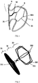
- Figure 1 illustrates a schematic diagram of a left atrial appendage occluder implanted into a left atrial appendage according to an embodiment of the present disclosure.
- the left atrial appendage 2 is located inside a left atrium 1 and between a mitral valve (not shown in figures) and a left superior pulmonary vein 4.
- the left atrial appendage occluder includes a sealing plate 31, a fixing frame 33 located on one side of the distal end of the sealing plate 31, and a connection member 32 for connecting the sealing plate 31 with the fixing frame 33.
- the sealing plate 31 is of a filament woven structure, for example, it may be of a double-layer filament woven structure.
- the sealing plate 31 may be formed by weaving metal wires (a nickel-titanium material is preferred), and then by a heat treatment.
- the number of the metal wires is 16 to 144, and before example 36 to 72, and the diameter of each metal wire is 0.01 mm to 0.8 mm.
- the sealing plate 31 is substantially in a disk shape, and its diameter is greater than the maximum diameter of an opening portion of the left atrial appendage 2.
- the sealing plate 31 may adapt to left atrial appendages 2 with various opening shapes as long as the specification of the sealing plate 31 selected is large enough to cover the opening portion of each left atrial appendage 2.
- the sealing plate 31 is arranged at the opening portion of the left atrial appendage 2 and seals the opening portion, which can prevent a flow channel built between the left atrial appendage 2 and the left atrium 1 and can prevent blood from entering the left atrial appendage 1.
- Proximal ends of the metal wires of the sealing plate 31 are gathered and fixed by a proximal fixing member 311, and distal ends of the metal wires of the sealing plate 31 are gathered and fixed by a distal fixing member 312.
- the proximal fixing member 311 and the sealing plate 31 can be fixed in a conventional way such as welding, as well as the distal fixing member 312 and the metal wires of the sealing plate 31.
- the distal fixing member 312 is connected with the connection member 32.
- the proximal fixing member 311 has threads, and the threads may be connected with a deliverer to deliver the left atrial appendage occluder.
- the interior of the sealing plate 31 is provided with a sealing film (not shown in figures), and the size of the sealing film is basically the same as that of the sealing plate 31. To be more specific, the diameter of the sealing film is equal to that of the sealing plate 31.
- the sealing film is made of a polymer material, preferably PTFE (polytetrafluoroethylene) or PET (polyethylene terephthalate).
- the sealing film may be fixed with the metal wires, which constitute the sealing plate 31, by sewing or gluing.
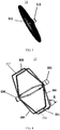
- the fixing frame 33 includes a first fixing connector 334, a second fixing connector 333 and multiple supporting rods 331.
- the first fixing connector 334 is located at the proximal end of the fixing frame 33; first ends of the multiple supporting rods 331, namely proximal ends of the supporting rods 331, are received and fixed by the first fixing connector 334; and second ends of the multiple supporting rods 331, namely distal ends of the supporting rods 331, are received and fixed by the second fixing connector 333.
- the first fixing connector 334 is connected with the connection member 32.
- the fixing frame 33 is compressed by a cavity wall 3 of the left atrial appendage 2, and then is attached to the cavity wall 3 effectively by friction force between the cavity wall 3 and the fixing frame 33. Because the two ends of the fixing frame 33 are closed, the fixing frame 33 still may provide a sufficient supporting force when it is compressed and deformed so as to ensure that the left atrial appendage occluder may be stably fixed in the left atrial appendage 1.
- the above structural features of the fixing frame allow the fixing frame to be stably fixed in the left atrial appendage 2 without anchor bars. Because of the smooth surface of the fixing frame, the fixing frame will not pierce the cavity wall 3 of the left atrial appendage 2 even if the fixing frame is arranged at a deeper position (where the cavity wall 3 is thinner) of the left atrial appendage 2.
- each supporting rod 331 includes a proximal supporting rod (also called a proximal supporting section) 336, a distal supporting rod (also called a distal supporting section) 335, and a middle supporting rod (also called a middle supporting section) 337 connected between the proximal supporting rod 336 and the distal supporting rod 335.
- the middle supporting rods 337 of the multiple supporting rods 331 are spaced to form a columnar space 330 in an encircling manner.
- Each proximal supporting rod 336 bends from one end of each middle supporting rod 337, and then connects to the first fixing connector 334 located at the axial line of the columnar space 330.
- each distal supporting rod 335 bends from another end of the middle supporting rod 337 and then connects to the second fixing connector 333 located at the axial line of the columnar space 330.
- the number of supporting rods 331 is not less than 2, and can preferably number six.
- the length of middle supporting rods is 3 mm to 30 mm, and this length may ensure that there are enough sufficient contact points and contact area between the fixing frame 33 and the cavity wall 3 of the left atrial appendage 2 to guarantee the connection is stable.
- an anchor bar 332 is arranged on the middle supporting rod 337.
- the anchor bar 332 may face to the sealing plate.
- the anchor bar 332 is used for puncturing the cavity wall 3 of the left atrial appendage 2 to assist the fixing frame 33 in fixing. It can be understood that the fixing frame 33 can firmly attached to the cavity wall 3 of the left atrial appendage 2 due to the closed structure of the fixing frame 33 at both ends, the anchor bar 332 on the fixing frame 33 may be also omitted in some embodiments to avoid piercing the cavity wall 3 of the left atrial appendage 2.
- the fixing frame 33 also may include a film 34.
- the film 34 at least covers a part, which has the anchor bars 332, of the fixing frame 33.
- the film 34 also may cover the whole outer surface of the fixing frame 33.
- the film 34 arranged on the outer surface of the fixing frame 33 may prevent a phenomenon where blood flows into the pericardium due to the fact that the anchor bars 332 pierce the cavity wall 3 of the left atrial appendage 2.
- the film 34 is also a second seal between the left atrial appendage 2 and the left atrium 1 to prevent a circulation between the left atrial appendage 2 and the left atrium 1.
- the film 34 is made of a polymer material which may be the PTFE or the PET.
- the film 34 may be attached to the fixing frame 33 by swing or gluing.
- the distal end of the second fixing connector 333 of the fixing frame 33 is spherical. And the spherical structure at the distal end of the fixing frame 33 can avoid sharp edges, so as to prevent the left atrial appendage occluder damaging the left atrial appendage 2.
- the fixing frame 33 may be formed by heat treatment after cutting a metal tube.
- the fixing frame 33 may be formed by cutting a metal (preferably a nickel-titanium material) tube with a diameter of 0.3 mm to 5 mm into a certain pattern, and then shaped by heat treatment.
- the first fixing connector 334 and the second fixing connector 333 are both integrated with the supporting rods 331.
- the spherical structure of the second fixing connector 333 may be formed by melting part of the material of the metal tube through laser or argon arc welding.
- the fixing frame 33 also may be formed by connecting multiple metal wires after these metal wires had been heat treated.
- the fixing frame 33 may be formed by connecting multiple metal wires with diameters of 0.05 mm to 0.8 mm or flat metal wires with sectional areas of (0.03 mm to 0.5 mm) x (0.5 mm to 0.03 mm) after these metal wires had been heat treated, and the metal is preferably nickel-titanium.
- the distal ends and the proximal ends of the metal wires may be fixed by welding to form the first fixing connector 334 and the second fixing connector 333.
- the spherical structure of the second fixing connector 33 also may be formed by melting part of the material of the metal tube through laser or argon arc welding.
- an included angle A between the middle supporting rod 337 and the distal supporting rods 335 is 90 degrees to 165 degrees. This included angle enables each distal supporting rod 335 to convexly extend from the corresponding end of each middle supporting rod 337 towards the distal end.
- the multiple distal supporting rods 335 form a conical surface which protrudes towards the distal end and has a vertex located outside the columnar space 330. This design of the included angle may enable the distal supporting rods 335 to resist more dramatic deformation of the middle supporting rods 337 so as to guarantee the sufficient supporting force.
- the same included angle A is also formed between the middle supporting rod 337 and the proximal supporting rod 336.
- a fixing frame 43 is of a structure similar to that of the fixing frame 33 as shown in Figure 4 , but their shapes are slightly different.
- this fixing frame 43 also has a first fixing connector 434, a second fixing connector 433 and multiple supporting rods 431 connected between the first fixing connector 434 and a second fixing connector 433.
- Each supporting rod 431 also includes a proximal supporting rod 436, a distal supporting rod 435 and a middle supporting rod 437 connected between the proximal supporting rod 436 and the distal supporting rod 435.
- Anchor bars 432 are arranged on the middle supporting rods 437.
- the distal end of the second fixing connector 433 is of a spherical structure.
- an included angle B between the middle supporting rod 437 and the distal supporting rod 435 is between 15 degrees and 90 degrees, so that all the distal supporting rods 435 form a conical surface sunken towards the proximal end in an encircling manner.
- the length of the fixing frame 43 will be greatly reduced after the left atrial appendage occluder has been implanted into the left atrial appendage 2, so that the left atrial appendage occluder may adapt to a left atrial appendage 2 with a shallow cavity and be suitable for more types of left atrial appendages 2.
- An included angle B formed between the proximal supporting rod 436 and the middle supporting rods 437, has the same size with included angle A.
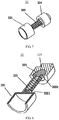
- connection member 32 includes a proximal connecting end 321, a distal connecting end 324 and a connecting rod 322 connected between the proximal connecting end 321 and the distal connecting end 324.
- the proximal connecting end 321 is connected with the sealing plate 31.
- the proximal connecting end 321 is connected with the distal fixing member 312 of the sealing plate 31.
- the connection may be realized by welding, adhering, or of interference fit or other ways.
- the distal connecting end 324 is connected with the fixing frame 33.
- the distal connecting end 324 is connected with the first fixing connector 334 of the fixing frame 33.
- the connection may be realized by welding, adhering, or of interference fit or other ways.
- the distal connecting end 324 includes a ball head structure 323 and a ball socket structure 325 which are matched with each other.
- a hinge mechanism formed by the ball head structure 323 and the ball socket structure 325, may adjust an angle within 360 degrees.
- the ball head structure 323 is connected with the connecting rod 322, and the ball socket structure 325 is connected with the fixing frame 33, so that an angle between the fixing frame 33 and the connection member 32 also may be flexibly adjusted, and the left atrial appendage occluder may adapt to left atrial appendages 2 with different shapes in a wider range.
- the proximal connecting end 321 is connected with the proximal end 3221 of the connecting rod 322 by welding, adhering, or of interference fit or other ways.
- the ball head structure 323 includes a convex spherical surface 3231 facing to the ball socket structure 325, and a convex pillar 3232 facing to the connecting rod 322.
- the ball socket structure 325 includes a convex end 3251 facing to the fixing frame 33 and a concave spherical surface 3252 facing to the ball head structure 323.
- the distal end 3222 of the connecting rod 322 is connected with the convex pillar 3232 of the ball head structure 323 by welding, adhering, or of interference fit, or other ways.
- the convex end 3251 of the ball socket structure 325 is connected with the first fixing connector 334 of the fixing frame 33.
- the convex spherical surface 3231 is contained in the concave spherical surface 3252 to form a movable connection, so that the ball socket structure 325 and the ball head structure 323 may rotate at any angle.
- connection member 32 may be made of a metal with better biocompatibility, such as stainless steel or a nickel-titanium material.
- the connecting rod 322 may be of a rod structure with a diameter of 0.1 mm to 5 mm, and also may be a spring structure. Therefore, it can not only change a connection angle between the connection member 32 and the fixing frame 33, but also adjust the length of the connection member 32, so that the left atrial appendage occluder may adapt to more left atrial appendages with different shapes, and its own movements of the left atrial appendage after the left atrial appendage occluder has been implanted into the left atrial appendage.
- the fixing frame 33 needs to find a proper fixing position in the left atrial appendage 2, but there is a relatively large included angle between this fixing position and the opening portion of the left atrial appendage 2, that is, after the left atrial appendage occluder is implanted into the left atrial appendage 2, a relatively large included angle and long distance are formed between the fixing frame 33 and the sealing plate 31.
- connection member 32 By adjusting the length and the angle of the connection member 32, it is able to adjust the included angle and the relative distance which are formed between the fixing frame 33 and the sealing plate 31, so that the fixing frame 33 of the left atrial appendage occluder can be stably fixed at a proper position in the left atrial appendage 2, and the sealing plate 31 may be optimally fitted to the opening portion of the left atrial appendage 2 to achieve sealing.
- the deformability of the sealing plate 31 is greater than that of the fixing frame 33.
- the deformability of a certain component or structure is the magnitude of a deformation of this component or structure under the action of an external force.
- the deformability described herein may be expressed by a radial length (for example the diameter) variation of the component or structure under the action of a radial force.
- the radial deformability of the sealing plate 31 of the left atrial appendage occluder is greater than that of the fixing frame 33, and/or the axial deformability of the sealing plate 31 is greater than that of the fixing frame 33.
- the radial length variation of the sealing plate 31 is greater than that of the fixing frame 33; or under the action of the same radial force, a radial length change rate of the sealing plate 31 is greater than that of the fixing frame 33; or under the action of the same axial force, a displacement of the sealing plate 31 along an axial force direction is greater than that of the fixing frame.
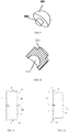
- Radial length changes of the fixing frame and the sealing plate under the action of the same radial force may be respectively tested by adopting a flat plate method.
- the left atrial appendage occluder may be tested by the flat plate method.
- radial acting forces F are applied to the fixing frame 33 by two parallel flat plates 61 and 62.
- the parallel flat plates 61 and 62 are respectively placed on two opposite sides of a diameter of the fixing frame 33, and two radial acting forces F with the same sizes and opposite directions are respectively applied to the flat plates 61 and 62 along the diameter.
- the diameter of the fixing frame 33 penetrates through and is perpendicular to a central axial line 140.
- the two parallel flat plates 61 and 62 maintain a mutually parallel state in the whole test process, namely the flat plates are parallel to the central axial line 140 all the time in the test process.
- any one of the flat plates at least covers a contour with maximum radius (for example, the middle supporting rods/sections) of the fixing frame 33, and preferably the flat plate covers the whole fixing frame 33 in a direction parallel to the central axial line 140.
- the radial lengths of portions, where the flat plates are loaded, of the fixing frame 33 are R1
- the radial length variation of the fixing frame 33, under the action of the radial forces F is a radial length difference obtained before and after radial compression, and may be expressed by AR1, so that the radial length change rate is ⁇ R1/R1.
- a thickness of the flat plates is at least 5 mm.
- the sealing plate 31 is tested by the flat plate method as above, namely the same radial acting forces F which refer to the same size, direction and acting time, are adopted.
- the radial length variation ⁇ R2 or the radial length change rate ⁇ R2/R2 of the sealing plate 31 is tested; and, at the moment, a contour with maximum radius of the sealing plate 31 is located at the edges of the double plates.
- the radial length variation ⁇ R2 of the sealing plate 31 of the left atrial appendage occluder according to the embodiment of the present disclosure is greater than the radial length variation ⁇ R1 of the fixing frame 33; or the radial length change rate ⁇ R2/R2 of the sealing plate 31 of the left atrial appendage occluder according to the embodiment of the present disclosure is greater than the radial length change rate ⁇ R1/R1 of the fixing frame 33.
- a situation that the implantation location may be improperly selected may occur.
- the fixing frame extends too deep into the cavity of the left atrial appendage, an axial length of the occluder in the naturally unfolded state would be shorter than a relative distance between the fixing frame and the sealing plate after implantation, which will lead to a mutual traction between the fixing frame and the sealing plate.
- the implanted occluder would move together with the heart, and the implanted occluder and the heart have different amplitudes or directions of motion, which may lead to the mutual traction between the fixing frame and the sealing plate.
- the fixing plate and the sealing plate pull each other through the connection member.
- the fixing frame When the fixing frame is pulled by the sealing plate, as the fixing frame is fixed in the cavity of the left atrial appendage through a radial supporting force surrounding a circumferential region of the central axial line 140, the fixing frame is attached to the circumferential region of the cavity of the left atrial appendage to resist this pulling acting force. Therefore, the fixing frame will be radially deformed under the axial acting force, and the fixing frame will separate from the cavity wall of the left atrial appendage if the acting force is large enough, and then the left atrial appendage occluder would fall off, which will cause an implantation failure.
- the sealing plate When the sealing plate is pulled by the fixing frame, the sealing plate has a disk surface structure and is connected with the connection member through the disk surface, so that the axial pulling on the sealing plate would also lead to a radial deformation of the sealing plate.
- the fixing frame and the sealing plate pull each other, the one who is easily deformed in the radial direction will be pulled by the other one.
- the fixing frame would dominate the traction and pull the sealing plate to make the sealing plate deform towards the fixing frame direction (or towards the distal end).
- Such deformation enables the sealing plate to be more close to a left atrial wall at an opening of the left atrial appendage than that of the sealing plate in the naturally unfolded state, which enhances a sealing effect between the sealing plate and the opening of the left atrial appendage and avoids an interval between the sealing plate and the left atrial wall, so that it can prevent apoplexy or systematic embolism caused by blood flowing into the cavity of the left atrial appendage and a thrombus flowing into a left atrium through the interval.
- the fixing frame dominates the traction so that the fixing frame will not easily separate from the cavity wall of the left atrial appendage under the pull of the sealing plate, and the occluder will be better fixed in the left atrial appendage to avoid falling off from the left atrial appendage.
- the above flat plate method is only an example method, and not a limitation of the present disclosure.
- An ordinary person skilled in the art can adopt any other proper method, equivalent to the flat plate method, for testing.
- a test method that the radial acting force is evenly applied to a tested component in a circumferential direction.
- three arc-shaped plates 63 may be uniformly disposed, in the same circumferential direction, on the contour with maximum radius of the tested component (the fixing frame or the sealing plate).
- radial acting forces F are simultaneously applied to the above arc-shaped plates 63 along a radial direction to test a variation or a change rate of a radial length R of the tested component.
- a thickness of the arc-shaped plates is at least 5 mm.
- the left atrial appendage occluder may be tested by a radial supporting force tester RX550-100 of the Machine Solution Inc. (MSI) Company.
- the axial deformability of the tested component is expressed by testing an axial displacement (along the direction of the central axial line 140) of the tested component under an action of the same axial force.
- the above restriction is an equidimensional restriction, that is to say, in the restriction process, the tested component does not elastically deform or just deforms a little, which may be ignored basically.
- the axial acting force is applied to a position where no elastic deformation occurs, of the tested component.
- the same axial acting forces are applied to end portions, which are connected with the connection member, of the tested component, and the axial displacement of the tested component is used to express its own deformability
- the axial displacement of the component here refers to a position of the tested component where the axial acting force is applied, and the left atrial appendage meets the condition that the axial displacement of the fixing frame is less than that of the sealing plate.
- the fixing frame and the sealing plate are independently tested, for example, only a single fixing frame or a single sealing plate is tested at each time.
- a clamping portion where the fixing frame 33 is clamped by an annular clamping member 71 along a circumferential direction, is the contour with maximum radius of the fixing frame 33.
- the annular clamping member 71 surrounds and is perpendicular to the central axial line 140.
- the radial size of the clamping portion of the fixing frame 33 is basically equal to that of a fixing frame 33 in the naturally unfolded state, so that the elastic deformation may be ignored.
- the axial displacement ⁇ O1 is used to express the deformation (or the deformability) of the fixing frame 33, and the state of the clamping member 71 itself maintains unchanged during the action of the axial acting force F1.
- the tested axial displacement represents the axial deformability of the fixing frame, which is under the pull of the sealing plate and the restricting action of the cavity of the left atrial appendage.
- the larger the axial displacement ⁇ O1 is, the easier it is for the fixing frame to be pulled and deformed.
- the tested axial displacement under the action of the axial acting force F1 represents the axial deformability of the sealing plate 31, which is under the pull of the fixing frame 33 and the restricting action of a tissue wall of the opening portion of the left atrial appendage.
- the axial displacement ⁇ O1 of the fixing frame is less than the axial displacement ⁇ O2 of the sealing plate. It can be understood that when the fixing frame and the sealing plate pull each other, the one who has a larger axial displacement will be pulled by the other one.
- the fixing frame would dominate the traction and pull the sealing plate during the traction to make the sealing plate deform towards a direction of the fixing frame (or towards the distal end).
- Such deformation enables the sealing plate to be more close to the left atrial wall at the opening of the left atrial appendage than that of the sealing plate in the naturally unfolded state, which enhances a sealing effect between the sealing plate and the opening of the left atrial appendage and avoids an interval between the sealing plate and the left atrial wall, so that it can prevent blood from flowing into the cavity of the left atrial appendage and a thrombus from flowing into a left atrium through the interval.
- the fixing frame dominates the traction so that the fixing frame will not easily separate from the cavity wall of the left atrial appendage under the pull of the sealing plate, and the occluder will be better fixed in the left atrial appendage to avoid falling off from the left atrial appendage.
- a second axial deformability test method may be further adopted.
- a clamping portion where the fixing frame 33 is clamped by an annular clamping member 76 along a circumferential direction, is a contour with maximum radius of the fixing frame 33.
- the annular clamping member surrounds, and is perpendicular, to the central axial line 140.
- the radial size of the clamping portion of the fixing frame 33 is smaller than that of a fixing frame 33 in the naturally unfolded state.
- the clamping portion of the fixing frame 33 is compressed in the radial direction; for example, the maximum radial length after compression is 80 percent of the maximum radial length before it is compressed.
- a radial force F0 may be applied to the annular clamping member 76 to compress the fixing frame 33 in the radial direction.
- An axial acting force F2 is applied to the end portion 330, where the fixing frame 33 is connected with the connection member, and the end portion 330 does not deform under the axial acting force F2, which is along the central axial line 140 and towards the direction of the sealing plate 31.
- a measurement of an axial displacement ⁇ O3 of a projection O3 of the end portion 330 on the central axial line 140 under the F2 can be made.
- the axial displacement ⁇ O3 is used to express the deformation (or the deformability) of the fixing frame 33.
- the tested axial displacement under the action of the axial acting force represents the deformability of the fixing frame 33, which is under the pull of the sealing plate 31 and the restricting action of the cavity of the left atrial appendage.
- the sealing plate 31 includes a distal fixing member 312; and the connection member is connected with the distal fixing member 312.
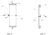
- an annular fixing member 77 abuts a disk surface, which is towards the fixing frame 33 and is located at the maximum edge of the sealing plate 31.
- the axial acting force F2 along the central axial line 140 and towards a direction of the fixing frame 33, is applied to the distal fixing member 312.
- a position where the disk surface is abutted maintains unchanged along the direction of the central axial line 140 due to the annular fixing member 77, thereby testing a projection displacement ⁇ O4 of the distal fixing member 312 on the central axial line 140.
- Such deformation enables the sealing plate to closer to the left atrial wall at the opening portion of the left atrial appendage than that of the sealing plate in the naturally unfolded state, which enhances a sealing effect between the sealing plate and the opening of the left atrial appendage and avoids an interval between the sealing plate and the left atrial wall, so that it can prevent blood from flowing into the cavity of the left atrial appendage and a thrombus from flowing into a left atrium through the interval.
- the fixing frame dominates the traction so that the fixing frame will not easily separate from the cavity wall of the left atrial appendage under the pull of the sealing plate, and the occluder will be better fixed in the left atrial appendage to avoid falling off from the left atrial appendage.
- the left atrial appendage occluder provided by the present disclosure has the following beneficial effects:
Landscapes
- Health & Medical Sciences (AREA)
- Life Sciences & Earth Sciences (AREA)
- Surgery (AREA)
- Animal Behavior & Ethology (AREA)
- Veterinary Medicine (AREA)
- Public Health (AREA)
- Engineering & Computer Science (AREA)
- Biomedical Technology (AREA)
- Heart & Thoracic Surgery (AREA)
- General Health & Medical Sciences (AREA)
- Vascular Medicine (AREA)
- Molecular Biology (AREA)
- Medical Informatics (AREA)
- Nuclear Medicine, Radiotherapy & Molecular Imaging (AREA)
- Reproductive Health (AREA)
- Cardiology (AREA)
- Gastroenterology & Hepatology (AREA)
- Pulmonology (AREA)
- Oral & Maxillofacial Surgery (AREA)
- Transplantation (AREA)
- Surgical Instruments (AREA)
- Prostheses (AREA)
Applications Claiming Priority (2)
| Application Number | Priority Date | Filing Date | Title |
|---|---|---|---|
| CN201511033727.0A CN106923886B (zh) | 2015-12-31 | 2015-12-31 | 左心耳封堵器 |
| PCT/CN2016/086113 WO2017113631A1 (zh) | 2015-12-31 | 2016-06-17 | 左心耳封堵器 |
Publications (3)
| Publication Number | Publication Date |
|---|---|
| EP3398535A1 true EP3398535A1 (de) | 2018-11-07 |
| EP3398535A4 EP3398535A4 (de) | 2019-08-21 |
| EP3398535B1 EP3398535B1 (de) | 2021-12-01 |
Family
ID=59224311
Family Applications (1)
| Application Number | Title | Priority Date | Filing Date |
|---|---|---|---|
| EP16880439.1A Active EP3398535B1 (de) | 2015-12-31 | 2016-06-17 | Verschluss für linkes herzohr |
Country Status (4)
| Country | Link |
|---|---|
| US (1) | US11253241B2 (de) |
| EP (1) | EP3398535B1 (de) |
| CN (1) | CN106923886B (de) |
| WO (1) | WO2017113631A1 (de) |
Families Citing this family (20)
| Publication number | Priority date | Publication date | Assignee | Title |
|---|---|---|---|---|
| EP2968878B1 (de) | 2013-03-13 | 2020-08-12 | Conformal Medical, Inc. | Vorrichtungen zum ausschluss des linken vorhofanhangs |
| US11399842B2 (en) | 2013-03-13 | 2022-08-02 | Conformal Medical, Inc. | Devices and methods for excluding the left atrial appendage |
| AU2015249283B2 (en) | 2014-04-25 | 2019-07-18 | Flow Medtech, Llc | Left atrial appendage occlusion device |
| WO2016044740A1 (en) | 2014-09-19 | 2016-03-24 | Flow Medtech, Inc. | Left atrial appendage occlusion device delivery system |
| US11426172B2 (en) | 2016-10-27 | 2022-08-30 | Conformal Medical, Inc. | Devices and methods for excluding the left atrial appendage |
| EP4516244A3 (de) | 2016-10-27 | 2025-09-03 | Conformal Medical, Inc. | Vorrichtungen zum ausschluss des linken herzohrs |
| JP2020536692A (ja) * | 2017-10-17 | 2020-12-17 | シャンハイ マイクロポート メディカル (グループ) カンパニー リミテッド | 左心耳閉鎖デバイス及び左心耳閉鎖システム |
| WO2020123386A1 (en) * | 2018-12-10 | 2020-06-18 | Boston Scientific Scimed, Inc. | Left atrial appendage implant with sealing balloon |
| CN109464173B (zh) * | 2018-12-20 | 2024-04-02 | 先健科技(深圳)有限公司 | 封堵装置 |
| CN113710171B (zh) | 2019-02-08 | 2024-08-16 | 保形医疗公司 | 用于除去左心耳的装置和方法 |
| US12144508B2 (en) | 2019-02-08 | 2024-11-19 | Conformal Medical, Inc. | Devices and methods for excluding the left atrial appendage |
| CN109700496B (zh) * | 2019-03-06 | 2025-04-25 | 中南大学湘雅医院 | 一种心脏封堵器 |
| WO2020198259A1 (en) * | 2019-03-25 | 2020-10-01 | Laminar, Inc. | Devices and systems for treating the left atrial appendage |
| CN111643145B (zh) * | 2020-06-28 | 2021-07-20 | 哈尔滨工业大学 | 一种左心耳封堵器及其制备方法 |
| US11771410B2 (en) * | 2020-08-03 | 2023-10-03 | St. Jude Medical, Cardiology Division, Inc. | Devices and methods for the treatment of vascular abnormalities |
| US20220401109A1 (en) * | 2021-06-22 | 2022-12-22 | Ventrimend, Inc | Systems and methods for treating the left atrial appendage |
| CN113679514B (zh) * | 2021-08-26 | 2024-08-02 | 胡桂仙 | 一种缺损骨窗自闭式锚定装置以及鞍底缺损重建方法 |
| CN114246631A (zh) * | 2022-02-28 | 2022-03-29 | 上海介入医疗器械有限公司 | 封堵器及封堵组件 |
| CN117338353A (zh) * | 2023-10-27 | 2024-01-05 | 上海锦葵医疗器械股份有限公司 | 组合式的封堵装置 |
| CN119908772A (zh) * | 2024-12-26 | 2025-05-02 | 深圳市先健呼吸科技有限公司 | 气管/食管装置及系统 |
Family Cites Families (47)
| Publication number | Priority date | Publication date | Assignee | Title |
|---|---|---|---|---|
| US3874388A (en) * | 1973-02-12 | 1975-04-01 | Ochsner Med Found Alton | Shunt defect closure system |
| US5944738A (en) * | 1998-02-06 | 1999-08-31 | Aga Medical Corporation | Percutaneous catheter directed constricting occlusion device |
| US7044134B2 (en) * | 1999-11-08 | 2006-05-16 | Ev3 Sunnyvale, Inc | Method of implanting a device in the left atrial appendage |
| US7128073B1 (en) * | 1998-11-06 | 2006-10-31 | Ev3 Endovascular, Inc. | Method and device for left atrial appendage occlusion |
| US7288105B2 (en) * | 2001-08-01 | 2007-10-30 | Ev3 Endovascular, Inc. | Tissue opening occluder |
| US20040093017A1 (en) * | 2002-11-06 | 2004-05-13 | Nmt Medical, Inc. | Medical devices utilizing modified shape memory alloy |
| DE602004018282D1 (de) * | 2003-03-17 | 2009-01-22 | Ev3 Endovascular Inc | Stent mit laminierter dünnfilmverbund |
| EP2481356B1 (de) * | 2003-07-14 | 2013-09-11 | W.L. Gore & Associates, Inc. | Rohrförmige Verschlussvorrichtung mit Sperrsystem für persistierendes Foramen ovale (PFO) |
| EP3345577A1 (de) * | 2003-12-04 | 2018-07-11 | Boston Scientific Scimed, Inc. | System zur ausgabe der rückhaltevorrichtung eines linken vorhofohrs |
| US8777974B2 (en) * | 2004-03-19 | 2014-07-15 | Aga Medical Corporation | Multi-layer braided structures for occluding vascular defects |
| CN100413471C (zh) * | 2004-06-25 | 2008-08-27 | 深圳市先健科技股份有限公司 | 输送左心耳闭塞装置的输送器 |
| US8366743B2 (en) * | 2005-01-28 | 2013-02-05 | Lifetech Scientific (Shenzhen) Co., Ltd | Heart septal defect occlusion device |
| WO2006130836A2 (en) * | 2005-06-02 | 2006-12-07 | Cordis Corporation | Patent foramen ovale closure device |
| US7972359B2 (en) * | 2005-09-16 | 2011-07-05 | Atritech, Inc. | Intracardiac cage and method of delivering same |
| JP2009532123A (ja) * | 2006-03-31 | 2009-09-10 | エヌエムティー メディカル, インコーポレイティッド | 可変長の卵円孔開存(pfo)オクルーダ及びキャッチシステム |
| US7938826B2 (en) * | 2006-05-30 | 2011-05-10 | Coherex Medical, Inc. | Methods, systems, and devices for closing a patent foramen ovale using mechanical structures |
| US8784469B2 (en) * | 2011-06-30 | 2014-07-22 | Ghassan S. Kassab | Devices, systems, and methods for inverting and closing the left atrial appendage |
| ES2856081T3 (es) * | 2007-04-16 | 2021-09-27 | Occlutech Holding Ag | Oclusor para la oclusión de una orejuela auricular y procedimiento de producción del mismo |
| US8034061B2 (en) * | 2007-07-12 | 2011-10-11 | Aga Medical Corporation | Percutaneous catheter directed intravascular occlusion devices |
| US9414842B2 (en) * | 2007-10-12 | 2016-08-16 | St. Jude Medical, Cardiology Division, Inc. | Multi-component vascular device |
| WO2009052432A2 (en) * | 2007-10-19 | 2009-04-23 | Coherex Medical, Inc. | Medical device for modification of left atrial appendange and related systems and methods |
| US20090171386A1 (en) * | 2007-12-28 | 2009-07-02 | Aga Medical Corporation | Percutaneous catheter directed intravascular occlusion devices |
| US10702275B2 (en) * | 2009-02-18 | 2020-07-07 | St. Jude Medical Cardiology Division, Inc. | Medical device with stiffener wire for occluding vascular defects |
| US20110054515A1 (en) * | 2009-08-25 | 2011-03-03 | John Bridgeman | Device and method for occluding the left atrial appendage |
| EP2387950A1 (de) * | 2010-05-23 | 2011-11-23 | Occlutech Holding AG | Medizinisches Implantat und Herstellungsverfahren dafür |
| CN103249374B (zh) * | 2010-07-02 | 2015-08-05 | Pfm医疗股份公司 | 左心耳封堵装置 |
| CN101933850B (zh) * | 2010-09-16 | 2012-07-18 | 先健科技(深圳)有限公司 | 封堵器及其制造方法 |
| US9186152B2 (en) * | 2010-11-12 | 2015-11-17 | W. L. Gore & Associates, Inc. | Left atrial appendage occlusive devices |
| EP2672927A4 (de) * | 2011-02-10 | 2014-08-20 | Atrial Innovations Inc | Behandlung von herzohr-okklusionen und -arrhythmien |
| EP2524653A1 (de) * | 2011-05-17 | 2012-11-21 | Carag AG | Verschlusselement |
| CN102805654B (zh) * | 2011-06-01 | 2014-04-02 | 先健科技(深圳)有限公司 | 左心耳封堵器 |
| US8764787B2 (en) * | 2011-06-17 | 2014-07-01 | Aga Medical Corporation | Occlusion device and associated deployment method |
| US10307167B2 (en) * | 2012-12-14 | 2019-06-04 | Corquest Medical, Inc. | Assembly and method for left atrial appendage occlusion |
| US8758389B2 (en) * | 2011-11-18 | 2014-06-24 | Aga Medical Corporation | Devices and methods for occluding abnormal openings in a patient's vasculature |
| US9592058B2 (en) * | 2012-02-21 | 2017-03-14 | Cardia, Inc. | Left atrial appendage occlusion device |
| US10531878B2 (en) * | 2012-07-26 | 2020-01-14 | University Of Louisville Research Foundation | Atrial appendage closure device and related methods |
| US20140135817A1 (en) * | 2012-11-14 | 2014-05-15 | Boston Scientific Scimed, Inc. | Left atrial appendage closure implant |
| US9763666B2 (en) * | 2013-02-19 | 2017-09-19 | Apt Medical Inc. | Left atrial appendage plugging device and delivery system |
| US11911258B2 (en) * | 2013-06-26 | 2024-02-27 | W. L. Gore & Associates, Inc. | Space filling devices |
| JP6431906B2 (ja) * | 2013-10-10 | 2018-11-28 | カラク アーゲー | オクルーダー |
| CN103598902B (zh) * | 2013-11-14 | 2017-01-25 | 先健科技(深圳)有限公司 | 左心耳封堵器 |
| DE102013019890A1 (de) * | 2013-11-28 | 2015-05-28 | Bentley Innomed Gmbh | Medizinisches Implantat |
| CN104352260B (zh) * | 2014-10-13 | 2017-11-21 | 深圳市科奕顿生物医疗科技有限公司 | 左心耳封堵系统 |
| CN104398284A (zh) * | 2014-11-24 | 2015-03-11 | 上海普实医疗器械科技有限公司 | 一种新型左心耳封堵器及制造方法 |
| EP3028652A1 (de) * | 2014-12-03 | 2016-06-08 | Peter Osypka Stiftung | Verschlussvorrichtung geeignet zum Verschließen des linken Herz Ohrs |
| CN104856741B (zh) * | 2015-06-15 | 2017-11-10 | 同济大学附属第十人民医院 | 一种经导管左心耳封堵系统 |
| US20170035433A1 (en) * | 2015-08-06 | 2017-02-09 | Thomas J. Forbes | Left atrial appendage occluder device anchoring system, anchor, and method of attachment |
-
2015
- 2015-12-31 CN CN201511033727.0A patent/CN106923886B/zh active Active
-
2016
- 2016-06-17 WO PCT/CN2016/086113 patent/WO2017113631A1/zh not_active Ceased
- 2016-06-17 EP EP16880439.1A patent/EP3398535B1/de active Active
- 2016-06-17 US US16/066,832 patent/US11253241B2/en active Active
Also Published As
| Publication number | Publication date |
|---|---|
| WO2017113631A1 (zh) | 2017-07-06 |
| US20190008495A1 (en) | 2019-01-10 |
| EP3398535B1 (de) | 2021-12-01 |
| CN106923886B (zh) | 2022-04-22 |
| CN106923886A (zh) | 2017-07-07 |
| US11253241B2 (en) | 2022-02-22 |
| EP3398535A4 (de) | 2019-08-21 |
Similar Documents
| Publication | Publication Date | Title |
|---|---|---|
| US11253241B2 (en) | Left atrial appendage occluder | |
| EP3398536B1 (de) | Verschluss für linkes herzohr | |
| EP2757957B1 (de) | Medizinische, implantierbare okklusionsvorrichtung | |
| EP2263553B1 (de) | Über einen perkutanen Katheter gesteuerte Vorrichtungen für intravaskuläre Verstopfungen | |
| EP4241695B1 (de) | Okklusionsvorrichtung für linkes herzohr | |
| EP3072461B1 (de) | Verschluss für linkes herzohr | |
| US10624648B2 (en) | Left atrial appendage Occluder | |
| CN102805654B (zh) | 左心耳封堵器 | |
| CN106923885B (zh) | 左心耳封堵器 | |
| US20170095256A1 (en) | Left Atrial Appendage Occluder | |
| US10765416B2 (en) | Left atrial appendage occluder | |
| US20240074762A1 (en) | Left Atrial Appendage Occluder | |
| EP3369388B1 (de) | Verschluss für linkes herzohr | |
| WO2007149337A2 (en) | Occlusion device with flexible fabric connector | |
| WO2007149336A2 (en) | Occlusion device with flexible polymeric connector | |
| CN215349158U (zh) | 用于封堵心房间隔的介入设备 |
Legal Events
| Date | Code | Title | Description |
|---|---|---|---|
| STAA | Information on the status of an ep patent application or granted ep patent |
Free format text: STATUS: THE INTERNATIONAL PUBLICATION HAS BEEN MADE |
|
| PUAI | Public reference made under article 153(3) epc to a published international application that has entered the european phase |
Free format text: ORIGINAL CODE: 0009012 |
|
| STAA | Information on the status of an ep patent application or granted ep patent |
Free format text: STATUS: REQUEST FOR EXAMINATION WAS MADE |
|
| 17P | Request for examination filed |
Effective date: 20180731 |
|
| AK | Designated contracting states |
Kind code of ref document: A1 Designated state(s): AL AT BE BG CH CY CZ DE DK EE ES FI FR GB GR HR HU IE IS IT LI LT LU LV MC MK MT NL NO PL PT RO RS SE SI SK SM TR |
|
| AX | Request for extension of the european patent |
Extension state: BA ME |
|
| DAV | Request for validation of the european patent (deleted) | ||
| DAX | Request for extension of the european patent (deleted) | ||
| A4 | Supplementary search report drawn up and despatched |
Effective date: 20190722 |
|
| RIC1 | Information provided on ipc code assigned before grant |
Ipc: A61B 17/12 20060101AFI20190716BHEP |
|
| GRAP | Despatch of communication of intention to grant a patent |
Free format text: ORIGINAL CODE: EPIDOSNIGR1 |
|
| STAA | Information on the status of an ep patent application or granted ep patent |
Free format text: STATUS: GRANT OF PATENT IS INTENDED |
|
| RIC1 | Information provided on ipc code assigned before grant |
Ipc: A61B 17/12 20060101AFI20210531BHEP |
|
| INTG | Intention to grant announced |
Effective date: 20210618 |
|
| GRAS | Grant fee paid |
Free format text: ORIGINAL CODE: EPIDOSNIGR3 |
|
| GRAA | (expected) grant |
Free format text: ORIGINAL CODE: 0009210 |
|
| STAA | Information on the status of an ep patent application or granted ep patent |
Free format text: STATUS: THE PATENT HAS BEEN GRANTED |
|
| RAP3 | Party data changed (applicant data changed or rights of an application transferred) |
Owner name: LIFETECH SCIENTIFIC (SHENZHEN) CO., LTD. |
|
| AK | Designated contracting states |
Kind code of ref document: B1 Designated state(s): AL AT BE BG CH CY CZ DE DK EE ES FI FR GB GR HR HU IE IS IT LI LT LU LV MC MK MT NL NO PL PT RO RS SE SI SK SM TR |
|
| REG | Reference to a national code |
Ref country code: GB Ref legal event code: FG4D |
|
| REG | Reference to a national code |
Ref country code: AT Ref legal event code: REF Ref document number: 1451030 Country of ref document: AT Kind code of ref document: T Effective date: 20211215 Ref country code: CH Ref legal event code: EP |
|
| REG | Reference to a national code |
Ref country code: IE Ref legal event code: FG4D |
|
| REG | Reference to a national code |
Ref country code: DE Ref legal event code: R096 Ref document number: 602016066991 Country of ref document: DE |
|
| REG | Reference to a national code |
Ref country code: LT Ref legal event code: MG9D |
|
| REG | Reference to a national code |
Ref country code: NL Ref legal event code: MP Effective date: 20211201 |
|
| REG | Reference to a national code |
Ref country code: AT Ref legal event code: MK05 Ref document number: 1451030 Country of ref document: AT Kind code of ref document: T Effective date: 20211201 |
|
| PG25 | Lapsed in a contracting state [announced via postgrant information from national office to epo] |
Ref country code: RS Free format text: LAPSE BECAUSE OF FAILURE TO SUBMIT A TRANSLATION OF THE DESCRIPTION OR TO PAY THE FEE WITHIN THE PRESCRIBED TIME-LIMIT Effective date: 20211201 Ref country code: LT Free format text: LAPSE BECAUSE OF FAILURE TO SUBMIT A TRANSLATION OF THE DESCRIPTION OR TO PAY THE FEE WITHIN THE PRESCRIBED TIME-LIMIT Effective date: 20211201 Ref country code: FI Free format text: LAPSE BECAUSE OF FAILURE TO SUBMIT A TRANSLATION OF THE DESCRIPTION OR TO PAY THE FEE WITHIN THE PRESCRIBED TIME-LIMIT Effective date: 20211201 Ref country code: BG Free format text: LAPSE BECAUSE OF FAILURE TO SUBMIT A TRANSLATION OF THE DESCRIPTION OR TO PAY THE FEE WITHIN THE PRESCRIBED TIME-LIMIT Effective date: 20220301 Ref country code: AT Free format text: LAPSE BECAUSE OF FAILURE TO SUBMIT A TRANSLATION OF THE DESCRIPTION OR TO PAY THE FEE WITHIN THE PRESCRIBED TIME-LIMIT Effective date: 20211201 |
|
| PG25 | Lapsed in a contracting state [announced via postgrant information from national office to epo] |
Ref country code: SE Free format text: LAPSE BECAUSE OF FAILURE TO SUBMIT A TRANSLATION OF THE DESCRIPTION OR TO PAY THE FEE WITHIN THE PRESCRIBED TIME-LIMIT Effective date: 20211201 Ref country code: PL Free format text: LAPSE BECAUSE OF FAILURE TO SUBMIT A TRANSLATION OF THE DESCRIPTION OR TO PAY THE FEE WITHIN THE PRESCRIBED TIME-LIMIT Effective date: 20211201 Ref country code: NO Free format text: LAPSE BECAUSE OF FAILURE TO SUBMIT A TRANSLATION OF THE DESCRIPTION OR TO PAY THE FEE WITHIN THE PRESCRIBED TIME-LIMIT Effective date: 20220301 Ref country code: LV Free format text: LAPSE BECAUSE OF FAILURE TO SUBMIT A TRANSLATION OF THE DESCRIPTION OR TO PAY THE FEE WITHIN THE PRESCRIBED TIME-LIMIT Effective date: 20211201 Ref country code: HR Free format text: LAPSE BECAUSE OF FAILURE TO SUBMIT A TRANSLATION OF THE DESCRIPTION OR TO PAY THE FEE WITHIN THE PRESCRIBED TIME-LIMIT Effective date: 20211201 Ref country code: GR Free format text: LAPSE BECAUSE OF FAILURE TO SUBMIT A TRANSLATION OF THE DESCRIPTION OR TO PAY THE FEE WITHIN THE PRESCRIBED TIME-LIMIT Effective date: 20220302 Ref country code: ES Free format text: LAPSE BECAUSE OF FAILURE TO SUBMIT A TRANSLATION OF THE DESCRIPTION OR TO PAY THE FEE WITHIN THE PRESCRIBED TIME-LIMIT Effective date: 20211201 |
|
| PG25 | Lapsed in a contracting state [announced via postgrant information from national office to epo] |
Ref country code: NL Free format text: LAPSE BECAUSE OF FAILURE TO SUBMIT A TRANSLATION OF THE DESCRIPTION OR TO PAY THE FEE WITHIN THE PRESCRIBED TIME-LIMIT Effective date: 20211201 |
|
| PG25 | Lapsed in a contracting state [announced via postgrant information from national office to epo] |
Ref country code: SM Free format text: LAPSE BECAUSE OF FAILURE TO SUBMIT A TRANSLATION OF THE DESCRIPTION OR TO PAY THE FEE WITHIN THE PRESCRIBED TIME-LIMIT Effective date: 20211201 Ref country code: SK Free format text: LAPSE BECAUSE OF FAILURE TO SUBMIT A TRANSLATION OF THE DESCRIPTION OR TO PAY THE FEE WITHIN THE PRESCRIBED TIME-LIMIT Effective date: 20211201 Ref country code: RO Free format text: LAPSE BECAUSE OF FAILURE TO SUBMIT A TRANSLATION OF THE DESCRIPTION OR TO PAY THE FEE WITHIN THE PRESCRIBED TIME-LIMIT Effective date: 20211201 Ref country code: PT Free format text: LAPSE BECAUSE OF FAILURE TO SUBMIT A TRANSLATION OF THE DESCRIPTION OR TO PAY THE FEE WITHIN THE PRESCRIBED TIME-LIMIT Effective date: 20220401 Ref country code: EE Free format text: LAPSE BECAUSE OF FAILURE TO SUBMIT A TRANSLATION OF THE DESCRIPTION OR TO PAY THE FEE WITHIN THE PRESCRIBED TIME-LIMIT Effective date: 20211201 Ref country code: CZ Free format text: LAPSE BECAUSE OF FAILURE TO SUBMIT A TRANSLATION OF THE DESCRIPTION OR TO PAY THE FEE WITHIN THE PRESCRIBED TIME-LIMIT Effective date: 20211201 |
|
| REG | Reference to a national code |
Ref country code: DE Ref legal event code: R097 Ref document number: 602016066991 Country of ref document: DE |
|
| PG25 | Lapsed in a contracting state [announced via postgrant information from national office to epo] |
Ref country code: IS Free format text: LAPSE BECAUSE OF FAILURE TO SUBMIT A TRANSLATION OF THE DESCRIPTION OR TO PAY THE FEE WITHIN THE PRESCRIBED TIME-LIMIT Effective date: 20220401 |
|
| PLBE | No opposition filed within time limit |
Free format text: ORIGINAL CODE: 0009261 |
|
| STAA | Information on the status of an ep patent application or granted ep patent |
Free format text: STATUS: NO OPPOSITION FILED WITHIN TIME LIMIT |
|
| PG25 | Lapsed in a contracting state [announced via postgrant information from national office to epo] |
Ref country code: DK Free format text: LAPSE BECAUSE OF FAILURE TO SUBMIT A TRANSLATION OF THE DESCRIPTION OR TO PAY THE FEE WITHIN THE PRESCRIBED TIME-LIMIT Effective date: 20211201 Ref country code: AL Free format text: LAPSE BECAUSE OF FAILURE TO SUBMIT A TRANSLATION OF THE DESCRIPTION OR TO PAY THE FEE WITHIN THE PRESCRIBED TIME-LIMIT Effective date: 20211201 |
|
| 26N | No opposition filed |
Effective date: 20220902 |
|
| PG25 | Lapsed in a contracting state [announced via postgrant information from national office to epo] |
Ref country code: SI Free format text: LAPSE BECAUSE OF FAILURE TO SUBMIT A TRANSLATION OF THE DESCRIPTION OR TO PAY THE FEE WITHIN THE PRESCRIBED TIME-LIMIT Effective date: 20211201 |
|
| PG25 | Lapsed in a contracting state [announced via postgrant information from national office to epo] |
Ref country code: MC Free format text: LAPSE BECAUSE OF FAILURE TO SUBMIT A TRANSLATION OF THE DESCRIPTION OR TO PAY THE FEE WITHIN THE PRESCRIBED TIME-LIMIT Effective date: 20211201 |
|
| REG | Reference to a national code |
Ref country code: CH Ref legal event code: PL |
|
| REG | Reference to a national code |
Ref country code: BE Ref legal event code: MM Effective date: 20220630 |
|
| GBPC | Gb: european patent ceased through non-payment of renewal fee |
Effective date: 20220617 |
|
| PG25 | Lapsed in a contracting state [announced via postgrant information from national office to epo] |
Ref country code: LU Free format text: LAPSE BECAUSE OF NON-PAYMENT OF DUE FEES Effective date: 20220617 Ref country code: LI Free format text: LAPSE BECAUSE OF NON-PAYMENT OF DUE FEES Effective date: 20220630 Ref country code: IE Free format text: LAPSE BECAUSE OF NON-PAYMENT OF DUE FEES Effective date: 20220617 Ref country code: FR Free format text: LAPSE BECAUSE OF NON-PAYMENT OF DUE FEES Effective date: 20220630 Ref country code: CH Free format text: LAPSE BECAUSE OF NON-PAYMENT OF DUE FEES Effective date: 20220630 |
|
| PG25 | Lapsed in a contracting state [announced via postgrant information from national office to epo] |
Ref country code: IT Free format text: LAPSE BECAUSE OF FAILURE TO SUBMIT A TRANSLATION OF THE DESCRIPTION OR TO PAY THE FEE WITHIN THE PRESCRIBED TIME-LIMIT Effective date: 20211201 Ref country code: GB Free format text: LAPSE BECAUSE OF NON-PAYMENT OF DUE FEES Effective date: 20220617 Ref country code: BE Free format text: LAPSE BECAUSE OF NON-PAYMENT OF DUE FEES Effective date: 20220630 |
|
| P01 | Opt-out of the competence of the unified patent court (upc) registered |
Effective date: 20230515 |
|
| PG25 | Lapsed in a contracting state [announced via postgrant information from national office to epo] |
Ref country code: HU Free format text: LAPSE BECAUSE OF FAILURE TO SUBMIT A TRANSLATION OF THE DESCRIPTION OR TO PAY THE FEE WITHIN THE PRESCRIBED TIME-LIMIT; INVALID AB INITIO Effective date: 20160617 |
|
| PG25 | Lapsed in a contracting state [announced via postgrant information from national office to epo] |
Ref country code: MK Free format text: LAPSE BECAUSE OF FAILURE TO SUBMIT A TRANSLATION OF THE DESCRIPTION OR TO PAY THE FEE WITHIN THE PRESCRIBED TIME-LIMIT Effective date: 20211201 Ref country code: CY Free format text: LAPSE BECAUSE OF FAILURE TO SUBMIT A TRANSLATION OF THE DESCRIPTION OR TO PAY THE FEE WITHIN THE PRESCRIBED TIME-LIMIT Effective date: 20211201 |
|
| PG25 | Lapsed in a contracting state [announced via postgrant information from national office to epo] |
Ref country code: MT Free format text: LAPSE BECAUSE OF FAILURE TO SUBMIT A TRANSLATION OF THE DESCRIPTION OR TO PAY THE FEE WITHIN THE PRESCRIBED TIME-LIMIT Effective date: 20211201 |
|
| PGFP | Annual fee paid to national office [announced via postgrant information from national office to epo] |
Ref country code: DE Payment date: 20250617 Year of fee payment: 10 |
|
| PG25 | Lapsed in a contracting state [announced via postgrant information from national office to epo] |
Ref country code: TR Free format text: LAPSE BECAUSE OF FAILURE TO SUBMIT A TRANSLATION OF THE DESCRIPTION OR TO PAY THE FEE WITHIN THE PRESCRIBED TIME-LIMIT Effective date: 20211201 |