EP3397542B1 - Track chain mechanism - Google Patents
Track chain mechanism Download PDFInfo
- Publication number
- EP3397542B1 EP3397542B1 EP16828954.4A EP16828954A EP3397542B1 EP 3397542 B1 EP3397542 B1 EP 3397542B1 EP 16828954 A EP16828954 A EP 16828954A EP 3397542 B1 EP3397542 B1 EP 3397542B1
- Authority
- EP
- European Patent Office
- Prior art keywords
- track
- frame
- vehicle
- suspension
- shaft
- Prior art date
- Legal status (The legal status is an assumption and is not a legal conclusion. Google has not performed a legal analysis and makes no representation as to the accuracy of the status listed.)
- Active
Links
- 230000007246 mechanism Effects 0.000 title claims description 52
- 239000000725 suspension Substances 0.000 claims description 91
- 238000006073 displacement reaction Methods 0.000 description 10
- 239000000203 mixture Substances 0.000 description 4
- 229910000906 Bronze Inorganic materials 0.000 description 3
- 238000010521 absorption reaction Methods 0.000 description 3
- 239000010974 bronze Substances 0.000 description 3
- KUNSUQLRTQLHQQ-UHFFFAOYSA-N copper tin Chemical compound [Cu].[Sn] KUNSUQLRTQLHQQ-UHFFFAOYSA-N 0.000 description 3
- 230000035939 shock Effects 0.000 description 3
- 238000004904 shortening Methods 0.000 description 3
- 230000009286 beneficial effect Effects 0.000 description 2
- 238000012423 maintenance Methods 0.000 description 2
- 230000006835 compression Effects 0.000 description 1
- 238000007906 compression Methods 0.000 description 1
- 230000008602 contraction Effects 0.000 description 1
- 230000009193 crawling Effects 0.000 description 1
Images



Classifications
-
- B—PERFORMING OPERATIONS; TRANSPORTING
- B62—LAND VEHICLES FOR TRAVELLING OTHERWISE THAN ON RAILS
- B62D—MOTOR VEHICLES; TRAILERS
- B62D55/00—Endless track vehicles
- B62D55/08—Endless track units; Parts thereof
- B62D55/104—Suspension devices for wheels, rollers, bogies or frames
- B62D55/116—Attitude or position control of chassis by action on suspension, e.g. to compensate for a slope
-
- B—PERFORMING OPERATIONS; TRANSPORTING
- B60—VEHICLES IN GENERAL
- B60G—VEHICLE SUSPENSION ARRANGEMENTS
- B60G11/00—Resilient suspensions characterised by arrangement, location or kind of springs
- B60G11/32—Resilient suspensions characterised by arrangement, location or kind of springs having springs of different kinds
- B60G11/48—Resilient suspensions characterised by arrangement, location or kind of springs having springs of different kinds not including leaf springs
- B60G11/56—Resilient suspensions characterised by arrangement, location or kind of springs having springs of different kinds not including leaf springs having helical, spiral or coil springs, and also fluid springs
- B60G11/58—Resilient suspensions characterised by arrangement, location or kind of springs having springs of different kinds not including leaf springs having helical, spiral or coil springs, and also fluid springs arranged coaxially
-
- B—PERFORMING OPERATIONS; TRANSPORTING
- B60—VEHICLES IN GENERAL
- B60G—VEHICLE SUSPENSION ARRANGEMENTS
- B60G5/00—Resilient suspensions for a set of tandem wheels or axles having interrelated movements
-
- B—PERFORMING OPERATIONS; TRANSPORTING
- B62—LAND VEHICLES FOR TRAVELLING OTHERWISE THAN ON RAILS
- B62D—MOTOR VEHICLES; TRAILERS
- B62D55/00—Endless track vehicles
- B62D55/06—Endless track vehicles with tracks without ground wheels
-
- B—PERFORMING OPERATIONS; TRANSPORTING
- B62—LAND VEHICLES FOR TRAVELLING OTHERWISE THAN ON RAILS
- B62D—MOTOR VEHICLES; TRAILERS
- B62D55/00—Endless track vehicles
- B62D55/08—Endless track units; Parts thereof
- B62D55/084—Endless-track units or carriages mounted separably, adjustably or extensibly on vehicles, e.g. portable track units
-
- B—PERFORMING OPERATIONS; TRANSPORTING
- B62—LAND VEHICLES FOR TRAVELLING OTHERWISE THAN ON RAILS
- B62D—MOTOR VEHICLES; TRAILERS
- B62D55/00—Endless track vehicles
- B62D55/08—Endless track units; Parts thereof
- B62D55/10—Bogies; Frames
-
- B—PERFORMING OPERATIONS; TRANSPORTING
- B62—LAND VEHICLES FOR TRAVELLING OTHERWISE THAN ON RAILS
- B62D—MOTOR VEHICLES; TRAILERS
- B62D55/00—Endless track vehicles
- B62D55/08—Endless track units; Parts thereof
- B62D55/104—Suspension devices for wheels, rollers, bogies or frames
-
- B—PERFORMING OPERATIONS; TRANSPORTING
- B60—VEHICLES IN GENERAL
- B60G—VEHICLE SUSPENSION ARRANGEMENTS
- B60G2300/00—Indexing codes relating to the type of vehicle
- B60G2300/32—Track vehicles
Definitions
- the present invention relates to crawler vehicles and more particular to track chain suspension mechanisms, which provide for a smooth and levelled operation of the vehicle.
- the track chain suspension mechanisms is of particular use to machines for laying concrete paths of the type in which a concrete mix in the plastic state is spread over a certain width and levelled by means of a levelling element suspended behind the machine.
- the track chain suspension mechanism of the present invention is characterized in having a first and a second track frame, the first frame being suspended to the vehicle by means of a suspension shaft pivotally and slidable mounted to a suspsension frame, the second track frame pivotally connected to the vehicle by means of a drive shaft mounted to a drive frame and wherein said first and second track frame pivotally connected to one another by means of a pivot shaft.
- the track chain suspension mechanism is further characterized in comprising only one idler at the front of the first track frame.
- the drive shaft mounted as low as possible to the ground.
- the drive shaft is mounted below the rotation axis of the Idlers when the track chain suspension mechanism is in level position.
- This invention relates to crawler vehicles and more particularly to track chain suspensions therefor.
- the track chain of most commercial crawler vehicles is usually engaged on a pair of large longitudinally spaced wheels wherein the forward wheel is an idler and the rear wheel is toothed and constitutes the drive sprocket for the chain; smaller roller wheels being distributed between the two major wheels for support and load bearing purposes.
- a disadvantage of such a configuration is the long track frame carrying the wheels. Such a long frame enhances vertical displacements of the track chain suspension mechanisms when driving on rough terrain. For use on concrete laying machines it is however important that shock and drive load forces on the vehicle are maximally reduced and/or prevented.
- Present solutions to provide for the absorption of shocks and to provide for maintenance of track chain tension and vehicle stability consist of triangular track chain suspensions such as for example described in US Patent US 3,841,424 .
- the track chain suspension mechanism is present on either side of the vehicle. As such the vehicle has four suspension points which taken together with the aforementioned characteristics of the track suspension mechanism allow to control the levelling position of the vehicle under all circumstances.
- the hydraulic electronic control on the suspension is not fast enough to cope with large horizontal displacements of the track chain suspension mechanism. Knowing that the tolerance in concrete laying machines is only 4 mm over a length of 3 m, such traditional single frame track chain mechanisms are no option when a levelled operation of the vehicle is a requisite, such as for example in machines for laying concrete paths of the type in which a concrete mix in the plastic state is spread over a certain width and levelled by means of a levelling element suspended behind the machine.
- the track chain suspension mechanism as used herein could be based on any conventional track chain (14). As such it will typically comprise an idler (10), track rollers (11), a drive sprocket (12) and a recoil mechanism (13) to maintain the track at the proper operating tension.
- the vehicle according to the invention has a track chain mechanism, wherein the track chain suspension mechanism further encompasses an idler, track rollers, a drive sprocket and a recoil mechanism.
- splitting the conventional track frame in two parts, pivotally connected to one another and wherein one of the two track frames is in itself slidable and pivotally mounted to the vehicle frame gives flexibility to the track chain suspension mechanism and allows a better absorption of uneven terrain. As such, the track chain will have to accommodate greater length adjustments. Under such circumstances one would expect the need of a plurality of idlers and accompanying recoil mechanisms to assure maintenance of the track chain at the proper tension.
- the aforementioned split arrangement allows the presence of a single idler and recoil mechanism. More in particular at the front of the first track frame.
- the track chain suspension mechanism of the vehicle according to the invention has only one idler at the front of the first track frame.
- the recoil mechanism consists of a hydropneumatic cylinder (15) and a spring (16), but evidently should not be understood as limiting the invention to this particular embodiment.
- Alternative recoil mechanisms could for example consist of hydropneumatic cylinders, compression pads, or combinations thereof. To accommodate the logitudinal displacement of the idler, this is rotatable mounted on bearings (17) that slidable fit in the track frame(s); in particular in the first track frame
- the vehicle of the instant application has the drive shaft mounted below the rotation axis (22) of the idlers when the track chain suspension mechanism is in level position.
- the low position of the drive shaft shortens the leverage and reduces lift forces on the vehicle, thus contributing to a steady and levelled operation of the vehicle.
- the main leverage forces acting on the drive shaft it is beneficial to give the drive shaft maximal support.
- the density of track rollers is higher underneath the drive shaft.
- the suspension frame accordingly requires means to allow for a longitudinal displacement of the suspension shaft, such as for example an opening (18); in particular a rectangular opening, to accommodate the suspension shaft.
- a longitudinal displacement of the suspension shaft such as for example an opening (18); in particular a rectangular opening, to accommodate the suspension shaft.
- the suspension shaft When used in a machine for lying concrete paths, the suspension shaft has flanges (19) preventing lateral displacement of the latter.
- this rotation point i.e. the pivot shaft (9) between the first and second track frame has a shaft bearing (20) and a support arm (21).
- the shaft bearing present on one of the track frame and the support arm on the other track frame.
- the shaft bearing is mounted to the first track frame and the support arm is mounted to the second track frame.
- the first frame (5) is about halfway suspended to the vehicle. Any position within the second half of the first track frame, i.e. proximal to the pivot shaft is suitable.
- the second track frame (6) is connected near its rear end to the drive frame, and in these exemplified embodiments the first and the second track frame have approximately the same length. Presence of the drive shaft at the second track frame also implies that the drive sprocket (12) is present at the second track frame; more in particular at the rear end of the second track frame.
Landscapes
- Engineering & Computer Science (AREA)
- Mechanical Engineering (AREA)
- Chemical & Material Sciences (AREA)
- Combustion & Propulsion (AREA)
- Transportation (AREA)
- Carriers, Traveling Bodies, And Overhead Traveling Cranes (AREA)
- Vehicle Body Suspensions (AREA)
Description
- The present invention relates to crawler vehicles and more particular to track chain suspension mechanisms, which provide for a smooth and levelled operation of the vehicle. The track chain suspension mechanisms is of particular use to machines for laying concrete paths of the type in which a concrete mix in the plastic state is spread over a certain width and levelled by means of a levelling element suspended behind the machine. The track chain suspension mechanism of the present invention is characterized in having a first and a second track frame, the first frame being suspended to the vehicle by means of a suspension shaft pivotally and slidable mounted to a suspsension frame, the second track frame pivotally connected to the vehicle by means of a drive shaft mounted to a drive frame and wherein said first and second track frame pivotally connected to one another by means of a pivot shaft. In its application for concrete path laying machines the track chain suspension mechanism is further characterized in comprising only one idler at the front of the first track frame. In this application it is also beneficial to have the drive shaft mounted as low as possible to the ground. Thus in a further embodiment of the present invention the drive shaft is mounted below the rotation axis of the Idlers when the track chain suspension mechanism is in level position.
- This invention relates to crawler vehicles and more particularly to track chain suspensions therefor.
- The track chain of most commercial crawler vehicles is usually engaged on a pair of large longitudinally spaced wheels wherein the forward wheel is an idler and the rear wheel is toothed and constitutes the drive sprocket for the chain; smaller roller wheels being distributed between the two major wheels for support and load bearing purposes. A disadvantage of such a configuration is the long track frame carrying the wheels. Such a long frame enhances vertical displacements of the track chain suspension mechanisms when driving on rough terrain. For use on concrete laying machines it is however important that shock and drive load forces on the vehicle are maximally reduced and/or prevented. Present solutions to provide for the absorption of shocks and to provide for maintenance of track chain tension and vehicle stability consist of triangular track chain suspensions such as for example described in US Patent
US 3,841,424 . In such triangular track chain suspensions the drive train is moved upward and above the track frame carrying the idlers and track rollers. Shortening the base with an eventual pivotal connection, results in a resilient drive train having recoiling ability with an increased absorption of shocks and efficient driving action on rough terrain. - Where suitable for certain crawling devices, such triangular track chain suspension mechanisms are not suitable for machines that have to pull heavy loads such as machines for laying concrete paths of the type in which a concrete mix in the plastic state is spread over a certain width and levelled by means of a levelling element suspended behind the machine. In such machines very high leverage forces are acting on the drive shaft of the track chain suspension mechanisms. With a triangular configuration the elevated drive shaft lengthens the load arm and front lifting of the vehicle can hardly be prevented, in particular when driving over rough terrain where vertical displacements of the track frame due to relief elements add to the leverage forces acting on the drive shaft when pulling heavy loads. The document
US 5 076 378 A also shows a vehicle , a drive frame and a track suspension mechanism according to the features of the preamble ofclaim 1. - It is an objective to address the foregoing problems and to provide track chain suspension mechanisms, which provide for a smooth and levelled operation of the vehicle, in particular for machines that have to pull heavy loads such as machines for laying concrete paths of the type in which a concrete mix in the plastic state is spread over a certain width and levelled by means of a levelling element suspended behind the machine.
- It is an object of the present invention to provide a vehicle (1) having a suspension frame (2), a drive frame (3) and a track chain suspension mechanism (4) characterized in that the track chain suspension mechanism has a first (5) and a second (6) track frame, the first frame being suspended to the vehicle by means of a suspension shaft (7) pivotally and slidable mounted to the suspension frame, the second track frame pivotally connected to the vehicle by means of a drive shaft (8) mounted to the drive frame and wherein said first and second track frame are pivotally connected to one another by means of a pivot shaft (9).
- The track chain suspension mechanism is present on either side of the vehicle. As such the vehicle has four suspension points which taken together with the aforementioned characteristics of the track suspension mechanism allow to control the levelling position of the vehicle under all circumstances. With a traditional single frame, track chain suspension mechanism the hydraulic electronic control on the suspension is not fast enough to cope with large horizontal displacements of the track chain suspension mechanism. Knowing that the tolerance in concrete laying machines is only 4 mm over a length of 3 m, such traditional single frame track chain mechanisms are no option when a levelled operation of the vehicle is a requisite, such as for example in machines for laying concrete paths of the type in which a concrete mix in the plastic state is spread over a certain width and levelled by means of a levelling element suspended behind the machine.
- The track chain suspension mechanism as used herein could be based on any conventional track chain (14). As such it will typically comprise an idler (10), track rollers (11), a drive sprocket (12) and a recoil mechanism (13) to maintain the track at the proper operating tension. Thus in a further aspect the vehicle according to the invention has a track chain mechanism, wherein the track chain suspension mechanism further encompasses an idler, track rollers, a drive sprocket and a recoil mechanism.
- As will be further detailed below, splitting the conventional track frame in two parts, pivotally connected to one another and wherein one of the two track frames is in itself slidable and pivotally mounted to the vehicle frame, gives flexibility to the track chain suspension mechanism and allows a better absorption of uneven terrain. As such, the track chain will have to accommodate greater length adjustments. Under such circumstances one would expect the need of a plurality of idlers and accompanying recoil mechanisms to assure maintenance of the track chain at the proper tension. Surprisingly, the aforementioned split arrangement allows the presence of a single idler and recoil mechanism. More in particular at the front of the first track frame. That indeed a single idler with recoil mechanism are sufficient to maintain the track chain at the proper suspension follows from the fact that in either position of the track suspension mechanism passing an obstacle (See also
Figure 2 ), the track chain extends on one side and shortens on the other side. Thus in an embodiment the track chain suspension mechanism of the vehicle according to the invention has only one idler at the front of the first track frame. In the exemplified embodiment the recoil mechanism consists of a hydropneumatic cylinder (15) and a spring (16), but evidently should not be understood as limiting the invention to this particular embodiment. Alternative recoil mechanisms could for example consist of hydropneumatic cylinders, compression pads, or combinations thereof. To accommodate the logitudinal displacement of the idler, this is rotatable mounted on bearings (17) that slidable fit in the track frame(s); in particular in the first track frame - For the reasons detailed above, it is advantageous, and in particular when used on a vehicle pulling heavy loads, to have the drive shaft as close as possible to the point of engagement of the pulling force. When used in machine for laying concrete paths the drive shaft should be as close as possible to the ground. For said reason, in a particular embodiment, the vehicle of the instant application has the drive shaft mounted below the rotation axis (22) of the idlers when the track chain suspension mechanism is in level position. As explained the low position of the drive shaft shortens the leverage and reduces lift forces on the vehicle, thus contributing to a steady and levelled operation of the vehicle. With the main leverage forces acting on the drive shaft, it is beneficial to give the drive shaft maximal support. Thus in a particular embodiment the density of track rollers is higher underneath the drive shaft. See
Figure 1 , showing three track rollers (11a-c) immediately adjacent to one another underneath the drive shaft (8) where said track rollers are spaced from one another over the rest of the track chain. As will be further detailed below, whilst moving over an obstacle the two rotation points, i.e. the pivotally suspension of the first track frame and the pivotally connection between the first and second track frame, gives the track mechanism flexibility and a less disturbing operation when it comes to the levelling of the vehicle. However, the mere longitudinal displacement of the idler with respect to the track frame when exposed to an obstacle and the two foregoing rotation points were found insufficient to accommodate the working loads on the track chain. For said reason the first track frame is not only pivotally mounted to the suspension frame but also slidable mounted thereto. The suspension frame accordingly requires means to allow for a longitudinal displacement of the suspension shaft, such as for example an opening (18); in particular a rectangular opening, to accommodate the suspension shaft. When used in a machine for lying concrete paths, the suspension shaft has flanges (19) preventing lateral displacement of the latter. - The need for a slidable configuration is not there for the second rotation point in the track chain suspension mechanism of the instant invention. In its simplest form this rotation point, i.e. the pivot shaft (9) between the first and second track frame has a shaft bearing (20) and a support arm (21). The shaft bearing present on one of the track frame and the support arm on the other track frame. In the exemplified embodiment the shaft bearing is mounted to the first track frame and the support arm is mounted to the second track frame.
- Per reference to the exemplified embodiments, the first frame (5) is about halfway suspended to the vehicle. Any position within the second half of the first track frame, i.e. proximal to the pivot shaft is suitable. The second track frame (6) is connected near its rear end to the drive frame, and in these exemplified embodiments the first and the second track frame have approximately the same length. Presence of the drive shaft at the second track frame also implies that the drive sprocket (12) is present at the second track frame; more in particular at the rear end of the second track frame.
- With specific reference now to the figures, it is stressed that the particulars shown are by way of example and for purposes of illustrative discussion of the different embodiments of the present invention only. They are presented in the cause of providing what is believed to be the most useful and readily description of the principles and conceptual aspects of the invention. In this regard no attempt is made to show structural details of the invention in more detail than is necessary for a fundamental understanding of the invention. The description taken with the drawings making apparent to those skilled in the art how the several forms of the invention may be embodied in practice.
-
Fig. 1 :
Schematic side view of a vehicle (1) according to the invention. The vehicle having a suspension frame (2), a drive frame (3) and a track chain suspension mechanism (4) characterized in that the track chain suspension mechanism has a first (5) and a second (6) track frame, the first frame being suspended to the vehicle by means of a suspension shaft (7) pivotally and slidable mounted to the suspension frame, the second track frame pivotally connected to the vehicle by means of a drive shaft (8) mounted to the drive frame and wherein said first and second track frame are pivotally connected to one another by means of a pivot shaft (9). In the shown embodiment this pivot shaft has a shaft bearing (9) and a support arm (21). In the shown embodiment the vehicle has one idler (10) at the front of the first track frame. The idler at the front of the first track frame has a recoil mechanism (13) to keep the track chain (14) under tension. In the shown embodiment this recoil mechanism (13) comprises a hydropneumatic cylinder (15) and a spring (16), to accommodate the longitudinal displacement of the idler, it is rotatable mounted on bearings (17) that slidable fit in the track frame. Another characterizing feature of the shown embodiment is that the drive shaft (8) is mounted below the rotation axis (22) of the idlers (10) when the track chain suspension mechanism is in level position. Also characterizing is the presence of an opening (18) in the suspension frame (2). This opening allows a longitudinal displacement of the suspension shaft (7). In the shown embodiment this opening is a rectangular opening and the suspension shaft comprises sliding elements at said location to allow a slidable fit of suspension shaft in said opening, in particular consisting of bronze wear plates. In the shown embodiment the first frame is about halfway suspended to the vehicle, the second track frame is connected near its rear end to the drive frame, the first and the second track frame have approximately the same length, and the drive sprocket is present at the rear end of the second track frame. -
Fig. 2 :
Schematic representation of the movement of the track suspension mechanisms as herein described, over an obstacle. From top to bottom shows movement of the obstacle (25) from the front to the back of the track suspension mechanism.
In position A, the obstacle is present under the first track frame (5) and before the suspension shaft (7). Pivot shaft (9) and suspension shaft (7) allows front lifting of the first track frame. As a result the suspension shaft moves upwards, lengthening the short upright side of the overlay rectangular triangle between the suspension shaft, the lower track roller and the drive sprocket. As such the hypotenuse of the rectangular triangle will lengthen as well. The arrow (A) indicates the resulting upward push acting on the suspension shaft (7). Being slibable mounted on the suspension frame (2), the suspension shaft will slide forward when compared to the level position of the first track frame.
In position B, the obstacle moved beyond the suspension shaft and before midway of the second track frame. Pivot shaft (9) and suspension shaft (7) allows back lifting of the first track frame, and front lifting of the second track frame (6). The suspension shaft slightly lowers compared to position A, and the drive shaft will start moving upwards. From its most elongated position, the short upright side of the overlay rectangular triangle will starts shortening. As a consequence also the hypotenuse of the rectangular triangle will start shortening. Arrow (B) indicates the downward pull force acting on the suspension shaft (7). Being slibable mounted on the suspension frame (2), the suspension shaft will slide backwards when compared to the level position of the first track frame.
In position C, the obstacle moved beyond midway of the second track frame. Pivot shaft (9) allows back lifting of the second track frame (6). The first track frame returned to level position. Full contraction of the drive frame to the most upward position, will bring the short upright side of the overlay rectangular triangle to its shortest length, with a corresponding shortest length for the hypotenuse with the maximally backward position for the suspension shaft. Further movement over the obstacle will again lengthen the short upright side of the overlay rectangular triangle, with elongation of the hypotenuse and forward movement of the suspension shaft.
Evident from this representation is the stability of the track suspension mechanisms when moving over an obstacle. In position A, the second track is levelled and fully supported by the underlying terrain. In position C, the first track is levelled and fully supported by the underlying terrain. In position B, both the first and second track make contact with the underlying terrain. As such, and different from a fixed track frame, there is never a balancing point where the track suspension mechanisms has a single contact point with the underlying terrain. -
Fig. 3 :
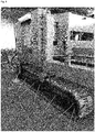
A perspective front side view of a vehicle according to the invention. As will be evident to the skilled artisan, the shown track suspension mechanisms is present at either side of the vehicle. The first (front) track frame (5) and the second (back) track frame (6) are connected to one another by means of a pivot shaft (9). Just in front of the pivot shaft, the first track frame is suspended to the suspension frame (4) by a suspension shaft (7). At the back end of the second track frame the track suspension mechanisms is suspended to the drive frame (3). -
Fig. 4 :
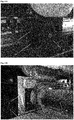
Details of the suspension frame (2) and how the suspension shaft is pivotally and slidable suspended therewith.Figure 4A is taken from the outside and shows the flanges (19) mounted to the side of the suspension shaft and preventing a lateral displacement of the suspension shaft in the opening (18) of the suspension frame.Figure 4B is taken from the inside and shows how the suspension shaft is pivotally suspended to the first track frame (5) by means of a cylindrical bushing (24) welded thereto. For a slidable fit the suspension shaft has bronze wear plates (23) in the opening (18) of the suspension frame (2). The flange at the outside can be removed to gain access to and allow replacement of the bronze wear plates. -
Fig. 5 :
Details of the pivot shaft (9), showing at either side of the first track frame (5), the shaft bearings (20). In the gap between the two track frames one can see the support arm (21) carrying the shaft and that is connected to the second track frame (6).
Claims (15)
- A vehicle (1) having a suspension frame (2), a drive frame (3) and a track chain suspension mechanism (4) characterized in that the track chain suspension mechanism (4) has a first (5) and a second track frame (6), the first frame (5) being suspended to the vehicle (1) by means of a suspension shaft (7) pivotally and slidable mounted to the suspension frame (2), the second track frame (6) pivotally connected to the vehicle (1) by means of a drive shaft (8) mounted to the drive frame (3) and wherein said first (5) and second track frame (6) are pivotally connected to one another by means of a pivot shaft (9).
- The vehicle (1) according to claim 1, wherein the track chain suspension mechanism (4) further encompasses an idler (10), track rollers (11), a drive sprocket (12) and a recoil mechanism (13).
- The vehicle (1) according to claim 2, wherein the track chain suspension mechanism (4) has only one idler (10) at the front of the first track frame (5).
- A vehicle (1) according to claims 2 or 3, wherein the drive shaft (8) is mounted below the rotation axis (22) of the idlers (10) when the track chain suspension mechanism (4) is in level position.
- A vehicle (1) according to claim 2, wherein the recoil mechanism (13) comprises a hydropneumatic cylinder (15) and a spring (16).
- A vehicle (1) according to any one of claims 1 to 5, wherein the idler (10) is rotatable mounted on bearings (17) that slidable fit in the track frame(s); in particular in the first track frame (5).
- A vehicle (1) according to any one of claims 1 to 6, wherein the suspension frame (2) comprises an opening (18); in particular a rectangular opening, to accommodate the suspension shaft (7).
- The vehicle (1) according to claim 7, wherein the suspension shaft (7) has flanges (19).
- A vehicle (1) according to claim 1, wherein the pivot shaft (9) has a shaft bearing (20) and a support arm (21).
- The vehicle (1) according to claim 9, wherein the shaft bearing (20) is mounted to the first track frame (5) and the support arm (21) is mounted to the second track frame (6).
- A vehicle (1) according to any one of claims 1 to 10, wherein the first frame (5) is about halfway suspended to the vehicle (1).
- A vehicle (1) according to any one of claims 1 to 11, wherein the second track frame (6) is connected near its rear end to the drive frame (3).
- A vehicle (1) according to any one of claims 1 to 12, wherein the first (5) and the second track frame (6) have approximately the same length.
- A vehicle (1) according to any one of claims 2 to 13, wherein the drive sprocket (12) is present at the second track frame (6).
- The vehicle (1) according to claim 14; wherein the drive sprocket (12) is present at the rear end of the second track frame (6).
Applications Claiming Priority (2)
| Application Number | Priority Date | Filing Date | Title |
|---|---|---|---|
| EP15203267 | 2015-12-31 | ||
| PCT/EP2016/082932 WO2017114954A1 (en) | 2015-12-31 | 2016-12-30 | Track chain mechanism |
Publications (2)
| Publication Number | Publication Date |
|---|---|
| EP3397542A1 EP3397542A1 (en) | 2018-11-07 |
| EP3397542B1 true EP3397542B1 (en) | 2020-01-08 |
Family
ID=55066482
Family Applications (1)
| Application Number | Title | Priority Date | Filing Date |
|---|---|---|---|
| EP16828954.4A Active EP3397542B1 (en) | 2015-12-31 | 2016-12-30 | Track chain mechanism |
Country Status (3)
| Country | Link |
|---|---|
| US (1) | US10569816B2 (en) |
| EP (1) | EP3397542B1 (en) |
| WO (1) | WO2017114954A1 (en) |
Families Citing this family (1)
| Publication number | Priority date | Publication date | Assignee | Title |
|---|---|---|---|---|
| CA3161063A1 (en) | 2021-06-02 | 2022-12-02 | Soucy International Inc. | Support structure for connecting a plurality of support wheel assemblies to a frame member of a track system and track system having the same |
Family Cites Families (20)
| Publication number | Priority date | Publication date | Assignee | Title |
|---|---|---|---|---|
| GB133392A (en) * | 1918-05-25 | |||
| US1885486A (en) * | 1929-03-19 | 1932-11-01 | William H Smyth | Convertible tractor |
| DE593618C (en) * | 1930-11-04 | 1934-03-01 | Buckau Wolf Maschf R | Crawler chassis with articulated caterpillar guide frame |
| DE591113C (en) * | 1932-04-26 | 1934-01-17 | Luebecker Maschb Ges | Articulated caterpillar guide frame |
| NL97176C (en) * | 1953-02-02 | |||
| US3446303A (en) * | 1966-06-22 | 1969-05-27 | Outboard Marine Corp | Endless track vehicle |
| US3417832A (en) * | 1966-10-24 | 1968-12-24 | William B Jaspert | Wheeled vehicle selectively convertible to endless track vehicle |
| US3447620A (en) * | 1967-08-15 | 1969-06-03 | Katrak Vehicle Co | Double walking beam suspension and drive assembly for track laying vehicles |
| US3447621A (en) * | 1967-08-15 | 1969-06-03 | Katrak Vehicle Co | Triple walking beam suspension and drive assembly for track laying vehicles |
| US3841424A (en) | 1971-12-27 | 1974-10-15 | Caterpillar Tractor Co | Triangular track resilient bogie suspension |
| FR2583701B1 (en) * | 1985-06-21 | 1990-03-23 | Commissariat Energie Atomique | VARIABLE GEOMETRY CRAWLER VEHICLE |
| DE3621137A1 (en) * | 1986-06-24 | 1988-01-07 | Fritz Seeber | CHASSIS FOR MULTI-AXLE, ALL-ROUND VEHICLES |
| US5076378A (en) | 1990-08-15 | 1991-12-31 | Lagace Jean Hugues | Vehicle with three-axle walking beams suspension |
| US5622234A (en) * | 1993-12-22 | 1997-04-22 | Deere & Company | Track suspension system and track gauge adjustment assembly |
| US5515936A (en) * | 1995-07-10 | 1996-05-14 | Vehicules Ts Bellechasse Ltee | Track tensioning system for endless track propelled vehicle |
| KR100321779B1 (en) * | 1999-12-13 | 2002-01-23 | 노수업 | Wheel and rail track driving equipment |
| FR2810009B1 (en) | 2000-06-09 | 2002-09-27 | Otico | CRAWLER DRIVE DEVICE FOR ALL-TERRAIN VEHICLE |
| WO2006128284A1 (en) * | 2005-05-31 | 2006-12-07 | Wilt H William B | Dynamically changing track support for tracked vehicle |
| US20120183383A1 (en) * | 2010-09-26 | 2012-07-19 | Rustam Stolkin | Mechanism and method of operation for polymorphic tracked vehicles such that the vehicle's weight can be spread between multiple supporting wheels |
| AT511363B1 (en) * | 2011-05-04 | 2013-01-15 | Taurob Og | CRAWLER SUSPENSION |
-
2016
- 2016-12-30 EP EP16828954.4A patent/EP3397542B1/en active Active
- 2016-12-30 WO PCT/EP2016/082932 patent/WO2017114954A1/en not_active Ceased
- 2016-12-30 US US16/066,717 patent/US10569816B2/en not_active Expired - Fee Related
Non-Patent Citations (1)
| Title |
|---|
| None * |
Also Published As
| Publication number | Publication date |
|---|---|
| US10569816B2 (en) | 2020-02-25 |
| EP3397542A1 (en) | 2018-11-07 |
| US20190009846A1 (en) | 2019-01-10 |
| WO2017114954A1 (en) | 2017-07-06 |
Similar Documents
| Publication | Publication Date | Title |
|---|---|---|
| RU2617332C2 (en) | Device in forestry machine and forestry machine, equipped with the appropriate device | |
| EP2086819B1 (en) | Suspension system for track vehicle | |
| JP4680355B2 (en) | Combine | |
| US7467831B2 (en) | Track-tightening device for crawlers | |
| RU2687400C2 (en) | Agricultural vehicle | |
| CN102120523B (en) | Slope adjusting device for middle trough of fully-mechanized scraper conveyor for thin seam | |
| CA2715027A1 (en) | Track vehicle having variable track width | |
| US20140284996A1 (en) | Idler assembly for a track roller frame | |
| US10569816B2 (en) | Track chain mechanism | |
| CN215398982U (en) | Hydraulic excavator rises and tightly installs | |
| US20050077784A1 (en) | Vehicle track with idler and roller suspension | |
| CN207774719U (en) | A kind of side-shifting distance-regulating pallet fork assembly | |
| FI20215282A1 (en) | Lavett | |
| CN103318282A (en) | Cater-pillar track chassis and caterpillar crane | |
| JP2010083242A (en) | Crawler type travel device | |
| US2792140A (en) | Material handling machine | |
| DE202007017896U1 (en) | Crawler track and crawler crane | |
| CN210537526U (en) | Harvester chassis elevating gear | |
| JP2013184660A (en) | Wheel device for guiding shock absorber for crawler | |
| JP7181500B2 (en) | vehicle carrier | |
| RU137251U1 (en) | CRAWLER ENGINE FOR CONSTRUCTION MACHINES | |
| JP4664831B2 (en) | Crawler travel device | |
| JP2004106727A (en) | Combine crawler traveling device | |
| JPH01293283A (en) | Lift device for crawler mounted travel device in crawler mounted travel vehicle | |
| JP2004256012A (en) | Crawler traveling device for work vehicles |
Legal Events
| Date | Code | Title | Description |
|---|---|---|---|
| STAA | Information on the status of an ep patent application or granted ep patent |
Free format text: STATUS: UNKNOWN |
|
| STAA | Information on the status of an ep patent application or granted ep patent |
Free format text: STATUS: THE INTERNATIONAL PUBLICATION HAS BEEN MADE |
|
| PUAI | Public reference made under article 153(3) epc to a published international application that has entered the european phase |
Free format text: ORIGINAL CODE: 0009012 |
|
| STAA | Information on the status of an ep patent application or granted ep patent |
Free format text: STATUS: REQUEST FOR EXAMINATION WAS MADE |
|
| 17P | Request for examination filed |
Effective date: 20180705 |
|
| AK | Designated contracting states |
Kind code of ref document: A1 Designated state(s): AL AT BE BG CH CY CZ DE DK EE ES FI FR GB GR HR HU IE IS IT LI LT LU LV MC MK MT NL NO PL PT RO RS SE SI SK SM TR |
|
| AX | Request for extension of the european patent |
Extension state: BA ME |
|
| DAV | Request for validation of the european patent (deleted) | ||
| DAX | Request for extension of the european patent (deleted) | ||
| GRAP | Despatch of communication of intention to grant a patent |
Free format text: ORIGINAL CODE: EPIDOSNIGR1 |
|
| STAA | Information on the status of an ep patent application or granted ep patent |
Free format text: STATUS: GRANT OF PATENT IS INTENDED |
|
| RIC1 | Information provided on ipc code assigned before grant |
Ipc: B62D 55/104 20060101ALI20190710BHEP Ipc: B62D 55/084 20060101ALI20190710BHEP Ipc: B60G 5/04 20060101ALI20190710BHEP Ipc: B60G 5/00 20060101ALI20190710BHEP Ipc: B62D 55/06 20060101AFI20190710BHEP Ipc: B62D 55/10 20060101ALI20190710BHEP Ipc: B60G 11/58 20060101ALI20190710BHEP Ipc: B62D 55/116 20060101ALI20190710BHEP |
|
| INTG | Intention to grant announced |
Effective date: 20190724 |
|
| RAP1 | Party data changed (applicant data changed or rights of an application transferred) |
Owner name: CONSULTING CASTERS FRANCOIS BVBA |
|
| GRAS | Grant fee paid |
Free format text: ORIGINAL CODE: EPIDOSNIGR3 |
|
| GRAA | (expected) grant |
Free format text: ORIGINAL CODE: 0009210 |
|
| STAA | Information on the status of an ep patent application or granted ep patent |
Free format text: STATUS: THE PATENT HAS BEEN GRANTED |
|
| AK | Designated contracting states |
Kind code of ref document: B1 Designated state(s): AL AT BE BG CH CY CZ DE DK EE ES FI FR GB GR HR HU IE IS IT LI LT LU LV MC MK MT NL NO PL PT RO RS SE SI SK SM TR |
|
| REG | Reference to a national code |
Ref country code: GB Ref legal event code: FG4D |
|
| REG | Reference to a national code |
Ref country code: CH Ref legal event code: EP |
|
| REG | Reference to a national code |
Ref country code: DE Ref legal event code: R096 Ref document number: 602016028065 Country of ref document: DE |
|
| REG | Reference to a national code |
Ref country code: IE Ref legal event code: FG4D |
|
| REG | Reference to a national code |
Ref country code: AT Ref legal event code: REF Ref document number: 1222357 Country of ref document: AT Kind code of ref document: T Effective date: 20200215 |
|
| REG | Reference to a national code |
Ref country code: NL Ref legal event code: FP |
|
| RAP2 | Party data changed (patent owner data changed or rights of a patent transferred) |
Owner name: CONSULTING CASTERS FRANCOIS BVBA |
|
| REG | Reference to a national code |
Ref country code: LT Ref legal event code: MG4D |
|
| PG25 | Lapsed in a contracting state [announced via postgrant information from national office to epo] |
Ref country code: LT Free format text: LAPSE BECAUSE OF FAILURE TO SUBMIT A TRANSLATION OF THE DESCRIPTION OR TO PAY THE FEE WITHIN THE PRESCRIBED TIME-LIMIT Effective date: 20200108 Ref country code: NO Free format text: LAPSE BECAUSE OF FAILURE TO SUBMIT A TRANSLATION OF THE DESCRIPTION OR TO PAY THE FEE WITHIN THE PRESCRIBED TIME-LIMIT Effective date: 20200408 Ref country code: PT Free format text: LAPSE BECAUSE OF FAILURE TO SUBMIT A TRANSLATION OF THE DESCRIPTION OR TO PAY THE FEE WITHIN THE PRESCRIBED TIME-LIMIT Effective date: 20200531 Ref country code: RS Free format text: LAPSE BECAUSE OF FAILURE TO SUBMIT A TRANSLATION OF THE DESCRIPTION OR TO PAY THE FEE WITHIN THE PRESCRIBED TIME-LIMIT Effective date: 20200108 Ref country code: FI Free format text: LAPSE BECAUSE OF FAILURE TO SUBMIT A TRANSLATION OF THE DESCRIPTION OR TO PAY THE FEE WITHIN THE PRESCRIBED TIME-LIMIT Effective date: 20200108 |
|
| PG25 | Lapsed in a contracting state [announced via postgrant information from national office to epo] |
Ref country code: BG Free format text: LAPSE BECAUSE OF FAILURE TO SUBMIT A TRANSLATION OF THE DESCRIPTION OR TO PAY THE FEE WITHIN THE PRESCRIBED TIME-LIMIT Effective date: 20200408 Ref country code: IS Free format text: LAPSE BECAUSE OF FAILURE TO SUBMIT A TRANSLATION OF THE DESCRIPTION OR TO PAY THE FEE WITHIN THE PRESCRIBED TIME-LIMIT Effective date: 20200508 Ref country code: GR Free format text: LAPSE BECAUSE OF FAILURE TO SUBMIT A TRANSLATION OF THE DESCRIPTION OR TO PAY THE FEE WITHIN THE PRESCRIBED TIME-LIMIT Effective date: 20200409 Ref country code: LV Free format text: LAPSE BECAUSE OF FAILURE TO SUBMIT A TRANSLATION OF THE DESCRIPTION OR TO PAY THE FEE WITHIN THE PRESCRIBED TIME-LIMIT Effective date: 20200108 Ref country code: SE Free format text: LAPSE BECAUSE OF FAILURE TO SUBMIT A TRANSLATION OF THE DESCRIPTION OR TO PAY THE FEE WITHIN THE PRESCRIBED TIME-LIMIT Effective date: 20200108 Ref country code: HR Free format text: LAPSE BECAUSE OF FAILURE TO SUBMIT A TRANSLATION OF THE DESCRIPTION OR TO PAY THE FEE WITHIN THE PRESCRIBED TIME-LIMIT Effective date: 20200108 |
|
| REG | Reference to a national code |
Ref country code: DE Ref legal event code: R097 Ref document number: 602016028065 Country of ref document: DE |
|
| PG25 | Lapsed in a contracting state [announced via postgrant information from national office to epo] |
Ref country code: ES Free format text: LAPSE BECAUSE OF FAILURE TO SUBMIT A TRANSLATION OF THE DESCRIPTION OR TO PAY THE FEE WITHIN THE PRESCRIBED TIME-LIMIT Effective date: 20200108 Ref country code: DK Free format text: LAPSE BECAUSE OF FAILURE TO SUBMIT A TRANSLATION OF THE DESCRIPTION OR TO PAY THE FEE WITHIN THE PRESCRIBED TIME-LIMIT Effective date: 20200108 Ref country code: SM Free format text: LAPSE BECAUSE OF FAILURE TO SUBMIT A TRANSLATION OF THE DESCRIPTION OR TO PAY THE FEE WITHIN THE PRESCRIBED TIME-LIMIT Effective date: 20200108 Ref country code: EE Free format text: LAPSE BECAUSE OF FAILURE TO SUBMIT A TRANSLATION OF THE DESCRIPTION OR TO PAY THE FEE WITHIN THE PRESCRIBED TIME-LIMIT Effective date: 20200108 Ref country code: CZ Free format text: LAPSE BECAUSE OF FAILURE TO SUBMIT A TRANSLATION OF THE DESCRIPTION OR TO PAY THE FEE WITHIN THE PRESCRIBED TIME-LIMIT Effective date: 20200108 Ref country code: RO Free format text: LAPSE BECAUSE OF FAILURE TO SUBMIT A TRANSLATION OF THE DESCRIPTION OR TO PAY THE FEE WITHIN THE PRESCRIBED TIME-LIMIT Effective date: 20200108 Ref country code: SK Free format text: LAPSE BECAUSE OF FAILURE TO SUBMIT A TRANSLATION OF THE DESCRIPTION OR TO PAY THE FEE WITHIN THE PRESCRIBED TIME-LIMIT Effective date: 20200108 |
|
| PLBE | No opposition filed within time limit |
Free format text: ORIGINAL CODE: 0009261 |
|
| STAA | Information on the status of an ep patent application or granted ep patent |
Free format text: STATUS: NO OPPOSITION FILED WITHIN TIME LIMIT |
|
| REG | Reference to a national code |
Ref country code: AT Ref legal event code: MK05 Ref document number: 1222357 Country of ref document: AT Kind code of ref document: T Effective date: 20200108 |
|
| 26N | No opposition filed |
Effective date: 20201009 |
|
| PG25 | Lapsed in a contracting state [announced via postgrant information from national office to epo] |
Ref country code: AT Free format text: LAPSE BECAUSE OF FAILURE TO SUBMIT A TRANSLATION OF THE DESCRIPTION OR TO PAY THE FEE WITHIN THE PRESCRIBED TIME-LIMIT Effective date: 20200108 |
|
| PG25 | Lapsed in a contracting state [announced via postgrant information from national office to epo] |
Ref country code: PL Free format text: LAPSE BECAUSE OF FAILURE TO SUBMIT A TRANSLATION OF THE DESCRIPTION OR TO PAY THE FEE WITHIN THE PRESCRIBED TIME-LIMIT Effective date: 20200108 Ref country code: SI Free format text: LAPSE BECAUSE OF FAILURE TO SUBMIT A TRANSLATION OF THE DESCRIPTION OR TO PAY THE FEE WITHIN THE PRESCRIBED TIME-LIMIT Effective date: 20200108 |
|
| REG | Reference to a national code |
Ref country code: CH Ref legal event code: PL |
|
| PG25 | Lapsed in a contracting state [announced via postgrant information from national office to epo] |
Ref country code: MC Free format text: LAPSE BECAUSE OF FAILURE TO SUBMIT A TRANSLATION OF THE DESCRIPTION OR TO PAY THE FEE WITHIN THE PRESCRIBED TIME-LIMIT Effective date: 20200108 |
|
| PG25 | Lapsed in a contracting state [announced via postgrant information from national office to epo] |
Ref country code: LU Free format text: LAPSE BECAUSE OF NON-PAYMENT OF DUE FEES Effective date: 20201230 Ref country code: IE Free format text: LAPSE BECAUSE OF NON-PAYMENT OF DUE FEES Effective date: 20201230 |
|
| PG25 | Lapsed in a contracting state [announced via postgrant information from national office to epo] |
Ref country code: CH Free format text: LAPSE BECAUSE OF NON-PAYMENT OF DUE FEES Effective date: 20201231 Ref country code: LI Free format text: LAPSE BECAUSE OF NON-PAYMENT OF DUE FEES Effective date: 20201231 |
|
| PGFP | Annual fee paid to national office [announced via postgrant information from national office to epo] |
Ref country code: GB Payment date: 20211222 Year of fee payment: 6 Ref country code: DE Payment date: 20211210 Year of fee payment: 6 Ref country code: FR Payment date: 20211224 Year of fee payment: 6 |
|
| PGFP | Annual fee paid to national office [announced via postgrant information from national office to epo] |
Ref country code: BE Payment date: 20211221 Year of fee payment: 6 |
|
| PGFP | Annual fee paid to national office [announced via postgrant information from national office to epo] |
Ref country code: NL Payment date: 20211221 Year of fee payment: 6 |
|
| PG25 | Lapsed in a contracting state [announced via postgrant information from national office to epo] |
Ref country code: TR Free format text: LAPSE BECAUSE OF FAILURE TO SUBMIT A TRANSLATION OF THE DESCRIPTION OR TO PAY THE FEE WITHIN THE PRESCRIBED TIME-LIMIT Effective date: 20200108 Ref country code: MT Free format text: LAPSE BECAUSE OF FAILURE TO SUBMIT A TRANSLATION OF THE DESCRIPTION OR TO PAY THE FEE WITHIN THE PRESCRIBED TIME-LIMIT Effective date: 20200108 Ref country code: CY Free format text: LAPSE BECAUSE OF FAILURE TO SUBMIT A TRANSLATION OF THE DESCRIPTION OR TO PAY THE FEE WITHIN THE PRESCRIBED TIME-LIMIT Effective date: 20200108 |
|
| PGFP | Annual fee paid to national office [announced via postgrant information from national office to epo] |
Ref country code: IT Payment date: 20211224 Year of fee payment: 6 |
|
| PG25 | Lapsed in a contracting state [announced via postgrant information from national office to epo] |
Ref country code: MK Free format text: LAPSE BECAUSE OF FAILURE TO SUBMIT A TRANSLATION OF THE DESCRIPTION OR TO PAY THE FEE WITHIN THE PRESCRIBED TIME-LIMIT Effective date: 20200108 Ref country code: AL Free format text: LAPSE BECAUSE OF FAILURE TO SUBMIT A TRANSLATION OF THE DESCRIPTION OR TO PAY THE FEE WITHIN THE PRESCRIBED TIME-LIMIT Effective date: 20200108 |
|
| REG | Reference to a national code |
Ref country code: DE Ref legal event code: R119 Ref document number: 602016028065 Country of ref document: DE |
|
| REG | Reference to a national code |
Ref country code: NL Ref legal event code: MM Effective date: 20230101 |
|
| GBPC | Gb: european patent ceased through non-payment of renewal fee |
Effective date: 20221230 |
|
| REG | Reference to a national code |
Ref country code: BE Ref legal event code: MM Effective date: 20221231 |
|
| PG25 | Lapsed in a contracting state [announced via postgrant information from national office to epo] |
Ref country code: NL Free format text: LAPSE BECAUSE OF NON-PAYMENT OF DUE FEES Effective date: 20230101 |
|
| PG25 | Lapsed in a contracting state [announced via postgrant information from national office to epo] |
Ref country code: GB Free format text: LAPSE BECAUSE OF NON-PAYMENT OF DUE FEES Effective date: 20221230 Ref country code: DE Free format text: LAPSE BECAUSE OF NON-PAYMENT OF DUE FEES Effective date: 20230701 |
|
| PG25 | Lapsed in a contracting state [announced via postgrant information from national office to epo] |
Ref country code: FR Free format text: LAPSE BECAUSE OF NON-PAYMENT OF DUE FEES Effective date: 20221231 Ref country code: BE Free format text: LAPSE BECAUSE OF NON-PAYMENT OF DUE FEES Effective date: 20221231 |
|
| PG25 | Lapsed in a contracting state [announced via postgrant information from national office to epo] |
Ref country code: IT Free format text: LAPSE BECAUSE OF NON-PAYMENT OF DUE FEES Effective date: 20221230 |