EP3397036A1 - Capot amélioré pour un coffre électrique et coffre électrique comportant un tel capot - Google Patents
Capot amélioré pour un coffre électrique et coffre électrique comportant un tel capot Download PDFInfo
- Publication number
- EP3397036A1 EP3397036A1 EP18169297.1A EP18169297A EP3397036A1 EP 3397036 A1 EP3397036 A1 EP 3397036A1 EP 18169297 A EP18169297 A EP 18169297A EP 3397036 A1 EP3397036 A1 EP 3397036A1
- Authority
- EP
- European Patent Office
- Prior art keywords
- flap
- opening
- hood
- cover
- electric box
- Prior art date
- Legal status (The legal status is an assumption and is not a legal conclusion. Google has not performed a legal analysis and makes no representation as to the accuracy of the status listed.)
- Granted
Links
Images

Classifications
-
- H—ELECTRICITY
- H05—ELECTRIC TECHNIQUES NOT OTHERWISE PROVIDED FOR
- H05K—PRINTED CIRCUITS; CASINGS OR CONSTRUCTIONAL DETAILS OF ELECTRIC APPARATUS; MANUFACTURE OF ASSEMBLAGES OF ELECTRICAL COMPONENTS
- H05K7/00—Constructional details common to different types of electric apparatus
- H05K7/14—Mounting supporting structure in casing or on frame or rack
- H05K7/1422—Printed circuit boards receptacles, e.g. stacked structures, electronic circuit modules or box like frames
- H05K7/1427—Housings
- H05K7/1432—Housings specially adapted for power drive units or power converters
-
- H—ELECTRICITY
- H02—GENERATION; CONVERSION OR DISTRIBUTION OF ELECTRIC POWER
- H02B—BOARDS, SUBSTATIONS OR SWITCHING ARRANGEMENTS FOR THE SUPPLY OR DISTRIBUTION OF ELECTRIC POWER
- H02B1/00—Frameworks, boards, panels, desks, casings; Details of substations or switching arrangements
- H02B1/26—Casings; Parts thereof or accessories therefor
- H02B1/28—Casings; Parts thereof or accessories therefor dustproof, splashproof, drip-proof, waterproof or flameproof
-
- H—ELECTRICITY
- H02—GENERATION; CONVERSION OR DISTRIBUTION OF ELECTRIC POWER
- H02B—BOARDS, SUBSTATIONS OR SWITCHING ARRANGEMENTS FOR THE SUPPLY OR DISTRIBUTION OF ELECTRIC POWER
- H02B13/00—Arrangement of switchgear in which switches are enclosed in, or structurally associated with, a casing, e.g. cubicle
- H02B13/02—Arrangement of switchgear in which switches are enclosed in, or structurally associated with, a casing, e.g. cubicle with metal casing
- H02B13/025—Safety arrangements, e.g. in case of excessive pressure or fire due to electrical defect
Definitions
- hoods for a trunk of the type comprising: an opening on a main wall of the hood; a movable flap which, under the effect of an overpressure inside the electrical box, is capable of pivoting between a closed position of closing the opening and an open position of fluid communication through the opening between the inside and outside the trunk.
- this type of fuse cover has a seal which is not guaranteed due to the presence of these lines of weakness.
- a cover having an opening closed by a shutter It is also known from the document US 5,878,905 , a cover having an opening closed by a shutter.
- the flap pivotally mounted on the hood, is adapted to move from a closed position to an open position under the effect of an overpressure inside the trunk.
- a jack fixed on the one hand to a wall of the trunk and on the other hand to the edge of the flap keeps the shutter in the closed position as the overpressure inside the trunk is not greater than a predetermined threshold.
- the cylinder also folds in the closed position the flap after opening and rebalancing pressures between the inside and outside of the trunk. The hood is therefore reversible.
- the reversible hood just presented has the disadvantage of leading to the evacuation of the gas stream, and possibly debris of the destroyed component, through the opening in all directions, with the risk that this gas stream is sent to a person located near the trunk (operator or passenger when such a trunk team a vehicle, including a railway vehicle).
- the invention therefore aims to solve this problem, in particular having a hood improved at least in terms of operational safety of the trunk it equips.
- the invention therefore relates to a hood for an electrical box comprising: an opening on a main wall of the hood; a movable flap which, under the effect of an overpressure inside the electrical box, is capable of pivoting between a closed position of closing the opening and an open position of fluid communication through the opening between the interior and exterior of the electric box, characterized in that an inner face of the shutter, oriented towards the inside of the electric box, is provided with a clean channel, in the open position of the shutter, to guide a gas flow from the interior of the electric box towards the outside of the electric box, the channel being inscribed in an outline of the opening to allow the movement of the shutter.
- the invention also relates to a trunk comprising a cover conforming to the cover shown above.
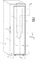
- an electrical box 1 of parallelepipedic sensitive shape is closed on one of its faces by a cover 10.
- An XYZ trihedron is associated with the chest 1.
- the cover 10 is for example mounted on a frame of the trunk 1 by means of hinge, shown schematically on the figure 1 and referenced by the number 4, allowing the hood 2 to pivot along an axis parallel to the direction X so as to allow access to the interior of the box 1, for example to install or maintain electrical components or electronic housed in the trunk 1.
- the cover 10 has a main wall 11, flat and rectangular in shape. It lies in the XY plane.
- the main wall 11 is provided with an opening 12 which, on the figure 1 , is masked by a shutter 20.
- the opening 12 passes through the main wall 11.
- the opening 12 has a substantially rectangular contour. It has a length L1 in the direction X and a width l1 in the direction Y.
- the flap 20 is mounted movably on the outer face of the main wall 11. More particularly, a first longitudinal end of the flap 20 is mounted by two hinges 21 on the outer face of the main wall 11 of the cover 10.
- the flap 20 is thus adapted to pivot about a pivot axis A extending in the direction Y.
- the flap 20 is able to move between a closed position, represented on the figure 2 , and an open position, represented on the figure 3 .
- the shutter 20 In its closed position, the shutter 20 seals the trunk 1 to isolate the inside 2 of the trunk 1 from the outside 3 of the trunk 1.
- the main wall 11 carries, on its outer surface, a raised edge 14 which surrounds the opening 12 while being received within the contour of the flap 20.
- the raised edge 14 carries a seal 40 (visible on the figure 2 ).
- a seal 40 visible on the figure 2 .
- the inner face 22 of the flap 20 oriented towards the opening 12 and the inside 2 of the box 1, bears against the seal 40 so as to seal the box 1.
- the inner face 22 of the flap 20 comprises a channel 30.
- the channel 30 is delimited transversely by a first lateral wall 33 and a second lateral wall 34.
- the first and second side walls 33, 34 are flat and fixed, for example by welding, at right angles to the inner face 22 of the flap 20.
- the first and second side walls 33, 34 are arranged parallel to one another so as to be situated at a distance d less than the width I1 of the opening 12.
- the first and second side walls 33, 34 have a trapezoidal shape.
- the length of the side walls 33, 34 (corresponding to the height of the trapezium they form) is slightly less than the length L1 of the opening 12.
- the channel 30 is adapted to be received inside the opening 12 in the closed position of the flap 20 and not to hinder the opening thereof when the occurrence of an internal overpressure 2 of the chest 1.
- the first and second side walls 33, 34 come to plug the gap laterally between the opening 12 and the lower face 22 of the flap 20.
- the maximum height of the side walls 33, 34 (corresponding to the base of the trapezium they form) is greater than the distance between the outer face of the main wall 11 and the lower face 22 of the flap 20.
- the channel 30 opens to the outside 3 of the box 1 according to an outlet port 32.
- the channel 30 puts in fluid communication the interior 2 and the outside 3 of the trunk 1, as indicated by the arrow F of the figure 3 .
- the gas flow is channeled through the opening 12 between the first and second side walls 33 and 34 to the outlet port 32. It is therefore expelled from the inside of the trunk 1 to the outside 3 of the chest 1 laterally.
- the gaseous flow is evacuated perpendicularly to the direction of the pivot axis A of the flap 20 and at a small angle with respect to the plane of the main wall 11 of the cover 10.
- the gaseous flow formed of fumes composed of various chemicals
- the debris it causes are ejected out of the trunk, laterally, in a manner that reduces the risk to the surrounding people.
- first and second side walls 33, 34 are respectively provided with arcuate slots.
- the center of these slots 35 rests on the axis A pivoting of the flap.
- the inner face of the main wall 11 of the cover 10 is provided on either side of the opening 12 of supports 36 carrying pins 37, which are adapted to cooperate with slots 35.
- a pin 37 is for example constituted by a torque screw whose tightening makes it possible to define a pressure threshold below which the flap 20 remains in its closed position and above which the flap 20 moves to move to its open position.
- the extension of the slots 35 defines the angular range of movement of the flap 20 and therefore its open position.
Landscapes
- Engineering & Computer Science (AREA)
- Power Engineering (AREA)
- Microelectronics & Electronic Packaging (AREA)
- Casings For Electric Apparatus (AREA)
- Connection Or Junction Boxes (AREA)
- Superstructure Of Vehicle (AREA)
Abstract
Description
- L'invention a pour domaine celui des capots pour un coffre électrique du type comportant : une ouverture sur une paroi principale du capot ; un volet mobile qui, sous l'effet d'une surpression à l'intérieur du coffre électrique, est capable de pivoter entre une position fermée d'obturation de l'ouverture et une position ouverte de communication fluidique à travers l'ouverture entre l'intérieur et l'extérieur du coffre électrique.
- Lors du fonctionnement d'un coffre électrique contenant des composants électriques et/ou électroniques (tels que par exemple des transistors de puissance) il peut arriver qu'un composant explose, par exemple sous l'effet d'un arc électrique ou d'une surchauffe liée à un dysfonctionnement.
- Afin de ne pas détériorer l'ensemble des composants électriques et/ou électroniques du coffre électrique, il est nécessaire de pouvoir évacuer vers l'extérieur du coffre la surpression causée par la destruction de ce composant.
- On connait un capot fusible dont la paroi principale est amincie selon des lignes de faiblesse. En cas de surpression, le capot est propre à s'ouvrir le long de ces lignes de faiblesse de manière à permettre l'évacuation vers l'extérieur du coffre du flux gazeux et éventuellement des débris du composant détruit.
- Cependant, ce type de capot fusible ne peut servir qu'une fois, puisque la déformation de sa paroi principale lors de l'ouverture n'est pas réversible. Il est donc nécessaire de remplacer le capot systématiquement après ouverture.
- Par ailleurs, ce type de capot fusible présente une étanchéité qui n'est pas garantie du fait de la présence de ces lignes de faiblesse.
- On connaît également, par le document
US 5 878 905 , un capot présentant une ouverture obturée par un volet. Le volet, monté pivotant sur le capot, est propre à passer d'une position fermée à une position ouverte sous l'effet d'une surpression à l'intérieur du coffre. Un vérin fixé d'une part à une paroi du coffre et d'autre part au bord du volet maintient le volet en position fermée tant que la surpression à l'intérieur du coffre n'est pas supérieure à un seuil prédéterminé. Le vérin permet également de rabattre en position fermée le volet après ouverture et rééquilibrage des pressions entre l'intérieur et l'extérieur du coffre. Le capot est par conséquent réversible. - Cependant, le capot réversible venant d'être présenté présente l'inconvénient de conduire à l'évacuation du flux gazeux, et éventuellement des débris du composant détruit, à travers l'ouverture dans toutes les directions, avec le risque que ce flux gazeux soit émis vers une personne située à proximité du coffre (opérateur ou passager lorsqu'un tel coffre équipe un véhicule, notamment un véhicule ferroviaire).
- L'invention a donc pour but de résoudre ce problème, en présentant notamment un capot amélioré tout au moins sur le plan de la sécurité de fonctionnement du coffre qu'il équipe.
- L'invention a donc pour objet un capot pour un coffre électrique comportant : une ouverture sur une paroi principale du capot ; un volet mobile qui, sous l'effet d'une surpression à l'intérieur du coffre électrique, est capable de pivoter entre une position fermée d'obturation de l'ouverture et une position ouverte de communication fluidique à travers l'ouverture entre l'intérieur et l'extérieur du coffre électrique, caractérisé en ce qu'une face intérieure du volet, orientée vers l'intérieur du coffre électrique, est munie d'un canal propre, en position ouverte du volet, à guider un flux gazeux depuis l'intérieur du coffre électrique vers l'extérieur du coffre électrique, le canal étant inscrit dans un contour de l'ouverture pour autoriser le déplacement du volet.
- Suivant des modes particuliers de réalisation, le capot comporte une ou plusieurs des caractéristiques suivantes, prises isolément ou suivant toutes les combinaisons techniquement possibles :
- le volet est monté pivotant sur une face externe de la paroi principale du capot (10).
- le canal comporte un orifice de sortie propre à guider le flux gazeux selon une direction principale perpendiculaire à la direction d'un axe de pivotement du volet.
- le canal comporte des première et seconde parois latérales, montées à angle droit sur la face intérieure du volet, les première et seconde parois latérales bouchant latéralement, en position ouverte du volet, un intervalle entre l'ouverture et la face inférieure du volet.
- la paroi principale du capot comporte un bord relevé entourant l'ouverture, le bord relevé portant un joint d'étanchéité et dans lequel la face intérieure du volet vient en appui du joint dans la position fermée du volet pour assurer l'étanchéité du coffre électrique.
- la première et/ou la seconde paroi latérale comporte une fente en arc de cercle, dont le centre est situé sur l'axe de pivotement du volet et dans lequel une face interne de la paroi principale du capot porte un pion reçu dans la fente pour guider en ouverture le volet.
- la fente autorise un déplacement du volet sur un intervalle angulaire prédéterminé.
- le pion est une vis dynamométrique propre à maintenir le volet en position fermée tant que la pression à l'intérieur du coffre électrique reste inférieure à une pression seuil.
- l'ouverture est sensiblement rectangulaire, un axe de pivotement du volet est parallèle à une extrémité longitudinale de l'ouverture, les première et seconde parois sont espacées l'une de l'autre d'une distance inférieure à la largeur de l'ouverture et présentent chacune une longueur légèrement inférieure à celle de l'ouverture et une hauteur, évaluée selon une direction perpendiculaire à la paroi principale du capot, supérieure ou égale à la plus grande distance entre l'ouverture et la face intérieure du volet, en position ouvert du volet.
- L'invention a également pour objet un coffre comportant un capot conforme au capot présenté ci-dessus.
- L'invention et ses avantages seront mieux compris à la lecture de la description détaillée qui va suivre d'un mode de réalisation particulier, donné uniquement à titre d'exemple illustratif et non limitatif, la description étant faite en se référant aux dessins annexés sur lesquels :
- la
figure 1 est une vue en perspective cavalière d'un coffre, dont une face est obturée par un capot selon un mode de réalisation préféré de l'invention ; - la
figure 2 est une coupe du capot selon la ligne II-II de lafigure 1 , le capot étant fermé ; et - la
figure 3 est une vue de côté du capot, celui-ci étant ouvert. - En se référant aux figures, un coffre électrique 1, de forme sensible parallélépipédique, est obturé sur l'une de ses faces par un capot 10.
- Un trièdre XYZ est associé au coffre 1.
- Le capot 10 est par exemple monté sur un bâti du coffre 1 par l'intermédiaire de charnière, représenté schématiquement sur la
figure 1 et référencé par le chiffre 4, autorisant le pivotement du capot 2 le long d'un axe parallèle à la direction X de manière à autoriser l'accès à l'intérieur du coffre 1, par exemple pour installer ou assurer la maintenance des composants électriques ou électroniques logés dans le coffre 1. - Le capot 10 comporte une paroi principale 11, plane et de forme rectangulaire. Elle repose dans le plan XY.
- La paroi principale 11 est munie d'une ouverture 12, qui, sur la
figure 1 , est masquée par un volet 20. - L'ouverture 12 traverse la paroi principale 11.
- L'ouverture 12 présente un contour sensiblement rectangulaire. Elle présente une longueur L1 selon la direction X et une largeur l1 selon la direction Y.
- Le volet 20 est monté mobile sur la face extérieure de la paroi principale 11. Plus particulièrement, une première extrémité longitudinale du volet 20 est montée par deux charnières 21 sur la face extérieure de la paroi principale 11 du capot 10.
- Le volet 20 est ainsi propre à pivoter autour d'un axe de pivotement A s'étendant selon la direction Y.
- Le volet 20 est propre à se déplacer entre une position fermée, représentée sur la
figure 2 , et une position ouverte, représentée sur lafigure 3 . - Dans sa position fermée, le volet 20 obture le coffre 1 de manière étanche pour isoler l'intérieur 2 du coffre 1 de l'extérieur 3 du coffre 1. Dans le mode de réalisation représenté ici en détail, la paroi principale 11 porte, sur sa surface extérieure, un bord relevé 14 qui entoure l'ouverture 12 tout en étant reçu à l'intérieur du contour du volet 20.
- Le bord relevé 14 porte un joint 40 (visible sur la
figure 2 ). Dans la position fermée du volet 20, la face interne 22 du volet 20, orientée vers l'ouverture 12 et l'intérieur 2 du coffre 1, vient en appui du joint 40 de manière à assurer l'étanchéité du coffre 1. - Par ailleurs, la face intérieure 22 du volet 20 comporte un canal 30.
- Le canal 30 est délimité transversalement par une première paroi latérale 33 et une seconde paroi latérale 34.
- Les première et seconde parois latérales 33, 34 sont planes et fixées, par exemple par soudage, à angle droit sur la face intérieure 22 du volet 20.
- Les première et seconde parois latérales 33, 34 sont disposées parallèlement l'une de l'autre de manière à être située à une distance d inférieure à la largeur I1 de l'ouverture 12.
- Les première et seconde parois latérales 33, 34 présentent une forme trapézoïdale. La longueur des parois latérales 33, 34 (correspondant à la hauteur du trapèze qu'elles forment) est légèrement inférieure à la longueur L1 de l'ouverture 12.
- Ainsi, le canal 30 est propre à être reçu à l'intérieur de l'ouverture 12 en position fermée du volet 20 et à ne pas gêner l'ouverture de celui-ci lors de la survenue d'une surpression à l'intérieure 2 du coffre 1.
- Comme représenté sur la
figure 3 , en position ouverte du volet 20, les première et seconde parois latérales 33, 34 viennent boucher latéralement l'intervalle entre l'ouverture 12 et la face inférieure 22 du volet 20. - La hauteur maximale des parois latérales 33, 34 (correspondant à la base du trapèze qu'elles forment) est supérieure à la distance entre la face extérieure de la paroi principale 11 et la face inférieure 22 du volet 20.
- Le canal 30 débouche à l'extérieure 3 du coffre 1 selon un orifice de sortie 32.
- Ainsi, le canal 30 met en communication fluidique l'intérieur 2 et l'extérieur 3 du coffre 1, comme l'indique la flèche F de la
figure 3 . - Ainsi, en cas de surpression, le flux gazeux est canalisé à travers l'ouverture 12 entre les première et seconde parois latérales 33 et 34 vers l'orifice de sortie 32. Il est par conséquent expulsé de l'intérieur du coffre 1 vers l'extérieur 3 du coffre 1 latéralement.
- Plus précisément, le flux gazeux est évacué perpendiculairement à la direction de l'axe A de pivotement du volet 20 et à faible angle par rapport au plan de la paroi principale 11 du capot 10.
- Ainsi, le flux gazeux (formée de fumées composées de produits chimiques variés) et éventuellement les débris qu'il entraine sont éjectés hors du coffre, latéralement, d'une manière qui permet de diminuer les risques pour les personnes environnantes.
- Comme visible sur les
figures 2 et 3 , les première et seconde parois latérales 33, 34 sont respectivement munies de fentes 35 arquées. Le centre de ces fentes 35 repose sur l'axe A de pivotement du volet. - La face intérieure de la paroi principale 11 du capot 10 est munie de part et d'autre de l'ouverture 12 de supports 36 portant des pions 37, qui sont propres à coopérer avec des fentes 35.
- Un pion 37 est par exemple constitué d'une vis dynamométrique dont le serrage permet de définir un seuil de surpression en dessous duquel le volet 20 reste dans sa position fermée et au-dessus duquel le volet 20 se déplace pour passer dans sa position ouverte.
- L'extension des fentes 35 permet de définir l'intervalle angulaire de déplacement du volet 20 et par conséquent sa position ouverte.
Claims (10)
- Capot (10) pour un coffre électrique (1), comportant :- Une ouverture (12) sur une paroi principale (11) du capot (10) ;- Un volet (20) mobile qui, sous l'effet d'une surpression à l'intérieur (2) du coffre électrique (1), est capable de pivoter entre une position fermée d'obturation de l'ouverture (12) et une position ouverte de communication fluidique à travers l'ouverture (12) entre l'intérieur (2) et l'extérieur (3) du coffre électrique (1),caractérisé en ce qu'une face intérieure (22) du volet (20), orientée vers l'intérieur (2) du coffre électrique (1), est munie d'un canal (30) propre, en position ouverte du volet, à guider un flux gazeux depuis l'intérieur (2) du coffre électrique (1) vers l'extérieur (3) du coffre électrique (1), le canal (30) étant inscrit dans un contour de l'ouverture (12) pour autoriser le déplacement du volet (20).
- Capot (10) selon la revendication 1, dans lequel le volet (20) est monté pivotant sur une face externe de la paroi principale (11) du capot (10).
- Capot (10) selon la revendication 1 ou 2, dans lequel le canal (30) comporte un orifice de sortie (32) propre à guider le flux gazeux selon une direction principale (X) perpendiculaire à la direction d'un axe (A) de pivotement du volet (20).
- Capot (10) selon la revendication 3, dans lequel le canal (30) comporte des première et seconde parois latérales (33, 34), montées à angle droit sur la face intérieure (22) du volet (20), les première et seconde parois latérales bouchant latéralement, en position ouverte du volet (20), un intervalle entre l'ouverture (12) et la face inférieure (22) du volet (20).
- Capot (10) selon l'une quelconque des revendications 1 à 4, dans lequel la paroi principale (11) du capot (10) comporte un bord relevé (14) entourant l'ouverture (12), le bord relevé (14) portant un joint d'étanchéité (40), et dans lequel la face intérieure (22) du volet (20) vient en appui du joint (40) dans la position fermée du volet (20) pour assurer l'étanchéité du coffre électrique (1).
- Capot (10) selon la revendication 4, dans lequel la première et/ou la seconde paroi latérale (33, 34) comporte une fente (35, 36) en arc de cercle, dont le centre est situé sur l'axe (A) de pivotement du volet (20) et dans lequel une face interne de la paroi principale (11) du capot (10) porte un pion (37, 38) reçu dans la fente pour guider en ouverture le volet (20).
- Capot (10) selon la revendication 6, dans lequel la fente (35, 36) autorise un déplacement du volet (20) sur un intervalle angulaire prédéterminé.
- Capot (10) selon la revendication 6 ou 7, dans lequel le pion (38, 38) est une vis dynamométrique propre à maintenir le volet (20) en position fermée tant que la pression à l'intérieur du coffre électrique (1) reste inférieure à une pression seuil.
- Capot (10) selon l'une quelconque des revendications 1 à 8, dans lequel l'ouverture (12) est sensiblement rectangulaire, un axe (A) de pivotement du volet (20) est parallèle à une extrémité longitudinale de l'ouverture (12), les première et seconde parois (33, 34) sont espacées l'une de l'autre d'une distance inférieure à la largeur de l'ouverture (12) et présentent chacune une longueur légèrement inférieure à celle de l'ouverture (12) et une hauteur, évaluée selon une direction perpendiculaire à la paroi principale (11) du capot (10), supérieure ou égale à la plus grande distance entre l'ouverture (12) et la face intérieure (22) du volet (20), en position ouvert du volet.
- Coffre électrique (1), caractérisé en ce qu'il comporte un capot conforme au capot (10) selon l'une quelconque des revendications 1 à 9.
Applications Claiming Priority (1)
| Application Number | Priority Date | Filing Date | Title |
|---|---|---|---|
| FR1753574A FR3065618B1 (fr) | 2017-04-25 | 2017-04-25 | Capot ameliore pour un coffre electrique et coffre electrique comportant un tel capot |
Publications (2)
| Publication Number | Publication Date |
|---|---|
| EP3397036A1 true EP3397036A1 (fr) | 2018-10-31 |
| EP3397036B1 EP3397036B1 (fr) | 2021-08-11 |
Family
ID=59297047
Family Applications (1)
| Application Number | Title | Priority Date | Filing Date |
|---|---|---|---|
| EP18169297.1A Active EP3397036B1 (fr) | 2017-04-25 | 2018-04-25 | Capot amélioré pour un coffre électrique et coffre électrique comportant un tel capot |
Country Status (2)
| Country | Link |
|---|---|
| EP (1) | EP3397036B1 (fr) |
| FR (1) | FR3065618B1 (fr) |
Citations (5)
| Publication number | Priority date | Publication date | Assignee | Title |
|---|---|---|---|---|
| DE1059079B (de) * | 1957-05-07 | 1959-06-11 | Licentia Gmbh | Hochspannungsschaltanlage in gekapselter Bauform |
| DE1201448B (de) * | 1959-09-26 | 1965-09-23 | Siemens Ag | Druckentlastungsklappe fuer Schaltzellen |
| DE3840240A1 (de) * | 1988-11-29 | 1990-05-31 | Elef Svenska Elverkens Ekonomi | Druckentlastungseinrichtung an gebaeuden, insbesondere elektrischen schaltwerken |
| US5878905A (en) * | 1996-08-29 | 1999-03-09 | Abb Patent Gmbh | Container-type switchgear |
| DE102013208831B3 (de) * | 2013-05-14 | 2014-06-18 | Siemens Aktiengesellschaft | Elektrische Anlage, insbesondere Mittelspannungsschaltanlage |
-
2017
- 2017-04-25 FR FR1753574A patent/FR3065618B1/fr not_active Expired - Fee Related
-
2018
- 2018-04-25 EP EP18169297.1A patent/EP3397036B1/fr active Active
Patent Citations (5)
| Publication number | Priority date | Publication date | Assignee | Title |
|---|---|---|---|---|
| DE1059079B (de) * | 1957-05-07 | 1959-06-11 | Licentia Gmbh | Hochspannungsschaltanlage in gekapselter Bauform |
| DE1201448B (de) * | 1959-09-26 | 1965-09-23 | Siemens Ag | Druckentlastungsklappe fuer Schaltzellen |
| DE3840240A1 (de) * | 1988-11-29 | 1990-05-31 | Elef Svenska Elverkens Ekonomi | Druckentlastungseinrichtung an gebaeuden, insbesondere elektrischen schaltwerken |
| US5878905A (en) * | 1996-08-29 | 1999-03-09 | Abb Patent Gmbh | Container-type switchgear |
| DE102013208831B3 (de) * | 2013-05-14 | 2014-06-18 | Siemens Aktiengesellschaft | Elektrische Anlage, insbesondere Mittelspannungsschaltanlage |
Also Published As
| Publication number | Publication date |
|---|---|
| FR3065618B1 (fr) | 2019-12-20 |
| EP3397036B1 (fr) | 2021-08-11 |
| FR3065618A1 (fr) | 2018-10-26 |
Similar Documents
| Publication | Publication Date | Title |
|---|---|---|
| FR3066441A1 (fr) | Dispositif de sortie | |
| EP2463614A1 (fr) | Dispositif de protection balistique déportée | |
| FR2968391A1 (fr) | Dispositif de protection balistique deportee destine a couvrir completement une porte | |
| FR3071459A1 (fr) | Element de carrosserie a rangement securise | |
| EP3397036B1 (fr) | Capot amélioré pour un coffre électrique et coffre électrique comportant un tel capot | |
| EP2762265A1 (fr) | Cabine de protection contre un rayonnement électromagnétique, par exemple un rayonnement laser | |
| FR2955883A1 (fr) | Cadre pour le montage d'un volet dans une installation aeraulique notamment de desenfumage | |
| EP3222448B1 (fr) | Dispositif de distribution d'air pour tourelle | |
| FR2800759A1 (fr) | Dispositif de degondage assiste, avec sa lisse, pour barriere | |
| EP2128367B1 (fr) | Ensemble pour la fermeture d'une ouverture d'accès à un volume de stockage d'un engin de transport | |
| FR2898632A1 (fr) | Dispositif anti-pincement pour une porte battante d'un vehicule automobile et vehicule automobile comportant au moins une porte equipee d'un tel dispositif anti-pincement. | |
| FR3071821B1 (fr) | Turboreacteur double flux pour un aeronef avec une ouverture amelioree | |
| EP1705060B1 (fr) | Dispositif d'obturation d'ouverture de boîtier de dispositif d'éclairage pour véhicule automobile | |
| EP1574768B1 (fr) | Objet gonflable muni de moyens formant valve de gonflage/dégonflage | |
| FR2942263A1 (fr) | Dispositif d'ouverture/fermeture a double charniere | |
| FR3006358A1 (fr) | Dispositif d'isolation laterale de porte sectionnelle | |
| FR3147617A1 (fr) | Dispositif pare-flammes comprenant un dispositif de dépressurisation | |
| FR3113093A1 (fr) | Systeme de propulsion d’un aeronef comportant un systeme d’etancheite ameliore | |
| FR2950090A1 (fr) | Exutoire de fumee | |
| FR2830000A1 (fr) | Conteneur | |
| EP2447581A1 (fr) | Dispositif de protection pour un volet de recirculation des gaz d'echappement | |
| FR2843032A1 (fr) | Dispositif d'obturation d'un conduit de ventilation, notamment clapet coupe-feu ou volet de desenfumage | |
| CA2762059C (fr) | Dispositif de protection balistique deportee | |
| FR3152501A1 (fr) | Obturateur étanche d’un orifice de boitier protégé contre les champs électromagnétiques | |
| WO2016107835A1 (fr) | Systeme de transfert etanche a portes coulissantes entre une enceinte et un conteneur |
Legal Events
| Date | Code | Title | Description |
|---|---|---|---|
| PUAI | Public reference made under article 153(3) epc to a published international application that has entered the european phase |
Free format text: ORIGINAL CODE: 0009012 |
|
| STAA | Information on the status of an ep patent application or granted ep patent |
Free format text: STATUS: THE APPLICATION HAS BEEN PUBLISHED |
|
| AK | Designated contracting states |
Kind code of ref document: A1 Designated state(s): AL AT BE BG CH CY CZ DE DK EE ES FI FR GB GR HR HU IE IS IT LI LT LU LV MC MK MT NL NO PL PT RO RS SE SI SK SM TR |
|
| AX | Request for extension of the european patent |
Extension state: BA ME |
|
| STAA | Information on the status of an ep patent application or granted ep patent |
Free format text: STATUS: REQUEST FOR EXAMINATION WAS MADE |
|
| 17P | Request for examination filed |
Effective date: 20190401 |
|
| RBV | Designated contracting states (corrected) |
Designated state(s): AL AT BE BG CH CY CZ DE DK EE ES FI FR GB GR HR HU IE IS IT LI LT LU LV MC MK MT NL NO PL PT RO RS SE SI SK SM TR |
|
| GRAP | Despatch of communication of intention to grant a patent |
Free format text: ORIGINAL CODE: EPIDOSNIGR1 |
|
| STAA | Information on the status of an ep patent application or granted ep patent |
Free format text: STATUS: GRANT OF PATENT IS INTENDED |
|
| RIC1 | Information provided on ipc code assigned before grant |
Ipc: H02B 1/28 20060101ALI20210219BHEP Ipc: H02B 13/025 20060101ALI20210219BHEP Ipc: H05K 7/14 20060101AFI20210219BHEP |
|
| INTG | Intention to grant announced |
Effective date: 20210331 |
|
| GRAS | Grant fee paid |
Free format text: ORIGINAL CODE: EPIDOSNIGR3 |
|
| GRAA | (expected) grant |
Free format text: ORIGINAL CODE: 0009210 |
|
| STAA | Information on the status of an ep patent application or granted ep patent |
Free format text: STATUS: THE PATENT HAS BEEN GRANTED |
|
| AK | Designated contracting states |
Kind code of ref document: B1 Designated state(s): AL AT BE BG CH CY CZ DE DK EE ES FI FR GB GR HR HU IE IS IT LI LT LU LV MC MK MT NL NO PL PT RO RS SE SI SK SM TR |
|
| REG | Reference to a national code |
Ref country code: CH Ref legal event code: EP |
|
| REG | Reference to a national code |
Ref country code: DE Ref legal event code: R096 Ref document number: 602018021472 Country of ref document: DE |
|
| REG | Reference to a national code |
Ref country code: IE Ref legal event code: FG4D Free format text: LANGUAGE OF EP DOCUMENT: FRENCH Ref country code: AT Ref legal event code: REF Ref document number: 1420763 Country of ref document: AT Kind code of ref document: T Effective date: 20210915 |
|
| REG | Reference to a national code |
Ref country code: LT Ref legal event code: MG9D |
|
| REG | Reference to a national code |
Ref country code: NL Ref legal event code: MP Effective date: 20210811 |
|
| REG | Reference to a national code |
Ref country code: AT Ref legal event code: MK05 Ref document number: 1420763 Country of ref document: AT Kind code of ref document: T Effective date: 20210811 |
|
| PG25 | Lapsed in a contracting state [announced via postgrant information from national office to epo] |
Ref country code: LT Free format text: LAPSE BECAUSE OF FAILURE TO SUBMIT A TRANSLATION OF THE DESCRIPTION OR TO PAY THE FEE WITHIN THE PRESCRIBED TIME-LIMIT Effective date: 20210811 Ref country code: BG Free format text: LAPSE BECAUSE OF FAILURE TO SUBMIT A TRANSLATION OF THE DESCRIPTION OR TO PAY THE FEE WITHIN THE PRESCRIBED TIME-LIMIT Effective date: 20211111 Ref country code: AT Free format text: LAPSE BECAUSE OF FAILURE TO SUBMIT A TRANSLATION OF THE DESCRIPTION OR TO PAY THE FEE WITHIN THE PRESCRIBED TIME-LIMIT Effective date: 20210811 Ref country code: PT Free format text: LAPSE BECAUSE OF FAILURE TO SUBMIT A TRANSLATION OF THE DESCRIPTION OR TO PAY THE FEE WITHIN THE PRESCRIBED TIME-LIMIT Effective date: 20211213 Ref country code: NO Free format text: LAPSE BECAUSE OF FAILURE TO SUBMIT A TRANSLATION OF THE DESCRIPTION OR TO PAY THE FEE WITHIN THE PRESCRIBED TIME-LIMIT Effective date: 20211111 Ref country code: FI Free format text: LAPSE BECAUSE OF FAILURE TO SUBMIT A TRANSLATION OF THE DESCRIPTION OR TO PAY THE FEE WITHIN THE PRESCRIBED TIME-LIMIT Effective date: 20210811 Ref country code: ES Free format text: LAPSE BECAUSE OF FAILURE TO SUBMIT A TRANSLATION OF THE DESCRIPTION OR TO PAY THE FEE WITHIN THE PRESCRIBED TIME-LIMIT Effective date: 20210811 Ref country code: HR Free format text: LAPSE BECAUSE OF FAILURE TO SUBMIT A TRANSLATION OF THE DESCRIPTION OR TO PAY THE FEE WITHIN THE PRESCRIBED TIME-LIMIT Effective date: 20210811 Ref country code: RS Free format text: LAPSE BECAUSE OF FAILURE TO SUBMIT A TRANSLATION OF THE DESCRIPTION OR TO PAY THE FEE WITHIN THE PRESCRIBED TIME-LIMIT Effective date: 20210811 Ref country code: SE Free format text: LAPSE BECAUSE OF FAILURE TO SUBMIT A TRANSLATION OF THE DESCRIPTION OR TO PAY THE FEE WITHIN THE PRESCRIBED TIME-LIMIT Effective date: 20210811 |
|
| PG25 | Lapsed in a contracting state [announced via postgrant information from national office to epo] |
Ref country code: PL Free format text: LAPSE BECAUSE OF FAILURE TO SUBMIT A TRANSLATION OF THE DESCRIPTION OR TO PAY THE FEE WITHIN THE PRESCRIBED TIME-LIMIT Effective date: 20210811 Ref country code: LV Free format text: LAPSE BECAUSE OF FAILURE TO SUBMIT A TRANSLATION OF THE DESCRIPTION OR TO PAY THE FEE WITHIN THE PRESCRIBED TIME-LIMIT Effective date: 20210811 Ref country code: GR Free format text: LAPSE BECAUSE OF FAILURE TO SUBMIT A TRANSLATION OF THE DESCRIPTION OR TO PAY THE FEE WITHIN THE PRESCRIBED TIME-LIMIT Effective date: 20211112 |
|
| PG25 | Lapsed in a contracting state [announced via postgrant information from national office to epo] |
Ref country code: NL Free format text: LAPSE BECAUSE OF FAILURE TO SUBMIT A TRANSLATION OF THE DESCRIPTION OR TO PAY THE FEE WITHIN THE PRESCRIBED TIME-LIMIT Effective date: 20210811 |
|
| PG25 | Lapsed in a contracting state [announced via postgrant information from national office to epo] |
Ref country code: DK Free format text: LAPSE BECAUSE OF FAILURE TO SUBMIT A TRANSLATION OF THE DESCRIPTION OR TO PAY THE FEE WITHIN THE PRESCRIBED TIME-LIMIT Effective date: 20210811 |
|
| REG | Reference to a national code |
Ref country code: DE Ref legal event code: R097 Ref document number: 602018021472 Country of ref document: DE |
|
| PG25 | Lapsed in a contracting state [announced via postgrant information from national office to epo] |
Ref country code: SM Free format text: LAPSE BECAUSE OF FAILURE TO SUBMIT A TRANSLATION OF THE DESCRIPTION OR TO PAY THE FEE WITHIN THE PRESCRIBED TIME-LIMIT Effective date: 20210811 Ref country code: SK Free format text: LAPSE BECAUSE OF FAILURE TO SUBMIT A TRANSLATION OF THE DESCRIPTION OR TO PAY THE FEE WITHIN THE PRESCRIBED TIME-LIMIT Effective date: 20210811 Ref country code: RO Free format text: LAPSE BECAUSE OF FAILURE TO SUBMIT A TRANSLATION OF THE DESCRIPTION OR TO PAY THE FEE WITHIN THE PRESCRIBED TIME-LIMIT Effective date: 20210811 Ref country code: EE Free format text: LAPSE BECAUSE OF FAILURE TO SUBMIT A TRANSLATION OF THE DESCRIPTION OR TO PAY THE FEE WITHIN THE PRESCRIBED TIME-LIMIT Effective date: 20210811 Ref country code: CZ Free format text: LAPSE BECAUSE OF FAILURE TO SUBMIT A TRANSLATION OF THE DESCRIPTION OR TO PAY THE FEE WITHIN THE PRESCRIBED TIME-LIMIT Effective date: 20210811 Ref country code: AL Free format text: LAPSE BECAUSE OF FAILURE TO SUBMIT A TRANSLATION OF THE DESCRIPTION OR TO PAY THE FEE WITHIN THE PRESCRIBED TIME-LIMIT Effective date: 20210811 |
|
| PLBE | No opposition filed within time limit |
Free format text: ORIGINAL CODE: 0009261 |
|
| STAA | Information on the status of an ep patent application or granted ep patent |
Free format text: STATUS: NO OPPOSITION FILED WITHIN TIME LIMIT |
|
| 26N | No opposition filed |
Effective date: 20220512 |
|
| PG25 | Lapsed in a contracting state [announced via postgrant information from national office to epo] |
Ref country code: SI Free format text: LAPSE BECAUSE OF FAILURE TO SUBMIT A TRANSLATION OF THE DESCRIPTION OR TO PAY THE FEE WITHIN THE PRESCRIBED TIME-LIMIT Effective date: 20210811 |
|
| REG | Reference to a national code |
Ref country code: CH Ref legal event code: PL |
|
| REG | Reference to a national code |
Ref country code: BE Ref legal event code: MM Effective date: 20220430 |
|
| PG25 | Lapsed in a contracting state [announced via postgrant information from national office to epo] |
Ref country code: MC Free format text: LAPSE BECAUSE OF FAILURE TO SUBMIT A TRANSLATION OF THE DESCRIPTION OR TO PAY THE FEE WITHIN THE PRESCRIBED TIME-LIMIT Effective date: 20210811 Ref country code: LU Free format text: LAPSE BECAUSE OF NON-PAYMENT OF DUE FEES Effective date: 20220425 Ref country code: LI Free format text: LAPSE BECAUSE OF NON-PAYMENT OF DUE FEES Effective date: 20220430 Ref country code: CH Free format text: LAPSE BECAUSE OF NON-PAYMENT OF DUE FEES Effective date: 20220430 |
|
| PG25 | Lapsed in a contracting state [announced via postgrant information from national office to epo] |
Ref country code: BE Free format text: LAPSE BECAUSE OF NON-PAYMENT OF DUE FEES Effective date: 20220430 |
|
| PG25 | Lapsed in a contracting state [announced via postgrant information from national office to epo] |
Ref country code: IE Free format text: LAPSE BECAUSE OF NON-PAYMENT OF DUE FEES Effective date: 20220425 |
|
| P01 | Opt-out of the competence of the unified patent court (upc) registered |
Effective date: 20230823 |
|
| PG25 | Lapsed in a contracting state [announced via postgrant information from national office to epo] |
Ref country code: HU Free format text: LAPSE BECAUSE OF FAILURE TO SUBMIT A TRANSLATION OF THE DESCRIPTION OR TO PAY THE FEE WITHIN THE PRESCRIBED TIME-LIMIT; INVALID AB INITIO Effective date: 20180425 |
|
| PG25 | Lapsed in a contracting state [announced via postgrant information from national office to epo] |
Ref country code: MK Free format text: LAPSE BECAUSE OF FAILURE TO SUBMIT A TRANSLATION OF THE DESCRIPTION OR TO PAY THE FEE WITHIN THE PRESCRIBED TIME-LIMIT Effective date: 20210811 Ref country code: CY Free format text: LAPSE BECAUSE OF FAILURE TO SUBMIT A TRANSLATION OF THE DESCRIPTION OR TO PAY THE FEE WITHIN THE PRESCRIBED TIME-LIMIT Effective date: 20210811 |
|
| PG25 | Lapsed in a contracting state [announced via postgrant information from national office to epo] |
Ref country code: MT Free format text: LAPSE BECAUSE OF FAILURE TO SUBMIT A TRANSLATION OF THE DESCRIPTION OR TO PAY THE FEE WITHIN THE PRESCRIBED TIME-LIMIT Effective date: 20210811 |
|
| REG | Reference to a national code |
Ref country code: GB Ref legal event code: 732E Free format text: REGISTERED BETWEEN 20250213 AND 20250219 |
|
| PGFP | Annual fee paid to national office [announced via postgrant information from national office to epo] |
Ref country code: DE Payment date: 20250422 Year of fee payment: 8 |
|
| PGFP | Annual fee paid to national office [announced via postgrant information from national office to epo] |
Ref country code: IT Payment date: 20250424 Year of fee payment: 8 |
|
| PGFP | Annual fee paid to national office [announced via postgrant information from national office to epo] |
Ref country code: FR Payment date: 20250425 Year of fee payment: 8 |
|
| PG25 | Lapsed in a contracting state [announced via postgrant information from national office to epo] |
Ref country code: TR Free format text: LAPSE BECAUSE OF FAILURE TO SUBMIT A TRANSLATION OF THE DESCRIPTION OR TO PAY THE FEE WITHIN THE PRESCRIBED TIME-LIMIT Effective date: 20210811 |
|
| PGFP | Annual fee paid to national office [announced via postgrant information from national office to epo] |
Ref country code: GB Payment date: 20260306 Year of fee payment: 9 |