EP3396201B1 - Friktionsantriebsriemen - Google Patents
Friktionsantriebsriemen Download PDFInfo
- Publication number
- EP3396201B1 EP3396201B1 EP16878673.9A EP16878673A EP3396201B1 EP 3396201 B1 EP3396201 B1 EP 3396201B1 EP 16878673 A EP16878673 A EP 16878673A EP 3396201 B1 EP3396201 B1 EP 3396201B1
- Authority
- EP
- European Patent Office
- Prior art keywords
- rubber
- power transmission
- belt
- rubber layer
- mass
- Prior art date
- Legal status (The legal status is an assumption and is not a legal conclusion. Google has not performed a legal analysis and makes no representation as to the accuracy of the status listed.)
- Active
Links
Images


Classifications
-
- F—MECHANICAL ENGINEERING; LIGHTING; HEATING; WEAPONS; BLASTING
- F16—ENGINEERING ELEMENTS AND UNITS; GENERAL MEASURES FOR PRODUCING AND MAINTAINING EFFECTIVE FUNCTIONING OF MACHINES OR INSTALLATIONS; THERMAL INSULATION IN GENERAL
- F16G—BELTS, CABLES, OR ROPES, PREDOMINANTLY USED FOR DRIVING PURPOSES; CHAINS; FITTINGS PREDOMINANTLY USED THEREFOR
- F16G5/00—V-belts, i.e. belts of tapered cross-section
- F16G5/04—V-belts, i.e. belts of tapered cross-section made of rubber
- F16G5/06—V-belts, i.e. belts of tapered cross-section made of rubber with reinforcement bonded by the rubber
-
- C—CHEMISTRY; METALLURGY
- C08—ORGANIC MACROMOLECULAR COMPOUNDS; THEIR PREPARATION OR CHEMICAL WORKING-UP; COMPOSITIONS BASED THEREON
- C08K—Use of inorganic or non-macromolecular organic substances as compounding ingredients
- C08K3/00—Use of inorganic substances as compounding ingredients
- C08K3/02—Elements
- C08K3/04—Carbon
-
- C—CHEMISTRY; METALLURGY
- C08—ORGANIC MACROMOLECULAR COMPOUNDS; THEIR PREPARATION OR CHEMICAL WORKING-UP; COMPOSITIONS BASED THEREON
- C08K—Use of inorganic or non-macromolecular organic substances as compounding ingredients
- C08K3/00—Use of inorganic substances as compounding ingredients
- C08K3/34—Silicon-containing compounds
- C08K3/36—Silica
-
- C—CHEMISTRY; METALLURGY
- C08—ORGANIC MACROMOLECULAR COMPOUNDS; THEIR PREPARATION OR CHEMICAL WORKING-UP; COMPOSITIONS BASED THEREON
- C08K—Use of inorganic or non-macromolecular organic substances as compounding ingredients
- C08K7/00—Use of ingredients characterised by shape
- C08K7/02—Fibres or whiskers
-
- C—CHEMISTRY; METALLURGY
- C08—ORGANIC MACROMOLECULAR COMPOUNDS; THEIR PREPARATION OR CHEMICAL WORKING-UP; COMPOSITIONS BASED THEREON
- C08L—COMPOSITIONS OF MACROMOLECULAR COMPOUNDS
- C08L11/00—Compositions of homopolymers or copolymers of chloroprene
-
- C—CHEMISTRY; METALLURGY
- C08—ORGANIC MACROMOLECULAR COMPOUNDS; THEIR PREPARATION OR CHEMICAL WORKING-UP; COMPOSITIONS BASED THEREON
- C08L—COMPOSITIONS OF MACROMOLECULAR COMPOUNDS
- C08L9/00—Compositions of homopolymers or copolymers of conjugated diene hydrocarbons
-
- F—MECHANICAL ENGINEERING; LIGHTING; HEATING; WEAPONS; BLASTING
- F16—ENGINEERING ELEMENTS AND UNITS; GENERAL MEASURES FOR PRODUCING AND MAINTAINING EFFECTIVE FUNCTIONING OF MACHINES OR INSTALLATIONS; THERMAL INSULATION IN GENERAL
- F16G—BELTS, CABLES, OR ROPES, PREDOMINANTLY USED FOR DRIVING PURPOSES; CHAINS; FITTINGS PREDOMINANTLY USED THEREFOR
- F16G5/00—V-belts, i.e. belts of tapered cross-section
- F16G5/04—V-belts, i.e. belts of tapered cross-section made of rubber
- F16G5/06—V-belts, i.e. belts of tapered cross-section made of rubber with reinforcement bonded by the rubber
- F16G5/08—V-belts, i.e. belts of tapered cross-section made of rubber with reinforcement bonded by the rubber with textile reinforcement
-
- F—MECHANICAL ENGINEERING; LIGHTING; HEATING; WEAPONS; BLASTING
- F16—ENGINEERING ELEMENTS AND UNITS; GENERAL MEASURES FOR PRODUCING AND MAINTAINING EFFECTIVE FUNCTIONING OF MACHINES OR INSTALLATIONS; THERMAL INSULATION IN GENERAL
- F16G—BELTS, CABLES, OR ROPES, PREDOMINANTLY USED FOR DRIVING PURPOSES; CHAINS; FITTINGS PREDOMINANTLY USED THEREFOR
- F16G5/00—V-belts, i.e. belts of tapered cross-section
- F16G5/20—V-belts, i.e. belts of tapered cross-section with a contact surface of special shape, e.g. toothed
-
- C—CHEMISTRY; METALLURGY
- C08—ORGANIC MACROMOLECULAR COMPOUNDS; THEIR PREPARATION OR CHEMICAL WORKING-UP; COMPOSITIONS BASED THEREON
- C08F—MACROMOLECULAR COMPOUNDS OBTAINED BY REACTIONS ONLY INVOLVING CARBON-TO-CARBON UNSATURATED BONDS
- C08F36/00—Homopolymers and copolymers of compounds having one or more unsaturated aliphatic radicals, at least one having two or more carbon-to-carbon double bonds
- C08F36/02—Homopolymers and copolymers of compounds having one or more unsaturated aliphatic radicals, at least one having two or more carbon-to-carbon double bonds the radical having only two carbon-to-carbon double bonds
- C08F36/04—Homopolymers and copolymers of compounds having one or more unsaturated aliphatic radicals, at least one having two or more carbon-to-carbon double bonds the radical having only two carbon-to-carbon double bonds conjugated
- C08F36/14—Homopolymers and copolymers of compounds having one or more unsaturated aliphatic radicals, at least one having two or more carbon-to-carbon double bonds the radical having only two carbon-to-carbon double bonds conjugated containing elements other than carbon and hydrogen
- C08F36/16—Homopolymers and copolymers of compounds having one or more unsaturated aliphatic radicals, at least one having two or more carbon-to-carbon double bonds the radical having only two carbon-to-carbon double bonds conjugated containing elements other than carbon and hydrogen containing halogen
- C08F36/18—Homopolymers and copolymers of compounds having one or more unsaturated aliphatic radicals, at least one having two or more carbon-to-carbon double bonds the radical having only two carbon-to-carbon double bonds conjugated containing elements other than carbon and hydrogen containing halogen containing chlorine
-
- C—CHEMISTRY; METALLURGY
- C08—ORGANIC MACROMOLECULAR COMPOUNDS; THEIR PREPARATION OR CHEMICAL WORKING-UP; COMPOSITIONS BASED THEREON
- C08L—COMPOSITIONS OF MACROMOLECULAR COMPOUNDS
- C08L2203/00—Applications
- C08L2203/12—Applications used for fibers
-
- C—CHEMISTRY; METALLURGY
- C08—ORGANIC MACROMOLECULAR COMPOUNDS; THEIR PREPARATION OR CHEMICAL WORKING-UP; COMPOSITIONS BASED THEREON
- C08L—COMPOSITIONS OF MACROMOLECULAR COMPOUNDS
- C08L2205/00—Polymer mixtures characterised by other features
- C08L2205/14—Polymer mixtures characterised by other features containing polymeric additives characterised by shape
- C08L2205/16—Fibres; Fibrils
-
- C—CHEMISTRY; METALLURGY
- C08—ORGANIC MACROMOLECULAR COMPOUNDS; THEIR PREPARATION OR CHEMICAL WORKING-UP; COMPOSITIONS BASED THEREON
- C08L—COMPOSITIONS OF MACROMOLECULAR COMPOUNDS
- C08L61/00—Compositions of condensation polymers of aldehydes or ketones; Compositions of derivatives of such polymers
- C08L61/04—Condensation polymers of aldehydes or ketones with phenols only
- C08L61/06—Condensation polymers of aldehydes or ketones with phenols only of aldehydes with phenols
- C08L61/12—Condensation polymers of aldehydes or ketones with phenols only of aldehydes with phenols with polyhydric phenols
-
- C—CHEMISTRY; METALLURGY
- C08—ORGANIC MACROMOLECULAR COMPOUNDS; THEIR PREPARATION OR CHEMICAL WORKING-UP; COMPOSITIONS BASED THEREON
- C08L—COMPOSITIONS OF MACROMOLECULAR COMPOUNDS
- C08L61/00—Compositions of condensation polymers of aldehydes or ketones; Compositions of derivatives of such polymers
- C08L61/20—Condensation polymers of aldehydes or ketones with only compounds containing hydrogen attached to nitrogen
- C08L61/26—Condensation polymers of aldehydes or ketones with only compounds containing hydrogen attached to nitrogen of aldehydes with heterocyclic compounds
- C08L61/28—Condensation polymers of aldehydes or ketones with only compounds containing hydrogen attached to nitrogen of aldehydes with heterocyclic compounds with melamine
-
- C—CHEMISTRY; METALLURGY
- C08—ORGANIC MACROMOLECULAR COMPOUNDS; THEIR PREPARATION OR CHEMICAL WORKING-UP; COMPOSITIONS BASED THEREON
- C08L—COMPOSITIONS OF MACROMOLECULAR COMPOUNDS
- C08L77/00—Compositions of polyamides obtained by reactions forming a carboxylic amide link in the main chain; Compositions of derivatives of such polymers
- C08L77/10—Polyamides derived from aromatically bound amino and carboxyl groups of amino-carboxylic acids or of polyamines and polycarboxylic acids
-
- C—CHEMISTRY; METALLURGY
- C08—ORGANIC MACROMOLECULAR COMPOUNDS; THEIR PREPARATION OR CHEMICAL WORKING-UP; COMPOSITIONS BASED THEREON
- C08L—COMPOSITIONS OF MACROMOLECULAR COMPOUNDS
- C08L79/00—Compositions of macromolecular compounds obtained by reactions forming in the main chain of the macromolecule a linkage containing nitrogen with or without oxygen or carbon only, not provided for in groups C08L61/00 - C08L77/00
- C08L79/04—Polycondensates having nitrogen-containing heterocyclic rings in the main chain; Polyhydrazides; Polyamide acids or similar polyimide precursors
- C08L79/08—Polyimides; Polyester-imides; Polyamide-imides; Polyamide acids or similar polyimide precursors
- C08L79/085—Unsaturated polyimide precursors
Definitions
- the present invention relates to a frictional power transmission belt in which a frictional power transmission surface is formed to be inclined in a V-shape, in particular a frictional power transmission belt capable of improving lateral pressure resistance received from a pulley.
- a frictional power transmission belt such as a V-belt, a V-ribbed belt, and a flat belt
- the V-belt or V-ribbed belt in which a frictional power transmission surface (V-shaped side surface) is formed of a V-angle is wound with tension applied between a drive pulley and a driven pulley, and rotates between two axes in a state where the V-shaped side surface is in contact with a V-groove of pulleys.
- power is transmitted by utilizing energy accompanying friction generated by a thrust between the V-shaped side surface and the V-groove of the pulley.
- a tension member (cord) is buried in a rubber body (between compression rubber layer and tension rubber layer) along a longitudinal direction of the belt, and this tension member (cord) plays a role that transmits the power from the drive pulley to the driven pulley.
- an adhesion rubber layer is generally provided in order to enhance adhesiveness between the tension member (cord) and rubber.
- the V-belt includes a raw-edge type (raw-edge V-belt) in which the frictional power transmission surface (V-shaped side surface) is an exposed rubber layer, and a wrapped type (wrapped V-belt) in which the frictional power transmission surface (V-shaped side surface) is covered with a cover fabric, and they are properly used depending on an application from a difference in surface properties (friction coefficients of rubber layer and of cover fabric) of the frictional power transmission surface.
- the raw-edge type belt includes a raw-edge cogged V-belt in which flexibility is improved by providing cogs only on a lower surface (inner peripheral surface) of the belt or both the lower surface (inner peripheral surface) and an upper surface (outer peripheral surface) of the belt.
- the raw-edge V-belt and the raw-edge cogged V-belt are mainly used for driving of general industrial machinery and agricultural machinery, for auxiliary driving in automobile engines, and the like.
- a raw-edge cogged V-belt called a variable speed belt used for a belt type continuously variable transmission device of a motorcycle or the like, as another application.
- a belt type continuously variable transmission device 30 is a device that steplessly changes a gear ratio by winding a frictional power transmission belt 1 around a drive pulley 31 and a driven pulley 32.
- Each pulley 31 and 32 includes stationary pulley pieces 31a and 32a fixed in the axial direction and movable pulley pieces 31b and 32b movable in the axial direction, and has a structure that can continuously change the width of the V-groove of the pulleys 31 and 32 formed of these stationary pulley pieces 31a and 32a and movable pulley pieces 31b and 32b.
- both end surfaces in the width direction are formed as tapered surfaces of which inclines match with facing surfaces of the V-grooves of each pulley 31 and 32, and fit into any positions in the vertical direction on the facing surface of the V-grooves according to the width of the changed V-grooves.
- variable speed belt used for such an application is used with a harsh layout at a high load as well as the belt being significantly bent.
- a rubber composition having a large mechanical characteristic reinforced by compounding short fibers or the like is used for the compression rubber layer and the tension rubber layer.
- a rubber composition having a relatively low mechanical characteristic is used as an adhesive rubber because a bending fatigue resistance decreases when the mechanical characteristic is excessively increased.
- PTL 1 discloses a power transmission V-belt in which a rubber hardness of at least one of the tension and compression rubber layers is set to be in a range of 90° to 96°, a rubber hardness of the adhesion rubber layer is set to be in a range of 83° to 89°, and aramid short fibers are made to orient in the width direction of the belt in the tension and compression rubber layers.
- a rubber hardness of at least one of the tension and compression rubber layers is set to be in a range of 90° to 96°
- a rubber hardness of the adhesion rubber layer is set to be in a range of 83° to 89°
- aramid short fibers are made to orient in the width direction of the belt in the tension and compression rubber layers.
- the lateral pressure resistance and fuel saving performance of the power transmission belt are in an antinomic relationship.
- a reinforcing material such as a short fiber, carbon black, and silica
- PTL 2 discloses a power transmission belt provided with a compression rubber layer containing a fatty acid amide and a short fiber.
- PTL 3 discloses a power transmission V-belt in which short fibers are buried in a compression rubber layer and tension rubber layer so as to be oriented in the width direction, and the short fibers protrude at least on the side surface of the tension rubber layer.
- PTL 4 discloses a double cogged V-belt in which a lower cog forming portion and an upper cog forming portion are formed of a rubber composition having specific dynamic viscoelasticity by containing 40 to 80 parts by weight of filler based on 100 parts by weight of rubber in which the filler contains 30% or more of silica. That is, in these literatures, various techniques for achieving both the lateral pressure resistance and the fuel saving performance have been disclosed.
- Factors that influence the power transmission efficiency include (1) flexibility in the circumferential direction of the belt, (2) rigidity in the width direction of the belt (lateral pressure resistance), and (3) friction coefficient of the frictional power transmission surface.
- the power transmission efficiency can be enhanced (power transmission loss can be reduced) by means of (1) increasing the flexibility in the circumferential direction of the belt (reducing bending rigidity to cause it easier to bend), (2) increasing the rigidity in the width direction of the belt (lateral pressure resistance), and (3) reducing the friction coefficient of the frictional power transmission surface (lowering frictional force of frictional power transmission surface to make sliding with pulley smooth), respectively.
- PTLs 2 to 4 means to balance the durability and speed change characteristics (acceleration performance) while improving the power transmission efficiency have been proposed with the design concepts focusing on any one of the factors (1) to (3).
- a rubber composition in which mechanical characteristics are improved by reinforcing with carbon black, short fiber or the like and the friction coefficient of the frictional power transmission surface is reduced by making the short fibers protruded thereon is used for the compression rubber layer and the tension rubber layer.
- carbon black or silica is used so as not to decrease adhesiveness and bending fatigue resistance, and it is considered preferable not to blend short fibers. Accordingly, a rubber composition having a relatively low mechanical characteristic and high friction coefficient has been used for the adhesion rubber layer.
- PTL 5 discloses a frictional power transmission belt provided with an adhesion rubber layer formed of a vulcanized rubber composition containing 0.3 to 10 parts by mass of a fatty acid amide and 1 to 30 parts by mass of silica based on 100 parts by mass of a rubber component such as chloroprene rubber.
- PTL 6 discloses a power transmission belt formed of an organic peroxide-crosslinked material of a rubber composition containing 20 to 70 parts by mass of silica and 1 to 10 parts by mass of carbon black based on 100 parts by mass of a rubber component containing an ethylene- ⁇ -olefin elastomer.
- PTL 7 discloses a power transmission belt provided with an adhesion rubber layer formed of a vulcanized rubber composition containing an ethylene- ⁇ -olefin-diene copolymer, silica, a silane coupling agent, and a filler such as carbon black.
- the adhesion rubber layer of PTLs 1 to 7 is reinforced only with silica or carbon black, there was a possibility that the friction coefficient of the adhesion rubber layer is larger than that of the compression rubber layer, the sliding property of the frictional power transmission surface is decreased, and the belt may not move smoothly on the pulley.
- the belt deforms and the shear stress occurs inside the belt, and thus, the shear stress is likely to concentrate on the interface of the layers different in mechanical characteristic [in this case, interface between the compression rubber layer (or tension rubber layer) and the adhesion rubber], and there is a possibility that the interfacial peeling (cracks) occurs. That is, even with the belts of these literatures, it cannot be said that both the lateral pressure resistance and the fuel saving performance are achieved at a high level.
- an adhesive rubber portion of a frictional power transmission belt is formed of a vulcanized rubber composition containing two types of elastomer having different viscosities including at least one type selected from the group consisting of an ethylene-propylene copolymer and an ethylene-propylene-diene terpolymer, and a modified nylon microfiber, in a frictional power transmission belt such as a V-ribbed belt used under a high tension and high load environment, in order to suppress cord separation while improving the modulus and tear resistance performance of the adhesive rubber portion and to improve the kneadability of the rubber composition.
- the modified nylon microfiber is a fiber-containing elastomer in which a nylon fiber is bonded to a matrix formed of a polyolefin, an elastomer, and a spherical silica having an average particle size of 1 ⁇ m or less and a water content of 1,000 ppm or less.
- a nylon fiber an ultrafine nylon fiber formed of 6-nylon, 6,6-nylon, 6,10-nylon or the like and having a fiber length of approximately 4,000 ⁇ m or less (preferably approximately 1,000 ⁇ m or less), and a fiber diameter of approximately 1.5 ⁇ m or less (preferably approximately 1.0 ⁇ m or less) is described. Details of the nylon fiber in Examples are unknown. In Examples of this literature, 60 to 67 parts by weight of large particle size silica and 3 parts by weight of carbon black are blended based on 100 parts by weight of the elastomer.
- the belt of PTL 8 is supposed to be applied for driving auxiliary machinery (V-ribbed belt), and the purpose of reducing the friction coefficient of the adhesion rubber layer (achievement both fuel saving performance and durability) is not described. Furthermore, even when the belt of this literature is applied to the variable speed belt, both the lateral pressure resistance and the fuel saving performance cannot be achieved at a high level. That is, the lateral pressure resistance and fuel saving performance are in the antinomic relationship, and it has been difficult to satisfy both of them (both bending rigidity and sliding property) conventionally.
- JP-A-2009-249519 discloses a power transmission belt comprising pulverized polyester rope scrap compounded with at least one of chloroprene rubber and ethylene- ⁇ -olefin elastomer.
- US-A-2012/165145 discloses a flat belt comprising an adhesive rubber layer, a tensile member embedded in the adhesive rubber layer, a first rubber layer on one surface of the adhesive rubber layer, and a second rubber layer on the other surface of the adhesive rubber layer.
- WO 2014/157594 discloses a power transmission belt comprising a tension member extending in a lengthwise direction, a tension member-supporting layer in contact with the tension member, a tension rubber layer on one surface of the tension member-supporting layer, and a compression rubber layer formed on the other surface of the tension member-supporting layer, wherein the tension member is formed of an aramid fiber, and the compression rubber layer is formed of a vulcanized rubber composition comprising a rubber component and aramid short fibers.
- An object of the present invention is to provide a frictional power transmission belt which can improve lateral pressure resistance while maintaining fuel saving performance.
- Another object of the present invention is to provide a frictional power transmission belt which can improve power transmission efficiency under high load conditions even when applied to a variable speed belt and can suppress peeling between layers or peeling of cords even when used over a long period of time.
- the present inventors found that by forming an adhesion rubber layer of a frictional power transmission belt with a vulcanized rubber composition containing a rubber component, short fibers having an average fiber diameter of 2 ⁇ m or more and a filler, lateral pressure resistance can be improved while maintaining fuel saving performance, and completed the present invention.
- a frictional power transmission belt is a frictional power transmission belt including a tension member extending in a longitudinal direction of a belt, and an adhesion rubber layer in contact with at least a portion of the tension member, in which the adhesion rubber layer is formed of a vulcanized rubber composition containing a rubber component, short fibers having an average fiber diameter of 2 ⁇ m or more, and a filler, wherein the short fibers comprise an aramid fiber, and wherein the frictional power transmission belt is a raw-edge cogged V-belt (variable speed belt used particularly for a continuously variable transmission device).
- the rubber component may contain chloroprene rubber.
- the average fiber diameter of the short fibers may be approximately 5 to 50 ⁇ m.
- the short fibers may have an average fiber length of approximately 1.5 to 20 mm.
- the proportion of the short fibers may be approximately 0.1 to 15 parts by mass based on 100 parts by mass of the rubber component.
- the filler may contain silica.
- the filler may further contain carbon black.
- a proportion of the carbon black may be approximately 10 to 150 parts by mass based on 100 parts by mass of silica.
- a proportion of the filler may be approximately 30 to 100 parts by mass based on 100 parts by mass of the rubber component.
- the adhesion rubber layer may be formed of the vulcanized rubber composition having a ratio (compression stress/bending stress ratio) of compression stress to bending stress of 0.6 to 0.8.
- the adhesion rubber layer of the frictional power transmission belt is formed of the vulcanized rubber composition containing a rubber component, short fibers having an average fiber diameter of 2 ⁇ m or more, and a filler, fuel saving performance (power transmission efficiency) and lateral pressure resistance (durability) can be improved.
- the friction coefficient of the adhesion rubber layer can be reduced to the same level as that of a compression rubber layer (or tension rubber layer) without decreasing the adhesiveness and bending fatigue resistance, and peeling (cracking) at the interface of the layers at the time of running can be suppressed by decreasing the difference between mechanical characteristics of both.
- a belt good in durability can be obtained.
- the friction coefficient decreases, slidability is improved and the power transmission efficiency is also improved (fuel saving performance).
- the abrasion resistance can be compensated by the carbon black blended in a proportion that does not affect bending fatigue resistance. Furthermore, in the case where the proportion of short fibers is adjusted to decrease the friction coefficient to the extent that it does not affect the adhesiveness, an adhesion rubber layer having the adhesiveness, the bending fatigue resistance, the abrasion resistance and a low friction coefficient can be obtained by balancing the blending amount of these three components.
- the power transmission efficiency can be improved under high load conditions even when applied to the variable speed belt, and peeling between layers or peeling of cords can be suppressed even when used over a long period of time.
- a frictional power transmission belt of the present invention only has to contain a tension member extending in the longitudinal direction of a belt and an adhesion rubber layer in contact with at least a portion of the tension member, in which the adhesion rubber layer is formed of a vulcanized rubber composition containing a rubber component, short fibers having an average fiber diameter of 2 ⁇ m or more, and a filler, but normally may be provided with a compression rubber layer formed on one surface of the adhesion rubber layer and a tension rubber layer formed on the other surface of the adhesion rubber layer.
- the frictional power transmission belt of the present invention is a raw-edge cogged V-belt, which can be a raw-edge cogged V-belt with cogs formed on the inner peripheral side of the raw-edge belt or a raw-edge double cogged V-belt in which cogs are formed on both the inner peripheral side and the outer peripheral side of the raw-edge belt.
- the raw-edge cogged V-belt is advantageous from the viewpoint of being used for a continuously variable transmission device that requires both a high lateral pressure resistance and fuel saving performance.
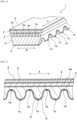
- FIG. 2 is a schematic perspective view illustrating an example of the frictional power transmission belt (raw-edge cogged V-belt) of the present invention.
- FIG. 3 is a schematic cross-sectional view of the frictional power transmission belt of FIG. 2 cut in the longitudinal direction of the belt.
- a frictional power transmission belt 1 has a plurality of cog portions 1a formed on the inner circumferential surface of a belt main body at predetermined intervals along the longitudinal direction (direction A in the drawing) of the belt.
- the cross-sectional shape of the cog portion 1a in the longitudinal direction is substantially semicircular (curved or corrugated), and the cross-sectional shape in the direction orthogonal to the longitudinal direction (width direction or direction B in the drawing) is trapezoidal. That is, each cog portion 1a protrudes in a substantially semicircular shape in the cross section in the A direction from a cog bottom portion 1b in the thickness direction of the belt.
- the frictional power transmission belt 1 has a laminated structure, and a reinforcing fabric 2, a tension rubber layer 3, an adhesion rubber layer 4, a compression rubber layer 5, and a reinforcing fabric 6 are sequentially laminated from the outer peripheral side of the belt toward the inner peripheral side (side where cog portion 1a is formed).
- the cross-sectional shape in the width direction of the belt has the trapezoidal shape in which the belt width decreases from the outer peripheral side to the inner peripheral side of the belt.
- a tension member 4a is buried in the adhesion rubber layer 4, and the cog portion 1a is formed on the compression rubber layer 5 by a mold with a cog.
- the adhesion rubber layer (adhesion layer) is provided in contact with at least a portion of the tension member for the purpose of adhering the tension member and a rubber material for forming the belt.
- the adhesion rubber layer is formed of the vulcanized rubber composition containing a rubber component, short fibers having an average fiber diameter of 2 ⁇ m or more, and a filler.
- the rubber component examples include a known vulcanizable or crosslinkable rubber component and/or elastomer, for example, diene rubbers [natural rubber, isoprene rubber, butadiene rubber, chloroprene rubber, styrene butadiene rubber (SBR), acrylonitrile butadiene rubber (nitrile rubber), hydrogenated nitrile rubber (including a mixed polymer of hydrogenated nitrile rubber and unsaturated carboxylic acid metal salt), etc.], ethylene- ⁇ -olefin elastomers, chlorosulfonated polyethylene rubbers, alkylated chlorosulfonated polyethylene rubbers, epichlorohydrin rubbers, acrylic rubbers, silicone rubbers, urethane rubbers, fluorine rubbers, and the like. These rubber components can be used alone or in combination of two or more kinds thereof.
- diene rubbers natural rubber, isoprene rubber, butadiene rubber, chloroprene rubber, st
- ethylene- ⁇ -olefin elastomers ethylene- ⁇ -olefin rubbers such as ethylene-propylene copolymer (EPM), and ethylene-propylene-diene terpolymer (EPDM, etc.)
- chloroprene rubber is particularly preferable from the viewpoint that a vulcanizing agent and a vulcanization accelerator are easily diffused.
- the chloroprene rubber may be a sulfur-modified type or a non-sulfur-modified type.
- the proportion of chloroprene rubber in the rubber component may be approximately 50% by mass or more (particularly 80% to 100% by mass), and is particularly preferably 100% by mass (chloroprene rubber only).
- short fibers for example, use can be widely made of synthetic fibers such as polyolefin fibers (polyethylene fiber, polypropylene fiber, etc.), polyamide fibers (polyamide 6 fiber, polyamide 66 fiber, polyamide 46 fiber, aramid fiber, etc.), polyalkylene arylate fibers [polyC 2-4 alkyleneC 6-14 arylate fibers such as polyethylene terephthalate (PET) fiber, polyethylene naphthalate (PEN) fiber, etc.], vinylon fibers, polyvinyl alcohol fibers, and polyparaphenylene benzobisoxazole (PBO) fiber; natural fibers such as cotton, hemp, and wool; and inorganic fibers such as a carbon fiber; provided that the short fibers comprise an aramid fiber.
- synthetic fibers such as polyolefin fibers (polyethylene fiber, polypropylene fiber, etc.), polyamide fibers (polyamide 6 fiber, polyamide 66 fiber, polyamide 46 fiber, aramid fiber, etc.
- These short fibers can be used alone or in combination of two or more kinds thereof, provided that the short fibers comprise an aramid fiber.
- An aramid short fiber is advantageous from the viewpoint of being rigid, having high strength and modulus, and of easily protruding on the compression rubber layer surface.
- the aramid short fiber also has high abrasion resistance.
- the aramid fiber is commercially available, for example, under the trade names "Conex”, “Nomex”, “Kevlar”, “Technora”, “Twaron”, and the like.
- the average fiber diameter of the short fibers is 2 ⁇ m or more, for example, 2 to 100 ⁇ m, preferably 3 to 50 ⁇ m (e.g., 5 to 50 ⁇ m), and more preferably approximately 7 to 40 ⁇ m (particularly 10 to 30 ⁇ m). In the case where the average fiber diameter is too small, there is a possibility that a friction coefficient of the surface may not be sufficiently reduced.
- the average length of the short fibers may be, for example, 1 to 20 mm (e.g., 1.2 to 20 mm and preferably 1.5 to 20 mm), preferably 1.3 to 15 mm (e.g., 1.5 to 10 mm), and more preferably approximately 2 to 5 mm (particularly 2.5 to 4 mm).
- the mechanical characteristic e.g., modulus, etc.
- the friction coefficient of the surface may not be sufficiently reduced, and a power transmission efficiency may be decreased.
- the short fibers may be buried in the adhesion rubber layer so as to be oriented in the width direction of the belt.
- the short fibers may be subjected to an adhesion treatment (or surface treatment). It is not necessary that all the short fibers are subjected to an adhesion treatment, and the short fibers subjected to an adhesion treatment and the short fibers not subjected to adhesion treatment (untreated short fibers) may be mixed or used in combination.
- the adhesion treatment of the short fibers can be treated with various adhesion treatments, for example, a treatment liquid containing an initial condensate (prepolymer of novolak or resol type phenolic resin) of phenols and formalin, a treatment liquid containing a rubber component (or latex), a treatment liquid containing the initial condensate and a rubber component (latex), and a treatment liquid containing reactive compound (adhesive compound) such as a silane coupling agent, an epoxy compound (epoxy resin, etc.), and an isocyanate compound.
- an initial condensate prepolymer of novolak or resol type phenolic resin
- a treatment liquid containing a rubber component (or latex) a treatment liquid containing the initial condensate and a rubber component (latex)
- a treatment liquid containing reactive compound (adhesive compound) such as a silane coupling agent, an epoxy compound (epoxy resin, etc.), and an isocyanate
- the short fibers are treated with a treatment liquid containing the initial condensate and a rubber component (latex), particularly at least with a resorcinol-formalin-latex (RFL) liquid.
- a treatment liquid containing the initial condensate and a rubber component (latex) particularly at least with a resorcinol-formalin-latex (RFL) liquid.
- RFL resorcinol-formalin-latex
- the short fibers may be pretreated with a normal adhesive component, for example, a reactive compound (adhesive compound) of an epoxy compound (epoxy resin, etc.) and an isocyanate compound and thereafter, treated with the RFL liquid.
- the RFL liquid is a mixture of an initial condensate of resorcin and formaldehyde and a rubber latex.
- the kind of the latex is not particularly limited, and can be appropriately selected from the above-mentioned rubber components depending on the kind of the rubber component to be bonded.
- the latex may be a diene rubber (natural rubber, isoprene rubber, butadiene rubber, chloroprene rubber, styrene butadiene rubber (SBR), styrene-butadiene-vinylpyridine terpolymer, acrylonitrile butadiene rubber (nitrile rubber), hydrogenated acrylonitrile butadiene rubber (hydrogenated nitrile rubber), etc.), ethylene- ⁇ -olefin elastomer, chlorosulfonated polyethylene rubber, alkylated chlorosulfonated polyethylene rubber, or the like.
- latexes may be used alone or in combination of two or more kinds thereof.
- the preferred latex is a diene rubber (styrene-butadiene-vinylpyridine terpolymer, chloroprene rubber, butadiene rubber, etc.) or a chlorosulfonated polyethylene rubber, and a styrene-butadiene-vinylpyridine terpolymer is preferable for further improving the adhesiveness.
- the short fibers are subjected to an adhesion treatment with the treatment liquid (RFL liquid, etc.) containing at least a styrene-butadiene-vinylpyridine terpolymer
- the adhesiveness between the rubber composition (chloroprene rubber composition, etc.) and the short fibers can be improved.
- the proportion of the initial condensate of resorcin and formalin may be approximately 10 to 100 parts by mass (e.g., 12 to 50 parts by mass and preferably 15 to 30 parts by mass) based on 100 parts by mass of the rubber component of the latex.
- the total solid content concentration of the RFL liquid can be adjusted within a range of 5% to 40% by mass.
- the adhesion rate of the adhesive component (solid content) to the short fibers is, for example, 1% to 25% by mass, preferably 3% to 20% by mass, and more preferably 5% to 15% by mass, and may be approximately 3% to 10% by mass (particularly 4% to 8% by mass).
- the adhesion ratio of the adhesive component is too small, the dispersibility of the short fibers in the rubber composition and the adhesiveness between the short fibers and the rubber composition are insufficient. On the contrary, in the case of too large, there is a possibility that the adhesive component firmly bonds the fiber filaments to each other and the dispersibility is rather decreased.
- the method of preparing the short fibers subjected to an adhesive treatment is not particularly limited, and use can be made of, for example, a method in which long fibers of multifilament are impregnated into an adhesive treatment liquid, dried and then, cut into a predetermined length, a method in which untreated short fibers are immersed in an adhesive treatment liquid for a predetermined period of time, and an excess adhesive treatment liquid is removed by a method such as centrifugal separation, followed by drying, and the like.
- the proportion of the short fibers is, for example, approximately 0.1 to 15 parts by mass (e.g., 0.5 to 12 parts by mass), preferably 1 to 10 parts by mass, and more preferably 2 to 8 parts by mass (particularly 3 to 7 parts by mass), based on 100 parts by mass of the rubber component.
- the proportion of short fibers is too small, there is a possibility that the effect of reducing the friction coefficient of the surface is reduced.
- the adhesive force with the compression rubber layer or the tension rubber layer and the adhesive force with the tension member extremely decreases to cause an interfacial peeling.
- a filler preferably contains silica in viewpoint of increasing the adhesiveness of the adhesion rubber layer and improving the durability of the belt.
- Silica is a fine, bulky white powder formed of silicic acid and/or silicate, and can chemically bond with the rubber component since a plurality of silanol groups are present on the surface thereof.
- Silica includes dry silica, wet silica, surface treated silica, and the like.
- silica can be classified into, for example, a dry type white carbon, a wet type white carbon, a colloidal silica, a precipitated silica, and the like, according to a classification of a preparing method.
- These silicas can be used alone or in combination of two or more kinds thereof.
- the wet type white carbon mainly containing hydrous silicic acid is preferable from the viewpoint of many surface silanol groups and strong chemical bonding force with rubber.
- the average particle diameter of the silica is, for example, approximately 1 to 1,000 nm, preferably 3 to 300 nm, and more preferably approximately 5 to 100 nm (particularly 10 to 50 nm).
- the particle diameter of the silica is too large, there is a possibility that the mechanical properties of the adhesion rubber layer is decreased, and in the case of too small, there is a possibility that it is difficult to disperse uniformly.
- the silica may be either non-porous or porous, but has a nitrogen adsorption specific surface area by the BET method of, for example, approximately 50 to 400 m 2 /g, preferably 70 to 350 m 2 /g, and more preferably 100 to 300 m 2 /g (particularly, 150 to 250 m 2 /g).
- a nitrogen adsorption specific surface area by the BET method of, for example, approximately 50 to 400 m 2 /g, preferably 70 to 350 m 2 /g, and more preferably 100 to 300 m 2 /g (particularly, 150 to 250 m 2 /g).
- the specific surface area is too large, there is a possibility that it is difficult to disperse uniformly, and in the case where the specific surface area is too small, there is a possibility that the mechanical properties of the adhesion rubber layer is decreased.
- the filler may contain carbon black in addition to the silica.
- the average particle diameter of carbon black is, for example, approximately 5 to 200 nm, preferably 10 to 150 nm and more preferably 15 to 100 nm.
- carbon black may have a small particle diameter, for example, approximately 5 to 38 nm, preferably 10 to 35 nm, and more preferably 15 to 30 nm.
- Examples of carbon black having a small particle diameter include SAF, ISAF-HM, ISAF-LM, HAF-LS, HAF, and HAF-HS. These carbon blacks can be used alone or in combination.
- the proportion of carbon black may be 300 parts by mass or less (particularly 200 parts by mass or less) based on 100 parts by mass of silica, and may be, for example, approximately 150 parts by mass or less (e.g., 10 to 150 parts by mass), preferably 100 parts by mass or less (e.g., 15 to 100 parts by mass), more preferably 80 parts by mass or less (e.g., 20 to 80 parts by mass), and particularly 60 parts by mass or less (e.g., 30 to 60 parts by mass).
- the proportion of silica is preferably set larger than the proportion of carbon black.
- the filler may further contain a normal filler.
- a normal filler examples include clay, calcium carbonate, talc, mica, and the like. These fillers can be used alone or in combination of two or more kinds thereof.
- the proportion of silica may be 40% by mass or more, preferably 50% by mass or more, and more preferably 60% by mass or more (particularly 80% by mass or more), based on the whole filler. In the case where the proportion of silica is too small, there is a possibility that the adhesiveness of the adhesion rubber layer is decreased, the adhesive force with the compression rubber layer or the tension rubber layer and the adhesive force with the tension member are extremely decreased, and interfacial peeling occurs.
- the proportion (total proportion) of the filler is, for example, approximately from 30 to 100 parts by mass, preferably 40 to 80 parts by mass, and more preferably 50 to 70 parts by mass (particularly 55 to 65 parts by mass), based on 100 parts by mass of the rubber component.
- the proportion of the filler is too small, there is a possibility that the abrasion resistance decreases due to a decrease in the elastic modulus.
- the elastic modulus is too high and heat generation increases, so that cracks occur in the tension rubber layer and the compression rubber layer at an early stage.
- the rubber composition for forming the adhesion rubber layer may contain a vulcanizing agent or crosslinking agent (or crosslinking agent series), a co-crosslinking agent, a vulcanization aid, a vulcanization accelerator, a vulcanization retardant, metal oxide (e.g., zinc oxide, magnesium oxide, calcium oxide, barium oxide, iron oxide, copper oxide, titanium oxide, aluminum oxide, etc.), a softening agent (oils such as paraffin oil, naphthene oil, etc.), a processing agent or processing aid (a fatty acid such as stearic acid, a fatty acid metal salt such as metal stearate, a fatty acid amide such as stearic acid amide, wax, paraffin, etc.), an adhesion improver [resorcinol-formaldehyde cocondensates, amino resins (a condensate of a nitrogen-containing cyclic compound and formaldehyde, for example, a melamine resin such as
- the metal oxide may act as a crosslinking agent.
- the resorcin-formaldehyde cocondensate and the amino resin may be an initial condensate (prepolymer) of resorcin and/or a nitrogen-containing cyclic compound such as melamine with formaldehyde.
- vulcanizing agent or crosslinking agent normal components can be used depending on the type of the rubber component, and examples thereof include the above-mentioned metal oxides (magnesium oxide, zinc oxide, etc.), organic peroxides (diacyl peroxide, peroxyester, dialkyl peroxide, etc.), a sulfur vulcanizing agent, and the like.
- the sulfur vulcanizing agent include powdered sulfur, precipitated sulfur, colloidal sulfur, insoluble sulfur, highly dispersible sulfur, sulfur chloride (sulfur monochloride, sulfur dichloride, etc.), and the like.
- These crosslinking agents or vulcanizing agents may be used alone or in combination of two or more kinds thereof.
- the metal oxide (magnesium oxide, zinc oxide, etc.) may be used as the vulcanizing agent or crosslinking agent.
- the metal oxide may be used in combination with another vulcanizing agent (sulfur vulcanizing agent, etc.), and the metal oxide and/or the sulfur vulcanizing agent may be used alone or in combination with the vulcanization accelerator.
- the proportion of the vulcanizing agent can be selected from the range of approximately 1 to 20 parts by mass based on 100 parts by mass of the rubber component depending on the kind of the vulcanizing agent and the rubber component.
- the proportion of the organic peroxide as the vulcanizing agent can be selected from the range of approximately 1 to 8 parts by mass, preferably 1.5 to 5 parts by mass, and more preferably 2 to 4.5 parts by mass, based on 100 parts by mass of the rubber component.
- the proportion of the metal oxide can be selected from the range of approximately 1 to 20 parts by mass, preferably 3 to 17 parts by mass, and more preferably 5 to 15 parts by mass (particularly 7 to 13 parts by mass), based on 100 parts by mass of the rubber component.
- co-crosslinking agent crosslinking aid or co-vulcanizing agent co-agent
- crosslinking aids such as multifunctional (iso)cyanurates [e.g., triallyl isocyanurate (TAIC) and triallyl cyanurate TAC), etc.], polydienes (e.g., 1,2-polybutadiene, etc.), metal salts of unsaturated carboxylic acids [e.g., zinc (meth)acrylate, magnesium (meth)acrylate, etc.], oximes (e.g., quinone dioxime, etc.), guanidines (e.g., diphenylguanidine, etc.), polyfunctional (meth)acrylates [e.g., ethylene glycol di(meth)acrylate, butanediol di(meth)acrylate, trimethylolpropane tri(meth)acrylate, etc.], bismaleimides (aliphatic bismaleimide such as N, N'-1,2-ethylene
- crosslinking aids can be used alone or in combination of two or more kinds thereof.
- crosslinking aids bismaleimides (arene bismaleimide such as N,N'-m-phenylenedimaleimide or aromatic bismaleimide) are preferred.
- arene bismaleimide such as N,N'-m-phenylenedimaleimide or aromatic bismaleimide
- the addition of a bismaleimide can increase the degree of crosslinking and prevent adhesion abrasion and the like.
- the proportion of the co-crosslinking agent can be selected from the range of approximately 0.01 to 10 parts by mass based on 100 parts by mass of the rubber component, in terms of solid content, and for example, may be approximately 0.1 to 5 parts by mass (e.g., 0 3 to 4 parts by mass), and preferably 0.5 to 3 parts by mass (e.g., 0.5 to 2 parts by mass).
- vulcanization accelerator examples include thiuram accelerators [e.g., tetramethylthiuram monosulfide (TMTM), tetramethylthiuram disulfide (TMTD), tetraethylthiuram disulfide (TETD), tetrabutylthiuram disulfide (TBTD), dipentamethylenethiuram tetrasulfide (DPTT), N,N'-dimethyl-N,N'-diphenylthiuram disulfide, etc.], thiazole accelerators [e.g., 2-mercaptobenzothiazole, a zinc salt of 2-mercaptobenzothiazole, 2-mercaptothiazoline, dibenzothiazyl disulfide, 2-(4'-morpholinodithio)benzothiazole, etc.), etc.], sulfenamide accelerators [e.g., N-cyclohexyl-2-benzothiazyl sulf
- the proportion of the vulcanization accelerator may be, for example, approximately 0.1 to 15 parts by mass, preferably 0.3 to 10 parts by mass, and more preferably 0.5 to 5 parts by mass, based on 100 parts by mass of the rubber component, in terms of solid content.
- the proportion of the softening agent may be, for example, approximately 1 to 30 parts by mass, and preferably 3 to 20 parts by mass (e.g., 5 to 10 parts by mass), based on 100 parts by mass of the total amount of the rubber component.
- the proportion of the processing agent or processing aid may be approximately 10 parts by mass or less (e.g., 0 to 10 parts by mass), preferably 0.1 to 5 parts by mass, and more preferably 0.3 to 3 parts by mass (particularly 0.5 to 2 parts by mass), based on 100 parts by mass of the rubber component.
- the proportion of the adhesion improver may be approximately 0.1 to 20 parts by mass, preferably 0.3 to 10 parts by mass, and more preferably 0.5 to 5 parts by mass (1 to 3 parts by mass), based on 100 parts by mass of the rubber component.
- the proportion of the antioxidant may be, for example, approximately 0.5 to 15 parts by mass, preferably 1 to 10 parts by mass, and more preferably 2.5 to 7.5 parts by mass (particularly 3 to 7 parts by mass), based on 100 parts by mass of the total amount of the rubber component.
- the mechanical characteristic of the adhesion rubber layer can be appropriately selected according to the required performance.
- the rubber hardness is, for example, approximately 75° to 90°, preferably 80° to 88°, and more preferably 82° to 86°.
- the adhesion rubber layer having a high rubber hardness may be formed. For example, by blending a large amount of the filler, the rubber hardness may be adjusted to approximately 84° to 90°.
- the adhesion rubber layer may be formed of a vulcanized rubber composition having a ratio (compression stress/bending stress ratio) of compression stress to bending stress being 0.5 or more.
- the compression stress/bending stress ratio is, for example, approximately 0.5 to 0.9, preferably 0.55 to 0.85, and more preferably 0.6 to 0.8 (particularly 0.65 to 0.8). In the case where the compression stress/bending stress ratio is too small, there is a possibility that the power transmission efficiency and durability of the belt decrease.
- the thickness of the adhesion rubber layer can be appropriately selected according to the type of the belt, and may be, for example, approximately 0.4 to 3.0 mm, preferably 0.6 to 2.2 mm, and more preferably 0.8 to 1.4 mm.
- the tension member is not particularly limited, generally, cords (twisted cords) disposed at predetermined intervals in the width direction of the belt can be used.
- the cords are disposed to extend in the longitudinal direction of the belt and are normally disposed to extend in parallel at a predetermined pitch parallel to the longitudinal direction of the belt.
- the cord only has to be in contact with the adhesion rubber layer at a part thereof, and any of a form in which the adhesion rubber layer buries the cord, a form in which the cord is buried between the adhesion rubber layer and the tension rubber layer, and a form in which the cord is buried between the adhesion rubber layer and the compression rubber layer may be employed.
- the form in which the adhesion rubber layer buries the cord is preferred.
- polyester fibers polyalkylene arylate fibers
- C 2-4 alkylene arylate such as ethylene terephthalate and ethylene-2,6-naphthalate
- synthetic fibers such as an aramid fiber, inorganic fibers such as a carbon fiber, and the like
- polyester fibers polyethylene terephthalate fibers and polyethylene naphthalate fibers
- the fibers may be multifilament yarns.
- the fineness of the multifilament yarns may be, for example, approximately 2,000 to 10,000 denier (particularly 4,000 to 8,000 denier).
- the multifilament yarns may contain, for example, approximately 100 to 5,000, preferably 500 to 4,000, and more preferably 1,000 to 3,000 monofilament yarns.
- the cord normally, twisted cords (e.g., plied twists, single twists, Lang's twists, etc.) using multifilament yarns can be used.
- the average core diameter of the cord may be, for example, approximately 0.5 to 3 mm, preferably 0.6 to 2 mm, and more preferably 0.7 to 1.5 mm.
- the cord may be subjected to an adhesion treatment (or surface treatment) in the same manner as in the short fibers in order to improve the adhesiveness to the rubber component.
- the cord is preferably subjected to the adhesion treatment with at least RFL liquid.
- the vulcanizable rubber composition for forming the compression rubber layer (inner rubber layer or inner layer) and the tension rubber layer (outer rubber layer or outer layer) may contain a rubber component (chloroprene rubber, etc.), a vulcanizing agent or crosslinking agent (metal oxides such as magnesium oxide and zinc oxide and sulfur vulcanizing agents such as sulfur, etc.), a co-crosslinking agent or crosslinking aid (maleimide crosslinking agents such as N,N'-m-phenylenedimaleimide, etc.), a vulcanization accelerator (TMTD, DPTT, CBS, etc.), a filler (carbon black, silica, etc.), a softening agent (oils such as naphthene oil, etc.), a processing agent or processing aid (stearic acid, metal stearate, wax, paraffin, etc.), an antioxidant, an adhesion improver, a filler (clay,
- a rubber component chloroprene rubber, etc.
- the vulcanizable rubber composition for forming the compression rubber layer and the tension rubber layer may contain short fibers.
- the short fibers include the same fibers as the short fibers mixed in the adhesion rubber layer.
- the synthetic fibers or natural fibers, particularly the synthetic fibers (polyamide fibers, polyalkylene arylate fibers, etc.), and more particularly the short fibers containing at least the aramid fiber are preferable from the viewpoint of being rigid and having high strength and modulus.
- the average fiber diameter and average length of the short fibers can be selected from the same range as in the short fibers of the adhesion rubber layer, and an adhesion treatment (or surface treatment) may be performed in the same manner as in the adhesion rubber layer.
- the short fibers may be made protrude from the surface by grinding the surface (frictional power transmission surface).
- the average protruding height of the short fibers may be approximately 50 ⁇ m or more (e.g., 50 to 200 ⁇ m).
- rubber of the same type (diene rubbers, etc.) or the same kind (chloroprene rubber, etc.) as the rubber component of the rubber composition of the adhesion rubber layer is used in many cases.
- the proportions of the vulcanizing agent or crosslinking agent, the co-crosslinking agent or crosslinking aid, the vulcanization accelerator, the softening agent, the processing agent or processing aid, and the antioxidant can be selected from the same range as those of the rubber composition of the adhesion rubber layer, respectively.
- the proportion of short fibers can be selected from the range of approximately 5 to 50 parts by mass based on 100 parts by mass of the rubber component, and normally, may be approximately 10 to 40 parts by mass, preferably 15 to 35 parts by mass, and more preferably 20 to 30 parts by mass.
- the proportion of the filler is approximately 1 to 100 parts by mass, preferably 3 to 50 parts by mass, and more preferably 5 to 40 parts by mass, based on 100 parts by mass of the rubber component.
- the average thickness of the compression rubber layer can be appropriately selected according to the type of the belt, and is, for example, approximately 2 to 25 mm, preferably 3 to 16 mm, and more preferably 4 to 12 mm.
- the thickness of the tension rubber layer can be appropriately selected according to the type of the belt, and is, for example, approximately 0.8 to 10.0 mm, preferably 1.2 to 6.5 mm, and more preferably 1.6 to 5.2 mm.
- a reinforcing fabric in the frictional power transmission belt, it is not limited to a form of laminating the reinforcing fabric on the surface of the compression rubber layer.
- a reinforcing fabric may be laminated on the surface of the tension rubber layer (surface opposite to the adhesion rubber layer), or a reinforcing layer may be buried in the compression rubber layer and/or the tension rubber layer (e.g., a form described in JP-A-2010-230146 , etc.).
- the reinforcing fabric can be formed of, for example, a fabric material (preferably a woven fabric) such as a woven fabric, a wide angle canvas, a knitted fabric, an unwoven fabric.
- the reinforcing fabric may be laminated on the surface of the compression rubber layer and/or the tension rubber layer after the above-described adhesion treatment, for example, a treatment (immersion treatment, etc.) with an RFL liquid, a friction for rubbing an adhesive rubber into the fabric material, or laminating (coating) the adhesive rubber and the fabric material.
- a treatment immersion treatment, etc.
- RFL liquid a friction for rubbing an adhesive rubber into the fabric material
- laminating (coating) the adhesive rubber and the fabric material for example, a treatment (immersion treatment, etc.) with an RFL liquid, a friction for rubbing an adhesive rubber into the fabric material, or laminating (coating) the adhesive rubber and the fabric material.
- a method for manufacturing the frictional power transmission belt of the present invention is not particularly limited, and a conventional method can be used for a laminating step (method of manufacturing a belt sleeve) of each layer.
- a laminated body including a reinforcing fabric (lower fabric) and a compression rubber layer sheet (unvulcanized rubber) may be installed on a flat cogged mold in which tooth portions and groove portions are alternately disposed, with the reinforcing fabric downward, and pressed at a temperature of approximately 60°C to 100°C (particularly 70°C to 80°C) to prepare a cog pad having a cog portion molded (pad which is not completely vulcanized and is in a semi-vulcanized state), and thereafter, both ends of the cog pad may be cut perpendicularly from a top portion of a cog ridge portion.
- a cylindrical mold may be covered with an inner mother die in which tooth portions and groove portions are alternately disposed, the cog pad may be wound to engage with the tooth portions and the groove portions and jointed at the top portion of the cog ridge portion, and a first adhesion rubber layer sheet (lower adhesive rubber: unvulcanized rubber) may be laminated on the wound cog pad.
- a cord serving as a tension member may be spun into spiral shape, and a second adhesion rubber layer sheet (upper adhesive rubber: the same as the first adhesion rubber layer sheet), a tension rubber layer sheet (unvulcanized rubber), and a reinforcing fabric (upper fabric) may be sequentially wound thereon to prepare a molded body.
- the mold may be covered by a jacket, installed in a vulcanizing can, and vulcanized at a temperature of approximately 120°C to 200°C (particularly 150°C to 180°C) to prepare a belt sleeve, and then, the belt sleeve may be cut into a V-shape by using a cutter or the like.
- the power transmission efficiency is an index that the belt transmits a rotational torque from a drive pulley to a driven pulley, and means that the higher the power transmission efficiency, the smaller the power transmission loss of the belt and the better fuel saving performance.
- a power transmission efficiency can be obtained as follows.
- T 1 of the drive pulley can be represented as ⁇ 1 ⁇ T e ⁇ r 1 .
- T e is an effective tension obtained by subtracting a tension on a slack side (tension on a side where the belt runs toward the driven pulley) from a tension on a tight side (tension on a side where the belt runs toward the drive pulley).
- a rotational torque T 2 of the driven pulley is represented as ⁇ 2 ⁇ T e ⁇ r 2 .
- the power transmission efficiency T 2 /T 1 is calculated by dividing the rotational torque T 2 of the driven pulley by the rotational torque T 1 of the drive pulley and can be represented by a following equation.
- the value of the power transmission efficiency is 1 when there is no power transmission loss, and when there is some power transmission loss, the value decreases by that loss. That is, it means that the closer to 1, the smaller the power transmission loss of the belt and the better fuel saving performance.
- An adhesion rubber layer sheet was press vulcanized at a temperature of 160°C for 30 minutes to prepare a vulcanized rubber sheet (100 mm ⁇ 100 mm ⁇ 2 mm thickness).
- the hardness was measured by using a laminate obtained by laminating three sheets of vulcanized rubber sheets as a sample and the hardness was measured by using a durometer type A hardness tester.
- a vulcanized rubber sheet (50 mm ⁇ 50 mm ⁇ 8 mm thickness) prepared by press vulcanizing an adhesion rubber layer sheet at a temperature of 160°C for 30 minutes, was cut out with a hollow drill having an inner diameter of 16.2 ⁇ 0.05 mm to prepare a cylindrical sample having a diameter of 16.2 ⁇ 0.2 mm and a thickness of 6 to 8 mm.
- the abrasion loss of the vulcanized rubber was measured by using a rotating cylindrical drum device (DIN abrasion tester) around which an abrasive cloth was wound.
- An adhesion rubber layer sheet was press vulcanized at a temperature of 160°C for 30 minutes to prepare a vulcanized rubber molded body (length 25 mm, width 25 mm, thickness 12.5 mm).
- the short fibers were made to orient in a direction perpendicular to a compression surface (thickness direction).
- the vulcanized rubber molded body was interposed vertically between two metal compression plates (in an interposed state where the vulcanized molded body was not pressed by the compression plate, the position of the upper compression plate was taken as the initial position) and the upper compression plate was pressed against the vulcanized rubber molded body (pressure surface 25 mm ⁇ 25 mm) at a rate of 10 mm/min to distort the vulcanized rubber molded body by 20%. After holding for 1 second in this state, the compression plate was returned upward to the initial position (preliminary compression).
- An adhesion rubber layer sheet was press vulcanized at a temperature of 160°C for 30 minutes to prepare a vulcanized rubber molded body (60 mm ⁇ 25 mm ⁇ 6.5 mm thickness).
- the short fibers were made to orient in a direction parallel to the width (short side direction) of the vulcanized rubber molded body.
- this vulcanized rubber molded body 21 was placed on a pair of rotatable rolls 22a and 22b (diameter of 6 mm) at intervals of 20 mm and supported, and a metal pressing member 23 was placed in the width direction (orientation direction of short fibers) at the center of the upper surface of the vulcanized rubber molded body.
- the tip end portion of the pressing member 23 has a semicircular shape with a diameter of 10 mm, and by the tip end portion thereof, the vulcanized rubber molded body 21 can be pressed smoothly.
- a frictional force acts between the lower surface of the vulcanized rubber molded body 21 and the rolls 22a and 22b as the vulcanized rubber molded body 21 is compressed and deformed, by making the rolls 22a and 22b rotatable, the influence due to friction is reduced.
- a state where the tip end portion of the pressing member 23 contacted the upper surface of the vulcanized rubber molded body 21 and was not pressed was taken as an initial position, and the upper surface of the vulcanized rubber molded body 21 was pressed downward at the speed of 100 mm/min by the pressing member 23 from this state, and a stress when a bending strain reached 8% was measured as a bending stress.
- the ratio (compression/bending ratio) of the measured compression stress to the measured bending stress was calculated.
- the compression stress and bending stress can be used as indices that influence the power transmission efficiency and durability, and the larger the compression stress is and the smaller the bending stress is, the more the power transmission efficiency and durability tend to be improved. That is, a large compression/bending ratio works in a direction where the power transmission efficiency and durability are improved, and conversely a small compression/bending ratio works in a direction where the power transmission efficiency and durability are decreased.
- a plurality of cords were disposed in parallel so that the width was 25 mm on one side of an unvulcanized adhesion rubber layer sheet having a thickness of 4 mm, and canvas was laminated on the other side, and this laminated body (cord, adhesion rubber layer sheet, and canvas) was subjected to press vulcanization (temperature of 160°C, time of 30 min, pressure of 2.0 MPa) to prepare a strip sample (25 mm ⁇ 150 mm ⁇ 4 mm thickness) for a peeling test.
- press vulcanization temperature of 160°C, time of 30 min, pressure of 2.0 MPa
- the peeling test was performed at a tensile rate of 50 mm/min, and the peeling force (vulcanizing adhesive force) between the cord and the adhesion rubber layer sheet was measured under a room temperature atmosphere (23°C).
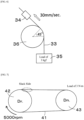
- one end of the cut belt 33 was fixed to a load cell 34, a load 35 of 3 kgf was placed on the other end thereof, and the belt 33 was wound around the pulley 36 so that the winding angle of the belt to the pulley 36 was set to be 45°.
- the belt 33 on the load cell 34 side was pulled at a speed of 30 mm/sec for approximately 15 seconds, and the average friction coefficient of the frictional power transmission surface was measured.
- the pulley 36 was fixed so as not to rotate.
- a high-speed running test was performed by using a biaxial running tester including a drive (Dr.) pulley 42 having a diameter of 95 mm and a driven (Dn.) pulley 43 having a diameter of 85 mm.
- a raw-edge cogged V-belt 41 was hung on each of the pulleys 42 and 43, a load of 3 N ⁇ m was applied to the driven pulley 43, and the belt 41 was run under a room temperature atmosphere (23°C) at a rotation speed of 5,000 rpm of the drive pulley 42.
- the surface temperature of the belt reached a maximum of 60°C during running.
- the rotation speed of the driven pulley 43 was read from a detector, and the power transmission efficiency was obtained from the above-mentioned calculation formula.
- the power transmission efficiency for each Example and Comparative Example was represented in relative value converted by taking the power transmission efficiency of Comparative Example 1 as "1". In the case where the value is larger than 1, it is judged that the power transmission efficiency, that is, fuel saving performance of the belt 41 is high.
- a durability running test was performed by using a biaxial running tester including a drive (Dr.) pulley 52 having a diameter of 50 mm and a driven (Dn.) Pulley 53 having a diameter of 125 mm.
- the raw-edge cogged V-belt 51 was hung on each of the pulleys 52 and 53, a load of 10 N ⁇ m was applied to the driven pulley 53, and the belt 51 was run at an atmospheric temperature of 80°C for a maximum of 60 hours at a rotation speed of 5,000 rpm of the drive pulley 52.
- the belt 51 ran for 60 hours, it was judged that there was no problem in durability.
- the side surface of the belt (surface in contact with the pulley) after running was observed with a microscope, and the presence or absence of peeling between the rubber layers and peeling of the cord was investigated.
- the peeling depth was measured with a microscope.
- a weight of the belt before running and a weight of the belt after running were measured with an electronic balance and the weight difference was calculated as the abrasion amount of the belt in durability running.
- each of the rubber compositions of Table 1 (adhesion rubber layer) and Table 2 (compression rubber layer and tension rubber layer) was subjected to rubber kneading by using a known method such as a Banbury mixer and the kneaded rubber was passed through a calender roll to prepare a rolled rubber sheet (adhesion rubber layer sheet, compression rubber layer sheet, and tension rubber layer sheet).
- Table 2 Compression rubber layer and tension rubber layer
- Composition parts
- Chloroprene rubber 100
- Aramid short fiber 20
- Naphthene oil 5
- Magnesium oxide Carbon black
- Antioxidant 4
- Zinc oxide 5
- N,N'-m-phenylenedimaleimide 4
- Stearic acid 2
- Vulcanization accelerator TMTD 1 Sulfur 0.5
- a laminated body of a reinforcing fabric and a compression rubber layer sheet (unvulcanized rubber) was installed on a flat cogged mold in which tooth portions and groove portions were alternately disposed, with the reinforcing fabric downward, and pressed at 75°C to prepare a cog pad having a cog portion molded (which was not completely vulcanized, and was in a semi-vulcanized state). Thereafter, both ends of the cog pad were cut perpendicularly from a top portion of a cog ridge portion.
- a cylindrical mold was covered with an inner mother die in which tooth portions and groove portions were alternately disposed, the cog pad was wound to engage with the tooth portions and the groove portions and jointed at the top portion of the cog ridge portion.
- An adhesion rubber layer sheet (lower adhesive rubber: unvulcanized rubber) was laminated on the wound cog pad. Thereafter, a cord was spun into spiral shape, and another adhesion rubber layer sheet (upper adhesive rubber: the same as the above adhesion rubber layer sheet), a tension rubber layer sheet (unvulcanized rubber), and an upper fabric were sequentially wound thereon to prepare a molded body.
- the belt sleeve was cut into a V-shaped cross section with a predetermined width in the longitudinal direction of the belt with a cutter and finished to a raw-edge cogged V-belt (size: upper width of 22.0 mm, thickness of 11.0 mm, and outer peripheral length of 800 mm) which was a belt having the structure illustrated in FIG. 2 , that is, a variable speed belt having a cog on the inner peripheral side of the belt.
- Example 6 contained 60 parts by mass of the total amount of filler and contained the aramid short fibers, since the proportion of carbon black was larger than that of silica, there was no problem in friction coefficient, but adhesiveness was slightly insufficient, the interfacial peeling from the cord and the interlayer peeling from the compression rubber layer (or tension rubber layer) was likely to occur as compared with Examples 2 to 4, and the durability slightly decreased.
- Example 1 Although the adhesion rubber layer of Example 1 contained 60 parts by mass of the total amount of the filler and contained the aramid short fibers, since the amount of the aramid short fibers was small (0.5 parts by mass), the reduction of the friction coefficient was slightly insufficient and the durability was good, but improvement in the power transmission efficiency was not observed as much as in Examples 2 to 4.
- Example 5 Although the adhesion rubber layer of Example 5 contained 60 parts by mass of the total amount of filler and contained the aramid short fibers, since the amount of aramid short fibers was large (11 parts by mass), the friction coefficient was significantly reduced and the power transmission efficiency was good, the adhesiveness (peeling force) was slightly insufficient, and the interfacial peeling from the cord and the interlayer peeling from the compression rubber layer (or tension rubber layer) was likely to occur as compared with Examples 2 to 4, and the durability decreased.
- Examples 10 to 14 were examples in which the total amount of the filler (silica and carbon black) was changed to a value other than 60 parts by mass.
- Example 11 having 40 parts by mass of the total amount of filler had a slightly low mechanical characteristic and lacked lateral pressure resistance, so that it was likely to deform (buckle) in a durability running, slight peeling occurred between layers with the compression rubber layer (or tension rubber layer), and the durability was decreased as compared with Examples 2 to 4.
- Example 14 having 80 parts by mass of the total amount of the filler, whereas it was rigid and hard to deform (buckle), it was hard to bend, and stress was concentrated on the interface, so that interfacial peeling from the cord and interlayer peeling from the compression rubber layer (or tension surface rubber layer) was likely to occur and the durability decreased, as compared with Examples 2 to 4.
- Example 10, 12 and 13 the same performance as Examples 2 to 4 was obtained.
- Comparative Examples 1 to 4 were an adhesion rubber layer in which the total amount of filler (silica and carbon black) was 60 parts by mass. Since the adhesion rubber layer of Comparative Example 1 did not contain the short fibers, the friction coefficient was high and the durability was good, but the power transmission efficiency was low.
- Comparative Example 2 is an example in which the adhesion rubber layer did not contain the short fibers and the filler was only carbon black (did not contain silica). Due to the high proportion of carbon black, the bending stress was large and the bending fatigue resistance was lacked, and since there was no silica, the adhesiveness (peeling force) was lacked, the friction coefficient was high, and slidability was lacked. Due to these influences, in durability running, the interfacial peeling from the cord and the interlayer peeling from the compression rubber layer (or tension rubber layer) significantly occurred and the durability was low.
- Comparative Example 3 is an example in which the adhesion rubber layer did not contain the short fibers, and the filler was only silica (did not contain carbon black). Since silica with high adhesiveness was contained, peeling force (adhesion) was high and the interfacial peeling from the cord or the interlayer peeling from the compression rubber layer (or tension rubber layer) did not occur, but the abrasion amount of the belt was large and the abrasion resistance was low. In addition, the friction coefficient was high and the power transmission efficiency was low.
- the frictional power transmission belt of the present invention can be used in a transmission (continuously variable transmission device) in which the gear ratio varies steplessly while the belt is running, for example, a raw-edge cogged V-belt or a raw-edge double cogged V-belt used for a continuously variable transmission device of a motorcycle, an ATV (4 wheel buggy), a snowmobile, and the like.
Landscapes
- Chemical & Material Sciences (AREA)
- Engineering & Computer Science (AREA)
- General Engineering & Computer Science (AREA)
- Medicinal Chemistry (AREA)
- Polymers & Plastics (AREA)
- Organic Chemistry (AREA)
- Health & Medical Sciences (AREA)
- Chemical Kinetics & Catalysis (AREA)
- Mechanical Engineering (AREA)
- Textile Engineering (AREA)
- Compositions Of Macromolecular Compounds (AREA)
- Transmissions By Endless Flexible Members (AREA)
- Laminated Bodies (AREA)
Claims (11)
- Reibungskraftübertragungsriemen, umfassend: ein Spannelement, das sich in einer Längsrichtung eines Riemens erstreckt, und eine Adhäsionskautschukschicht, die mit mindestens einem Teil des Spannelements in Kontakt steht,
worin die Adhäsionskautschukschicht aus einer vulkanisierten Kautschukzusammensetzung gebildet ist, umfassend:eine Kautschukkomponente,kurze Fasern mit einem durchschnittlichen Faserdurchmesser von 2 µm oder mehr undeinen Füllstoff,worin die kurzen Fasern eine Aramidfaser umfassen undworin der Reibungskraftübertragungsriemen ein Keilriemen mit grober Verzahnung ist. - Reibungskraftübertragungsriemen gemäß Anspruch 1,
worin die Kautschukkomponente Chloroprenkautschuk umfasst. - Reibungskraftübertragungsriemen gemäß Anspruch 1 oder 2,
worin der durchschnittliche Faserdurchmesser der kurzen Fasern 5 bis 50 µm beträgt. - Reibungskraftübertragungsriemen gemäß einem der Ansprüche 1 bis 3,
worin die kurzen Fasern eine durchschnittliche Faserlänge von 1,5 bis 20 mm aufweisen. - Reibungskraftübertragungsriemen gemäß einem der Ansprüche 1 bis 4,
worin ein Anteil der kurzen Fasern, basierend auf 100 Massenteile der Kautschukkomponente, 0,1 bis 15 Massenteile beträgt. - Reibungskraftübertragungsriemen gemäß einem der Ansprüche 1 bis 5,
worin der Füllstoff Siliciumdioxid umfasst. - Reibungskraftübertragungsriemen gemäß Anspruch 6,
worin der Füllstoff ferner Ruß umfasst. - Reibungskraftübertragungsriemen gemäß Anspruch 7,
worin ein Anteil des Rußes, basierend auf 100 Massenteile Siliciumdioxid, 10 bis 150 Massenteile beträgt. - Reibungskraftübertragungsriemen gemäß einem der Ansprüche 1 bis 8,
worin ein Anteil des Füllstoffs, basierend auf 100 Massenteile der Kautschukkomponente, 30 bis 100 Massenteile beträgt. - Reibungskraftübertragungsriemen gemäß einem der Ansprüche 1 bis 9,
worin die Adhäsionskautschukschicht aus der vulkanisierten Kautschukzusammensetzung gebildet ist, die ein Verhältnis (Druckspannungs-/Biegespannungsverhältnis) von Druckspannung zu Biegespannung von 0,6 bis 0,8 aufweist. - Reibungskraftübertragungsriemen gemäß einem der Ansprüche 1 bis 10, der ein Riemen mit variabler Geschwindigkeit ist, der in einer stufenlos verstellbaren Getriebevorrichtung verwendet wird.
Applications Claiming Priority (3)
| Application Number | Priority Date | Filing Date | Title |
|---|---|---|---|
| JP2015249033 | 2015-12-21 | ||
| JP2016240727A JP6650388B2 (ja) | 2015-12-21 | 2016-12-12 | 摩擦伝動ベルト |
| PCT/JP2016/087895 WO2017110784A1 (ja) | 2015-12-21 | 2016-12-20 | 摩擦伝動ベルト |
Publications (3)
| Publication Number | Publication Date |
|---|---|
| EP3396201A1 EP3396201A1 (de) | 2018-10-31 |
| EP3396201A4 EP3396201A4 (de) | 2019-09-11 |
| EP3396201B1 true EP3396201B1 (de) | 2024-09-04 |
Family
ID=59234140
Family Applications (1)
| Application Number | Title | Priority Date | Filing Date |
|---|---|---|---|
| EP16878673.9A Active EP3396201B1 (de) | 2015-12-21 | 2016-12-20 | Friktionsantriebsriemen |
Country Status (2)
| Country | Link |
|---|---|
| EP (1) | EP3396201B1 (de) |
| JP (1) | JP6650388B2 (de) |
Families Citing this family (3)
| Publication number | Priority date | Publication date | Assignee | Title |
|---|---|---|---|---|
| JP7368082B2 (ja) * | 2017-11-24 | 2023-10-24 | 三ツ星ベルト株式会社 | 伝動用vベルト |
| US12528895B2 (en) | 2020-01-28 | 2026-01-20 | Compagnie Generale Des Etablissements Michelin | Rubber composition |
| CN113531046B (zh) * | 2021-07-02 | 2023-04-07 | 浙江保尔力橡塑股份有限公司 | 一种新型切边联组v带及其制备工艺 |
Family Cites Families (4)
| Publication number | Priority date | Publication date | Assignee | Title |
|---|---|---|---|---|
| JPH0729330Y2 (ja) * | 1990-08-10 | 1995-07-05 | 三ツ星ベルト株式会社 | 動力伝動用vベルト |
| JP5243834B2 (ja) * | 2008-04-08 | 2013-07-24 | 三ツ星ベルト株式会社 | 動力伝動用ベルト |
| DE112009005196T5 (de) * | 2009-09-01 | 2012-06-28 | Bando Chemical Industries, Ltd. | Flachriemen |
| JP5945562B2 (ja) * | 2013-03-28 | 2016-07-05 | 三ツ星ベルト株式会社 | 伝動用ベルト及びベルト変速装置 |
-
2016
- 2016-12-12 JP JP2016240727A patent/JP6650388B2/ja active Active
- 2016-12-20 EP EP16878673.9A patent/EP3396201B1/de active Active
Also Published As
| Publication number | Publication date |
|---|---|
| EP3396201A1 (de) | 2018-10-31 |
| JP2017116100A (ja) | 2017-06-29 |
| JP6650388B2 (ja) | 2020-02-19 |
| EP3396201A4 (de) | 2019-09-11 |
Similar Documents
| Publication | Publication Date | Title |
|---|---|---|
| EP2980445B1 (de) | Transmissionsriemen | |
| US11300178B2 (en) | Friction drive belt | |
| EP3587859B1 (de) | Transmissionsriemen | |
| CN109073040B (zh) | 摩擦传动带 | |
| CA2902421C (en) | Power transmission belt and belt-type continuously variable transmission | |
| WO2012161141A1 (ja) | 伝動用ベルト | |
| CN109477548B (zh) | 传动用v带 | |
| EP3396202B1 (de) | Reibungsübertragungsriemen und verfahren zur herstellung davon | |
| EP3444501B1 (de) | Reibungsübertragungsband | |
| JP6747924B2 (ja) | 摩擦伝動ベルト及びその製造方法 | |
| EP3396201B1 (de) | Friktionsantriebsriemen | |
| TWI842352B (zh) | 傳動帶用橡膠組合物及傳動帶 | |
| EP3489544B1 (de) | Transmissionskeilriemen | |
| EP3444500B1 (de) | Reibungsübertragungsband | |
| EP4296537A1 (de) | Transmissionskeilriemen | |
| WO2017179690A1 (ja) | 摩擦伝動ベルト | |
| JP7787121B2 (ja) | 伝動ベルト用ゴム組成物および伝動ベルト | |
| EP4549778A1 (de) | Kautschukzusammensetzung für treibriemen, treibriemen und verfahren zur herstellung eines treibriemens |
Legal Events
| Date | Code | Title | Description |
|---|---|---|---|
| STAA | Information on the status of an ep patent application or granted ep patent |
Free format text: STATUS: THE INTERNATIONAL PUBLICATION HAS BEEN MADE |
|
| PUAI | Public reference made under article 153(3) epc to a published international application that has entered the european phase |
Free format text: ORIGINAL CODE: 0009012 |
|
| STAA | Information on the status of an ep patent application or granted ep patent |
Free format text: STATUS: REQUEST FOR EXAMINATION WAS MADE |
|
| 17P | Request for examination filed |
Effective date: 20180619 |
|
| AK | Designated contracting states |
Kind code of ref document: A1 Designated state(s): AL AT BE BG CH CY CZ DE DK EE ES FI FR GB GR HR HU IE IS IT LI LT LU LV MC MK MT NL NO PL PT RO RS SE SI SK SM TR |
|
| AX | Request for extension of the european patent |
Extension state: BA ME |
|
| DAV | Request for validation of the european patent (deleted) | ||
| DAX | Request for extension of the european patent (deleted) | ||
| RIC1 | Information provided on ipc code assigned before grant |
Ipc: C08L 77/00 20060101ALI20190801BHEP Ipc: C08L 21/00 20060101ALI20190801BHEP Ipc: C08K 3/36 20060101ALI20190801BHEP Ipc: F16G 5/20 20060101ALI20190801BHEP Ipc: F16G 1/08 20060101AFI20190801BHEP Ipc: F16G 5/06 20060101ALI20190801BHEP Ipc: C08K 3/04 20060101ALI20190801BHEP Ipc: C08K 7/02 20060101ALI20190801BHEP Ipc: C08L 11/00 20060101ALI20190801BHEP |
|
| A4 | Supplementary search report drawn up and despatched |
Effective date: 20190809 |
|
| TPAC | Observations filed by third parties |
Free format text: ORIGINAL CODE: EPIDOSNTIPA |
|
| STAA | Information on the status of an ep patent application or granted ep patent |
Free format text: STATUS: EXAMINATION IS IN PROGRESS |
|
| 17Q | First examination report despatched |
Effective date: 20230919 |
|
| GRAP | Despatch of communication of intention to grant a patent |
Free format text: ORIGINAL CODE: EPIDOSNIGR1 |
|
| STAA | Information on the status of an ep patent application or granted ep patent |
Free format text: STATUS: GRANT OF PATENT IS INTENDED |
|
| INTG | Intention to grant announced |
Effective date: 20240418 |
|
| GRAS | Grant fee paid |
Free format text: ORIGINAL CODE: EPIDOSNIGR3 |
|
| GRAA | (expected) grant |
Free format text: ORIGINAL CODE: 0009210 |
|
| STAA | Information on the status of an ep patent application or granted ep patent |
Free format text: STATUS: THE PATENT HAS BEEN GRANTED |
|
| AK | Designated contracting states |
Kind code of ref document: B1 Designated state(s): AL AT BE BG CH CY CZ DE DK EE ES FI FR GB GR HR HU IE IS IT LI LT LU LV MC MK MT NL NO PL PT RO RS SE SI SK SM TR |
|
| REG | Reference to a national code |
Ref country code: GB Ref legal event code: FG4D |
|
| P01 | Opt-out of the competence of the unified patent court (upc) registered |
Free format text: CASE NUMBER: APP_44858/2024 Effective date: 20240801 |
|
| REG | Reference to a national code |
Ref country code: CH Ref legal event code: EP |
|
| REG | Reference to a national code |
Ref country code: IE Ref legal event code: FG4D |
|
| REG | Reference to a national code |
Ref country code: DE Ref legal event code: R096 Ref document number: 602016089297 Country of ref document: DE |
|
| REG | Reference to a national code |
Ref country code: LT Ref legal event code: MG9D |
|
| REG | Reference to a national code |
Ref country code: NL Ref legal event code: MP Effective date: 20240904 |
|
| PG25 | Lapsed in a contracting state [announced via postgrant information from national office to epo] |
Ref country code: NO Free format text: LAPSE BECAUSE OF FAILURE TO SUBMIT A TRANSLATION OF THE DESCRIPTION OR TO PAY THE FEE WITHIN THE PRESCRIBED TIME-LIMIT Effective date: 20241204 |
|
| PG25 | Lapsed in a contracting state [announced via postgrant information from national office to epo] |
Ref country code: GR Free format text: LAPSE BECAUSE OF FAILURE TO SUBMIT A TRANSLATION OF THE DESCRIPTION OR TO PAY THE FEE WITHIN THE PRESCRIBED TIME-LIMIT Effective date: 20241205 Ref country code: FI Free format text: LAPSE BECAUSE OF FAILURE TO SUBMIT A TRANSLATION OF THE DESCRIPTION OR TO PAY THE FEE WITHIN THE PRESCRIBED TIME-LIMIT Effective date: 20240904 Ref country code: PL Free format text: LAPSE BECAUSE OF FAILURE TO SUBMIT A TRANSLATION OF THE DESCRIPTION OR TO PAY THE FEE WITHIN THE PRESCRIBED TIME-LIMIT Effective date: 20240904 |
|
| PG25 | Lapsed in a contracting state [announced via postgrant information from national office to epo] |
Ref country code: BG Free format text: LAPSE BECAUSE OF FAILURE TO SUBMIT A TRANSLATION OF THE DESCRIPTION OR TO PAY THE FEE WITHIN THE PRESCRIBED TIME-LIMIT Effective date: 20240904 |
|
| PG25 | Lapsed in a contracting state [announced via postgrant information from national office to epo] |
Ref country code: LV Free format text: LAPSE BECAUSE OF FAILURE TO SUBMIT A TRANSLATION OF THE DESCRIPTION OR TO PAY THE FEE WITHIN THE PRESCRIBED TIME-LIMIT Effective date: 20240904 |
|
| PG25 | Lapsed in a contracting state [announced via postgrant information from national office to epo] |
Ref country code: HR Free format text: LAPSE BECAUSE OF FAILURE TO SUBMIT A TRANSLATION OF THE DESCRIPTION OR TO PAY THE FEE WITHIN THE PRESCRIBED TIME-LIMIT Effective date: 20240904 |
|
| PG25 | Lapsed in a contracting state [announced via postgrant information from national office to epo] |
Ref country code: ES Free format text: LAPSE BECAUSE OF FAILURE TO SUBMIT A TRANSLATION OF THE DESCRIPTION OR TO PAY THE FEE WITHIN THE PRESCRIBED TIME-LIMIT Effective date: 20240904 Ref country code: RS Free format text: LAPSE BECAUSE OF FAILURE TO SUBMIT A TRANSLATION OF THE DESCRIPTION OR TO PAY THE FEE WITHIN THE PRESCRIBED TIME-LIMIT Effective date: 20241204 |
|
| PG25 | Lapsed in a contracting state [announced via postgrant information from national office to epo] |
Ref country code: RS Free format text: LAPSE BECAUSE OF FAILURE TO SUBMIT A TRANSLATION OF THE DESCRIPTION OR TO PAY THE FEE WITHIN THE PRESCRIBED TIME-LIMIT Effective date: 20241204 Ref country code: PL Free format text: LAPSE BECAUSE OF FAILURE TO SUBMIT A TRANSLATION OF THE DESCRIPTION OR TO PAY THE FEE WITHIN THE PRESCRIBED TIME-LIMIT Effective date: 20240904 Ref country code: NO Free format text: LAPSE BECAUSE OF FAILURE TO SUBMIT A TRANSLATION OF THE DESCRIPTION OR TO PAY THE FEE WITHIN THE PRESCRIBED TIME-LIMIT Effective date: 20241204 Ref country code: LV Free format text: LAPSE BECAUSE OF FAILURE TO SUBMIT A TRANSLATION OF THE DESCRIPTION OR TO PAY THE FEE WITHIN THE PRESCRIBED TIME-LIMIT Effective date: 20240904 Ref country code: HR Free format text: LAPSE BECAUSE OF FAILURE TO SUBMIT A TRANSLATION OF THE DESCRIPTION OR TO PAY THE FEE WITHIN THE PRESCRIBED TIME-LIMIT Effective date: 20240904 Ref country code: GR Free format text: LAPSE BECAUSE OF FAILURE TO SUBMIT A TRANSLATION OF THE DESCRIPTION OR TO PAY THE FEE WITHIN THE PRESCRIBED TIME-LIMIT Effective date: 20241205 Ref country code: FI Free format text: LAPSE BECAUSE OF FAILURE TO SUBMIT A TRANSLATION OF THE DESCRIPTION OR TO PAY THE FEE WITHIN THE PRESCRIBED TIME-LIMIT Effective date: 20240904 Ref country code: ES Free format text: LAPSE BECAUSE OF FAILURE TO SUBMIT A TRANSLATION OF THE DESCRIPTION OR TO PAY THE FEE WITHIN THE PRESCRIBED TIME-LIMIT Effective date: 20240904 Ref country code: BG Free format text: LAPSE BECAUSE OF FAILURE TO SUBMIT A TRANSLATION OF THE DESCRIPTION OR TO PAY THE FEE WITHIN THE PRESCRIBED TIME-LIMIT Effective date: 20240904 |
|
| REG | Reference to a national code |
Ref country code: AT Ref legal event code: MK05 Ref document number: 1720699 Country of ref document: AT Kind code of ref document: T Effective date: 20240904 |
|
| PG25 | Lapsed in a contracting state [announced via postgrant information from national office to epo] |
Ref country code: NL Free format text: LAPSE BECAUSE OF FAILURE TO SUBMIT A TRANSLATION OF THE DESCRIPTION OR TO PAY THE FEE WITHIN THE PRESCRIBED TIME-LIMIT Effective date: 20240904 |
|
| PG25 | Lapsed in a contracting state [announced via postgrant information from national office to epo] |
Ref country code: PT Free format text: LAPSE BECAUSE OF FAILURE TO SUBMIT A TRANSLATION OF THE DESCRIPTION OR TO PAY THE FEE WITHIN THE PRESCRIBED TIME-LIMIT Effective date: 20250106 Ref country code: IS Free format text: LAPSE BECAUSE OF FAILURE TO SUBMIT A TRANSLATION OF THE DESCRIPTION OR TO PAY THE FEE WITHIN THE PRESCRIBED TIME-LIMIT Effective date: 20250104 |
|
| PG25 | Lapsed in a contracting state [announced via postgrant information from national office to epo] |
Ref country code: SM Free format text: LAPSE BECAUSE OF FAILURE TO SUBMIT A TRANSLATION OF THE DESCRIPTION OR TO PAY THE FEE WITHIN THE PRESCRIBED TIME-LIMIT Effective date: 20240904 Ref country code: RO Free format text: LAPSE BECAUSE OF FAILURE TO SUBMIT A TRANSLATION OF THE DESCRIPTION OR TO PAY THE FEE WITHIN THE PRESCRIBED TIME-LIMIT Effective date: 20240904 |
|
| PG25 | Lapsed in a contracting state [announced via postgrant information from national office to epo] |
Ref country code: EE Free format text: LAPSE BECAUSE OF FAILURE TO SUBMIT A TRANSLATION OF THE DESCRIPTION OR TO PAY THE FEE WITHIN THE PRESCRIBED TIME-LIMIT Effective date: 20240904 Ref country code: AT Free format text: LAPSE BECAUSE OF FAILURE TO SUBMIT A TRANSLATION OF THE DESCRIPTION OR TO PAY THE FEE WITHIN THE PRESCRIBED TIME-LIMIT Effective date: 20240904 |
|
| PG25 | Lapsed in a contracting state [announced via postgrant information from national office to epo] |
Ref country code: CZ Free format text: LAPSE BECAUSE OF FAILURE TO SUBMIT A TRANSLATION OF THE DESCRIPTION OR TO PAY THE FEE WITHIN THE PRESCRIBED TIME-LIMIT Effective date: 20240904 |
|
| PG25 | Lapsed in a contracting state [announced via postgrant information from national office to epo] |
Ref country code: SK Free format text: LAPSE BECAUSE OF FAILURE TO SUBMIT A TRANSLATION OF THE DESCRIPTION OR TO PAY THE FEE WITHIN THE PRESCRIBED TIME-LIMIT Effective date: 20240904 |
|
| REG | Reference to a national code |
Ref country code: DE Ref legal event code: R097 Ref document number: 602016089297 Country of ref document: DE |
|
| PG25 | Lapsed in a contracting state [announced via postgrant information from national office to epo] |
Ref country code: MC Free format text: LAPSE BECAUSE OF FAILURE TO SUBMIT A TRANSLATION OF THE DESCRIPTION OR TO PAY THE FEE WITHIN THE PRESCRIBED TIME-LIMIT Effective date: 20240904 |
|
| PG25 | Lapsed in a contracting state [announced via postgrant information from national office to epo] |
Ref country code: DK Free format text: LAPSE BECAUSE OF FAILURE TO SUBMIT A TRANSLATION OF THE DESCRIPTION OR TO PAY THE FEE WITHIN THE PRESCRIBED TIME-LIMIT Effective date: 20240904 |
|
| PLBE | No opposition filed within time limit |
Free format text: ORIGINAL CODE: 0009261 |
|
| STAA | Information on the status of an ep patent application or granted ep patent |
Free format text: STATUS: NO OPPOSITION FILED WITHIN TIME LIMIT |
|
| REG | Reference to a national code |
Ref country code: CH Ref legal event code: PL |
|
| 26N | No opposition filed |
Effective date: 20250605 |
|
| PG25 | Lapsed in a contracting state [announced via postgrant information from national office to epo] |
Ref country code: LU Free format text: LAPSE BECAUSE OF NON-PAYMENT OF DUE FEES Effective date: 20241220 |
|
| PG25 | Lapsed in a contracting state [announced via postgrant information from national office to epo] |
Ref country code: SE Free format text: LAPSE BECAUSE OF FAILURE TO SUBMIT A TRANSLATION OF THE DESCRIPTION OR TO PAY THE FEE WITHIN THE PRESCRIBED TIME-LIMIT Effective date: 20240904 |
|
| REG | Reference to a national code |
Ref country code: BE Ref legal event code: MM Effective date: 20241231 |
|
| PG25 | Lapsed in a contracting state [announced via postgrant information from national office to epo] |
Ref country code: BE Free format text: LAPSE BECAUSE OF NON-PAYMENT OF DUE FEES Effective date: 20241231 |
|
| PG25 | Lapsed in a contracting state [announced via postgrant information from national office to epo] |
Ref country code: CH Free format text: LAPSE BECAUSE OF NON-PAYMENT OF DUE FEES Effective date: 20241231 |
|
| PG25 | Lapsed in a contracting state [announced via postgrant information from national office to epo] |
Ref country code: IE Free format text: LAPSE BECAUSE OF NON-PAYMENT OF DUE FEES Effective date: 20241220 |
|
| PGFP | Annual fee paid to national office [announced via postgrant information from national office to epo] |
Ref country code: DE Payment date: 20251028 Year of fee payment: 10 |
|
| PGFP | Annual fee paid to national office [announced via postgrant information from national office to epo] |
Ref country code: GB Payment date: 20251030 Year of fee payment: 10 |
|
| PGFP | Annual fee paid to national office [announced via postgrant information from national office to epo] |
Ref country code: IT Payment date: 20251121 Year of fee payment: 10 |
|
| PGFP | Annual fee paid to national office [announced via postgrant information from national office to epo] |
Ref country code: FR Payment date: 20251110 Year of fee payment: 10 |