EP3396162B1 - Compresseur électrique - Google Patents
Compresseur électrique Download PDFInfo
- Publication number
- EP3396162B1 EP3396162B1 EP18167339.3A EP18167339A EP3396162B1 EP 3396162 B1 EP3396162 B1 EP 3396162B1 EP 18167339 A EP18167339 A EP 18167339A EP 3396162 B1 EP3396162 B1 EP 3396162B1
- Authority
- EP
- European Patent Office
- Prior art keywords
- electric compressor
- refrigerant
- port
- input port
- stator
- Prior art date
- Legal status (The legal status is an assumption and is not a legal conclusion. Google has not performed a legal analysis and makes no representation as to the accuracy of the status listed.)
- Active
Links
Images


Classifications
-
- F—MECHANICAL ENGINEERING; LIGHTING; HEATING; WEAPONS; BLASTING
- F04—POSITIVE - DISPLACEMENT MACHINES FOR LIQUIDS; PUMPS FOR LIQUIDS OR ELASTIC FLUIDS
- F04C—ROTARY-PISTON, OR OSCILLATING-PISTON, POSITIVE-DISPLACEMENT MACHINES FOR LIQUIDS; ROTARY-PISTON, OR OSCILLATING-PISTON, POSITIVE-DISPLACEMENT PUMPS
- F04C29/00—Component parts, details or accessories of pumps or pumping installations, not provided for in groups F04C18/00 - F04C28/00
- F04C29/12—Arrangements for admission or discharge of the working fluid, e.g. constructional features of the inlet or outlet
-
- F—MECHANICAL ENGINEERING; LIGHTING; HEATING; WEAPONS; BLASTING
- F04—POSITIVE - DISPLACEMENT MACHINES FOR LIQUIDS; PUMPS FOR LIQUIDS OR ELASTIC FLUIDS
- F04B—POSITIVE-DISPLACEMENT MACHINES FOR LIQUIDS; PUMPS
- F04B35/00—Piston pumps specially adapted for elastic fluids and characterised by the driving means to their working members, or by combination with, or adaptation to, specific driving engines or motors, not otherwise provided for
- F04B35/04—Piston pumps specially adapted for elastic fluids and characterised by the driving means to their working members, or by combination with, or adaptation to, specific driving engines or motors, not otherwise provided for the means being electric
-
- F—MECHANICAL ENGINEERING; LIGHTING; HEATING; WEAPONS; BLASTING
- F04—POSITIVE - DISPLACEMENT MACHINES FOR LIQUIDS; PUMPS FOR LIQUIDS OR ELASTIC FLUIDS
- F04B—POSITIVE-DISPLACEMENT MACHINES FOR LIQUIDS; PUMPS
- F04B39/00—Component parts, details, or accessories, of pumps or pumping systems specially adapted for elastic fluids, not otherwise provided for in, or of interest apart from, groups F04B25/00 - F04B37/00
- F04B39/06—Cooling; Heating; Prevention of freezing
-
- F—MECHANICAL ENGINEERING; LIGHTING; HEATING; WEAPONS; BLASTING
- F04—POSITIVE - DISPLACEMENT MACHINES FOR LIQUIDS; PUMPS FOR LIQUIDS OR ELASTIC FLUIDS
- F04B—POSITIVE-DISPLACEMENT MACHINES FOR LIQUIDS; PUMPS
- F04B39/00—Component parts, details, or accessories, of pumps or pumping systems specially adapted for elastic fluids, not otherwise provided for in, or of interest apart from, groups F04B25/00 - F04B37/00
- F04B39/12—Casings; Cylinders; Cylinder heads; Fluid connections
- F04B39/121—Casings
-
- F—MECHANICAL ENGINEERING; LIGHTING; HEATING; WEAPONS; BLASTING
- F04—POSITIVE - DISPLACEMENT MACHINES FOR LIQUIDS; PUMPS FOR LIQUIDS OR ELASTIC FLUIDS
- F04C—ROTARY-PISTON, OR OSCILLATING-PISTON, POSITIVE-DISPLACEMENT MACHINES FOR LIQUIDS; ROTARY-PISTON, OR OSCILLATING-PISTON, POSITIVE-DISPLACEMENT PUMPS
- F04C23/00—Combinations of two or more pumps, each being of rotary-piston or oscillating-piston type, specially adapted for elastic fluids; Pumping installations specially adapted for elastic fluids; Multi-stage pumps specially adapted for elastic fluids
- F04C23/008—Hermetic pumps
-
- F—MECHANICAL ENGINEERING; LIGHTING; HEATING; WEAPONS; BLASTING
- F04—POSITIVE - DISPLACEMENT MACHINES FOR LIQUIDS; PUMPS FOR LIQUIDS OR ELASTIC FLUIDS
- F04C—ROTARY-PISTON, OR OSCILLATING-PISTON, POSITIVE-DISPLACEMENT MACHINES FOR LIQUIDS; ROTARY-PISTON, OR OSCILLATING-PISTON, POSITIVE-DISPLACEMENT PUMPS
- F04C29/00—Component parts, details or accessories of pumps or pumping installations, not provided for in groups F04C18/00 - F04C28/00
- F04C29/04—Heating; Cooling; Heat insulation
- F04C29/045—Heating; Cooling; Heat insulation of the electric motor in hermetic pumps
-
- F—MECHANICAL ENGINEERING; LIGHTING; HEATING; WEAPONS; BLASTING
- F04—POSITIVE - DISPLACEMENT MACHINES FOR LIQUIDS; PUMPS FOR LIQUIDS OR ELASTIC FLUIDS
- F04C—ROTARY-PISTON, OR OSCILLATING-PISTON, POSITIVE-DISPLACEMENT MACHINES FOR LIQUIDS; ROTARY-PISTON, OR OSCILLATING-PISTON, POSITIVE-DISPLACEMENT PUMPS
- F04C29/00—Component parts, details or accessories of pumps or pumping installations, not provided for in groups F04C18/00 - F04C28/00
- F04C29/04—Heating; Cooling; Heat insulation
- F04C29/047—Cooling of electronic devices installed inside the pump housing, e.g. inverters
-
- F—MECHANICAL ENGINEERING; LIGHTING; HEATING; WEAPONS; BLASTING
- F04—POSITIVE - DISPLACEMENT MACHINES FOR LIQUIDS; PUMPS FOR LIQUIDS OR ELASTIC FLUIDS
- F04C—ROTARY-PISTON, OR OSCILLATING-PISTON, POSITIVE-DISPLACEMENT MACHINES FOR LIQUIDS; ROTARY-PISTON, OR OSCILLATING-PISTON, POSITIVE-DISPLACEMENT PUMPS
- F04C18/00—Rotary-piston pumps specially adapted for elastic fluids
- F04C18/02—Rotary-piston pumps specially adapted for elastic fluids of arcuate-engagement type, i.e. with circular translatory movement of co-operating members, each member having the same number of teeth or tooth-equivalents
- F04C18/0207—Rotary-piston pumps specially adapted for elastic fluids of arcuate-engagement type, i.e. with circular translatory movement of co-operating members, each member having the same number of teeth or tooth-equivalents both members having co-operating elements in spiral form
- F04C18/0215—Rotary-piston pumps specially adapted for elastic fluids of arcuate-engagement type, i.e. with circular translatory movement of co-operating members, each member having the same number of teeth or tooth-equivalents both members having co-operating elements in spiral form where only one member is moving
Definitions
- the present invention relates to electric compressors equipping a motor vehicle, for example, for the circulation of a refrigerant fluid FR inside a refrigerant circuit FR of the motor vehicle. It relates to such an electric compressor.
- a motor vehicle is commonly equipped with a refrigerant circuit FR which is provided to change a temperature of an air flow prior to its admission into a passenger compartment of the motor vehicle.
- the refrigerant circuit FR comprises in particular a compressor for compressing a refrigerant fluid FR which circulates inside the refrigerant circuit FR.
- the compressor is in particular an electric compressor which comprises a compression mechanism driven by an electric motor, in order to pressurize the refrigerant fluid FR in the refrigerant circuit FR.
- the electric compressor further comprises a control module for converting the electrical energy available on board the motor vehicle into electrical energy suitable for the electric motor of the electric compressor.
- EP2873858 which describes such an electric compressor comprising a housing housing a mechanism for compressing the refrigerant fluid FR.
- the housing also houses the electric motor for operating the compression mechanism, the electric motor comprising a rotor rotating about an axis of rotation and a stator comprising electric coils wound around a core.
- the housing also houses a control module for controlling the electric motor.
- the electric motor, the control mechanism and the control module are aligned along a longitudinal axis of the electric compressor. More specifically, the electric motor is located in an axially intermediate position between the compression mechanism and the control module.
- the housing includes an inlet port of the refrigerant fluid FR in the electric compressor.
- the input port is the means by which the refrigerant FR is admitted inside the electric compressor.
- the input port is arranged radially with respect to an axis of rotation of the rotor, the axis of rotation of the rotor being parallel, or even coincidental, with the longitudinal axis of the electric compressor.
- the input port is included within a radial plane which is orthogonal to the axis of rotation of the rotor.
- the input port is located opposite the electrical coils of the stator.
- This configuration is not optimal because the refrigerant FR enters the interior of the electric compressor in a radial direction, orthogonal to the longitudinal axis of the electric compressor. It follows that the refrigerant fluid FR strikes an electric coil body located axially substantially in the middle of the coils, that is to say located substantially equidistant from the longitudinal ends of said electric coils. This results in a significant loss of charge for the refrigerant fluid FR that is desirable to minimize. This also results in a reduction in the cooling of the longitudinal ends of the coils while the latter are the parts of the coils which tend to heat up the most. Subsequently, it also results in a low cooling of the control module that can lead to failures of the electric compressor.
- the object of the present invention is to at least partially meet the above problems and to furthermore provide other advantages by proposing a new electric compressor.
- Another object of the present invention is to optimize the cooling of such an electric compressor, and more particularly of the electric motor and the control module.
- Another object is to propose an electric compressor whose arrangement makes it possible to minimize pressure losses during the circulation of the refrigerant fluid FR inside the electric compressor.
- Another object is generally to improve an efficiency of the electric compressor.
- Another purpose is to make more compact an electric compressor in particular to facilitate a connection of the electric compressor on the refrigerant circuit FR.
- the housing comprises at least one coolant inlet port in the electric compressor, said inlet port being arranged radially with respect to the axis of rotation of the rotor.
- the input port is arranged tangentially to the electric motor and the input port is located between the control module and an axial end of a stator core located on the side of said control module.
- the electric compressor according to the first aspect of the invention allows to inject the refrigerant inside the housing near the parts of the electric compressor that emit the most heat when the electric compressor is in operation. Therefore, the cooling of the electric compressor is optimized since the refrigerant circulating in the housing passes favorably at the axial ends of the stator core and against a wall separating the control module of the electric motor.
- the advantageous configuration of the input port of the electric compressor makes it possible to facilitate the injection of the refrigerant into the box and finally makes it possible to minimize the pressure drop of the refrigerant fluid: the efficiency of the electric compressor is improved.
- a refrigerant circuit comprising an electric compressor according to the first aspect of the invention or to one any of its improvements, a gas cooler, an expansion member and at least one heat exchanger;
- the rotor of the electric compressor rotates in a direction of rotation, the refrigerant circulating in a direction of flow inside the refrigerant circuit, the direction of rotation and the direction of flow being the same direction at the from the port of entry.
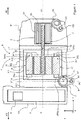
- the names “longitudinal”, “radial”, “front” and “rear” refer to the orientation, in an Oxyz orthonormal frame, of an electric compressor 1 illustrated in FIGS. FIGURES 1 to 3 .
- the axis Ox represents the longitudinal direction
- the axis Oy and the axis Oz represent radial directions of the object in question, in particular the electric compressor 1.
- a longitudinal plane is parallel to the plane Oxz or on the plane Oxy and a radial plane is parallel to the plane Oyz.
- the front and rear positions are defined along the longitudinal axis X.
- a radial position is defined as being located within a plane parallel to the plane Oyz.
- An electric compressor 1 according to the first aspect of the invention or according to any one of its improvements is more particularly intended to compress a refrigerating fluid FR flowing inside a refrigerant circuit 9 fitted to a motor vehicle, such as that illustrated on the FIGURE 4 .
- the electric compressor 1 can be used for the compression of fluids of different types, and the electric compressor 1 can be mounted on any type of circuit as mobile as fixed.
- the refrigerant circuit 9 with which the electric compressor 1 is intended to collaborate can equip any type of motorized vehicle, without restriction as to their type.
- the electric compressor 1 extends along the longitudinal axis X. It is understood here that the longitudinal axis X is the axis in which the electric compressor 1 has its largest dimension.
- the electric compressor is generally of cylindrical conformation whose axis of revolution coincides with the longitudinal axis X.
- the electric compressor 1 comprises a compression mechanism 2 which is intended to compress the refrigerant fluid FR admitted inside the electric compressor 1.
- the compression mechanism 2 comprises at least one movable element 21 which is rotated on itself to compress the refrigerant fluid FR.
- the compression mechanism 2 is a spiral mechanism comprising for example two spirals nested one inside the other, including a mobile spiral, forming the movable element 21, and a fixed spiral.
- the electric compressor 1 also comprises an electric motor 3 for driving the compression mechanism 2 in rotation.
- the electric motor 3 comprises a stator 31 which is a fixed element and a rotor 32 which is a member movable in rotation inside the stator. 31.
- the electric motor 3 also comprises a drive shaft 33 which extends along an axis of rotation A1 preferably parallel to, or even coincident with the longitudinal axis X.
- the drive shaft 33 is integral with the rotor 32.
- motor shaft 33 is also integral with the movable element 21 of the compression element 2.
- the electric compressor 1 further comprises a control module 4 which is intended to drive the electric motor 3, and in particular the rotation of the drive shaft 33.
- the control module 4 notably comprises an inverter 5 which makes it possible to convert available electrical energy. on board the motor vehicle in electrical energy adapted for the electric motor 3 of the electric compressor 1.
- the compression mechanism 2, the electric motor 3 and the control module 4 are aligned parallel to the axis of rotation A1. More specifically, the electric motor 3 is located in an axially intermediate position between the compression mechanism 2 and the control module 4. In other words, the electric motor 3 is interposed between the compression mechanism 2 and the control module 4 along. of the axis of rotation A1 of the electric motor 3.
- the left side is defined as forming the rear AR of the electric compressor 1 and the right side is defined as forming the front AV of the electric compressor 1.
- the control module 4 is located at the rear rear of the electric compressor 1 and the compression mechanism 2 is located at the front of the AV of the electric compressor 1.
- the compression mechanism 2, the electric motor 3 and the control module 4 are housed inside a housing 6 of the electric compressor 1.
- the housing 6 forms an enclosure for the housing and / or the protection of the compression mechanism 2, the electric motor 3 and the control module 4.
- the housing 6 is for example formed of an aluminum alloy.
- the housing 6 also includes not shown fastening means for fixing the electric compressor 1 to the motor vehicle on which it is mounted.
- the housing 6 comprises a first housing element 61 for storing the compression mechanism 2, a second housing element 62 for storing an electric motor 3 and a third housing element 63 for storing the control module 4.
- the elements case 61, 62, 63 and form cavities compatible with each other, so that, collectively, the housing elements 61, 62, 63 form a single cavity within which are completely housed the compression mechanism 2, the electric motor 3 and the control module 4, the refrigerant fluid circulating inside said single cavity.
- the third housing element 63 comprises a partition 631 separating the cavity of said third housing element 63 from the cavity of the second housing element 62, the cavity of the second housing element 62 and the cavity of the first housing element 61 forming together a single cavity.
- housing members 61, 62, 63 are assembled to each other by screwing, by interlocking, by snapping or any other means of assembly, preferably reversible.
- any of the housing elements 61, 62, 63 may be formed of a plastic material, such as a polycarbonate in particular.
- the housing 6 is equipped with an inlet port 7 of the refrigerant fluid FR inside the electric compressor 1.
- the inlet port 7 is arranged to allow a fluid circulation of the refrigerant fluid FR between the outside of the electric compressor and the interior of the electric compressor 1.
- the input port is the element of the housing 6 through which the refrigerant FR is admitted inside the electric compressor 1.
- the input port 7 is arranged to enable the electric compressor to be connected to the refrigerant circuit with which it is intended to collaborate, the inlet port 7 allowing the refrigerant to penetrate inside the electric compressor at the level of the second housing element 62.
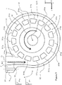
- the input port 7 is generally arranged in a cylindrical barrel which is formed around an input axis A2.
- the input axis A2 is taken inside a radial plane P1 of the electric compressor 1, the radial plane P1 being orthogonal to the axis of rotation A1.
- the input port 7 has an inlet orifice 71 of the refrigerant FR which extends orthogonally to the input axis A2.
- the input port 7 is arranged tangentially to the electric motor 3. More particularly, the input port 7 is tangent to the stator 31 of the electric motor 3. As a result, the input port 7 is arranged so that tangential to the motor shaft 33 of the electric motor 3. It is understood in this that the input axis A2 is tangential to a circle C inscribed in the radial plane P1 and centered on the axis of rotation A1, as is visible on the FIGURE 2 . In other words, the axis of rotation A1 and the input axis A2 are not intersecting with each other. These provisions are such that the refrigerant FR penetrating inside the electric compressor 1 through the input port 7 flows tangentially to the electric motor 3, and more particularly to the stator 31 of the electric motor 1.
- an angle formed by the input axis A2 and the tangent to the circle C inscribed in the radial plane P1 and taken at said input port and / or at the axis of the inlet A2 is between 0 ° and 45 ° to allow the refrigerating fluid FR to flow more easily when it enters the interior of the electric compressor 1 via said inlet port 7.
- the stator 31 comprises coils 311 at least partially surrounded around a core 312.
- the coils 311 are radially distributed around the rotation shaft 33 while being extended parallel to the longitudinal axis X.
- the coils 311 are arranged at equal distance from the longitudinal axis X.
- Each coil 311 comprises two coil heads 311a, 311b formed at each of the longitudinal ends of the coil 311.
- each coil 311 is equipped with a rear coil head 311a and a front coil head 311b, each coil head 311a, 311b forming a longitudinal end of the coil 311.
- the rear coil heads 311a are at least partly enclosed or intersecting with a rear plane P1a and the coil heads rear 311b are at least partly included or intersecting with a plane before P1b, the rear plane P1a and the front plane P1b being radial planes parallel to each other.
- the input port 7 is also arranged axially between the control module 4 and the stator 31. More particularly, the input port 7 is arranged between the control module 4 and the core 312.
- the input port 7 is formed inside a radial plane P1 which is interposed between the control module 4 and the rear radial plane P1a comprising the coil heads 311a, 311b.
- the input port 7 is tangent to the coil heads 311a, 311b which form the longitudinal ends of the core 312.
- the input port 7 is arranged facing the rear coil heads 311a and tangentially to the rear coil heads 311a, so that the radial plane P1 comprising the input port 7 and the rear radial plane P1a comprising the rear coil heads 311a are merged.
- the input port 7 is arranged vis-à-vis the rear coil heads 311a.
- the coil heads 311a, 311b being the areas of the coils 311 which tend to heat up the most during the implementation of the electric compressor 1, this results in an optimization of the cooling of the electric compressor 1. Moreover, this arrangement allows also to promote the contact between the refrigerant and the partition 631 carrier of the control module 4, so as to cool it more effectively.
- the input port 7 may be arranged slightly offset from the rear coil heads 311a, either on the side of the core 312 - in the direction of the compression mechanism 2 - or on the side of the control module 4. By slightly shifted, it is understood that the input port 7 is axially offset so that said input port 7 is axially attached against an axial end of the rear coil heads 311, or the side of the core 312, or the side of the control module 4.
- a direction of rotation S1 of the drive shaft 33 and a flow direction S2 of the refrigerant FR are for example both of the same direction relative to the axis of rotation A1 of the rotor 32, and in particular trigonometric senses as illustrated on the FIGURE 3 .
- the direction of rotation S1 and the direction of movement S2 are likely to be one and the other of the clockwise directions.
- the input port 7 is provided with a protrusion 8 which forms an outer projection with respect to the longitudinal axis X.
- the protrusion 8 preferably comprises a fastener 81 of a conduit that comprises the refrigerant circuit 9 illustrated on the FIGURE 4 .
- the fastener 81 is for example formed of a cylindrical orifice adapted to receive a finger or a screw that comprises a flange for fixing the conduit inside the inlet orifice 71.
- the fastener 81 extends radially outwardly of the electric compressor 1.
- the input port 7 advantageously equips the second housing element 62 while an outlet port 10 of the refrigerant fluid FR out of the electric compressor 1 equips the first housing element 61.
- the outlet port 10 is provided with an extension 101 which preferably comprises an assembly member 102 of a duct which comprises the refrigerant circuit 9 illustrated in FIG. FIGURE 4 .
- the FIGURE 4 illustrates an exemplary embodiment of a refrigerant circuit 9 FR according to the second aspect of the invention.
- the refrigerant circuit FR is closed and the refrigerant fluid FR circulates inside said refrigerant fluid circuit FR through ducts allowing fluid circulation of the refrigerant fluid FR.
- the refrigerant circuit 9 successively comprises, according to the flow direction S2 of the refrigerant fluid FR inside the refrigerant circuit 9, the electric compressor 1 according to the first aspect of the invention and as previously described for compressing the refrigerating fluid FR, a condenser or a gas cooler 91 for cooling the refrigerant FR, an expansion member 92 inside which the cooling fluid FR undergoes a lowering of its pressure and a heat exchanger 93.
- the heat exchanger 93 is housed inside a ventilation, heating and / or air conditioning installation 94 inside which a flow of air FA circulates.
- the heat exchanger 93 allows a heat transfer between the refrigerant fluid FR and the airflow FA coming into contact with it and / or passing through it.
- the heat exchanger 93 is used as an evaporator for cooling the airflow FA, during the passage of the air flow FA to the contact and / or part of the heat exchanger 93.
- the invention relates to an electric compressor 1, an inlet port 7 of the refrigerant fluid FR in said electric compressor 1 is arranged radially with respect to the axis of rotation A1 of the rotor 32 of the electric motor 3 resulting in rotation of the compression mechanism 2 of said electric compressor 1, said input port 7 being also arranged tangentially to the electric motor 3 and located between the control module 4 and an axial end 311a of a core 312 of the stator 31 located on the side of said control module 4, in order to facilitate the fluid flow of the refrigerating fluid FR entering the electric compressor 1.
Description
- La présente invention se rapporte aux compresseurs électriques équipant un véhicule automobile, par exemple, pour la circulation d'un fluide réfrigérant FR à l'intérieur d'un circuit de fluide réfrigérant FR du véhicule automobile. Elle a pour objet un tel compresseur électrique.
- Un véhicule automobile est couramment équipé d'un circuit de fluide réfrigérant FR qui est prévu pour modifier une température d'un flux d'air préalablement à son admission à l'intérieur d'un habitacle du véhicule automobile. Le circuit de fluide réfrigérant FR comprend notamment un compresseur pour comprimer un fluide réfrigérant FR qui circule à l'intérieur du circuit de fluide réfrigérant FR.
- Le compresseur est notamment un compresseur électrique qui comprend un mécanisme de compression entraîné par un moteur électrique, afin de mettre sous pression le fluide réfrigérant FR dans le circuit de fluide réfrigérant FR. Pour alimenter le moteur électrique, le compresseur électrique comprend en outre un module de commande permettant de convertir l'énergie électrique disponible à bord du véhicule automobile en une énergie électrique adaptée pour le moteur électrique du compresseur électrique.
- On connait notamment le document
EP2873858 qui décrit un tel compresseur électrique comprenant un boîtier logeant un mécanisme de compression du fluide réfrigérant FR. Le boîtier loge aussi le moteur électrique pour actionner le mécanisme de compression, le moteur électrique comprenant un rotor en rotation autour d'un axe de rotation et un stator comprenant des bobines électriques enroulées autour d'un noyau. Le boîtier loge aussi un module de commande pour piloter le moteur électrique. Le moteur électrique, le mécanisme de commande et le module de commande sont alignés suivant un axe longitudinal du compresseur électrique. Plus précisément, le moteur électrique est situé dans une position axialement intermédiaire entre le mécanisme de compression et le module de commande. - Le boitier comprend un port d'entrée du fluide réfrigérant FR dans le compresseur électrique. Le port d'entrée est le moyen par lequel le fluide réfrigérant FR est admis à l'intérieur du compresseur électrique. Dans un tel compresseur électrique, le port d'entrée est agencé de manière radiale par rapport à un axe de rotation du rotor, l'axe de rotation du rotor étant parallèle, voire confondu, à l'axe longitudinal du compresseur électrique. Autrement dit, le port d'entrée est compris à l'intérieur d'un plan radial qui est orthogonal à l'axe de rotation du rotor. De plus, suivant la direction axiale du compresseur électrique, le port d'entrée est situé en regard des bobines électriques du stator.
- Cette configuration n'est pas optimale car le fluide réfrigérant FR pénètre à l'intérieur du compresseur électrique selon une direction radiale, orthogonale à l'axe longitudinal du compresseur électrique. Il en découle que le fluide réfrigérant FR frappe un corps de bobine électrique situé axialement sensiblement au milieu des bobines, c'est-à-dire situé sensiblement à égale distance des extrémités longitudinales desdites bobines électriques. Il en résulte une perte de charge conséquente pour le fluide réfrigérant FR qu'il est souhaitable de minimiser. Il en résulte aussi une réduction du refroidissement des extrémités longitudinales des bobines alors que ces dernières sont les parties des bobines qui tendent à s'échauffer le plus. Consécutivement, il en résulte aussi un faible refroidissement du module de commande pouvant conduire à des défaillances du compresseur électrique.
- La présente invention a pour but de répondre au moins en partie aux problèmes précédents et de conduire en outre à d'autres avantages en proposant un nouveau compresseur électrique.
- Un autre but de la présente invention est d'optimiser le refroidissement d'un tel compresseur électrique, et plus particulièrement du moteur électrique et du module de commande.
- Un autre but est de proposer un compresseur électrique dont l'agencement permet de minimiser des pertes de charge lors de la circulation du fluide réfrigérant FR à l'intérieur du compresseur électrique.
- Un autre but est d'une manière générale d'améliorer une efficacité du compresseur électrique.
- Enfin, un autre but est de rendre plus compact un compresseur électrique afin notamment de faciliter un raccordement du compresseur électrique sur le circuit de fluide réfrigérant FR.
- Selon un premier aspect de l'invention, on atteint au moins un des buts précités avec un compresseur électrique d'un fluide réfrigérant, le compresseur électrique comprenant un boitier qui loge au moins :
- un mécanisme de compression du fluide réfrigérant ;
- un moteur électrique pour actionner le mécanisme de compression, le moteur électrique comprenant un rotor en rotation autour d'un axe de rotation et un stator comprenant des bobines électriques enroulées autour d'un noyau ;
- un module de commande pour piloter le moteur électrique, le moteur électrique étant situé dans une position axialement intermédiaire entre le mécanisme de compression et le module de commande.
- Le boitier comprend au moins un port d'entrée du fluide réfrigérant dans le compresseur électrique, ledit port d'entrée étant agencé de manière radiale par rapport à l'axe de rotation du rotor.
- Conformément à l'invention selon son premier aspect, le port d'entrée est agencé de manière tangentielle au moteur électrique et le port d'entrée est situé entre le module de commande et une extrémité axiale d'un noyau du stator située du côté dudit module de commande.
- Ainsi le compresseur électrique conforme au premier aspect de l'invention permet d'injecter le fluide réfrigérant à l'intérieur du boitier à proximité des parties du compresseur électrique qui dégagent le plus de chaleur lorsque le compresseur électrique est en fonctionnement. Par conséquent, le refroidissement du compresseur électrique est optimisé puisque le fluide réfrigérant circulant dans le boitier passe favorablement au niveau des extrémités axiales du noyau du stator et contre une paroi séparant le module de commande du moteur électrique.
- La configuration avantageuse du port d'entrée du compresseur électrique permet de faciliter l'injection du fluide réfrigérant dans le boitier et permet finalement de minimiser les pertes de charge du fluide réfrigérant : l'efficacité du compresseur électrique est améliorée.
- Le compresseur électrique conforme au premier aspect de l'invention peut comprendre avantageusement au moins un des perfectionnements ci-dessous, les caractéristiques techniques formant ces perfectionnements pouvant être prises seules ou en combinaison :
- le port d'entrée est tangent au stator. En d'autres termes, une direction d'écoulement du fluide réfrigérant traversant le port d'entrée du compresseur électrique est tangente au stator du moteur électrique pris au niveau dudit port d'entrée, c'est-à-dire au niveau d'une zone du stator située en regard du port d'entrée. Cette configuration avantageuse permet de faciliter l'écoulement du fluide réfrigérant lorsqu'il entre à l'intérieur du boitier du compresseur électrique. D'une manière plus générale, la direction d'écoulement du fluide réfrigérant traversant le port d'entrée du compresseur électrique forme un angle avec la tangente au stator prise au niveau dudit port d'entrée compris entre 0° et 45°. La direction d'écoulement du fluide réfrigérant dans le port d'entrée est définie par la direction d'extension du port d'entrée, c'est-à-dire la direction d'extension d'un conduit à l'intérieur duquel circule le fluide réfrigérant au niveau du port d'entrée ;
- le port d'entrée est tangent à l'extrémité axiale du noyau du stator. En d'autres termes, la direction d'écoulement du fluide réfrigérant traversant le port d'entrée du compresseur électrique est tangente à l'extrémité axiale du noyau du stator prise au niveau dudit port d'entrée, c'est-à-dire au niveau d'une zone de l'extrémité axiale du noyau située en regard du port d'entrée. Cette configuration avantageuse permet de faciliter l'écoulement du fluide réfrigérant lorsqu'il entre à l'intérieur du boitier du compresseur électrique. D'une manière plus générale, la direction d'écoulement du fluide réfrigérant traversant le port d'entrée du compresseur électrique forme un angle avec la tangente à l'extrémité axiale du noyau du stator prise au niveau dudit port d'entrée compris entre 0° et 45°. La direction d'écoulement du fluide réfrigérant dans le port d'entrée est définie par la direction d'extension du port d'entrée, c'est-à-dire la direction d'extension d'un conduit à l'intérieur duquel circule le fluide réfrigérant au niveau du port d'entrée ;
- le port d'entrée est ménagé en vis-à-vis de l'extrémité axiale du noyau du stator. Selon une première configuration avantageuse, le port d'entrée est situé axialement au niveau de l'extrémité axiale du noyau du stator, ledit port d'entrée débouchant entièrement en regard d'une face dudit noyau prise au niveau de ladite extrémité axiale du noyau. Cette première configuration permet au fluide réfrigérant sortant du port d'entrée de pénétrer dans le boitier du compresseur électrique au niveau de l'extrémité axiale du noyau du stator, du côté du stator. Selon une deuxième configuration avantageuse, le port d'entrée est situé axialement entre l'extrémité axiale du noyau du stator et le module de commande. Cette deuxième configuration permet au fluide réfrigérant sortant du port d'entrée de pénétrer dans le boitier du compresseur électrique au niveau de l'extrémité axiale du noyau du stator, du côté du module de commande, au niveau d'une cavité du boitier située entre l'extrémité axiale du noyau du stator et le module de commande. En d'autres termes, cette deuxième configuration permet de faire pénétrer le fluide réfrigérant de manière à lécher l'extrémité axiale du noyau du stator, ledit stator étant situé axialement contre ou à légèrement en retrait du port d'entrée. Selon une troisième configuration intermédiaire à la première et la deuxième configuration, le porté d'entrée est situé axialement à cheval au niveau de l'extrémité axiale du noyau du stator. En d'autres termes, une partie du port d'entrée est située en regard de l'extrémité axiale du noyau et une partie complémentaire dudit port d'entrée est située axialement au-delà de ladite extrémité axiale, au niveau de la cavité du boitier située entre l'extrémité axiale du noyau du stator et le module de commande ;
- le port d'entrée est agencé en un fut cylindrique d'axe d'entrée qui est tangent à un cercle inscrit dans un plan radial et centré sur l'axe de rotation. En d'autres termes, le porte d'entrée et/ou le fut cylindrique est tangent au cercle inscrit dans le plan radial et centré sur l'axe de rotation du compresseur électrique. Le plan radial est perpendiculaire à l'axe de rotation du rotor. D'une manière plus générale, le port d'entrée forme un angle avec la tangente au cercle prise au niveau dudit port d'entrée compris entre 0° et 45° ;
- le port d'entrée comprend une protrusion comprenant un organe de fixation apte à coopérer avec un organe de fixation complémentaire équipant un moyen de fixation d'un conduit. L'organe de fixation permet de fixer solidairement un conduit permettant la circulation fluidique du fluide réfrigérant jusqu'au port d'entrée afin de connecter le compresseur électrique conforme au premier aspect de l'invention à un circuit de fluide réfrigérant. Le moyen de fixation peut être de tout type, avantageusement il s'agit d'une vis de fixation permettant de visser en collier de serrage du conduit sur le port d'entrée ;
- le mécanisme de compression est un mécanisme à spirales.
- Selon un deuxième aspect de l'invention, il est proposé un circuit de fluide réfrigérant comprenant un compresseur électrique conforme au premier aspect de l'invention ou à l'un quelconque de ses perfectionnements, un refroidisseur de gaz, un organe de détente et au moins un échangeur de chaleur ;
- De manière avantageuse, le rotor du compresseur électrique tourne selon un sens de rotation, le fluide réfrigérant circulant selon un sens de circulation à l'intérieur du circuit de fluide réfrigérant, le sens de rotation et le sens de circulation étant de même sens au niveau du port d'entrée.
- Des modes de réalisation variés de l'invention sont prévus, intégrant selon l'ensemble de leurs combinaisons possibles les différentes caractéristiques optionnelles exposées ici.
- D'autres caractéristiques et avantages de l'invention apparaîtront encore au travers de la description qui suit d'une part, et de plusieurs exemples de réalisation donnés à titre indicatif et non limitatif en référence aux dessins schématiques annexés d'autre part, sur lesquels :
- la
FIGURE 1 est une vue de côté d'un compresseur électrique selon l'invention, - la
FIGURE 2 est une vue de dessus du compresseur électrique illustré sur laFIGURE 1 , - la
FIGURE 3 est une vue d'une coupe radiale du compresseur électrique illustré sur lesFIGURES 1 et2 , - la
FIGURE 4 est une illustration schématique d'un circuit de fluide réfrigérant FR comprenant un compresseur électrique représenté sur lesFIGURES 1 à 3 . - Bien entendu, les caractéristiques, les variantes et les différentes formes de réalisation de l'invention peuvent être associées les unes avec les autres, selon diverses combinaisons, dans la mesure où elles ne sont pas incompatibles ou exclusives les unes des autres. On pourra notamment imaginer des variantes de l'invention ne comprenant qu'une sélection de caractéristiques décrites par la suite de manière isolées des autres caractéristiques décrites, si cette sélection de caractéristiques est suffisante pour conférer un avantage technique ou pour différencier l'invention par rapport à l'état de la technique antérieur.
- En particulier toutes les variantes et tous les modes de réalisation décrits sont combinables entre eux si rien ne s'oppose à cette combinaison sur le plan technique.
- Sur les figures, les éléments communs à plusieurs figures conservent la même référence.
- Dans la suite de la description et des revendications, les dénominations « longitudinale », « radiale », « avant » et « arrière » se réfèrent à l'orientation, dans un repère orthonormé Oxyz, d'un compresseur électrique 1 illustré sur les
FIGURES 1 à 3 . Dans ce repère, l'axe Ox représente la direction longitudinale, l'axe Oy et l'axe Oz représentent des directions radiales de l'objet considéré, notamment le compresseur électrique 1. Dans ce repère, un plan longitudinal est parallèle au plan Oxz ou au plan Oxy et un plan radial est parallèle au plan Oyz. Les positions avant et arrière sont définies le long de l'axe longitudinal X. Une position radiale est définie comme étant située à l'intérieur d'un plan parallèle au plan Oyz. - Un compresseur électrique 1 conforme au premier aspect de l'invention ou selon l'un quelconque de ses perfectionnements est plus particulièrement destiné à comprimer un fluide réfrigérant FR circulant à l'intérieur d'un circuit de fluide réfrigérant 9 équipant un véhicule automobile, tel qu'illustré sur la
FIGURE 4 . D'une manière générale, le compresseur électrique 1 peut être utilisé pour la compression de fluides de différentes natures, et le compresseur électrique 1 peut être monté sur tout type de circuit aussi bien mobile que fixe. Par ailleurs, le circuit de fluide réfrigérant 9 avec lequel le compresseur électrique 1 est destiné à collaborer peut équiper tout type de véhicule motorisé, sans restriction quant à leur type. - Comme illustré sur la
FIGURE 1 , le compresseur électrique 1 s'étend selon l'axe longitudinal X. On comprend ici que l'axe longitudinal X est l'axe selon lequel le compresseur électrique 1 comporte sa plus grande dimension. Le compresseur électrique est globalement de conformation cylindrique dont un axe de révolution est confondu avec l'axe longitudinal X. - Le compresseur électrique 1 comprend un mécanisme de compression 2 qui est destiné à comprimer le fluide réfrigérant FR admis à l'intérieur du compresseur électrique 1. Le mécanisme de compression 2 comprend au moins un élément mobile 21 qui est entraîné en rotation sur lui-même pour comprimer le fluide réfrigérant FR. Préférentiellement, le mécanisme de compression 2 est un mécanisme à spirales comprenant par exemple deux spirales imbriquées l'une dans l'autre, dont une spirale mobile, formant l'élément mobile 21, et une spirale fixe.
- Le compresseur électrique 1 comprend aussi un moteur électrique 3 pour entraîner en rotation le mécanisme de compression 2. Le moteur électrique 3 comprend un stator 31 qui est un élément fixe et un rotor 32 qui est un élément mobile en rotation à l'intérieur du stator 31. Le moteur électrique 3 comprend également un arbre moteur 33 qui s'étend le long d'un axe de rotation A1 préférentiellement parallèle, voire confondu avec l'axe longitudinal X. L'arbre moteur 33 est solidaire du rotor 32. L'arbre moteur 33 est également solidaire de l'élément mobile 21 de l'élément de compression 2.
- Le compresseur électrique 1 comprend encore un module de commande 4 qui est destiné à piloter le moteur électrique 3, et notamment la rotation de l'arbre moteur 33. Le module de commande 4 comprend notamment un onduleur 5 qui permet de convertir une énergie électrique disponible à bord du véhicule automobile en une énergie électrique adaptée pour le moteur électrique 3 du compresseur électrique 1.
- Le mécanisme de compression 2, le moteur électrique 3 et le module de commande 4 sont alignés parallèlement à l'axe de rotation A1. Plus précisément, le moteur électrique 3 est situé dans une position axialement intermédiaire entre le mécanisme de compression 2 et le module de commande 4. Autrement dit, le moteur électrique 3 est interposé entre le mécanisme de compression 2 et le module de commande 4 le long de l'axe de rotation A1 du moteur électrique 3. Sur la
FIGURE 1 , le côté gauche est défini comme formant l'arrière AR du compresseur électrique 1 et le côté droit est défini comme formant l'avant AV du compresseur électrique 1. Selon cette configuration, le module de commande 4 est situé à l'arrière AR du compresseur électrique 1 et le mécanisme de compression 2 est situé à l'avant AV du compresseur électrique 1. - Le mécanisme de compression 2, le moteur électrique 3 et le module de commande 4 sont logés à l'intérieur d'un boîtier 6 du compresseur électrique 1. Le boîtier 6 forme une enceinte pour le logement et/ou la protection du mécanisme de compression 2, du moteur électrique 3 et du module de commande 4. Le boîtier 6 est par exemple formé d'un alliage d'aluminium. Le boitier 6 comprend aussi des moyens de fixation non représentés afin de fixer le compresseur électrique 1 au véhicule automobile sur lequel il est monté.
- Le boîtier 6 comprend un premier élément de boîtier 61 pour le stockage du mécanisme de compression 2, un deuxième élément de boîtier 62 pour le stockage de moteur électrique 3 et un troisième élément de boîtier 63 pour le stockage du module de commande 4. Les éléments de boitier 61, 62, 63 forment ainsi des cavités compatibles les unes avec les autres, de sorte que, collectivement, les éléments de boitier 61, 62, 63 forment une unique cavité à l'intérieur de laquelle sont entièrement logés le mécanisme de compression 2, le moteur électrique 3 et le module de commande 4, le fluide réfrigérant pouvant circuler à l'intérieur de ladite unique cavité. De préférence, le troisième élément de boitier 63 comprend une cloison 631 séparant la cavité dudit troisième élément de boitier 63 de la cavité du deuxième élément de boitier 62, la cavité du deuxième élément de boitier 62 et la cavité du premier élément de boitier 61 formant ensemble une unique cavité. De préférence ces éléments de boîtier 61, 62, 63 sont assemblés les uns aux autres par vissage, par emboîtement, par encliquetage ou tout autre moyen d'assemblage, préférentiellement réversible. Selon une forme de réalisation, l'un quelconque des éléments de boîtier 61, 62, 63 est susceptible d'être formée en une matière plastique, tel qu'un polycarbonate notamment.
- Le boîtier 6 est équipé d'un port d'entrée 7 du fluide réfrigérant FR à l'intérieur du compresseur électrique 1. Le port d'entrée 7 est agencé pour permettre une circulation fluidique du fluide réfrigérant FR entre l'extérieur du compresseur électrique et l'intérieur du compresseur électrique 1. Le port d'entrée est l'élément du boîtier 6 par lequel le fluide réfrigérant FR est admis à l'intérieur du compresseur électrique 1. En d'autres termes, le port d'entrée 7 est agencé pour permettre de connecter le compresseur électrique au circuit de fluide réfrigérant avec lequel il est destiné à collaborer, le port d'entrée 7 permettant au fluide réfrigérant de pénétrer à l'intérieur du compresseur électrique au niveau du deuxième élément de boitier 62. Le port d'entrée 7 est globalement agencé en un fût cylindrique qui est ménagé autour d'un axe d'entrée A2. L'axe d'entrée A2 est pris à l'intérieur d'un plan radial P1 du compresseur électrique 1, le plan radial P1 étant orthogonal à l'axe de rotation A1. Le port d'entrée 7 comporte un orifice d'entrée 71 du fluide réfrigérant FR qui s'étend orthogonalement à l'axe d'entrée A2.
- Selon la présente invention, et en se reportant également sur la
FIGURE 2 , le port d'entrée 7 est agencé de manière tangentielle au moteur électrique 3. Plus particulièrement, le port d'entrée 7 est tangent au stator 31 du moteur électrique 3. Il en résulte que le port d'entrée 7 est agencé de manière tangentielle à l'arbre moteur 33 du moteur électrique 3. On comprend en cela que l'axe d'entrée A2 est tangent à un cercle C inscrit dans le plan radial P1 et centré sur l'axe de rotation A1, tel que cela est visible sur laFIGURE 2 . Autrement dit, l'axe de rotation A1 et l'axe d'entrée A2 ne sont pas sécants l'un avec l'autre. Ces dispositions sont telles que le fluide réfrigérant FR pénétrant à l'intérieur du compresseur électrique 1 par l'intermédiaire du port d'entrée 7 s'écoule de manière tangentielle au moteur électrique 3, et plus particulièrement au stator 31 du moteur électrique 1. - D'une manière plus générale, un angle formé par l'axe d'entrée A2 et la tangente au cercle C inscrit dans le plan radial P1 et prise au niveau dudit port d'entrée et/ou au niveau de l'axe d'entrée A2 est compris entre 0° et 45° afin de permettre au fluide réfrigérant FR de s'écouler plus facilement lorsqu'il pénètre à l'intérieur du compresseur électrique 1 par l'intermédiaire dudit port d'entrée 7.
- Sur la
FIGURE 3 , le stator 31 comprend des bobines 311 entourées au moins partiellement autour d'un noyau 312. Les bobines 311 sont radialement réparties autour de l'arbre de rotation 33 en étant étendues parallèlement à l'axe longitudinal X. Les bobines 311 sont disposées à égale distance de l'axe longitudinal X. Chaque bobine 311 comprend deux têtes de bobines 311a, 311b ménagées à chacune des extrémités longitudinales de la bobine 311. Autrement dit, chaque bobine 311 est équipé d'une tête de bobine arrière 311a et d'une tête de bobine avant 311b, chaque tête de bobine 311a, 311b formant une extrémité longitudinale de la bobine 311. De préférence, les têtes de bobines arrière 311a sont au moins en partie incluses ou sécantes avec un plan arrière P1a et les têtes de bobines arrière 311b sont au moins en partie incluses ou sécantes avec un plan avant P1b, le plan arrière P1a et le plan avant P1b étant des plans radiaux parallèles entre eux. - De plus, de manière avantageuse, le port d'entrée 7 est aussi disposé axialement entre le module de commande 4 et le stator 31. Plus particulièrement, le port d'entrée 7 est disposé entre le module de commande 4 et le noyau 312.
- Selon une forme de réalisation de la présente invention, le port d'entrée 7 est ménagé à l'intérieur d'un plan radial P1 qui est interposé entre le module de commande 4 et le plan radial arrière P1a comprenant les têtes de bobines 311a, 311b. Autrement dit, le port d'entrée 7 est tangent aux têtes de bobines 311a, 311b qui forment les extrémités longitudinales du noyau 312.
- Selon la variante illustrée sur la
FIGURE 3 , le port d'entrée 7 est ménagé en regard des têtes de bobines arrière 311a et de manière tangentielle aux têtes de bobines arrière 311a, de telle sorte que le plan radial P1 comprenant le port d'entrée 7 et le plan radial arrière P1a comprenant les têtes de bobines arrière 311a sont confondus. Autrement dit, le port d'entrée 7 est ménagé en vis-à-vis des têtes de bobines arrière 311a. Ces dispositions sont telles que le fluide réfrigérant FR pénétrant à l'intérieur du compresseur électrique 1 par l'intermédiaire du port d'entrée 7 arrose en premier lieu les têtes de bobines arrière 311a, ce qui permet de les refroidir efficacement. Les têtes de bobines 311a, 311b étant les zones des bobines 311 qui tendent à s'échauffer le plus lors de la mise en œuvre du compresseur électrique 1, il en résulte une optimisation du refroidissement du compresseur électrique 1. Par ailleurs, cette disposition permet également de favoriser le contact entre le fluide réfrigérant et la cloison 631 porteuse du module de commande 4, de manière à refroidir plus efficacement celui-ci. - Éventuellement, le port d'entrée 7 peut être ménagé de manière légèrement décalée par rapport aux têtes de bobines arrière 311a, soit du côté du noyau 312 - dans la direction du mécanisme de compression 2 - soit du côté du module de commande 4. Par légèrement décalé, on comprend que le port d'entrée 7 est axialement décalé de manière à ce que ledit port d'entrée 7 soit axialement accolé contre une extrémité axiale des têtes de bobines arrière 311, soit du côté du noyau 312, soit du côté du module de commande 4.
- Comme visible sur la
FIGURE 3 , un sens de rotation S1 de l'arbre moteur 33 et un sens de circulation S2 du fluide réfrigérant FR sont par exemple l'un et l'autre de même sens par rapport à l'axe de rotation A1 du rotor 32, et notamment des sens trigonométriques tels qu'illustrée sur laFIGURE 3 . Selon une autre forme de réalisation, le sens de rotation S1 et le sens de circulation S2 sont susceptibles d'être l'un et l'autre des sens horaires. - Le port d'entrée 7 est pourvu d'une protrusion 8 qui forme une saillie extérieure par rapport à l'axe longitudinal X. La protrusion 8 comprend de préférence un organe de fixation 81 d'un conduit que comprend le circuit de fluide réfrigérant 9 illustré sur la
FIGURE 4 . L'organe de fixation 81 est par exemple formé d'un orifice cylindrique apte à recevoir un doigt ou une vis que comporte une bride de fixation du conduit à l'intérieur de l'orifice d'entrée 71. L'organe de fixation 81 s'étend radialement vers l'extérieur du compresseur électrique 1. - On note également que le port d'entrée 7 équipe avantageusement le deuxième élément de boîtier 62 tandis qu'un port de sortie 10 du fluide réfrigérant FR hors du compresseur électrique 1 équipe le premier élément de boîtier 61. A l'instar du port d'entrée 7, le port de sortie 10 est pourvu d'une extension 101 qui comprend de préférence un organe d'assemblage 102 d'un conduit que comprend le circuit de fluide réfrigérant 9 illustré sur la
FIGURE 4 . - La
FIGURE 4 illustre un exemple de réalisation d'un circuit 9 de fluide réfrigérant FR conforme au deuxième aspect de l'invention. Le circuit 9 de fluide réfrigérant FR est fermé et le fluide réfrigérant FR circule à l'intérieur dudit circuit 9 de fluide réfrigérant FR grâce à des conduits permettant une circulation fluidique du fluide réfrigérant FR. - Dans l'exemple de réalisation illustré sur la
FIGURE 4 , le circuit de fluide réfrigérant 9 comprend successivement, suivant le sens de circulation S2 du fluide réfrigérant FR à l'intérieur du circuit de fluide réfrigérant 9, le compresseur électrique 1 conforme au premier aspect de l'invention et tel que décrit précédemment pour comprimer le fluide réfrigérant FR, un condenseur ou un refroidisseur de gaz 91 pour refroidir le fluide réfrigérant FR, un organe de détente 92 à l'intérieur duquel le fluide réfrigérant FR subit un abaissement de sa pression et un échangeur de chaleur 93. - L'échangeur de chaleur 93 est logé à l'intérieur d'une installation 94 de ventilation, de chauffage et/ou de climatisation à l'intérieur de laquelle circule un flux d'air FA. L'échangeur de chaleur 93 permet un transfert thermique entre le fluide réfrigérant FR et le flux d'air FA venant à son contact et/ou le traversant. Selon le mode de fonctionnement du circuit de fluide réfrigérant 9 décrit ci-dessus, l'échangeur de chaleur 93 est utilisé comme évaporateur pour refroidir le flux d'air FA, lors du passage du flux d'air FA au contact et/ou de part en part de l'échangeur de chaleur 93.
- En synthèse, l'invention concerne un compresseur électrique 1 dont un port d'entrée 7 du fluide réfrigérant FR dans ledit compresseur électrique 1 est agencé de manière radiale par rapport à l'axe de rotation A1 du rotor 32 du moteur électrique 3 entrainant en rotation le mécanisme de compression 2 dudit compresseur électrique 1, ledit port d'entrée 7 étant aussi agencé de manière tangentielle au moteur électrique 3 et situé entre le module de commande 4 et une extrémité axiale 311a d'un noyau 312 du stator 31 située du côté dudit module de commande 4, afin de faciliter l'écoulement fluidique du fluide réfrigérant FR pénétrant dans le compresseur électrique 1.
- Bien sûr, l'invention n'est pas limitée aux exemples qui viennent d'être décrits et de nombreux aménagements peuvent être apportés à ces exemples sans sortir du cadre de l'invention telle que définie par les revendications.
Claims (9)
- Compresseur électrique (1) d'un fluide réfrigérant (FR), le compresseur électrique (1) comprenant un boitier (6) qui loge au moins :- un mécanisme de compression (2) du fluide réfrigérant (FR) ;- un moteur électrique (3) pour actionner le mécanisme de compression (2), le moteur électrique (2) comprenant un rotor (32) en rotation autour d'un axe de rotation (A1) et un stator (31) comprenant des bobines électriques (311) enroulées autour d'un noyau (312) ;- un module de commande (4) pour piloter le moteur électrique (3), le moteur électrique (3) étant situé dans une position axialement intermédiaire entre le mécanisme de compression (2) et le module de commande (4) ;le boitier (6) comprenant au moins un port d'entrée (7) du fluide réfrigérant (FR) dans le compresseur électrique (1), ledit port d'entrée (7) étant agencé de manière radiale par rapport à l'axe de rotation (A1) du rotor (32), caractérisé en ce que le port d'entrée (7) est agencé de manière tangentielle au moteur électrique (3) et en ce que le port d'entrée (7) est situé entre le module de commande (4) et une extrémité axiale (311a) d'un noyau (312) du stator (31) située du côté dudit module de commande (4).
- Compresseur électrique (1) selon la revendication précédente, dans lequel le port d'entrée (7) est tangent au stator (31).
- Compresseur électrique (1) selon l'une quelconque des revendications précédentes, dans lequel le port d'entrée (7) est tangent à l'extrémité axiale (311a) du noyau (312) du stator (31).
- Compresseur électrique (1) selon la revendication 3, dans lequel le port d'entrée (7) est ménagé en vis-à-vis de l'extrémité axiale (311a) du noyau (312) du stator (31).
- Compresseur électrique (1) selon l'une quelconque des revendications précédentes, dans lequel le port d'entrée (7) est agencé en un fût cylindrique d'axe d'entrée (A2) qui est tangent à un cercle (C) inscrit dans un plan radial (P1) et centré sur l'axe de rotation (A1).
- Compresseur électrique (1) selon l'une quelconque des revendications précédentes, dans lequel le port d'entrée (7) comprend une protrusion (8) comprenant un organe de fixation (81) apte à coopérer avec un organe de fixation complémentaire équipant un moyen de fixation d'un conduit.
- Compresseur électrique (1) selon l'une quelconque des revendications précédentes, dans lequel le mécanisme de compression (2) est un mécanisme à spirales.
- Circuit de fluide réfrigérant (9) comprenant un compresseur électrique (1) selon l'une quelconque des revendications précédentes, un refroidisseur de gaz (91), un organe de détente (92) et au moins un échangeur de chaleur (93).
- Circuit de fluide réfrigérant (9) selon la revendication 8, comprenant un compresseur électrique (1) dont le rotor (32) tourne selon un sens de rotation (S1), le fluide réfrigérant (FR) circulant à l'intérieur du circuit de fluide réfrigérant (9) selon un sens de circulation (S2), dans lequel le sens de rotation (S1) du rotor (32) et le sens de circulation (S2) du fluide réfrigérant (FR) sont de même sens au niveau du port d'entrée (7).
Applications Claiming Priority (1)
| Application Number | Priority Date | Filing Date | Title |
|---|---|---|---|
| FR1753658A FR3065758B1 (fr) | 2017-04-27 | 2017-04-27 | Compresseur electrique |
Publications (2)
| Publication Number | Publication Date |
|---|---|
| EP3396162A1 EP3396162A1 (fr) | 2018-10-31 |
| EP3396162B1 true EP3396162B1 (fr) | 2019-12-11 |
Family
ID=59070924
Family Applications (1)
| Application Number | Title | Priority Date | Filing Date |
|---|---|---|---|
| EP18167339.3A Active EP3396162B1 (fr) | 2017-04-27 | 2018-04-13 | Compresseur électrique |
Country Status (2)
| Country | Link |
|---|---|
| EP (1) | EP3396162B1 (fr) |
| FR (1) | FR3065758B1 (fr) |
Family Cites Families (4)
| Publication number | Priority date | Publication date | Assignee | Title |
|---|---|---|---|---|
| US6908290B2 (en) * | 2003-05-01 | 2005-06-21 | Visteon Global Technologies, Inc. | Air conditioning compressor having reduced suction pulsation |
| JP5018451B2 (ja) * | 2007-12-18 | 2012-09-05 | 株式会社豊田自動織機 | 電動圧縮機 |
| WO2013172189A1 (fr) * | 2012-05-18 | 2013-11-21 | 株式会社ヴァレオジャパン | Compresseur électrique |
| FR3023328B1 (fr) * | 2014-07-07 | 2019-03-22 | Valeo Japan Co., Ltd. | Plaque d'un compresseur electrique et compresseur electrique comprenant une telle plaque |
-
2017
- 2017-04-27 FR FR1753658A patent/FR3065758B1/fr not_active Expired - Fee Related
-
2018
- 2018-04-13 EP EP18167339.3A patent/EP3396162B1/fr active Active
Non-Patent Citations (1)
| Title |
|---|
| None * |
Also Published As
| Publication number | Publication date |
|---|---|
| FR3065758B1 (fr) | 2019-05-03 |
| FR3065758A1 (fr) | 2018-11-02 |
| EP3396162A1 (fr) | 2018-10-31 |
Similar Documents
| Publication | Publication Date | Title |
|---|---|---|
| EP3004778B1 (fr) | Module de connexion, echangeur thermique, et ensemble d'echange thermique correspondant | |
| FR2991009A1 (fr) | Boitier de compresseur electrique comprenant un dispositif de dissipation, et compresseur comportant un tel boitier | |
| WO2017187046A1 (fr) | Systeme de gestion d'air d'admission pour un moteur thermique de véhicule automobile | |
| WO2022096204A1 (fr) | Module de refroidissement pour vehicule automobile electrique ou hybride a turbomachine tangentielle avec echangeur thermique supplementaire | |
| EP3396162B1 (fr) | Compresseur électrique | |
| WO2010063897A1 (fr) | Echangeur de chaleur à spires et dispositif de climatisation comprenant un tel échangeur de chaleur. | |
| WO2018060615A1 (fr) | Système de gestion d'air d'admission pour un moteur thermique de véhicule automobile | |
| WO2022106147A1 (fr) | Module de refroidissement pour véhicule automobile électrique ou hybride à turbomachine tangentielle avec échangeur de chaleur supplémentaire | |
| WO2022053501A1 (fr) | Module d'échange thermique et véhicule automobile correspondant | |
| WO2022207837A1 (fr) | Dispositif de chauffage, ventilation et/ou climatisation pour véhicule automobile | |
| FR3055366B1 (fr) | Systeme de gestion d'air d'admission pour un moteur thermique de vehicule automobile | |
| WO2022043586A1 (fr) | Module de refroidissement pour véhicule automobile électrique à turbomachine tangentielle | |
| FR3132468A1 (fr) | Dispositif de gestion thermique pour véhicule automobile électrique ou hybride | |
| WO2016005890A1 (fr) | Plaque d'un compresseur électrique et compresseur électrique comprenant une telle plaque | |
| WO2022023012A1 (fr) | Module de refroidissement pour véhicule automobile électrique ou hybride | |
| WO2024083565A1 (fr) | Module de refroidissement pour véhicule automobile électrique ou hybride | |
| EP4164904A1 (fr) | Module de refroidissement pour véhicule automobile électrique ou hybride à turbomachine tangentielle | |
| EP4314563A1 (fr) | Module de refroidissement pour vehicule automobile electrique ou hybride a turbomachine tangentielle | |
| WO2022058214A1 (fr) | Ensemble de modules de refroidissement à turbomachine tangentielle pour face avant de véhicule automobile électrique ou hybride | |
| FR2998733A1 (fr) | Dispositif d'entrainement d'un compresseur electrique et compresseur electrique comprenant un tel dispositif | |
| EP3942678A1 (fr) | Arbre creux de rotor divise longitudinalement comportant au moins une ailette forgee s'etendant a l'interieur | |
| FR3121076A1 (fr) | Module de refroidissement pour véhicule automobile électrique ou hybride à turbomachine tangentielle avec refroidissement de l’électronique de puissance | |
| WO2019150051A1 (fr) | Dispositif de ventilation pour vehicule automobile | |
| FR2831930A1 (fr) | Groupe moto-ventilateur comportant un module de commande integre universel | |
| FR2814707A1 (fr) | Radiateur cylindrique pour moteur a combustion |
Legal Events
| Date | Code | Title | Description |
|---|---|---|---|
| PUAI | Public reference made under article 153(3) epc to a published international application that has entered the european phase |
Free format text: ORIGINAL CODE: 0009012 |
|
| STAA | Information on the status of an ep patent application or granted ep patent |
Free format text: STATUS: THE APPLICATION HAS BEEN PUBLISHED |
|
| AK | Designated contracting states |
Kind code of ref document: A1 Designated state(s): AL AT BE BG CH CY CZ DE DK EE ES FI FR GB GR HR HU IE IS IT LI LT LU LV MC MK MT NL NO PL PT RO RS SE SI SK SM TR |
|
| AX | Request for extension of the european patent |
Extension state: BA ME |
|
| STAA | Information on the status of an ep patent application or granted ep patent |
Free format text: STATUS: REQUEST FOR EXAMINATION WAS MADE |
|
| 17P | Request for examination filed |
Effective date: 20190415 |
|
| RBV | Designated contracting states (corrected) |
Designated state(s): AL AT BE BG CH CY CZ DE DK EE ES FI FR GB GR HR HU IE IS IT LI LT LU LV MC MK MT NL NO PL PT RO RS SE SI SK SM TR |
|
| GRAP | Despatch of communication of intention to grant a patent |
Free format text: ORIGINAL CODE: EPIDOSNIGR1 |
|
| STAA | Information on the status of an ep patent application or granted ep patent |
Free format text: STATUS: GRANT OF PATENT IS INTENDED |
|
| RIC1 | Information provided on ipc code assigned before grant |
Ipc: F04C 29/12 20060101ALI20190523BHEP Ipc: F04B 39/06 20060101ALI20190523BHEP Ipc: F04C 23/00 20060101AFI20190523BHEP Ipc: F04C 29/04 20060101ALI20190523BHEP |
|
| INTG | Intention to grant announced |
Effective date: 20190624 |
|
| GRAS | Grant fee paid |
Free format text: ORIGINAL CODE: EPIDOSNIGR3 |
|
| GRAA | (expected) grant |
Free format text: ORIGINAL CODE: 0009210 |
|
| STAA | Information on the status of an ep patent application or granted ep patent |
Free format text: STATUS: THE PATENT HAS BEEN GRANTED |
|
| AK | Designated contracting states |
Kind code of ref document: B1 Designated state(s): AL AT BE BG CH CY CZ DE DK EE ES FI FR GB GR HR HU IE IS IT LI LT LU LV MC MK MT NL NO PL PT RO RS SE SI SK SM TR |
|
| REG | Reference to a national code |
Ref country code: GB Ref legal event code: FG4D Free format text: NOT ENGLISH |
|
| REG | Reference to a national code |
Ref country code: CH Ref legal event code: EP |
|
| REG | Reference to a national code |
Ref country code: AT Ref legal event code: REF Ref document number: 1212459 Country of ref document: AT Kind code of ref document: T Effective date: 20191215 |
|
| REG | Reference to a national code |
Ref country code: DE Ref legal event code: R096 Ref document number: 602018001539 Country of ref document: DE |
|
| REG | Reference to a national code |
Ref country code: IE Ref legal event code: FG4D Free format text: LANGUAGE OF EP DOCUMENT: FRENCH |
|
| REG | Reference to a national code |
Ref country code: NL Ref legal event code: MP Effective date: 20191211 |
|
| REG | Reference to a national code |
Ref country code: LT Ref legal event code: MG4D |
|
| PG25 | Lapsed in a contracting state [announced via postgrant information from national office to epo] |
Ref country code: NO Free format text: LAPSE BECAUSE OF FAILURE TO SUBMIT A TRANSLATION OF THE DESCRIPTION OR TO PAY THE FEE WITHIN THE PRESCRIBED TIME-LIMIT Effective date: 20200311 Ref country code: LT Free format text: LAPSE BECAUSE OF FAILURE TO SUBMIT A TRANSLATION OF THE DESCRIPTION OR TO PAY THE FEE WITHIN THE PRESCRIBED TIME-LIMIT Effective date: 20191211 Ref country code: GR Free format text: LAPSE BECAUSE OF FAILURE TO SUBMIT A TRANSLATION OF THE DESCRIPTION OR TO PAY THE FEE WITHIN THE PRESCRIBED TIME-LIMIT Effective date: 20200312 Ref country code: SE Free format text: LAPSE BECAUSE OF FAILURE TO SUBMIT A TRANSLATION OF THE DESCRIPTION OR TO PAY THE FEE WITHIN THE PRESCRIBED TIME-LIMIT Effective date: 20191211 Ref country code: LV Free format text: LAPSE BECAUSE OF FAILURE TO SUBMIT A TRANSLATION OF THE DESCRIPTION OR TO PAY THE FEE WITHIN THE PRESCRIBED TIME-LIMIT Effective date: 20191211 Ref country code: BG Free format text: LAPSE BECAUSE OF FAILURE TO SUBMIT A TRANSLATION OF THE DESCRIPTION OR TO PAY THE FEE WITHIN THE PRESCRIBED TIME-LIMIT Effective date: 20200311 Ref country code: FI Free format text: LAPSE BECAUSE OF FAILURE TO SUBMIT A TRANSLATION OF THE DESCRIPTION OR TO PAY THE FEE WITHIN THE PRESCRIBED TIME-LIMIT Effective date: 20191211 |
|
| PG25 | Lapsed in a contracting state [announced via postgrant information from national office to epo] |
Ref country code: RS Free format text: LAPSE BECAUSE OF FAILURE TO SUBMIT A TRANSLATION OF THE DESCRIPTION OR TO PAY THE FEE WITHIN THE PRESCRIBED TIME-LIMIT Effective date: 20191211 Ref country code: HR Free format text: LAPSE BECAUSE OF FAILURE TO SUBMIT A TRANSLATION OF THE DESCRIPTION OR TO PAY THE FEE WITHIN THE PRESCRIBED TIME-LIMIT Effective date: 20191211 |
|
| PG25 | Lapsed in a contracting state [announced via postgrant information from national office to epo] |
Ref country code: AL Free format text: LAPSE BECAUSE OF FAILURE TO SUBMIT A TRANSLATION OF THE DESCRIPTION OR TO PAY THE FEE WITHIN THE PRESCRIBED TIME-LIMIT Effective date: 20191211 |
|
| PG25 | Lapsed in a contracting state [announced via postgrant information from national office to epo] |
Ref country code: ES Free format text: LAPSE BECAUSE OF FAILURE TO SUBMIT A TRANSLATION OF THE DESCRIPTION OR TO PAY THE FEE WITHIN THE PRESCRIBED TIME-LIMIT Effective date: 20191211 Ref country code: PT Free format text: LAPSE BECAUSE OF FAILURE TO SUBMIT A TRANSLATION OF THE DESCRIPTION OR TO PAY THE FEE WITHIN THE PRESCRIBED TIME-LIMIT Effective date: 20200506 Ref country code: NL Free format text: LAPSE BECAUSE OF FAILURE TO SUBMIT A TRANSLATION OF THE DESCRIPTION OR TO PAY THE FEE WITHIN THE PRESCRIBED TIME-LIMIT Effective date: 20191211 Ref country code: CZ Free format text: LAPSE BECAUSE OF FAILURE TO SUBMIT A TRANSLATION OF THE DESCRIPTION OR TO PAY THE FEE WITHIN THE PRESCRIBED TIME-LIMIT Effective date: 20191211 Ref country code: RO Free format text: LAPSE BECAUSE OF FAILURE TO SUBMIT A TRANSLATION OF THE DESCRIPTION OR TO PAY THE FEE WITHIN THE PRESCRIBED TIME-LIMIT Effective date: 20191211 Ref country code: EE Free format text: LAPSE BECAUSE OF FAILURE TO SUBMIT A TRANSLATION OF THE DESCRIPTION OR TO PAY THE FEE WITHIN THE PRESCRIBED TIME-LIMIT Effective date: 20191211 |
|
| PG25 | Lapsed in a contracting state [announced via postgrant information from national office to epo] |
Ref country code: IS Free format text: LAPSE BECAUSE OF FAILURE TO SUBMIT A TRANSLATION OF THE DESCRIPTION OR TO PAY THE FEE WITHIN THE PRESCRIBED TIME-LIMIT Effective date: 20200411 Ref country code: SK Free format text: LAPSE BECAUSE OF FAILURE TO SUBMIT A TRANSLATION OF THE DESCRIPTION OR TO PAY THE FEE WITHIN THE PRESCRIBED TIME-LIMIT Effective date: 20191211 Ref country code: SM Free format text: LAPSE BECAUSE OF FAILURE TO SUBMIT A TRANSLATION OF THE DESCRIPTION OR TO PAY THE FEE WITHIN THE PRESCRIBED TIME-LIMIT Effective date: 20191211 |
|
| REG | Reference to a national code |
Ref country code: DE Ref legal event code: R097 Ref document number: 602018001539 Country of ref document: DE |
|
| REG | Reference to a national code |
Ref country code: AT Ref legal event code: MK05 Ref document number: 1212459 Country of ref document: AT Kind code of ref document: T Effective date: 20191211 |
|
| PLBE | No opposition filed within time limit |
Free format text: ORIGINAL CODE: 0009261 |
|
| STAA | Information on the status of an ep patent application or granted ep patent |
Free format text: STATUS: NO OPPOSITION FILED WITHIN TIME LIMIT |
|
| PG25 | Lapsed in a contracting state [announced via postgrant information from national office to epo] |
Ref country code: DK Free format text: LAPSE BECAUSE OF FAILURE TO SUBMIT A TRANSLATION OF THE DESCRIPTION OR TO PAY THE FEE WITHIN THE PRESCRIBED TIME-LIMIT Effective date: 20191211 |
|
| 26N | No opposition filed |
Effective date: 20200914 |
|
| PG25 | Lapsed in a contracting state [announced via postgrant information from national office to epo] |
Ref country code: AT Free format text: LAPSE BECAUSE OF FAILURE TO SUBMIT A TRANSLATION OF THE DESCRIPTION OR TO PAY THE FEE WITHIN THE PRESCRIBED TIME-LIMIT Effective date: 20191211 Ref country code: MC Free format text: LAPSE BECAUSE OF FAILURE TO SUBMIT A TRANSLATION OF THE DESCRIPTION OR TO PAY THE FEE WITHIN THE PRESCRIBED TIME-LIMIT Effective date: 20191211 Ref country code: SI Free format text: LAPSE BECAUSE OF FAILURE TO SUBMIT A TRANSLATION OF THE DESCRIPTION OR TO PAY THE FEE WITHIN THE PRESCRIBED TIME-LIMIT Effective date: 20191211 |
|
| PG25 | Lapsed in a contracting state [announced via postgrant information from national office to epo] |
Ref country code: LU Free format text: LAPSE BECAUSE OF NON-PAYMENT OF DUE FEES Effective date: 20200413 Ref country code: IT Free format text: LAPSE BECAUSE OF FAILURE TO SUBMIT A TRANSLATION OF THE DESCRIPTION OR TO PAY THE FEE WITHIN THE PRESCRIBED TIME-LIMIT Effective date: 20191211 |
|
| REG | Reference to a national code |
Ref country code: BE Ref legal event code: MM Effective date: 20200430 |
|
| PG25 | Lapsed in a contracting state [announced via postgrant information from national office to epo] |
Ref country code: BE Free format text: LAPSE BECAUSE OF NON-PAYMENT OF DUE FEES Effective date: 20200430 Ref country code: PL Free format text: LAPSE BECAUSE OF FAILURE TO SUBMIT A TRANSLATION OF THE DESCRIPTION OR TO PAY THE FEE WITHIN THE PRESCRIBED TIME-LIMIT Effective date: 20191211 |
|
| PG25 | Lapsed in a contracting state [announced via postgrant information from national office to epo] |
Ref country code: IE Free format text: LAPSE BECAUSE OF NON-PAYMENT OF DUE FEES Effective date: 20200413 |
|
| PG25 | Lapsed in a contracting state [announced via postgrant information from national office to epo] |
Ref country code: CH Free format text: LAPSE BECAUSE OF NON-PAYMENT OF DUE FEES Effective date: 20210430 Ref country code: LI Free format text: LAPSE BECAUSE OF NON-PAYMENT OF DUE FEES Effective date: 20210430 |
|
| PG25 | Lapsed in a contracting state [announced via postgrant information from national office to epo] |
Ref country code: TR Free format text: LAPSE BECAUSE OF FAILURE TO SUBMIT A TRANSLATION OF THE DESCRIPTION OR TO PAY THE FEE WITHIN THE PRESCRIBED TIME-LIMIT Effective date: 20191211 Ref country code: MT Free format text: LAPSE BECAUSE OF FAILURE TO SUBMIT A TRANSLATION OF THE DESCRIPTION OR TO PAY THE FEE WITHIN THE PRESCRIBED TIME-LIMIT Effective date: 20191211 Ref country code: CY Free format text: LAPSE BECAUSE OF FAILURE TO SUBMIT A TRANSLATION OF THE DESCRIPTION OR TO PAY THE FEE WITHIN THE PRESCRIBED TIME-LIMIT Effective date: 20191211 |
|
| PG25 | Lapsed in a contracting state [announced via postgrant information from national office to epo] |
Ref country code: MK Free format text: LAPSE BECAUSE OF FAILURE TO SUBMIT A TRANSLATION OF THE DESCRIPTION OR TO PAY THE FEE WITHIN THE PRESCRIBED TIME-LIMIT Effective date: 20191211 |
|
| GBPC | Gb: european patent ceased through non-payment of renewal fee |
Effective date: 20220413 |
|
| PG25 | Lapsed in a contracting state [announced via postgrant information from national office to epo] |
Ref country code: GB Free format text: LAPSE BECAUSE OF NON-PAYMENT OF DUE FEES Effective date: 20220413 |
|
| PGFP | Annual fee paid to national office [announced via postgrant information from national office to epo] |
Ref country code: FR Payment date: 20230425 Year of fee payment: 6 Ref country code: DE Payment date: 20230412 Year of fee payment: 6 |
|
| P01 | Opt-out of the competence of the unified patent court (upc) registered |
Effective date: 20230629 |