EP3396085A1 - Keys - Google Patents
Keys Download PDFInfo
- Publication number
- EP3396085A1 EP3396085A1 EP18168334.3A EP18168334A EP3396085A1 EP 3396085 A1 EP3396085 A1 EP 3396085A1 EP 18168334 A EP18168334 A EP 18168334A EP 3396085 A1 EP3396085 A1 EP 3396085A1
- Authority
- EP
- European Patent Office
- Prior art keywords
- lever key
- key blank
- lever
- blanks
- shank
- Prior art date
- Legal status (The legal status is an assumption and is not a legal conclusion. Google has not performed a legal analysis and makes no representation as to the accuracy of the status listed.)
- Granted
Links
Images




Classifications
-
- E—FIXED CONSTRUCTIONS
- E05—LOCKS; KEYS; WINDOW OR DOOR FITTINGS; SAFES
- E05B—LOCKS; ACCESSORIES THEREFOR; HANDCUFFS
- E05B19/00—Keys; Accessories therefor
- E05B19/0017—Key profiles
-
- E—FIXED CONSTRUCTIONS
- E05—LOCKS; KEYS; WINDOW OR DOOR FITTINGS; SAFES
- E05B—LOCKS; ACCESSORIES THEREFOR; HANDCUFFS
- E05B19/00—Keys; Accessories therefor
-
- E—FIXED CONSTRUCTIONS
- E05—LOCKS; KEYS; WINDOW OR DOOR FITTINGS; SAFES
- E05B—LOCKS; ACCESSORIES THEREFOR; HANDCUFFS
- E05B19/00—Keys; Accessories therefor
- E05B19/0017—Key profiles
- E05B19/0041—Key profiles characterized by the cross-section of the key blade in a plane perpendicular to the longitudinal axis of the key
- E05B19/0047—Key profiles characterized by the cross-section of the key blade in a plane perpendicular to the longitudinal axis of the key with substantially circular or star-shape cross-section
-
- E—FIXED CONSTRUCTIONS
- E05—LOCKS; KEYS; WINDOW OR DOOR FITTINGS; SAFES
- E05B—LOCKS; ACCESSORIES THEREFOR; HANDCUFFS
- E05B17/00—Accessories in connection with locks
- E05B17/0004—Lock assembling or manufacturing
-
- E—FIXED CONSTRUCTIONS
- E05—LOCKS; KEYS; WINDOW OR DOOR FITTINGS; SAFES
- E05B—LOCKS; ACCESSORIES THEREFOR; HANDCUFFS
- E05B19/00—Keys; Accessories therefor
- E05B19/0017—Key profiles
- E05B19/0035—Key profiles characterized by longitudinal bit variations
-
- E—FIXED CONSTRUCTIONS
- E05—LOCKS; KEYS; WINDOW OR DOOR FITTINGS; SAFES
- E05B—LOCKS; ACCESSORIES THEREFOR; HANDCUFFS
- E05B19/00—Keys; Accessories therefor
- E05B19/04—Construction of the bow or head of the key; Attaching the bow to the shank
Definitions
- This invention concerns lever key blanks and particularly lever key blanks for use in a key cutting machine, a plurality of lever key blanks, a stack of lever key blanks, and also a key cutting machine.
- lever keys though it is often problematic to provide a stack of blanks, as the blanks in the stack will tend not to lie flat on each other, and the blanks in a stack will often end up, and especially at the upper end of the stack, being inclined relative to the blanks at the lower end of the stack.
- the generally cylindrical profile of the shanks and collars of these key blanks also results in the blanks sliding past one another when stacked. This can prove problematic, with blanks becoming jammed for instance in a magazine, cartridge or elsewhere, and can lead to difficulties in handling the lever key blanks, and particularly mechanically.
- Lever keys generally include a head, which is usually flat.
- a shank which is usually cylindrical but may in some instances have a non-circular (e.g. polygonal) longitudinal cross section, extends from the head.
- a cylindrical shank provides the advantage of a smooth rotational support surface whilst the key is turning in a lock, whereas a shank with for instance a rectangular longitudinal cross-section may catch in the lock whilst turning.
- a cylindrical profile also results in a stronger shank and is therefore less prone to deformation.
- a collar Spaced along the shank is usually a collar which is often cylindrical, but may be frusto conical, and of greater diameter than the remainder of the shank.
- the collar serves to locate the lever key at a required depth in a lock.
- a collar which extends around the whole (e.g. cylindrical) or majority of the longitudinal cross section of the shank provides a larger, and therefore more stable abutment surface.
- a blade is usually provided beyond the collar, which blade is again generally flat and usually parallel to the head. The blade is cut so as to activate a particular lock.
- a lever key blank including stacking formations defining a spaced pair of parallel engagement surfaces which in a direction perpendicular to the surfaces extend beyond or at least as far, as the remainder of lever key blank in that direction.
- the lever key blank may include a shank, and the longitudinal cross section of at least the majority of the shank may be non-rectangular. A portion of the longitudinal cross section of at least the majority of the shank may be rounded. At least the majority of the shank may be cylindrical.
- the lever key blank may include a collar, and the collar may extend around at least the majority of the longitudinal cross section of the shank.
- the stacking formations may comprise a pair of parallel flat engagement surfaces. Stacking formations may be provided on the collar of the lever key blank.
- the stacking formations may extend for the whole length of the collar.
- the stacking formations may be in the form of chords relative to the remainder of the circular cross-section of the collar.
- the stacking formations may extend for greater than 2mm along the length of the lever key blank.
- the distance between the stacking formation engagement surfaces may be the same as the shank diameter of the lever key blank.
- the stacking formations may be parallel to the head and/or blade of the lever key blank.
- stacking formations may be provided on the head of the lever key blank.
- the stacking formations may be in the form of engagement parts of the key blank head being of a thickness at least equal to the maximum thickness of the remainder of the key blank parallel to the key blank head.
- the engagement part of the key blank head may be any of:
- the whole of the key blank head may be of a thickness at least equal to the maximum thickness of the remainder of the key blank parallel to the key blank head, and may be of greater thickness than the remainder of the key blank.
- the engagement part of the key blank head may be of greater thickness than the maximum thickness of the remainder of the key blank parallel to the key blank head.
- stacking formations may be provided on the shank of the lever key blank.
- a still further aspect of the invention provides a plurality of lever key blanks for use in key cutting, the lever key blanks being according to any of the preceding fourteen paragraphs.
- the invention further provides a stack of lever key blanks in a receptacle, the lever key blanks being according to any of said preceding fourteen paragraphs.
- a yet further aspect of the invention provides a key cutting machine including a plurality of stacks of lever key blanks according to any of said preceding fourteen paragraphs in receptacles, with identical lever key blanks in each stack, and stacks of different lever key blanks.
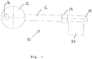
- Figs. 1 - 5 show a lever key blank 10 of a conventional configuration which is not according to the invention.
- the lever key blank 10 includes a flat circular head 12 with a through hole 14 for mounting on a keyring or elsewhere.
- a circular cross-section shank 16 extends from the head 12.
- the blade 20 is a square sheet of material parallel to the head 12, and will in practice be cut to a required formation to operate a particular lock.
- the shank 16 extends for just a short distance beyond the blade 20 and has a frusto conical end 22.
- the blade 20 would be cut manually or in a machine to a required formation, and can be used to lock or unlock a particular lock mechanism, with the collar 18 generally acting as an abutment to ensure the blade 20 enters the lock mechanism to a required depth.
- lever key blanks 10 may be provided in a stack 24 one on top of each, generally with the heads 12 and blades 20 parallel to each other, and such stacks 24 may be provided in a cartridge or other receptacle.
- Fig. 5 indicates a typical problem with such a stack 24 in that the collars 18 are the widest part of the blank 10 in this orientation, and the blanks 10 tend to pivot about the collars 18 such that the uppermost blank 10 is pivotted at a significant inclination relative to the lowermost blank 10. In practice this can lead to jamming of the blanks 10 in a magazine, cartridge or elsewhere, and/or difficulties in mechanical handling of such blanks 10.
- Figs. 6 - 10 show a first lever key blank 26 according to the invention which is similar to the blank 10 except that in this instance two flat stacking formations are provided on the collar 28 in the form of two flat spaced engagement faces 30 which are parallel to the heads 32 and blades 34. As can be seen the distance between the two flat faces 30 is the same as the diameter of the shank 36.
- the engagement faces 30 could extend for around 4mm along the blank 26, and the diameter of the collar 28 excepting the engagement faces 30, is around 7mm. This means that when the blanks 26 are provided in a stack 38, for instance in a magazine or cartridge in a key cutting machine or similar, the blanks 26 will align in a parallel alignment as shown in Fig. 10 .
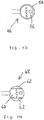
- Figs. 11 and 12 show a third key blank 40.
- the stacking formations are provided in the key blank head 42, in that the key blank head 42 is of increased thickness such that the thickness of the head 42 is equal to the other part of the key blank 40 of greatest thickness, which is the collar 44.
- the collar 44 may also have flat parallel engagement faces, or could be provided with a conventional cylindrical profile.
- the key blanks 40 form a stack of parallel blanks by virtue of the thickness and parallel sides of the head 42.
- Figs. 13 to 17 show the heads respectively of third, fourth, fifth, sixth and seventh key blanks 46, 48, 50, 52, 54, where only part of the key blank head is of increased thickness but will provide the stacking effect as shown in Fig. 11 .
- the key blank head 56 of the third blank 46 shown in Fig. 13 has a raised rim 58 of increased thickness.
- the key blank head 60 shown in Fig. 14 of the fourth key blank 48 has raised portions 62 either side of the key blank head 60.
- the key blank head 64 of the fifth key blank 50 shown in Fig. 15 has a raised portion 66 adjacent to the shank to provide the increased thickness.
- the key blank head 68 of the sixth key blank 52 shown in Fig. 16 has a raised band 70 extending transversely across the head, which band 70 could for instance show the logo and/or name of the key blank maufacturer or supplier.
- a raised rim 74 is shown around a conventional hole 76 provided in the key blank 72 head for mounting a key on a key ring or otherwise.
- the distance between the blanks could be greater than the diameter of the shank.
- stacking formations could be provided elsewhere on a lever key blank, such as along the shank. Providing the distance between the stacking formations the same as the shank diameter is though advantageous in readily providing a stack.
- the weight of keys in the stack will urge them to a parallel alignment as shown for instance in Fig. 11 .
- the shank may not be cylindrical, for example a shank with a pentagonal longitudinal cross section could be provided.
- the collar of the lever key could extend around a part, the majority, or the whole of the longitudinal cross section of the shank.
Landscapes
- Making Paper Articles (AREA)
- Stackable Containers (AREA)
Abstract
Description
- This invention concerns lever key blanks and particularly lever key blanks for use in a key cutting machine, a plurality of lever key blanks, a stack of lever key blanks, and also a key cutting machine.
- In for instance key cutting machines it is generally necessary to locate a stack of similar lever key blanks in a magazine, cartridge or elsewhere. With cylinder keys this is generally quite straightforward as such blanks are generally cut from a sheet material.
- With lever keys though it is often problematic to provide a stack of blanks, as the blanks in the stack will tend not to lie flat on each other, and the blanks in a stack will often end up, and especially at the upper end of the stack, being inclined relative to the blanks at the lower end of the stack. The generally cylindrical profile of the shanks and collars of these key blanks also results in the blanks sliding past one another when stacked. This can prove problematic, with blanks becoming jammed for instance in a magazine, cartridge or elsewhere, and can lead to difficulties in handling the lever key blanks, and particularly mechanically.
- Lever keys generally include a head, which is usually flat. A shank, which is usually cylindrical but may in some instances have a non-circular (e.g. polygonal) longitudinal cross section, extends from the head. A cylindrical shank provides the advantage of a smooth rotational support surface whilst the key is turning in a lock, whereas a shank with for instance a rectangular longitudinal cross-section may catch in the lock whilst turning. A cylindrical profile also results in a stronger shank and is therefore less prone to deformation.
- Spaced along the shank is usually a collar which is often cylindrical, but may be frusto conical, and of greater diameter than the remainder of the shank. The collar serves to locate the lever key at a required depth in a lock. A collar which extends around the whole (e.g. cylindrical) or majority of the longitudinal cross section of the shank provides a larger, and therefore more stable abutment surface.
- A blade is usually provided beyond the collar, which blade is again generally flat and usually parallel to the head. The blade is cut so as to activate a particular lock.
- According to a first aspect of the invention there is provided a lever key blank, the blank including stacking formations defining a spaced pair of parallel engagement surfaces which in a direction perpendicular to the surfaces extend beyond or at least as far, as the remainder of lever key blank in that direction.
- The lever key blank may include a shank, and the longitudinal cross section of at least the majority of the shank may be non-rectangular. A portion of the longitudinal cross section of at least the majority of the shank may be rounded. At least the majority of the shank may be cylindrical.
- The lever key blank may include a collar, and the collar may extend around at least the majority of the longitudinal cross section of the shank.
- The stacking formations may comprise a pair of parallel flat engagement surfaces. Stacking formations may be provided on the collar of the lever key blank.
- The stacking formations may extend for the whole length of the collar. The stacking formations may be in the form of chords relative to the remainder of the circular cross-section of the collar.
- The stacking formations may extend for greater than 2mm along the length of the lever key blank.
- The distance between the stacking formation engagement surfaces may be the same as the shank diameter of the lever key blank.
- The stacking formations may be parallel to the head and/or blade of the lever key blank.
- In a further embodiment the stacking formations may be provided on the head of the lever key blank.
- The stacking formations may be in the form of engagement parts of the key blank head being of a thickness at least equal to the maximum thickness of the remainder of the key blank parallel to the key blank head.
the engagement part of the key blank head may be any of: - a raised rim around the key blank head;
- raised strips on either side of the key blank head;
- a raised portion adjacent the key blank shank;
- a raised portion extending across the key blank head; or
- a raised rim around an opening in the key blank head.
- Alternatively the whole of the key blank head may be of a thickness at least equal to the maximum thickness of the remainder of the key blank parallel to the key blank head, and may be of greater thickness than the remainder of the key blank.
- The engagement part of the key blank head may be of greater thickness than the maximum thickness of the remainder of the key blank parallel to the key blank head.
- In a still further embodiment the stacking formations may be provided on the shank of the lever key blank.
- A still further aspect of the invention provides a plurality of lever key blanks for use in key cutting, the lever key blanks being according to any of the preceding fourteen paragraphs.
- The invention further provides a stack of lever key blanks in a receptacle, the lever key blanks being according to any of said preceding fourteen paragraphs.
- A yet further aspect of the invention provides a key cutting machine including a plurality of stacks of lever key blanks according to any of said preceding fourteen paragraphs in receptacles, with identical lever key blanks in each stack, and stacks of different lever key blanks.
- Embodiments of the present invention will now be described by way of example and with reference to the accompanying drawings, in which:-
-
Fig. 1 is a diagrammatic plan view of a conventional lever key blank not according to the invention; -
Fig. 2 is a diagrammatic side view of the lever key blank ofFig. 1 ; -
Fig. 3 is a diagrammatic end view of the lever key blank ofFig. 1 ; -
Fig. 4 is a diagrammatic perspective view of the lever key blank ofFig. 1 ; -
Fig. 5 is a diagrammatic stack of lever key blanks similar to the lever key blank ofFig. 1 ; -
Figs. 6 - 10 are corresponding views toFigs. 1 - 5 , but of a first lever key blank and a stack of first lever key blanks according to the invention; -
Fig. 11 is a similar view toFig. 10 but of a second lever key blank according to the invention; -
Fig. 12 is a diagrammatic plan view of the head of the second key blank ofFig. 11 ; and -
Figs. 13 - 17 are similar views toFig. 12 but respectively of third, fourth, fifth, sixth and seventh key blanks according to the invention. -
Figs. 1 - 5 show a lever key blank 10 of a conventional configuration which is not according to the invention. The lever key blank 10 includes a flatcircular head 12 with a throughhole 14 for mounting on a keyring or elsewhere. Acircular cross-section shank 16 extends from thehead 12. Towards the end of theshank 16 away from thekey head 12, acylindrical collar 18 of greater diameter is provided. On theshank 16 beyond thecollar 18 from thehead 12, ablade 20 is provided. Theblade 20 is a square sheet of material parallel to thehead 12, and will in practice be cut to a required formation to operate a particular lock. Theshank 16 extends for just a short distance beyond theblade 20 and has a frustoconical end 22. - As indicated, in use the
blade 20 would be cut manually or in a machine to a required formation, and can be used to lock or unlock a particular lock mechanism, with thecollar 18 generally acting as an abutment to ensure theblade 20 enters the lock mechanism to a required depth. - As noted, and particularly for instance in a key cutting machine, it may be required to provide a plurality of such
lever key blanks 10 in a stack 24 one on top of each, generally with theheads 12 andblades 20 parallel to each other, and such stacks 24 may be provided in a cartridge or other receptacle. -
Fig. 5 indicates a typical problem with such a stack 24 in that thecollars 18 are the widest part of the blank 10 in this orientation, and theblanks 10 tend to pivot about thecollars 18 such that the uppermost blank 10 is pivotted at a significant inclination relative to the lowermost blank 10. In practice this can lead to jamming of theblanks 10 in a magazine, cartridge or elsewhere, and/or difficulties in mechanical handling ofsuch blanks 10. -
Figs. 6 - 10 show a first lever key blank 26 according to the invention which is similar to the blank 10 except that in this instance two flat stacking formations are provided on thecollar 28 in the form of two flat spaced engagement faces 30 which are parallel to theheads 32 andblades 34. As can be seen the distance between the twoflat faces 30 is the same as the diameter of theshank 36. - Typically the
engagement faces 30 could extend for around 4mm along the blank 26, and the diameter of thecollar 28 excepting the engagement faces 30, is around 7mm. This means that when theblanks 26 are provided in a stack 38, for instance in a magazine or cartridge in a key cutting machine or similar, theblanks 26 will align in a parallel alignment as shown inFig. 10 . - Therefore this relatively small change from a conventional lever key blank, which may otherwise be difficult to stack, provides significant advantages, making such blanks able to be readily and reliably used for instance in a key cutting machine and other applications.
-
Figs. 11 and 12 show a third key blank 40. In this instance the stacking formations are provided in the keyblank head 42, in that the keyblank head 42 is of increased thickness such that the thickness of thehead 42 is equal to the other part of the key blank 40 of greatest thickness, which is thecollar 44. In this instance thecollar 44 may also have flat parallel engagement faces, or could be provided with a conventional cylindrical profile. As can be seen inFig. 11 , thekey blanks 40 form a stack of parallel blanks by virtue of the thickness and parallel sides of thehead 42. -
Figs. 13 to 17 show the heads respectively of third, fourth, fifth, sixth and seventhkey blanks Fig. 11 . - The key
blank head 56 of the third blank 46 shown inFig. 13 has a raisedrim 58 of increased thickness. The keyblank head 60 shown inFig. 14 of the fourth key blank 48 has raisedportions 62 either side of the keyblank head 60. - The key blank head 64 of the fifth key blank 50 shown in
Fig. 15 , has a raisedportion 66 adjacent to the shank to provide the increased thickness. The keyblank head 68 of the sixth key blank 52 shown inFig. 16 , has a raisedband 70 extending transversely across the head, which band 70 could for instance show the logo and/or name of the key blank maufacturer or supplier. - In the key
blank head 72 of the seventh key blank 54 shown inFig. 17 , a raisedrim 74 is shown around aconventional hole 76 provided in the key blank 72 head for mounting a key on a key ring or otherwise. - It is to be realised that a number of other modifications may be made without departing from the scope of the invention. For instance the distance between the blanks could be greater than the diameter of the shank. In some instances stacking formations could be provided elsewhere on a lever key blank, such as along the shank. Providing the distance between the stacking formations the same as the shank diameter is though advantageous in readily providing a stack. In practice though with a stack of blanks where the distance is greater than the shank diameter, the weight of keys in the stack will urge them to a parallel alignment as shown for instance in
Fig. 11 . In some instances, the shank may not be cylindrical, for example a shank with a pentagonal longitudinal cross section could be provided. The collar of the lever key could extend around a part, the majority, or the whole of the longitudinal cross section of the shank. - Whilst endeavouring in the foregoing specification to draw attention to those features of the invention believed to be of particular importance it should be understood that the Applicant claims protection in respect of any patentable feature or combination of features hereinbefore referred to and/or shown in the drawings whether or not particular emphasis has been placed thereon.
Claims (15)
- A lever key blank, the blank including stacking formations defining a spaced pair of parallel engagement surfaces which in a direction perpendicular to the surfaces extend beyond or at least as far, as the remainder of the lever key blank in that direction.
- A lever key blank according to claim 1, in which the lever key blank includes a shank.
- A lever key blank according to claim 2, in which the longitudinal cross section of at least the majority of the shank is non-rectangular.
- A lever key blank according to claims 2 or 3, in which a portion of the longitudinal cross section of at least the majority of the shank is rounded.
- A lever key blank according to claim 2, in which at least the majority of the shank is substantially cylindrical.
- A lever key blank according to any of the preceding claims, in which the lever key blank includes a collar.
- A lever key blank according to claim 6, in which the collar extends around at least the majority of the longitudinal cross section of the shank.
- A lever key blank according to any of the preceding claims, in which the stacking formations comprise a pair of parallel flat engagement surfaces.
- A lever key blank according to any of claims 6 to 8, in which stacking formations are provided on the collar of the lever key blank.
- A lever key blank according to claim 9, in which the stacking formations are in the form of chords relative to the remainder of the circular cross-section of the collar.
- A lever key blank according to any of claims 1 to 8, in which the stacking formations are provided on the head of the lever key blank.
- A lever key blank according to any of claims 2 to 8, in which the stacking formations are provided on the shank of the lever key blank.
- A plurality of lever key blanks for use in key cutting, the lever key blanks being according to any of the preceding claims.
- A stack of lever key blanks in a receptacle, the lever key blanks being according to any of claims 1 to 12.
- A key cutting machine including a plurality of stacks of lever key blanks according to any of claims 1 to 12 in receptacles, with identical lever key blanks in each stack, and stacks of different lever key blanks.
Applications Claiming Priority (1)
| Application Number | Priority Date | Filing Date | Title |
|---|---|---|---|
| GBGB1706448.6A GB201706448D0 (en) | 2017-04-24 | 2017-04-24 | Keys |
Publications (3)
| Publication Number | Publication Date |
|---|---|
| EP3396085A1 true EP3396085A1 (en) | 2018-10-31 |
| EP3396085B1 EP3396085B1 (en) | 2025-09-24 |
| EP3396085C0 EP3396085C0 (en) | 2025-09-24 |
Family
ID=58795793
Family Applications (1)
| Application Number | Title | Priority Date | Filing Date |
|---|---|---|---|
| EP18168334.3A Active EP3396085B1 (en) | 2017-04-24 | 2018-04-19 | Keys |
Country Status (2)
| Country | Link |
|---|---|
| EP (1) | EP3396085B1 (en) |
| GB (2) | GB201706448D0 (en) |
Citations (5)
| Publication number | Priority date | Publication date | Assignee | Title |
|---|---|---|---|---|
| US103837A (en) * | 1870-06-07 | Improvement in door-keys | ||
| GB167303A (en) * | 1920-05-08 | 1921-08-08 | Gerald Albert Phillips | Improvements in keys for lever locks |
| DE8615345U1 (en) * | 1986-06-06 | 1986-07-31 | Burg-Wächter KG Alfred Lüling, 5882 Meinerzhagen | key |
| WO2005085567A1 (en) * | 2004-03-04 | 2005-09-15 | Assa Abloy Limited | Keys |
| DE202009001921U1 (en) * | 2009-02-27 | 2010-07-22 | Schulte-Schlagbaum Aktiengesellschaft | Room door lock |
Family Cites Families (6)
| Publication number | Priority date | Publication date | Assignee | Title |
|---|---|---|---|---|
| US160660A (en) * | 1875-03-09 | Improvement in folding-door keys | ||
| GB288923A (en) * | 1927-11-14 | 1928-04-19 | Friedrich Wilhelm Moenninghoff | Improvements in or relating to blocks for attachment to keys |
| GB806773A (en) * | 1956-05-10 | 1958-12-31 | Scipione Roger Manzardo | Improvements in or relating to identification means for application to the handle ofa key or similar object |
| GB854868A (en) * | 1958-09-30 | 1960-11-23 | Yale & Towne Mfg Co | Keys for locks |
| GB1492552A (en) * | 1975-11-07 | 1977-11-23 | Evered Security Prod Ltd | Mortice locks and keys and key blanks therefor |
| US20020134122A1 (en) * | 2001-03-26 | 2002-09-26 | Chi-Yuan Li | Cylinder-pushing type of lock device |
-
2017
- 2017-04-24 GB GBGB1706448.6A patent/GB201706448D0/en not_active Ceased
-
2018
- 2018-04-19 GB GB1806414.7A patent/GB2563488B/en active Active
- 2018-04-19 EP EP18168334.3A patent/EP3396085B1/en active Active
Patent Citations (5)
| Publication number | Priority date | Publication date | Assignee | Title |
|---|---|---|---|---|
| US103837A (en) * | 1870-06-07 | Improvement in door-keys | ||
| GB167303A (en) * | 1920-05-08 | 1921-08-08 | Gerald Albert Phillips | Improvements in keys for lever locks |
| DE8615345U1 (en) * | 1986-06-06 | 1986-07-31 | Burg-Wächter KG Alfred Lüling, 5882 Meinerzhagen | key |
| WO2005085567A1 (en) * | 2004-03-04 | 2005-09-15 | Assa Abloy Limited | Keys |
| DE202009001921U1 (en) * | 2009-02-27 | 2010-07-22 | Schulte-Schlagbaum Aktiengesellschaft | Room door lock |
Also Published As
| Publication number | Publication date |
|---|---|
| EP3396085B1 (en) | 2025-09-24 |
| GB2563488A (en) | 2018-12-19 |
| GB201806414D0 (en) | 2018-06-06 |
| GB201706448D0 (en) | 2017-06-07 |
| EP3396085C0 (en) | 2025-09-24 |
| GB2563488B (en) | 2022-08-31 |
Similar Documents
| Publication | Publication Date | Title |
|---|---|---|
| EP2523771B1 (en) | Hole cutter with axially- elongated aperture defining multiple fulcrums | |
| US6588992B2 (en) | Hole saw | |
| US20200061721A1 (en) | Hole saw | |
| US8579554B2 (en) | Hole cutter with axially-elongated aperture defining multiple fulcrums | |
| US12589443B2 (en) | Hole cutter with multiple fulcrums | |
| US8328476B2 (en) | Quick change arbor, hole cutter, and method | |
| US20100310332A1 (en) | Quick core removal hole cutting product | |
| EP2091703B1 (en) | Saw, handle and blade | |
| US20090142152A1 (en) | Reinforcement drill | |
| EP3396085B1 (en) | Keys | |
| US7544022B2 (en) | Milling cutter | |
| US8631550B2 (en) | Tool for attaching/removing a mower blade cutting insert | |
| US20150209866A1 (en) | Disposable multi-edge carving blade | |
| US10974410B2 (en) | Stripper clip | |
| EP1769869B1 (en) | Hole cutter | |
| KR102147116B1 (en) | Hole cutter | |
| US11613031B2 (en) | Utility knife | |
| US9469044B2 (en) | Router attachment assembly | |
| EP2902143A1 (en) | Disposable multi-edge carving blade | |
| US20060288829A1 (en) | Hardened Utility Knife, With Optional Nail Set and Pry Bar | |
| WO2005085567A1 (en) | Keys | |
| EP1808247A1 (en) | Milling cutter |
Legal Events
| Date | Code | Title | Description |
|---|---|---|---|
| PUAI | Public reference made under article 153(3) epc to a published international application that has entered the european phase |
Free format text: ORIGINAL CODE: 0009012 |
|
| STAA | Information on the status of an ep patent application or granted ep patent |
Free format text: STATUS: THE APPLICATION HAS BEEN PUBLISHED |
|
| AK | Designated contracting states |
Kind code of ref document: A1 Designated state(s): AL AT BE BG CH CY CZ DE DK EE ES FI FR GB GR HR HU IE IS IT LI LT LU LV MC MK MT NL NO PL PT RO RS SE SI SK SM TR |
|
| AX | Request for extension of the european patent |
Extension state: BA ME |
|
| STAA | Information on the status of an ep patent application or granted ep patent |
Free format text: STATUS: REQUEST FOR EXAMINATION WAS MADE |
|
| 17P | Request for examination filed |
Effective date: 20190424 |
|
| RBV | Designated contracting states (corrected) |
Designated state(s): AL AT BE BG CH CY CZ DE DK EE ES FI FR GB GR HR HU IE IS IT LI LT LU LV MC MK MT NL NO PL PT RO RS SE SI SK SM TR |
|
| STAA | Information on the status of an ep patent application or granted ep patent |
Free format text: STATUS: EXAMINATION IS IN PROGRESS |
|
| 17Q | First examination report despatched |
Effective date: 20211124 |
|
| RAP3 | Party data changed (applicant data changed or rights of an application transferred) |
Owner name: ICONX INTERNATIONAL LIMITED |
|
| GRAP | Despatch of communication of intention to grant a patent |
Free format text: ORIGINAL CODE: EPIDOSNIGR1 |
|
| STAA | Information on the status of an ep patent application or granted ep patent |
Free format text: STATUS: GRANT OF PATENT IS INTENDED |
|
| INTG | Intention to grant announced |
Effective date: 20250422 |
|
| GRAS | Grant fee paid |
Free format text: ORIGINAL CODE: EPIDOSNIGR3 |
|
| GRAA | (expected) grant |
Free format text: ORIGINAL CODE: 0009210 |
|
| STAA | Information on the status of an ep patent application or granted ep patent |
Free format text: STATUS: THE PATENT HAS BEEN GRANTED |
|
| AK | Designated contracting states |
Kind code of ref document: B1 Designated state(s): AL AT BE BG CH CY CZ DE DK EE ES FI FR GB GR HR HU IE IS IT LI LT LU LV MC MK MT NL NO PL PT RO RS SE SI SK SM TR |
|
| REG | Reference to a national code |
Ref country code: GB Ref legal event code: FG4D |
|
| REG | Reference to a national code |
Ref country code: CH Ref legal event code: EP |
|
| REG | Reference to a national code |
Ref country code: DE Ref legal event code: R096 Ref document number: 602018085802 Country of ref document: DE |
|
| REG | Reference to a national code |
Ref country code: IE Ref legal event code: FG4D |
|
| U01 | Request for unitary effect filed |
Effective date: 20251009 |
|
| U07 | Unitary effect registered |
Designated state(s): AT BE BG DE DK EE FI FR IT LT LU LV MT NL PT RO SE SI Effective date: 20251020 |
|
| PG25 | Lapsed in a contracting state [announced via postgrant information from national office to epo] |
Ref country code: NO Free format text: LAPSE BECAUSE OF FAILURE TO SUBMIT A TRANSLATION OF THE DESCRIPTION OR TO PAY THE FEE WITHIN THE PRESCRIBED TIME-LIMIT Effective date: 20251224 |
|
| PG25 | Lapsed in a contracting state [announced via postgrant information from national office to epo] |
Ref country code: HR Free format text: LAPSE BECAUSE OF FAILURE TO SUBMIT A TRANSLATION OF THE DESCRIPTION OR TO PAY THE FEE WITHIN THE PRESCRIBED TIME-LIMIT Effective date: 20250924 |
|
| PG25 | Lapsed in a contracting state [announced via postgrant information from national office to epo] |
Ref country code: GR Free format text: LAPSE BECAUSE OF FAILURE TO SUBMIT A TRANSLATION OF THE DESCRIPTION OR TO PAY THE FEE WITHIN THE PRESCRIBED TIME-LIMIT Effective date: 20251225 |
|
| PG25 | Lapsed in a contracting state [announced via postgrant information from national office to epo] |
Ref country code: RS Free format text: LAPSE BECAUSE OF FAILURE TO SUBMIT A TRANSLATION OF THE DESCRIPTION OR TO PAY THE FEE WITHIN THE PRESCRIBED TIME-LIMIT Effective date: 20251224 |
|
| PG25 | Lapsed in a contracting state [announced via postgrant information from national office to epo] |
Ref country code: SM Free format text: LAPSE BECAUSE OF FAILURE TO SUBMIT A TRANSLATION OF THE DESCRIPTION OR TO PAY THE FEE WITHIN THE PRESCRIBED TIME-LIMIT Effective date: 20250924 |
|
| PG25 | Lapsed in a contracting state [announced via postgrant information from national office to epo] |
Ref country code: ES Free format text: LAPSE BECAUSE OF FAILURE TO SUBMIT A TRANSLATION OF THE DESCRIPTION OR TO PAY THE FEE WITHIN THE PRESCRIBED TIME-LIMIT Effective date: 20250924 |
|
| PG25 | Lapsed in a contracting state [announced via postgrant information from national office to epo] |
Ref country code: IS Free format text: LAPSE BECAUSE OF FAILURE TO SUBMIT A TRANSLATION OF THE DESCRIPTION OR TO PAY THE FEE WITHIN THE PRESCRIBED TIME-LIMIT Effective date: 20260124 |
|
| PG25 | Lapsed in a contracting state [announced via postgrant information from national office to epo] |
Ref country code: CZ Free format text: LAPSE BECAUSE OF FAILURE TO SUBMIT A TRANSLATION OF THE DESCRIPTION OR TO PAY THE FEE WITHIN THE PRESCRIBED TIME-LIMIT Effective date: 20250924 |
|
| PG25 | Lapsed in a contracting state [announced via postgrant information from national office to epo] |
Ref country code: PL Free format text: LAPSE BECAUSE OF FAILURE TO SUBMIT A TRANSLATION OF THE DESCRIPTION OR TO PAY THE FEE WITHIN THE PRESCRIBED TIME-LIMIT Effective date: 20250924 |
|
| PG25 | Lapsed in a contracting state [announced via postgrant information from national office to epo] |
Ref country code: SK Free format text: LAPSE BECAUSE OF FAILURE TO SUBMIT A TRANSLATION OF THE DESCRIPTION OR TO PAY THE FEE WITHIN THE PRESCRIBED TIME-LIMIT Effective date: 20250924 |