EP2091703B1 - Saw, handle and blade - Google Patents
Saw, handle and blade Download PDFInfo
- Publication number
- EP2091703B1 EP2091703B1 EP07852245.5A EP07852245A EP2091703B1 EP 2091703 B1 EP2091703 B1 EP 2091703B1 EP 07852245 A EP07852245 A EP 07852245A EP 2091703 B1 EP2091703 B1 EP 2091703B1
- Authority
- EP
- European Patent Office
- Prior art keywords
- blade
- handle
- insert
- fastening device
- rotational body
- Prior art date
- Legal status (The legal status is an assumption and is not a legal conclusion. Google has not performed a legal analysis and makes no representation as to the accuracy of the status listed.)
- Active
Links
- 230000015572 biosynthetic process Effects 0.000 claims description 8
- 230000003247 decreasing effect Effects 0.000 claims description 5
- 230000000087 stabilizing effect Effects 0.000 claims 2
- 210000002105 tongue Anatomy 0.000 description 21
- 238000010276 construction Methods 0.000 description 2
- 230000006870 function Effects 0.000 description 2
- 238000004519 manufacturing process Methods 0.000 description 2
- 238000000034 method Methods 0.000 description 2
- 230000004048 modification Effects 0.000 description 2
- 238000012986 modification Methods 0.000 description 2
- 230000008569 process Effects 0.000 description 2
- 230000000717 retained effect Effects 0.000 description 2
- 230000009471 action Effects 0.000 description 1
- 230000007423 decrease Effects 0.000 description 1
- 230000001419 dependent effect Effects 0.000 description 1
- 230000014509 gene expression Effects 0.000 description 1
- 230000008571 general function Effects 0.000 description 1
- 239000003292 glue Substances 0.000 description 1
- 230000014759 maintenance of location Effects 0.000 description 1
- 239000000463 material Substances 0.000 description 1
- 230000007246 mechanism Effects 0.000 description 1
- 239000002184 metal Substances 0.000 description 1
- 230000002093 peripheral effect Effects 0.000 description 1
Images


Classifications
-
- B—PERFORMING OPERATIONS; TRANSPORTING
- B27—WORKING OR PRESERVING WOOD OR SIMILAR MATERIAL; NAILING OR STAPLING MACHINES IN GENERAL
- B27B—SAWS FOR WOOD OR SIMILAR MATERIAL; COMPONENTS OR ACCESSORIES THEREFOR
- B27B21/00—Hand saws without power drive; Equipment for hand sawing, e.g. saw horses
-
- B—PERFORMING OPERATIONS; TRANSPORTING
- B27—WORKING OR PRESERVING WOOD OR SIMILAR MATERIAL; NAILING OR STAPLING MACHINES IN GENERAL
- B27B—SAWS FOR WOOD OR SIMILAR MATERIAL; COMPONENTS OR ACCESSORIES THEREFOR
- B27B21/00—Hand saws without power drive; Equipment for hand sawing, e.g. saw horses
- B27B21/04—Cross-cut saws; Pad saws
-
- B—PERFORMING OPERATIONS; TRANSPORTING
- B23—MACHINE TOOLS; METAL-WORKING NOT OTHERWISE PROVIDED FOR
- B23D—PLANING; SLOTTING; SHEARING; BROACHING; SAWING; FILING; SCRAPING; LIKE OPERATIONS FOR WORKING METAL BY REMOVING MATERIAL, NOT OTHERWISE PROVIDED FOR
- B23D51/00—Sawing machines or sawing devices working with straight blades, characterised only by constructional features of particular parts; Carrying or attaching means for tools, covered by this subclass, which are connected to a carrier at both ends
- B23D51/08—Sawing machines or sawing devices working with straight blades, characterised only by constructional features of particular parts; Carrying or attaching means for tools, covered by this subclass, which are connected to a carrier at both ends of devices for mounting straight saw blades or other tools
- B23D51/10—Sawing machines or sawing devices working with straight blades, characterised only by constructional features of particular parts; Carrying or attaching means for tools, covered by this subclass, which are connected to a carrier at both ends of devices for mounting straight saw blades or other tools for hand-held or hand-operated devices
-
- B—PERFORMING OPERATIONS; TRANSPORTING
- B23—MACHINE TOOLS; METAL-WORKING NOT OTHERWISE PROVIDED FOR
- B23D—PLANING; SLOTTING; SHEARING; BROACHING; SAWING; FILING; SCRAPING; LIKE OPERATIONS FOR WORKING METAL BY REMOVING MATERIAL, NOT OTHERWISE PROVIDED FOR
- B23D61/00—Tools for sawing machines or sawing devices; Clamping devices for these tools
- B23D61/12—Straight saw blades; Strap saw blades
- B23D61/123—Details of saw blade body
-
- B—PERFORMING OPERATIONS; TRANSPORTING
- B27—WORKING OR PRESERVING WOOD OR SIMILAR MATERIAL; NAILING OR STAPLING MACHINES IN GENERAL
- B27B—SAWS FOR WOOD OR SIMILAR MATERIAL; COMPONENTS OR ACCESSORIES THEREFOR
- B27B33/00—Sawing tools for saw mills, sawing machines, or sawing devices
- B27B33/02—Structural design of saw blades or saw teeth
- B27B33/10—Hand saw blades
Definitions
- the present invention relates to a saw according to the preamble of claim 1 and comprising at least one handle and at least one blade, the handle having at least one fastening device having at least one first part in the form of a rotational body, which rotational body can be turned around a first turning axis, the blade being detachable from the handle and having at least one through cut out extending from an edge of the blade.
- the present invention also relates to a handle according to the preamble of claim 6 for use in a saw and a blade according to the preamble of claim 11 for use in a saw.
- Such a saw according to the preamble of claim 1 and such a handle according to the preamble of claim 6 are known from US2140496A1 .
- US, A, 1 405 925 shows a saw handle having a detachable blade.
- the combination allows the use of a number of blades for the same handle, including blades of different types for different kinds of work.
- blades of different thickness cannot be used and the stability upon sawing is not at optimum.
- U1 also discloses a saw handle according to the preamble of claim 11 and having a detachable blade.
- This saw handle discloses a spring locking lever mechanism for releasing the detachable blade.
- a first object of the present invention is to provide a saw that, in spite of the blade being detachable, holds the blade more firmly and is more stable upon sawing than hitherto known saws of the corresponding type.
- a second object of the present invention is to provide a handle for use in such a saw.
- a third object of the present invention is to provide a blade for use in such a saw.
- a fourth object of the present invention is to provide a saw that, by the blade being detachable, allows the fitting of blades of different thicknesses.
- a fifth object of the present invention is to provide a handle for use in such a saw.
- a sixth object of the present invention is to provide a blade for use in such a saw.
- a seventh object of the present invention is to provide a saw that, by the blade being detachable, allows the fitting of blades upside down in the handle.
- An eighth object of the present invention is to provide a handle for use in such a saw.
- a ninth object of the present invention is to provide a blade for use in such a saw.
- a tenth object of the present invention is to provide a saw that, by the handle being ergonomically and/or asymmetrically shaped and the blade being detachable, allows sawing with highest comfort and/or with best control and/or with best sawing performance using different types of blades.
- An eleventh object of the present invention is to provide a handle for use in such a saw.
- a twelfth object of the present invention is to provide a blade for use in such a saw.
- the invention embraces a saw as defined by the features of claim 1.
- the invention also embraces a handle as defined by the features of claim 6.
- the invention also embraces a blade as defined by the features of claim 11.
- FIG. 1-9 it is seen in sequence how a blade 1 according to the invention is being fitted in a handle 2 according to the invention, consequently a saw according to the invention being obtained.
- the blade 1 is equipped with a cut out 3 in the end thereof facing the handle, see Figure 1 .
- the cut out 3 is symmetrically shaped, i.e., an upper half 3a of the cut out 3, such as it is seen in the figure, is a mirror image of a lower half 3b.
- the blade 1 is equipped with two side spring tongues 4a, 4b, which are characterized in that they, each one, have an ability to spring somewhat laterally out from the blade 1, i.e., spring substantially perpendicular to the substantial plane of extension of the blade 1.
- the handle 2 is equipped with a fastening device that, in a first embodiment according to the Figures 1-9 , comprises two plates 5 situated at a distance from each other, a rotational body 6 and a second shaft 7.
- the plates 5 are together somewhat movable in relation to the rest of the handle 2 and also in relation to the rest of the fastening device.
- the rotational body 6 consists of a plurality of co-rotating parts and is operated by an actuation device 8, which via a first shaft 9 is connected to the rest of the rotational body 6.
- the shafts 7, 9 extend substantially perpendicular to the substantial plane of extension of the fastening device, i.e., the substantial plane of extension of the plates 5.
- the shafts 7, 9 also extend through the plates 5, the first shaft 9 being mounted with a play in the form of a circumferential opening in a first end of the respective plate 5 (the upper end of the respective plate 5 such as they are shown in the Figures 1-9 ) and the second shaft 7 is mounted with a play in the form of an elongate recess in a second end of the respective plate 5 (the lower end of the respective plate 5 such as they are shown in the Figures 1-9 ).
- the second shaft 7 present on the handle 2 is placed in the lower half 3b of the cut out 3 in the blade 1, see Figure 2 , and then the blade 1 is turned in the substantial plane of extension thereof until the rotational body 6 reaches the bottom in the upper half 3a of the cut out 3, see Figure 3 .
- a locking phase follows, the rotational body 6 being operated by the actuation device 8 in such a way that the free end of the actuation device 8 is pressed in a continuous motion against the handle 2, see the Figures 4-9 .
- the blade will also be pulled further closer to the handle since a finger-like formation 10 of the rotational body 6 co-operates with the correspondingly shaped upper part 3a of the cut out 3 in the blade 1.
- a bulge 11 and a first stop lip 12 On the rotational body 6, there are also, in the present first embodiment, a bulge 11 and a first stop lip 12.
- the bulge 11 reaches the side spring tongue 4a in the position of the rotational body 6 that corresponds to Figure 5 , presses the side spring tongue 4a out/up and passes under the same in the position of the rotational body 6 that corresponds to the Figures 6-8 , and leaves the side spring tongue 4a in the position of the rotational body 6 that corresponds to Figure 9 , in which position the bulge 11 and the stop lip 12 together lock the side spring tongue 4a and thereby the blade in position in the handle. This locked position is seen more clearly in partial enlargement in Figure 12 .
- the bulge 11 has a length in the peripheral direction (i.e., a direction that is substantially perpendicular to a radius through the first shaft 9, which radius is substantially perpendicular to the substantial direction of extension of the first shaft 9) that approximately corresponds to a distance between the side spring tongue 4a and the rest of the blade 1, i.e., the bulge 11 is accommodated with precision in the space between the side spring tongue 4a and the rest of the blade 1.
- the edges of the bulge 11 against the side spring tongue 4a and the rest of the blade 1 are chamfered.
- the edge of the stop lip 12 facing the side spring tongue 4a is, however, not chamfered in order to give the most stable possible locking.
- One of the plates 5 is equipped with a particular driver 13, which makes that the blade in the locked position presses the plates 5 as close to the handle as possible.
- a disassembly of the blade 2 takes place in an analogous way. Additional force is initially required to overcome the resilient force of the side spring tongue 4a when the bulge 11, by the actuation device 8 being spaced apart from the handle 2, is brought to lift the side spring tongue 4a and pass under the same.
- Figure 10 it is seen how the bulge 11 is positioned precisely under the side spring tongue 4a when the actuation device 8 has been spaced apart from the handle 2 into a position that for the fitting phase corresponds to the position according to Figure 7 .
- Blades 1 may be manufactured with different angles between the substantial direction of extension of the cut out 3 in the plane of the blade and the toothed edge of the blade, which blades become suitable for different fields of application. Also the level/position of the cut out 3 on the blade end may be varied, i.e., the cut out 3 may be placed differently far from the toothed edge of the blade.
- the bulge 11 has been replaced by a second stop lip 12b, the blade 1 in the locked position being entirely locked between the stop lips 12, 12b, see Figure 13 .
- a release bulge 11b is present, radially outside the stop lips 12, 12b, that only is used to first lift the side spring tongue 4a so that after that, a stop lip 12b can pass the side spring tongue 4a when disassembling a blade 1.
- the release bulge 11b is brought in under the side spring tongue 4a and lifts the same, see Figure 14 , after which further lifting of the actuation device 8 also turns the stop lips 12, 12b and the blade 1 is released, see Figure 15 .
- an insert 14 is seen manufactured from one and the same piece of plate, which insert may be used, i.e., originally be fitted by the manufacturer of the tool, in the space between the plates 5 to allow the use of saw blades of different thicknesses in one and the same handle, as well as to further improve the stability in the retention of the blade locked in the handle.
- the insert 14 is manufactured with an inherent initial stress resulting in a first branch 15 always aiming to keep a certain distance to a second branch 16.
- the insert 14 In the branches 15, 16, there are pressed protuberances 17 that, when the insert 14 is placed in the space between the plates 5, contribute to provide a larger pressure than otherwise from other parts of the insert 14 against a blade 1 that is being fitted and/or is fitted between the branches 15, 16.
- the insert 14 is also somewhat movable in relation to the rest of the handle 2 and also in relation to the rest of the fastening device, i.e., also in relation to the plates 5.
- the motion of the insert 14 between the plates 5 takes place around and/or in relation to said first turning axis 6 in said first end of the fastening device and around and/or in relation to said second turning axis 7 in said second end of the fastening device.
- the insert 14 may be present in constructions according to each one of the described first and second embodiments and is, if so, a part of the fastening device.
- the insert 14 may also be present in a construction where the plates 5 are lacking and the insert 14 accordingly is fitted in a groove directly in the handle 2, walls in this groove exerting the pressure on the insert 14 that otherwise is exerted by the plates 5 at assembly and/or disassembly of blades 1 in the handle 2.
- FIG. 17a and 17b a first part 18 of the rotational body 6 according to said first embodiment of the invention is seen.
- a corresponding first part 19 of the rotational body 6 according to said second embodiment of the invention is seen, also a second part 20 of the rotational body 6 being required, see each one of Figures 19a and 19b .
- the way the parts 19, 20 in principle are placed on the first shaft 9 is seen in the exploded view according to Figure 20 , a part of the actuation device 8 also being seen.
- each one of the parts 19 and 20 is represented by a body having, in comparison with the real bodies, a very simplified design.
- Figure 20 relates to said second embodiment - in said first embodiment, the part 20 is accordingly spared and the part 19 is replaced by the part 18 according to the above stated.
- the handle 2 is ergonomically and asymmetrically shaped and has a first gripping part 21 having a substantial direction of extension that forms an angle ("tilt") of 5-20°, preferably 10-15° and most preferably 12,5° in relation to a substantial plane of extension of the blade 1, see Figures 21-24 .
- Said first gripping part 21 is the one that rests in the palm of the hand when the saw/the handle is gripped. Also all possible angles between a substantial plane of extension of the handle 2 and a substantial plane of extension of the blade 1 may be varied in the production of the handle 2 in order to make sawing as efficient and comfortable as possible.
- the handle 2 shown in Figures 21-24 is made for right-handed persons, but the shape may naturally be mirror-inverted in the manufacture to fit left-handed persons. The size in general may also be varied, such as height, width and so on to fit differently large hands.
- the handle 2 in Figures 21-24 has no plates 5 and neither no insert 14, but the blade 1 here has been fitted detachably directly in the handle 2, here it should be pointed out that the handle, where appropriate after modification regarding the attachment of the blade in accordance with what has been described above, can be used in combination with any one of the embodiments mentioned in this description.
- the handle 2 may also be used in combination with fixedly fitted saw blades, by which it is understood permanently fitted saw blades that cannot be dismounted unless the saw is destroyed and/or seriously damaged, wherein design details that intend to facilitate the exchange of blades naturally can be spared and traditional fastening elements of the type screws, bolts, rivets and/or the like be used instead. Glue or the like may also be used.
- a saw comprising at least one handle 2 and at least one blade 1, the blade 1 being permanently fitted in the handle 2, wherein said handle 2 is ergonomically and asymmetrically shaped and has at least one first gripping part 21 having a substantial direction of extension that forms an angle of 5-20°, preferably 10-15° and most preferably 12,5° in relation to a substantial plane of extension of said blade 1.
- the handle 2 has a fastening device for the blade 1, which fastening device comprises a rotational body 6, an actuation device 8, a first insert 31, a second insert 32, a second shaft 7, a positioning pin 33 and a first spring 34.
- the rotational body 6, in turn, comprises an eccentric 35, a washer 36, a shaft 9, a second spring 37 and two bearings 38.
- the blade 1 has three through cut outs 3c, 3d, 3e extending from an edge of the blade, the first cut out having a first recess 3cs having substantially parallel sides, the second cut out having a second recess 3ds having substantially parallel sides, while the third cut out 3e constitutes a third recess 3es.
- the fitting takes place in an analogous way in comparison with the first embodiment of the invention.
- the second shaft 7 of the handle 2 is placed in the second (the lower one in Figure 25 ) cut out 3d in the blade 1, after which the blade 1 is turned in the substantial plane of extension thereof until the eccentric 35 reaches the bottom in the first (the upper one in Figure 25 ) cut out 3c, see also Figure 27 .
- the positioning pin 33 fitted directly to the handle 2 or to the inserts 31, 32 is introduced into the third cut out 3e of the blade 1, and the blade is placed between the two branches of the spring 34.
- a locking phase follows, the rotational body 6 being operated by the actuation device 8 in such a way that the free end of the actuation device 8 is pressed in a continuous motion against the handle 2, involving a turning of the rotational body 6 of at least approx. 90°.
- the blade will also be pulled further closer to the handle since a finger-like formation 10 of the eccentric 35 co-operates with the correspondingly shaped first cut out 3c in the blade 1.
- the finger-like formation 10 rests on the eccentric 35 in the first recess 3cs, the second shaft 7 in the second recess 3ds, and the positioning pin 33 in the third recess 3es.
- the blade 1 also has a side spring tongue 4c.
- a first stop lip 12 and a second stop lip 12b on the eccentric 35 there are, also in the present embodiment, a first stop lip 12 and a second stop lip 12b on the eccentric 35, the side spring tongue 4c in the locked position being entirely locked between the stop lips 12, 12b.
- a release bulge 11b is present on the washer 36, radially outside the stop lips 12, 12b, which release bulge 11b only is used to first lift the side spring tongue 4c so that after that, a stop lip 12b can pass the side spring tongue 4c when disassembling a blade 1.
- the release bulge 11b is brought in under the side spring tongue 4c and lifts the same, after which further lifting of the actuation device 8 also turns the stop lips 12, 12b and the blade 1 is released.
- the second spring 37 may, by the co-operation with a particular rib on the eccentric 35 in the open position of the actuation device 8, contribute to a parking position of the actuation device 8, involving that the blade 1 has to be pulled out of the handle 2 by hand the last bit upon disassembly. In this way, the risk is minimized that the blade 1 in an undesired moment falls freely out of the handle 2.
- the first spring 34 has the general function of exerting a distancing force on the inserts 31, 32 when the same are placed in the handle 2. In this way, the force action from the spring 34 replaces the inherent initial stress that previously has been described in connection with the double-sided insert 14 found in a previously described embodiment of the invention.
- the fastening device When the fastening device is maximally open, i.e., the actuation device 8 entirely open, and no blade 1 is fitted in the handle 2, the distance between the inserts 31, 32 is maximal.
- a blade 1 is being fitted and the actuation device 8 is being closed, i.e., the rotational body 6 is turned in the locking direction, the inserts 31, 32 move further inwards in the handle, their modifiedly conical shape making that the pressure generated by the handle 2 on the inserts 31, 32 increases successively and that thereby the pressure generated by the inserts 31, 32 on the blade 1 increases successively.
- the actuation device 8 has been entirely closed, i.e., the rotational body 6 has been turned maximally, the blade 1 is retained maximally stably and entirely free of play in the handle 2.
- the motion of the inserts 31, 32 in the handle 2 takes place around and/or in relation to said first turning axis 6 in said first end of the fastening device and around and/or in relation to said second turning axis 7 in said second end of the fastening device.
- the thickness of the blade varies between approx. 0,73 mm and approx. 1,15 mm, but is usually approx. 1,0 mm (applies to all embodiments).
- the side spring tongue 4c has a length of approx. 5 mm - approx. 90 mm, preferably approx. 5 mm - approx. 30 mm, and most preferably approx. 21 mm. It has a width of approx. 7 mm - approx. 12 mm, preferably approx. 9 mm - approx. 10 mm, and most preferably approx. 9,7 mm.
- a spring 39 has another design and partly function than the second spring 37 according to preceding embodiment.
- An upper/outer end of the spring 39 affords the actuation device 8, when this is in the closed position, i.e., closest to the handle 2, a snap locking.
- An inner end of the spring 39 affords, like the second spring 37 according to preceding embodiment, the actuation device 8 a parking position by the co-operation with a particular rib on the eccentric 35 in the open position of the actuation device 8, involving that the blade 1 has to be pulled out of the handle 2 by hand the last bit upon disassembly. In this way, the risk is minimized, as mentioned above, that the blade 1 in an undesired moment falls freely out of the handle 2.
- the cut out configuration of the blade 1 is also somewhat altered and is most clearly seen in Figure 39 .
- the blade 1 has three through cut outs 3c, 3d, 3e extending from an edge of the blade, the first cut out 3c having a first recess 3cs having substantially parallel sides, the second cut out 3d having a second recess 3ds having substantially parallel sides, while the third cut out 3e constituting a third recess 3es.
- the placement of the third recess 3es and the area above the same in Figure 39 are, however, somewhat altered in comparison with the preceding embodiment, and therefore, in this case, the third cut out 3e can be regarded as a part of the second cut out 3d.
- a further embodiment of the saw according to the invention is seen.
- a spring 40 has another design and partly function than the spring 39 of preceding embodiment.
- an insert 32, an eccentric 35, a washer 36 and the spring 40 are seen in exploded view, the shown parts being placed in a position in relation to each other that corresponds to the open position of the actuation device 8.
- the parts assembled together with a blade 1 are seen in Figure 40b .
- the cut out configuration of the blade 1 is also somewhat altered.
- the blade 1 has three through cut outs 3c, 3d, 3e extending from an edge of the blade, the first cut out having a first recess 3cs having substantially parallel sides, the second cut out having a second recess 3ds having substantially parallel sides, while the third cut out 3e constituting a third recess 3es.
- the placement of the third recess 3es and the area above the same are, however, somewhat altered in comparison with the preceding embodiment.
- the third cut out 3e can be regarded as a part of the second cut out 3d.
- Figure 41 a modification of the blade according to Figures 40b and 40d is seen, the active part 41 being more convex in the substantial plane of extension of the blade 1 and accordingly affecting the spring 40 more.
- first turning axis 6 extends substantially perpendicular to the substantial plane of extension of the blade 1.
- the blades are of metal and the inserts most often of plastic, but any other expedient known materials are feasible.
- insert inlaysgg
- insert insats
Description
- The present invention relates to a saw according to the preamble of
claim 1 and comprising at least one handle and at least one blade, the handle having at least one fastening device having at least one first part in the form of a rotational body, which rotational body can be turned around a first turning axis, the blade being detachable from the handle and having at least one through cut out extending from an edge of the blade. The present invention also relates to a handle according to the preamble of claim 6 for use in a saw and a blade according to the preamble ofclaim 11 for use in a saw. - Such a saw according to the preamble of
claim 1 and such a handle according to the preamble of claim 6 are known fromUS2140496A1 . -
US, A, 1 405 925 shows a saw handle having a detachable blade. The combination allows the use of a number of blades for the same handle, including blades of different types for different kinds of work. However, blades of different thickness cannot be used and the stability upon sawing is not at optimum. -
DE 20 2005 008 995, U1 also discloses a saw handle according to the preamble ofclaim 11 and having a detachable blade. This saw handle discloses a spring locking lever mechanism for releasing the detachable blade. - A first object of the present invention is to provide a saw that, in spite of the blade being detachable, holds the blade more firmly and is more stable upon sawing than hitherto known saws of the corresponding type. A second object of the present invention is to provide a handle for use in such a saw. A third object of the present invention is to provide a blade for use in such a saw.
- A fourth object of the present invention is to provide a saw that, by the blade being detachable, allows the fitting of blades of different thicknesses. A fifth object of the present invention is to provide a handle for use in such a saw. A sixth object of the present invention is to provide a blade for use in such a saw.
- A seventh object of the present invention is to provide a saw that, by the blade being detachable, allows the fitting of blades upside down in the handle. An eighth object of the present invention is to provide a handle for use in such a saw. A ninth object of the present invention is to provide a blade for use in such a saw.
- A tenth object of the present invention is to provide a saw that, by the handle being ergonomically and/or asymmetrically shaped and the blade being detachable, allows sawing with highest comfort and/or with best control and/or with best sawing performance using different types of blades. An eleventh object of the present invention is to provide a handle for use in such a saw. A twelfth object of the present invention is to provide a blade for use in such a saw.
- Thus, the invention embraces a saw as defined by the features of
claim 1. - The invention also embraces a handle as defined by the features of claim 6.
- The invention also embraces a blade as defined by the features of
claim 11. - Further preferred embodiments are defined by the features of dependent claims 2-5, 7-10 and 12-18.
-
-
Figure 1 shows, in perspective view, a part of a handle and a part of a blade according to the invention before fitting of the blade in the handle. -
Figure 2 shows, in perspective view, the handle and the blade according toFigure 1 when the fitting of the blade has been commenced, the blade being in contact with a shaft. -
Figure 3 shows, in perspective view, the handle and the blade according toFigure 1 when the fitting of the blade has proceeded, the blade being in contact with a shaft as well as a rotational body. -
Figure 4 shows, in perspective view, the handle and the blade according toFigure 1 when the fitting of the blade has proceeded further, the rotational body having been turned a first distance. -
Figure 5 shows, in perspective view, the handle and the blade according toFigure 1 when the fitting of the blade has proceeded further, the rotational body having been turned a second distance. -
Figure 6 shows, in perspective view, the handle and the blade according toFigure 1 when the fitting of the blade has proceeded further, the rotational body having been turned a third distance. -
Figure 7 shows, in perspective view, the handle and the blade according toFigure 1 when the fitting of the blade has proceeded further, the rotational body having been turned a fourth distance. -
Figure 8 shows, in perspective view, the handle and the blade according toFigure 1 when the fitting of the blade has proceeded further, the rotational body having been turned a fifth distance. -
Figure 9 shows, in perspective view, the handle and the blade according toFigure 1 when the fitting of the blade has proceeded further, the rotational body having been turned a sixth distance and the blade being maximally inserted into the handle. -
Figure 10 shows, in perspective view, the handle and the blade according toFigure 1 when disassembly of the blade has been commenced, the rotational body having been turned back a distance corresponding to the position inFigure 7 . -
Figure 11 shows, in perspective view, the handle and the blade according toFigure 1 when the blade is fitted upside down in the handle. -
Figure 12 shows, in perspective view, a detail of the handle and the blade according toFigure 1 when the blade is maximally inserted into the handle. -
Figure 13 shows, in side view, an alternative embodiment of a handle and a part of a blade according to the invention, the blade being maximally inserted into the handle. -
Figure 14 shows, in side view, the handle and the blade according toFigure 13 , the rotational body having been turned back a distance corresponding to the position inFigure 7 . -
Figure 15 shows, in side view, the handle and the blade according toFigure 13 , wherein the rotational body has been turned back maximally and the blade can be removed. -
Figure 16a shows, in perspective view, an insert for a fastening device fitted on a handle according to the invention. -
Figure 16b shows, in perspective view, the insert according toFigure 16a as seen from another angle. -
Figure 17a shows, in perspective view, a first part of a rotational body according to the invention. -
Figure 17b shows, in perspective view, the first part according toFigure 17a as seen from another angle. -
Figure 18a shows, in perspective view, an alternative embodiment of a first part of a rotational body according to the invention. -
Figure 18b shows, in perspective view, the first part according toFigure 18a as seen from another angle. -
Figure 19a shows, in perspective view, a second part of a rotational body according to the invention. -
Figure 19b shows, in perspective view, the second part according toFigure 19a as seen from another angle. -
Figure 20 shows, in perspective view, a part of an actuation device, the first part of the rotational body according toFigure 18a , a first shaft and the second part of the rotational body according toFigure 19a according to the invention, the parts of the rotational body being shown schematically. -
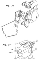
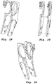
Figure 21 shows, in perspective view obliquely from above, an alternative embodiment of a handle and a part of a blade according to the invention, the blade being fitted in the handle. -
Figure 22 shows, in perspective view obliquely from behind, the handle and the part of the blade according toFigure 21 . -
Figure 23 shows, in perspective view obliquely from below, the handle and the part of the blade according toFigure 21 when the handle is held by a user. -
Figure 24 shows, in side view, the handle and the part of the blade according toFigure 21 when the handle is held by a user who holds the key partly raised. -
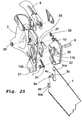
Figure 25 shows, in perspective view from the left and in exploded view, an additional alternative embodiment of a handle and a part of a blade according to the invention and in closed position. -
Figure 26 shows, in perspective view from the right and in exploded view, the handle and the part of the blade according toFigure 25 and in closed position. -
Figure 27 shows, in side view from the right, a part of a rotational body present on the handle according toFigure 25 and in open position. -
Figure 28 shows, in perspective view from the left, two inserts present in the handle according toFigure 25 . -
Figure 29 shows, in perspective view from the left, the inserts according toFigure 28 . -
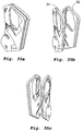
Figure 30 shows, in perspective view from the right, the inserts according toFigure 28 . -
Figure 31 shows, in side view, the blade according toFigure 25 . -
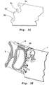
Figure 32 shows, in partly sectioned perspective view from the left, an additional alternative embodiment of a part of a handle (half) and a part of a blade according to the invention and in closed position. -
Figure 33 shows, in partly sectioned perspective view from the left, the part of the handle and the part of the blade according toFigure 32 and in open position. -
Figures 34a and b show, in perspective views, the handle according toFigure 32 and without fastening device. -
Figures 35a, b and c show, in perspective views and in different angles, two inserts present in the handle according toFigure 32 . -
Figure 36 shows, in perspective view from the left and from exploded view, an actuation device present on the handle according toFigure 32 . -
Figures 37a, b and c show, in perspective views and from different angles, parts included in a rotational body present on the handle according toFigure 32 . -
Figure 38 shows, in perspective view from the left, two shafts present on the handle according toFigure 32 . -
Figure 39 shows, in side view, the blade according toFigure 32 and the end of the blade for connection to the handle in partial enlargement. -
Figure 40a shows, in side view and in exploded view, parts of a fastening device included in an additional alternative embodiment of a saw according to the invention, the parts being shown in a position that corresponds to an open position. -
Figure 40b shows, in side view, the parts according toFigure 40a in contact with a blade according to the present embodiment and in open position. -
Figure 40c shows, in side view and in exploded view, the parts according toFigure 40a , the parts being shown in a position that corresponds to the closed position. -
Figure 40d shows, in side view, the parts according toFigure 40a in contact with a blade according to the present embodiment and in closed position. -
Figure 40e shows, in perspective view and in exploded view, the parts according toFigure 40a having a somewhat modified shape and in closed position. -
Figure 41 shows, in side view, the blade according toFigure 40 having a somewhat modified shape. - From the
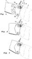
Figures 1-9 , it is seen in sequence how ablade 1 according to the invention is being fitted in ahandle 2 according to the invention, consequently a saw according to the invention being obtained. Theblade 1 is equipped with a cut out 3 in the end thereof facing the handle, seeFigure 1 . The cut out 3 is symmetrically shaped, i.e., anupper half 3a of the cut out 3, such as it is seen in the figure, is a mirror image of alower half 3b. Furthermore, theblade 1 is equipped with twoside spring tongues blade 1, i.e., spring substantially perpendicular to the substantial plane of extension of theblade 1. - The
handle 2 is equipped with a fastening device that, in a first embodiment according to theFigures 1-9 , comprises twoplates 5 situated at a distance from each other, a rotational body 6 and asecond shaft 7. Theplates 5 are together somewhat movable in relation to the rest of thehandle 2 and also in relation to the rest of the fastening device. The rotational body 6 consists of a plurality of co-rotating parts and is operated by anactuation device 8, which via afirst shaft 9 is connected to the rest of the rotational body 6. Theshafts plates 5. Theshafts plates 5, thefirst shaft 9 being mounted with a play in the form of a circumferential opening in a first end of the respective plate 5 (the upper end of therespective plate 5 such as they are shown in theFigures 1-9 ) and thesecond shaft 7 is mounted with a play in the form of an elongate recess in a second end of the respective plate 5 (the lower end of therespective plate 5 such as they are shown in theFigures 1-9 ). - Upon the fitting, first the
second shaft 7 present on thehandle 2 is placed in thelower half 3b of the cut out 3 in theblade 1, seeFigure 2 , and then theblade 1 is turned in the substantial plane of extension thereof until the rotational body 6 reaches the bottom in theupper half 3a of the cut out 3, seeFigure 3 . Next, a locking phase follows, the rotational body 6 being operated by theactuation device 8 in such a way that the free end of theactuation device 8 is pressed in a continuous motion against thehandle 2, see theFigures 4-9 . During this locking process, the blade will also be pulled further closer to the handle since a finger-like formation 10 of the rotational body 6 co-operates with the correspondingly shapedupper part 3a of the cut out 3 in theblade 1. - On the rotational body 6, there are also, in the present first embodiment, a
bulge 11 and afirst stop lip 12. Thebulge 11 reaches theside spring tongue 4a in the position of the rotational body 6 that corresponds toFigure 5 , presses theside spring tongue 4a out/up and passes under the same in the position of the rotational body 6 that corresponds to theFigures 6-8 , and leaves theside spring tongue 4a in the position of the rotational body 6 that corresponds toFigure 9 , in which position thebulge 11 and thestop lip 12 together lock theside spring tongue 4a and thereby the blade in position in the handle. This locked position is seen more clearly in partial enlargement inFigure 12 . Thebulge 11 has a length in the peripheral direction (i.e., a direction that is substantially perpendicular to a radius through thefirst shaft 9, which radius is substantially perpendicular to the substantial direction of extension of the first shaft 9) that approximately corresponds to a distance between theside spring tongue 4a and the rest of theblade 1, i.e., thebulge 11 is accommodated with precision in the space between theside spring tongue 4a and the rest of theblade 1. The edges of thebulge 11 against theside spring tongue 4a and the rest of theblade 1 are chamfered. The edge of thestop lip 12 facing theside spring tongue 4a is, however, not chamfered in order to give the most stable possible locking. One of theplates 5 is equipped with aparticular driver 13, which makes that the blade in the locked position presses theplates 5 as close to the handle as possible. - A disassembly of the
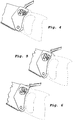
blade 2 takes place in an analogous way. Additional force is initially required to overcome the resilient force of theside spring tongue 4a when thebulge 11, by theactuation device 8 being spaced apart from thehandle 2, is brought to lift theside spring tongue 4a and pass under the same. InFigure 10 , it is seen how thebulge 11 is positioned precisely under theside spring tongue 4a when theactuation device 8 has been spaced apart from thehandle 2 into a position that for the fitting phase corresponds to the position according toFigure 7 . - In
Figure 11 , it is seen how the blade instead has been fitted upside down in the handle, something that is possible by the fact that the cut out 3 has a symmetrical design. A saw having the blade fitted in this way makes sawing upwards toward, for instance, a ceiling, comfortable. -
Blades 1 may be manufactured with different angles between the substantial direction of extension of the cut out 3 in the plane of the blade and the toothed edge of the blade, which blades become suitable for different fields of application. Also the level/position of the cut out 3 on the blade end may be varied, i.e., the cut out 3 may be placed differently far from the toothed edge of the blade. - In a second embodiment of the invention, the
bulge 11 has been replaced by asecond stop lip 12b, theblade 1 in the locked position being entirely locked between thestop lips Figure 13 . In addition to this, arelease bulge 11b is present, radially outside thestop lips side spring tongue 4a so that after that, astop lip 12b can pass theside spring tongue 4a when disassembling ablade 1. By lifting theactuation device 8 approx. 20°, therelease bulge 11b is brought in under theside spring tongue 4a and lifts the same, seeFigure 14 , after which further lifting of theactuation device 8 also turns thestop lips blade 1 is released, seeFigure 15 . - In each one of
Figures 16a and 16b , aninsert 14 is seen manufactured from one and the same piece of plate, which insert may be used, i.e., originally be fitted by the manufacturer of the tool, in the space between theplates 5 to allow the use of saw blades of different thicknesses in one and the same handle, as well as to further improve the stability in the retention of the blade locked in the handle. Theinsert 14 is manufactured with an inherent initial stress resulting in afirst branch 15 always aiming to keep a certain distance to asecond branch 16. In thebranches protuberances 17 that, when theinsert 14 is placed in the space between theplates 5, contribute to provide a larger pressure than otherwise from other parts of theinsert 14 against ablade 1 that is being fitted and/or is fitted between thebranches insert 14 is also somewhat movable in relation to the rest of thehandle 2 and also in relation to the rest of the fastening device, i.e., also in relation to theplates 5. - When the fastening device is maximally open, i.e., the key 8 entirely open, and no
blade 1 is fitted in thehandle 2, the distance between thebranches blade 1 is being fitted and theactuation device 8 is being closed, i.e., the rotational body 6 is turned in the locking direction, theinsert 14 moves further inwards between theplates 5 toward the handle, the pair-wise substantially modifiedly conical shape of the pressedprotuberances 17 making that the pressure generated by theplates 5 on theinsert 14 increases successively, which in turn resulting in the pressure generated by thebranches blade 1 also increasing successively. When theactuation device 8 has been entirely closed, i.e., the rotational body 6 has been turned maximally, theblade 1 is retained maximally stably and entirely free of play in thehandle 2. - When a
blade 1 is being dismounted and theactuation device 8 is being opened, i.e., the rotational body 6 is turned in the unlocking direction, theinsert 14 moves outwards between theplates 5 in the direction from the handle, the pair-wise substantially modifiedly conical shape of the pressedprotuberances 17 making that the pressure generated by theplates 5 on theinsert 14 decreases successively, which in turn resulting in the pressure generated by thebranches blade 1 also decreasing successively. When theactuation device 8 has been opened entirely, i.e., the rotational body 6 has been turned maximally, theblade 1 can be removed from thehandle 2 and the fastening device is maximally open. - The motion of the
insert 14 between theplates 5 takes place around and/or in relation to said first turning axis 6 in said first end of the fastening device and around and/or in relation to saidsecond turning axis 7 in said second end of the fastening device. - The
insert 14 may be present in constructions according to each one of the described first and second embodiments and is, if so, a part of the fastening device. In an example not according to the invention, theinsert 14 may also be present in a construction where theplates 5 are lacking and theinsert 14 accordingly is fitted in a groove directly in thehandle 2, walls in this groove exerting the pressure on theinsert 14 that otherwise is exerted by theplates 5 at assembly and/or disassembly ofblades 1 in thehandle 2. - In each one of
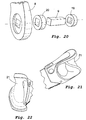
Figures 17a and 17b , afirst part 18 of the rotational body 6 according to said first embodiment of the invention is seen. In each one ofFigures 18a and 18b , a correspondingfirst part 19 of the rotational body 6 according to said second embodiment of the invention is seen, also asecond part 20 of the rotational body 6 being required, see each one ofFigures 19a and 19b . The way theparts first shaft 9 is seen in the exploded view according toFigure 20 , a part of theactuation device 8 also being seen. InFigure 20 , each one of theparts Figure 20 relates to said second embodiment - in said first embodiment, thepart 20 is accordingly spared and thepart 19 is replaced by thepart 18 according to the above stated. - The
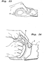
handle 2 is ergonomically and asymmetrically shaped and has a firstgripping part 21 having a substantial direction of extension that forms an angle ("tilt") of 5-20°, preferably 10-15° and most preferably 12,5° in relation to a substantial plane of extension of theblade 1, seeFigures 21-24 . Said first grippingpart 21 is the one that rests in the palm of the hand when the saw/the handle is gripped. Also all possible angles between a substantial plane of extension of thehandle 2 and a substantial plane of extension of theblade 1 may be varied in the production of thehandle 2 in order to make sawing as efficient and comfortable as possible. Thehandle 2 shown inFigures 21-24 is made for right-handed persons, but the shape may naturally be mirror-inverted in the manufacture to fit left-handed persons. The size in general may also be varied, such as height, width and so on to fit differently large hands. - Even if the
handle 2 inFigures 21-24 has noplates 5 and neither noinsert 14, but theblade 1 here has been fitted detachably directly in thehandle 2, here it should be pointed out that the handle, where appropriate after modification regarding the attachment of the blade in accordance with what has been described above, can be used in combination with any one of the embodiments mentioned in this description. Thehandle 2 may also be used in combination with fixedly fitted saw blades, by which it is understood permanently fitted saw blades that cannot be dismounted unless the saw is destroyed and/or seriously damaged, wherein design details that intend to facilitate the exchange of blades naturally can be spared and traditional fastening elements of the type screws, bolts, rivets and/or the like be used instead. Glue or the like may also be used. Thus, it is fully possible to conceive a saw comprising at least onehandle 2 and at least oneblade 1, theblade 1 being permanently fitted in thehandle 2, wherein saidhandle 2 is ergonomically and asymmetrically shaped and has at least one firstgripping part 21 having a substantial direction of extension that forms an angle of 5-20°, preferably 10-15° and most preferably 12,5° in relation to a substantial plane of extension of saidblade 1. - In the
Figures 25-31 , a further embodiment of the saw according to the invention is seen. Thehandle 2 has a fastening device for theblade 1, which fastening device comprises a rotational body 6, anactuation device 8, afirst insert 31, asecond insert 32, asecond shaft 7, apositioning pin 33 and afirst spring 34. The rotational body 6, in turn, comprises an eccentric 35, awasher 36, ashaft 9, asecond spring 37 and twobearings 38. Theblade 1 has three throughcut outs - The fitting takes place in an analogous way in comparison with the first embodiment of the invention. First, the
second shaft 7 of thehandle 2 is placed in the second (the lower one inFigure 25 ) cut out 3d in theblade 1, after which theblade 1 is turned in the substantial plane of extension thereof until the eccentric 35 reaches the bottom in the first (the upper one inFigure 25 ) cut out 3c, see alsoFigure 27 . During this motion, also thepositioning pin 33 fitted directly to thehandle 2 or to theinserts blade 1, and the blade is placed between the two branches of thespring 34. Next, a locking phase follows, the rotational body 6 being operated by theactuation device 8 in such a way that the free end of theactuation device 8 is pressed in a continuous motion against thehandle 2, involving a turning of the rotational body 6 of at least approx. 90°. During this locking process, the blade will also be pulled further closer to the handle since a finger-like formation 10 of the eccentric 35 co-operates with the correspondingly shaped first cut out 3c in theblade 1. Thus, when theblade 1 has been fitted in the saw, the finger-like formation 10 rests on the eccentric 35 in the first recess 3cs, thesecond shaft 7 in the second recess 3ds, and thepositioning pin 33 in the third recess 3es. Theblade 1 also has aside spring tongue 4c. - On the rotational body 6, there are, also in the present embodiment, a
first stop lip 12 and asecond stop lip 12b on the eccentric 35, theside spring tongue 4c in the locked position being entirely locked between thestop lips release bulge 11b is present on thewasher 36, radially outside thestop lips release bulge 11b only is used to first lift theside spring tongue 4c so that after that, astop lip 12b can pass theside spring tongue 4c when disassembling ablade 1. By lifting theactuation device 8 approx. 20°, therelease bulge 11b is brought in under theside spring tongue 4c and lifts the same, after which further lifting of theactuation device 8 also turns thestop lips blade 1 is released. - The
second spring 37 may, by the co-operation with a particular rib on the eccentric 35 in the open position of theactuation device 8, contribute to a parking position of theactuation device 8, involving that theblade 1 has to be pulled out of thehandle 2 by hand the last bit upon disassembly. In this way, the risk is minimized that theblade 1 in an undesired moment falls freely out of thehandle 2. - The
first spring 34 has the general function of exerting a distancing force on theinserts handle 2. In this way, the force action from thespring 34 replaces the inherent initial stress that previously has been described in connection with the double-sided insert 14 found in a previously described embodiment of the invention. - When the fastening device is maximally open, i.e., the
actuation device 8 entirely open, and noblade 1 is fitted in thehandle 2, the distance between theinserts blade 1 is being fitted and theactuation device 8 is being closed, i.e., the rotational body 6 is turned in the locking direction, theinserts handle 2 on theinserts inserts blade 1 increases successively. When theactuation device 8 has been entirely closed, i.e., the rotational body 6 has been turned maximally, theblade 1 is retained maximally stably and entirely free of play in thehandle 2. - When a
blade 1 is being dismounted and theactuation device 8 is being opened, i.e., the rotational body 6 is turned in the unlocking direction, theinserts handle 2 on theinserts inserts blade 1 also decreasing successively. When thekey 8 has been opened entirely, i.e., the rotational body 6 has been turned maximally, theblade 1 can be removed from thehandle 2 and the fastening device is maximally open. - The motion of the
inserts handle 2 takes place around and/or in relation to said first turning axis 6 in said first end of the fastening device and around and/or in relation to saidsecond turning axis 7 in said second end of the fastening device. - The thickness of the blade varies between approx. 0,73 mm and approx. 1,15 mm, but is usually approx. 1,0 mm (applies to all embodiments). The
side spring tongue 4c has a length of approx. 5 mm - approx. 90 mm, preferably approx. 5 mm - approx. 30 mm, and most preferably approx. 21 mm. It has a width of approx. 7 mm - approx. 12 mm, preferably approx. 9 mm - approx. 10 mm, and most preferably approx. 9,7 mm. - In the
Figures 32-39 , a further embodiment of the saw according to the invention is seen. Here, aspring 39 has another design and partly function than thesecond spring 37 according to preceding embodiment. An upper/outer end of thespring 39 affords theactuation device 8, when this is in the closed position, i.e., closest to thehandle 2, a snap locking. An inner end of thespring 39 affords, like thesecond spring 37 according to preceding embodiment, the actuation device 8 a parking position by the co-operation with a particular rib on the eccentric 35 in the open position of theactuation device 8, involving that theblade 1 has to be pulled out of thehandle 2 by hand the last bit upon disassembly. In this way, the risk is minimized, as mentioned above, that theblade 1 in an undesired moment falls freely out of thehandle 2. - The cut out configuration of the
blade 1 is also somewhat altered and is most clearly seen inFigure 39 . Also here, theblade 1 has three throughcut outs Figure 39 are, however, somewhat altered in comparison with the preceding embodiment, and therefore, in this case, the third cut out 3e can be regarded as a part of the second cut out 3d. - In the
Figures 40a-e and41 , a further embodiment of the saw according to the invention is seen. Here, aspring 40 has another design and partly function than thespring 39 of preceding embodiment. InFigure 40a , aninsert 32, an eccentric 35, awasher 36 and thespring 40 are seen in exploded view, the shown parts being placed in a position in relation to each other that corresponds to the open position of theactuation device 8. The parts assembled together with ablade 1 are seen inFigure 40b . When theactuation device 8 is being closed and theblade 1 is being pulled into thehandle 2, an intermediateactive part 41 of the end of theblade 1 facing thehandle 2 will press on thespring 40 and increasingly deform the same. When thespring 40 is being deformed, it will in turn increasingly act on theinserts inserts blade 1 increases. The closed state is seen inFigures 40c-40e , wherein it should be observed that thespring 40 is depicted loaded inFigures 40c and 40d and unloaded inFigure 40e . Thespring 40 may, by the co-operation with aparticular plane surface 42 of thewasher 36, in the open position of theactuation device 8, contribute to a parking position of theactuation device 8, involving that theblade 1 has to be pulled out of thehandle 2 by hand the last bit upon disassembly. - The cut out configuration of the
blade 1 is also somewhat altered. Also here, theblade 1 has three throughcut outs Figure 41 , a modification of the blade according toFigures 40b and 40d is seen, theactive part 41 being more convex in the substantial plane of extension of theblade 1 and accordingly affecting thespring 40 more. - In general, it applies that the first turning axis 6 extends substantially perpendicular to the substantial plane of extension of the
blade 1. The blades are of metal and the inserts most often of plastic, but any other expedient known materials are feasible. By the expressions insert ("inlägg") and insert ("insats") in this description, the same thing is meant. - The invention is not limited to the embodiments shown here, but may be varied within the scope of the subsequent claims.
Claims (18)
- Saw comprising at least one handle (2) and at least one blade (1), the handle (2) having at least one fastening device with at least one first part in the form of a rotational body (6), which rotational body (6) can be turned around a first turning axis (6), the blade (1) being detachable from the handle (2) and having at least one through cut out (3, 3a, 3b, 3c, 3d, 3e) extending from an edge of the blade (1), said first turning axis (6) extending through said at least one cut out (3, 3a, 3b, 3c, 3d, 3e), wherein a second part of said fastening device in the form of an insert (14) is movable in relation to said handle (2) at assembly and/or disassembly of said blade (1) in said handle (2), said insert (14) being movable around and in relation to said first turning axis (6) in a first end of said insert (14) and around and in relation to a second turning axis (7) in a second end of said insert (14), characterized in that said at least one rotational body (6) is connected with and operated by at least one actuation device (8) of said fastening device, wherein said insert (14) of said fastening device comprises at least one first contact surface that abuts against a first side of the blade (1), and a third part of said fastening device in the form of a second insert comprises at least one second contact surface that abuts against a second side of the blade (1), said first and second contact surfaces retaining and stabilizing the blade (1) in the handle (2), wherein said second and third parts of said fastening device are movable in relation to said handle (2) at assembly and/or disassembly of said blade (1) in said handle (2) with the purpose of facilitating the assembly and/or the disassembly, wherein said second and third parts being movable around and/or in relation to said first turning axis (6) in a first end of said parts respectively and around and/or in relation to a second turning axis (7) in a second end of said parts respectively, said first and second turning axes being directed substantially perpendicular to a substantial plane of extension of said blade, wherein said first turning axis (6) is constituted by said at least one rotational body (6) and wherein said at least one rotational body (6) comprises at least one finger-like formation (10) which upon closure of said at least one actuation device (8) in connection with fitting of said blade (1) in said handle (2) co-operates with said at least one cut out (3, 3a, 3b, 3c, 3d, 3e) in said blade (1) and pulls said blade (1) in a direction toward said handle (2) inwards between two pressure generating plates (5) increasing pressure successively on the insert (14) and in that connection pulls in a part of said blade (1) in place between said first and second contact surfaces of said fastening device, while on the other hand said finger-like formation (10) upon opening of said at least one actuation device (8) in connection with disassembly of said blade (1) in said handle (2) co-operates with said at least one cut out (3, 3a, 3b, 3c, 3d, 3e) in said blade (1) and presses said blade (1) in a direction away from said handle (2) outwards between th plates (5) successively decreasing the generated pressure on the insert (14) and in that connection presses a part of said blade (1) out of the position between said first and second contact surfaces of said fastening device.
- Saw according to claim 1, wherein said blade (1) has at least one side spring tongue (4a, 4b, 4c) that can be brought to spring in a direction substantially perpendicular to the substantial plane of extension of the blade (1).
- Saw according to any one of the preceding claims, wherein said insert (14) of said fastening device alone comprises at least one first contact surface that abuts against a first side of the blade (1), at least one second contact surface that abuts against a second side of the blade (1), and at least one third contact surface that abuts against at least one groove adapted therefor in at least one additional part (5) of said fastening device or in the handle (2), said first and second contact surfaces retaining and stabilizing the blade (1) in the handle (2).
- Saw according to claim 3, wherein said insert (14) of said fastening device is movable in relation to said handle (2) at assembly and/or disassembly of said blade (1) in said handle (2) with the purpose of facilitating the assembly and/or the disassembly.
- Saw according to any one of claims 2-4, wherein said fastening device has at least one spring, which upon opening of said at least one actuation device (8) in connection with disassembly of said blade (1) in said handle (2) presses said blade (1) in a direction away from said handle (2).
- Handle (2) having at least one fastening device with at least one first part in the form of a rotational body (6), which rotational body (6) can be turned around a first turning axis (6), said handle being connectable to a blade (1) having at least one through cut out (3, 3a, 3b, 3c, 3d, 3e) extending from an edge of the blade (1) and said rotational body (6) being intended to co-operate with said cut out (3, 3a, 3b, 3c, 3d, 3e), said rotational body (6) being able to be turned at least approx. 90° around said first turning axis (6), wherein a second part of said fastening device in the form of an insert (14) is movable in relation to said handle (2) at assembly and/or disassembly of said blade (1) in said handle (2), said insert (14) being movable around and in relation to said first turning axis (6) in a first end of said insert (14) and around and in relation to a second turning axis (7) in a second end of said insert (14), characterized in that said at least one rotational body (6) is connected with and operated by at least one actuation device (8) of said fastening device, wherein said insert of said fastening device comprises at least one first contact surface that abuts against a first side of the blade (1), and a third part of said fastening device in the form of a second insert comprises at least one second contact surface that abuts against a second side of the blade (1), said first and second contact surfaces being intended to retain and stabilize the blade (1) in the handle (2), wherein said first and second inserts are movable in relation to the handle (2) at assembly and/or disassembly of the blade (1) in the handle with the purpose of facilitating the assembly and/or the disassembly, wherein said second and third parts being movable around and/or in relation to said first turning axis (6) in a first end of said parts respectively and around and/or in relation to a second turning axis (7) in a second end of said parts respectively, said first and second turning axes being directed substantially perpendicular to a substantial plane of extension of said blade, wherein said first turning axis (6) is constituted by said at least one rotational body (6) and wherein said at least one rotational body (6) comprises at least one finger-like formation (10), which upon closure of said at least one actuation device (8) in connection with fitting of the blade (1) in the handle (2) is intended to co-operate with said at least one cut out (3, 3a, 3b, 3c, 3d, 3e) in said blade (1) and pull said blade (1) in a direction toward the handle (2) inwards between two pressure generating plates (5) increasing pressure successively on the insert (14) and in that connection pull in a part of said blade (1) in place between said first and second contact surfaces of said fastening device, while on the other hand said finger-like formation (10) upon opening of said at least one actuation device (8) in connection with disassembly of said blade (1) in the handle (2) is intended to co-operate with said at least one cut out (3, 3a, 3b) in said blade (1) and press said blade (1) in a direction away from the handle (2) outwards between th plates (5) successively decreasing the generated pressure on the insert (14) and in that connection press a part of said blade (1) out of the position between said first and second contact surfaces of said fastening device.
- Handle (2) according to claim 6, wherein said actuation device (8) is in the form of an elongate arm (8) that connects to the rotational body (6) in one end of the elongate arm (8).
- Handle (2) according to any one of the claims 6-7, wherein said insert (14) of said fastening device alone comprises at least one first contact surface for abutment against a first side of the blade (1), at least one second contact surface for abutment against a second side of the blade (1), and at least one third contact surface that abuts against at least one groove adapted therefor in at least one additional part (5) of said fastening device or in the handle (2), said first and second contact surfaces being intended to retain and stabilize the blade (1) in the handle (2).
- Handle (2) according to claim 8, wherein said insert (14) is movable in relation to the handle (2) at assembly and/or disassembly of the blade (1) in the handle with the purpose of facilitating the assembly and/or the disassembly.
- Handle (2) according to any one of the claims 6-9, wherein said fastening device shows at least one spring, which upon opening of said at least one actuation device (8) in connection with disassembly of said blade (1) in the handle (2) presses said blade (1) in a direction away from the handle (2).
- Blade (1) connectable to a handle (2) having at least one fastening device with at least one first part in the form of a rotational body (6), which rotational body (6) can be turned around a first turning axis (6), the blade (1) having at least one through cut out (3, 3a, 3b, 3c, 3d, 3e) extending from an edge of the blade (1) and said cut out (3, 3a, 3b, 3c, 3d, 3e) being intended to co-operate with said rotational body (6) and that said at least one cut out (3, 3a, 3b, 3c, 3d, 3e) has at least one first recess (3cs, 3ds, 3es) having substantially parallel sides and being intended to co-operate with a finger-like formation (10) of said rotational body (6) for pulling of the blade closer to the handle when the blade is being locked in the handle and that said at least one cut out (3, 3a, 3b, 3c, 3d, 3e) has at least one second recess having substantially parallel sides and that said at least one cut out (3, 3a, 3b, 3c, 3d, 3e) has at least one third recess having substantially parallel sides, characterized in that at least one side spring tongue (4a, 4b, 4c) that can be brought to spring in a direction substantially perpendicular to the substantial plane of extension of the blade (1) is provided in the said edge of the blade (1).
- Blade (1) according to claim 11, wherein said side spring tongue (4a, 4b, 4c) has a substantial direction of extension, in a substantial plane of extension of the blade (1), that differs from a substantial direction of extension of said first recess by approx. 0-45°, preferably approx. 0-22,5°, and most preferably approx. 10°.
- Blade (1) according to any one of the claims 11-12, wherein said at least one cut out (3, 3a, 3b, 3c, 3d, 3e) is symmetrical in a substantial plane of extension of the blade (1) and situated in a first end of the blade (1), the blade (1) being fittable in two ways and accordingly invertible in the handle (2).
- Blade (1) according to claim 13, wherein said at least one cut out (3, 3a, 3b) is symmetrical in respect of a straight line parallel to the toothed edge of the blade (1), the blade (1) forming a first angle with the handle (2) in the substantial plane of extension of the saw if the blade (1) is fitted in a first way in the handle (2) for sawing substantially downwards and a second angle with the handle (2) in the substantial plane of extension of the saw if the blade (1) is fitted in a second way in the handle (2) for sawing substantially upwards, said first and second angles being equally large.
- Blade (1) according to claim 13, wherein said at least one cut out (3, 3a, 3b, 3c, 3d, 3e) is symmetrical in respect of a straight line not parallel to the toothed edge of the blade (1), the blade (1) forming a first angle with the handle (2) in the substantial plane of extension of the saw if the blade (1) is fitted in a first way in the handle (2) for sawing substantially downwards and a second angle with the handle (2) in the substantial plane of extension of the saw if the blade (1) is fitted in a second way in the handle (2) for sawing substantially upwards, said first and second angles being differently large.
- Blade (1) according to claim 13, wherein said at least one cut out (3, 3a, 3b, 3c, 3d, 3e) is unsymmetrical in a substantial plane of extension of the blade (1) and situated in a first end of the blade (1).
- Blade (1) according to any one of the claims 11-12, wherein said first recess is positioned closest to a first long side of the blade, said second recess is positioned closest to a second long side of the blade, and said third recess is positioned between said first recess and said second recess.
- Blade (1) according to claim 11, wherein said side spring tongue (4a, 4b, 4c) is situated between said first recess and said third recess of the blade (1).
Applications Claiming Priority (3)
| Application Number | Priority Date | Filing Date | Title |
|---|---|---|---|
| SE0602684A SE0602684A0 (en) | 2006-12-11 | 2006-12-11 | Saw, handle and blade |
| US87425806P | 2006-12-12 | 2006-12-12 | |
| PCT/SE2007/050973 WO2008082348A1 (en) | 2006-12-11 | 2007-12-11 | Saw, handle and blade |
Publications (3)
| Publication Number | Publication Date |
|---|---|
| EP2091703A1 EP2091703A1 (en) | 2009-08-26 |
| EP2091703A4 EP2091703A4 (en) | 2014-04-09 |
| EP2091703B1 true EP2091703B1 (en) | 2018-03-21 |
Family
ID=39588870
Family Applications (1)
| Application Number | Title | Priority Date | Filing Date |
|---|---|---|---|
| EP07852245.5A Active EP2091703B1 (en) | 2006-12-11 | 2007-12-11 | Saw, handle and blade |
Country Status (11)
| Country | Link |
|---|---|
| US (1) | US20100018065A1 (en) |
| EP (1) | EP2091703B1 (en) |
| CN (2) | CN101557912B (en) |
| AR (1) | AR064224A1 (en) |
| AU (1) | AU2007339473B2 (en) |
| DK (1) | DK2091703T3 (en) |
| NO (1) | NO343408B1 (en) |
| RU (1) | RU2449886C2 (en) |
| SE (1) | SE0602684A0 (en) |
| TW (1) | TWI520800B (en) |
| WO (1) | WO2008082348A1 (en) |
Families Citing this family (8)
| Publication number | Priority date | Publication date | Assignee | Title |
|---|---|---|---|---|
| US8312632B2 (en) | 2008-08-05 | 2012-11-20 | Stanley Black & Decker, Inc. | Saw blade handle with replaceable blades |
| EP2266742B1 (en) | 2009-06-23 | 2015-04-29 | Milwaukee Electric Tool Corporation | Hand saw |
| US8613146B2 (en) * | 2009-09-16 | 2013-12-24 | Milwaukee Electric Tool Corporation | Compact hacksaw |
| US10512978B2 (en) * | 2014-06-16 | 2019-12-24 | Robert Bosch Tool Corporation | Blade and blade attachment system for an oscillating tool |
| US9925605B2 (en) * | 2015-09-24 | 2018-03-27 | Kuang Pin Wang | Assembly of saw handle and saw member |
| JP6543655B2 (en) * | 2017-05-24 | 2019-07-10 | 株式会社高儀 | Spare blade type saw |
| US11529693B2 (en) | 2020-03-17 | 2022-12-20 | Blims AS | Segmented saw |
| GB2619364A (en) * | 2022-09-09 | 2023-12-06 | Apache Ltd | A handle for a saw and a saw comprising the same |
Family Cites Families (23)
| Publication number | Priority date | Publication date | Assignee | Title |
|---|---|---|---|---|
| US238758A (en) * | 1881-03-15 | William e | ||
| US601480A (en) * | 1898-03-29 | Handsaw | ||
| US785459A (en) * | 1904-09-19 | 1905-03-21 | John Weiler | Detachable handle for handsaws. |
| US1301522A (en) * | 1918-04-29 | 1919-04-22 | William B Sullivan | Removable saw-handle. |
| US1362676A (en) * | 1919-08-28 | 1920-12-21 | William T Conway | Saw |
| US1405925A (en) * | 1921-02-28 | 1922-02-07 | Larson Charles | Saw handle and blade connection |
| US1543512A (en) * | 1924-10-28 | 1925-06-23 | Henry O Noyes | Hack saw |
| US2140496A (en) * | 1936-05-11 | 1938-12-20 | John S Coleman | Saw construction |
| US2321223A (en) * | 1942-05-02 | 1943-06-08 | Loughlin Alphonse | Saw handle |
| US2319176A (en) * | 1942-12-18 | 1943-05-11 | John B Wright | Saw |
| JPS55151501U (en) * | 1979-04-17 | 1980-10-31 | ||
| US4425709A (en) * | 1981-12-21 | 1984-01-17 | Phil Quenzi | Pocket tool |
| SU1569237A1 (en) * | 1986-10-21 | 1990-06-07 | А. X. Гении и А. М. Пинхасик | Hand wood saw |
| CN2138019Y (en) * | 1992-10-04 | 1993-07-14 | 郭湘泗 | Folding saw |
| US5979065A (en) * | 1998-06-11 | 1999-11-09 | Hsu; An-Sun | Handle assembly for a foldable saw |
| JP2000326303A (en) * | 1999-05-20 | 2000-11-28 | Takagi:Kk | Blade plate attaching and detaching structure |
| JP2002067002A (en) * | 2000-09-01 | 2002-03-05 | Koji Takeuchi | Push sawing saw |
| US6516525B2 (en) * | 2001-07-02 | 2003-02-11 | Chin-Pao Liu | Handsaw |
| JP2005119253A (en) * | 2003-10-16 | 2005-05-12 | Yuum Kogyo:Kk | Saw blade with body due to grinding processing holding strength of saw body |
| US7065885B1 (en) * | 2004-11-29 | 2006-06-27 | King Jaws Metal Co., Ltd. | Handsaw having replaceable blade |
| US7325314B1 (en) * | 2005-03-15 | 2008-02-05 | King Jaws Metal Co., Ltd. | Handsaw having replaceable blade |
| DE202005008995U1 (en) * | 2005-06-08 | 2005-08-25 | King Jaws Metal Co., Ltd., Hua Tan | Manually operated saw, comprising exchangeable saw blade attached to handle with quick joining mechanism |
| RU2279344C1 (en) * | 2005-06-24 | 2006-07-10 | Закрытое акционерное общество "Корпорация "МАСТЕРНЭТ" | Hand saw |
-
2006
- 2006-12-11 SE SE0602684A patent/SE0602684A0/en unknown
-
2007
- 2007-12-11 WO PCT/SE2007/050973 patent/WO2008082348A1/en active Application Filing
- 2007-12-11 AR ARP070105528A patent/AR064224A1/en unknown
- 2007-12-11 EP EP07852245.5A patent/EP2091703B1/en active Active
- 2007-12-11 DK DK07852245.5T patent/DK2091703T3/en active
- 2007-12-11 CN CN200780045886XA patent/CN101557912B/en active Active
- 2007-12-11 RU RU2009119920/02A patent/RU2449886C2/en not_active IP Right Cessation
- 2007-12-11 AU AU2007339473A patent/AU2007339473B2/en active Active
- 2007-12-11 TW TW096147161A patent/TWI520800B/en active
- 2007-12-11 US US12/518,657 patent/US20100018065A1/en not_active Abandoned
- 2007-12-11 CN CN201110227480.1A patent/CN102259354B/en active Active
-
2009
- 2009-05-19 NO NO20091937A patent/NO343408B1/en unknown
Non-Patent Citations (1)
| Title |
|---|
| None * |
Also Published As
| Publication number | Publication date |
|---|---|
| AU2007339473A1 (en) | 2008-07-10 |
| WO2008082348A1 (en) | 2008-07-10 |
| TWI520800B (en) | 2016-02-11 |
| AU2007339473B2 (en) | 2014-01-09 |
| EP2091703A1 (en) | 2009-08-26 |
| CN102259354A (en) | 2011-11-30 |
| CN101557912A (en) | 2009-10-14 |
| CN102259354B (en) | 2015-07-01 |
| EP2091703A4 (en) | 2014-04-09 |
| SE0602684A0 (en) | 2009-02-25 |
| AR064224A1 (en) | 2009-03-18 |
| NO343408B1 (en) | 2019-02-25 |
| CN101557912B (en) | 2013-05-01 |
| US20100018065A1 (en) | 2010-01-28 |
| RU2449886C2 (en) | 2012-05-10 |
| TW200840670A (en) | 2008-10-16 |
| SE0602684L (en) | 2009-02-25 |
| DK2091703T3 (en) | 2018-05-28 |
| NO20091937L (en) | 2009-09-04 |
| RU2009119920A (en) | 2011-01-20 |
Similar Documents
| Publication | Publication Date | Title |
|---|---|---|
| EP2091703B1 (en) | Saw, handle and blade | |
| US20230330874A1 (en) | Folding machete | |
| US11185999B2 (en) | Folding knife with locking mechanism | |
| US7305768B2 (en) | Locking mechanism for folding tool | |
| EP2266742B1 (en) | Hand saw | |
| US7712399B2 (en) | Tool and associated bit driver | |
| EP1944133B1 (en) | Multipurpose tool | |
| US8776646B2 (en) | Locking pliers | |
| CN208231843U (en) | bolt cutting tool | |
| US20190082607A1 (en) | Geared hand tool | |
| US20090165311A1 (en) | Tool with replaceable blade | |
| US11904450B2 (en) | Multi-function pliers | |
| EP3651947B1 (en) | Utility knife blade retention mechanism | |
| US6941663B2 (en) | Cable cutter | |
| US10279490B2 (en) | Utility knife with pivoting head assembly | |
| WO2016002093A1 (en) | Opening/closing work tool |
Legal Events
| Date | Code | Title | Description |
|---|---|---|---|
| PUAI | Public reference made under article 153(3) epc to a published international application that has entered the european phase |
Free format text: ORIGINAL CODE: 0009012 |
|
| 17P | Request for examination filed |
Effective date: 20090605 |
|
| AK | Designated contracting states |
Kind code of ref document: A1 Designated state(s): AT BE BG CH CY CZ DE DK EE ES FI FR GB GR HU IE IS IT LI LT LU LV MC MT NL PL PT RO SE SI SK TR |
|
| DAX | Request for extension of the european patent (deleted) | ||
| A4 | Supplementary search report drawn up and despatched |
Effective date: 20140312 |
|
| RIC1 | Information provided on ipc code assigned before grant |
Ipc: B27B 21/00 20060101AFI20140306BHEP Ipc: B27B 33/10 20060101ALI20140306BHEP Ipc: B23D 61/12 20060101ALI20140306BHEP |
|
| 17Q | First examination report despatched |
Effective date: 20160817 |
|
| GRAP | Despatch of communication of intention to grant a patent |
Free format text: ORIGINAL CODE: EPIDOSNIGR1 |
|
| GRAJ | Information related to disapproval of communication of intention to grant by the applicant or resumption of examination proceedings by the epo deleted |
Free format text: ORIGINAL CODE: EPIDOSDIGR1 |
|
| GRAP | Despatch of communication of intention to grant a patent |
Free format text: ORIGINAL CODE: EPIDOSNIGR1 |
|
| INTG | Intention to grant announced |
Effective date: 20171106 |
|
| INTG | Intention to grant announced |
Effective date: 20171114 |
|
| GRAS | Grant fee paid |
Free format text: ORIGINAL CODE: EPIDOSNIGR3 |
|
| GRAA | (expected) grant |
Free format text: ORIGINAL CODE: 0009210 |
|
| AK | Designated contracting states |
Kind code of ref document: B1 Designated state(s): AT BE BG CH CY CZ DE DK EE ES FI FR GB GR HU IE IS IT LI LT LU LV MC MT NL PL PT RO SE SI SK TR |
|
| REG | Reference to a national code |
Ref country code: GB Ref legal event code: FG4D |
|
| REG | Reference to a national code |
Ref country code: CH Ref legal event code: EP |
|
| REG | Reference to a national code |
Ref country code: AT Ref legal event code: REF Ref document number: 980604 Country of ref document: AT Kind code of ref document: T Effective date: 20180415 |
|
| REG | Reference to a national code |
Ref country code: IE Ref legal event code: FG4D |
|
| REG | Reference to a national code |
Ref country code: DE Ref legal event code: R096 Ref document number: 602007054323 Country of ref document: DE |
|
| REG | Reference to a national code |
Ref country code: SE Ref legal event code: TRGR |
|
| REG | Reference to a national code |
Ref country code: DK Ref legal event code: T3 Effective date: 20180522 |
|
| REG | Reference to a national code |
Ref country code: NL Ref legal event code: FP |
|
| PG25 | Lapsed in a contracting state [announced via postgrant information from national office to epo] |
Ref country code: LT Free format text: LAPSE BECAUSE OF FAILURE TO SUBMIT A TRANSLATION OF THE DESCRIPTION OR TO PAY THE FEE WITHIN THE PRESCRIBED TIME-LIMIT Effective date: 20180321 Ref country code: CY Free format text: LAPSE BECAUSE OF FAILURE TO SUBMIT A TRANSLATION OF THE DESCRIPTION OR TO PAY THE FEE WITHIN THE PRESCRIBED TIME-LIMIT Effective date: 20180321 Ref country code: FI Free format text: LAPSE BECAUSE OF FAILURE TO SUBMIT A TRANSLATION OF THE DESCRIPTION OR TO PAY THE FEE WITHIN THE PRESCRIBED TIME-LIMIT Effective date: 20180321 |
|
| REG | Reference to a national code |
Ref country code: LT Ref legal event code: MG4D |
|
| REG | Reference to a national code |
Ref country code: AT Ref legal event code: MK05 Ref document number: 980604 Country of ref document: AT Kind code of ref document: T Effective date: 20180321 |
|
| PG25 | Lapsed in a contracting state [announced via postgrant information from national office to epo] |
Ref country code: BG Free format text: LAPSE BECAUSE OF FAILURE TO SUBMIT A TRANSLATION OF THE DESCRIPTION OR TO PAY THE FEE WITHIN THE PRESCRIBED TIME-LIMIT Effective date: 20180621 Ref country code: GR Free format text: LAPSE BECAUSE OF FAILURE TO SUBMIT A TRANSLATION OF THE DESCRIPTION OR TO PAY THE FEE WITHIN THE PRESCRIBED TIME-LIMIT Effective date: 20180622 Ref country code: LV Free format text: LAPSE BECAUSE OF FAILURE TO SUBMIT A TRANSLATION OF THE DESCRIPTION OR TO PAY THE FEE WITHIN THE PRESCRIBED TIME-LIMIT Effective date: 20180321 |
|
| PG25 | Lapsed in a contracting state [announced via postgrant information from national office to epo] |
Ref country code: PL Free format text: LAPSE BECAUSE OF FAILURE TO SUBMIT A TRANSLATION OF THE DESCRIPTION OR TO PAY THE FEE WITHIN THE PRESCRIBED TIME-LIMIT Effective date: 20180321 Ref country code: EE Free format text: LAPSE BECAUSE OF FAILURE TO SUBMIT A TRANSLATION OF THE DESCRIPTION OR TO PAY THE FEE WITHIN THE PRESCRIBED TIME-LIMIT Effective date: 20180321 Ref country code: IT Free format text: LAPSE BECAUSE OF FAILURE TO SUBMIT A TRANSLATION OF THE DESCRIPTION OR TO PAY THE FEE WITHIN THE PRESCRIBED TIME-LIMIT Effective date: 20180321 Ref country code: RO Free format text: LAPSE BECAUSE OF FAILURE TO SUBMIT A TRANSLATION OF THE DESCRIPTION OR TO PAY THE FEE WITHIN THE PRESCRIBED TIME-LIMIT Effective date: 20180321 Ref country code: ES Free format text: LAPSE BECAUSE OF FAILURE TO SUBMIT A TRANSLATION OF THE DESCRIPTION OR TO PAY THE FEE WITHIN THE PRESCRIBED TIME-LIMIT Effective date: 20180321 |
|
| PG25 | Lapsed in a contracting state [announced via postgrant information from national office to epo] |
Ref country code: AT Free format text: LAPSE BECAUSE OF FAILURE TO SUBMIT A TRANSLATION OF THE DESCRIPTION OR TO PAY THE FEE WITHIN THE PRESCRIBED TIME-LIMIT Effective date: 20180321 Ref country code: CZ Free format text: LAPSE BECAUSE OF FAILURE TO SUBMIT A TRANSLATION OF THE DESCRIPTION OR TO PAY THE FEE WITHIN THE PRESCRIBED TIME-LIMIT Effective date: 20180321 Ref country code: SK Free format text: LAPSE BECAUSE OF FAILURE TO SUBMIT A TRANSLATION OF THE DESCRIPTION OR TO PAY THE FEE WITHIN THE PRESCRIBED TIME-LIMIT Effective date: 20180321 |
|
| PG25 | Lapsed in a contracting state [announced via postgrant information from national office to epo] |
Ref country code: PT Free format text: LAPSE BECAUSE OF FAILURE TO SUBMIT A TRANSLATION OF THE DESCRIPTION OR TO PAY THE FEE WITHIN THE PRESCRIBED TIME-LIMIT Effective date: 20180723 |
|
| REG | Reference to a national code |
Ref country code: DE Ref legal event code: R097 Ref document number: 602007054323 Country of ref document: DE |
|
| PLBE | No opposition filed within time limit |
Free format text: ORIGINAL CODE: 0009261 |
|
| STAA | Information on the status of an ep patent application or granted ep patent |
Free format text: STATUS: NO OPPOSITION FILED WITHIN TIME LIMIT |
|
| 26N | No opposition filed |
Effective date: 20190102 |
|
| PG25 | Lapsed in a contracting state [announced via postgrant information from national office to epo] |
Ref country code: SI Free format text: LAPSE BECAUSE OF FAILURE TO SUBMIT A TRANSLATION OF THE DESCRIPTION OR TO PAY THE FEE WITHIN THE PRESCRIBED TIME-LIMIT Effective date: 20180321 |
|
| REG | Reference to a national code |
Ref country code: CH Ref legal event code: PL |
|
| PG25 | Lapsed in a contracting state [announced via postgrant information from national office to epo] |
Ref country code: MC Free format text: LAPSE BECAUSE OF FAILURE TO SUBMIT A TRANSLATION OF THE DESCRIPTION OR TO PAY THE FEE WITHIN THE PRESCRIBED TIME-LIMIT Effective date: 20180321 Ref country code: LU Free format text: LAPSE BECAUSE OF NON-PAYMENT OF DUE FEES Effective date: 20181211 |
|
| REG | Reference to a national code |
Ref country code: IE Ref legal event code: MM4A |
|
| REG | Reference to a national code |
Ref country code: BE Ref legal event code: MM Effective date: 20181231 |
|
| PG25 | Lapsed in a contracting state [announced via postgrant information from national office to epo] |
Ref country code: IE Free format text: LAPSE BECAUSE OF NON-PAYMENT OF DUE FEES Effective date: 20181211 |
|
| PG25 | Lapsed in a contracting state [announced via postgrant information from national office to epo] |
Ref country code: BE Free format text: LAPSE BECAUSE OF NON-PAYMENT OF DUE FEES Effective date: 20181231 |
|
| PG25 | Lapsed in a contracting state [announced via postgrant information from national office to epo] |
Ref country code: CH Free format text: LAPSE BECAUSE OF NON-PAYMENT OF DUE FEES Effective date: 20181231 Ref country code: LI Free format text: LAPSE BECAUSE OF NON-PAYMENT OF DUE FEES Effective date: 20181231 |
|
| PG25 | Lapsed in a contracting state [announced via postgrant information from national office to epo] |
Ref country code: MT Free format text: LAPSE BECAUSE OF NON-PAYMENT OF DUE FEES Effective date: 20181211 |
|
| PG25 | Lapsed in a contracting state [announced via postgrant information from national office to epo] |
Ref country code: TR Free format text: LAPSE BECAUSE OF FAILURE TO SUBMIT A TRANSLATION OF THE DESCRIPTION OR TO PAY THE FEE WITHIN THE PRESCRIBED TIME-LIMIT Effective date: 20180321 |
|
| PG25 | Lapsed in a contracting state [announced via postgrant information from national office to epo] |
Ref country code: HU Free format text: LAPSE BECAUSE OF FAILURE TO SUBMIT A TRANSLATION OF THE DESCRIPTION OR TO PAY THE FEE WITHIN THE PRESCRIBED TIME-LIMIT; INVALID AB INITIO Effective date: 20071211 |
|
| PG25 | Lapsed in a contracting state [announced via postgrant information from national office to epo] |
Ref country code: IS Free format text: LAPSE BECAUSE OF FAILURE TO SUBMIT A TRANSLATION OF THE DESCRIPTION OR TO PAY THE FEE WITHIN THE PRESCRIBED TIME-LIMIT Effective date: 20180721 |
|
| PGFP | Annual fee paid to national office [announced via postgrant information from national office to epo] |
Ref country code: NL Payment date: 20221214 Year of fee payment: 16 Ref country code: GB Payment date: 20221216 Year of fee payment: 16 Ref country code: FR Payment date: 20221214 Year of fee payment: 16 Ref country code: DK Payment date: 20221215 Year of fee payment: 16 Ref country code: DE Payment date: 20221219 Year of fee payment: 16 |
|
| P01 | Opt-out of the competence of the unified patent court (upc) registered |
Effective date: 20230321 |
|
| PGFP | Annual fee paid to national office [announced via postgrant information from national office to epo] |
Ref country code: SE Payment date: 20231218 Year of fee payment: 17 |