EP3395656A1 - Vehicle lower portion structure - Google Patents
Vehicle lower portion structure Download PDFInfo
- Publication number
- EP3395656A1 EP3395656A1 EP18169896.0A EP18169896A EP3395656A1 EP 3395656 A1 EP3395656 A1 EP 3395656A1 EP 18169896 A EP18169896 A EP 18169896A EP 3395656 A1 EP3395656 A1 EP 3395656A1
- Authority
- EP
- European Patent Office
- Prior art keywords
- vehicle
- width direction
- shock absorbing
- cross member
- vehicle width
- Prior art date
- Legal status (The legal status is an assumption and is not a legal conclusion. Google has not performed a legal analysis and makes no representation as to the accuracy of the status listed.)
- Granted
Links
- 230000035939 shock Effects 0.000 claims abstract description 163
- 239000000446 fuel Substances 0.000 claims description 21
- 239000002828 fuel tank Substances 0.000 claims description 7
- 238000000638 solvent extraction Methods 0.000 claims description 3
- 230000005540 biological transmission Effects 0.000 description 50
- 230000002093 peripheral effect Effects 0.000 description 49
- 238000006243 chemical reaction Methods 0.000 description 38
- 238000005192 partition Methods 0.000 description 35
- 229910052739 hydrogen Inorganic materials 0.000 description 19
- 239000001257 hydrogen Substances 0.000 description 19
- UFHFLCQGNIYNRP-UHFFFAOYSA-N Hydrogen Chemical compound [H][H] UFHFLCQGNIYNRP-UHFFFAOYSA-N 0.000 description 16
- 230000000694 effects Effects 0.000 description 11
- 229910000838 Al alloy Inorganic materials 0.000 description 5
- 239000011324 bead Substances 0.000 description 5
- 239000000463 material Substances 0.000 description 5
- 229910052751 metal Inorganic materials 0.000 description 5
- 239000002184 metal Substances 0.000 description 5
- 238000003466 welding Methods 0.000 description 5
- 238000001125 extrusion Methods 0.000 description 4
- 230000004048 modification Effects 0.000 description 4
- 238000012986 modification Methods 0.000 description 4
- HBBGRARXTFLTSG-UHFFFAOYSA-N Lithium ion Chemical compound [Li+] HBBGRARXTFLTSG-UHFFFAOYSA-N 0.000 description 3
- 239000006185 dispersion Substances 0.000 description 3
- 229910001416 lithium ion Inorganic materials 0.000 description 3
- 238000010521 absorption reaction Methods 0.000 description 2
- 239000003502 gasoline Substances 0.000 description 2
- 238000000465 moulding Methods 0.000 description 2
- 230000003014 reinforcing effect Effects 0.000 description 2
- LFQSCWFLJHTTHZ-UHFFFAOYSA-N Ethanol Chemical compound CCO LFQSCWFLJHTTHZ-UHFFFAOYSA-N 0.000 description 1
- XUIMIQQOPSSXEZ-UHFFFAOYSA-N Silicon Chemical compound [Si] XUIMIQQOPSSXEZ-UHFFFAOYSA-N 0.000 description 1
- 230000015572 biosynthetic process Effects 0.000 description 1
- 238000000034 method Methods 0.000 description 1
- 229910052710 silicon Inorganic materials 0.000 description 1
- 239000010703 silicon Substances 0.000 description 1
Images


Classifications
-
- B—PERFORMING OPERATIONS; TRANSPORTING
- B62—LAND VEHICLES FOR TRAVELLING OTHERWISE THAN ON RAILS
- B62D—MOTOR VEHICLES; TRAILERS
- B62D25/00—Superstructure or monocoque structure sub-units; Parts or details thereof not otherwise provided for
- B62D25/20—Floors or bottom sub-units
-
- B—PERFORMING OPERATIONS; TRANSPORTING
- B62—LAND VEHICLES FOR TRAVELLING OTHERWISE THAN ON RAILS
- B62D—MOTOR VEHICLES; TRAILERS
- B62D21/00—Understructures, i.e. chassis frame on which a vehicle body may be mounted
- B62D21/15—Understructures, i.e. chassis frame on which a vehicle body may be mounted having impact absorbing means, e.g. a frame designed to permanently or temporarily change shape or dimension upon impact with another body
- B62D21/157—Understructures, i.e. chassis frame on which a vehicle body may be mounted having impact absorbing means, e.g. a frame designed to permanently or temporarily change shape or dimension upon impact with another body for side impacts
-
- B—PERFORMING OPERATIONS; TRANSPORTING
- B60—VEHICLES IN GENERAL
- B60K—ARRANGEMENT OR MOUNTING OF PROPULSION UNITS OR OF TRANSMISSIONS IN VEHICLES; ARRANGEMENT OR MOUNTING OF PLURAL DIVERSE PRIME-MOVERS IN VEHICLES; AUXILIARY DRIVES FOR VEHICLES; INSTRUMENTATION OR DASHBOARDS FOR VEHICLES; ARRANGEMENTS IN CONNECTION WITH COOLING, AIR INTAKE, GAS EXHAUST OR FUEL SUPPLY OF PROPULSION UNITS IN VEHICLES
- B60K1/00—Arrangement or mounting of electrical propulsion units
- B60K1/04—Arrangement or mounting of electrical propulsion units of the electric storage means for propulsion
-
- B—PERFORMING OPERATIONS; TRANSPORTING
- B60—VEHICLES IN GENERAL
- B60K—ARRANGEMENT OR MOUNTING OF PROPULSION UNITS OR OF TRANSMISSIONS IN VEHICLES; ARRANGEMENT OR MOUNTING OF PLURAL DIVERSE PRIME-MOVERS IN VEHICLES; AUXILIARY DRIVES FOR VEHICLES; INSTRUMENTATION OR DASHBOARDS FOR VEHICLES; ARRANGEMENTS IN CONNECTION WITH COOLING, AIR INTAKE, GAS EXHAUST OR FUEL SUPPLY OF PROPULSION UNITS IN VEHICLES
- B60K15/00—Arrangement in connection with fuel supply of combustion engines or other fuel consuming energy converters, e.g. fuel cells; Mounting or construction of fuel tanks
- B60K15/03—Fuel tanks
- B60K15/063—Arrangement of tanks
-
- B—PERFORMING OPERATIONS; TRANSPORTING
- B60—VEHICLES IN GENERAL
- B60R—VEHICLES, VEHICLE FITTINGS, OR VEHICLE PARTS, NOT OTHERWISE PROVIDED FOR
- B60R16/00—Electric or fluid circuits specially adapted for vehicles and not otherwise provided for; Arrangement of elements of electric or fluid circuits specially adapted for vehicles and not otherwise provided for
- B60R16/02—Electric or fluid circuits specially adapted for vehicles and not otherwise provided for; Arrangement of elements of electric or fluid circuits specially adapted for vehicles and not otherwise provided for electric constitutive elements
- B60R16/04—Arrangement of batteries
-
- B—PERFORMING OPERATIONS; TRANSPORTING
- B62—LAND VEHICLES FOR TRAVELLING OTHERWISE THAN ON RAILS
- B62D—MOTOR VEHICLES; TRAILERS
- B62D21/00—Understructures, i.e. chassis frame on which a vehicle body may be mounted
- B62D21/02—Understructures, i.e. chassis frame on which a vehicle body may be mounted comprising longitudinally or transversely arranged frame members
-
- B—PERFORMING OPERATIONS; TRANSPORTING
- B62—LAND VEHICLES FOR TRAVELLING OTHERWISE THAN ON RAILS
- B62D—MOTOR VEHICLES; TRAILERS
- B62D25/00—Superstructure or monocoque structure sub-units; Parts or details thereof not otherwise provided for
- B62D25/20—Floors or bottom sub-units
- B62D25/2009—Floors or bottom sub-units in connection with other superstructure subunits
- B62D25/2036—Floors or bottom sub-units in connection with other superstructure subunits the subunits being side panels, sills or pillars
-
- B—PERFORMING OPERATIONS; TRANSPORTING
- B60—VEHICLES IN GENERAL
- B60K—ARRANGEMENT OR MOUNTING OF PROPULSION UNITS OR OF TRANSMISSIONS IN VEHICLES; ARRANGEMENT OR MOUNTING OF PLURAL DIVERSE PRIME-MOVERS IN VEHICLES; AUXILIARY DRIVES FOR VEHICLES; INSTRUMENTATION OR DASHBOARDS FOR VEHICLES; ARRANGEMENTS IN CONNECTION WITH COOLING, AIR INTAKE, GAS EXHAUST OR FUEL SUPPLY OF PROPULSION UNITS IN VEHICLES
- B60K1/00—Arrangement or mounting of electrical propulsion units
- B60K1/04—Arrangement or mounting of electrical propulsion units of the electric storage means for propulsion
- B60K2001/0405—Arrangement or mounting of electrical propulsion units of the electric storage means for propulsion characterised by their position
- B60K2001/0438—Arrangement under the floor
-
- B—PERFORMING OPERATIONS; TRANSPORTING
- B60—VEHICLES IN GENERAL
- B60K—ARRANGEMENT OR MOUNTING OF PROPULSION UNITS OR OF TRANSMISSIONS IN VEHICLES; ARRANGEMENT OR MOUNTING OF PLURAL DIVERSE PRIME-MOVERS IN VEHICLES; AUXILIARY DRIVES FOR VEHICLES; INSTRUMENTATION OR DASHBOARDS FOR VEHICLES; ARRANGEMENTS IN CONNECTION WITH COOLING, AIR INTAKE, GAS EXHAUST OR FUEL SUPPLY OF PROPULSION UNITS IN VEHICLES
- B60K1/00—Arrangement or mounting of electrical propulsion units
- B60K1/04—Arrangement or mounting of electrical propulsion units of the electric storage means for propulsion
- B60K2001/0455—Removal or replacement of the energy storages
- B60K2001/0472—Removal or replacement of the energy storages from below
-
- B—PERFORMING OPERATIONS; TRANSPORTING
- B60—VEHICLES IN GENERAL
- B60K—ARRANGEMENT OR MOUNTING OF PROPULSION UNITS OR OF TRANSMISSIONS IN VEHICLES; ARRANGEMENT OR MOUNTING OF PLURAL DIVERSE PRIME-MOVERS IN VEHICLES; AUXILIARY DRIVES FOR VEHICLES; INSTRUMENTATION OR DASHBOARDS FOR VEHICLES; ARRANGEMENTS IN CONNECTION WITH COOLING, AIR INTAKE, GAS EXHAUST OR FUEL SUPPLY OF PROPULSION UNITS IN VEHICLES
- B60K15/00—Arrangement in connection with fuel supply of combustion engines or other fuel consuming energy converters, e.g. fuel cells; Mounting or construction of fuel tanks
- B60K15/03—Fuel tanks
- B60K15/063—Arrangement of tanks
- B60K2015/0634—Arrangement of tanks the fuel tank is arranged below the vehicle floor
-
- B—PERFORMING OPERATIONS; TRANSPORTING
- B60—VEHICLES IN GENERAL
- B60R—VEHICLES, VEHICLE FITTINGS, OR VEHICLE PARTS, NOT OTHERWISE PROVIDED FOR
- B60R21/00—Arrangements or fittings on vehicles for protecting or preventing injuries to occupants or pedestrians in case of accidents or other traffic risks
- B60R2021/0002—Type of accident
- B60R2021/0006—Lateral collision
-
- B—PERFORMING OPERATIONS; TRANSPORTING
- B60—VEHICLES IN GENERAL
- B60Y—INDEXING SCHEME RELATING TO ASPECTS CROSS-CUTTING VEHICLE TECHNOLOGY
- B60Y2306/00—Other features of vehicle sub-units
- B60Y2306/01—Reducing damages in case of crash, e.g. by improving battery protection
-
- B—PERFORMING OPERATIONS; TRANSPORTING
- B62—LAND VEHICLES FOR TRAVELLING OTHERWISE THAN ON RAILS
- B62D—MOTOR VEHICLES; TRAILERS
- B62D29/00—Superstructures, understructures, or sub-units thereof, characterised by the material thereof
- B62D29/008—Superstructures, understructures, or sub-units thereof, characterised by the material thereof predominantly of light alloys, e.g. extruded
Definitions
- the invention relates to a vehicle lower portion structure.
- JP 2013-133046 A discloses a technique relating to a vehicular battery mounting structure for supporting a battery unit as a drive force supply device at a portion below a floor panel.
- a square tube-shaped battery side frame is disposed between a rocker panel and the battery unit and disposed adjacent to the rocker panel and the battery unit.
- the battery side frame is disposed adjacent to the rocker panel as described above, and thus a compressive force acts on the rocker panel side of the battery side frame.
- the dimension of the battery unit differs from vehicle to vehicle and, in the case of the related art, the size of the battery side frame needs to be changed in accordance with the dimension of the battery unit for inward folding of the rocker panel to be suppressed.
- an increase in cost may occur to the same extent as the versatility of the battery side frame itself is low.
- the invention provides a vehicle lower portion structure with which inward folding of a rocker panel can be suppressed with an increase in cost suppressed.
- a first aspect of the invention relates to a vehicle lower portion structure including a pair of rocker panels, and an electric power supply device.
- the rocker panels extend along a vehicle front-rear direction, and are respectively arranged on both outer sides of a vehicular floor panel in a vehicle width direction.
- the electric power supply device is arranged below the floor panel.
- the rocker panel is configured to include an outer portion, an inner portion, and a first shock absorbing portion.
- the outer portion is positioned to define an outer wall of the rocker panel in the vehicle width direction.
- the inner portion is formed integrally with the outer portion, is positioned inward of the outer portion in the vehicle width direction, and forms a closed sectional portion with the outer portion.
- the first shock absorbing portion extends in the vehicle width direction from the outer portion to the inner portion in the closed sectional portion and is disposed to overlap the electric power supply device in vehicle side view.
- the rocker panels are respectively arranged on both outer sides of the vehicular floor panel in the vehicle width direction and each of the rocker panels extends along the vehicle front-rear direction.
- the electric power supply device is arranged below the floor panel.
- Examples of the electric power supply device include a storage battery and a fuel cell.
- Examples of the “storage battery” include a lithium-ion battery, a nickel-hydrogen battery, and a silicon battery.
- the “storage battery” refers to a state where, for example, a plurality of battery modules is accommodated in a case (hereinafter, also referred to as a "battery pack").
- the outer portion positioned on the outer side in the vehicle width direction and the inner portion positioned on an inner side in the vehicle width direction are formed integrally with each other and the outer portion and the inner portion form the closed sectional portion.
- the "integral formation” means that the outer portion and the inner portion are formed integrally with each other by extrusion, drawing, or the like.
- the outer portion and the inner portion are formed integrally with each other in the rocker panel. Accordingly, the rigidity of the rocker panel itself can be higher than in a case where, for example, a rocker panel is formed by two, outer and inner, panels being coupled with each other.
- the first shock absorbing portion extends in the vehicle width direction from the outer portion to the inner portion.
- the first shock absorbing portion is disposed to overlap the electric power supply device in vehicle side view.
- an electric power supply device mounted in a vehicle is set to have a high rigidity. Accordingly, in the invention, some of an impact load input to the rocker panel during a side collision of the vehicle is transmitted to the electric power supply device side via the first shock absorbing portion by the first shock absorbing portion of the rocker panel being disposed to overlap the electric power supply device in vehicle side view.
- the electric power supply device is set to have a high rigidity as described above, and thus the rocker panel obtains a reaction force from the electric power supply device once some of the impact load input to the rocker panel is transmitted to the electric power supply device.
- the first shock absorbing portion of the rocker panel undergoes plastic deformation and impact energy is absorbed. In other words, the impact load can be effectively reduced even in the event of a short stroke.
- inward folding of the rocker panel is suppressed by the use of the reaction force from the electric power supply device by the first shock absorbing portion being disposed in the closed sectional portion of the rocker panel and the first shock absorbing portion being disposed to overlap the electric power supply device in vehicle side view.
- no separate member is needed, unlike in the related art, in suppressing inward folding of the rocker panel.
- the impact load can be effectively reduced even in the event of a short stroke, and thus inward folding of the rocker panel can be suppressed irrespective of the dimension of the electric power supply device.
- the vehicle lower portion structure according to the first aspect of the invention may further include a floor cross member disposed between the rocker panels above the floor panel and extending along the vehicle width direction.
- the rocker panel may be configured to further include a second shock absorbing portion extending in the vehicle width direction from the outer portion to the inner portion in the closed sectional portion and disposed to overlap the floor cross member in vehicle side view.
- the floor cross member extends along the vehicle width direction between the rocker panels above the floor panel.
- the second shock absorbing portion extends in the vehicle width direction to overlap the floor cross member in vehicle side view.
- the rocker panel obtains a reaction force from the floor cross member (strictly speaking, the rocker panel on the side opposite to the rocker panel to which the impact load is input through the floor cross member).
- the second shock absorbing portion undergoes plastic deformation and impact energy is absorbed.
- impact energy can be further absorbed by the plastic deformation of the first shock absorbing portion and the second shock absorbing portion.
- a load transmission path for transmission to the electric power supply device side via the first shock absorbing portion of the rocker panel and a load transmission path for transmission to the floor cross member side via the second shock absorbing portion of the rocker panel during the side collision of the vehicle can be formed. Accordingly, load dispersion can be aimed for regarding the impact load input to the rocker panel.
- inward folding of the rocker panel is suppressed by the use of the reaction force from the electric power supply device and the reaction force from the floor cross member by the first shock absorbing portion and the second shock absorbing portion being disposed in the closed sectional portion of the rocker panel and the first shock absorbing portion and the second shock absorbing portion being disposed to overlap the electric power supply device and the floor cross member in vehicle side view, respectively.
- the electric power supply device may be a storage battery
- the storage battery may be provided with a battery case accommodating a plurality of battery modules
- a first cross member extending along the vehicle width direction may be disposed to overlap the first shock absorbing portion in vehicle side view in the battery case.
- the storage battery is provided with the battery case accommodating the battery modules and the first cross member extends along the vehicle width direction in the battery case.
- the first cross member is set to be to overlap the first shock absorbing portion in vehicle side view.
- the impact load is transmitted to the first cross member side of the battery case via the first shock absorbing portion.
- the rocker panel obtains a reaction force from the first cross member (strictly speaking, the rocker panel on the side opposite to the rocker panel to which the impact load is input through the first cross member and the battery case) and the first shock absorbing portion undergoes plastic deformation.
- impact energy is absorbed and the impact load can be effectively reduced even in the event of a short stroke.
- the first shock absorbing portion is disposed in the closed sectional portion of the rocker panel and the position of the first cross member of the battery case is set to overlap the first shock absorbing portion in vehicle side view. Accordingly, the reaction force from the first cross member can be used and inward folding of the rocker panel can be suppressed.
- the first shock absorbing portion may be configured to include a first lateral wall extending in the vehicle width direction and the first cross member may be configured to include a second lateral wall overlapping the first lateral wall extending in the vehicle width direction in vehicle side view.
- the first shock absorbing portion is configured to include the first lateral wall extending in the vehicle width direction and the first cross member is configured to include the second lateral wall extending in the vehicle width direction.
- the second lateral wall of the first cross member is provided to overlap the first lateral wall of the first shock absorbing portion in vehicle side view.
- the second lateral wall constituting at least a part of the first cross member of the battery case is disposed to overlap the first lateral wall constituting at least a part of the first shock absorbing portion of the rocker panel in vehicle side view, and thus the reaction force from the first cross member can be effectively obtained.
- the first shock absorbing portion may include a third lateral wall extending in the vehicle width direction and disposed in parallel to the first lateral wall and a first connecting wall connecting the first lateral wall and the third lateral wall to each other between the first lateral wall and the third lateral wall.
- the electric power supply device may be a fuel cell
- the fuel cell may be provided with a tank case in which fuel tanks disposed along the vehicle width direction are arranged along the vehicle front-rear direction, and a second cross member partitioning the fuel tanks disposed next to each other in the vehicle front-rear direction from each other and extending along the vehicle width direction to overlap the first shock absorbing portion in vehicle side view may be disposed in the tank case.
- the fuel cell according to the first aspect of the invention is provided with the tank case in which the fuel tanks disposed along the vehicle width direction are arranged along the vehicle front-rear direction.
- the second cross member extends along the vehicle width direction in the tank case, and the fuel tanks disposed next to each other in the vehicle front-rear direction are partitioned from each other by the second cross member.
- the rigidity of the tank case itself is improved by the second cross member being disposed in the tank case as described above.
- the first shock absorbing portion may be configured to include a fourth lateral wall extending in the vehicle width direction and the second cross member may be configured to include a fifth lateral wall overlapping the fourth lateral wall extending in the vehicle width direction in vehicle side view.
- a second aspect of the invention relates to a vehicle lower portion structure including a pair of rocker panels, and a floor cross member.
- the rocker panels extend along a vehicle front-rear direction, and are respectively arranged on both outer sides of a vehicular floor panel in a vehicle width direction.
- the floor cross member is disposed between the rocker panels above the floor panel and extends along the vehicle width direction.
- the rocker panel is configured to include an outer portion, an inner portion, and a third shock absorbing portion.
- the outer portion is positioned on an outer side in the vehicle width direction.
- the inner portion is formed integrally with the outer portion, is positioned inward of the outer portion in the vehicle width direction, and forms a closed sectional portion with the outer portion.
- the third shock absorbing portion extends in the vehicle width direction from the outer portion to the inner portion in the closed sectional portion and is disposed to overlap the floor cross member in vehicle side view.
- the rocker panels are respectively arranged on both outer sides of the vehicular floor panel in the vehicle width direction and each of the rocker panels extends along the vehicle front-rear direction.
- the floor cross member extends along the vehicle width direction between the rocker panels above the floor panel.
- the outer portion positioned on the outer side in the vehicle width direction and the inner portion positioned on an inner side in the vehicle width direction are formed integrally with each other and the outer portion and the inner portion form the closed sectional portion.
- the third shock absorbing portion extends in the vehicle width direction to overlap the floor cross member in vehicle side view. Accordingly, once an impact load is input to the rocker panel during a side collision of the vehicle, some of the impact load is transmitted to the floor cross member side via the third shock absorbing portion.
- the rocker panel obtains a reaction force from the floor cross member (strictly speaking, the rocker panel on the side opposite to the rocker panel to which the impact load is input through the floor cross member) and the third shock absorbing portion undergoes plastic deformation. As a result, impact energy is absorbed. In other words, the impact load can be effectively reduced even in the event of a short stroke.
- inward folding of the rocker panel is suppressed by the use of the reaction force from the floor cross member by the third shock absorbing portion being disposed in the closed sectional portion of the rocker panel and the third shock absorbing portion being disposed to overlap the floor cross member in vehicle side view.
- the vehicle lower portion structure according to the second aspect of the invention may include an electric power supply device arranged below the floor panel.
- the impact load input to the rocker panel is transmitted to the floor cross member side arranged above the floor panel during the side collision of the vehicle.
- the electric power supply device is arranged below the floor panel.
- the material of the "electric power supply device” include hydrogen and alcohol.
- the electric power supply device may be a storage battery.
- the electric power supply device may be a fuel cell.
- the third shock absorbing portion may be configured to include a sixth lateral wall extending in the vehicle width direction and the floor cross member may be configured to include a seventh lateral wall overlapping the sixth lateral wall extending in the vehicle width direction in vehicle side view.
- the third shock absorbing portion may include an eighth lateral wall extending in the vehicle width direction and disposed in parallel to the sixth lateral wall and a second connecting wall connecting the sixth lateral wall and the eighth lateral wall to each other between the sixth lateral wall and the eighth lateral wall.
- the vehicle lower portion structure according to the second aspect of the invention may further include a tunnel portion protruding toward an inside of a vehicle cabin and extending along the vehicle front-rear direction in a middle portion of the floor panel in the vehicle width direction.
- the floor cross member may extends between the rocker panels with the tunnel portion between the rocker panels.
- the tunnel portion protruding toward the inside of the vehicle cabin and extending along the vehicle front-rear direction is disposed in the middle portion of the floor panel in the vehicle width direction.
- the "floor cross member extending in the vehicle width direction between the rocker panels with the tunnel portion between the rocker panels” includes a case where the floor cross member is divided by the tunnel portion and two floor cross members are disposed along the vehicle width direction as well as a case where the floor cross member is formed along the shape of the tunnel portion and one floor cross member is disposed along the vehicle width direction.
- both ends of the floor cross member in a longitudinal direction are coupled with the rocker panels on both end sides of the floor panel in the vehicle width direction. Accordingly, the rocker panel to which the impact load is input obtains a reaction force from the rocker panel on the side opposite to the rocker panel to which the impact load is input by the transmission load transmitted to the floor cross member via the rocker panel.
- one end of the floor cross member in the longitudinal direction is coupled with the rocker panel on one end side of the floor panel in the vehicle width direction and the other end of the floor cross member in the longitudinal direction is coupled with the tunnel portion. Accordingly, the rocker panel to which the impact load is input obtains a reaction force from the tunnel portion by the transmission load transmitted to the floor cross member via the rocker panel. Accordingly, in this case, it is desirable that the rigidity of the tunnel portion itself is increased by, for example, a reinforcing member being arranged in the tunnel portion.
- the impact load can be effectively reduced even in the event of a short stroke, and thus a large-capacity fuel cell can be arranged below the tunnel portion.
- the vehicle lower portion structure according to the second aspect of the invention may further include a fourth shock absorbing portion extending in the vehicle width direction from the outer portion to the inner portion in the closed sectional portion and disposed to overlap the electric power supply device in vehicle side view.
- the second cross member is provided to overlap the fourth shock absorbing portion in vehicle side view. Accordingly, once the impact load is input to the rocker panel during the side collision of the vehicle, the impact load is transmitted to the second cross member side of the tank case via the fourth shock absorbing portion.
- the rocker panel obtains a reaction force from the second cross member (strictly speaking, the rocker panel on the side opposite to the rocker panel to which the impact load is input through the second cross member and the tank case) and the fourth shock absorbing portion undergoes plastic deformation.
- impact energy is absorbed and the impact load can be effectively reduced even in the event of a short stroke.
- the fourth shock absorbing portion is disposed in the closed sectional portion of the rocker panel and the position of the second cross member of the tank case is set to overlap the fourth shock absorbing portion in vehicle side view. Accordingly, the reaction force from the second cross member can be used and inward folding of the rocker panel can be suppressed.
- the vehicle lower portion structure according to the first aspect of the invention has an effect in that inward folding of the rocker panel can be suppressed with an increase in cost suppressed.
- the vehicle lower portion structure according to the first aspect of the invention has an effect in that the impact load can be effectively reduced even in the event of a short stroke.
- the vehicle lower portion structure according to the first aspect of the invention has an effect in that inward folding of the rocker panel can be suppressed by the use of the reaction force from the first cross member.
- the vehicle lower portion structure according to the second aspect of the invention has an effect in that inward folding of the rocker panel can be suppressed with an increase in cost suppressed.
- vehicle lower portion structure according to the second aspect of the invention has an effect in that impact load transmission to the fuel cell can be forestalled.
- the vehicle lower portion structure according to the second aspect of the invention has an effect in that a large-capacity fuel cell can be arranged.
- the vehicle lower portion structure according to the second aspect of the invention has an effect in that inward folding of the rocker panel can be suppressed by the use of the reaction force from the second cross member.
- arrows FR, UP, and RH that are appropriately shown in each of the drawings represent the forward direction, the upward direction, and the rightward direction of a vehicle to which the vehicle floor portion structure according to an embodiment of the invention is applied, respectively.
- the front-rear, up-down, and right-left directions in the following description refer to the front and rear in the vehicle front-rear direction, the top and bottom in the vehicle up-down direction, and the right and left in a case where the vehicle is in the forward direction, respectively.
- FIG. 1 is a plan view of a vehicle lower portion 10 to which the vehicle lower portion structure according to the first embodiment is applied
- FIG. 2 is a cross-sectional view cut along line II-II of FIG. 1 .
- a floor panel 12 extends along a vehicle width direction and the vehicle front-rear direction in the vehicle lower portion 10.
- a bead portion 12A intermittently protrudes along the vehicle front-rear direction in the floor panel 12, and a plurality of the bead portions 12A is arranged along the vehicle width direction.
- the rigidity of the floor panel 12 itself is improved by the bead portion 12A being formed.
- Rocker panels 14, 16 respectively extend along the vehicle front-rear direction at both ends of the floor panel 12 in the vehicle width direction, and a floor cross member 18 extends along the vehicle width direction between the rocker panel 14 and the rocker panel 16 above the floor panel 12.
- the floor cross member 18 is disposed between the bead portion 12A and the bead portion 12A disposed along the vehicle front-rear direction.
- a battery pack (storage battery) 20 is arranged on the lower side of the floor panel 12 as a drive force supply device for supplying electric power to a power unit such as a motor.
- a lithium-ion battery, a nickel-hydrogen battery, or the like constitutes the battery pack 20.
- the rocker panels 14, 16 respectively extend along the vehicle front-rear direction at both ends of the floor panel 12 in the vehicle width direction.
- the rocker panels 14, 16 will be described below.
- the rocker panel 16 has substantially the same configuration as the rocker panel 14, and thus description of the rocker panel 16 will be omitted.
- the rocker panel 14 is configured to include an outer portion 22 positioned on the outer side in the vehicle width direction and an inner portion 24 positioned on the inner side in the vehicle width direction as illustrated in FIG. 2 .
- the rocker panel 14 is formed of a metal such as an aluminum alloy.
- the outer portion 22 and the inner portion 24 are formed integrally with each other by extrusion, drawing, or the like, and the outer portion 22 and the inner portion 24 form a closed sectional portion 26.
- the outer portion 22 is configured to include an outer wall portion 22A, an inclined upper wall portion 22B, and an inclined lower wall portion 22C.
- the outer wall portion 22A is formed along the vehicle up-down direction
- the inclined upper wall portion 22B is disposed on the upper side of the outer wall portion 22A and is inclined toward the upper side as the inclined upper wall portion 22B heads for the inner side in the vehicle width direction
- the inclined lower wall portion 22C is disposed on the lower side of the outer wall portion 22A and is inclined toward the lower side as the inclined lower wall portion 22C heads for the inner side in the vehicle width direction.
- the inner portion 24 is configured to include an upper inner wall portion 24A and a lower inner wall portion 24B.
- the upper inner wall portion 24A is formed along the vehicle up-down direction on the upper portion side of the inner portion 24 and the lower inner wall portion 24B is formed along the vehicle up-down direction on the lower portion side of the inner portion 24.
- the lower inner wall portion 24B is positioned closer to the inner side in the vehicle width direction than the upper inner wall portion 24A, and a lateral wall portion 24C formed along a substantially horizontal direction is disposed between the lower inner wall portion 24B and the upper inner wall portion 24A. Accordingly, the lateral wall portion 24C is formed to be connected to the upper inner wall portion 24A and the lower inner wall portion 24B.
- An inclined upper wall portion 24D is disposed on the upper side of the upper inner wall portion 24A.
- the inclined upper wall portion 24D is inclined toward the upper side as the inclined upper wall portion 24D heads for the outer side in the vehicle width direction.
- the inclined upper wall portion 24D is formed to be connected to the inclined upper wall portion 22B of the outer portion 22.
- a flange portion 28 extends toward the upper side from a top portion 27 in which the inclined upper wall portion 24D of the inner portion 24 and the inclined upper wall portion 22B of the outer portion 22 are connected to each other.
- a lower end portion of a pillar (not illustrated) is coupled with the flange portion 28.
- a bottom wall portion 24E formed along the substantially horizontal direction toward the outer side in the vehicle width direction is disposed on the lower side of the lower inner wall portion 24B, and the bottom wall portion 24E is formed to be connected to the inclined lower wall portion 22C of the outer portion 22.
- a fastener 32 can be inserted into the bottom wall portion 24E.
- a fixed piece 30 disposed in the battery pack 20 can be fastened and fixed to the rocker panel 14 via the fastener 32.
- the upper inner wall portion 24A of the inner portion 24 is positioned closer to the outer side in the vehicle width direction than the lower inner wall portion 24B.
- an upper portion 14A and a lower portion 14B of the rocker panel 14 have different closed sectional portion areas.
- the area of a lower closed sectional portion 34 disposed on the lower portion 14B side of the rocker panel 14 exceeds the area of an upper closed sectional portion 36 disposed on the upper portion 14A side of the rocker panel 14 and the rigidity of the lower portion 14B side of the rocker panel 14 is set to exceed the rigidity of the upper portion 14A side of the rocker panel 14.
- a ladder-shaped second shock absorbing portion 38 is disposed in the upper closed sectional portion 36 of the rocker panel 14, and the second shock absorbing portion 38 is disposed to overlap the floor cross member 18 in vehicle side view.
- a ladder-shaped first shock absorbing portion 40 is formed in the lower closed sectional portion 34 of the rocker panel 14, and the first shock absorbing portion 40 is disposed to overlap the battery pack 20 in vehicle side view.
- the second shock absorbing portion 38 is provided with an upper wall 38A extending along the substantially horizontal direction (vehicle width direction) between the upper inner wall portion 24A of the inner portion 24 and the outer wall portion 22A of the outer portion 22.
- a lower wall 38B facing the upper wall 38A is formed on the lower side of the upper wall 38A, the lower wall 38B is connected to the lateral wall portion 24C, and the lower wall 38B partitions the upper portion 14A and the lower portion 14B of the rocker panel 14 from each other.
- the lower wall 38B is also referred to as a "partition wall”.
- a plurality of (two herein) connecting walls 38C extends in the up-down direction between the upper wall 38A and the lower wall 38B.
- the first shock absorbing portion 40 is provided with a first lateral wall 40A extending along the substantially horizontal direction (vehicle width direction) between the lower inner wall portion 24B of the inner portion 24 and the outer wall portion 22A of the outer portion 22.
- a third lateral wall 40B facing the first lateral wall 40A is formed on the lower side of the first lateral wall 40A, and a plurality of (three herein) first connecting walls 40C extends in the up-down direction between the first lateral wall 40A and the third lateral wall 40B.
- the outer portion 22 and the inner portion 24 are formed integrally with each other in the rocker panel 14 and the outer portion 22 and the inner portion 24 form the closed sectional portion 26.
- the rigidity of the rocker panel 14 itself can be higher than in a case (not illustrated) where, for example, a rocker panel is formed by two, outer and inner, panels being coupled with each other. Welding, fastening, or the like is needed when the two, outer and inner, panels are coupled with each other for the rocker panel to be formed. In the first embodiment, however, processing such as welding and fastening is not needed since the outer portion 22 and the inner portion 24 are formed integrally with each other, and thus cost reduction can be achieved to that extent.
- the second shock absorbing portion 38 extends in the vehicle width direction to overlap the floor cross member 18 in vehicle side view between the outer portion 22 and the inner portion 24 in the upper portion 14A of the rocker panel 14 (in the upper closed sectional portion 36).
- the first shock absorbing portion 40 extends in the vehicle width direction to overlap the battery pack 20 in vehicle side view between the outer portion 22 and the inner portion 24.
- the impact load F can be effectively reduced even in the event of a short stroke. Therefore, inward folding of the rocker panel 14 can be suppressed even in a case (not illustrated) where, for example, a large load is locally input with respect to the rocker panel 14 as in a pole side collision. In other words, according to the first embodiment, inward folding of the rocker panel 14 can be suppressed with an increase in cost suppressed.
- some of the impact load F is transmitted to the floor cross member 18 side via the second shock absorbing portion 38 disposed on the upper portion 14A side of the rocker panel 14 (transmission load F1) and transmitted to the battery pack 20 side via the first shock absorbing portion 40 disposed on the lower portion 14B side of the rocker panel 14 (transmission load F2) as described above once the impact load F is input to the rocker panel 14 during the side collision of the vehicle.
- a load transmission path A for transmission to the floor cross member 18 side via the second shock absorbing portion 38 of the rocker panel 14 and a load transmission path B for transmission to the battery pack 20 side via the first shock absorbing portion 40 of the rocker panel 14 are formed.
- load dispersion can be aimed for regarding the impact load F input to the rocker panel 14, and load burden ratios can also be changed in the upper portion 14A of the rocker panel 14 and the lower portion 14B of the rocker panel 14.
- the transmission load F2 transmitted to the battery pack 20 side arranged on the lower side of the floor panel 12 can be reduced.
- the rigidity of the battery pack 20 itself can be reduced to the same extent as, for example, the transmission load F2 transmitted to the battery pack 20 side is reduced.
- a reduction in the weight of the battery pack 20 can be aimed for by the plate thickness of the battery pack 20 being reduced.
- the amount by which battery modules 20A accommodated in the battery pack 20 are mounted can be increased to the same extent as the plate thickness of the battery pack 20 is reduced.
- the second shock absorbing portion 38 and the first shock absorbing portion 40 may be formed integrally with the rocker panel 14 or may be formed separately from the rocker panel 14. In a case where the second shock absorbing portion 38 and the first shock absorbing portion 40 are formed separately from the rocker panel 14, the second shock absorbing portion 38 and the first shock absorbing portion 40 can be formed of a material that differs from the material of the rocker panel 14, and thus the degree of freedom in mechanical strength design for the rocker panel 14 is improved.
- each of the second shock absorbing portion 38 and the first shock absorbing portion 40 is formed in a ladder shape in the first embodiment, the shapes of the second shock absorbing portion 38 and the first shock absorbing portion 40 are not limited thereto.
- the shapes can be appropriately changed in relation to the plate thicknesses of the second shock absorbing portion 38 and the first shock absorbing portion 40.
- the second shock absorbing portion 38 and the first shock absorbing portion 40 can be formed in a honeycomb shape by the plate thicknesses being reduced.
- the second shock absorbing portion 38 and the first shock absorbing portion 40 may have different plate thicknesses as well, and the second shock absorbing portion 38 and the first shock absorbing portion 40 do not necessarily have to have the same shape.
- the second shock absorbing portion 38 is disposed to overlap the floor cross member 18 in vehicle side view and the first shock absorbing portion 40 is disposed to overlap the battery pack 20 in vehicle side view in the rocker panel 14 as described above in the first embodiment, embodiments applied in the invention are not limited thereto.
- no floor cross member 18 (refer to FIG. 2 ) is disposed above the floor panel 12 as illustrated in FIG. 3 .
- the first shock absorbing portion 40 is disposed on a lower portion 42B side of a rocker panel 42 although the second shock absorbing portion 38 (refer to FIG. 2 ) is not disposed on an upper portion 42A side of the rocker panel 42 overlapping the floor cross member 18 (refer to FIG. 2 ) in vehicle side view. Accordingly, once the impact load F is input to the rocker panel 14 during the side collision of the vehicle, some of the impact load F is transmitted to the battery pack 20 side via the first shock absorbing portion 40 (transmission load F3).
- the second shock absorbing portion 38 is disposed at a position (on an upper portion 46A side of a rocker panel 46) not overlapping the hydrogen tank 44 in vehicle side view in the rocker panel 46 as illustrated in FIG. 4 .
- some of the impact load F is transmitted to the floor cross member 18 side via the second shock absorbing portion 38 disposed on the upper portion 46A side of the rocker panel 46 (transmission load F4) once the impact load F is input to the rocker panel 46 during the side collision of the vehicle.
- transmission load F4 is transmitted to the floor cross member 18 via the second shock absorbing portion 38, a reaction force N4 is obtained from the floor cross member 18 in the rocker panel 46.
- the second shock absorbing portion 38 undergoes plastic deformation and impact energy is absorbed.
- the impact load F can be effectively reduced even in the event of a short stroke and intrusion of the rocker panel 46 to the inner side in the vehicle width direction can be suppressed.
- input of the impact load F to the hydrogen tank 44 side arranged on the lower side of the floor panel 12 can be forestalled.
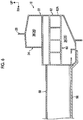
- a hydrogen tank (fuel cell) 47 may be arranged along the vehicle front-rear direction on the lower side of a tunnel portion 50 protruding along the vehicle front-rear direction in the middle portion of a floor panel 48 in the vehicle width direction in a case where, for example, the hydrogen tank 47 has a large diameter as illustrated in FIG. 5 .
- a floor cross member 52 extends between a pair of rocker panels 54 arranged at both ends of the floor panel 48 in the vehicle width direction with the tunnel portion 50 between the rocker panels 54.
- the floor cross member 52 is formed along the shape of the tunnel portion 50 herein, the present invention is not limited thereto.
- two floor cross members may also be disposed along the vehicle width direction after the floor cross member is divided by the tunnel portion although this is not illustrated.
- one end of the floor cross member in a longitudinal direction is coupled with the rocker panel and the other end of the floor cross member in the longitudinal direction is coupled with the tunnel portion.
- the rocker panel allows a reaction force from the tunnel portion to be obtained by the transmission load that is transmitted from the rocker panel to the floor cross member.
- it is desirable that the rigidity of the tunnel portion itself is increased by, for example, a reinforcing member being arranged in the tunnel portion.
- the second embodiment is also applicable with respect to gasoline cars.
- a third shock absorbing portion 60 disposed to overlap a floor cross member 58 arranged above the floor panel 56 in vehicle side view is disposed on a lower portion 62A side of a rocker panel 62.
- a configuration of a vehicle lower portion structure according to a third embodiment will be described below.
- the ladder-shaped second shock absorbing portion 38 overlapping the floor cross member 18 in vehicle side view is disposed in the upper closed sectional portion 36 of the rocker panel 14 as illustrated in FIG. 2 .
- the battery pack 20 is arranged on the lower side of the floor panel 12, and the ladder-shaped first shock absorbing portion 40 overlapping the battery pack 20 in vehicle side view is disposed in the lower closed sectional portion 34 of the rocker panel 14.
- no ladder-shaped second shock absorbing portion 38 (refer to FIG. 2 ) is disposed in the upper closed sectional portion 36 of a rocker panel 63 although the ladder-shaped first shock absorbing portion 40 is disposed in the lower closed sectional portion 34 of the rocker panel 63 as illustrated in FIG. 8 .
- a rocker panel 65 illustrated in FIG. 7 is substantially similar in configuration to the rocker panel 63, and thus description will be omitted as in the first embodiment.
- the lateral wall portion 24C connecting the upper inner wall portion 24A and the lower inner wall portion 24B constituting a part of the inner portion 24 of the rocker panel 63 and formed along the vehicle up-down direction to each other along the substantially horizontal direction connects the inner portion 24 and the outer portion 22 to each other by extending to the outer portion 22 side of the rocker panel 63.
- a partition wall 25 partitioning an upper portion 63A and a lower portion 63B of the rocker panel 63 from each other is disposed along the substantially horizontal direction.
- the partition wall 25 and the lateral wall portion 24C are integrally formed, the partition wall 25 and the lateral wall portion 24C have different names so that confusion is avoided.
- the lateral wall portion 24C is slightly inclined toward the lower side as the lateral wall portion 24C heads for the inner side in the vehicle width direction, the lateral wall portion 24C is formed along the substantially horizontal direction in a tip portion.
- three first connecting walls 40C are disposed in the first shock absorbing portion 40, the present invention is not limited thereto and the number may be four or more as well. In a case where the number of the first connecting walls 40C is increased at the same plate thickness, the rigidity of the first shock absorbing portion 40 itself can be improved and the amount of energy absorbed when the impact load is input can be increased.
- the floor cross member 18 is configured to include a front wall portion 18A disposed in a front portion in the vehicle front-rear direction, a rear wall portion 18B disposed in a rear portion in the vehicle front-rear direction, and an upper wall portion 18C connecting the upper end of the front wall portion 18A and the upper end of the rear wall portion 18B to each other in the vehicle horizontal direction.
- a plurality of the floor cross members 18 is illustrated in FIG. 7 , and a bracket 21 for a seat for an occupant to sit on is attached to the upper wall portion 18C of one of the floor cross members 18 that is in the middle portion in the vehicle front-rear direction. Accordingly, the upper wall portion 18C is lower in height-direction position than the upper wall portions 18C of the other floor cross members 18.
- a flange portion 18D extends toward the front side from the lower end of the front wall portion 18A of the floor cross member 18, and a flange portion 18E (refer to FIG. 8 ) extends toward the rear side from the lower end of the rear wall portion 18B.
- Each of the flange portions 18D, 18E is bonded to the floor panel 12.
- a closed sectional portion 19 is formed between the floor cross member 18 and the floor panel 12.
- an upper flange portion 18F extends toward the outer side in the vehicle width direction from each end of the upper wall portion 18C of the floor cross member 18 in the vehicle width direction.
- the upper flange portion 18F is bonded to the upper surface of the inclined upper wall portion 24D of the inner portion 24 constituting a part of the upper closed sectional portion 36 of the rocker panel 63.
- flange portions respectively extend toward the front side and the rear side from both ends of the front wall portion 18A (refer to FIG. 7 ) and the rear wall portion 18B of the floor cross member 18 in the vehicle width direction and each of the flange portions is bonded to the upper inner wall portion 24A of the inner portion 24.
- the battery pack (storage battery) 20 that a lithium-ion battery, nickel-hydrogen battery, or the like constitutes is provided with a battery case 64 that has the vehicle front-rear direction as the longitudinal direction of the battery case 64 and is formed in a box shape which is flat in the vehicle up-down direction and the battery modules 20A that are accommodated in the battery case 64.
- a plurality of prismatic storage batteries constitutes the battery modules 20A.
- the battery case 64 has a peripheral wall 66 constituting the outer shape of the battery case 64, a top plate 68 (not illustrated in FIG. 7 ) constituting the lid portion of the battery case 64, and a bottom plate 70 constituting the bottom portion of the battery case 64.
- the peripheral wall 66 is formed by an elongated extrusion-molded article formed by extrusion molding of a light metal such as an aluminum alloy being bent in a rectangular frame shape and both end portions of the extrusion-molded article in a longitudinal direction being bonded to each other.
- the peripheral wall 66 has a substantially rectangular frame shape in plan view.
- the top plate 68 is formed by press molding being performed on a plate material formed of a light metal such as an aluminum alloy.
- the top plate 68 is fixed to the upper surface of an upper wall portion 66C of the peripheral wall 66 via a plurality of bolts 69.
- the bottom plate 70 is formed by press molding being performed on a plate material formed of a light metal such as an aluminum alloy.
- the bottom plate 70 is fixed to the lower surface of a lower wall portion 66D of the peripheral wall 66 by means such as welding and riveting.
- the outer edge portion of the bottom plate 70 is the fixed piece 30, and the fixed piece 30 projects to the vehicle outer side in the vehicle horizontal direction beyond the peripheral wall 66 as illustrated in FIG. 7 .
- the peripheral wall 66 is configured to include a pair of right and left side wall portions 66S facing each other in the vehicle width direction, a front wall portion 66Fr connecting the front ends of the side wall portions 66S to each other, and a rear wall portion 66Rr connecting the rear ends of the side wall portions 66S to each other.
- the front wall portion 66Fr and the rear wall portion 66Rr face each other in the vehicle front-rear direction. As illustrated in FIG.
- the peripheral wall 66 is formed such that the sectional shape of the peripheral wall 66 is a substantially B-shape (substantially the shape of two squares attached to each other) when the peripheral wall 66 is seen from a circumferential direction (longitudinal direction of the extrusion-molded article).
- the peripheral wall 66 is provided with an outer peripheral wall portion 66A forming the outer peripheral surface of the peripheral wall 66, an inner peripheral wall portion 66B facing the outer peripheral wall portion 66A and forming the inner peripheral surface of the peripheral wall 66, the upper wall portion 66C connecting the upper end of the outer peripheral wall portion 66A and the upper end of the inner peripheral wall portion 66B to each other in the vehicle horizontal direction, the lower wall portion 66D connecting the lower end of the outer peripheral wall portion 66A and the lower end of the inner peripheral wall portion 66B to each other in the vehicle horizontal direction, and a partition wall portion 66E connecting the up-down direction intermediate portions of the outer peripheral wall portion 66A and the inner peripheral wall portion 66B to each other in the vehicle horizontal direction.
- the peripheral wall 66 is divided into an upper portion 72 and a lower portion 74 and is separated (partitioned) into an upper space 72A and a lower space 74A by the partition wall portion 66
- a first cross member 76 extends along the vehicle width direction above the bottom plate 70 between the side wall portions 66S of the peripheral wall 66 facing each other in the vehicle width direction.
- a plurality of (three herein) the first cross members 76 is provided such that the first cross members 76 are arranged at equal intervals along the vehicle front-rear direction between the front wall portion 66Fr and the rear wall portion 66Rr.
- the first cross member 76 is formed of an elongated extrusion-molded article that is formed by extrusion molding being performed on a light metal such as an aluminum alloy.
- the first cross member 76 is formed such that the sectional shape of the first cross member 76 is a substantially B-shape (substantially the shape of two squares attached to each other, not illustrated) when the first cross member 76 is cut along a width direction substantially orthogonal to the longitudinal direction (vehicle width direction).
- the first cross member 76 is provided with a front wall portion (not illustrated) disposed in a front portion in the vehicle front-rear direction, a rear wall portion 76A disposed in a rear portion in the vehicle front-rear direction, a second lateral wall 76B connecting the upper end of the front wall portion and the upper end of the rear wall portion 76A to each other in the vehicle horizontal direction, a lower wall portion 76C connecting the lower end of the front wall portion and the lower end of the rear wall portion 76A to each other in the vehicle horizontal direction, and a partition wall portion 76D connecting the up-down direction intermediate portions of the second lateral wall 76B and the lower wall portion 76C to each other in the vehicle horizontal direction as illustrated in FIG. 8 .
- the first cross member 76 is divided into an upper portion 78 and a lower portion 80 and is separated into an upper space 78A and a lower space 80A by the partition wall portion 76D.
- the inclined upper wall portion 22B of the outer portion 22, the inclined upper wall portion 24D of the inner portion 24, and the upper wall portion 18C of the floor cross member 18 are continuously disposed in the vehicle width direction and set in an overlapping manner in vehicle side view on the upper portion 63A side of the rocker panel 63.
- the "continuous disposition in the vehicle width direction” means that the impact load F can be transmitted along the vehicle width direction, and the members adjacent to each other in the vehicle width direction do not necessarily have to be adjacent to each other and may have a slight gap as well. At least parts of the members adjacent to each other in the vehicle width direction may also overlap each other in the vehicle up-down direction.
- the "overlapping in vehicle side view” means a state where the impact load F can be transmitted along the vehicle width direction, and the members disposed adjacent to each other in the vehicle width direction may overlap each other in vehicle side view in at least parts in the vehicle up-down direction. Still, when it comes to a member in which a plurality of members is bonded and integrated while overlapping each other in the vehicle up-down direction (integrated member), the impact load F is transmitted in the entire integrated member, and thus a part of the integrated member may overlap the members disposed adjacent to each other in the vehicle width direction in vehicle side view.
- the partition wall 25 and the lateral wall portion 24C of the rocker panel 63, the floor panel 12, the flange portion 18D (refer to FIG. 7 ) of the floor cross member 18, and the flange portion 18E are continuously disposed in the vehicle width direction and set in an overlapping manner in vehicle side view on the upper portion 63A side of the rocker panel 63.
- the floor panel 12 is bonded onto the lateral wall portion 24C of the rocker panel 63 and the flange portion 18D and the flange portion 18E of the floor cross member 18 are bonded onto the floor panel 12.
- the lateral wall portion 24C of the rocker panel 63, the floor panel 12, and the flange portion 18D and the flange portion 18E of the floor cross member 18 partially overlap each other in the vehicle up-down direction.
- the lateral wall portion 24C of the rocker panel 63, the floor panel 12, and the flange portion 18D and the flange portion 18E of the floor cross member 18 are bonded in an integrated state, and a part of the element overlaps the partition wall 25 of the rocker panel 63 in vehicle side view.
- the first lateral wall 40A of the first shock absorbing portion 40, the upper wall portion 66C of the peripheral wall 66 of the battery case 64, and the second lateral wall 76B of the first cross member 76 are continuously disposed in the vehicle width direction and set in an overlapping manner in vehicle side view.
- the first lateral wall 40B of the first shock absorbing portion 40 of the rocker panel 63, the partition wall portion 66E of the peripheral wall 66 of the battery case 64, and the partition wall portion (second lateral wall) 76D of the first cross member 76 are continuously disposed in the vehicle width direction and set in an overlapping manner in vehicle side view.
- the bottom wall portion 24E of the rocker panel 63, the lower wall portion 66D of the peripheral wall 66 of the battery case 64, and the lower wall portion 76C of the first cross member 76 are continuously disposed in the vehicle width direction and set in an overlapping manner in vehicle side view.
- the outer portion 22 positioned on the outer side in the vehicle width direction and the inner portion 24 positioned on the inner side in the vehicle width direction are formed integrally with each other and the outer portion 22 and the inner portion 24 form the closed sectional portion 26.
- the rigidity of the rocker panel 63 itself can be higher than in a case where a rocker panel 63 is formed by the two panels of the outer portion 22 and the inner portion 24 being coupled with each other.
- the first shock absorbing portion 40 extends in the vehicle width direction between the outer portion 22 and the inner portion 24 to overlap the battery pack 20 in vehicle side view.
- the battery pack 20 is provided with the battery case 64 as illustrated in FIG. 7 and the first cross members 76 extend along the vehicle width direction in the battery case 64. As a result, the rigidity of the battery case 64 itself is improved.
- the first cross member 76 is provided to overlap the lower closed sectional portion 34 of the rocker panel 63 in vehicle side view. Accordingly, once the impact load F is input to the rocker panel 63 during the side collision of the vehicle, for example, some of the impact load F is transmitted to the first cross member 76 side of the battery case 64 via the first shock absorbing portion 40 (transmission load F5).
- the transmission load F5 is transmitted to the first cross member 76 side of the battery case 64, a reaction force N5 from the first cross member 76 (strictly speaking, the rocker panel 65 (refer to FIG. 7 ) on the side opposite to the rocker panel 63 to which the impact load F is input through the first cross member 76 and the battery case 64) is obtained and the first shock absorbing portion 40 undergoes plastic deformation. Impact energy is absorbed by the plastic deformation of the first shock absorbing portion 40. As a result, the impact load F can be effectively reduced even in the event of a short stroke.
- the first shock absorbing portion 40 is disposed in the closed sectional portion 26 of the rocker panel 63 to overlap the battery pack 20 disposed on the lower side of the floor panel 12 in vehicle side view and the first cross member 76 of the battery case 64 is set to overlap the first shock absorbing portion 40 in vehicle side view.
- the first cross member 76 extending in the battery case 64, the peripheral wall 66 of the battery case 64, and the first shock absorbing portion 40 of the rocker panel 63 are continuously disposed in the vehicle width direction.
- the first cross member 76 is configured to include the second lateral wall 76B, the partition wall portion 76D, and the lower wall portion 76C respectively extending in the vehicle width direction.
- the peripheral wall 66 constituting the outer wall of the battery case 64 is configured to include the upper wall portion 66C, the partition wall portion 66E, and the lower wall portion 66D respectively extending in the vehicle width direction.
- the first shock absorbing portion 40 extending in the rocker panel 63 is configured to include the first lateral wall 40A and the third lateral wall 40B respectively extending in the vehicle width direction.
- the second lateral wall 76B of the first cross member 76 in the battery case 64 is set to overlap the upper wall portion 66C of the peripheral wall 66 of the battery case 64 and the first lateral wall 40A of the first shock absorbing portion 40 of the rocker panel 63 in vehicle side view.
- the impact load F is input to the rocker panel 63 during the side collision of the vehicle, some of the impact load F is transmitted to the upper wall portion 66C of the peripheral wall 66 of the battery case 64 and the second lateral wall 76B side of the first cross member 76 via the first lateral wall 40A of the first shock absorbing portion 40 of the rocker panel 63 (transmission load F51).
- transmission load F51 is transmitted to the second lateral wall 76B side of the first cross member 76
- the first lateral wall 40A of the first shock absorbing portion 40 of the rocker panel 63 obtains a reaction force N51 from the second lateral wall 76B of the first cross member 76.
- the partition wall portion 76D of the first cross member 76 is set to overlap the partition wall portion 66E of the peripheral wall 66 of the battery case 64 and the third lateral wall 40B of the first shock absorbing portion 40 of the rocker panel 63 in vehicle side view.
- the impact load F is input to the rocker panel 63 during the side collision of the vehicle, some of the rest of the impact load F is transmitted to the partition wall portion 66E of the peripheral wall 66 of the battery case 64 and the partition wall portion 76D side of the first cross member 76 via the third lateral wall 40B of the first shock absorbing portion 40 (transmission load F52).
- transmission load F52 is transmitted to the partition wall portion 76D side of the first cross member 76
- the third lateral wall 40B of the first shock absorbing portion 40 of the rocker panel 63 obtains a reaction force N52 from the partition wall portion 76D of the first cross member 76.
- the lower wall portion 76C of the first cross member 76 of the battery case 64 is set to overlap the lower wall portion 66D of the peripheral wall 66 of the battery case 64 and the bottom wall portion 24E of the rocker panel 63 in vehicle side view.
- the second lateral wall 76B of the first cross member 76 of the battery case 64, the upper wall portion 66C of the peripheral wall 66, and the first lateral wall 40A of the first shock absorbing portion 40 of the rocker panel 63 are continuously disposed in the vehicle width direction and set in an overlapping manner in vehicle side view.
- the partition wall portion 76D of the first cross member 76 of the battery case 64, the partition wall portion 66E of the peripheral wall 66, and the third lateral wall 40B of the first shock absorbing portion 40 of the rocker panel 63 are continuously disposed in the vehicle width direction and set in an overlapping manner in vehicle side view.
- the lower wall portion 76C of the first cross member 76 of the battery case 64, the lower wall portion 66D of the peripheral wall 66, and the bottom wall portion 24E of the rocker panel 63 are continuously disposed in the vehicle width direction and set in an overlapping manner in vehicle side view.
- the impact load F can be effectively transmitted to the battery pack 20 side (transmission load F5) and the first shock absorbing portion 40 of the rocker panel 63 can be further effectively subjected to plastic deformation by the reaction force N5 from the battery pack 20 being obtained in a reliable manner. Impact energy is absorbed by the plastic deformation of the first shock absorbing portion 40.
- the first shock absorbing portion 40 is disposed in the closed sectional portion 26 of the rocker panel 63 and the second lateral wall 76B constituting at least a part of the first cross member 76 of the battery case 64 is set to overlap the first lateral wall 40A of the first shock absorbing portion 40 constituting at least a part of the first shock absorbing portion 40 in vehicle side view. Accordingly, the reaction force N51 from the first cross member 76 can be effectively obtained on the rocker panel 63 side.
- the reaction force N52 from the first cross member 76 can be effectively obtained on the rocker panel 63 side by the partition wall portion 76D of the first cross member 76 being set to overlap the third lateral wall 40B of the first shock absorbing portion 40 in vehicle side view as is the case with the second lateral wall 76B of the first cross member 76.
- the reaction force N53 from the first cross member 76 can be effectively obtained on the rocker panel 63 side by the lower wall portion 76C of the first cross member 76 being set to overlap the bottom wall portion 24E of the rocker panel 63 in vehicle side view.
- the first cross member 76 contributes to the generation of a high load in the configuration above, and thus the impact load F can be effectively reduced even in the event of a short stroke by the amount of the impact energy absorption being increased.
- the inclined upper wall portion 22B of the outer portion 22, the inclined upper wall portion 24D of the inner portion 24 of the rocker panel 63, and the upper wall portion 18C of the floor cross member 18 are continuously disposed in the vehicle width direction and set in an overlapping manner in vehicle side view on the upper portion 63A side of the rocker panel 63.
- the partition wall 25 and the lateral wall portion 24C of the rocker panel 63, the floor panel 12, the flange portion 18D (refer to FIG. 7 ) of the floor cross member 18, and the flange portion 18E are continuously disposed in the vehicle width direction and set in an overlapping manner in vehicle side view.
- the impact load F can be effectively transmitted to the floor cross member 18 side (transmission load F6) and the rocker panel 63 undergoes plastic deformation by obtaining a reaction force N6 from the floor cross member 18 once the impact load F is input to the rocker panel 63 during the side collision of the vehicle as is the case with the lower portion 63B side of the rocker panel 63. As a result, impact energy is further absorbed.
- the inclined upper wall portion 22B of the outer portion 22, the inclined upper wall portion 24D of the inner portion 24, and the upper wall portion 18C of the floor cross member 18 are continuously disposed in the vehicle width direction and set in an overlapping manner in vehicle side view on the upper portion 63A side of the rocker panel 63.
- the inclined upper wall portion 22B of the rocker panel 63 obtains a reaction force N61 from the upper wall portion 18C of the floor cross member 18 (strictly speaking, the rocker panel 65 (refer to FIG. 7 ) positioned on the side opposite to the rocker panel 63 to which the transmission load F61 is transmitted through the floor cross member 18).
- the partition wall 25 and the lateral wall portion 24C of the rocker panel 63, the floor panel 12, the flange portion 18D (refer to FIG. 7 ) of the floor cross member 18, and the flange portion 18E are continuously disposed in the vehicle width direction and set in an overlapping manner in vehicle side view.
- the partition wall 25 of the rocker panel 63 obtains a reaction force N62 from the floor panel 12 and the flange portions 18D, 18E of the floor cross member 18 (strictly speaking, the rocker panel 65 (refer to FIG. 7 ) positioned on the side opposite to the rocker panel 63 to which the transmission load F62 is transmitted through the floor panel 12 and the flange portions 18D, 18E of the floor cross member 18).
- some of the impact load F input to the rocker panel 63 is transmitted to the floor cross member 18 side (transmission load F6) via the upper portion 63A side of the rocker panel 63 including the partition wall 25 of the rocker panel 63 during the side collision of the vehicle.
- transmission load F6 is transmitted to the floor cross member 18, the rocker panel 63 obtains the reaction force N6 from the floor cross member 18.
- the upper portion 63A side of the rocker panel 63 undergoes plastic deformation and impact energy is absorbed.
- impact energy can be further absorbed by the plastic deformation of the upper portion 63A side of the rocker panel 63 including the partition wall 25 of the rocker panel 63 and the first shock absorbing portion 40 disposed on the lower portion 63B side of the rocker panel 63.
- a load transmission path C for transmission to the battery pack 20 side via the first shock absorbing portion 40 of the rocker panel 63 and a load transmission path D for transmission to the floor cross member 18 side via the upper portion 63A side of the rocker panel 63 including the partition wall 25 of the rocker panel 63 during the side collision of the vehicle can be formed. Accordingly, load dispersion can be aimed for regarding the impact load F input to the rocker panel 63.
- inward folding of the rocker panel 63 can be suppressed by the use of the reaction force N5 from the battery pack 20 and the reaction force N6 from the floor cross member 18 by the first shock absorbing portion 40 and the partition wall 25 being disposed in the closed sectional portion 26 of the rocker panel 63 and the first shock absorbing portion 40 and the partition wall 25 being disposed to overlap the battery pack 20 and the floor cross member 18 in vehicle side view, respectively.
- the inclined upper wall portion 22B of the outer portion 22, the inclined upper wall portion 24D of the inner portion 24, and the upper wall portion 18C of the floor cross member 18 are continuously disposed in the vehicle width direction and set in an overlapping manner in vehicle side view on the upper portion 63A side of the rocker panel 63 as illustrated in FIG. 8 .
- the upper wall portion 18C of the floor cross member 18 and the inclined upper wall portion 24D of the inner portion 24 do not necessarily have to overlap each other in vehicle side view and the floor cross member 18 is optional.
- the partition wall 25 is disposed alone on the upper portion 63A side of the rocker panel 63 instead of the second shock absorbing portion 38 (refer to FIG. 2 ) in the third embodiment, it is a matter of course that the second shock absorbing portion 38 may also be disposed.
- the rate of the impact energy absorption can be adjusted on the upper portion 63A side and the lower portion 63B side of the rocker panel 63 during the side collision of the vehicle by the shape of the shock absorbing portion being changed.
- the battery pack 20 is used as the drive force supply device for supplying the electric power to the power unit as illustrated in FIG. 7 in the third embodiment
- a case where a fuel cell 82 illustrated in FIG. 9 is used as the drive force supply device will be described in a fourth embodiment. In the following description, description will be omitted with regard to substantially the same configuration as in the third embodiment.
- the fuel cell 82 is provided with a tank case 84 that has the vehicle front-rear direction as the longitudinal direction of the tank case 84 and is formed in a box shape which is flat in the vehicle up-down direction as is the case with the battery pack 20 (refer to FIG. 7 ) described in the third embodiment.
- a plurality of hydrogen tanks (fuel tanks) 86 filled with, for example, hydrogen is accommodated in the tank case 84.
- the tank case 84 has the peripheral wall 66, the top plate 68, and the bottom plate 70 as is the case with the battery case 64 (refer to FIG. 7 ).
- the member has the same configuration as the battery case 64, and thus description thereof will be omitted.
- the (13 herein) hydrogen tanks 86 accommodated in the tank case 84 are arranged along the vehicle front-rear direction and disposed along the vehicle width direction in the tank case 84. Accordingly, in the fourth embodiment, a plurality of (12 herein) second cross members 88 extends along the vehicle width direction above the bottom plate 70 between the side wall portions 66S of the peripheral wall 66 facing each other in the vehicle width direction. The rigidity of the tank case 84 itself is improved by the second cross members 88 extending along the vehicle width direction in the tank case 84 as described above.
- the hydrogen tanks 86 disposed next to each other in the vehicle front-rear direction are partitioned from each other by the second cross members 88. As illustrated in FIG. 10 , both end portions of a tank body 86A in the longitudinal direction (vehicle width direction herein) are set such that the end portions are not in direct contact with the inner peripheral wall portion 66B of the peripheral wall 66.
- the first shock absorbing portion 40 extends in the vehicle width direction between the outer portion 22 and the inner portion 24 to overlap the fuel cell 82 in vehicle side view in the closed sectional portion 26 of the rocker panel 63.
- the second cross members 88 extend along the vehicle width direction in the tank case 84 as illustrated in FIG. 9 .
- the second cross member 88 is provided to overlap the ladder-shaped shock absorbing portion (fourth shock absorbing portion) 40 disposed in the lower closed sectional portion 34 of the rocker panel 63 in vehicle side view.
- the configuration of the second cross member 88 and the relationship between the second cross member 88 and the first shock absorbing portion 40 are substantially the same as the configuration of the first cross member 76 illustrated in FIG. 8 and the relationship between the first cross member 76 illustrated in FIG. 8 and the first shock absorbing portion 40.
- rear wall portion 76A, the second lateral wall 76B, the lower wall portion 76C, and the partition wall portion 76D of the first cross member 76 respectively replaced with a rear wall portion 88A, an upper wall portion 88B, a lower wall portion 88C, and a fourth lateral wall 88D in the second cross member 88 illustrated in FIG. 10 .
- the second shock absorbing portion 38 is disposed at a position (on the upper portion 46A side of the rocker panel 46) not overlapping the hydrogen tank 44 in vehicle side view in the rocker panel 46 as illustrated in FIG. 4 and the impact load F is not input to the hydrogen tank 44 side.
- the rigidity of the tank case 84 itself is improved by the tank case 84 accommodating the hydrogen tanks 86 being disposed in the fuel cell 82 as illustrated in FIG. 9 and the second cross members 88 extending along the vehicle width direction in the peripheral wall 66 constituting the outer shape of the tank case 84.
- both end portions of the tank body 86A in the longitudinal direction are set such that the end portions are not in direct contact with the inner peripheral wall portion 66B of the peripheral wall 66.
- the rocker panel 63 obtains a reaction force N7 from the second cross member 88 (strictly speaking, the rocker panel 65 (refer to FIG. 7 ) on the side opposite to the rocker panel 63 to which the transmission load F7 is transmitted through the second cross member 88) once the transmission load F7 is transmitted to the second cross member 88 side of the tank case 84.
- the first shock absorbing portion 40 of the rocker panel 63 undergoes plastic deformation and impact energy is absorbed.
- the impact load can be effectively reduced even in the event of a short stroke, and thus some of the impact load F can be transmitted to the fuel cell 82 side.
- the first shock absorbing portion 40 is disposed in the closed sectional portion 26 of the rocker panel 63 and the position of the second cross member 88 of the tank case 84 is set to overlap the first shock absorbing portion 40 in vehicle side view. Accordingly, the reaction force N7 from the second cross member 88 can be used and inward folding of the rocker panel 63 can be suppressed.
Landscapes
- Engineering & Computer Science (AREA)
- Mechanical Engineering (AREA)
- Chemical & Material Sciences (AREA)
- Combustion & Propulsion (AREA)
- Transportation (AREA)
- Life Sciences & Earth Sciences (AREA)
- Sustainable Development (AREA)
- Sustainable Energy (AREA)
- Arrangement Or Mounting Of Propulsion Units For Vehicles (AREA)
- Body Structure For Vehicles (AREA)
Abstract
Description
- The invention relates to a vehicle lower portion structure.
- Japanese Unexamined Patent Application Publication No.
2013-133046 JP 2013-133046 A - Once an impact load is input to the rocker panel as a result of a side collision of a vehicle and the rocker panel is deformed toward the inner side in a vehicle width direction (inner side of the rocker panel), a tensile force acts on the inner side of the rocker panel in the vehicle width direction. In the related art, the battery side frame is disposed adjacent to the rocker panel as described above, and thus a compressive force acts on the rocker panel side of the battery side frame.
- In other words, in the related art, stresses acting on each other are canceled out between the tensile force and the compressive force acting at the parts of the rocker panel and the battery side frame adjacent to each other. As a result, deformation of the rocker panel and the battery side frame is suppressed and intrusion (so-called inward folding) of the rocker panel to the inner side in the vehicle width direction is suppressed.
- In general, however, the dimension of the battery unit differs from vehicle to vehicle and, in the case of the related art, the size of the battery side frame needs to be changed in accordance with the dimension of the battery unit for inward folding of the rocker panel to be suppressed. In other words, an increase in cost may occur to the same extent as the versatility of the battery side frame itself is low.
- The invention provides a vehicle lower portion structure with which inward folding of a rocker panel can be suppressed with an increase in cost suppressed.
- A first aspect of the invention relates to a vehicle lower portion structure including a pair of rocker panels, and an electric power supply device. The rocker panels extend along a vehicle front-rear direction, and are respectively arranged on both outer sides of a vehicular floor panel in a vehicle width direction. The electric power supply device is arranged below the floor panel. The rocker panel is configured to include an outer portion, an inner portion, and a first shock absorbing portion. The outer portion is positioned to define an outer wall of the rocker panel in the vehicle width direction. The inner portion is formed integrally with the outer portion, is positioned inward of the outer portion in the vehicle width direction, and forms a closed sectional portion with the outer portion. The first shock absorbing portion extends in the vehicle width direction from the outer portion to the inner portion in the closed sectional portion and is disposed to overlap the electric power supply device in vehicle side view.
- In the vehicle lower portion structure according to the first aspect of the invention, the rocker panels are respectively arranged on both outer sides of the vehicular floor panel in the vehicle width direction and each of the rocker panels extends along the vehicle front-rear direction. The electric power supply device is arranged below the floor panel.
- Examples of the electric power supply device include a storage battery and a fuel cell. Examples of the "storage battery" include a lithium-ion battery, a nickel-hydrogen battery, and a silicon battery. The "storage battery" refers to a state where, for example, a plurality of battery modules is accommodated in a case (hereinafter, also referred to as a "battery pack").
- In the rocker panel according to the first aspect of the invention, the outer portion positioned on the outer side in the vehicle width direction and the inner portion positioned on an inner side in the vehicle width direction are formed integrally with each other and the outer portion and the inner portion form the closed sectional portion. The "integral formation" means that the outer portion and the inner portion are formed integrally with each other by extrusion, drawing, or the like.
- In the invention, the outer portion and the inner portion are formed integrally with each other in the rocker panel. Accordingly, the rigidity of the rocker panel itself can be higher than in a case where, for example, a rocker panel is formed by two, outer and inner, panels being coupled with each other.
- Welding, fastening, or the like is needed when the two, outer and inner, panels are coupled with each other for the rocker panel to be formed. In the invention, however, processing such as welding and fastening is not needed since the outer portion and the inner portion are formed integrally with each other, and thus cost reduction can be achieved to that extent.
- In the closed sectional portion of the rocker panel, the first shock absorbing portion extends in the vehicle width direction from the outer portion to the inner portion. The first shock absorbing portion is disposed to overlap the electric power supply device in vehicle side view.
- In general, an electric power supply device mounted in a vehicle is set to have a high rigidity. Accordingly, in the invention, some of an impact load input to the rocker panel during a side collision of the vehicle is transmitted to the electric power supply device side via the first shock absorbing portion by the first shock absorbing portion of the rocker panel being disposed to overlap the electric power supply device in vehicle side view.
- The electric power supply device is set to have a high rigidity as described above, and thus the rocker panel obtains a reaction force from the electric power supply device once some of the impact load input to the rocker panel is transmitted to the electric power supply device. As a result, the first shock absorbing portion of the rocker panel undergoes plastic deformation and impact energy is absorbed. In other words, the impact load can be effectively reduced even in the event of a short stroke.
- As a result, intrusion (so-called inward folding) of the rocker panel to the inner side in the vehicle width direction can be suppressed. In other words, in the invention, inward folding of the rocker panel is suppressed even in a case where a large load is locally input with respect to the rocker panel as in a so-called pole side collision.
- As described above, in the invention, inward folding of the rocker panel is suppressed by the use of the reaction force from the electric power supply device by the first shock absorbing portion being disposed in the closed sectional portion of the rocker panel and the first shock absorbing portion being disposed to overlap the electric power supply device in vehicle side view. In other words, in the invention, no separate member is needed, unlike in the related art, in suppressing inward folding of the rocker panel. In the invention, the impact load can be effectively reduced even in the event of a short stroke, and thus inward folding of the rocker panel can be suppressed irrespective of the dimension of the electric power supply device.
- The vehicle lower portion structure according to the first aspect of the invention may further include a floor cross member disposed between the rocker panels above the floor panel and extending along the vehicle width direction. The rocker panel may be configured to further include a second shock absorbing portion extending in the vehicle width direction from the outer portion to the inner portion in the closed sectional portion and disposed to overlap the floor cross member in vehicle side view.
- In the vehicle lower portion structure according to the first aspect of the invention, the floor cross member extends along the vehicle width direction between the rocker panels above the floor panel. Between the outer portion and the inner portion in the closed sectional portion of the rocker panel, the second shock absorbing portion extends in the vehicle width direction to overlap the floor cross member in vehicle side view.
- Accordingly, some of the impact load input to the rocker panel is transmitted to the floor cross member side via the second shock absorbing portion during the side collision of the vehicle. Once the impact load is input to the floor cross member, the rocker panel obtains a reaction force from the floor cross member (strictly speaking, the rocker panel on the side opposite to the rocker panel to which the impact load is input through the floor cross member). As a result, the second shock absorbing portion undergoes plastic deformation and impact energy is absorbed. In other words, in the invention, impact energy can be further absorbed by the plastic deformation of the first shock absorbing portion and the second shock absorbing portion.
- Herein, a load transmission path for transmission to the electric power supply device side via the first shock absorbing portion of the rocker panel and a load transmission path for transmission to the floor cross member side via the second shock absorbing portion of the rocker panel during the side collision of the vehicle can be formed. Accordingly, load dispersion can be aimed for regarding the impact load input to the rocker panel.
- In other words, in the invention, inward folding of the rocker panel is suppressed by the use of the reaction force from the electric power supply device and the reaction force from the floor cross member by the first shock absorbing portion and the second shock absorbing portion being disposed in the closed sectional portion of the rocker panel and the first shock absorbing portion and the second shock absorbing portion being disposed to overlap the electric power supply device and the floor cross member in vehicle side view, respectively.
- In the vehicle lower portion structure according to the first aspect of the invention, the electric power supply device may be a storage battery, the storage battery may be provided with a battery case accommodating a plurality of battery modules, and a first cross member extending along the vehicle width direction may be disposed to overlap the first shock absorbing portion in vehicle side view in the battery case.
- In the vehicle lower portion structure according to the first aspect of the invention, the storage battery is provided with the battery case accommodating the battery modules and the first cross member extends along the vehicle width direction in the battery case. As a result, the rigidity of the battery case itself is improved. In the invention, the first cross member is set to be to overlap the first shock absorbing portion in vehicle side view.
- Accordingly, once the impact load is input to the rocker panel during the side collision of the vehicle, the impact load is transmitted to the first cross member side of the battery case via the first shock absorbing portion. Once the impact load is transmitted to the first cross member side of the battery case, the rocker panel obtains a reaction force from the first cross member (strictly speaking, the rocker panel on the side opposite to the rocker panel to which the impact load is input through the first cross member and the battery case) and the first shock absorbing portion undergoes plastic deformation. As a result, impact energy is absorbed and the impact load can be effectively reduced even in the event of a short stroke.
- As described above, in the invention, the first shock absorbing portion is disposed in the closed sectional portion of the rocker panel and the position of the first cross member of the battery case is set to overlap the first shock absorbing portion in vehicle side view. Accordingly, the reaction force from the first cross member can be used and inward folding of the rocker panel can be suppressed.
- In the vehicle lower portion structure according to the first aspect of the invention, the first shock absorbing portion may be configured to include a first lateral wall extending in the vehicle width direction and the first cross member may be configured to include a second lateral wall overlapping the first lateral wall extending in the vehicle width direction in vehicle side view.
- In the vehicle lower portion structure according to the first aspect of the invention, the first shock absorbing portion is configured to include the first lateral wall extending in the vehicle width direction and the first cross member is configured to include the second lateral wall extending in the vehicle width direction.
- In the invention, the second lateral wall of the first cross member is provided to overlap the first lateral wall of the first shock absorbing portion in vehicle side view. As a result, once the impact load is input to the rocker panel during the side collision of the vehicle, the impact load is transmitted to the second lateral wall side of the first cross member of the battery case via the first lateral wall of the first shock absorbing portion.
- As described above, in the invention, the second lateral wall constituting at least a part of the first cross member of the battery case is disposed to overlap the first lateral wall constituting at least a part of the first shock absorbing portion of the rocker panel in vehicle side view, and thus the reaction force from the first cross member can be effectively obtained.
- In the vehicle lower portion structure according to the first aspect of the invention, the first shock absorbing portion may include a third lateral wall extending in the vehicle width direction and disposed in parallel to the first lateral wall and a first connecting wall connecting the first lateral wall and the third lateral wall to each other between the first lateral wall and the third lateral wall.
- In the vehicle lower portion structure according to the first aspect of the invention, the electric power supply device may be a fuel cell, the fuel cell may be provided with a tank case in which fuel tanks disposed along the vehicle width direction are arranged along the vehicle front-rear direction, and a second cross member partitioning the fuel tanks disposed next to each other in the vehicle front-rear direction from each other and extending along the vehicle width direction to overlap the first shock absorbing portion in vehicle side view may be disposed in the tank case.
- In the vehicle lower portion structure according to the first aspect of the invention, the fuel cell according to the first aspect of the invention is provided with the tank case in which the fuel tanks disposed along the vehicle width direction are arranged along the vehicle front-rear direction. The second cross member extends along the vehicle width direction in the tank case, and the fuel tanks disposed next to each other in the vehicle front-rear direction are partitioned from each other by the second cross member. The rigidity of the tank case itself is improved by the second cross member being disposed in the tank case as described above.
- In the vehicle lower portion structure according to the first aspect of the invention, the first shock absorbing portion may be configured to include a fourth lateral wall extending in the vehicle width direction and the second cross member may be configured to include a fifth lateral wall overlapping the fourth lateral wall extending in the vehicle width direction in vehicle side view.
- A second aspect of the invention relates to a vehicle lower portion structure including a pair of rocker panels, and a floor cross member. The rocker panels extend along a vehicle front-rear direction, and are respectively arranged on both outer sides of a vehicular floor panel in a vehicle width direction. The floor cross member is disposed between the rocker panels above the floor panel and extends along the vehicle width direction. The rocker panel is configured to include an outer portion, an inner portion, and a third shock absorbing portion. The outer portion is positioned on an outer side in the vehicle width direction. The inner portion is formed integrally with the outer portion, is positioned inward of the outer portion in the vehicle width direction, and forms a closed sectional portion with the outer portion. The third shock absorbing portion extends in the vehicle width direction from the outer portion to the inner portion in the closed sectional portion and is disposed to overlap the floor cross member in vehicle side view.
- In the vehicle lower portion structure according to the second aspect of the invention, the rocker panels are respectively arranged on both outer sides of the vehicular floor panel in the vehicle width direction and each of the rocker panels extends along the vehicle front-rear direction. The floor cross member extends along the vehicle width direction between the rocker panels above the floor panel.
- In the rocker panel according to the second aspect of the invention, the outer portion positioned on the outer side in the vehicle width direction and the inner portion positioned on an inner side in the vehicle width direction are formed integrally with each other and the outer portion and the inner portion form the closed sectional portion. By the outer portion and the inner portion being formed integrally with each other in the rocker panel as described above, the rigidity of the rocker panel itself can be higher than in a case where, for example, a rocker panel is formed by two, outer and inner, panels being coupled with each other.
- Between the outer portion and the inner portion in the closed sectional portion of the rocker panel, the third shock absorbing portion extends in the vehicle width direction to overlap the floor cross member in vehicle side view. Accordingly, once an impact load is input to the rocker panel during a side collision of the vehicle, some of the impact load is transmitted to the floor cross member side via the third shock absorbing portion.
- Once some of the impact load is transmitted to the floor cross member side as described above, the rocker panel obtains a reaction force from the floor cross member (strictly speaking, the rocker panel on the side opposite to the rocker panel to which the impact load is input through the floor cross member) and the third shock absorbing portion undergoes plastic deformation. As a result, impact energy is absorbed. In other words, the impact load can be effectively reduced even in the event of a short stroke.
- As described above, in the invention, inward folding of the rocker panel is suppressed by the use of the reaction force from the floor cross member by the third shock absorbing portion being disposed in the closed sectional portion of the rocker panel and the third shock absorbing portion being disposed to overlap the floor cross member in vehicle side view.
- The vehicle lower portion structure according to the second aspect of the invention may include an electric power supply device arranged below the floor panel.
- As described above, in the vehicle lower portion structure according to the second aspect of the invention, the impact load input to the rocker panel is transmitted to the floor cross member side arranged above the floor panel during the side collision of the vehicle. Accordingly, in the vehicle lower portion structure according to the first aspect of the invention, the electric power supply device is arranged below the floor panel. As a result, input of the impact load to the electric power supply device arranged below the floor panel can be forestalled. Examples of the material of the "electric power supply device" include hydrogen and alcohol.
- In the vehicle lower portion structure according to the second aspect of the invention, the electric power supply device may be a storage battery.
- In the vehicle lower portion structure according to the second aspect of the invention, the electric power supply device may be a fuel cell.
- In the vehicle lower portion structure according to the second aspect of the invention, the third shock absorbing portion may be configured to include a sixth lateral wall extending in the vehicle width direction and the floor cross member may be configured to include a seventh lateral wall overlapping the sixth lateral wall extending in the vehicle width direction in vehicle side view.
- In the vehicle lower portion structure according to the second aspect of the invention, the third shock absorbing portion may include an eighth lateral wall extending in the vehicle width direction and disposed in parallel to the sixth lateral wall and a second connecting wall connecting the sixth lateral wall and the eighth lateral wall to each other between the sixth lateral wall and the eighth lateral wall.
- The vehicle lower portion structure according to the second aspect of the invention may further include a tunnel portion protruding toward an inside of a vehicle cabin and extending along the vehicle front-rear direction in a middle portion of the floor panel in the vehicle width direction. The floor cross member may extends between the rocker panels with the tunnel portion between the rocker panels.
- In the vehicle lower portion structure according to the second aspect of the invention, the tunnel portion protruding toward the inside of the vehicle cabin and extending along the vehicle front-rear direction is disposed in the middle portion of the floor panel in the vehicle width direction.
- The "floor cross member extending in the vehicle width direction between the rocker panels with the tunnel portion between the rocker panels" includes a case where the floor cross member is divided by the tunnel portion and two floor cross members are disposed along the vehicle width direction as well as a case where the floor cross member is formed along the shape of the tunnel portion and one floor cross member is disposed along the vehicle width direction.
- In the case of the former, both ends of the floor cross member in a longitudinal direction are coupled with the rocker panels on both end sides of the floor panel in the vehicle width direction. Accordingly, the rocker panel to which the impact load is input obtains a reaction force from the rocker panel on the side opposite to the rocker panel to which the impact load is input by the transmission load transmitted to the floor cross member via the rocker panel.
- In the case of the latter, one end of the floor cross member in the longitudinal direction is coupled with the rocker panel on one end side of the floor panel in the vehicle width direction and the other end of the floor cross member in the longitudinal direction is coupled with the tunnel portion. Accordingly, the rocker panel to which the impact load is input obtains a reaction force from the tunnel portion by the transmission load transmitted to the floor cross member via the rocker panel. Accordingly, in this case, it is desirable that the rigidity of the tunnel portion itself is increased by, for example, a reinforcing member being arranged in the tunnel portion.
- As described above, in the invention, the impact load can be effectively reduced even in the event of a short stroke, and thus a large-capacity fuel cell can be arranged below the tunnel portion.
- The vehicle lower portion structure according to the second aspect of the invention may further include a fourth shock absorbing portion extending in the vehicle width direction from the outer portion to the inner portion in the closed sectional portion and disposed to overlap the electric power supply device in vehicle side view.
- In the invention, the second cross member is provided to overlap the fourth shock absorbing portion in vehicle side view. Accordingly, once the impact load is input to the rocker panel during the side collision of the vehicle, the impact load is transmitted to the second cross member side of the tank case via the fourth shock absorbing portion.
- Once the impact load is transmitted to the second cross member side of the tank case, the rocker panel obtains a reaction force from the second cross member (strictly speaking, the rocker panel on the side opposite to the rocker panel to which the impact load is input through the second cross member and the tank case) and the fourth shock absorbing portion undergoes plastic deformation. As a result, impact energy is absorbed and the impact load can be effectively reduced even in the event of a short stroke.
- As described above, in the invention, the fourth shock absorbing portion is disposed in the closed sectional portion of the rocker panel and the position of the second cross member of the tank case is set to overlap the fourth shock absorbing portion in vehicle side view. Accordingly, the reaction force from the second cross member can be used and inward folding of the rocker panel can be suppressed.
- As described above, the vehicle lower portion structure according to the first aspect of the invention has an effect in that inward folding of the rocker panel can be suppressed with an increase in cost suppressed.
- In addition, the vehicle lower portion structure according to the first aspect of the invention has an effect in that the impact load can be effectively reduced even in the event of a short stroke.
- Furthermore, the vehicle lower portion structure according to the first aspect of the invention has an effect in that inward folding of the rocker panel can be suppressed by the use of the reaction force from the first cross member.
- The vehicle lower portion structure according to the second aspect of the invention has an effect in that inward folding of the rocker panel can be suppressed with an increase in cost suppressed.
- In addition, the vehicle lower portion structure according to the second aspect of the invention has an effect in that impact load transmission to the fuel cell can be forestalled.
- Furthermore, the vehicle lower portion structure according to the second aspect of the invention has an effect in that a large-capacity fuel cell can be arranged.
- Moreover, the vehicle lower portion structure according to the second aspect of the invention has an effect in that inward folding of the rocker panel can be suppressed by the use of the reaction force from the second cross member.
- Features, advantages, and technical and industrial significance of exemplary embodiments of the invention will be described below with reference to the accompanying drawings, in which like numerals denote like elements, and wherein:
-
FIG. 1 is a plan view of a vehicle lower portion to which a vehicle lower portion structure according to a first embodiment is applied; -
FIG. 2 is a cross-sectional view cut along line II-II ofFIG. 1 ; -
FIG. 3 is a sectional view corresponding toFIG. 2 and illustrating a modification example of the vehicle lower portion structure according to the first embodiment; -
FIG. 4 is a sectional view corresponding toFIG. 2 and illustrating a vehicle lower portion structure according to a second embodiment; -
FIG. 5 is a sectional view corresponding toFIG. 2 and illustrating a first modification example of the vehicle lower portion structure according to the second embodiment; -
FIG. 6 is a sectional view corresponding toFIG. 2 and illustrating a second modification example of the vehicle lower portion structure according to the second embodiment; -
FIG. 7 is an exploded perspective view illustrating a battery pack and a vehicle lower portion to which a vehicle lower portion structure according to a third embodiment is applied; -
FIG. 8 is a cross-sectional view cut along line VIII-VIII of the battery pack including the vehicle lower portion illustrated inFIG. 7 ; -
FIG. 9 is a perspective view of a fuel cell mounted in a vehicle lower portion to which a vehicle lower portion structure according to a fourth embodiment is applied; and -
FIG. 10 is a sectional view cut along line X-X ofFIG. 9 including the vehicle lower portion illustrated inFIG. 7 . - Hereinafter, a vehicle lower portion structure according to embodiments of the invention will be described with reference to accompanying drawings. The arrows FR, UP, and RH that are appropriately shown in each of the drawings represent the forward direction, the upward direction, and the rightward direction of a vehicle to which the vehicle floor portion structure according to an embodiment of the invention is applied, respectively. Unless otherwise noted, the front-rear, up-down, and right-left directions in the following description refer to the front and rear in the vehicle front-rear direction, the top and bottom in the vehicle up-down direction, and the right and left in a case where the vehicle is in the forward direction, respectively.
- A configuration of the vehicle lower portion structure according to a first embodiment will be described below.
FIG. 1 is a plan view of a vehiclelower portion 10 to which the vehicle lower portion structure according to the first embodiment is applied, andFIG. 2 is a cross-sectional view cut along line II-II ofFIG. 1 . - As illustrated in
FIG. 1 , afloor panel 12 extends along a vehicle width direction and the vehicle front-rear direction in the vehiclelower portion 10. Abead portion 12A intermittently protrudes along the vehicle front-rear direction in thefloor panel 12, and a plurality of thebead portions 12A is arranged along the vehicle width direction. The rigidity of thefloor panel 12 itself is improved by thebead portion 12A being formed. -
Rocker panels floor panel 12 in the vehicle width direction, and afloor cross member 18 extends along the vehicle width direction between therocker panel 14 and therocker panel 16 above thefloor panel 12. Thefloor cross member 18 is disposed between thebead portion 12A and thebead portion 12A disposed along the vehicle front-rear direction. - As illustrated in
FIG. 2 , a battery pack (storage battery) 20 is arranged on the lower side of thefloor panel 12 as a drive force supply device for supplying electric power to a power unit such as a motor. A lithium-ion battery, a nickel-hydrogen battery, or the like constitutes thebattery pack 20. - As described above, the
rocker panels floor panel 12 in the vehicle width direction. Therocker panels rocker panel 16 has substantially the same configuration as therocker panel 14, and thus description of therocker panel 16 will be omitted. - In the first embodiment, the
rocker panel 14 is configured to include anouter portion 22 positioned on the outer side in the vehicle width direction and aninner portion 24 positioned on the inner side in the vehicle width direction as illustrated inFIG. 2 . Therocker panel 14 is formed of a metal such as an aluminum alloy. Theouter portion 22 and theinner portion 24 are formed integrally with each other by extrusion, drawing, or the like, and theouter portion 22 and theinner portion 24 form a closedsectional portion 26. - The
outer portion 22 is configured to include anouter wall portion 22A, an inclinedupper wall portion 22B, and an inclinedlower wall portion 22C. In a sectional shape cut along the vehicle width direction, theouter wall portion 22A is formed along the vehicle up-down direction, the inclinedupper wall portion 22B is disposed on the upper side of theouter wall portion 22A and is inclined toward the upper side as the inclinedupper wall portion 22B heads for the inner side in the vehicle width direction, and the inclinedlower wall portion 22C is disposed on the lower side of theouter wall portion 22A and is inclined toward the lower side as the inclinedlower wall portion 22C heads for the inner side in the vehicle width direction. - The
inner portion 24 is configured to include an upperinner wall portion 24A and a lowerinner wall portion 24B. In the sectional shape cut along the vehicle width direction, the upperinner wall portion 24A is formed along the vehicle up-down direction on the upper portion side of theinner portion 24 and the lowerinner wall portion 24B is formed along the vehicle up-down direction on the lower portion side of theinner portion 24. The lowerinner wall portion 24B is positioned closer to the inner side in the vehicle width direction than the upperinner wall portion 24A, and alateral wall portion 24C formed along a substantially horizontal direction is disposed between the lowerinner wall portion 24B and the upperinner wall portion 24A. Accordingly, thelateral wall portion 24C is formed to be connected to the upperinner wall portion 24A and the lowerinner wall portion 24B. - An inclined
upper wall portion 24D is disposed on the upper side of the upperinner wall portion 24A. The inclinedupper wall portion 24D is inclined toward the upper side as the inclinedupper wall portion 24D heads for the outer side in the vehicle width direction. The inclinedupper wall portion 24D is formed to be connected to the inclinedupper wall portion 22B of theouter portion 22. Aflange portion 28 extends toward the upper side from atop portion 27 in which the inclinedupper wall portion 24D of theinner portion 24 and the inclinedupper wall portion 22B of theouter portion 22 are connected to each other. A lower end portion of a pillar (not illustrated) is coupled with theflange portion 28. - A
bottom wall portion 24E formed along the substantially horizontal direction toward the outer side in the vehicle width direction is disposed on the lower side of the lowerinner wall portion 24B, and thebottom wall portion 24E is formed to be connected to the inclinedlower wall portion 22C of theouter portion 22. Afastener 32 can be inserted into thebottom wall portion 24E. A fixedpiece 30 disposed in thebattery pack 20 can be fastened and fixed to therocker panel 14 via thefastener 32. - As described above, the upper
inner wall portion 24A of theinner portion 24 is positioned closer to the outer side in the vehicle width direction than the lowerinner wall portion 24B. As a result, anupper portion 14A and alower portion 14B of therocker panel 14 have different closed sectional portion areas. In other words, the area of a lower closedsectional portion 34 disposed on thelower portion 14B side of therocker panel 14 exceeds the area of an upper closedsectional portion 36 disposed on theupper portion 14A side of therocker panel 14 and the rigidity of thelower portion 14B side of therocker panel 14 is set to exceed the rigidity of theupper portion 14A side of therocker panel 14. - A ladder-shaped second
shock absorbing portion 38 is disposed in the upper closedsectional portion 36 of therocker panel 14, and the secondshock absorbing portion 38 is disposed to overlap thefloor cross member 18 in vehicle side view. A ladder-shaped firstshock absorbing portion 40 is formed in the lower closedsectional portion 34 of therocker panel 14, and the firstshock absorbing portion 40 is disposed to overlap thebattery pack 20 in vehicle side view. - Each of the second
shock absorbing portion 38 and the firstshock absorbing portion 40 will be described below. The secondshock absorbing portion 38 is provided with anupper wall 38A extending along the substantially horizontal direction (vehicle width direction) between the upperinner wall portion 24A of theinner portion 24 and theouter wall portion 22A of theouter portion 22. Alower wall 38B facing theupper wall 38A is formed on the lower side of theupper wall 38A, thelower wall 38B is connected to thelateral wall portion 24C, and thelower wall 38B partitions theupper portion 14A and thelower portion 14B of therocker panel 14 from each other. Accordingly, thelower wall 38B is also referred to as a "partition wall". A plurality of (two herein) connectingwalls 38C extends in the up-down direction between theupper wall 38A and thelower wall 38B. - The first
shock absorbing portion 40 is provided with a firstlateral wall 40A extending along the substantially horizontal direction (vehicle width direction) between the lowerinner wall portion 24B of theinner portion 24 and theouter wall portion 22A of theouter portion 22. A thirdlateral wall 40B facing the firstlateral wall 40A is formed on the lower side of the firstlateral wall 40A, and a plurality of (three herein) first connectingwalls 40C extends in the up-down direction between the firstlateral wall 40A and the thirdlateral wall 40B. - The action and effect of the vehicle lower portion structure according to the first embodiment will be described below.
- As illustrated in
FIG. 2 , in the first embodiment, theouter portion 22 and theinner portion 24 are formed integrally with each other in therocker panel 14 and theouter portion 22 and theinner portion 24 form the closedsectional portion 26. - As a result, the rigidity of the
rocker panel 14 itself can be higher than in a case (not illustrated) where, for example, a rocker panel is formed by two, outer and inner, panels being coupled with each other. Welding, fastening, or the like is needed when the two, outer and inner, panels are coupled with each other for the rocker panel to be formed. In the first embodiment, however, processing such as welding and fastening is not needed since theouter portion 22 and theinner portion 24 are formed integrally with each other, and thus cost reduction can be achieved to that extent. - In the first embodiment, the second
shock absorbing portion 38 extends in the vehicle width direction to overlap thefloor cross member 18 in vehicle side view between theouter portion 22 and theinner portion 24 in theupper portion 14A of the rocker panel 14 (in the upper closed sectional portion 36). In thelower portion 14B of the rocker panel 14 (in the lower closed sectional portion 34), the firstshock absorbing portion 40 extends in the vehicle width direction to overlap thebattery pack 20 in vehicle side view between theouter portion 22 and theinner portion 24. - Accordingly, once an impact load F is input to the
rocker panel 14 during a side collision of the vehicle, some of the impact load F input to therocker panel 14 is transmitted to thefloor cross member 18 side via the secondshock absorbing portion 38 disposed on theupper portion 14A side of the rocker panel 14 (transmission load F1) and transmitted to thebattery pack 20 side via the firstshock absorbing portion 40 disposed on thelower portion 14B side of the rocker panel 14 (transmission load F2). - Once the transmission load F1 is transmitted to the
floor cross member 18 via the secondshock absorbing portion 38, a reaction force N1 is obtained from the floor cross member 18 (strictly speaking, the rocker panel 16 (refer toFIG. 1 ) on the side opposite to therocker panel 14 to which the impact load F is input through the floor cross member 18) in therocker panel 14. Once the transmission load F2 is transmitted to thebattery pack 20 via the firstshock absorbing portion 40, a reaction force N2 is obtained from the battery pack 20 (strictly speaking, the rocker panel 16 (refer toFIG. 1 ) on the side opposite to therocker panel 14 to which the impact load F is input through the battery pack 20) in therocker panel 14. As a result, each of the secondshock absorbing portion 38 and the firstshock absorbing portion 40 undergoes plastic deformation and impact energy is absorbed. - Accordingly, in the first embodiment, the impact load F can be effectively reduced even in the event of a short stroke. Therefore, inward folding of the
rocker panel 14 can be suppressed even in a case (not illustrated) where, for example, a large load is locally input with respect to therocker panel 14 as in a pole side collision. In other words, according to the first embodiment, inward folding of therocker panel 14 can be suppressed with an increase in cost suppressed. - In the first embodiment, some of the impact load F is transmitted to the
floor cross member 18 side via the secondshock absorbing portion 38 disposed on theupper portion 14A side of the rocker panel 14 (transmission load F1) and transmitted to thebattery pack 20 side via the firstshock absorbing portion 40 disposed on thelower portion 14B side of the rocker panel 14 (transmission load F2) as described above once the impact load F is input to therocker panel 14 during the side collision of the vehicle. - In other words, a load transmission path A for transmission to the
floor cross member 18 side via the secondshock absorbing portion 38 of therocker panel 14 and a load transmission path B for transmission to thebattery pack 20 side via the firstshock absorbing portion 40 of therocker panel 14 are formed. As a result, load dispersion can be aimed for regarding the impact load F input to therocker panel 14, and load burden ratios can also be changed in theupper portion 14A of therocker panel 14 and thelower portion 14B of therocker panel 14. - Accordingly, the transmission load F2 transmitted to the
battery pack 20 side arranged on the lower side of thefloor panel 12 can be reduced. According to the above, the rigidity of thebattery pack 20 itself can be reduced to the same extent as, for example, the transmission load F2 transmitted to thebattery pack 20 side is reduced. In this case, a reduction in the weight of thebattery pack 20 can be aimed for by the plate thickness of thebattery pack 20 being reduced. The amount by whichbattery modules 20A accommodated in thebattery pack 20 are mounted can be increased to the same extent as the plate thickness of thebattery pack 20 is reduced. - In the first embodiment, the second
shock absorbing portion 38 and the firstshock absorbing portion 40 may be formed integrally with therocker panel 14 or may be formed separately from therocker panel 14. In a case where the secondshock absorbing portion 38 and the firstshock absorbing portion 40 are formed separately from therocker panel 14, the secondshock absorbing portion 38 and the firstshock absorbing portion 40 can be formed of a material that differs from the material of therocker panel 14, and thus the degree of freedom in mechanical strength design for therocker panel 14 is improved. - Although each of the second
shock absorbing portion 38 and the firstshock absorbing portion 40 is formed in a ladder shape in the first embodiment, the shapes of the secondshock absorbing portion 38 and the firstshock absorbing portion 40 are not limited thereto. The shapes can be appropriately changed in relation to the plate thicknesses of the secondshock absorbing portion 38 and the firstshock absorbing portion 40. For example, the secondshock absorbing portion 38 and the firstshock absorbing portion 40 can be formed in a honeycomb shape by the plate thicknesses being reduced. The secondshock absorbing portion 38 and the firstshock absorbing portion 40 may have different plate thicknesses as well, and the secondshock absorbing portion 38 and the firstshock absorbing portion 40 do not necessarily have to have the same shape. - Although the second
shock absorbing portion 38 is disposed to overlap thefloor cross member 18 in vehicle side view and the firstshock absorbing portion 40 is disposed to overlap thebattery pack 20 in vehicle side view in therocker panel 14 as described above in the first embodiment, embodiments applied in the invention are not limited thereto. - In some types of vehicles and depending on vehicles, for example, no floor cross member 18 (refer to
FIG. 2 ) is disposed above thefloor panel 12 as illustrated inFIG. 3 . In this case, the firstshock absorbing portion 40 is disposed on alower portion 42B side of arocker panel 42 although the second shock absorbing portion 38 (refer toFIG. 2 ) is not disposed on anupper portion 42A side of therocker panel 42 overlapping the floor cross member 18 (refer toFIG. 2 ) in vehicle side view. Accordingly, once the impact load F is input to therocker panel 14 during the side collision of the vehicle, some of the impact load F is transmitted to thebattery pack 20 side via the first shock absorbing portion 40 (transmission load F3). - Once the impact load (transmission load F3) is transmitted to the
battery pack 20 via the firstshock absorbing portion 40, a reaction force N3 is obtained from thebattery pack 20 in therocker panel 14. As a result, the firstshock absorbing portion 40 undergoes plastic deformation, and thus impact energy is absorbed in this case as well. - Although a case where the battery pack 20 (refer to
FIG. 2 ) is used as the drive force supply device for supplying the electric power to the power unit has been described in the first embodiment, a case where a hydrogen tank (fuel cell) 44 is used as the drive force supply device as illustrated inFIG. 4 will be described in a second embodiment. Description will be omitted with regard to substantially the same configuration as in the first embodiment. - In the second embodiment, the second
shock absorbing portion 38 is disposed at a position (on anupper portion 46A side of a rocker panel 46) not overlapping thehydrogen tank 44 in vehicle side view in the rocker panel 46 as illustrated inFIG. 4 . - In this case, some of the impact load F is transmitted to the
floor cross member 18 side via the secondshock absorbing portion 38 disposed on theupper portion 46A side of the rocker panel 46 (transmission load F4) once the impact load F is input to the rocker panel 46 during the side collision of the vehicle. Once the transmission load F4 is transmitted to thefloor cross member 18 via the secondshock absorbing portion 38, a reaction force N4 is obtained from thefloor cross member 18 in the rocker panel 46. As a result, the secondshock absorbing portion 38 undergoes plastic deformation and impact energy is absorbed. - Therefore, according to the second embodiment, the impact load F can be effectively reduced even in the event of a short stroke and intrusion of the rocker panel 46 to the inner side in the vehicle width direction can be suppressed. In the second embodiment, input of the impact load F to the
hydrogen tank 44 side arranged on the lower side of thefloor panel 12 can be forestalled. - Although the
floor cross member 18 extends between therocker panels FIG. 1 in the embodiment above, a hydrogen tank (fuel cell) 47 may be arranged along the vehicle front-rear direction on the lower side of atunnel portion 50 protruding along the vehicle front-rear direction in the middle portion of afloor panel 48 in the vehicle width direction in a case where, for example, thehydrogen tank 47 has a large diameter as illustrated inFIG. 5 . - In this case, a
floor cross member 52 extends between a pair ofrocker panels 54 arranged at both ends of thefloor panel 48 in the vehicle width direction with thetunnel portion 50 between therocker panels 54. Although thefloor cross member 52 is formed along the shape of thetunnel portion 50 herein, the present invention is not limited thereto. - For example, two floor cross members may also be disposed along the vehicle width direction after the floor cross member is divided by the tunnel portion although this is not illustrated. In this case, one end of the floor cross member in a longitudinal direction is coupled with the rocker panel and the other end of the floor cross member in the longitudinal direction is coupled with the tunnel portion. Accordingly, the rocker panel allows a reaction force from the tunnel portion to be obtained by the transmission load that is transmitted from the rocker panel to the floor cross member. Accordingly, in this case, it is desirable that the rigidity of the tunnel portion itself is increased by, for example, a reinforcing member being arranged in the tunnel portion.
- Although vehicles in which the battery pack 20 (refer to
FIG. 2 ) and the hydrogen tank 44 (refer toFIG. 4 ) are used as the drive force supply device have been described in the embodiments above, the second embodiment is also applicable with respect to gasoline cars. - In the case of gasoline cars, no drive force supply device needs to be arranged on the lower side of a
floor panel 56 as illustrated in, for example,FIG. 6 . Accordingly, the position of thefloor panel 56 in the up-down direction can be set low. Therefore, a thirdshock absorbing portion 60 disposed to overlap afloor cross member 58 arranged above thefloor panel 56 in vehicle side view is disposed on alower portion 62A side of arocker panel 62. - A configuration of a vehicle lower portion structure according to a third embodiment will be described below. In the first embodiment, the ladder-shaped second
shock absorbing portion 38 overlapping thefloor cross member 18 in vehicle side view is disposed in the upper closedsectional portion 36 of therocker panel 14 as illustrated inFIG. 2 . Thebattery pack 20 is arranged on the lower side of thefloor panel 12, and the ladder-shaped firstshock absorbing portion 40 overlapping thebattery pack 20 in vehicle side view is disposed in the lower closedsectional portion 34 of therocker panel 14. - In the third embodiment, in contrast, no ladder-shaped second shock absorbing portion 38 (refer to
FIG. 2 ) is disposed in the upper closedsectional portion 36 of arocker panel 63 although the ladder-shaped firstshock absorbing portion 40 is disposed in the lower closedsectional portion 34 of therocker panel 63 as illustrated inFIG. 8 . In the following description, description will be omitted with regard to substantially the same configuration as in the first embodiment. Arocker panel 65 illustrated inFIG. 7 is substantially similar in configuration to therocker panel 63, and thus description will be omitted as in the first embodiment. - To be more specific with regard to the third embodiment, the
lateral wall portion 24C connecting the upperinner wall portion 24A and the lowerinner wall portion 24B constituting a part of theinner portion 24 of therocker panel 63 and formed along the vehicle up-down direction to each other along the substantially horizontal direction connects theinner portion 24 and theouter portion 22 to each other by extending to theouter portion 22 side of therocker panel 63. In other words, apartition wall 25 partitioning anupper portion 63A and alower portion 63B of therocker panel 63 from each other is disposed along the substantially horizontal direction. Although thepartition wall 25 and thelateral wall portion 24C are integrally formed, thepartition wall 25 and thelateral wall portion 24C have different names so that confusion is avoided. - Although the
lateral wall portion 24C is slightly inclined toward the lower side as thelateral wall portion 24C heads for the inner side in the vehicle width direction, thelateral wall portion 24C is formed along the substantially horizontal direction in a tip portion. Although three first connectingwalls 40C are disposed in the firstshock absorbing portion 40, the present invention is not limited thereto and the number may be four or more as well. In a case where the number of the first connectingwalls 40C is increased at the same plate thickness, the rigidity of the firstshock absorbing portion 40 itself can be improved and the amount of energy absorbed when the impact load is input can be increased. - As illustrated in
FIG. 7 , thefloor cross member 18 is configured to include afront wall portion 18A disposed in a front portion in the vehicle front-rear direction, arear wall portion 18B disposed in a rear portion in the vehicle front-rear direction, and anupper wall portion 18C connecting the upper end of thefront wall portion 18A and the upper end of therear wall portion 18B to each other in the vehicle horizontal direction. A plurality of thefloor cross members 18 is illustrated inFIG. 7 , and abracket 21 for a seat for an occupant to sit on is attached to theupper wall portion 18C of one of thefloor cross members 18 that is in the middle portion in the vehicle front-rear direction. Accordingly, theupper wall portion 18C is lower in height-direction position than theupper wall portions 18C of the otherfloor cross members 18. - A
flange portion 18D extends toward the front side from the lower end of thefront wall portion 18A of thefloor cross member 18, and aflange portion 18E (refer toFIG. 8 ) extends toward the rear side from the lower end of therear wall portion 18B. Each of theflange portions floor panel 12. As a result, a closed sectional portion 19 (refer toFIG. 8 ) is formed between thefloor cross member 18 and thefloor panel 12. - As illustrated in
FIG. 8 , anupper flange portion 18F extends toward the outer side in the vehicle width direction from each end of theupper wall portion 18C of thefloor cross member 18 in the vehicle width direction. Theupper flange portion 18F is bonded to the upper surface of the inclinedupper wall portion 24D of theinner portion 24 constituting a part of the upper closedsectional portion 36 of therocker panel 63. Although not illustrated, flange portions respectively extend toward the front side and the rear side from both ends of thefront wall portion 18A (refer toFIG. 7 ) and therear wall portion 18B of thefloor cross member 18 in the vehicle width direction and each of the flange portions is bonded to the upperinner wall portion 24A of theinner portion 24. - As illustrated in
FIG. 7 , in the third embodiment, the battery pack (storage battery) 20 that a lithium-ion battery, nickel-hydrogen battery, or the like constitutes is provided with abattery case 64 that has the vehicle front-rear direction as the longitudinal direction of thebattery case 64 and is formed in a box shape which is flat in the vehicle up-down direction and thebattery modules 20A that are accommodated in thebattery case 64. A plurality of prismatic storage batteries constitutes thebattery modules 20A. - As illustrated in
FIGS. 7 and8 , thebattery case 64 has aperipheral wall 66 constituting the outer shape of thebattery case 64, a top plate 68 (not illustrated inFIG. 7 ) constituting the lid portion of thebattery case 64, and abottom plate 70 constituting the bottom portion of thebattery case 64. - The
peripheral wall 66 is formed by an elongated extrusion-molded article formed by extrusion molding of a light metal such as an aluminum alloy being bent in a rectangular frame shape and both end portions of the extrusion-molded article in a longitudinal direction being bonded to each other. Theperipheral wall 66 has a substantially rectangular frame shape in plan view. Thetop plate 68 is formed by press molding being performed on a plate material formed of a light metal such as an aluminum alloy. Thetop plate 68 is fixed to the upper surface of anupper wall portion 66C of theperipheral wall 66 via a plurality ofbolts 69. - The
bottom plate 70 is formed by press molding being performed on a plate material formed of a light metal such as an aluminum alloy. Thebottom plate 70 is fixed to the lower surface of alower wall portion 66D of theperipheral wall 66 by means such as welding and riveting. The outer edge portion of thebottom plate 70 is the fixedpiece 30, and the fixedpiece 30 projects to the vehicle outer side in the vehicle horizontal direction beyond theperipheral wall 66 as illustrated inFIG. 7 . By the fixedpiece 30 being fastened (coupled) with the right and leftrocker panels 63, thebattery case 64, that is, thebattery pack 20 is fixed to therocker panels 63 while being supported from the lower side by thebottom plate 70. - A configuration of the
peripheral wall 66 will be described below. As illustrated inFIGS. 7 and8 , theperipheral wall 66 is configured to include a pair of right and leftside wall portions 66S facing each other in the vehicle width direction, a front wall portion 66Fr connecting the front ends of theside wall portions 66S to each other, and a rear wall portion 66Rr connecting the rear ends of theside wall portions 66S to each other. The front wall portion 66Fr and the rear wall portion 66Rr face each other in the vehicle front-rear direction. As illustrated inFIG. 8 , theperipheral wall 66 is formed such that the sectional shape of theperipheral wall 66 is a substantially B-shape (substantially the shape of two squares attached to each other) when theperipheral wall 66 is seen from a circumferential direction (longitudinal direction of the extrusion-molded article). - To be more specific with regard to the sectional shape of the
peripheral wall 66, theperipheral wall 66 is provided with an outerperipheral wall portion 66A forming the outer peripheral surface of theperipheral wall 66, an innerperipheral wall portion 66B facing the outerperipheral wall portion 66A and forming the inner peripheral surface of theperipheral wall 66, theupper wall portion 66C connecting the upper end of the outerperipheral wall portion 66A and the upper end of the innerperipheral wall portion 66B to each other in the vehicle horizontal direction, thelower wall portion 66D connecting the lower end of the outerperipheral wall portion 66A and the lower end of the innerperipheral wall portion 66B to each other in the vehicle horizontal direction, and apartition wall portion 66E connecting the up-down direction intermediate portions of the outerperipheral wall portion 66A and the innerperipheral wall portion 66B to each other in the vehicle horizontal direction. Theperipheral wall 66 is divided into anupper portion 72 and alower portion 74 and is separated (partitioned) into anupper space 72A and alower space 74A by thepartition wall portion 66E. - A
first cross member 76 extends along the vehicle width direction above thebottom plate 70 between theside wall portions 66S of theperipheral wall 66 facing each other in the vehicle width direction. A plurality of (three herein) thefirst cross members 76 is provided such that thefirst cross members 76 are arranged at equal intervals along the vehicle front-rear direction between the front wall portion 66Fr and the rear wall portion 66Rr. - The
first cross member 76 is formed of an elongated extrusion-molded article that is formed by extrusion molding being performed on a light metal such as an aluminum alloy. Thefirst cross member 76 is formed such that the sectional shape of thefirst cross member 76 is a substantially B-shape (substantially the shape of two squares attached to each other, not illustrated) when thefirst cross member 76 is cut along a width direction substantially orthogonal to the longitudinal direction (vehicle width direction). - To be more specific with regard to the sectional shape of the
first cross member 76, thefirst cross member 76 is provided with a front wall portion (not illustrated) disposed in a front portion in the vehicle front-rear direction, arear wall portion 76A disposed in a rear portion in the vehicle front-rear direction, a secondlateral wall 76B connecting the upper end of the front wall portion and the upper end of therear wall portion 76A to each other in the vehicle horizontal direction, alower wall portion 76C connecting the lower end of the front wall portion and the lower end of therear wall portion 76A to each other in the vehicle horizontal direction, and apartition wall portion 76D connecting the up-down direction intermediate portions of the secondlateral wall 76B and thelower wall portion 76C to each other in the vehicle horizontal direction as illustrated inFIG. 8 . Thefirst cross member 76 is divided into anupper portion 78 and alower portion 80 and is separated into anupper space 78A and alower space 80A by thepartition wall portion 76D. - In the third embodiment, the inclined
upper wall portion 22B of theouter portion 22, the inclinedupper wall portion 24D of theinner portion 24, and theupper wall portion 18C of thefloor cross member 18 are continuously disposed in the vehicle width direction and set in an overlapping manner in vehicle side view on theupper portion 63A side of therocker panel 63. - The "continuous disposition in the vehicle width direction" means that the impact load F can be transmitted along the vehicle width direction, and the members adjacent to each other in the vehicle width direction do not necessarily have to be adjacent to each other and may have a slight gap as well. At least parts of the members adjacent to each other in the vehicle width direction may also overlap each other in the vehicle up-down direction.
- The "overlapping in vehicle side view" means a state where the impact load F can be transmitted along the vehicle width direction, and the members disposed adjacent to each other in the vehicle width direction may overlap each other in vehicle side view in at least parts in the vehicle up-down direction. Still, when it comes to a member in which a plurality of members is bonded and integrated while overlapping each other in the vehicle up-down direction (integrated member), the impact load F is transmitted in the entire integrated member, and thus a part of the integrated member may overlap the members disposed adjacent to each other in the vehicle width direction in vehicle side view.
- As a specific example, the
partition wall 25 and thelateral wall portion 24C of therocker panel 63, thefloor panel 12, theflange portion 18D (refer toFIG. 7 ) of thefloor cross member 18, and theflange portion 18E are continuously disposed in the vehicle width direction and set in an overlapping manner in vehicle side view on theupper portion 63A side of therocker panel 63. - The
floor panel 12 is bonded onto thelateral wall portion 24C of therocker panel 63 and theflange portion 18D and theflange portion 18E of thefloor cross member 18 are bonded onto thefloor panel 12. In other words, thelateral wall portion 24C of therocker panel 63, thefloor panel 12, and theflange portion 18D and theflange portion 18E of thefloor cross member 18 partially overlap each other in the vehicle up-down direction. - The
lateral wall portion 24C of therocker panel 63, thefloor panel 12, and theflange portion 18D and theflange portion 18E of thefloor cross member 18 are bonded in an integrated state, and a part of the element overlaps thepartition wall 25 of therocker panel 63 in vehicle side view. - On the
lower portion 63B side of therocker panel 63 with respect to theupper portion 63A side of therocker panel 63, the firstlateral wall 40A of the firstshock absorbing portion 40, theupper wall portion 66C of theperipheral wall 66 of thebattery case 64, and the secondlateral wall 76B of thefirst cross member 76 are continuously disposed in the vehicle width direction and set in an overlapping manner in vehicle side view. - The first
lateral wall 40B of the firstshock absorbing portion 40 of therocker panel 63, thepartition wall portion 66E of theperipheral wall 66 of thebattery case 64, and the partition wall portion (second lateral wall) 76D of thefirst cross member 76 are continuously disposed in the vehicle width direction and set in an overlapping manner in vehicle side view. - The
bottom wall portion 24E of therocker panel 63, thelower wall portion 66D of theperipheral wall 66 of thebattery case 64, and thelower wall portion 76C of thefirst cross member 76 are continuously disposed in the vehicle width direction and set in an overlapping manner in vehicle side view. - The action and effect of the vehicle lower portion structure according to the third embodiment will be described below.
- As illustrated in
FIG. 8 , in therocker panel 63 according to the third embodiment, theouter portion 22 positioned on the outer side in the vehicle width direction and theinner portion 24 positioned on the inner side in the vehicle width direction are formed integrally with each other and theouter portion 22 and theinner portion 24 form the closedsectional portion 26. As a result, the rigidity of therocker panel 63 itself can be higher than in a case where arocker panel 63 is formed by the two panels of theouter portion 22 and theinner portion 24 being coupled with each other. - In the closed
sectional portion 26 of therocker panel 63, the firstshock absorbing portion 40 extends in the vehicle width direction between theouter portion 22 and theinner portion 24 to overlap thebattery pack 20 in vehicle side view. In the third embodiment, thebattery pack 20 is provided with thebattery case 64 as illustrated inFIG. 7 and thefirst cross members 76 extend along the vehicle width direction in thebattery case 64. As a result, the rigidity of thebattery case 64 itself is improved. - In the third embodiment, the
first cross member 76 is provided to overlap the lower closedsectional portion 34 of therocker panel 63 in vehicle side view. Accordingly, once the impact load F is input to therocker panel 63 during the side collision of the vehicle, for example, some of the impact load F is transmitted to thefirst cross member 76 side of thebattery case 64 via the first shock absorbing portion 40 (transmission load F5). - Once the transmission load F5 is transmitted to the
first cross member 76 side of thebattery case 64, a reaction force N5 from the first cross member 76 (strictly speaking, the rocker panel 65 (refer toFIG. 7 ) on the side opposite to therocker panel 63 to which the impact load F is input through thefirst cross member 76 and the battery case 64) is obtained and the firstshock absorbing portion 40 undergoes plastic deformation. Impact energy is absorbed by the plastic deformation of the firstshock absorbing portion 40. As a result, the impact load F can be effectively reduced even in the event of a short stroke. - As described above, in the third embodiment, the first
shock absorbing portion 40 is disposed in the closedsectional portion 26 of therocker panel 63 to overlap thebattery pack 20 disposed on the lower side of thefloor panel 12 in vehicle side view and thefirst cross member 76 of thebattery case 64 is set to overlap the firstshock absorbing portion 40 in vehicle side view. - As a result, during the side collision of the vehicle, the plastic deformation of the first
shock absorbing portion 40 is allowed to occur by the reaction force N5 from thefirst cross member 76 being used and the impact load F can be effectively reduced even in the event of a short stroke. As a result, inward folding of therocker panel 63 can be suppressed. - To be even more specific with regard to the above, in the third embodiment, the
first cross member 76 extending in thebattery case 64, theperipheral wall 66 of thebattery case 64, and the firstshock absorbing portion 40 of therocker panel 63 are continuously disposed in the vehicle width direction. - The
first cross member 76 is configured to include the secondlateral wall 76B, thepartition wall portion 76D, and thelower wall portion 76C respectively extending in the vehicle width direction. Theperipheral wall 66 constituting the outer wall of thebattery case 64 is configured to include theupper wall portion 66C, thepartition wall portion 66E, and thelower wall portion 66D respectively extending in the vehicle width direction. The firstshock absorbing portion 40 extending in therocker panel 63 is configured to include the firstlateral wall 40A and the thirdlateral wall 40B respectively extending in the vehicle width direction. - In the third embodiment, the second
lateral wall 76B of thefirst cross member 76 in thebattery case 64 is set to overlap theupper wall portion 66C of theperipheral wall 66 of thebattery case 64 and the firstlateral wall 40A of the firstshock absorbing portion 40 of therocker panel 63 in vehicle side view. - Accordingly, once the impact load F is input to the
rocker panel 63 during the side collision of the vehicle, some of the impact load F is transmitted to theupper wall portion 66C of theperipheral wall 66 of thebattery case 64 and the secondlateral wall 76B side of thefirst cross member 76 via the firstlateral wall 40A of the firstshock absorbing portion 40 of the rocker panel 63 (transmission load F51). Once the transmission load F51 is transmitted to the secondlateral wall 76B side of thefirst cross member 76, the firstlateral wall 40A of the firstshock absorbing portion 40 of therocker panel 63 obtains a reaction force N51 from the secondlateral wall 76B of thefirst cross member 76. - The
partition wall portion 76D of thefirst cross member 76 is set to overlap thepartition wall portion 66E of theperipheral wall 66 of thebattery case 64 and the thirdlateral wall 40B of the firstshock absorbing portion 40 of therocker panel 63 in vehicle side view. - Accordingly, once the impact load F is input to the
rocker panel 63 during the side collision of the vehicle, some of the rest of the impact load F is transmitted to thepartition wall portion 66E of theperipheral wall 66 of thebattery case 64 and thepartition wall portion 76D side of thefirst cross member 76 via the thirdlateral wall 40B of the first shock absorbing portion 40 (transmission load F52). Once the transmission load F52 is transmitted to thepartition wall portion 76D side of thefirst cross member 76, the thirdlateral wall 40B of the firstshock absorbing portion 40 of therocker panel 63 obtains a reaction force N52 from thepartition wall portion 76D of thefirst cross member 76. - The
lower wall portion 76C of thefirst cross member 76 of thebattery case 64 is set to overlap thelower wall portion 66D of theperipheral wall 66 of thebattery case 64 and thebottom wall portion 24E of therocker panel 63 in vehicle side view. - Accordingly, once the impact load F is input to the
rocker panel 63 during the side collision of the vehicle, some of the rest of the impact load F is transmitted to thelower wall portion 66D of theperipheral wall 66 of thebattery case 64 and thelower wall portion 76C side of thefirst cross member 76 via thebottom wall portion 24E of the rocker panel 63 (transmission load F53). Once the transmission load F53 is transmitted to thelower wall portion 76C side of thefirst cross member 76, thebottom wall portion 24E of therocker panel 63 obtains a reaction force N53 from thelower wall portion 76C side of thefirst cross member 76. - As described above, in the third embodiment, the second
lateral wall 76B of thefirst cross member 76 of thebattery case 64, theupper wall portion 66C of theperipheral wall 66, and the firstlateral wall 40A of the firstshock absorbing portion 40 of therocker panel 63 are continuously disposed in the vehicle width direction and set in an overlapping manner in vehicle side view. Thepartition wall portion 76D of thefirst cross member 76 of thebattery case 64, thepartition wall portion 66E of theperipheral wall 66, and the thirdlateral wall 40B of the firstshock absorbing portion 40 of therocker panel 63 are continuously disposed in the vehicle width direction and set in an overlapping manner in vehicle side view. Thelower wall portion 76C of thefirst cross member 76 of thebattery case 64, thelower wall portion 66D of theperipheral wall 66, and thebottom wall portion 24E of therocker panel 63 are continuously disposed in the vehicle width direction and set in an overlapping manner in vehicle side view. - As a result, once the impact load F is input to the
rocker panel 63 during the side collision of the vehicle, the impact load F can be effectively transmitted to thebattery pack 20 side (transmission load F5) and the firstshock absorbing portion 40 of therocker panel 63 can be further effectively subjected to plastic deformation by the reaction force N5 from thebattery pack 20 being obtained in a reliable manner. Impact energy is absorbed by the plastic deformation of the firstshock absorbing portion 40. - As described above, in the third embodiment, the first
shock absorbing portion 40 is disposed in the closedsectional portion 26 of therocker panel 63 and the secondlateral wall 76B constituting at least a part of thefirst cross member 76 of thebattery case 64 is set to overlap the firstlateral wall 40A of the firstshock absorbing portion 40 constituting at least a part of the firstshock absorbing portion 40 in vehicle side view. Accordingly, the reaction force N51 from thefirst cross member 76 can be effectively obtained on therocker panel 63 side. - The reaction force N52 from the
first cross member 76 can be effectively obtained on therocker panel 63 side by thepartition wall portion 76D of thefirst cross member 76 being set to overlap the thirdlateral wall 40B of the firstshock absorbing portion 40 in vehicle side view as is the case with the secondlateral wall 76B of thefirst cross member 76. The reaction force N53 from thefirst cross member 76 can be effectively obtained on therocker panel 63 side by thelower wall portion 76C of thefirst cross member 76 being set to overlap thebottom wall portion 24E of therocker panel 63 in vehicle side view. In other words, thefirst cross member 76 contributes to the generation of a high load in the configuration above, and thus the impact load F can be effectively reduced even in the event of a short stroke by the amount of the impact energy absorption being increased. - In the third embodiment, the inclined
upper wall portion 22B of theouter portion 22, the inclinedupper wall portion 24D of theinner portion 24 of therocker panel 63, and theupper wall portion 18C of thefloor cross member 18 are continuously disposed in the vehicle width direction and set in an overlapping manner in vehicle side view on theupper portion 63A side of therocker panel 63. Thepartition wall 25 and thelateral wall portion 24C of therocker panel 63, thefloor panel 12, theflange portion 18D (refer toFIG. 7 ) of thefloor cross member 18, and theflange portion 18E are continuously disposed in the vehicle width direction and set in an overlapping manner in vehicle side view. - Also in this case, the impact load F can be effectively transmitted to the
floor cross member 18 side (transmission load F6) and therocker panel 63 undergoes plastic deformation by obtaining a reaction force N6 from thefloor cross member 18 once the impact load F is input to therocker panel 63 during the side collision of the vehicle as is the case with thelower portion 63B side of therocker panel 63. As a result, impact energy is further absorbed. - To be more specific with regard to the above, in the third embodiment, the inclined
upper wall portion 22B of theouter portion 22, the inclinedupper wall portion 24D of theinner portion 24, and theupper wall portion 18C of thefloor cross member 18 are continuously disposed in the vehicle width direction and set in an overlapping manner in vehicle side view on theupper portion 63A side of therocker panel 63. - Accordingly, once the impact load F is input to the
rocker panel 63 during the side collision of the vehicle, some of the impact load F is transmitted to the inclinedupper wall portion 24D of theinner portion 24 and theupper wall portion 18C of thefloor cross member 18 via the inclinedupper wall portion 22B of theouter portion 22 of the rocker panel 63 (transmission load F61). - Once the transmission load F61 is transmitted to the
upper wall portion 18C side of thefloor cross member 18, the inclinedupper wall portion 22B of therocker panel 63 obtains a reaction force N61 from theupper wall portion 18C of the floor cross member 18 (strictly speaking, the rocker panel 65 (refer toFIG. 7 ) positioned on the side opposite to therocker panel 63 to which the transmission load F61 is transmitted through the floor cross member 18). - In the third embodiment, the
partition wall 25 and thelateral wall portion 24C of therocker panel 63, thefloor panel 12, theflange portion 18D (refer toFIG. 7 ) of thefloor cross member 18, and theflange portion 18E are continuously disposed in the vehicle width direction and set in an overlapping manner in vehicle side view. - Accordingly, once the impact load F is input to the
rocker panel 63 during the side collision of the vehicle, some of the impact load F is transmitted to thelateral wall portion 24C, thefloor panel 12, and theflange portions floor cross member 18 via thepartition wall 25 of the rocker panel 63 (transmission load F62). - Once the transmission load F62 is transmitted to the
lateral wall portion 24C, thefloor panel 12, and theflange portions floor cross member 18, thepartition wall 25 of therocker panel 63 obtains a reaction force N62 from thefloor panel 12 and theflange portions FIG. 7 ) positioned on the side opposite to therocker panel 63 to which the transmission load F62 is transmitted through thefloor panel 12 and theflange portions - In other words, in the configuration described above, some of the impact load F input to the
rocker panel 63 is transmitted to thefloor cross member 18 side (transmission load F6) via theupper portion 63A side of therocker panel 63 including thepartition wall 25 of therocker panel 63 during the side collision of the vehicle. Once the transmission load F6 is transmitted to thefloor cross member 18, therocker panel 63 obtains the reaction force N6 from thefloor cross member 18. As a result, theupper portion 63A side of therocker panel 63 undergoes plastic deformation and impact energy is absorbed. - Accordingly, in the third embodiment, impact energy can be further absorbed by the plastic deformation of the
upper portion 63A side of therocker panel 63 including thepartition wall 25 of therocker panel 63 and the firstshock absorbing portion 40 disposed on thelower portion 63B side of therocker panel 63. - In the third embodiment, a load transmission path C for transmission to the
battery pack 20 side via the firstshock absorbing portion 40 of therocker panel 63 and a load transmission path D for transmission to thefloor cross member 18 side via theupper portion 63A side of therocker panel 63 including thepartition wall 25 of therocker panel 63 during the side collision of the vehicle can be formed. Accordingly, load dispersion can be aimed for regarding the impact load F input to therocker panel 63. - In other words, in the third embodiment, inward folding of the
rocker panel 63 can be suppressed by the use of the reaction force N5 from thebattery pack 20 and the reaction force N6 from thefloor cross member 18 by the firstshock absorbing portion 40 and thepartition wall 25 being disposed in the closedsectional portion 26 of therocker panel 63 and the firstshock absorbing portion 40 and thepartition wall 25 being disposed to overlap thebattery pack 20 and thefloor cross member 18 in vehicle side view, respectively. - In the third embodiment, the inclined
upper wall portion 22B of theouter portion 22, the inclinedupper wall portion 24D of theinner portion 24, and theupper wall portion 18C of thefloor cross member 18 are continuously disposed in the vehicle width direction and set in an overlapping manner in vehicle side view on theupper portion 63A side of therocker panel 63 as illustrated inFIG. 8 . However, theupper wall portion 18C of thefloor cross member 18 and the inclinedupper wall portion 24D of theinner portion 24 do not necessarily have to overlap each other in vehicle side view and thefloor cross member 18 is optional. - Although the
partition wall 25 is disposed alone on theupper portion 63A side of therocker panel 63 instead of the second shock absorbing portion 38 (refer toFIG. 2 ) in the third embodiment, it is a matter of course that the secondshock absorbing portion 38 may also be disposed. In other words, the rate of the impact energy absorption can be adjusted on theupper portion 63A side and thelower portion 63B side of therocker panel 63 during the side collision of the vehicle by the shape of the shock absorbing portion being changed. - Although the
battery pack 20 is used as the drive force supply device for supplying the electric power to the power unit as illustrated inFIG. 7 in the third embodiment, a case where afuel cell 82 illustrated inFIG. 9 is used as the drive force supply device will be described in a fourth embodiment. In the following description, description will be omitted with regard to substantially the same configuration as in the third embodiment. - As illustrated in
FIG. 9 , thefuel cell 82 is provided with atank case 84 that has the vehicle front-rear direction as the longitudinal direction of thetank case 84 and is formed in a box shape which is flat in the vehicle up-down direction as is the case with the battery pack 20 (refer toFIG. 7 ) described in the third embodiment. A plurality of hydrogen tanks (fuel tanks) 86 filled with, for example, hydrogen is accommodated in thetank case 84. - The
tank case 84 has theperipheral wall 66, thetop plate 68, and thebottom plate 70 as is the case with the battery case 64 (refer toFIG. 7 ). The member has the same configuration as thebattery case 64, and thus description thereof will be omitted. - The (13 herein)
hydrogen tanks 86 accommodated in thetank case 84 are arranged along the vehicle front-rear direction and disposed along the vehicle width direction in thetank case 84. Accordingly, in the fourth embodiment, a plurality of (12 herein)second cross members 88 extends along the vehicle width direction above thebottom plate 70 between theside wall portions 66S of theperipheral wall 66 facing each other in the vehicle width direction. The rigidity of thetank case 84 itself is improved by thesecond cross members 88 extending along the vehicle width direction in thetank case 84 as described above. - The
hydrogen tanks 86 disposed next to each other in the vehicle front-rear direction are partitioned from each other by thesecond cross members 88. As illustrated inFIG. 10 , both end portions of atank body 86A in the longitudinal direction (vehicle width direction herein) are set such that the end portions are not in direct contact with the innerperipheral wall portion 66B of theperipheral wall 66. - In the fourth embodiment, the first
shock absorbing portion 40 extends in the vehicle width direction between theouter portion 22 and theinner portion 24 to overlap thefuel cell 82 in vehicle side view in the closedsectional portion 26 of therocker panel 63. In thefuel cell 82, thesecond cross members 88 extend along the vehicle width direction in thetank case 84 as illustrated inFIG. 9 . - In the fourth embodiment, the
second cross member 88 is provided to overlap the ladder-shaped shock absorbing portion (fourth shock absorbing portion) 40 disposed in the lower closedsectional portion 34 of therocker panel 63 in vehicle side view. The configuration of thesecond cross member 88 and the relationship between thesecond cross member 88 and the firstshock absorbing portion 40 are substantially the same as the configuration of thefirst cross member 76 illustrated inFIG. 8 and the relationship between thefirst cross member 76 illustrated inFIG. 8 and the firstshock absorbing portion 40. Accordingly, description thereof will be omitted with therear wall portion 76A, the secondlateral wall 76B, thelower wall portion 76C, and thepartition wall portion 76D of thefirst cross member 76 respectively replaced with arear wall portion 88A, anupper wall portion 88B, alower wall portion 88C, and a fourthlateral wall 88D in thesecond cross member 88 illustrated inFIG. 10 . - In the second embodiment, the second
shock absorbing portion 38 is disposed at a position (on theupper portion 46A side of the rocker panel 46) not overlapping thehydrogen tank 44 in vehicle side view in the rocker panel 46 as illustrated inFIG. 4 and the impact load F is not input to thehydrogen tank 44 side. - In the fourth embodiment, in contrast, some of the impact load F is input to the
hydrogen tank 86 side as illustrated inFIG. 10 . In the fourth embodiment, the rigidity of thetank case 84 itself is improved by thetank case 84 accommodating thehydrogen tanks 86 being disposed in thefuel cell 82 as illustrated inFIG. 9 and thesecond cross members 88 extending along the vehicle width direction in theperipheral wall 66 constituting the outer shape of thetank case 84. As illustrated inFIG. 10 , both end portions of thetank body 86A in the longitudinal direction are set such that the end portions are not in direct contact with the innerperipheral wall portion 66B of theperipheral wall 66. As a result, even when the impact load F is input to therocker panel 63 and some of the impact load F is transmitted to thefuel cell 82 side (transmission load F7) during the side collision of the vehicle, the transmission load F7 is not directly input to thehydrogen tank 86. - In the fourth embodiment, the
rocker panel 63 obtains a reaction force N7 from the second cross member 88 (strictly speaking, the rocker panel 65 (refer toFIG. 7 ) on the side opposite to therocker panel 63 to which the transmission load F7 is transmitted through the second cross member 88) once the transmission load F7 is transmitted to thesecond cross member 88 side of thetank case 84. As a result, the firstshock absorbing portion 40 of therocker panel 63 undergoes plastic deformation and impact energy is absorbed. In other words, according to the fourth embodiment, the impact load can be effectively reduced even in the event of a short stroke, and thus some of the impact load F can be transmitted to thefuel cell 82 side. - As described above, in the fourth embodiment, the first
shock absorbing portion 40 is disposed in the closedsectional portion 26 of therocker panel 63 and the position of thesecond cross member 88 of thetank case 84 is set to overlap the firstshock absorbing portion 40 in vehicle side view. Accordingly, the reaction force N7 from thesecond cross member 88 can be used and inward folding of therocker panel 63 can be suppressed. - Although examples of the embodiments of the invention have been described above, the embodiments of the invention are not limited thereto. It is a matter of course that any one of the embodiments may be appropriately combined with various modification examples and implementation in various aspects is also possible within the scope of the invention.
Claims (15)
- A vehicle lower portion structure comprising:a pair of rocker panels (14, 16) extending along a vehicle front-rear direction, the rocker panels being respectively arranged on both outer sides of a vehicular floor panel (12) in a vehicle width direction; andan electric power supply device (20, 82) arranged below the floor panel (12), wherein:the rocker panel (14) includes an outer portion (22), an inner portion (24), and a first shock absorbing portion (40);the outer portion (22) is positioned to define an outer wall of the rocker panel in the vehicle width direction;the inner portion (24) is formed integrally with the outer portion (22), is positioned inward of the outer portion (22) in the vehicle width direction, and forms a closed sectional portion (26) with the outer portion (22); andthe first shock absorbing portion (40) extends in the vehicle width direction from the outer portion (22) to the inner portion (24) in the closed sectional portion (26) and is disposed to overlap the electric power supply device (20) in vehicle side view.
- The vehicle lower portion structure according to claim 1, further comprising a floor cross member (18) disposed between the rocker panels (14, 16) above the floor panel (12) and extending along the vehicle width direction,
wherein the rocker panel (14) further includes a second shock absorbing portion (38) extending in the vehicle width direction from the outer portion (22) to the inner portion (24) in the closed sectional portion (26) and disposed to overlap the floor cross member (18) in vehicle side view. - The vehicle lower portion structure according to claim 1 or 2, wherein:the electric power supply device is a storage battery (20);the storage battery is provided with a battery case (64) accommodating a plurality of battery modules (20A); anda first cross member (76) extending along the vehicle width direction is disposed to overlap the first shock absorbing portion (40) in vehicle side view in the battery case (64).
- The vehicle lower portion structure according to claim 3, wherein:the first shock absorbing portion (40) includes a first lateral wall (40A, 40B) extending in the vehicle width direction; andthe first cross member (76) includes a second lateral wall (76B, 76D) overlapping the first lateral wall (40A, 40B) extending in the vehicle width direction in vehicle side view.
- The vehicle lower portion structure according to claim 4, wherein the first shock absorbing portion (40) includes
a third lateral wall (40B, 40A) extending in the vehicle width direction and disposed in parallel to the first lateral wall (40A, 40B), and
a first connecting wall (40C) connecting the first lateral wall (40A, 40B) and the third lateral wall (40B, 40A) to each other between the first lateral wall (40A, 40B) and the third lateral wall (40B, 40A). - The vehicle lower portion structure according to claim 5, wherein:the first shock absorbing portion (40) includes a fourth lateral wall (40A, 40B) extending in the vehicle width direction, andthe vehicle lower portion structure further comprises a second cross member (88) which includes a fifth lateral wall (88B, 88D) overlapping the fourth lateral wall (40A, 40B) extending in the vehicle width direction in vehicle side view.
- The vehicle lower portion structure according to claim 1 or 2, wherein:the electric power supply device is a fuel cell (82);the fuel cell (82) is provided with a tank case (84) in which fuel tanks disposed along the vehicle width direction are arranged along the vehicle front-rear direction; anda second cross member (88) partitioning the fuel tanks disposed next to each other in the vehicle front-rear direction from each other and extending along the vehicle width direction to overlap the first shock absorbing portion (40) in vehicle side view is disposed in the tank case (84).
- A vehicle lower portion structure comprising:a pair of rocker panels (62) extending along a vehicle front-rear direction, the rocker panels being respectively arranged on both outer sides of a vehicular floor panel (56) in a vehicle width direction; anda floor cross member (58) disposed between the rocker panels (62) above the floor panel (56) and extending along the vehicle width direction, wherein:the rocker panel (62) includes an outer portion (22), an inner portion (24), and a third shock absorbing portion (60);the outer portion (22) defines an outer wall of the rocker panel (62) in the vehicle width direction;the inner portion (24) is formed integrally with the outer portion (22), is positioned inward of the outer portion (22) in the vehicle width direction, and forms a closed sectional portion (26) with the outer portion (22); andthe third shock absorbing portion (60) extends in the vehicle width direction between the outer portion (22) and the inner portion (24) in the closed sectional portion (26) and is disposed at a position overlapping the floor cross member (58) in vehicle side view.
- The vehicle lower portion structure according to claim 8, further comprising an electric power supply device arranged below the floor panel (56).
- The vehicle lower portion structure according to claim 9, wherein the electric power supply device is a storage battery (20).
- The vehicle lower portion structure according to claim 9, wherein the electric power supply device is a fuel cell (47).
- The vehicle lower portion structure according to any one of claims 9 to 11, further comprising a fourth shock absorbing portion (40) extending in the vehicle width direction from the outer portion (22) to the inner portion (24) in the closed sectional portion (26) and the fourth shock absorbing portion (40) being disposed to overlap the electric power supply device in vehicle side view.
- The vehicle lower portion structure according to any one of claims 8 to 12, wherein:the third shock absorbing portion (60) includes a sixth lateral wall extending in the vehicle width direction; andthe floor cross member (58) includes a seventh lateral wall overlapping the sixth lateral wall extending in the vehicle width direction in vehicle side view.
- The vehicle lower portion structure according to claim 13, wherein the third shock absorbing portion (60) includes
an eighth lateral wall extending in the vehicle width direction and disposed in parallel to the sixth lateral wall, and
a second connecting wall connecting the sixth lateral wall and the eighth lateral wall to each other between the sixth lateral wall and the eighth lateral wall. - The vehicle lower portion structure according to any one of claims 8 to 14, further comprising a tunnel portion (50) protruding toward an inside of a vehicle cabin and extending along the vehicle front-rear direction in a middle portion of the floor panel (48) in the vehicle width direction,
wherein the floor cross member (52) extends between the rocker panels (54) and the tunnel portion (50) is provided between the rocker panels (54).
Applications Claiming Priority (2)
| Application Number | Priority Date | Filing Date | Title |
|---|---|---|---|
| JP2017090781 | 2017-04-28 | ||
| JP2017239998A JP6897539B2 (en) | 2017-04-28 | 2017-12-14 | Vehicle undercarriage |
Publications (2)
| Publication Number | Publication Date |
|---|---|
| EP3395656A1 true EP3395656A1 (en) | 2018-10-31 |
| EP3395656B1 EP3395656B1 (en) | 2020-01-01 |
Family
ID=62089662
Family Applications (1)
| Application Number | Title | Priority Date | Filing Date |
|---|---|---|---|
| EP18169896.0A Active EP3395656B1 (en) | 2017-04-28 | 2018-04-27 | Vehicle lower portion structure |
Country Status (4)
| Country | Link |
|---|---|
| US (1) | US10710638B2 (en) |
| EP (1) | EP3395656B1 (en) |
| KR (1) | KR102032409B1 (en) |
| CN (1) | CN108791523B (en) |
Cited By (1)
| Publication number | Priority date | Publication date | Assignee | Title |
|---|---|---|---|---|
| EP4119375A1 (en) * | 2021-07-16 | 2023-01-18 | Volvo Car Corporation | Structural battery with reduced sill height |
Families Citing this family (23)
| Publication number | Priority date | Publication date | Assignee | Title |
|---|---|---|---|---|
| US11097782B2 (en) * | 2014-11-24 | 2021-08-24 | Tesseract Structural Innovations, Inc. | Sill beam uniform deceleration unit |
| JP2019514779A (en) | 2016-04-21 | 2019-06-06 | テッサラクト ストラクチュラル イノベーションズ,インコーポレイテッド | Constant deceleration unit crash box |
| DE102016110787A1 (en) * | 2016-06-13 | 2017-12-14 | Dr. Ing. H.C. F. Porsche Aktiengesellschaft | Battery housing of a traction battery of a motor vehicle |
| US10479413B1 (en) * | 2016-09-20 | 2019-11-19 | Apple Inc. | Vehicle floor and subassemblies thereof |
| KR101896336B1 (en) * | 2016-11-16 | 2018-09-07 | 현대자동차 주식회사 | Reinforcement unit of side sill for electric vehicles |
| US10773582B2 (en) * | 2018-02-19 | 2020-09-15 | Dura Operating, Llc | Automobile vehicle battery tray with side impact rails |
| JP6996352B2 (en) * | 2018-03-06 | 2022-01-17 | トヨタ自動車株式会社 | Vehicle lower body structure |
| US10688854B2 (en) * | 2018-03-26 | 2020-06-23 | Ford Global Technologies, Llc | Electric vehicle with integrated battery and floor assembly |
| WO2019204350A1 (en) * | 2018-04-16 | 2019-10-24 | Tesseract Structural Innovations, Inc. | Uniform deceleration unit |
| JP7014075B2 (en) | 2018-07-19 | 2022-02-01 | トヨタ自動車株式会社 | Body side structure |
| DE102018130070B4 (en) * | 2018-11-28 | 2022-03-03 | Dr. Ing. H.C. F. Porsche Aktiengesellschaft | Electrically or partially electrically driven vehicle |
| JP7185847B2 (en) * | 2019-02-22 | 2022-12-08 | スズキ株式会社 | vehicle undercarriage |
| US11091016B2 (en) * | 2019-03-06 | 2021-08-17 | Mazda Motor Corporation | Lower vehicle-body structure of vehicle |
| JP2021054286A (en) * | 2019-09-30 | 2021-04-08 | トヨタ自動車株式会社 | Vehicle lower part structure |
| KR102664126B1 (en) * | 2019-12-16 | 2024-05-09 | 현대자동차주식회사 | Side sill structure for vehicle |
| US11286002B2 (en) * | 2019-12-17 | 2022-03-29 | Zoox, Inc. | Side-impact crash structure |
| JP7231572B2 (en) * | 2020-01-17 | 2023-03-01 | トヨタ自動車株式会社 | Underbody structure |
| EP3981630B1 (en) | 2020-10-06 | 2023-07-12 | Volvo Truck Corporation | A wheelbase structure |
| JP7481235B2 (en) * | 2020-11-19 | 2024-05-10 | 本田技研工業株式会社 | Underbody structure |
| JP2022111787A (en) * | 2021-01-20 | 2022-08-01 | 本田技研工業株式会社 | On-vehicle battery pack |
| EP4098465B1 (en) | 2021-06-01 | 2023-12-27 | Benteler Automobiltechnik GmbH | Compressed fluid reservoir holder |
| CN114132383B (en) * | 2021-12-10 | 2022-12-02 | 智己汽车科技有限公司 | Floor assembly for electric vehicle |
| DE102022124628B3 (en) | 2022-09-26 | 2023-12-07 | Audi Aktiengesellschaft | Body support structure |
Citations (7)
| Publication number | Priority date | Publication date | Assignee | Title |
|---|---|---|---|---|
| JP2006182295A (en) * | 2004-12-28 | 2006-07-13 | Honda Motor Co Ltd | Car body structure for electric automobile |
| JP2013133046A (en) | 2011-12-27 | 2013-07-08 | Toyota Motor Corp | Battery mounting structure for vehicle |
| US20130270864A1 (en) * | 2012-04-13 | 2013-10-17 | Tesla Motor Inc. | Localized Energy Dissipation Structures For Vehicles |
| US8696051B2 (en) * | 2010-12-22 | 2014-04-15 | Tesla Motors, Inc. | System for absorbing and distributing side impact energy utilizing a side sill assembly with a collapsible sill insert |
| US20150174996A1 (en) * | 2013-12-25 | 2015-06-25 | Toyota Jidosha Kabushiki Kaisha | Vehicle battery mounting structure |
| DE202016107206U1 (en) * | 2016-01-22 | 2017-02-09 | Ford Global Technologies, Llc | Disposed honeycomb swivel insert |
| DE202016107254U1 (en) * | 2016-01-22 | 2017-02-10 | Ford Global Technologies, Llc | Door sill insert formed by connected tubular members |
Family Cites Families (6)
| Publication number | Priority date | Publication date | Assignee | Title |
|---|---|---|---|---|
| JP2010120404A (en) * | 2008-11-17 | 2010-06-03 | Toyota Motor Corp | Floor structure of vehicle |
| JP5407835B2 (en) | 2009-12-18 | 2014-02-05 | 日産自動車株式会社 | Battery mounting structure for electric vehicles |
| JP5375886B2 (en) * | 2011-07-26 | 2013-12-25 | トヨタ自動車株式会社 | Battery protection structure for automobiles |
| JP6149505B2 (en) | 2013-05-20 | 2017-06-21 | 日産自動車株式会社 | Vehicle with battery |
| CN203600973U (en) * | 2013-11-15 | 2014-05-21 | 上汽通用五菱汽车股份有限公司 | Arranging structure for vehicle power battery system |
| CN206086909U (en) * | 2016-09-27 | 2017-04-12 | 上海汽车集团股份有限公司 | Novel threshold energy -absorbing structure is bumped to high -efficient side |
-
2018
- 2018-04-25 US US15/962,093 patent/US10710638B2/en active Active
- 2018-04-26 KR KR1020180048231A patent/KR102032409B1/en active IP Right Grant
- 2018-04-27 CN CN201810388710.4A patent/CN108791523B/en active Active
- 2018-04-27 EP EP18169896.0A patent/EP3395656B1/en active Active
Patent Citations (7)
| Publication number | Priority date | Publication date | Assignee | Title |
|---|---|---|---|---|
| JP2006182295A (en) * | 2004-12-28 | 2006-07-13 | Honda Motor Co Ltd | Car body structure for electric automobile |
| US8696051B2 (en) * | 2010-12-22 | 2014-04-15 | Tesla Motors, Inc. | System for absorbing and distributing side impact energy utilizing a side sill assembly with a collapsible sill insert |
| JP2013133046A (en) | 2011-12-27 | 2013-07-08 | Toyota Motor Corp | Battery mounting structure for vehicle |
| US20130270864A1 (en) * | 2012-04-13 | 2013-10-17 | Tesla Motor Inc. | Localized Energy Dissipation Structures For Vehicles |
| US20150174996A1 (en) * | 2013-12-25 | 2015-06-25 | Toyota Jidosha Kabushiki Kaisha | Vehicle battery mounting structure |
| DE202016107206U1 (en) * | 2016-01-22 | 2017-02-09 | Ford Global Technologies, Llc | Disposed honeycomb swivel insert |
| DE202016107254U1 (en) * | 2016-01-22 | 2017-02-10 | Ford Global Technologies, Llc | Door sill insert formed by connected tubular members |
Cited By (1)
| Publication number | Priority date | Publication date | Assignee | Title |
|---|---|---|---|---|
| EP4119375A1 (en) * | 2021-07-16 | 2023-01-18 | Volvo Car Corporation | Structural battery with reduced sill height |
Also Published As
| Publication number | Publication date |
|---|---|
| KR20180121393A (en) | 2018-11-07 |
| CN108791523A (en) | 2018-11-13 |
| EP3395656B1 (en) | 2020-01-01 |
| US10710638B2 (en) | 2020-07-14 |
| US20180312200A1 (en) | 2018-11-01 |
| CN108791523B (en) | 2020-09-29 |
| KR102032409B1 (en) | 2019-10-15 |
Similar Documents
| Publication | Publication Date | Title |
|---|---|---|
| EP3395656B1 (en) | Vehicle lower portion structure | |
| EP3398838B1 (en) | Vehicle lower section structure | |
| US11208152B2 (en) | Vehicle body side section structure | |
| US10589790B2 (en) | Vehicle body front section structure | |
| JP6897539B2 (en) | Vehicle undercarriage | |
| JP2023126300A (en) | Battery loading structure | |
| US10093249B2 (en) | Electric device mounting structure | |
| JP6053618B2 (en) | Support structure for vehicle | |
| CN112739611B (en) | Vehicle body lower structure | |
| CN109318994B (en) | Vehicle front structure | |
| US20230101665A1 (en) | Vehicle-body structure with a battery cover for improved aerodynamic performance | |
| JP2015067122A (en) | Vehicle equipped with electric drive apparatus | |
| JP2022184589A (en) | Vehicle body structure | |
| JP7517519B2 (en) | Vehicle underbody structure | |
| JP2020055504A (en) | Side sill of vehicle and manufacturing method of the same | |
| JP5848628B2 (en) | Car body rear structure | |
| JP2023122986A (en) | Vehicle body front structure | |
| JP2023122974A (en) | Vehicle body front structure | |
| JP2023122971A (en) | Vehicle body front structure | |
| JP2023122976A (en) | Vehicle body front structure | |
| JP2023122972A (en) | Vehicle body front structure | |
| JP2022128961A (en) | In-car battery pack | |
| JP2023122982A (en) | Vehicle body front structure | |
| JP2023122978A (en) | Vehicle body front structure | |
| JP2023122908A (en) | Vehicle body front structure |
Legal Events
| Date | Code | Title | Description |
|---|---|---|---|
| PUAI | Public reference made under article 153(3) epc to a published international application that has entered the european phase |
Free format text: ORIGINAL CODE: 0009012 |
|
| STAA | Information on the status of an ep patent application or granted ep patent |
Free format text: STATUS: REQUEST FOR EXAMINATION WAS MADE |
|
| 17P | Request for examination filed |
Effective date: 20180427 |
|
| AK | Designated contracting states |
Kind code of ref document: A1 Designated state(s): AL AT BE BG CH CY CZ DE DK EE ES FI FR GB GR HR HU IE IS IT LI LT LU LV MC MK MT NL NO PL PT RO RS SE SI SK SM TR |
|
| AX | Request for extension of the european patent |
Extension state: BA ME |
|
| GRAJ | Information related to disapproval of communication of intention to grant by the applicant or resumption of examination proceedings by the epo deleted |
Free format text: ORIGINAL CODE: EPIDOSDIGR1 |
|
| GRAP | Despatch of communication of intention to grant a patent |
Free format text: ORIGINAL CODE: EPIDOSNIGR1 |
|
| GRAP | Despatch of communication of intention to grant a patent |
Free format text: ORIGINAL CODE: EPIDOSNIGR1 |
|
| STAA | Information on the status of an ep patent application or granted ep patent |
Free format text: STATUS: GRANT OF PATENT IS INTENDED |
|
| INTG | Intention to grant announced |
Effective date: 20190802 |
|
| GRAS | Grant fee paid |
Free format text: ORIGINAL CODE: EPIDOSNIGR3 |
|
| GRAA | (expected) grant |
Free format text: ORIGINAL CODE: 0009210 |
|
| STAA | Information on the status of an ep patent application or granted ep patent |
Free format text: STATUS: THE PATENT HAS BEEN GRANTED |
|
| AK | Designated contracting states |
Kind code of ref document: B1 Designated state(s): AL AT BE BG CH CY CZ DE DK EE ES FI FR GB GR HR HU IE IS IT LI LT LU LV MC MK MT NL NO PL PT RO RS SE SI SK SM TR |
|
| REG | Reference to a national code |
Ref country code: GB Ref legal event code: FG4D |
|
| REG | Reference to a national code |
Ref country code: CH Ref legal event code: EP Ref country code: AT Ref legal event code: REF Ref document number: 1219460 Country of ref document: AT Kind code of ref document: T Effective date: 20200115 |
|
| REG | Reference to a national code |
Ref country code: IE Ref legal event code: FG4D |
|
| REG | Reference to a national code |
Ref country code: DE Ref legal event code: R096 Ref document number: 602018001849 Country of ref document: DE |
|
| REG | Reference to a national code |
Ref country code: NL Ref legal event code: MP Effective date: 20200101 |
|
| REG | Reference to a national code |
Ref country code: LT Ref legal event code: MG4D |
|
| PG25 | Lapsed in a contracting state [announced via postgrant information from national office to epo] |
Ref country code: NO Free format text: LAPSE BECAUSE OF FAILURE TO SUBMIT A TRANSLATION OF THE DESCRIPTION OR TO PAY THE FEE WITHIN THE PRESCRIBED TIME-LIMIT Effective date: 20200401 Ref country code: FI Free format text: LAPSE BECAUSE OF FAILURE TO SUBMIT A TRANSLATION OF THE DESCRIPTION OR TO PAY THE FEE WITHIN THE PRESCRIBED TIME-LIMIT Effective date: 20200101 Ref country code: RS Free format text: LAPSE BECAUSE OF FAILURE TO SUBMIT A TRANSLATION OF THE DESCRIPTION OR TO PAY THE FEE WITHIN THE PRESCRIBED TIME-LIMIT Effective date: 20200101 Ref country code: CZ Free format text: LAPSE BECAUSE OF FAILURE TO SUBMIT A TRANSLATION OF THE DESCRIPTION OR TO PAY THE FEE WITHIN THE PRESCRIBED TIME-LIMIT Effective date: 20200101 Ref country code: PT Free format text: LAPSE BECAUSE OF FAILURE TO SUBMIT A TRANSLATION OF THE DESCRIPTION OR TO PAY THE FEE WITHIN THE PRESCRIBED TIME-LIMIT Effective date: 20200527 Ref country code: NL Free format text: LAPSE BECAUSE OF FAILURE TO SUBMIT A TRANSLATION OF THE DESCRIPTION OR TO PAY THE FEE WITHIN THE PRESCRIBED TIME-LIMIT Effective date: 20200101 Ref country code: LT Free format text: LAPSE BECAUSE OF FAILURE TO SUBMIT A TRANSLATION OF THE DESCRIPTION OR TO PAY THE FEE WITHIN THE PRESCRIBED TIME-LIMIT Effective date: 20200101 |
|
| PG25 | Lapsed in a contracting state [announced via postgrant information from national office to epo] |
Ref country code: HR Free format text: LAPSE BECAUSE OF FAILURE TO SUBMIT A TRANSLATION OF THE DESCRIPTION OR TO PAY THE FEE WITHIN THE PRESCRIBED TIME-LIMIT Effective date: 20200101 Ref country code: GR Free format text: LAPSE BECAUSE OF FAILURE TO SUBMIT A TRANSLATION OF THE DESCRIPTION OR TO PAY THE FEE WITHIN THE PRESCRIBED TIME-LIMIT Effective date: 20200402 Ref country code: LV Free format text: LAPSE BECAUSE OF FAILURE TO SUBMIT A TRANSLATION OF THE DESCRIPTION OR TO PAY THE FEE WITHIN THE PRESCRIBED TIME-LIMIT Effective date: 20200101 Ref country code: SE Free format text: LAPSE BECAUSE OF FAILURE TO SUBMIT A TRANSLATION OF THE DESCRIPTION OR TO PAY THE FEE WITHIN THE PRESCRIBED TIME-LIMIT Effective date: 20200101 Ref country code: BG Free format text: LAPSE BECAUSE OF FAILURE TO SUBMIT A TRANSLATION OF THE DESCRIPTION OR TO PAY THE FEE WITHIN THE PRESCRIBED TIME-LIMIT Effective date: 20200401 Ref country code: IS Free format text: LAPSE BECAUSE OF FAILURE TO SUBMIT A TRANSLATION OF THE DESCRIPTION OR TO PAY THE FEE WITHIN THE PRESCRIBED TIME-LIMIT Effective date: 20200501 |
|
| REG | Reference to a national code |
Ref country code: DE Ref legal event code: R097 Ref document number: 602018001849 Country of ref document: DE |
|
| PG25 | Lapsed in a contracting state [announced via postgrant information from national office to epo] |
Ref country code: SK Free format text: LAPSE BECAUSE OF FAILURE TO SUBMIT A TRANSLATION OF THE DESCRIPTION OR TO PAY THE FEE WITHIN THE PRESCRIBED TIME-LIMIT Effective date: 20200101 Ref country code: SM Free format text: LAPSE BECAUSE OF FAILURE TO SUBMIT A TRANSLATION OF THE DESCRIPTION OR TO PAY THE FEE WITHIN THE PRESCRIBED TIME-LIMIT Effective date: 20200101 Ref country code: EE Free format text: LAPSE BECAUSE OF FAILURE TO SUBMIT A TRANSLATION OF THE DESCRIPTION OR TO PAY THE FEE WITHIN THE PRESCRIBED TIME-LIMIT Effective date: 20200101 Ref country code: DK Free format text: LAPSE BECAUSE OF FAILURE TO SUBMIT A TRANSLATION OF THE DESCRIPTION OR TO PAY THE FEE WITHIN THE PRESCRIBED TIME-LIMIT Effective date: 20200101 Ref country code: ES Free format text: LAPSE BECAUSE OF FAILURE TO SUBMIT A TRANSLATION OF THE DESCRIPTION OR TO PAY THE FEE WITHIN THE PRESCRIBED TIME-LIMIT Effective date: 20200101 Ref country code: RO Free format text: LAPSE BECAUSE OF FAILURE TO SUBMIT A TRANSLATION OF THE DESCRIPTION OR TO PAY THE FEE WITHIN THE PRESCRIBED TIME-LIMIT Effective date: 20200101 |
|
| PLBE | No opposition filed within time limit |
Free format text: ORIGINAL CODE: 0009261 |
|
| STAA | Information on the status of an ep patent application or granted ep patent |
Free format text: STATUS: NO OPPOSITION FILED WITHIN TIME LIMIT |
|
| REG | Reference to a national code |
Ref country code: AT Ref legal event code: MK05 Ref document number: 1219460 Country of ref document: AT Kind code of ref document: T Effective date: 20200101 |
|
| PG25 | Lapsed in a contracting state [announced via postgrant information from national office to epo] |
Ref country code: MC Free format text: LAPSE BECAUSE OF FAILURE TO SUBMIT A TRANSLATION OF THE DESCRIPTION OR TO PAY THE FEE WITHIN THE PRESCRIBED TIME-LIMIT Effective date: 20200101 |
|
| 26N | No opposition filed |
Effective date: 20201002 |
|
| PG25 | Lapsed in a contracting state [announced via postgrant information from national office to epo] |
Ref country code: AT Free format text: LAPSE BECAUSE OF FAILURE TO SUBMIT A TRANSLATION OF THE DESCRIPTION OR TO PAY THE FEE WITHIN THE PRESCRIBED TIME-LIMIT Effective date: 20200101 Ref country code: LU Free format text: LAPSE BECAUSE OF NON-PAYMENT OF DUE FEES Effective date: 20200427 Ref country code: IT Free format text: LAPSE BECAUSE OF FAILURE TO SUBMIT A TRANSLATION OF THE DESCRIPTION OR TO PAY THE FEE WITHIN THE PRESCRIBED TIME-LIMIT Effective date: 20200101 |
|
| REG | Reference to a national code |
Ref country code: BE Ref legal event code: MM Effective date: 20200430 |
|
| PG25 | Lapsed in a contracting state [announced via postgrant information from national office to epo] |
Ref country code: PL Free format text: LAPSE BECAUSE OF FAILURE TO SUBMIT A TRANSLATION OF THE DESCRIPTION OR TO PAY THE FEE WITHIN THE PRESCRIBED TIME-LIMIT Effective date: 20200101 Ref country code: BE Free format text: LAPSE BECAUSE OF NON-PAYMENT OF DUE FEES Effective date: 20200430 Ref country code: SI Free format text: LAPSE BECAUSE OF FAILURE TO SUBMIT A TRANSLATION OF THE DESCRIPTION OR TO PAY THE FEE WITHIN THE PRESCRIBED TIME-LIMIT Effective date: 20200101 |
|
| PG25 | Lapsed in a contracting state [announced via postgrant information from national office to epo] |
Ref country code: IE Free format text: LAPSE BECAUSE OF NON-PAYMENT OF DUE FEES Effective date: 20200427 |
|
| REG | Reference to a national code |
Ref country code: DE Ref legal event code: R084 Ref document number: 602018001849 Country of ref document: DE |
|
| REG | Reference to a national code |
Ref country code: GB Ref legal event code: 746 Effective date: 20211124 |
|
| PG25 | Lapsed in a contracting state [announced via postgrant information from national office to epo] |
Ref country code: CH Free format text: LAPSE BECAUSE OF NON-PAYMENT OF DUE FEES Effective date: 20210430 Ref country code: LI Free format text: LAPSE BECAUSE OF NON-PAYMENT OF DUE FEES Effective date: 20210430 |
|
| PG25 | Lapsed in a contracting state [announced via postgrant information from national office to epo] |
Ref country code: TR Free format text: LAPSE BECAUSE OF FAILURE TO SUBMIT A TRANSLATION OF THE DESCRIPTION OR TO PAY THE FEE WITHIN THE PRESCRIBED TIME-LIMIT Effective date: 20200101 Ref country code: MT Free format text: LAPSE BECAUSE OF FAILURE TO SUBMIT A TRANSLATION OF THE DESCRIPTION OR TO PAY THE FEE WITHIN THE PRESCRIBED TIME-LIMIT Effective date: 20200101 Ref country code: CY Free format text: LAPSE BECAUSE OF FAILURE TO SUBMIT A TRANSLATION OF THE DESCRIPTION OR TO PAY THE FEE WITHIN THE PRESCRIBED TIME-LIMIT Effective date: 20200101 |
|
| PG25 | Lapsed in a contracting state [announced via postgrant information from national office to epo] |
Ref country code: MK Free format text: LAPSE BECAUSE OF FAILURE TO SUBMIT A TRANSLATION OF THE DESCRIPTION OR TO PAY THE FEE WITHIN THE PRESCRIBED TIME-LIMIT Effective date: 20200101 Ref country code: AL Free format text: LAPSE BECAUSE OF FAILURE TO SUBMIT A TRANSLATION OF THE DESCRIPTION OR TO PAY THE FEE WITHIN THE PRESCRIBED TIME-LIMIT Effective date: 20200101 |
|
| P01 | Opt-out of the competence of the unified patent court (upc) registered |
Effective date: 20230427 |
|
| PGFP | Annual fee paid to national office [announced via postgrant information from national office to epo] |
Ref country code: GB Payment date: 20240307 Year of fee payment: 7 |
|
| PGFP | Annual fee paid to national office [announced via postgrant information from national office to epo] |
Ref country code: FR Payment date: 20240308 Year of fee payment: 7 |
|
| PGFP | Annual fee paid to national office [announced via postgrant information from national office to epo] |
Ref country code: DE Payment date: 20240306 Year of fee payment: 7 |