EP3394950B1 - Method, system and device for balancing individual electric energy storage cells - Google Patents
Method, system and device for balancing individual electric energy storage cells Download PDFInfo
- Publication number
- EP3394950B1 EP3394950B1 EP16826065.1A EP16826065A EP3394950B1 EP 3394950 B1 EP3394950 B1 EP 3394950B1 EP 16826065 A EP16826065 A EP 16826065A EP 3394950 B1 EP3394950 B1 EP 3394950B1
- Authority
- EP
- European Patent Office
- Prior art keywords
- energy storage
- balancing
- storage device
- individual
- cell
- Prior art date
- Legal status (The legal status is an assumption and is not a legal conclusion. Google has not performed a legal analysis and makes no representation as to the accuracy of the status listed.)
- Active
Links
Images


Classifications
-
- H—ELECTRICITY
- H02—GENERATION; CONVERSION OR DISTRIBUTION OF ELECTRIC POWER
- H02J—ELECTRIC POWER NETWORKS; CIRCUIT ARRANGEMENTS OR SYSTEMS FOR SUPPLYING OR DISTRIBUTING ELECTRIC POWER; SYSTEMS FOR STORING ELECTRIC ENERGY
- H02J7/00—Circuit arrangements for charging or discharging batteries or for supplying loads from batteries
- H02J7/50—Circuit arrangements for charging or discharging batteries or for supplying loads from batteries acting upon multiple batteries simultaneously or sequentially
- H02J7/52—Circuit arrangements for charging or discharging batteries or for supplying loads from batteries acting upon multiple batteries simultaneously or sequentially for charge balancing, e.g. equalisation of charge between batteries
- H02J7/56—Active balancing, e.g. using capacitor-based, inductor-based or DC-DC converters
-
- G—PHYSICS
- G01—MEASURING; TESTING
- G01R—MEASURING ELECTRIC VARIABLES; MEASURING MAGNETIC VARIABLES
- G01R31/00—Arrangements for testing electric properties; Arrangements for locating electric faults; Arrangements for electrical testing characterised by what is being tested not provided for elsewhere
- G01R31/36—Arrangements for testing, measuring or monitoring the electrical condition of accumulators or electric batteries, e.g. capacity or state of charge [SoC]
- G01R31/382—Arrangements for monitoring battery or accumulator variables, e.g. SoC
- G01R31/3842—Arrangements for monitoring battery or accumulator variables, e.g. SoC combining voltage and current measurements
-
- G—PHYSICS
- G01—MEASURING; TESTING
- G01R—MEASURING ELECTRIC VARIABLES; MEASURING MAGNETIC VARIABLES
- G01R31/00—Arrangements for testing electric properties; Arrangements for locating electric faults; Arrangements for electrical testing characterised by what is being tested not provided for elsewhere
- G01R31/36—Arrangements for testing, measuring or monitoring the electrical condition of accumulators or electric batteries, e.g. capacity or state of charge [SoC]
- G01R31/392—Determining battery ageing or deterioration, e.g. state of health
-
- H—ELECTRICITY
- H02—GENERATION; CONVERSION OR DISTRIBUTION OF ELECTRIC POWER
- H02J—ELECTRIC POWER NETWORKS; CIRCUIT ARRANGEMENTS OR SYSTEMS FOR SUPPLYING OR DISTRIBUTING ELECTRIC POWER; SYSTEMS FOR STORING ELECTRIC ENERGY
- H02J7/00—Circuit arrangements for charging or discharging batteries or for supplying loads from batteries
- H02J7/50—Circuit arrangements for charging or discharging batteries or for supplying loads from batteries acting upon multiple batteries simultaneously or sequentially
- H02J7/52—Circuit arrangements for charging or discharging batteries or for supplying loads from batteries acting upon multiple batteries simultaneously or sequentially for charge balancing, e.g. equalisation of charge between batteries
- H02J7/54—Passive balancing, e.g. using resistors or parallel MOSFETs
Definitions
- the present invention relates to a method, a system and/or a device for balancing individual electric energy storage cells in for example an electric energy storage system.
- Electric energy storage systems are composed of cells such as electrostatic (capacitor) cells or electrochemical cells e.g. in (batteries).
- the cells are rechargeable.
- charging or discharging the system often end when any of these cells is full or empty.
- Some systems do allow overcharging of some cells but this is not preferred as overcharging can damage cells or reduce their lifetime and in the case of lead acid batteries results in the generation of hydrogen which is a flammable gas.
- the charge in all cells should be balanced.
- the capacity of a battery cell is expressed in ampere hour which is equal to 3600 As or 3600 Coulomb or 3600 C. However in SI units, the battery capacity must be expressed in As or Coulomb C. This allows the use of the simple formulas as no conversion factors are required.
- a system and method and component parts are provided for balancing charge over a plurality of rechargeable energy storage devices coupled, for example in series.
- Battery (or storage) management involves two requirements :
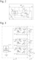
- FIG. 1 illustrates a rechargeable energy storage system 10 according to an embodiment of the present invention.
- the method carried out by this storage system 10 is defined in the third embodiment.
- a central controller 20 and a controller 18 co-operate to execute this method.
- the rechargeable energy storage devices 12 may be Lithium capacitors or batteries, for example high energy-density batteries, such as for example Lithium or Lithium Ion (Lilon) batteries.
- Lithium capacitors have a low energy density compared to batteries and are extremely vulnerable to both overvoltage or undervoltage voltage conditions thus requiring accurate balancing both by charging and by discharging.
- Other kinds of rechargeable energy storage devices can equally be used. Preferred applications are in the fields of energy smoothing and momentary load devices, which require very high instant powers compared to the average power ratings.
- each rechargeable energy storage device 12 has a limited operating voltage, e.g. between 2 and 4 V.
- a useful operating voltage of, for example, a few tens to a few hundreds of Volts or even more, useful e.g. as an energy source in vehicle applications
- a plurality, and sometimes a large number of rechargeable energy storage devices 12 need to be coupled in series. Slight differences between the energy storage devices 12 in a string or series-coupling can produce imbalances in the cell voltages, which may greatly reduce the string's charge capacity.
- Each energy storage device 12 in the string 11 is provided with a first terminal 16, which is its positive terminal, and a second terminal 17 which is its negative terminal.
- the energy storage devices 12 are coupled in the string 11 such that a positive terminal 16 of a first energy storage device 12 is coupled to a negative terminal 17 of a second energy storage device, and so on.
- the negative terminal 17 of the very first energy storage device 12 in the string, and the positive terminal 16 of the very last energy storage device 12 in the string are accessible from outside.
- the balancing unit 15 furthermore comprises an input terminal P for receiving an input signal.
- This input terminal is electrically connected, over a first switch SW1 and a second switch SW2, to the first and second data input ports S+ and S-, respectively.
- the input signal is received from the AC signal generator 14.
- the balancing unit 15 is adapted for actuating the first and second switches SW1, SW2 in function of the voltage level at input terminal P. This actuation of the switches SW1, SW2 is controlled by a controller 18.
- the controller 18 can work in co-operation with a main controller 20.
- the control function may be concentrated in one controller or may be distributed over two or more levels. Fig. 1 shows 2 levels of controller but more may be used.
- a balancing unit 15 performs at least the following functions:
- all balancing units 15 of the system 13 for balancing are coupled to the AC signal generator 14.
- This AC signal generator 14 can be a block wave generator, a sinusoidal signal source, a saw tooth generator, or any other type of AC signal generator. It is advantageous if the AC signal generator 14 is a high frequency signal generator, as this reduces component size. A sinusoidal signal generator is more efficient, has low peak currents hence low heat generation, and does not substantially present any switching losses. However, a block wave generator is easier to implement than a sinusoidal signal generator.
- the AC signal generator 14 can be powered from an external source (not illustrated), e.g. a charger, or from the series string 11 of energy storage devices 12. The AC signal generator 14 can be controlled by the main controller 20. It is advantageous to have a single AC signal generator 14 for the balancing system 13. This embodiment is different from any prior art solutions, for example, where an AC signal generator is required in each balancing unit.
- the balancing units 15 are coupled to the AC signal generator by means of a capacitor 19.
- the capacitive coupling provided by the capacitors 19 is used to block common mode voltages. This is required because the energy storage devices 12 are at different and varying potential levels.
- Each balancing circuit 15 in first instance measures a local instantaneous electrical parameter of the associated energy storage device 12, e.g. the local voltage across its first and second terminals 16, 17, i.e. the voltage across the associated energy storage device 12.
- this measuring can be performed via a method and device as disclosed in WO 2006/058394 .
- the measurement can be performed by means of an A/D converter, for example an A/D converter 21 which forms part of a local controller 18, local to the balancing unit 15.
- An embodiment of the present invention describing balancing system can be implemented by a digital device with processing capability including one or more microprocessors, processors, controllers, or central processing units (CPU) and/or a Graphics Processing Units (GPU), means of communication and can be adapted to carry out the respective functions or tests by being programmed with software, i.e. one or more computer programs.
- a digital device with processing capability including one or more microprocessors, processors, controllers, or central processing units (CPU) and/or a Graphics Processing Units (GPU), means of communication and can be adapted to carry out the respective functions or tests by being programmed with software, i.e. one or more computer programs.
- V t V min + k * t + S
- the balancing method for capacitors described above can be applied to batteries the SoC can be used for the calculation of Q n or Q' n which is used in the decision to balance as described above. Similar to capacitor balancing optimal system performance is achieved talking into account the cell's capacity.
- a battery management system should be able to communicate to a bulk load or charger when to end charging and/or discharging. This can be done by checking individual cell voltages against their upper or lower limits and interrupting charge or discharge when a voltage goes beyond a limit. However, when the current to/from a storage device is interrupted, the voltage will abruptly change. All voltages will return to values within their limits which may lead to switching on of the load/charger discovering that the limits are again immediately exceeded. This oscillating behaviour is not desired. To avoid this behaviour, in absence of cell voltage measurements, the system voltage can be used to compare to a limit value.
- the limit value can be calculated as follows :
- the function lookup_EMF allows to determine a cell voltage based on its SoC.
- the relationship is generally supplied as part of a battery cell's data sheet and sometimes referred to as "voltage vs SOC" curve.
- Q l represents the total charge that the battery system can store until the smallest cell is full. It can be expressed in As (Ampere seconds) so if the current is known, the remaining charging time can be calculated. If a battery model is used to estimate cell SoC and cell capacity, this model will usually allow to convert a measured voltage and a predicted charge to a predicted voltage taking into account internal resistance. This voltage is used as upper limit voltage.
- a layered architecture is provided:
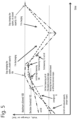
- Figure 5 shows a graph of voltage, charge or SoC for the vertical axis and time along the horizontal axis during balancing in accordance with embodiments of the present invention.
- the maximum limit allowed 100 means that charging of the system is terminated if a cell reaches this maximum.
- a steeper slope means that the voltage changes more quickly as charge is added or removed from the cells.
- the voltage of cells with smaller capacity changes faster than that of larger cells so slopes are steeper.
- the slopes are less.
- Cell 60 has a lower capacity than average and hence charges up faster. It therefore reaches the decision threshold 102 earlier than the average cell 70 and balancing starts in step 104 for cell 60.
- the average cell 70 will reach a lower charge or voltage or SoC when the cell 60 reaches the maximum at step 106. This means there is unused capacity in the system.
- the balancing of cell 60 continues in discharge so that the slope is steeper and becomes more shallow when balancing stops in step 112.
- the steeper slope initially means that the cell 60 reaches a lower voltage, charge or SoC than the average cell 70 when the system starts to charge again in step 116.
- the charging of the system is in step 116 and if the balancing has been done optimally whereby balancing by charging or discharging can be selected freely independent of whether the whole system is charging, discharging or is idle then there is no waste capacity at the maximum 118.
- balancing starts at step 108 and stops at step 110.
- An embodiment of the present invention describing balancing system can be implemented by a digital device with processing capability including one or more microprocessors, processors, controllers, or central processing units (CPU) and/or a Graphics Processing Units (GPU), means of communication such as described with reference to the first and second embodiment, any of which can be adapted to carry out the respective functions or tests by being programmed with software, i.e. one or more computer programs.
- a digital device with processing capability including one or more microprocessors, processors, controllers, or central processing units (CPU) and/or a Graphics Processing Units (GPU), means of communication such as described with reference to the first and second embodiment, any of which can be adapted to carry out the respective functions or tests by being programmed with software, i.e. one or more computer programs.
- Such a device may have memory (such as non-transitory computer readable medium, RAM and/or ROM), an operating system, optionally a display such as a fixed format display such as an OLED display, data entry devices such as a keyboard, a pointer device such as a "mouse", serial or parallel ports to communicate with other devices, network cards and connections to connect to a network.
- memory such as non-transitory computer readable medium, RAM and/or ROM
- an operating system optionally a display such as a fixed format display such as an OLED display, data entry devices such as a keyboard, a pointer device such as a "mouse”, serial or parallel ports to communicate with other devices, network cards and connections to connect to a network.
- a display such as a fixed format display such as an OLED display
- data entry devices such as a keyboard
- a pointer device such as a "mouse”
- serial or parallel ports to communicate with other devices, network cards and connections to connect to a network.
- the software can be embodied in a computer program product adapted to carry out the following functions for balancing individual electric energy storage devices in an electric energy storage system comprising individual energy storage devices connected in series, when the software is loaded onto the respective device or devices and executed on one or more processing engines such as microprocessors, ASIC's, FPGA's etc.: measuring an electrical parameter of individual energy storage devices related to device health, charge or state of charge.
- processing engines such as microprocessors, ASIC's, FPGA's etc.: measuring an electrical parameter of individual energy storage devices related to device health, charge or state of charge.
- the software is embodied in the computer program product and adapted to carry out the following functions when the software is loaded onto the respective device or devices and executed on one or more processing engines such as microprocessors, ASIC's, FPGA's etc.: deciding if one or more individual energy storage devices are to be balanced and in which direction , the decision being based on the measured parameter values.
- processing engines such as microprocessors, ASIC's, FPGA's etc.: deciding if one or more individual energy storage devices are to be balanced and in which direction , the decision being based on the measured parameter values.
- the software is embodied in the computer program product and adapted to carry out the following functions when the software is loaded onto the respective device or devices and executed on one or more processing engines such as microprocessors, ASIC's, FPGA's etc.: performing balancing of the one or more energy storage devices independently of whether the energy storage system as a whole is being charged or discharged or is idle.
- processing engines such as microprocessors, ASIC's, FPGA's etc.: performing balancing of the one or more energy storage devices independently of whether the energy storage system as a whole is being charged or discharged or is idle.
- the software is embodied in the computer program product and adapted to carry out the following functions when the software is loaded onto the respective device or devices and executed on one or more processing engines such as microprocessors, ASIC's, FPGA's etc.: balancing carried out according to any of the following:
- the software is embodied in the computer program product and adapted to carry out the following functions when the software is loaded onto the respective device or devices and executed on one or more processing engines such as microprocessors, ASIC's, FPGA's etc.: transferring, on the one hand, charge from an electric charging device or from an energy storage device assigned to another balancing unit for charging the energy storage device assigned to the first balancing unit, and, on the other hand, for transferring charge to the electric charging device or to an energy storage device assigned to another balancing unit for discharging the energy storage device assigned to the first balancing unit independently of whether the energy storage system as a whole is being charged or discharged or is idle.
- processing engines such as microprocessors, ASIC's, FPGA's etc.
- the software is embodied in the computer program product and adapted to carry out the following functions when the software is loaded onto the respective device or devices and executed on one or more processing engines such as microprocessors, ASIC's, FPGA's etc.: comparing a measured electrical parameter of an energy storage device with a corresponding reference parameter or threshold value, and/or the electrical parameter can be a derived value such as an amount of charge in the energy storage device or an amount of charge left in the energy storage device or a SoC of the energy storage device.
- processing engines such as microprocessors, ASIC's, FPGA's etc.
- the software is embodied in the computer program product and adapted to carry out the following functions when the software is loaded onto the respective device or devices and executed on one or more processing engines such as microprocessors, ASIC's, FPGA's etc.:
- the software is embodied in the computer program product and adapted to carry out the following functions when the software is loaded onto the respective device or devices and executed on one or more processing engines such as microprocessors, ASIC's, FPGA's etc.: protecting the rechargeable energy storage devices against overvoltage and/or undervoltage.
- the software is embodied in the computer program product and adapted to carry out the following functions when the software is loaded onto the respective device or devices and executed on one or more processing engines such as microprocessors, ASIC's, FPGA's etc.:
- the cell is selected with the lowest value of Q which is a step of finding which cells to balance and a means for performing the finding operation.
- determining C n is a step of determining the health of a cell as well as providing a means to determine the health.
- the cell will be discharged independently of whether the energy storage device is discharging into a load or is being charged or is idle.
- the software is embodied in the computer program product and adapted to carry out the following functions when the software is loaded onto the respective device or devices and executed on one or more processing engines such as microprocessors, ASIC's, FPGA's etc.:
- Q' is the amount of charge left in an energy cell
- V min is the lowest allowed voltage state of complete useful discharge
- the cell is selected with the lowest value of Q' which is a step of finding which cells to balance and a means for performing the finding operation.
- Equation (1) can be evaluated when V n is close to V max or equation (2) can be evaluated when V n is close to V min .
- V t V max ⁇ k ⁇ t ⁇ S
- V' t V min + k ⁇ t + S
- the software is embodied in the computer program product and adapted to carry out the following functions when the software is loaded onto the respective device or devices and executed on one or more processing engines such as microprocessors, ASIC's, FPGA's etc.:
- the software is embodied in the computer program product and adapted to carry out the following functions when the software is loaded onto the respective device or devices and executed on one or more processing engines such as microprocessors, ASIC's, FPGA's etc.:
- the software is embodied in the computer program product and adapted to carry out the following functions when the software is loaded onto the respective device or devices and executed on one or more processing engines such as microprocessors, ASIC's, FPGA's etc.: communicating to a bulk load or charger when to end charging and/or discharging by checking individual cell voltages against their upper or lower limits and interrupting charge or discharge when a voltage goes beyond a limit.
- processing engines such as microprocessors, ASIC's, FPGA's etc.: communicating to a bulk load or charger when to end charging and/or discharging by checking individual cell voltages against their upper or lower limits and interrupting charge or discharge when a voltage goes beyond a limit.
- the software is embodied in the computer program product and adapted to carry out the following functions when the software is loaded onto the respective device or devices and executed on one or more processing engines such as microprocessors, ASIC's, FPGA's etc.: when the current to/from a storage device is interrupted, the voltage will abruptly change whereby to avoid oscillating behaviour, in absence of cell voltage measurements, comparing the system voltage to a limit value, and/or
- the limit value can be calculated as follows :
- the computer program product can be stored on a non-transitory signal storage means such as an optical disk (CD-ROM or DVD-ROM, a magnetic disk, a magnetic tape, a solid state memory such as a flash memory.
- a non-transitory signal storage means such as an optical disk (CD-ROM or DVD-ROM, a magnetic disk, a magnetic tape, a solid state memory such as a flash memory.
Landscapes
- Engineering & Computer Science (AREA)
- Power Engineering (AREA)
- Physics & Mathematics (AREA)
- General Physics & Mathematics (AREA)
- Charge And Discharge Circuits For Batteries Or The Like (AREA)
- Secondary Cells (AREA)
- Protection Of Static Devices (AREA)
Applications Claiming Priority (3)
| Application Number | Priority Date | Filing Date | Title |
|---|---|---|---|
| EP15202756 | 2015-12-24 | ||
| EP16158197 | 2016-03-02 | ||
| PCT/EP2016/082665 WO2017109226A1 (en) | 2015-12-24 | 2016-12-23 | Method, system and device for balancing individual electric energy storage cells |
Publications (3)
| Publication Number | Publication Date |
|---|---|
| EP3394950A1 EP3394950A1 (en) | 2018-10-31 |
| EP3394950C0 EP3394950C0 (en) | 2025-07-09 |
| EP3394950B1 true EP3394950B1 (en) | 2025-07-09 |
Family
ID=57796324
Family Applications (1)
| Application Number | Title | Priority Date | Filing Date |
|---|---|---|---|
| EP16826065.1A Active EP3394950B1 (en) | 2015-12-24 | 2016-12-23 | Method, system and device for balancing individual electric energy storage cells |
Country Status (8)
| Country | Link |
|---|---|
| US (1) | US10833513B2 (enExample) |
| EP (1) | EP3394950B1 (enExample) |
| JP (1) | JP2019501616A (enExample) |
| CN (1) | CN108432083A (enExample) |
| CA (1) | CA3007612A1 (enExample) |
| ES (1) | ES3036519T3 (enExample) |
| PL (1) | PL3394950T3 (enExample) |
| WO (1) | WO2017109226A1 (enExample) |
Families Citing this family (29)
| Publication number | Priority date | Publication date | Assignee | Title |
|---|---|---|---|---|
| EP3398239A1 (en) * | 2015-12-29 | 2018-11-07 | Vito NV | Device and method for the reconfiguration of a rechargeable energy storage device into separate battery connection strings |
| US11201478B2 (en) * | 2016-09-13 | 2021-12-14 | Sanyo Electric Co., Ltd. | Management device and power supply system for improved cell voltage detection accuracy |
| US11124087B2 (en) * | 2016-12-01 | 2021-09-21 | Volvo Truck Corporation | System and a method for selecting energy storage cells for balancing of an electrical energy storage pack |
| EP3333008B1 (en) * | 2016-12-12 | 2022-06-15 | Honeywell International Inc. | Adaptive balancing for battery management |
| DE102017213020B4 (de) * | 2017-07-28 | 2024-10-02 | Bayerische Motoren Werke Aktiengesellschaft | Vorrichtung und verfahren zur symmetrierung eines energiespeichermoduls |
| US10444295B2 (en) * | 2017-12-20 | 2019-10-15 | National Chung Shan Institute Of Science And Technology | Battery balance management circuit |
| CN109038707B (zh) * | 2018-07-05 | 2020-05-19 | 华中科技大学 | 一种电池组分段混合均衡控制方法 |
| CN112514196A (zh) | 2018-07-31 | 2021-03-16 | 赛昂能源有限公司 | 多路复用的充放电电池管理系统 |
| EP3846310A4 (en) * | 2018-08-29 | 2021-07-07 | Nuvoton Technology Corporation Japan | MANAGEMENT SYSTEM AND CELL MONITORING CIRCUIT |
| US20210249981A1 (en) | 2018-09-05 | 2021-08-12 | Dpm Technologies Inc. | Systems and methods for intelligent control of rotating electric machines |
| DE102018124547A1 (de) * | 2018-10-04 | 2020-04-09 | Jungheinrich Aktiengesellschaft | Verfahren zum Laden einer Batterie |
| CN110096780B (zh) * | 2019-04-23 | 2020-08-28 | 西安交通大学 | 一种超级电容一阶rc网络等效电路及参数确定方法 |
| US11722026B2 (en) | 2019-04-23 | 2023-08-08 | Dpm Technologies Inc. | Fault tolerant rotating electric machine |
| EP3751299B1 (en) * | 2019-06-11 | 2023-08-09 | Volvo Car Corporation | Detecting latent faults within a cell of an energy storage system |
| US11211803B2 (en) * | 2019-10-01 | 2021-12-28 | GM Global Technology Operations LLC | Method and apparatus for battery cell charge balancing |
| US11424492B2 (en) | 2019-10-31 | 2022-08-23 | Sion Power Corporation | System and method for operating a rechargeable electrochemical cell or battery |
| SE543842C2 (en) * | 2019-12-12 | 2021-08-10 | Scania Cv Ab | A method of controlling the output voltage of a battery module comprising a plurality of switched battery cell units, and a battery module |
| TWI757673B (zh) * | 2019-12-25 | 2022-03-11 | 宏碁股份有限公司 | 平衡充電方法與充電裝置 |
| US20210336448A1 (en) * | 2020-04-01 | 2021-10-28 | ZapBatt, Inc. | Battery Management System with Control and Discharge Electronics |
| US20210344208A1 (en) * | 2020-04-21 | 2021-11-04 | ZapBatt, Inc. | EV Charging System for Micromobility Vehicles Having a Battery Management System with Control and Discharge Electronics |
| EP4208931A1 (en) * | 2020-09-01 | 2023-07-12 | Sion Power Corporation | Multiplexed battery management system |
| WO2022169980A1 (en) | 2021-02-05 | 2022-08-11 | Sion Power Corporation | Charge/discharge management in electrochemical cells, including partial cycle control |
| US11897362B2 (en) * | 2021-05-04 | 2024-02-13 | Exro Technologies Inc. | Systems and methods for individual control of a plurality of controllable units of battery cells |
| CN117337545A (zh) | 2021-05-13 | 2024-01-02 | Exro技术公司 | 驱动多相电机的线圈的方法及装置 |
| KR20240046176A (ko) | 2021-07-08 | 2024-04-08 | 엑스로 테크놀로지스 아이엔씨. | 전기 기계의 와인딩들을 이용한 동적으로 재구성가능한 전력 변환기 |
| CN115774196B (zh) * | 2022-11-23 | 2025-07-08 | 中国铁塔股份有限公司四川省分公司 | 一种锂电池组安全裕度的估算方法 |
| US20240283272A1 (en) * | 2023-02-16 | 2024-08-22 | Advanced Energy Industries, Inc. | Adaptive output start-up ramp |
| CN116566007B (zh) * | 2023-05-16 | 2024-04-12 | 深圳三晖能源科技有限公司 | 电池充放电自动调节方法、装置和智能户外电源系统 |
| US20260121423A1 (en) | 2024-10-28 | 2026-04-30 | Skeleton Technologies GmbH | Computer-implemented method for discharging energy storage cells |
Citations (2)
| Publication number | Priority date | Publication date | Assignee | Title |
|---|---|---|---|---|
| US20110234170A1 (en) * | 2011-03-30 | 2011-09-29 | O2Micro, Inc. | Circuits, systems and methods for balancing battery cells |
| US9018892B2 (en) * | 2011-03-23 | 2015-04-28 | Indian Institute Of Technology Bombay | Photo-voltaic array fed switched capacitor DC-DC converter based battery charging for Li-Ion batteries |
Family Cites Families (14)
| Publication number | Priority date | Publication date | Assignee | Title |
|---|---|---|---|---|
| JP3746886B2 (ja) * | 1997-09-29 | 2006-02-15 | 三菱自動車工業株式会社 | 蓄電装置 |
| EP1662268A1 (en) | 2004-11-30 | 2006-05-31 | "VLAAMSE INSTELLING VOOR TECHNOLOGISCH ONDERZOEK", afgekort "V.I.T.O." | System and method for measuring fuel cell voltage |
| LT2302757T (lt) | 2009-09-24 | 2020-07-10 | Vito Nv (Vlaamse Instelling Voor Technologisch Onderzoek Nv) | Elektros energijos, akumuliatorinių elementų įtampos išlyginimo būdas ir sistema |
| US8339100B2 (en) * | 2009-09-29 | 2012-12-25 | O2Micro Inc | Systems and methods for cell balancing |
| HUP1000311A2 (en) * | 2010-06-14 | 2012-08-28 | Ferenc Stangl | System and method for charge equalisation and/or charring of electrical energy storing units |
| US9568555B2 (en) * | 2010-12-06 | 2017-02-14 | Peter Fredrick Nortman | Electrochemical cell monitoring and balancing circuit with self-diagnostic feature |
| JP5472077B2 (ja) * | 2010-12-21 | 2014-04-16 | 三菱自動車工業株式会社 | 電池満充電容量推定装置 |
| US9252602B2 (en) * | 2011-05-23 | 2016-02-02 | Hitachi Automotive Systems, Ltd. | Electric storage cell control circuit |
| JP5861063B2 (ja) * | 2011-10-27 | 2016-02-16 | パナソニックIpマネジメント株式会社 | 蓄電装置及び電力供給システム |
| JP2013123274A (ja) * | 2011-12-09 | 2013-06-20 | Nissan Motor Co Ltd | 組電池の制御装置 |
| US9770997B2 (en) * | 2013-06-11 | 2017-09-26 | Ford Global Technologies, Llc | Detection of imbalance across multiple battery cells measured by the same voltage sensor |
| US9531038B2 (en) * | 2013-07-31 | 2016-12-27 | Dell Products, Lp | System and method of cell block voltage analytics to improve balancing effectiveness and identify self-discharge rate |
| JP6264162B2 (ja) * | 2014-04-04 | 2018-01-24 | 株式会社村田製作所 | 充電装置および充電制御方法、並びに、蓄電装置、電力貯蔵装置、電力システムおよび電動車両 |
| BR112016027664B1 (pt) * | 2014-05-28 | 2022-02-22 | Volvo Truck Corporation | Método para determinação da confiabilidade de valores de parâmetro de estado de saúde |
-
2016
- 2016-12-23 ES ES16826065T patent/ES3036519T3/es active Active
- 2016-12-23 JP JP2018532683A patent/JP2019501616A/ja active Pending
- 2016-12-23 EP EP16826065.1A patent/EP3394950B1/en active Active
- 2016-12-23 PL PL16826065.1T patent/PL3394950T3/pl unknown
- 2016-12-23 CA CA3007612A patent/CA3007612A1/en not_active Abandoned
- 2016-12-23 WO PCT/EP2016/082665 patent/WO2017109226A1/en not_active Ceased
- 2016-12-23 CN CN201680076157.XA patent/CN108432083A/zh active Pending
- 2016-12-23 US US16/062,181 patent/US10833513B2/en not_active Expired - Fee Related
Patent Citations (2)
| Publication number | Priority date | Publication date | Assignee | Title |
|---|---|---|---|---|
| US9018892B2 (en) * | 2011-03-23 | 2015-04-28 | Indian Institute Of Technology Bombay | Photo-voltaic array fed switched capacitor DC-DC converter based battery charging for Li-Ion batteries |
| US20110234170A1 (en) * | 2011-03-30 | 2011-09-29 | O2Micro, Inc. | Circuits, systems and methods for balancing battery cells |
Also Published As
| Publication number | Publication date |
|---|---|
| EP3394950C0 (en) | 2025-07-09 |
| JP2019501616A (ja) | 2019-01-17 |
| EP3394950A1 (en) | 2018-10-31 |
| US20180366959A1 (en) | 2018-12-20 |
| CA3007612A1 (en) | 2017-06-29 |
| CN108432083A (zh) | 2018-08-21 |
| ES3036519T3 (en) | 2025-09-19 |
| WO2017109226A1 (en) | 2017-06-29 |
| PL3394950T3 (pl) | 2025-09-01 |
| US10833513B2 (en) | 2020-11-10 |
Similar Documents
| Publication | Publication Date | Title |
|---|---|---|
| EP3394950B1 (en) | Method, system and device for balancing individual electric energy storage cells | |
| EP3664247B1 (en) | Charging time computation method and charge control device | |
| US8134342B2 (en) | Method for pulsed charging of a battery in an autonomous system comprising a supercapacitance | |
| JP3217529U (ja) | 蓄電池および蓄電池管理システム | |
| CN103548233B (zh) | 蓄电器控制电路 | |
| JP7276893B2 (ja) | 電源システム、及び管理装置 | |
| CN105814768B (zh) | 蓄电系统 | |
| US20120176095A1 (en) | Electric power management system | |
| EP3663780A1 (en) | Deterioration state computation method and deterioration state computation device | |
| US9780592B2 (en) | Battery pack for selectively setting a high capacity mode having a high charge capacity until a full charge of a secondary battery | |
| EP2762907A1 (en) | Apparatus and method for estimating state of charge of battery | |
| US11269392B2 (en) | System and method for maintaining power source | |
| US9184600B2 (en) | Method for balancing the voltages of electrochemical cells connected in several parallel branches | |
| EP4304042A1 (en) | Energy storage system, control method for energy storage system, and photovoltaic power generation system | |
| CN106463985B (zh) | 平衡校正控制装置、平衡校正系统及蓄电系统 | |
| JP2013042598A (ja) | 充放電制御装置 | |
| Yuang-Shung et al. | Fuzzy-controlled individual-cell equaliser using discontinuous inductor current-mode Cuk convertor for lithium–ion chemistries | |
| KR101967863B1 (ko) | 고전압 셀 밸런싱의 밸런싱 필요 시간 추정 장치 및 방법 | |
| JP2019024285A (ja) | バランス装置および電池ユニット | |
| EP4260429A1 (en) | Method and system for balancing charge of battery cells | |
| JP2011193653A (ja) | アクティブ制御蓄電池 | |
| US20250047110A1 (en) | Methods and apparatus for battery cell management | |
| Muflih et al. | Parallel Balancing Battery using Adaptive Power Sharing and ANN SOC Estimator | |
| Eseosa et al. | A comprehensive study on lithium-ion battery management system | |
| Liedke et al. | Selection of ahi+ sc hybrid storage based on mathematical models and load variation characteristics |
Legal Events
| Date | Code | Title | Description |
|---|---|---|---|
| STAA | Information on the status of an ep patent application or granted ep patent |
Free format text: STATUS: UNKNOWN |
|
| STAA | Information on the status of an ep patent application or granted ep patent |
Free format text: STATUS: THE INTERNATIONAL PUBLICATION HAS BEEN MADE |
|
| PUAI | Public reference made under article 153(3) epc to a published international application that has entered the european phase |
Free format text: ORIGINAL CODE: 0009012 |
|
| STAA | Information on the status of an ep patent application or granted ep patent |
Free format text: STATUS: REQUEST FOR EXAMINATION WAS MADE |
|
| 17P | Request for examination filed |
Effective date: 20180709 |
|
| AK | Designated contracting states |
Kind code of ref document: A1 Designated state(s): AL AT BE BG CH CY CZ DE DK EE ES FI FR GB GR HR HU IE IS IT LI LT LU LV MC MK MT NL NO PL PT RO RS SE SI SK SM TR |
|
| AX | Request for extension of the european patent |
Extension state: BA ME |
|
| STAA | Information on the status of an ep patent application or granted ep patent |
Free format text: STATUS: EXAMINATION IS IN PROGRESS |
|
| DAV | Request for validation of the european patent (deleted) | ||
| DAX | Request for extension of the european patent (deleted) | ||
| 17Q | First examination report despatched |
Effective date: 20190401 |
|
| P01 | Opt-out of the competence of the unified patent court (upc) registered |
Effective date: 20230528 |
|
| GRAP | Despatch of communication of intention to grant a patent |
Free format text: ORIGINAL CODE: EPIDOSNIGR1 |
|
| STAA | Information on the status of an ep patent application or granted ep patent |
Free format text: STATUS: GRANT OF PATENT IS INTENDED |
|
| INTG | Intention to grant announced |
Effective date: 20250130 |
|
| GRAS | Grant fee paid |
Free format text: ORIGINAL CODE: EPIDOSNIGR3 |
|
| GRAA | (expected) grant |
Free format text: ORIGINAL CODE: 0009210 |
|
| STAA | Information on the status of an ep patent application or granted ep patent |
Free format text: STATUS: THE PATENT HAS BEEN GRANTED |
|
| AK | Designated contracting states |
Kind code of ref document: B1 Designated state(s): AL AT BE BG CH CY CZ DE DK EE ES FI FR GB GR HR HU IE IS IT LI LT LU LV MC MK MT NL NO PL PT RO RS SE SI SK SM TR |
|
| REG | Reference to a national code |
Ref country code: GB Ref legal event code: FG4D |
|
| REG | Reference to a national code |
Ref country code: CH Ref legal event code: EP |
|
| REG | Reference to a national code |
Ref country code: IE Ref legal event code: FG4D |
|
| REG | Reference to a national code |
Ref country code: DE Ref legal event code: R096 Ref document number: 602016092860 Country of ref document: DE |
|
| U01 | Request for unitary effect filed |
Effective date: 20250723 |
|
| U07 | Unitary effect registered |
Designated state(s): AT BE BG DE DK EE FI FR IT LT LU LV MT NL PT RO SE SI Effective date: 20250729 |
|
| REG | Reference to a national code |
Ref country code: ES Ref legal event code: FG2A Ref document number: 3036519 Country of ref document: ES Kind code of ref document: T3 Effective date: 20250919 |
|
| U20 | Renewal fee for the european patent with unitary effect paid |
Year of fee payment: 10 Effective date: 20251119 |
|
| REG | Reference to a national code |
Ref country code: CH Ref legal event code: U11 Free format text: ST27 STATUS EVENT CODE: U-0-0-U10-U11 (AS PROVIDED BY THE NATIONAL OFFICE) Effective date: 20260101 |
|
| PG25 | Lapsed in a contracting state [announced via postgrant information from national office to epo] |
Ref country code: IS Free format text: LAPSE BECAUSE OF FAILURE TO SUBMIT A TRANSLATION OF THE DESCRIPTION OR TO PAY THE FEE WITHIN THE PRESCRIBED TIME-LIMIT Effective date: 20251109 |
|
| PGFP | Annual fee paid to national office [announced via postgrant information from national office to epo] |
Ref country code: GB Payment date: 20251119 Year of fee payment: 10 |
|
| PG25 | Lapsed in a contracting state [announced via postgrant information from national office to epo] |
Ref country code: NO Free format text: LAPSE BECAUSE OF FAILURE TO SUBMIT A TRANSLATION OF THE DESCRIPTION OR TO PAY THE FEE WITHIN THE PRESCRIBED TIME-LIMIT Effective date: 20251009 |
|
| PG25 | Lapsed in a contracting state [announced via postgrant information from national office to epo] |
Ref country code: HR Free format text: LAPSE BECAUSE OF FAILURE TO SUBMIT A TRANSLATION OF THE DESCRIPTION OR TO PAY THE FEE WITHIN THE PRESCRIBED TIME-LIMIT Effective date: 20250709 |
|
| PG25 | Lapsed in a contracting state [announced via postgrant information from national office to epo] |
Ref country code: GR Free format text: LAPSE BECAUSE OF FAILURE TO SUBMIT A TRANSLATION OF THE DESCRIPTION OR TO PAY THE FEE WITHIN THE PRESCRIBED TIME-LIMIT Effective date: 20251010 |
|
| PGFP | Annual fee paid to national office [announced via postgrant information from national office to epo] |
Ref country code: PL Payment date: 20251120 Year of fee payment: 10 |
|
| PG25 | Lapsed in a contracting state [announced via postgrant information from national office to epo] |
Ref country code: RS Free format text: LAPSE BECAUSE OF FAILURE TO SUBMIT A TRANSLATION OF THE DESCRIPTION OR TO PAY THE FEE WITHIN THE PRESCRIBED TIME-LIMIT Effective date: 20251009 |
|
| PG25 | Lapsed in a contracting state [announced via postgrant information from national office to epo] |
Ref country code: SM Free format text: LAPSE BECAUSE OF FAILURE TO SUBMIT A TRANSLATION OF THE DESCRIPTION OR TO PAY THE FEE WITHIN THE PRESCRIBED TIME-LIMIT Effective date: 20250709 |
|
| PGFP | Annual fee paid to national office [announced via postgrant information from national office to epo] |
Ref country code: ES Payment date: 20260102 Year of fee payment: 10 |
|
| PG25 | Lapsed in a contracting state [announced via postgrant information from national office to epo] |
Ref country code: CZ Free format text: LAPSE BECAUSE OF FAILURE TO SUBMIT A TRANSLATION OF THE DESCRIPTION OR TO PAY THE FEE WITHIN THE PRESCRIBED TIME-LIMIT Effective date: 20250709 |
|
| PGFP | Annual fee paid to national office [announced via postgrant information from national office to epo] |
Ref country code: CH Payment date: 20260101 Year of fee payment: 10 |
|
| PG25 | Lapsed in a contracting state [announced via postgrant information from national office to epo] |
Ref country code: SK Free format text: LAPSE BECAUSE OF FAILURE TO SUBMIT A TRANSLATION OF THE DESCRIPTION OR TO PAY THE FEE WITHIN THE PRESCRIBED TIME-LIMIT Effective date: 20250709 |